EP4327958A1 - Bending system, and split mold arrangement method - Google Patents
Bending system, and split mold arrangement method Download PDFInfo
- Publication number
- EP4327958A1 EP4327958A1 EP22791714.3A EP22791714A EP4327958A1 EP 4327958 A1 EP4327958 A1 EP 4327958A1 EP 22791714 A EP22791714 A EP 22791714A EP 4327958 A1 EP4327958 A1 EP 4327958A1
- Authority
- EP
- European Patent Office
- Prior art keywords
- tool
- retention member
- lower tool
- tools
- moving
- Prior art date
- Legal status (The legal status is an assumption and is not a legal conclusion. Google has not performed a legal analysis and makes no representation as to the accuracy of the status listed.)
- Pending
Links
Images




Classifications
-
- B—PERFORMING OPERATIONS; TRANSPORTING
- B30—PRESSES
- B30B—PRESSES IN GENERAL
- B30B15/00—Details of, or accessories for, presses; Auxiliary measures in connection with pressing
- B30B15/02—Dies; Inserts therefor; Mounting thereof; Moulds
- B30B15/026—Mounting of dies, platens or press rams
-
- B—PERFORMING OPERATIONS; TRANSPORTING
- B21—MECHANICAL METAL-WORKING WITHOUT ESSENTIALLY REMOVING MATERIAL; PUNCHING METAL
- B21D—WORKING OR PROCESSING OF SHEET METAL OR METAL TUBES, RODS OR PROFILES WITHOUT ESSENTIALLY REMOVING MATERIAL; PUNCHING METAL
- B21D5/00—Bending sheet metal along straight lines, e.g. to form simple curves
- B21D5/004—Bending sheet metal along straight lines, e.g. to form simple curves with program control
-
- B—PERFORMING OPERATIONS; TRANSPORTING
- B21—MECHANICAL METAL-WORKING WITHOUT ESSENTIALLY REMOVING MATERIAL; PUNCHING METAL
- B21D—WORKING OR PROCESSING OF SHEET METAL OR METAL TUBES, RODS OR PROFILES WITHOUT ESSENTIALLY REMOVING MATERIAL; PUNCHING METAL
- B21D37/00—Tools as parts of machines covered by this subclass
- B21D37/14—Particular arrangements for handling and holding in place complete dies
-
- B—PERFORMING OPERATIONS; TRANSPORTING
- B21—MECHANICAL METAL-WORKING WITHOUT ESSENTIALLY REMOVING MATERIAL; PUNCHING METAL
- B21D—WORKING OR PROCESSING OF SHEET METAL OR METAL TUBES, RODS OR PROFILES WITHOUT ESSENTIALLY REMOVING MATERIAL; PUNCHING METAL
- B21D5/00—Bending sheet metal along straight lines, e.g. to form simple curves
- B21D5/002—Positioning devices
-
- B—PERFORMING OPERATIONS; TRANSPORTING
- B21—MECHANICAL METAL-WORKING WITHOUT ESSENTIALLY REMOVING MATERIAL; PUNCHING METAL
- B21D—WORKING OR PROCESSING OF SHEET METAL OR METAL TUBES, RODS OR PROFILES WITHOUT ESSENTIALLY REMOVING MATERIAL; PUNCHING METAL
- B21D5/00—Bending sheet metal along straight lines, e.g. to form simple curves
- B21D5/02—Bending sheet metal along straight lines, e.g. to form simple curves on press brakes without making use of clamping means
- B21D5/0209—Tools therefor
-
- B—PERFORMING OPERATIONS; TRANSPORTING
- B21—MECHANICAL METAL-WORKING WITHOUT ESSENTIALLY REMOVING MATERIAL; PUNCHING METAL
- B21D—WORKING OR PROCESSING OF SHEET METAL OR METAL TUBES, RODS OR PROFILES WITHOUT ESSENTIALLY REMOVING MATERIAL; PUNCHING METAL
- B21D5/00—Bending sheet metal along straight lines, e.g. to form simple curves
- B21D5/02—Bending sheet metal along straight lines, e.g. to form simple curves on press brakes without making use of clamping means
- B21D5/0209—Tools therefor
- B21D5/0236—Tool clamping
-
- B—PERFORMING OPERATIONS; TRANSPORTING
- B21—MECHANICAL METAL-WORKING WITHOUT ESSENTIALLY REMOVING MATERIAL; PUNCHING METAL
- B21D—WORKING OR PROCESSING OF SHEET METAL OR METAL TUBES, RODS OR PROFILES WITHOUT ESSENTIALLY REMOVING MATERIAL; PUNCHING METAL
- B21D5/00—Bending sheet metal along straight lines, e.g. to form simple curves
- B21D5/02—Bending sheet metal along straight lines, e.g. to form simple curves on press brakes without making use of clamping means
- B21D5/0209—Tools therefor
- B21D5/0254—Tool exchanging
-
- B—PERFORMING OPERATIONS; TRANSPORTING
- B30—PRESSES
- B30B—PRESSES IN GENERAL
- B30B15/00—Details of, or accessories for, presses; Auxiliary measures in connection with pressing
- B30B15/02—Dies; Inserts therefor; Mounting thereof; Moulds
- B30B15/028—Loading or unloading of dies, platens or press rams
Definitions
- the present disclosure relates to a bending system and a divided tool arrangement method.
- a bending system includes a press brake that bends a workpiece, and the press brake includes a table and a tool holder that is provided to the table and holds a tool. Further, the bending system includes a tool rack that is disposed to a side of the press brake and stores a plurality of the tools. The tool rack includes a plurality of stockers that hold the tools, and a selected arbitrary stocker is configured to be able to be positioned at a change position at which tool change is performed. Furthermore, the bending system includes left and right tool change units that transport the tool between the tool holder and the stocker positioned at the change position so as to arrange the tool at a desired position of the tool holder. Each of the tool change units includes a tool retention member capable of being inserted into and removed from an insertion hole provided to the tool (see Patent Literature 1).
- Patent Literature 1 Japanese Patent No. 5947861
- a gathering operation is performed to gather the plurality of the tools so that there are no gaps between the tools.
- This gathering operation is performed by inserting the tool retention member into the insertion hole of the tool.
- an alarm is generated. Then, there is an inconvenience that the gathering operation is interrupted.
- a bending system includes a press brake in which a plurality of tools are arranged along a left-right direction in a tool holder provided to a table, a first moving body and a second moving body each including a tool retention member capable of being inserted into and removed from an insertion hole provided to the tool by moving forward and moving backward along a front-back direction, and provided on a rear surface side or a front surface side of the table so as to be movable in the left-right direction, and a control device configured to control each of the first and second moving bodies so as to perform a gathering operation of gathering the plurality of tools so that there are no gaps between the tools.
- the gathering operation includes a restraint operation of moving forward a first tool retention member of the first moving body so as to restrain a reference tool positioned at one end of the plurality of tools with the first tool retention member, an inserting operation of moving forward a second tool retention member of the second moving body so as to insert the second tool retention member into the insertion hole of a target tool selected from among remaining tools, which exclude the reference tool, of the plurality of tools, and an execution operation of moving the first and second moving bodies along the left-right direction so as to come close to each other so that the tools from the reference tool to the target tool are gathered.
- the control device When the failure of the inserting operation is determined, the control device performs a retry operation of moving forward the second tool retention member again to insert the second tool retention member into the insertion hole of the target tool after moving backward the first tool retention member to release the restraint operation.
- the retry operation when the failure of the inserting operation is determined, the retry operation is performed.
- This retry operation is performed in a state in which the reference tool is released from restraint by moving backward the first tool retention member.
- a margin is generated for the reference tool to slightly move, and the reference tool to the target tool can move slightly as a whole. Thanks to this, in the retry operation, the second tool retention member can be easily inserted into the target tool.
- the gathering operation can be continued without generating the alarm.
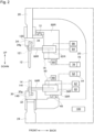
- Figure 1 is a front view schematically showing a configuration of a bending system according to a first embodiment.
- Figure 2 is a side view schematically showing the configuration of the bending system shown in Figure 1 .
- a bending system 10 according to the first embodiment will be described with reference to Figures 1 and 2 .
- directions a left-right direction, a front-back direction, and an up-down direction are defined, but these directions are used only for convenience of description.
- the left-right direction and the front-back direction correspond to two directions that are orthogonal to each other in a horizontal direction
- the up-down direction corresponds to a vertical direction.
- the bending system 10 includes a press brake 16 in which a plurality of lower tools 14 are arranged along the left-right direction in a lower tool holder 30 provided to a lower table 24, left and right lower tool change units 50L and 50R each including a lower tool retention member capable of being inserted into and removed from an insertion hole 141 provided to the lower tool 14 by moving forward and moving backward along the front-back direction, and provided on a rear surface side or a front surface side of the lower table 24 so as to be movable in the left-right direction, and a control device 100 configured to control each of the left and right lower tool change units 50L and 50R so as to perform a gathering operation of gathering the plurality of lower tools 14 so that there are no gaps between the lower tools 14.
- the gathering operation includes a restraint operation of moving forward a lower tool retention member 64L of the left lower tool change unit 50L so as to restrain a reference lower tool 14 positioned at one end of the plurality of lower tools 14 with the left lower tool retention member 64L, an inserting operation of moving forward a lower tool retention member 64R of the right lower tool change unit 50R so as to insert the lower tool retention member 64R into the insertion hole 141 of the target lower tool 14 selected from among remaining lower tools 14, which exclude a reference lower tool 14, of the plurality of lower tools 14, and an execution operation of moving the left and right lower tool change units 50L and 50R along the left-right direction so as to come close with each other so that the lower tools 14 from the reference lower tool 14 to the target lower tool 14 are gathered.
- the control device 100 When a failure of the inserting operation is determined, the control device 100 performs a retry operation of moving forward the right lower tool retention member 64R again to insert the right lower tool retention member 64R into the insertion hole 141 of the target lower tool 14 after moving backward the left lower tool retention member 64L to release the restraint operation of the reference lower tool 14.
- the above description relates to the gathering operation by way of the left and right lower tool change units 50L and 50R provided in correspondence with the lower tools 14, but the same applies to a gathering operation by way of left and right upper tool change units 74L and 74R provided in correspondence with upper tools 12.
- the bending system 10 is a system for bending a plate-shaped workpiece W such as a sheet metal, for example.
- the bending system 10 includes the press brake 16, the left and right lower tool change units 50L and 50R, the left and right upper tool change units 74L and 74R, and the control device 100.
- the press brake 16 bends the workpiece W through a cooperation of the upper tool 12, which is an upper tool such as a punch, and the lower tool 14, which is a lower tool such as a die.
- the press brake 16 includes a main frame 18.
- the main frame 18 includes left and right side plates 20 facing each other with a space therebetween in the left-right direction.
- the lower table 24 extending in the left-right direction is provided below the main frame 18, and an upper table 26 extending in the left-right direction is provided above the main frame 18.
- the upper table 26 is configured to be movable along the up-down direction.
- a hydraulic cylinder 28 is provided as an actuator for an up-down movement that moves the upper table 26 in the up-down direction with respect to the main frame 18.
- the lower table 24 may be configured to be movable in the up-down direction.
- a servo motor may be used as the actuator for the up-down movement.
- a lower tool holder 30 that holds the lower tool 14 in an installable and removable manner is provided on an upper side of the lower table 24.
- the lower tool holder 30 is configured, for example, to extend continuously along the left-right direction, but may be configured to be intermittently provided along the left-right direction at appropriate intervals.
- a holder groove 30g for a shank portion (base portion) 140 of the lower tool 14 to be inserted is formed along the left-right direction.
- the lower tool holder 30 includes a hydraulic clamp 32 that secures the lower tool 14 to the lower table 24.
- An upper tool holder 34 that holds the upper tool 12 in an installable and removable manner is provided on a lower side of the upper table 26.
- the upper tool holder 34 is configured, for example, to extend continuously along the left-right direction, but may be configured to be intermittently provided along the left-right direction at appropriate intervals.
- a holder groove 34g for a shank portion (base portion) 120 of the upper tool 12 to be inserted is formed along the left-right direction.
- the upper tool holder 34 includes a hydraulic clamp 36 that secures the upper tool 12 to the upper table 26.
- the insertion hole 141 that penetrates along the front-back direction is provided in a center portion of the lower tool 14 in the left-right direction (width direction).
- the position of the insertion hole 141 in the lower tool 14 attached to the lower tool holder 30 can be specified as a position corresponding to half the value of a tool width with reference to a position of one of left and right side surfaces of the lower tool 14.
- an insertion hole 121 that penetrates along the front-back direction is provided to the upper tool 12.
- the bending system 10 includes a tool rack 42 that stores a plurality of the lower tools 14 and a plurality of the upper tools 12 on a lateral side of the press brake in the left-right direction, in the present embodiment, on the right side.
- the tool rack 42 includes a plurality of lower stockers each holding one or more lower tools 14, and the plurality of lower stockers are arranged side by side in the front-back direction.
- the plurality of lower stockers are configured to be movable in the up-down direction and the front-back direction by a stocker moving mechanism.
- the stocker moving mechanism can select an arbitrary lower stocker from among the plurality of lower stockers and move the selected lower stocker in the up-down direction and the front-back direction so as to position it at a change position for the lower tool.
- the change position for the lower tool is set at a position adjacent to the lower tool holder 30 in the left-right direction.
- the tool rack 42 includes a plurality of upper stockers each holding one or more upper tools 12.
- the configuration of each of the upper stocker is similar to that of the lower stocker.
- the left and right lower tool change units 50L and 50R perform transport of the lower tool 14 between the lower tool holder 30 and the lower stocker positioned at the change position for the lower tool, arrangement of the lower tool 14 in the lower tool holder 30, and the like.
- the left and right lower tool change units 50L and 50R correspond to first and second moving bodies provided in correspondence with the lower tool 14.
- the left and right lower tool change units 50L and 50R are provided on a rear surface side of the lower table 24.
- a lower guide 48 extending in the left-right direction is provided on a rear surface side of the lower tool holder 30.
- Each of the lower tool change units 50L and 50R is configured to be movable in the left-right direction via the lower guide 48.
- the left and right lower tool change units 50L and 50R are configured independently of each other and can operate independently of each other. Since the configurations of the left and right lower tool change units 50L and 50R correspond to each other, the right lower tool change unit 50R will be taken as an example below to describe the configuration thereof.
- the right lower tool change unit 50R is moved in the left-right direction by a driving of a servo motor 52 as an actuator for a lateral movement.
- the servo motor 52 includes an encoder 54 as a position detector that detects a position in the left-right direction of the lower tool change unit 50R.
- the right lower tool change unit 50R includes a lower unit main body 56R provided to the lower guide 48 so as to be movable in the left-right direction, and a lower support member 58R provided to the lower unit main body 56R so as to be movable in the front-back direction and the up-down direction.
- the lower support member 58R is moved in the front-back direction with respect to the lower unit main body 56R by a driving of a first air cylinder 60 as an actuator for a front-back movement.
- the lower support member 58R is moved in the up-down direction with respect to the lower unit main body 56R by a driving of a second air cylinder 62 that is an actuator for an up-down movement.
- the right lower tool change unit 50R includes the lower tool retention member 64R provided to the lower support member 58R so as to be movable in the front-back direction.
- the lower tool retention member 64R is moved in the front-back direction with respect to the lower support member 58R by a driving of a third air cylinder 66 as an actuator for the front-back movement.
- the lower tool retention member 64R is configured to be insertable into the insertion hole 141 of the lower tool 14.
- the left and right lower tool change units 50L and 50R transport and arrange the lower tool 14 in the lower tool holder 30.
- the lower tool change units 50L and 50R respectively move forward the lower tool retention members 64R and 64L to insert the lower tool retention members 64R and 64L into the insertion holes 141 of the lower tools 14, which makes it possible to hold the lower tools 14.
- the lower tool change units 50L and 50R move in the left-right direction, which makes it possible to transport the lower tools 14 in the left-right direction. Then, by positioning the lower tool change units 50L and 50R at predetermined positions, the lower tools 14 can be arranged at desired positions of the lower tool holder 30.
- the left and right lower tool change units 50L and 50R can transport and arrange the lower tools 14 independently from each other. Further, the left and right lower tool change units 50L and 50R respectively hold the lower tools 14 positioned at both of the left and right ends of the plurality of lower tools 14, which makes it possible to collectively transport and arrange the plurality of lower tools 14.
- the lower tool 14 When the lower tool 14 is transported and arranged, there may be a sufficient gap on the left side or the right side of the target lower tool 14. In this case, the lower tool 14 may be transported by bringing the lower tool retention members 64R and/or 64L into contact with one of the left and right side surfaces of the lower tool 14 without inserting the lower tool retention members 64R and 64L into the insertion holes 141, and then pushing a side surface thereof in the left-right direction.
- the left and right upper tool change units 74L and 74R perform transport of the upper tool 12 between the upper tool holder 34 and the upper stocker positioned at a change position for the upper tool, arrangement of the upper tool 12 in the upper tool holder 34, and the like.
- the left and right upper tool change units 74L and 74R correspond to the first and second moving bodies provided in correspondence with the upper tool 12.
- the configurations of the left and right upper tool change units 74L and 74R correspond to the configurations of the left and right lower tool change units 50L and 50R described above.
- an upper guide 72, a servo motor 76, an encoder 78, an upper unit main body 80R (80L), an upper support member 82R (82L), a first air cylinder 84, a second air cylinder 86, an upper tool retention member 88R (88L), and a third air cylinder 90 in the upper tool change unit 74R (74L) correspond to the lower guide 48, the servo motor 52, the encoder 54, the lower unit main body 56R (56L), the lower support member 58R (58L), the first air cylinder 60, the second air cylinder 62, the lower tool retention member 64R (64L), and the third air cylinder 66 in the lower tool change unit 50R (50L), respectively.
- the control device 100 is a device that controls an operation of the bending system 10.
- the control device 100 is, for example, a computer such as an NC device.
- the computer is mainly composed of a hardware processor such as a CPU (central processing unit), a memory, and various types of interfaces.
- the memory and the various types of interfaces are connected to the hardware processor via buses.
- Predetermined computer programs are installed on the computer.
- the hardware processor executes the computer programs so that the computer executes a plurality of functions provided to the control device 100.
- the control device 100 controls an operation of the press brake 16 based on a processing program. Further, the control device 100 controls operations of the left and right lower tool change units 50L and 50R and the left and right upper tool change units 74L and 74R, respectively, based on a tool change program and setup data. Under this control, the transport of the upper tool 12 and the lower tool 14, the respective arrangement of the upper tool 12 and the lower tool 14 in the upper tool holder 34 and the lower tool holder 30, and the like are performed.
- the memory of the control device 100 stores the processing program, the tool change program, and the setup data.
- the setup data is a data representing one or more tool stages simultaneously arranged in the tool holders (the upper tool holder 34 and the lower tool holder 30) of the press brake 16 among the plurality of tools (the upper tool 12 and the lower tool 14) of the bending system 10.
- the setup data includes information such as a setup number, a tool layout, and a component to be processed.
- the tool layout includes a tool number of the tool that makes up each stage, a length of the tool in a width direction, a mounting position of the tool in the tool holder, and the like.
- the tool stage arranged in the tool holder is composed of one tool or a group of tools in which the plurality of tools are combined in the left-right direction.
- one tool stage is composed of the tool group in which the plurality of tools are combined, these tools are continuously arranged in the left-right direction so that there are no gaps between the tools.
- the control device 100 arranges the plurality of lower tools 14 at predetermined positions of the lower tool holder 30 by position control of the left and right lower tool change units 50L and 50R. Specifically, the control device 100 controls the servo motors 52 that drive the left and right lower tool change units 50L and 50R, respectively, so as to perform the position controls of the left and right lower tool change units 50L and 50R in the left-right direction. In the position controls, the control device 100 can recognize the position of each of the left and right lower tool change units 50L and 50R in the left-right direction based on a detection signal supplied from the encoder 54 that detects the number of rotations of the servo motor 52.
- the control device 100 can move the left and right lower tool change units 50L and 50R in the left-right direction and position them at the predetermined positions in the left-right direction.
- the plurality of lower tools 14 can be arranged at the desired positions of the lower tool holder 30 by the movements in the left-right direction of the left and right lower tool change units 50L and 50R and the positioning operation thereof.
- the control device 100 controls the left and right lower tool change units 50L and 50R to perform the gathering operation of gathering the plurality of lower tools 14 so as to eliminate the gap generated between the lower tools. This gathering operation is performed by operating the left and right lower tool change units 50L and 50R under the position controls by the control device 100.
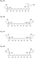
- FIGS 3A to 3D and Figures 4A to 4D are diagrams showing a procedure of the gathering operation according to the first embodiment.
- the gathering operation according to the first embodiment will be described below with reference to Figures 3A to 3D and Figures 4A to 4D .
- seven lower tools 14a to 14h are shown as examples of the plurality of lower tools 14.
- the seven lower tools 14a to 14h are arranged from left to right in the order of the lower tool 14a, the lower tool 14b, the lower tool 14c, the lower tool 14d, the lower tool 14e, the lower tool 14f, the lower tool 14g, and the lower tool 14h.
- the tool rack 42 is arranged on the right side of the press brake 16.
- the lower tool 14 transported from the tool rack 42 to the lower tool holder 30 mainly moves from the right side to the left side. Therefore, among the seven lower tools 14a to 14h, the lower tool 14a positioned at the leftmost end is used as a reference lower tool 14a that serves as a reference for the gathering operation.
- the reference lower tool is not limited to the lower tool 14a.
- the control device 100 moves the left lower tool change unit 50L in the left-right direction to align the left lower tool change unit 50L with the reference lower tool 14a (an alignment operation).
- the alignment operation is performed so that the position of the left lower tool retention member 64L and the position of the insertion hole 141 of the reference lower tool 14a are matched (the same applies to the following alignment operation).
- the control device 100 selects, as a first target lower tool, an arbitrary lower tool from among the remaining lower tools 14b to 14h that exclude the reference lower tool 14a.
- the lower tool 14e positioned in the middle of the remaining lower tools 14b to 14h is used as the first target lower tool 14e.
- the control device 100 moves the right lower tool change unit 50R in the left-right direction to align the right lower tool change unit 50R with the target lower tool 14e (the alignment operation).
- the control device 100 moves forward the left lower tool retention member 64L to insert the left lower tool retention member 64L into the insertion hole 141 of the reference lower tool 14a.
- the reference lower tool 14a is restricted by the left lower tool retention member 64L (restraint operation).
- the control device 100 moves forward the right lower tool retention member 64R to insert the lower tool retention member 64R into the insertion hole 141 of the target lower tool 14e (inserting operation).
- the timing of moving forward the right lower tool retention member 64R may be simultaneous with the timing of moving forward the left lower tool retention member 64L, or may be after moving forward the left lower tool retention member 64L.
- control device 100 moves the left lower tool change unit 50L and the right lower tool change unit 50R along the left-right direction so as to come close with each other so that the five lower tools 14a to 14e from the reference lower tool 14a to the target lower tool 14e are gathered in the center (execution operation).
- the control device 100 selects, as a second target lower tool (a new target lower tool) 14h, the lower tool 14h positioned at the rightmost end from among the seven lower tools 14a to 14h. Then, the control device 100 uses the right lower tool retention member 64R to perform the inserting operation and the execution operation to the new target lower tool 14h while the restraint operation of the reference lower tool 14a with the left lower tool retention member 64L is being continued.
- a second target lower tool a new target lower tool
- the control device 100 moves backward the right lower tool retention member 64R to pull out the right lower tool retention member 64R from the insertion hole 141 of the target lower tool 14e.
- the control device 100 moves the right lower tool change unit 50R in the left-right direction to align the right lower tool change unit 50R with the target lower tool 14h (alignment operation).
- the control device 100 moves forward the right lower tool retention member 64R to insert the right lower tool retention member 64R into the insertion hole 141 of the target lower tool 14h (inserting operation).
- control device 100 moves the left lower tool change unit 50L and the right lower tool change unit 50R along the left-right direction so as to come close with each other so that the seven lower tools 14a to 14h from the reference lower tool 14a to the target lower tool 14h are gathered in the center (execution operation).
- control device 100 moves backward the left lower tool retention member 64L and the right lower tool retention member 64R so that the left and right lower tool retention members 64L and 64R are pulled out from the insertion holes 141 of the reference lower tool 14a and the target lower tool 14h, respectively.
- the seven lower tools 14a to 14h can be arranged at the desired positions of the lower tool holder 30 in a state in which there are no gaps between the lower tools.
- the number of times the target lower tool is switched can be set to a required number of times according to the number and the overall length of the lower tools 14 constituting the tool stage.
- an arbitrary number of lower tools 14 according to the number of times of the switching may be selected in order from the left side to the right side from among the remaining tools that exclude the reference lower tool 14a.
- the inserting operation may fail, such as being unable to insert the right lower tool retention member 64R into the insertion hole 141 of the target lower tool 14e or 14h.
- the control device 100 monitors a stroke operation of each of the first air cylinder 60 and the third air cylinder 66, and determines a failure of the inserting operation on the condition that the cylinder 60 or 66 has not reached a predetermined stroke end.
- Causes of the failure of the inserting operation include (1) a mechanical inclination of the lower tool retention member 64L or 64R, (2) a misalignment of a reference position of the lower tool change unit 50L or 50R defined with a predetermined position (for example, the center) of the lower table 24 as a reference, (3) a difference between a nominal size and an actual size of the lower tool 14 in terms of length, and a difference between an actual position and a theoretical position of the insertion hole 141 resulting from this, (4) a difference between an actual position and a theoretical position of the lower tool retention member 64L or 64R due to a deflection, and the like.
- the inserting operation and the execution operation are repeated for a plurality of target tools while the reference lower tool 14a is restrained by the left lower tool retention member 64L. Since a press force from the lower tool retention member 64L acts on the reference lower tool 14a each time the execution operation is performed, the gathered lower tools 14 tend to be pushed out to the right as a whole. Therefore, such pushing is repeated each time the execution operation is repeated, and slight misalignments are accumulated, which is likely to generate a position misalignment in the lower tool 14 positioned on the right side.
- the control device 100 When the failure of the inserting operation is determined, the control device 100 performs the retry operation.
- the retry operation will be described in detail below.
- the retry operation is an operation of moving forward the right lower tool retention member 64R again so as to insert the right lower tool retention member 64R again into the insertion holes 141 of the target lower tools 14e and 14h.
- the retry operation will be described below by taking the inserting operation into the target lower tool 14h as an example.
- the retry operation includes an initial operation, a first retry operation, and a second retry operation.
- Figures 5A to 5D are diagrams showing a procedure of the initial operation.
- a failure occurs in the inserting operation of inserting the right lower tool retention member 64R into the insertion hole 141 of the target lower tool 14h ( Figures 5A and 5B ).
- control device 100 moves backward the right lower tool retention member 64R to separate the right lower tool retention member 64R from the target lower tool 14h.
- control device 100 moves forward the right lower tool retention member 64R to insert the right lower tool retention member 64R into the insertion hole 141 of the target lower tool 14h.
- the initial operation is an operation of moving forward the right lower tool retention member 64R again while the restraint operation of the reference lower tool 14a with the left lower tool retention member 64L is being continued so as to try to insert the right lower tool retention member 64R into the insertion hole 141 of the target lower tool 14h.
- Figures 6A to 6D are diagrams showing a procedure of the first retry operation. If the inserting operation into the target lower tool 14h fails even after the initial operation is executed as described above ( Figures 6A and 6B ), the control device 100 performs the first retry operation.
- the control device 100 moves backward the left lower tool retention member 64L to pull out the lower tool retention member 64L from the insertion hole 141 of the reference lower tool 14a.
- the reference lower tool 14a is released from the restraint operation with the left lower tool retention member 64L.
- the control device 100 moves backward the right lower tool retention member 64R to separate the lower tool retention member 64R from the target lower tool 14h.
- control device 100 respectively moves forward the left and right lower tool retention members 64L and 64R so as to insert the left and right lower tool retention members 64L and 64R into the insertion holes 141 of the reference lower tool 14a and the target lower tool 14h, respectively.
- the first retry operation is an operation of respectively moving forward the left and right lower tool retention members 64L and 64R so as to try to insert the right lower tool retention member 64R into the insertion hole 141 of the target lower tool 14h after the left lower tool retention member 64L is moved backward to release the restraint operation of the reference lower tool 14a.
- Figures 7A to 7D are diagrams showing a procedure of the second retry operation. If the inserting operation into the target lower tool 14h fails even after the first retry operation is executed ( Figure 7A ), the control device 100 executes the second retry operation.
- the control device 100 moves backward the left lower tool retention member 64L to pull out the lower tool retention member 64L from the insertion hole 141 of the reference lower tool 14a. As a result, the reference lower tool 14a is released from the restraint operation with the left lower tool retention member 64L. At the same time, the control device 100 moves backward the right lower tool retention member 64R to separate the lower tool retention member 64R from the target lower tool 14h.
- control device 100 moves forward the right lower tool retention member 64R to insert the right lower tool retention member 64R into the insertion hole 141 of the target lower tool 14h.
- control device 100 moves forward the left lower tool retention member 64L to insert the left lower tool retention member 64L into the insertion hole 141 of the reference lower tool 14a.
- the second retry operation is an operation of trying to insert the right lower tool retention member 64R into the insertion hole 141 of the target lower tool 14h.
- the retry operation is performed.
- This retry operation is performed in a state in which the left lower tool retention member 64L is moved backward and the reference lower tool 14a is released from the restraint.
- a margin is generated for the reference lower tool 14a to slightly move toward the left.
- the lower tools 14a to 14h from the reference lower tool 14a to the target lower tool 14h can be slightly moved to the left as a whole, and the position of the target lower tool 14h is moved.
- the right lower tool retention member 64R can be easily inserted into the target lower tool 14h.
- the left and right lower tool retention members 64L and 64R are moved forward simultaneously in the first retry operation, only the right lower tool retention member 64R can be moved forward in advance in the second retry operation.
- the margin is generated for the reference lower tool 14a to slightly move to the left.
- the lower tools 14a to 14h from the reference lower tool 14a to the target lower tool 14h can be slightly moved to the left as a whole, and the right lower tool retention member 64R can be inserted into the target lower tool 14h.
- the first retry operation is executed in advance, and the second retry operation is additionally executed when the insertion failure occurs there. However, if the insertion failure occurs, only the second retry operation may be executed without executing the first retry operation.
- the target lower tool is newly selected from among the remaining lower tools 14b to 14h, while the restraint operation is being continued, so as to repeatedly perform the inserting operation and the execution operation. Since the press force from the lower tool retention member 64L acts on the reference lower tool 14a each time the execution operation is performed, the gathered lower tools 14 tend to be pushed out to the right as a whole. Therefore, such pushing is repeated each time the execution operation is repeated, and the slight misalignments are accumulated, which is likely to generate the positional misalignment in the lower tool 14 positioned on the right side. In this manner, when the target lower tool is switched, an environment is created in which the failure of the inserting operation is likely to occur.
- the right lower tool retention member 64R can be inserted into the target lower tool 14h. As a result, the gathering operation can be continued without generating the alarm due to the insertion failure.
- the restraint operation of the reference lower tool 14a is released by moving backward the left lower tool retention member 64L.
- the left lower tool retention member 64L can be pulled out from the insertion hole 141 of the reference lower tool 14a by moving backward the left lower tool retention member 64L.
- the restraint operation of the reference lower tool 14a can be appropriately released.
- the initial operation is executed before the first retry operation and the second retry operation are executed.
- the initial operation is the operation to move forward the right lower tool retention member 64R again while the restraint operation with the left lower tool retention member 64L is being continued. Therefore, if the initial operation can lead to a successful insertion, it is possible to shift to the execution operation in a short period of time. As a result, the lower tool arrangement with high positional accuracy can be realized in a short period of time.
- the first retry operation and the second retry operation are executed after the initial operation is executed. However, if the insertion failure is determined, the retry operation may be executed without executing the initial operation.
- the left lower tool retention member 64L when the restraint operation of restraining the reference lower tool 14a with the left lower tool retention member 64L is performed, the left lower tool retention member 64L is inserted into the insertion hole 141 of the reference lower tool 14a.
- the reference lower tool 14a may be restrained by bringing the left lower tool retention member 64L into contact with a side surface on the left side of the reference lower tool 14a.
- the gathering operation (the execution operation) for the target lower tool 14h positioned at the right end
- the right lower tool retention member 64R is inserted into the insertion hole 141 of the target lower tool 14h.
- the gathering operation may be performed by bringing the right lower tool retention member 64R into contact with a side surface on the right side of the target lower tool 14h. Since it is possible to reduce the number of times the right lower tool retention member 64R is inserted into the insertion hole 141 of the lower tool 14 in the gathering operation, the possibility of the insertion failure can be reduced.
- the left and right lower tool change units 50L and 50R are kept in a stationary state in the left-right direction.
- the left and right lower tool change units 50L and 50R may be moved in the left-right direction by a predetermined amount.
- the control device 100 controls the servo motor 52 of the right lower tool change unit 50R and the servo motor 52 of the left lower tool change unit 50L as follows.
- the control device 100 moves backward the left and right lower tool retention members 64L and 64R ( Figure 6C ) so as to move the left and right lower tool change units 50L and 50R by a slight amount by driving the respective servo motors 52 of the left and right lower tool change units 50L and 50R. Then, the control device 100 moves forward the left and right lower tool retention members 64L and 64R to insert the left and right lower tool retention members 64L and 64R into the insertion holes 141 of the lower tools 14a and 14h, respectively ( Figure 6D ).
- the control device 100 moves backward the left and right lower tool retention members 64L and 64R ( Figure 7B ) so as to move the left and right lower tool change units 50L and 50R by a slight amount by driving the respective servo motors 52 of the left and right lower tool change units 50L and 50R. Then, the control device 100 moves forward the right lower tool retention member 64R to insert the right lower tool retention member 64R into the insertion hole 141 of the target lower tool 14h ( Figure 7C ). Further, the control device 100 moves forward the left lower tool retention member 64L to insert the left lower tool retention member 64L into the insertion hole 141 of the reference lower tool 14a ( Figure 7D ).
- the control device 100 controls the servo motor 52 (the driving mechanism) that drives the right lower tool change unit 50R in the left-right direction and the servo motor 52 (the driving mechanism) that drives the left lower tool change unit 50L in the left-right direction so as to move the left and right lower tool change units 50L and 50R by the predetermined amount by a driving force of the driving mechanism.
- the misalignments between the insertion holes 141 of the lower tools 14a and 14h and the left and right lower tool retention members 64L and 64R, respectively can be reduced by moving the left and right lower tool change units 50L and 50R by the predetermined amount. As a result, the failure of the inserting operation in the retry operation can be suppressed.
- the left and right lower tool change units 50L and 50R are respectively moved.
- the right lower tool change unit 50R which corresponds to the target lower tool 14h, may be moved in the left-right direction by the predetermined amount.
- a direction in which the left and right lower tool change units 50L and 50R are moved is a direction in which the misalignments between the insertion holes 141 and the left lower tool retention member 64L and the right lower tool retention member 64R are reduced, and the direction is determined in advance to be either one of the left and right in consideration of mechanical characteristics of the system.
- control device 100 controls the servo motor 52 of the right lower tool change unit 50R and the servo motor 52 of the left lower tool change unit 50L as follows.
- the control device 100 stops power supply to the respective servo motors 52 of the left and right lower tool change units 50L and 50R so as to be in a servo-off state.
- a braking force that restricts the movements in the left-right direction of the left and right lower tool change units 50L and 50R is released, which makes it possible for the left and right lower tool change units 50L and 50R to move freely in the left-right direction.
- control device 100 moves forward the left and right lower tool retention members 64L and 64R, which are still in the servo-off state, so as to insert the right lower tool retention member 64R into the insertion hole 141 of the target lower tool 14h ( Figure 6D ).
- control device 100 moves forward the right lower tool retention member 64R, which is still in the servo-off state, so as to insert the right lower tool retention member 64R into the insertion hole 141 of the target lower tool 14h ( Figure 7C ). Further, the control device 100 moves forward the left lower tool retention member 64L, which is still in the servo-off state, so as to insert the left lower tool retention member 64L into the insertion hole 141 of the reference lower tool 14a ( Figure 7D ).
- the control device 100 controls the servo motor 52 (the driving mechanism) that drives the right lower tool change unit 50R in the left-right direction and the servo motor 52 (the driving mechanism) that drives the left lower tool change unit 50L in the left-right direction so as to release the braking force that restricts the movements in the left-right direction of the left and right lower tool change units 50L and 50R.
- the left and right lower tool change units 50L and 50R are moved by the predetermined amount due to external forces that the left and right lower tool retention members 64L and 64R receive from the insertion holes 141.
- the left and right lower tool retention members 64L and 64 receive the external forces from the insertion holes 141 when the left and right lower tool retention members 64L and 64 are moved forward. Therefore, the left and right lower tool change units 50L and 50R are moved so that the left and right lower tool retention members 64L and 64 are guided to the positions of the insertion holes 141. As a result, it is possible to suppress the failure of the inserting operation in the retry operation.
- the control device 100 may move the left and right lower tool change units 50L and 50R by the driving force of the driving mechanisms so as to correct an error between a current position and a target position.
- the control device 100 may set the current position when the left and right lower tool retention members 64L and 64R are moved forward as a final target position.
- first and second methods described above may be applied not only to the first and second retry operations, but also to the control of the servo motor 52 of the right lower tool change unit 50R in the initial operation.
- the bending system 10 according to a second embodiment will be described below.
- a point in which the bending system 10 according to the second embodiment is different from the bending system according to the first embodiment is the procedure of the gathering operation.
- the bending system 10 according to the second embodiment will be described below, with a focus on the difference from the bending system 10 according to the first embodiment.
- Figures 8A to 8D and Figures 9A to 9D are diagrams showing a procedure of the gathering operation according to the second embodiment.
- the gathering operation according to the second embodiment will be described below with reference to Figures 8A to 8D and Figures 9A to 9D .
- the operations of Figures 8A to 8C correspond to the operations of Figures 3A to 3C .
- the control device 100 moves backward the left and right lower tool retention members 64L and 64R, respectively, so as to pull out the left and right lower tool retention members 64L and 64R from the insertion holes 141 of the reference lower tool 14a and the target lower tool 14e, respectively.
- control device 100 moves the right lower tool change unit 50R in the left-right direction so as to align the right lower tool change unit 50R with the second target lower tool 14h (alignment operation).
- control device 100 moves forward the left and right lower tool retention members 64L and 64R, respectively, so as to insert the left and right lower tool retention members 64L and 64R into the insertion holes 141 of the reference lower tool 14a and the target lower tool 14h, respectively (inserting operation).
- control device 100 moves the left lower tool change unit 50L and the right lower tool change unit 50R along the left-right direction so as to come close with each other so that the seven lower tools 14a to 14h from the reference lower tool 14a to the target lower tool 14h are gathered in the center (execution operation).
- control device 100 moves backward the left and right lower tool retention members 64L and 64R so as to pull out the left and right lower tool retention members 64L and 64R from the insertion holes 141 of the reference lower tool 14a and the target lower tool 14h, respectively.
- the seven lower tools 14a to 14h can be arranged at the desired positions of the lower tool holder 30 in a state in which there are no gaps between the lower tools.
- the margin is generated for the reference lower tool 14a to slightly move toward the left.
- the reference lower tool 14a to the target lower tool 14h can slightly move to the left as a whole, and the position of the target lower tool 14h is moved.
- the right lower tool retention member 64R can be inserted into the target lower tool 14h. Therefore, the gathering operation can be continued without generating the alarm due to the insertion failure. As a result, the tool arrangement with high positional accuracy can be realized.
- the left and right lower tool change units 50L and 50R and the left and right upper tool change units 74L and 74R are exemplified as the first and second moving bodies, respectively.
- the first and second moving bodies are not limited to these.
- the left and right lower tool change units 50L and 50R and the left and right upper tool change units 74L and 74R are provided on rear surface sides of the lower table 24 and the upper table 26, respectively.
- the left and right lower tool change units 50L and 50R and the left and right upper tool change units 74L and 74R may be provided on front surface sides of the lower table 24 and the upper table 26, respectively.
Landscapes
- Engineering & Computer Science (AREA)
- Mechanical Engineering (AREA)
- Bending Of Plates, Rods, And Pipes (AREA)
- Mounting, Exchange, And Manufacturing Of Dies (AREA)
Abstract
Description
- The present disclosure relates to a bending system and a divided tool arrangement method.
- A bending system includes a press brake that bends a workpiece, and the press brake includes a table and a tool holder that is provided to the table and holds a tool. Further, the bending system includes a tool rack that is disposed to a side of the press brake and stores a plurality of the tools. The tool rack includes a plurality of stockers that hold the tools, and a selected arbitrary stocker is configured to be able to be positioned at a change position at which tool change is performed. Furthermore, the bending system includes left and right tool change units that transport the tool between the tool holder and the stocker positioned at the change position so as to arrange the tool at a desired position of the tool holder. Each of the tool change units includes a tool retention member capable of being inserted into and removed from an insertion hole provided to the tool (see Patent Literature 1).
- Patent Literature 1:
Japanese Patent No. 5947861 - Now, when a tool stage in which the plurality of the tools are combined is arranged in the tool holder, a gathering operation is performed to gather the plurality of the tools so that there are no gaps between the tools. This gathering operation is performed by inserting the tool retention member into the insertion hole of the tool. However, if a failure of an inserting operation of inserting the tool retention member into the insertion hole is determined, an alarm is generated. Then, there is an inconvenience that the gathering operation is interrupted.
- A bending system according to one aspect of the present disclosure includes a press brake in which a plurality of tools are arranged along a left-right direction in a tool holder provided to a table, a first moving body and a second moving body each including a tool retention member capable of being inserted into and removed from an insertion hole provided to the tool by moving forward and moving backward along a front-back direction, and provided on a rear surface side or a front surface side of the table so as to be movable in the left-right direction, and a control device configured to control each of the first and second moving bodies so as to perform a gathering operation of gathering the plurality of tools so that there are no gaps between the tools. The gathering operation includes a restraint operation of moving forward a first tool retention member of the first moving body so as to restrain a reference tool positioned at one end of the plurality of tools with the first tool retention member, an inserting operation of moving forward a second tool retention member of the second moving body so as to insert the second tool retention member into the insertion hole of a target tool selected from among remaining tools, which exclude the reference tool, of the plurality of tools, and an execution operation of moving the first and second moving bodies along the left-right direction so as to come close to each other so that the tools from the reference tool to the target tool are gathered. When the failure of the inserting operation is determined, the control device performs a retry operation of moving forward the second tool retention member again to insert the second tool retention member into the insertion hole of the target tool after moving backward the first tool retention member to release the restraint operation.
- According to the bending system of one aspect of the present disclosure, when the failure of the inserting operation is determined, the retry operation is performed. This retry operation is performed in a state in which the reference tool is released from restraint by moving backward the first tool retention member. By releasing the reference tool from the restraint, a margin is generated for the reference tool to slightly move, and the reference tool to the target tool can move slightly as a whole. Thanks to this, in the retry operation, the second tool retention member can be easily inserted into the target tool. As a result, even if the inserting operation fails once, if the second tool retention member can be inserted into the target tool by the retry operation, the gathering operation can be continued without generating the alarm.
- According to one aspect of the present disclosure, it is possible to suppress an occurrence of interruption of the gathering operation.
-
- [
Figure 1] Figure 1 is a front view schematically showing a configuration of a bending system according to a first embodiment. - [
Figure 2] Figure 2 is a side view schematically showing the configuration of the bending system shown inFigure 1 . - [
Figure 3A] Figure 3A is a diagram showing a part of a procedure of a gathering operation according to the first embodiment. - [
Figure 3B] Figure 3B is a diagram showing a part of the procedure of the gathering operation according to the first embodiment. - [
Figure 3C] Figure 3C is a diagram showing a part of the procedure of the gathering operation according to the first embodiment. - [
Figure 3D] Figure 3D is a diagram showing a part of the procedure of the gathering operation according to the first embodiment. - [
Figure 4A] Figure 4A is a diagram showing a part of the procedure of the gathering operation according to the first embodiment. - [
Figure 4B] Figure 4B is a diagram showing a part of the procedure of the gathering operation according to the first embodiment. - [
Figure 4C] Figure 4C is a diagram showing a part of the procedure of the gathering operation according to the first embodiment. - [
Figure 4D] Figure 4D is a diagram showing a part of the procedure of the gathering operation according to the first embodiment. - [
Figure 5A] Figure 5A is a diagram showing a procedure of an initial operation. - [
Figure 5B] Figure 5B is a diagram showing the procedure of the initial operation. - [
Figure 5C] Figure 5C is a diagram showing the procedure of the initial operation. - [
Figure 5D] Figure 5D is a diagram showing the procedure of the initial operation. - [
Figure 6A] Figure 6A is a diagram showing a procedure of a first retry operation. - [
Figure 6B] Figure 6B is a diagram showing the procedure of the first retry operation. - [
Figure 6C] Figure 6C is a diagram showing the procedure of the first retry operation. - [
Figure 6D] Figure 6D is a diagram showing the procedure of the first retry operation. - [
Figure 7A] Figure 7A is a diagram showing a procedure of a second retry operation. - [
Figure 7B] Figure 7B is a diagram showing the procedure of the second retry operation. - [
Figure 7C] Figure 7C is a diagram showing the procedure of the second retry operation. - [
Figure 7D] Figure 7D is a diagram showing the procedure of the second retry operation. - [
Figure 8A] Figure 8A is a diagram showing a part of a procedure of a gathering operation according to a second embodiment. - [
Figure 8B] Figure 8B is a diagram showing a part of the procedure of the gathering operation according to the second embodiment. - [
Figure 8C] Figure 8C is a diagram showing a part of the procedure of the gathering operation according to the second embodiment. - [
Figure 8D] Figure 8D is a diagram showing a part of the procedure of the gathering operation according to the second embodiment. - [
Figure 9A] Figure 9A is a diagram showing a part of the procedure of the gathering operation according to the second embodiment. - [
Figure 9B] Figure 9B is a diagram showing a part of the procedure of the gathering operation according to the second embodiment. - [
Figure 9C] Figure 9C is a diagram showing a part of the procedure of the gathering operation according to the second embodiment. - [
Figure 9D] Figure 9D is a diagram showing a part of the procedure of the gathering operation according to the second embodiment. - A bending system and a divided tool arranging method according to embodiments of the present disclosure will be described below with reference to the drawings.
-
Figure 1 is a front view schematically showing a configuration of a bending system according to a first embodiment.Figure 2 is a side view schematically showing the configuration of the bending system shown inFigure 1 . Abending system 10 according to the first embodiment will be described with reference toFigures 1 and2 . In the following description, as definitions of directions, a left-right direction, a front-back direction, and an up-down direction are defined, but these directions are used only for convenience of description. Of the left-right direction, the front-back direction, and the up-down direction, the left-right direction and the front-back direction correspond to two directions that are orthogonal to each other in a horizontal direction, and the up-down direction corresponds to a vertical direction. - The
bending system 10 includes apress brake 16 in which a plurality oflower tools 14 are arranged along the left-right direction in alower tool holder 30 provided to a lower table 24, left and right lowertool change units insertion hole 141 provided to thelower tool 14 by moving forward and moving backward along the front-back direction, and provided on a rear surface side or a front surface side of the lower table 24 so as to be movable in the left-right direction, and acontrol device 100 configured to control each of the left and right lowertool change units lower tools 14 so that there are no gaps between thelower tools 14. The gathering operation includes a restraint operation of moving forward a lowertool retention member 64L of the left lowertool change unit 50L so as to restrain a referencelower tool 14 positioned at one end of the plurality oflower tools 14 with the left lowertool retention member 64L, an inserting operation of moving forward a lowertool retention member 64R of the right lowertool change unit 50R so as to insert the lowertool retention member 64R into theinsertion hole 141 of the targetlower tool 14 selected from among remaininglower tools 14, which exclude a referencelower tool 14, of the plurality oflower tools 14, and an execution operation of moving the left and right lowertool change units lower tools 14 from the referencelower tool 14 to the targetlower tool 14 are gathered. When a failure of the inserting operation is determined, thecontrol device 100 performs a retry operation of moving forward the right lowertool retention member 64R again to insert the right lowertool retention member 64R into theinsertion hole 141 of the targetlower tool 14 after moving backward the left lowertool retention member 64L to release the restraint operation of the referencelower tool 14. Needless to say, the above description relates to the gathering operation by way of the left and right lowertool change units lower tools 14, but the same applies to a gathering operation by way of left and right uppertool change units upper tools 12. - The details of the
bending system 10 will be described below. The bendingsystem 10 is a system for bending a plate-shaped workpiece W such as a sheet metal, for example. The bendingsystem 10 includes thepress brake 16, the left and right lowertool change units tool change units control device 100. - The
press brake 16 bends the workpiece W through a cooperation of theupper tool 12, which is an upper tool such as a punch, and thelower tool 14, which is a lower tool such as a die. - The
press brake 16 includes amain frame 18. Themain frame 18 includes left andright side plates 20 facing each other with a space therebetween in the left-right direction. The lower table 24 extending in the left-right direction is provided below themain frame 18, and an upper table 26 extending in the left-right direction is provided above themain frame 18. The upper table 26 is configured to be movable along the up-down direction. Above each of theside plates 20, ahydraulic cylinder 28 is provided as an actuator for an up-down movement that moves the upper table 26 in the up-down direction with respect to themain frame 18. It should be noted that instead of configuring the upper table 26 to be movable in the up-down direction, the lower table 24 may be configured to be movable in the up-down direction. Instead of thehydraulic cylinder 28, a servo motor may be used as the actuator for the up-down movement. - A
lower tool holder 30 that holds thelower tool 14 in an installable and removable manner is provided on an upper side of the lower table 24. Thelower tool holder 30 is configured, for example, to extend continuously along the left-right direction, but may be configured to be intermittently provided along the left-right direction at appropriate intervals. In thelower tool holder 30, aholder groove 30g for a shank portion (base portion) 140 of thelower tool 14 to be inserted is formed along the left-right direction. Thelower tool holder 30 includes ahydraulic clamp 32 that secures thelower tool 14 to the lower table 24. - An
upper tool holder 34 that holds theupper tool 12 in an installable and removable manner is provided on a lower side of the upper table 26. Theupper tool holder 34 is configured, for example, to extend continuously along the left-right direction, but may be configured to be intermittently provided along the left-right direction at appropriate intervals. In theupper tool holder 34, aholder groove 34g for a shank portion (base portion) 120 of theupper tool 12 to be inserted is formed along the left-right direction. Theupper tool holder 34 includes ahydraulic clamp 36 that secures theupper tool 12 to the upper table 26. - The
insertion hole 141 that penetrates along the front-back direction is provided in a center portion of thelower tool 14 in the left-right direction (width direction). The position of theinsertion hole 141 in thelower tool 14 attached to thelower tool holder 30 can be specified as a position corresponding to half the value of a tool width with reference to a position of one of left and right side surfaces of thelower tool 14. Further, in the same manner as thelower tool 14, aninsertion hole 121 that penetrates along the front-back direction is provided to theupper tool 12. - The bending
system 10 includes atool rack 42 that stores a plurality of thelower tools 14 and a plurality of theupper tools 12 on a lateral side of the press brake in the left-right direction, in the present embodiment, on the right side. - The
tool rack 42 includes a plurality of lower stockers each holding one or morelower tools 14, and the plurality of lower stockers are arranged side by side in the front-back direction. The plurality of lower stockers are configured to be movable in the up-down direction and the front-back direction by a stocker moving mechanism. The stocker moving mechanism can select an arbitrary lower stocker from among the plurality of lower stockers and move the selected lower stocker in the up-down direction and the front-back direction so as to position it at a change position for the lower tool. The change position for the lower tool is set at a position adjacent to thelower tool holder 30 in the left-right direction. - Further, the
tool rack 42 includes a plurality of upper stockers each holding one or moreupper tools 12. The configuration of each of the upper stocker is similar to that of the lower stocker. - The left and right lower
tool change units lower tool 14 between thelower tool holder 30 and the lower stocker positioned at the change position for the lower tool, arrangement of thelower tool 14 in thelower tool holder 30, and the like. The left and right lowertool change units lower tool 14. - The left and right lower
tool change units lower guide 48 extending in the left-right direction is provided on a rear surface side of thelower tool holder 30. Each of the lowertool change units lower guide 48. - The left and right lower
tool change units tool change units tool change unit 50R will be taken as an example below to describe the configuration thereof. - The right lower
tool change unit 50R is moved in the left-right direction by a driving of aservo motor 52 as an actuator for a lateral movement. Theservo motor 52 includes anencoder 54 as a position detector that detects a position in the left-right direction of the lowertool change unit 50R. - The right lower
tool change unit 50R includes a lower unitmain body 56R provided to thelower guide 48 so as to be movable in the left-right direction, and alower support member 58R provided to the lower unitmain body 56R so as to be movable in the front-back direction and the up-down direction. Thelower support member 58R is moved in the front-back direction with respect to the lower unitmain body 56R by a driving of afirst air cylinder 60 as an actuator for a front-back movement. Thelower support member 58R is moved in the up-down direction with respect to the lower unitmain body 56R by a driving of asecond air cylinder 62 that is an actuator for an up-down movement. - The right lower
tool change unit 50R includes the lowertool retention member 64R provided to thelower support member 58R so as to be movable in the front-back direction. The lowertool retention member 64R is moved in the front-back direction with respect to thelower support member 58R by a driving of athird air cylinder 66 as an actuator for the front-back movement. The lowertool retention member 64R is configured to be insertable into theinsertion hole 141 of thelower tool 14. - As described above, the left and right lower
tool change units lower tool 14 in thelower tool holder 30. The lowertool change units tool retention members tool retention members lower tools 14, which makes it possible to hold thelower tools 14. - In a state in which the respective lower
tool retention members lower tools 14, the lowertool change units lower tools 14 in the left-right direction. Then, by positioning the lowertool change units lower tools 14 can be arranged at desired positions of thelower tool holder 30. - The left and right lower
tool change units lower tools 14 independently from each other. Further, the left and right lowertool change units lower tools 14 positioned at both of the left and right ends of the plurality oflower tools 14, which makes it possible to collectively transport and arrange the plurality oflower tools 14. - When the
lower tool 14 is transported and arranged, there may be a sufficient gap on the left side or the right side of the targetlower tool 14. In this case, thelower tool 14 may be transported by bringing the lowertool retention members 64R and/or 64L into contact with one of the left and right side surfaces of thelower tool 14 without inserting the lowertool retention members - The left and right upper
tool change units upper tool 12 between theupper tool holder 34 and the upper stocker positioned at a change position for the upper tool, arrangement of theupper tool 12 in theupper tool holder 34, and the like. The left and right uppertool change units upper tool 12. - The configurations of the left and right upper
tool change units tool change units upper guide 72, aservo motor 76, anencoder 78, an upper unitmain body 80R (80L), anupper support member 82R (82L), afirst air cylinder 84, asecond air cylinder 86, an uppertool retention member 88R (88L), and athird air cylinder 90 in the uppertool change unit 74R (74L) correspond to thelower guide 48, theservo motor 52, theencoder 54, the lower unitmain body 56R (56L), thelower support member 58R (58L), thefirst air cylinder 60, thesecond air cylinder 62, the lowertool retention member 64R (64L), and thethird air cylinder 66 in the lowertool change unit 50R (50L), respectively. - The
control device 100 is a device that controls an operation of thebending system 10. Thecontrol device 100 is, for example, a computer such as an NC device. The computer is mainly composed of a hardware processor such as a CPU (central processing unit), a memory, and various types of interfaces. The memory and the various types of interfaces are connected to the hardware processor via buses. - Predetermined computer programs are installed on the computer. The hardware processor executes the computer programs so that the computer executes a plurality of functions provided to the
control device 100. - The
control device 100 controls an operation of thepress brake 16 based on a processing program. Further, thecontrol device 100 controls operations of the left and right lowertool change units tool change units upper tool 12 and thelower tool 14, the respective arrangement of theupper tool 12 and thelower tool 14 in theupper tool holder 34 and thelower tool holder 30, and the like are performed. The memory of thecontrol device 100 stores the processing program, the tool change program, and the setup data. - The setup data is a data representing one or more tool stages simultaneously arranged in the tool holders (the
upper tool holder 34 and the lower tool holder 30) of thepress brake 16 among the plurality of tools (theupper tool 12 and the lower tool 14) of thebending system 10. Specifically, the setup data includes information such as a setup number, a tool layout, and a component to be processed. The tool layout includes a tool number of the tool that makes up each stage, a length of the tool in a width direction, a mounting position of the tool in the tool holder, and the like. - The tool stage arranged in the tool holder is composed of one tool or a group of tools in which the plurality of tools are combined in the left-right direction. When one tool stage is composed of the tool group in which the plurality of tools are combined, these tools are continuously arranged in the left-right direction so that there are no gaps between the tools.
- Hereinafter, a description will be given of an operation, in the
bending system 10 according to the present embodiment, of arranging thelower tool 14 and theupper tool 12 at the desired positions of thelower tool holder 30 and theupper tool holder 34, respectively, by using the left and right lowertool change units tool change units tool change units lower tools 14 at a required position of thelower tool holder 30. Needless to say, the same applies to an operation of arranging a plurality ofupper tools 12 in theupper tool holder 34 by using the left and right uppertool change units - The
control device 100 arranges the plurality oflower tools 14 at predetermined positions of thelower tool holder 30 by position control of the left and right lowertool change units control device 100 controls theservo motors 52 that drive the left and right lowertool change units tool change units control device 100 can recognize the position of each of the left and right lowertool change units encoder 54 that detects the number of rotations of theservo motor 52. By performing the position controls, thecontrol device 100 can move the left and right lowertool change units lower tools 14 can be arranged at the desired positions of thelower tool holder 30 by the movements in the left-right direction of the left and right lowertool change units - On the other hand, even when the plurality of
lower tools 14 are arranged at the desired positions of thelower tool holder 30 by the position controls, a slight gap may be generated between the adjacentlower tools 14 due to various circumstances such as a backlash of the driving mechanism, a deflection of the lowertool retention members lower tool 14. Therefore, thecontrol device 100 controls the left and right lowertool change units lower tools 14 so as to eliminate the gap generated between the lower tools. This gathering operation is performed by operating the left and right lowertool change units control device 100. -
Figures 3A to 3D andFigures 4A to 4D are diagrams showing a procedure of the gathering operation according to the first embodiment. The gathering operation according to the first embodiment will be described below with reference toFigures 3A to 3D andFigures 4A to 4D . In these figures, sevenlower tools 14a to 14h are shown as examples of the plurality oflower tools 14. The sevenlower tools 14a to 14h are arranged from left to right in the order of thelower tool 14a, thelower tool 14b, thelower tool 14c, thelower tool 14d, thelower tool 14e, thelower tool 14f, thelower tool 14g, and thelower tool 14h. - In the
bending system 10 according to the present embodiment, thetool rack 42 is arranged on the right side of thepress brake 16. As a result, thelower tool 14 transported from thetool rack 42 to thelower tool holder 30 mainly moves from the right side to the left side. Therefore, among the sevenlower tools 14a to 14h, thelower tool 14a positioned at the leftmost end is used as a referencelower tool 14a that serves as a reference for the gathering operation. However, the reference lower tool is not limited to thelower tool 14a. - As shown in
Figure 3A , thecontrol device 100 moves the left lowertool change unit 50L in the left-right direction to align the left lowertool change unit 50L with the referencelower tool 14a (an alignment operation). The alignment operation is performed so that the position of the left lowertool retention member 64L and the position of theinsertion hole 141 of the referencelower tool 14a are matched (the same applies to the following alignment operation). - The
control device 100 selects, as a first target lower tool, an arbitrary lower tool from among the remaininglower tools 14b to 14h that exclude the referencelower tool 14a. In the present embodiment, thelower tool 14e positioned in the middle of the remaininglower tools 14b to 14h is used as the first targetlower tool 14e. Thecontrol device 100 moves the right lowertool change unit 50R in the left-right direction to align the right lowertool change unit 50R with the targetlower tool 14e (the alignment operation). - As shown in
Figure 3B , thecontrol device 100 moves forward the left lowertool retention member 64L to insert the left lowertool retention member 64L into theinsertion hole 141 of the referencelower tool 14a. By inserting the left lowertool retention member 64L into theinsertion hole 141 of the referencelower tool 14a, the referencelower tool 14a is restricted by the left lowertool retention member 64L (restraint operation). In the same manner, thecontrol device 100 moves forward the right lowertool retention member 64R to insert the lowertool retention member 64R into theinsertion hole 141 of the targetlower tool 14e (inserting operation). The timing of moving forward the right lowertool retention member 64R may be simultaneous with the timing of moving forward the left lowertool retention member 64L, or may be after moving forward the left lowertool retention member 64L. - As shown in
Figure 3C , thecontrol device 100 moves the left lowertool change unit 50L and the right lowertool change unit 50R along the left-right direction so as to come close with each other so that the fivelower tools 14a to 14e from the referencelower tool 14a to the targetlower tool 14e are gathered in the center (execution operation). - When the execution operation is completed, the
control device 100 selects, as a second target lower tool (a new target lower tool) 14h, thelower tool 14h positioned at the rightmost end from among the sevenlower tools 14a to 14h. Then, thecontrol device 100 uses the right lowertool retention member 64R to perform the inserting operation and the execution operation to the new targetlower tool 14h while the restraint operation of the referencelower tool 14a with the left lowertool retention member 64L is being continued. - Specifically, as shown in
Figure 3D , thecontrol device 100 moves backward the right lowertool retention member 64R to pull out the right lowertool retention member 64R from theinsertion hole 141 of the targetlower tool 14e. As shown inFigure 4A , thecontrol device 100 moves the right lowertool change unit 50R in the left-right direction to align the right lowertool change unit 50R with the targetlower tool 14h (alignment operation). Then, as shown inFigure 4B , thecontrol device 100 moves forward the right lowertool retention member 64R to insert the right lowertool retention member 64R into theinsertion hole 141 of the targetlower tool 14h (inserting operation). As shown inFigure 4C , thecontrol device 100 moves the left lowertool change unit 50L and the right lowertool change unit 50R along the left-right direction so as to come close with each other so that the sevenlower tools 14a to 14h from the referencelower tool 14a to the targetlower tool 14h are gathered in the center (execution operation). - Finally, as shown in
Figure 4D , thecontrol device 100 moves backward the left lowertool retention member 64L and the right lowertool retention member 64R so that the left and right lowertool retention members lower tool 14a and the targetlower tool 14h, respectively. - As described above, by performing the gathering operation, the seven
lower tools 14a to 14h can be arranged at the desired positions of thelower tool holder 30 in a state in which there are no gaps between the lower tools. - It should be noted that in the explanation of the gathering operation described above, a method of switching the target lower tool twice is explained, such as the
lower tool 14e positioned in the middle and thelower tool 14h positioned at the right end among the sevenlower tools 14a to 14h. However, the number of times the target lower tool is switched can be set to a required number of times according to the number and the overall length of thelower tools 14 constituting the tool stage. Further, in the switching of the target lower tools, an arbitrary number oflower tools 14 according to the number of times of the switching may be selected in order from the left side to the right side from among the remaining tools that exclude the referencelower tool 14a. - Further, in the gathering operation described above, if the left lower
tool retention member 64L has already been inserted into theinsertion hole 141 of the referencelower tool 14a, the operation of aligning the left lowertool change unit 50L with the referencelower tool 14a and the operation of inserting the left lowertool retention member 64L into theinsertion hole 141 of the referencelower tool 14a are omitted in the explanation described above. - Now, in such a gathering operation, the inserting operation may fail, such as being unable to insert the right lower
tool retention member 64R into theinsertion hole 141 of the targetlower tool control device 100 monitors a stroke operation of each of thefirst air cylinder 60 and thethird air cylinder 66, and determines a failure of the inserting operation on the condition that thecylinder - Causes of the failure of the inserting operation include (1) a mechanical inclination of the lower
tool retention member tool change unit lower tool 14 in terms of length, and a difference between an actual position and a theoretical position of theinsertion hole 141 resulting from this, (4) a difference between an actual position and a theoretical position of the lowertool retention member lower tool 14a is restrained by the left lowertool retention member 64L. Since a press force from the lowertool retention member 64L acts on the referencelower tool 14a each time the execution operation is performed, the gatheredlower tools 14 tend to be pushed out to the right as a whole. Therefore, such pushing is repeated each time the execution operation is repeated, and slight misalignments are accumulated, which is likely to generate a position misalignment in thelower tool 14 positioned on the right side. - When the failure of the inserting operation is determined, the
control device 100 performs the retry operation. The retry operation will be described in detail below. The retry operation is an operation of moving forward the right lowertool retention member 64R again so as to insert the right lowertool retention member 64R again into the insertion holes 141 of the targetlower tools lower tool 14h as an example. The retry operation includes an initial operation, a first retry operation, and a second retry operation. - The initial operation will be described with reference to
Figures 5A to 5D. Figures 5A to 5D are diagrams showing a procedure of the initial operation. In the following description of the retry operation, it is assumed that a failure occurs in the inserting operation of inserting the right lowertool retention member 64R into theinsertion hole 141 of the targetlower tool 14h (Figures 5A and 5B ). - First, as shown in
Figure 5C , thecontrol device 100 moves backward the right lowertool retention member 64R to separate the right lowertool retention member 64R from the targetlower tool 14h. - Then, as shown in
Figure 5D , thecontrol device 100 moves forward the right lowertool retention member 64R to insert the right lowertool retention member 64R into theinsertion hole 141 of the targetlower tool 14h. - In this manner, the initial operation is an operation of moving forward the right lower
tool retention member 64R again while the restraint operation of the referencelower tool 14a with the left lowertool retention member 64L is being continued so as to try to insert the right lowertool retention member 64R into theinsertion hole 141 of the targetlower tool 14h. - The first retry operation will be described with reference to
Figures 6A to 6D. Figures 6A to 6D are diagrams showing a procedure of the first retry operation. If the inserting operation into the targetlower tool 14h fails even after the initial operation is executed as described above (Figures 6A and 6B ), thecontrol device 100 performs the first retry operation. - First, as shown in
Figure 6C , thecontrol device 100 moves backward the left lowertool retention member 64L to pull out the lowertool retention member 64L from theinsertion hole 141 of the referencelower tool 14a. As a result, the referencelower tool 14a is released from the restraint operation with the left lowertool retention member 64L. At the same time, thecontrol device 100 moves backward the right lowertool retention member 64R to separate the lowertool retention member 64R from the targetlower tool 14h. - Next, as shown in
Figure 6D , thecontrol device 100 respectively moves forward the left and right lowertool retention members tool retention members lower tool 14a and the targetlower tool 14h, respectively. - In this manner, the first retry operation is an operation of respectively moving forward the left and right lower
tool retention members tool retention member 64R into theinsertion hole 141 of the targetlower tool 14h after the left lowertool retention member 64L is moved backward to release the restraint operation of the referencelower tool 14a. - The second retry operation will be described below with reference to
Figures 7A to 7D. Figures 7A to 7D are diagrams showing a procedure of the second retry operation. If the inserting operation into the targetlower tool 14h fails even after the first retry operation is executed (Figure 7A ), thecontrol device 100 executes the second retry operation. - As shown in
Figure 7B , thecontrol device 100 moves backward the left lowertool retention member 64L to pull out the lowertool retention member 64L from theinsertion hole 141 of the referencelower tool 14a. As a result, the referencelower tool 14a is released from the restraint operation with the left lowertool retention member 64L. At the same time, thecontrol device 100 moves backward the right lowertool retention member 64R to separate the lowertool retention member 64R from the targetlower tool 14h. - As shown in
Figure 7C , thecontrol device 100 moves forward the right lowertool retention member 64R to insert the right lowertool retention member 64R into theinsertion hole 141 of the targetlower tool 14h. - When the right lower
tool retention member 64R is successfully inserted into the targetlower tool 14h, as shown inFigure 7D , thecontrol device 100 moves forward the left lowertool retention member 64L to insert the left lowertool retention member 64L into theinsertion hole 141 of the referencelower tool 14a. - In this manner, in the second retry operation, the right lower
tool retention member 64R is moved forward again and then the left lowertool retention member 64L is moved forward again after the left lowertool retention member 64L is moved backward to release the restraint operation of the referencelower tool 14a. As a result, the second retry operation is an operation of trying to insert the right lowertool retention member 64R into theinsertion hole 141 of the targetlower tool 14h. - In this manner, according to the present embodiment, when the failure of the inserting operation is determined, the retry operation is performed. This retry operation is performed in a state in which the left lower
tool retention member 64L is moved backward and the referencelower tool 14a is released from the restraint. By releasing the referencelower tool 14a from the restraint, a margin is generated for the referencelower tool 14a to slightly move toward the left. As a result, thelower tools 14a to 14h from the referencelower tool 14a to the targetlower tool 14h can be slightly moved to the left as a whole, and the position of the targetlower tool 14h is moved. In the retry operation, the right lowertool retention member 64R can be easily inserted into the targetlower tool 14h. As a result, even if the inserting operation fails once, if the right lowertool retention member 64R can be inserted into the targetlower tool 14h by the retry operation, the gathering operation can be continued without generating an alarm due to the failure. As a result, tool arrangement with high positional accuracy can be completed. - Further, although the left and right lower
tool retention members tool retention member 64R can be moved forward in advance in the second retry operation. In the second retry operation, even when the right lowertool retention member 64R is moved forward, the restraint operation to the referencelower tool 14a remains released. Therefore, the margin is generated for the referencelower tool 14a to slightly move to the left. As a result, thelower tools 14a to 14h from the referencelower tool 14a to the targetlower tool 14h can be slightly moved to the left as a whole, and the right lowertool retention member 64R can be inserted into the targetlower tool 14h. - It should be noted that in the embodiment described above, the first retry operation is executed in advance, and the second retry operation is additionally executed when the insertion failure occurs there. However, if the insertion failure occurs, only the second retry operation may be executed without executing the first retry operation.
- According to the present embodiment, the target lower tool is newly selected from among the remaining
lower tools 14b to 14h, while the restraint operation is being continued, so as to repeatedly perform the inserting operation and the execution operation. Since the press force from the lowertool retention member 64L acts on the referencelower tool 14a each time the execution operation is performed, the gatheredlower tools 14 tend to be pushed out to the right as a whole. Therefore, such pushing is repeated each time the execution operation is repeated, and the slight misalignments are accumulated, which is likely to generate the positional misalignment in thelower tool 14 positioned on the right side. In this manner, when the target lower tool is switched, an environment is created in which the failure of the inserting operation is likely to occur. However, by performing the retry operation after releasing the restraint operation of the referencelower tool 14a, the right lowertool retention member 64R can be inserted into the targetlower tool 14h. As a result, the gathering operation can be continued without generating the alarm due to the insertion failure. - According to the present embodiment, the restraint operation of the reference
lower tool 14a is released by moving backward the left lowertool retention member 64L. According to the present configuration, the left lowertool retention member 64L can be pulled out from theinsertion hole 141 of the referencelower tool 14a by moving backward the left lowertool retention member 64L. As a result, the restraint operation of the referencelower tool 14a can be appropriately released. - Further, according to the present embodiment, the initial operation is executed before the first retry operation and the second retry operation are executed. The initial operation is the operation to move forward the right lower
tool retention member 64R again while the restraint operation with the left lowertool retention member 64L is being continued. Therefore, if the initial operation can lead to a successful insertion, it is possible to shift to the execution operation in a short period of time. As a result, the lower tool arrangement with high positional accuracy can be realized in a short period of time. - It should be noted that in the present embodiment, the first retry operation and the second retry operation are executed after the initial operation is executed. However, if the insertion failure is determined, the retry operation may be executed without executing the initial operation.
- It should be noted that in the embodiment described above, when the restraint operation of restraining the reference
lower tool 14a with the left lowertool retention member 64L is performed, the left lowertool retention member 64L is inserted into theinsertion hole 141 of the referencelower tool 14a. However, the referencelower tool 14a may be restrained by bringing the left lowertool retention member 64L into contact with a side surface on the left side of the referencelower tool 14a. - Further, in the present embodiment, when the gathering operation (the execution operation) for the target
lower tool 14h positioned at the right end is performed, the right lowertool retention member 64R is inserted into theinsertion hole 141 of the targetlower tool 14h. However, if there is a sufficient space on the right side of the targetlower tool 14h, the gathering operation may be performed by bringing the right lowertool retention member 64R into contact with a side surface on the right side of the targetlower tool 14h. Since it is possible to reduce the number of times the right lowertool retention member 64R is inserted into theinsertion hole 141 of thelower tool 14 in the gathering operation, the possibility of the insertion failure can be reduced. - In the present embodiment, when the left and right lower
tool retention members tool change units tool change units - First, a first method will be described. In this first method, the
control device 100 controls theservo motor 52 of the right lowertool change unit 50R and theservo motor 52 of the left lowertool change unit 50L as follows. - For example, during the first retry operation shown in
Figures 6A to 6D , thecontrol device 100 moves backward the left and right lowertool retention members Figure 6C ) so as to move the left and right lowertool change units respective servo motors 52 of the left and right lowertool change units control device 100 moves forward the left and right lowertool retention members tool retention members lower tools Figure 6D ). - In the same manner, during the second retry operation shown in
Figures 7A to 7D , thecontrol device 100 moves backward the left and right lowertool retention members Figure 7B ) so as to move the left and right lowertool change units respective servo motors 52 of the left and right lowertool change units control device 100 moves forward the right lowertool retention member 64R to insert the right lowertool retention member 64R into theinsertion hole 141 of the targetlower tool 14h (Figure 7C ). Further, thecontrol device 100 moves forward the left lowertool retention member 64L to insert the left lowertool retention member 64L into theinsertion hole 141 of the referencelower tool 14a (Figure 7D ). - According to this first method, the
control device 100 controls the servo motor 52 (the driving mechanism) that drives the right lowertool change unit 50R in the left-right direction and the servo motor 52 (the driving mechanism) that drives the left lowertool change unit 50L in the left-right direction so as to move the left and right lowertool change units lower tools tool retention members lower tools tool retention members tool change units - It should be noted that in the above description, the left and right lower
tool change units tool change unit 50R, which corresponds to the targetlower tool 14h, may be moved in the left-right direction by the predetermined amount. Further, a direction in which the left and right lowertool change units tool retention member 64L and the right lowertool retention member 64R are reduced, and the direction is determined in advance to be either one of the left and right in consideration of mechanical characteristics of the system. - Next, a second method will be described. In this second method, the
control device 100 controls theservo motor 52 of the right lowertool change unit 50R and theservo motor 52 of the left lowertool change unit 50L as follows. - For example, in the first retry operation shown in
Figures 6A to 6D , when the left and right lowertool retention members Figure 6C ), thecontrol device 100 stops power supply to therespective servo motors 52 of the left and right lowertool change units tool change units tool change units control device 100 moves forward the left and right lowertool retention members tool retention member 64R into theinsertion hole 141 of the targetlower tool 14h (Figure 6D ). - In the same manner, in the second retry operation shown in
Figures 7A to 7D , when the left and right lowertool retention members Figure 7B ), thecontrol device 100 stops power supply to therespective servo motors 52 of the left and right lowertool change units tool change units tool change units control device 100 moves forward the right lowertool retention member 64R, which is still in the servo-off state, so as to insert the right lowertool retention member 64R into theinsertion hole 141 of the targetlower tool 14h (Figure 7C ). Further, thecontrol device 100 moves forward the left lowertool retention member 64L, which is still in the servo-off state, so as to insert the left lowertool retention member 64L into theinsertion hole 141 of the referencelower tool 14a (Figure 7D ). - According to the second method, the
control device 100 controls the servo motor 52 (the driving mechanism) that drives the right lowertool change unit 50R in the left-right direction and the servo motor 52 (the driving mechanism) that drives the left lowertool change unit 50L in the left-right direction so as to release the braking force that restricts the movements in the left-right direction of the left and right lowertool change units tool change units tool retention members lower tools tool retention members tool retention members 64L and 64 receive the external forces from the insertion holes 141 when the left and right lowertool retention members 64L and 64 are moved forward. Therefore, the left and right lowertool change units tool retention members 64L and 64 are guided to the positions of the insertion holes 141. As a result, it is possible to suppress the failure of the inserting operation in the retry operation. - It should be noted that according to the second method, when the left and right lower
tool retention members tool change units tool retention members control device 100 may move the left and right lowertool change units control device 100 may set the current position when the left and right lowertool retention members - Further, the first and second methods described above may be applied not only to the first and second retry operations, but also to the control of the
servo motor 52 of the right lowertool change unit 50R in the initial operation. - The bending
system 10 according to a second embodiment will be described below. A point in which thebending system 10 according to the second embodiment is different from the bending system according to the first embodiment is the procedure of the gathering operation. The bendingsystem 10 according to the second embodiment will be described below, with a focus on the difference from the bendingsystem 10 according to the first embodiment. -
Figures 8A to 8D andFigures 9A to 9D are diagrams showing a procedure of the gathering operation according to the second embodiment. The gathering operation according to the second embodiment will be described below with reference toFigures 8A to 8D andFigures 9A to 9D . The operations ofFigures 8A to 8C correspond to the operations ofFigures 3A to 3C . - When the execution operation for the first target
lower tool 14e is completed, as shown inFigure 8D , thecontrol device 100 moves backward the left and right lowertool retention members tool retention members lower tool 14a and the targetlower tool 14e, respectively. - As shown in
Figure 9A , thecontrol device 100 moves the right lowertool change unit 50R in the left-right direction so as to align the right lowertool change unit 50R with the second targetlower tool 14h (alignment operation). - As shown in
Figure 9B , thecontrol device 100 moves forward the left and right lowertool retention members tool retention members lower tool 14a and the targetlower tool 14h, respectively (inserting operation). - As shown in
Figure 9C , thecontrol device 100 moves the left lowertool change unit 50L and the right lowertool change unit 50R along the left-right direction so as to come close with each other so that the sevenlower tools 14a to 14h from the referencelower tool 14a to the targetlower tool 14h are gathered in the center (execution operation). - Finally, as shown in
Figure 9D , thecontrol device 100 moves backward the left and right lowertool retention members tool retention members lower tool 14a and the targetlower tool 14h, respectively. - As described above, by performing the gathering operation, the seven
lower tools 14a to 14h can be arranged at the desired positions of thelower tool holder 30 in a state in which there are no gaps between the lower tools. - In this manner, according to the present embodiment, when the right lower
tool retention member 64R is inserted into the targetlower tool 14h, a restrained state of the reference lower tool with the left lowertool retention member 64L is temporarily released so that the left and right lowertool retention members lower tool 14a and the targetlower tool 14h, respectively. - According to this operation, since the restraint operation to the reference
lower tool 14a is temporarily released, the margin is generated for the referencelower tool 14a to slightly move toward the left. As a result, the referencelower tool 14a to the targetlower tool 14h can slightly move to the left as a whole, and the position of the targetlower tool 14h is moved. As a result, the right lowertool retention member 64R can be inserted into the targetlower tool 14h. Therefore, the gathering operation can be continued without generating the alarm due to the insertion failure. As a result, the tool arrangement with high positional accuracy can be realized. - It should be noted that in the first and second embodiments described above, the left and right lower
tool change units tool change units tool change units tool change units tool change units tool change units - As described above, the embodiments of the present disclosure have been described, but the statements and drawings forming part of this disclosure should not be understood to limit the embodiments. From this disclosure, various alternative embodiments, examples, and operational techniques will become apparent to those skilled in the art.
- The disclosure of the present application relates to the subject matters described in
Japanese Patent Application No. 2021-072018 filed on April 21, 2021 Japanese Patent Application No. 2022-65127 filed on April 11, 2022
Claims (13)
- A bending system comprising:a press brake in which a plurality of tools are arranged along a left-right direction in a tool holder provided to a table;a first moving body and a second moving body each including a tool retention member capable of being inserted into and removed from an insertion hole provided to the tool by moving forward and moving backward along a front-back direction, and provided on a rear surface side or a front surface side of the table so as to be movable in the left-right direction; anda control device configured to control each of the first and second moving bodies so as to perform a gathering operation of gathering the plurality of tools so that there are no gaps between the tools, whereinthe gathering operation includes:a restraint operation of moving forward a first tool retention member of the first moving body so as to restrain a reference tool positioned at one end of the plurality of tools with the first tool retention member;an inserting operation of moving forward a second tool retention member of the second moving body so as to insert the second tool retention member into the insertion hole of a target tool selected from among remaining tools, which exclude the reference tool, of the plurality of tools; andan execution operation of moving the first and second moving bodies along the left-right direction so as to come close to each other so that the tools from the reference tool to the target tool are gathered, andthe control device performs, when a failure of the inserting operation is determined, a retry operation of moving forward the second tool retention member again to insert the second tool retention member into the insertion hole of the target tool after moving backward the first tool retention member to release the restraint operation.
- The bending system according to claim 1, wherein the gathering operation includes an operation of newly selecting the target tool from among the remaining tools, while the restraint operation is being continued, so as to repeatedly perform the inserting operation and the execution operation.
- The bending system according to claim 1 or 2, wherein the retry operation includes a first retry operation of moving forward the first and second tool retention members, respectively, so as to insert the second tool retention member into the insertion hole of the target tool while the reference tool is being restrained with the first tool retention member.
- The bending system according to claim 1 or 2, wherein the retry operation includes a second retry operation of moving forward the second tool retention member so as to insert the second tool retention member into the insertion hole of the target tool, and then moving forward the first tool retention member so as to restrain the reference tool with the first tool retention member.
- The bending system according to claim 3, whereinthe retry operation further includes a second retry operation of moving forward the second tool retention member so as to insert the second tool retention member into the insertion hole of the target tool, and then moving forward the first tool retention member so as to restrain the reference tool with the first tool retention member, andthe control system executes the first retry operation in advance, and performs the second retry operation when a failure of the first retry operation is determined.
- The bending system according to any one of claims 1 to 5, wherein the control deviceperforms, when the failure of the inserting operation is determined, an initial operation of moving forward the second tool retention member again to insert the second tool retention member into the insertion hole of the target tool after moving backward the second tool retention member while the restraint operation is being continued, andperforms the retry operation when a failure of the initial operation is determined.
- The bending system according to any one of claims 1 to 5, wherein the first moving body and the second moving body are moved in the left-right direction by a predetermined amount when the first tool retention member and the second tool retention member are moved forward in the retry operation.
- The bending system according to claim 7, wherein the control device controls a driving mechanism configured to drive the first moving body and the second moving body in the left-right direction so as to move the first moving body and the second moving body by the predetermined amount by way of a driving force of the driving mechanism.
- The bending system according to claim 7, wherein the control device controls a driving mechanism configured to drive the first moving body and the second moving body in the left-right direction so as to release a braking force that restricts movements in the left-right direction of the first moving body and the second moving body so that the first moving body and the second moving body are moved by the predetermined amount by way of external forces received by the first tool retention member and the second tool retention member from the insertion holes.
- The bending system according to claim 6, wherein the second moving body is moved in the left-right direction by a predetermined amount when the second tool retention member is moved forward in the initial operation.
- The bending system according to claim 10, wherein the control device controls a driving mechanism configured to drive the second moving body in the left-right direction so as to move the second moving body by the predetermined amount by way of a driving force of the driving mechanism.
- The bending system according to claim 10, wherein the control device controls a driving mechanism configured to drive the second moving body in the left-right direction so as to release a braking force that restricts a movement in the left-right direction of the second moving body so that the second moving body is moved by the predetermined amount by way of an external force received by the second tool retention member from the insertion hole.
- A tool arrangement method in which a control device configured to control a first moving body and a second moving body provided to a rear surface side or a front surface side of a table of a press brake so as to be movable in a left-right direction arranges a plurality of tools along the left-right direction in a tool holder provided to the table, whereinthe control device controls the first and the second moving bodies so as to perform a gathering operation of gathering the plurality of tools so that there are no gaps between the tools arranged in the tool holder;the gathering operation includes:a restraint operation of moving forward a first tool retention member of the first moving body along a front-back direction so as to restrain a reference tool positioned at one end of the plurality of tools with the first tool retention member;an inserting operation of moving forward a second tool retention member of the second moving body along the front-back direction so as to insert the second tool retention member into an insertion hole of a target tool selected from among remaining tools, which exclude the reference tool, of the plurality of tools; andan execution operation of moving the first and second moving bodies along the left-right direction so as to come close to each other so that the tools from the reference tool to the target tool are gathered, andthe control device performs, when a failure of the inserting operation is determined, a retry operation of moving forward the second tool retention member again to insert the second tool retention member into the insertion hole of the target tool after moving backward the first tool retention member to release the restraint operation.
Applications Claiming Priority (3)
| Application Number | Priority Date | Filing Date | Title |
|---|---|---|---|
| JP2021072018 | 2021-04-21 | ||
| JP2022065127A JP7465906B2 (en) | 2021-04-21 | 2022-04-11 | Bending system and method for arranging split dies |
| PCT/JP2022/018100 WO2022224943A1 (en) | 2021-04-21 | 2022-04-19 | Bending system, and split mold arrangement method |
Publications (2)
| Publication Number | Publication Date |
|---|---|
| EP4327958A1 true EP4327958A1 (en) | 2024-02-28 |
| EP4327958A4 EP4327958A4 (en) | 2024-10-02 |
Family
ID=83723334
Family Applications (1)
| Application Number | Title | Priority Date | Filing Date |
|---|---|---|---|
| EP22791714.3A Pending EP4327958A4 (en) | 2021-04-21 | 2022-04-19 | BENDING SYSTEM AND METHOD FOR ARRANGEMENT OF SPLIT MOULDS |
Country Status (3)
| Country | Link |
|---|---|
| US (1) | US12558717B2 (en) |
| EP (1) | EP4327958A4 (en) |
| WO (1) | WO2022224943A1 (en) |
Family Cites Families (14)
| Publication number | Priority date | Publication date | Assignee | Title |
|---|---|---|---|---|
| JP4367692B2 (en) * | 2003-06-06 | 2009-11-18 | 株式会社アマダ | Bending machine |
| JP4582621B2 (en) * | 2003-06-23 | 2010-11-17 | 株式会社アマダ | Bending machine |
| JP2014004604A (en) * | 2012-06-25 | 2014-01-16 | Amada Co Ltd | Mold mounting stocker, mold storage device, mold and hand storage device, mold exchange method by robot and control device for the same |
| JP6371034B2 (en) * | 2012-10-19 | 2018-08-08 | 株式会社アマダホールディングス | Plate bending system |
| JP5970339B2 (en) * | 2012-11-01 | 2016-08-17 | 株式会社アマダホールディングス | Mold changer |
| JP5947861B2 (en) | 2014-10-24 | 2016-07-06 | 株式会社アマダホールディングス | Method of attaching / detaching mold of press brake and mold storage device |
| IT201700052500A1 (en) * | 2017-05-15 | 2018-11-15 | Salvagnini Italia Spa | BENDING MACHINE FOR METAL SHEETS |
| JP6920222B2 (en) * | 2018-01-15 | 2021-08-18 | 株式会社アマダ | Mold presence detection method and press brake |
| US12139507B2 (en) | 2018-05-02 | 2024-11-12 | Natias Inc. | Segment for use in synthesis of oligonucleotide, method for producing the same, and method for synthesizing oligonucleotide using the same |
| JP6641420B2 (en) * | 2018-06-12 | 2020-02-05 | 株式会社アマダホールディングス | Mounting method of split mold and press brake |
| JP6789347B2 (en) * | 2019-05-07 | 2020-11-25 | 株式会社アマダ | Automatic mold changing device and mold changing method |
| JP6789356B1 (en) * | 2019-05-16 | 2020-11-25 | 株式会社アマダ | Bending system and mold misalignment correction method |
| JP6800364B1 (en) * | 2019-06-07 | 2020-12-16 | 株式会社アマダ | Bending system |
| JP2021072018A (en) | 2019-11-01 | 2021-05-06 | 富士電機株式会社 | Cup type automatic vending machine |
-
2022
- 2022-04-19 US US18/287,323 patent/US12558717B2/en active Active
- 2022-04-19 EP EP22791714.3A patent/EP4327958A4/en active Pending
- 2022-04-19 WO PCT/JP2022/018100 patent/WO2022224943A1/en not_active Ceased
Also Published As
| Publication number | Publication date |
|---|---|
| US20240375167A1 (en) | 2024-11-14 |
| WO2022224943A1 (en) | 2022-10-27 |
| EP4327958A4 (en) | 2024-10-02 |
| US12558717B2 (en) | 2026-02-24 |
Similar Documents
| Publication | Publication Date | Title |
|---|---|---|
| US20250289046A1 (en) | Bending system and correcting method for tool misalignment | |
| KR102051201B1 (en) | Assembly Manufacturing Apparatus and Assembly Manufacturing Method | |
| JP6789356B1 (en) | Bending system and mold misalignment correction method | |
| US12070789B2 (en) | Method of arranging divided tool and press brake | |
| US12558717B2 (en) | Bending system, and divided tool arrangement method | |
| EP3477798A1 (en) | Assembly system | |
| JP7465906B2 (en) | Bending system and method for arranging split dies | |
| EP3970874B1 (en) | Bending system and tool transfer method | |
| CN117255719A (en) | Bending processing system and combination mold configuration method | |
| EP3808468B1 (en) | Divided tool attachment method and press brake | |
| EP3466606A1 (en) | Workpiece retention device and workpiece retention method | |
| JP2023041024A (en) | Bending system and die arrangement method | |
| US6227028B1 (en) | Device for adapting the size of a machine tool jaw | |
| JP2008221274A (en) | Sheet material processing machine | |
| JP2022166825A5 (en) | ||
| EP1369006A1 (en) | Component placement machine | |
| JP5508688B2 (en) | Product carrying method and apparatus | |
| WO2023038065A1 (en) | Bending system and mold disposition method | |
| US20250041926A1 (en) | Press apparatus | |
| JP7287338B2 (en) | Positioning device and positioning method | |
| WO2015108199A1 (en) | Jig apparatus | |
| JP2007038285A (en) | Laser-punch composite processing machine | |
| JPH08229893A (en) | Workpiece punching device | |
| CN111512713A (en) | Work machine and mounting method |
Legal Events
| Date | Code | Title | Description |
|---|---|---|---|
| STAA | Information on the status of an ep patent application or granted ep patent |
Free format text: STATUS: THE INTERNATIONAL PUBLICATION HAS BEEN MADE |
|
| PUAI | Public reference made under article 153(3) epc to a published international application that has entered the european phase |
Free format text: ORIGINAL CODE: 0009012 |
|
| STAA | Information on the status of an ep patent application or granted ep patent |
Free format text: STATUS: REQUEST FOR EXAMINATION WAS MADE |
|
| 17P | Request for examination filed |
Effective date: 20231017 |
|
| AK | Designated contracting states |
Kind code of ref document: A1 Designated state(s): AL AT BE BG CH CY CZ DE DK EE ES FI FR GB GR HR HU IE IS IT LI LT LU LV MC MK MT NL NO PL PT RO RS SE SI SK SM TR |
|
| DAV | Request for validation of the european patent (deleted) | ||
| DAX | Request for extension of the european patent (deleted) | ||
| A4 | Supplementary search report drawn up and despatched |
Effective date: 20240903 |
|
| RIC1 | Information provided on ipc code assigned before grant |
Ipc: B21D 37/14 20060101ALI20240828BHEP Ipc: B21D 5/00 20060101ALI20240828BHEP Ipc: B30B 15/02 20060101ALI20240828BHEP Ipc: B21D 37/04 20060101ALI20240828BHEP Ipc: B21D 5/02 20060101AFI20240828BHEP |