JP2014004604A - Mold mounting stocker, mold storage device, mold and hand storage device, mold exchange method by robot and control device for the same - Google Patents
Mold mounting stocker, mold storage device, mold and hand storage device, mold exchange method by robot and control device for the same Download PDFInfo
- Publication number
- JP2014004604A JP2014004604A JP2012141589A JP2012141589A JP2014004604A JP 2014004604 A JP2014004604 A JP 2014004604A JP 2012141589 A JP2012141589 A JP 2012141589A JP 2012141589 A JP2012141589 A JP 2012141589A JP 2014004604 A JP2014004604 A JP 2014004604A
- Authority
- JP
- Japan
- Prior art keywords
- mold
- hand
- stocker
- mounting
- die
- Prior art date
- Legal status (The legal status is an assumption and is not a legal conclusion. Google has not performed a legal analysis and makes no representation as to the accuracy of the status listed.)
- Pending
Links
- 238000003860 storage Methods 0.000 title claims abstract description 99
- 238000000034 method Methods 0.000 title claims description 27
- 238000005452 bending Methods 0.000 claims abstract description 146
- 238000009434 installation Methods 0.000 abstract description 7
- 239000002184 metal Substances 0.000 description 18
- 238000012545 processing Methods 0.000 description 5
- 230000005484 gravity Effects 0.000 description 3
- 238000011960 computer-aided design Methods 0.000 description 2
- 238000004904 shortening Methods 0.000 description 2
- 244000261422 Lysimachia clethroides Species 0.000 description 1
- 230000001174 ascending effect Effects 0.000 description 1
- 238000001514 detection method Methods 0.000 description 1
- 238000011161 development Methods 0.000 description 1
- 238000010586 diagram Methods 0.000 description 1
- 230000000694 effects Effects 0.000 description 1
- 238000004519 manufacturing process Methods 0.000 description 1
- 239000000463 material Substances 0.000 description 1
- 238000003825 pressing Methods 0.000 description 1
- 230000002265 prevention Effects 0.000 description 1
- 238000004886 process control Methods 0.000 description 1
Images


Classifications
-
- B—PERFORMING OPERATIONS; TRANSPORTING
- B21—MECHANICAL METAL-WORKING WITHOUT ESSENTIALLY REMOVING MATERIAL; PUNCHING METAL
- B21D—WORKING OR PROCESSING OF SHEET METAL OR METAL TUBES, RODS OR PROFILES WITHOUT ESSENTIALLY REMOVING MATERIAL; PUNCHING METAL
- B21D5/00—Bending sheet metal along straight lines, e.g. to form simple curves
- B21D5/02—Bending sheet metal along straight lines, e.g. to form simple curves on press brakes without making use of clamping means
- B21D5/0209—Tools therefor
- B21D5/0254—Tool exchanging
-
- B—PERFORMING OPERATIONS; TRANSPORTING
- B21—MECHANICAL METAL-WORKING WITHOUT ESSENTIALLY REMOVING MATERIAL; PUNCHING METAL
- B21D—WORKING OR PROCESSING OF SHEET METAL OR METAL TUBES, RODS OR PROFILES WITHOUT ESSENTIALLY REMOVING MATERIAL; PUNCHING METAL
- B21D37/00—Tools as parts of machines covered by this subclass
- B21D37/14—Particular arrangements for handling and holding in place complete dies
- B21D37/145—Die storage magazines
-
- B—PERFORMING OPERATIONS; TRANSPORTING
- B21—MECHANICAL METAL-WORKING WITHOUT ESSENTIALLY REMOVING MATERIAL; PUNCHING METAL
- B21D—WORKING OR PROCESSING OF SHEET METAL OR METAL TUBES, RODS OR PROFILES WITHOUT ESSENTIALLY REMOVING MATERIAL; PUNCHING METAL
- B21D5/00—Bending sheet metal along straight lines, e.g. to form simple curves
- B21D5/004—Bending sheet metal along straight lines, e.g. to form simple curves with program control
-
- B—PERFORMING OPERATIONS; TRANSPORTING
- B21—MECHANICAL METAL-WORKING WITHOUT ESSENTIALLY REMOVING MATERIAL; PUNCHING METAL
- B21D—WORKING OR PROCESSING OF SHEET METAL OR METAL TUBES, RODS OR PROFILES WITHOUT ESSENTIALLY REMOVING MATERIAL; PUNCHING METAL
- B21D5/00—Bending sheet metal along straight lines, e.g. to form simple curves
- B21D5/02—Bending sheet metal along straight lines, e.g. to form simple curves on press brakes without making use of clamping means
- B21D5/0209—Tools therefor
- B21D5/0218—Length adjustment of the punch
-
- B—PERFORMING OPERATIONS; TRANSPORTING
- B21—MECHANICAL METAL-WORKING WITHOUT ESSENTIALLY REMOVING MATERIAL; PUNCHING METAL
- B21D—WORKING OR PROCESSING OF SHEET METAL OR METAL TUBES, RODS OR PROFILES WITHOUT ESSENTIALLY REMOVING MATERIAL; PUNCHING METAL
- B21D5/00—Bending sheet metal along straight lines, e.g. to form simple curves
- B21D5/02—Bending sheet metal along straight lines, e.g. to form simple curves on press brakes without making use of clamping means
- B21D5/0209—Tools therefor
- B21D5/0227—Length adjustment of the die
-
- B—PERFORMING OPERATIONS; TRANSPORTING
- B23—MACHINE TOOLS; METAL-WORKING NOT OTHERWISE PROVIDED FOR
- B23Q—DETAILS, COMPONENTS, OR ACCESSORIES FOR MACHINE TOOLS, e.g. ARRANGEMENTS FOR COPYING OR CONTROLLING; MACHINE TOOLS IN GENERAL CHARACTERISED BY THE CONSTRUCTION OF PARTICULAR DETAILS OR COMPONENTS; COMBINATIONS OR ASSOCIATIONS OF METAL-WORKING MACHINES, NOT DIRECTED TO A PARTICULAR RESULT
- B23Q3/00—Devices holding, supporting, or positioning work or tools, of a kind normally removable from the machine
- B23Q3/155—Arrangements for automatic insertion or removal of tools, e.g. combined with manual handling
- B23Q3/157—Arrangements for automatic insertion or removal of tools, e.g. combined with manual handling of rotary tools
- B23Q3/15713—Arrangements for automatic insertion or removal of tools, e.g. combined with manual handling of rotary tools a transfer device taking a single tool from a storage device and inserting it in a spindle
- B23Q3/1572—Arrangements for automatic insertion or removal of tools, e.g. combined with manual handling of rotary tools a transfer device taking a single tool from a storage device and inserting it in a spindle the storage device comprising rotating or circulating storing means
- B23Q3/15724—Chains or belts
-
- B—PERFORMING OPERATIONS; TRANSPORTING
- B25—HAND TOOLS; PORTABLE POWER-DRIVEN TOOLS; MANIPULATORS
- B25J—MANIPULATORS; CHAMBERS PROVIDED WITH MANIPULATION DEVICES
- B25J9/00—Programme-controlled manipulators
- B25J9/16—Programme controls
- B25J9/1679—Programme controls characterised by the tasks executed
-
- B—PERFORMING OPERATIONS; TRANSPORTING
- B30—PRESSES
- B30B—PRESSES IN GENERAL
- B30B15/00—Details of, or accessories for, presses; Auxiliary measures in connection with pressing
- B30B15/02—Dies; Inserts therefor; Mounting thereof; Moulds
- B30B15/028—Loading or unloading of dies, platens or press rams
-
- Y—GENERAL TAGGING OF NEW TECHNOLOGICAL DEVELOPMENTS; GENERAL TAGGING OF CROSS-SECTIONAL TECHNOLOGIES SPANNING OVER SEVERAL SECTIONS OF THE IPC; TECHNICAL SUBJECTS COVERED BY FORMER USPC CROSS-REFERENCE ART COLLECTIONS [XRACs] AND DIGESTS
- Y10—TECHNICAL SUBJECTS COVERED BY FORMER USPC
- Y10S—TECHNICAL SUBJECTS COVERED BY FORMER USPC CROSS-REFERENCE ART COLLECTIONS [XRACs] AND DIGESTS
- Y10S901/00—Robots
- Y10S901/02—Arm motion controller
-
- Y—GENERAL TAGGING OF NEW TECHNOLOGICAL DEVELOPMENTS; GENERAL TAGGING OF CROSS-SECTIONAL TECHNOLOGIES SPANNING OVER SEVERAL SECTIONS OF THE IPC; TECHNICAL SUBJECTS COVERED BY FORMER USPC CROSS-REFERENCE ART COLLECTIONS [XRACs] AND DIGESTS
- Y10—TECHNICAL SUBJECTS COVERED BY FORMER USPC
- Y10T—TECHNICAL SUBJECTS COVERED BY FORMER US CLASSIFICATION
- Y10T483/00—Tool changing
- Y10T483/10—Process
-
- Y—GENERAL TAGGING OF NEW TECHNOLOGICAL DEVELOPMENTS; GENERAL TAGGING OF CROSS-SECTIONAL TECHNOLOGIES SPANNING OVER SEVERAL SECTIONS OF THE IPC; TECHNICAL SUBJECTS COVERED BY FORMER USPC CROSS-REFERENCE ART COLLECTIONS [XRACs] AND DIGESTS
- Y10—TECHNICAL SUBJECTS COVERED BY FORMER USPC
- Y10T—TECHNICAL SUBJECTS COVERED BY FORMER US CLASSIFICATION
- Y10T483/00—Tool changing
- Y10T483/17—Tool changing including machine tool or component
- Y10T483/1729—Reciprocating tool machine tool [e.g., broaching machine, shaping machine, etc.]
- Y10T483/1731—Reciprocating tool machine tool [e.g., broaching machine, shaping machine, etc.] including matrix
-
- Y—GENERAL TAGGING OF NEW TECHNOLOGICAL DEVELOPMENTS; GENERAL TAGGING OF CROSS-SECTIONAL TECHNOLOGIES SPANNING OVER SEVERAL SECTIONS OF THE IPC; TECHNICAL SUBJECTS COVERED BY FORMER USPC CROSS-REFERENCE ART COLLECTIONS [XRACs] AND DIGESTS
- Y10—TECHNICAL SUBJECTS COVERED BY FORMER USPC
- Y10T—TECHNICAL SUBJECTS COVERED BY FORMER US CLASSIFICATION
- Y10T483/00—Tool changing
- Y10T483/18—Tool transfer to or from matrix
- Y10T483/1873—Indexing matrix
- Y10T483/1891—Chain or belt
Abstract
Description
本発明は、1つのストッカにパンチとダイから成る金型を背面合わせで搭載した金型搭載用ストッカ、金型搭載用ストッカを取り扱う金型格納装置、並びに金型・ハンド格納装置及びその金型・ハンド格納装置を使用するロボットによる金型交換方法、そのロボットによる金型交換方法の実施に直接使用する制御装置に関する。 The present invention relates to a mold mounting stocker in which a mold consisting of a punch and a die is mounted on one stocker on the back side, a mold storage device that handles the mold mounting stocker, a mold / hand storage device, and a mold thereof The present invention relates to a die changing method by a robot using a hand storage device, and a control device directly used for carrying out the die changing method by the robot.
従来より、例えば特開2001-150032号公報に開示されているように、金型格納装置を備えたプレスブレーキがある。 Conventionally, as disclosed in, for example, Japanese Patent Application Laid-Open No. 2001-150032, there is a press brake provided with a mold storage device.
上記金型格納装置は、プレスブレーキの両側に設置されている。 The mold storage device is installed on both sides of the press brake.
この構成により、当該曲げ加工中に、一方(例えば左側)の金型保持部29(同公報の図1)に収納されているパンチPとダイDの中から、次の曲げ加工に使用するパンチPとダイDを選択して同じ側の金型ラック5Lのパンチ保持部25とダイ保持部27にレイアウトしておく。 With this configuration, during the bending process, the punch P and die D accommodated in one (for example, the left side) mold holder 29 (FIG. 1 of the publication) are used for the next bending process. P and die D are selected and laid out in the punch holding part 25 and die holding part 27 of the mold rack 5L on the same side.
そして、当該曲げ加工が終了したら、使用済みのパンチPとダイDをプレスブレーキPBから取り外して他方(例えば右側)の金型ラック5Rに移動させた後、前記一方の金型ラック5LにレイアウトしたパンチPとダイDをプレスブレーキPB側に移動して装着する。 When the bending process is completed, the used punch P and die D are removed from the press brake PB and moved to the other mold rack 5R (for example, the right mold rack 5R), and then laid out on the one mold rack 5L. The punch P and the die D are moved to the press brake PB side and mounted.
一方、従来より、曲げロボットのハンド交換装置に関しては、例えば特開平8-112620号公報に開示されている。 On the other hand, a bending robot hand exchange device has been disclosed in, for example, Japanese Patent Application Laid-Open No. 8-112620.
同公報において、曲げロボット3(同公報の図1)付きプレスブレーキ1の側方には、いろいろなグリッパ、即ち、ハンドを取り付けたテーブル9Aが設置されている。
In this publication, various grippers, that is, a table 9A to which a hand is attached are installed on the side of a
この構成により、曲げロボット3を、上記テーブル9Aの位置に位置決め後(同公報の図1における破線)、曲げ加工対象であるワークの形態に応じて必要なハンドを取り出して前記曲げロボット3に取り付けることにより、ハンド交換が行われる。
With this configuration, after positioning the
(1)金型格納装置に関する課題。
前記従来の金型格納装置には(特開2001-150032号公報)、金型を構成するパンチとダイとが別々に格納されている。
(1) Issues related to the mold storage device.
In the conventional mold storage device (Japanese Patent Laid-Open No. 2001-150032), a punch and a die constituting the mold are stored separately.
パンチとダイは、具体的には、ストッカと称される入れ物にいずれか一方、例えばパンチだけ、又はダイだけが搭載されている。 Specifically, either the punch or the die is mounted in a container called a stocker, for example, only the punch or only the die is mounted.
また、パンチPとダイDの駆動源は、それぞれ別々であり、更に、パンチPとダイDの移動経路はそれぞれ別々に構成されている。 Further, the driving sources of the punch P and the die D are different from each other, and the moving paths of the punch P and the die D are separately configured.
従って、従来の金型格納装置では、構成が複雑であり、設置スペースに無駄があり、その上金型交換に時間がかかるという課題がある。 Therefore, the conventional mold storage device has a problem that the configuration is complicated, the installation space is wasted, and the mold replacement takes time.
(2)曲げロボットのハンド交換装置に関する課題。
従来の曲げロボットのハンド交換装置では(特開平8-112620号公報)、ハンドが取り付けられているテーブル9Aが、金型格納装置とは離れた場所に設けられている。
(2) Issues related to hand exchange devices for bending robots.
In a conventional bending robot hand changing device (Japanese Patent Laid-Open No. 8-112620), a table 9A to which a hand is attached is provided at a location away from the mold storage device.
従って、曲げロボット3がハンド交換後、若し金型交換を行おうとした場合には、上記ハンドとは別個に設けられた金型格納装置(同公報では開示せず)まで移動する必要があり、極めて効率が悪い。
Therefore, when the
更に、同公報全体の記載から判断すると、同公報では、グリッパ、即ち、ワークを把持するためのハンドについては考慮されているが、金型交換を行うためのハンドについては考慮されていず、曲げロボット3が金型交換を行うことは困難である。
Further, judging from the description of the entire publication, the publication considers a gripper, that is, a hand for gripping a workpiece, but does not consider a hand for exchanging a die, and bending. It is difficult for the
その結果、従来の曲げロボットのハンド交換装置では、曲げロボットが金型交換を行おうとしても迅速に行うことは困難であり、しかも金型交換そのものが実現不可能となるおそれがある As a result, with the conventional hand changing device for a bending robot, it is difficult for the bending robot to change the die quickly, and the die changing itself may not be realized.
本発明の目的は、パンチとダイを一緒に格納することにより、金型格納装置全体の構成を簡単にすると共に設置スペースを節約し、金型交換時間の短縮化を図り、また、パンチとダイから成る金型のみならずロボット用のハンドも一緒に格納することにより、曲げロボットによる金型交換を迅速且つ容易に実現可能にすることにある。 An object of the present invention is to store the punch and the die together, thereby simplifying the configuration of the entire die storage device, saving the installation space, shortening the die replacement time, and reducing the punch and die. In addition to storing a hand for a robot as well as a mold made of the above, it is possible to quickly and easily realize a mold change by a bending robot.
上記課題を解決するために、本発明は、請求項1に記載されているように、
1つのストッカにプレスブレーキ1のパンチPとダイDを背中合わせに搭載したことを特徴とする金型搭載用ストッカS1〜S8(図1〜図3)と、
請求項2に記載されているように、
上記請求項1記載の金型搭載用ストッカS1〜S8を取り扱う金型格納装置2であって、
該金型格納装置2はプレスブレーキ1の側方に設置され、上記1つのストッカに
プレスブレーキ1のパンチPとダイDを背中合わせに搭載した金型搭載用ストッカS1〜S8を複数個有し、
駆動軸が1軸である無端ベルト8、9で前記各ストッカS1〜S8の両側を支持し、該無端ベルト8、9を前記支持されている各ストッカS1〜S8が作業者S側にはみ出ないように循環させることにより、該当するストッカS1〜S8のパスラインPLの位置をプレスブレーキ1側の金型ホルダ30、31のパスラインPLの位置へ位置決め自在としたこと特徴とする金型格納装置2(図1)と、
請求項5に記載されているように、
プレスブレーキ1のパンチPとダイDを搭載する金型搭載用ストッカと、曲げロボット4が使用するハンド57、58を搭載するハンド搭載用ストッカとを備えたことを特徴とする金型・ハンド格納装置3(図9)と、
請求項10に記載されているように、
上記請求項5記載の金型・ハンド格納装置3を使用するロボットによる金型交換方法であって、
(1)ハンド搭載用ストッカS2、S5をハンド交換位置HCPに位置決めし、
(2)その後、曲げロボット4のハンドをワーク把持ハンドから金型交換ハンドへ交換した後、
(3)金型搭載用ストッカS1、S3〜S4、S6〜S8のうちの該当するストッカのパスラインPLの位置をプレスブレーキ1側の金型ホルダ30、31のパスラインPLの位置へ位置決めし、
(4)その後、曲げロボット4を移動させることにより、上記金型交換ハンド58を介して上記該当するストッカとプレスブレーキ1側の金型ホルダ30、31との間で金型交換を行うことを特徴とするロボットによる金型交換方法(図17〜図18)と、
請求項13に記載されているように、
上記請求項10記載のロボットによる金型交換方法の実施に直接使用する制御装置20であって、
製品情報に基づき、ワークWの曲げ順、使用する金型及び金型レイアウトを決定する金型レイアウト決定部20Dと、
該決定された金型レイアウトを構成する金型が、どのストッカのどの位置に搭載されているか、また、ワークを把持する場合と金型を交換する場合に曲げロボッ4が具備すべきハンドが、どのストッカのどの位置に搭載されているかを表す金型・ハンド搭載情報(図22)を決定する金型・ハンド搭載情報決定部20Eと、
上記決定された金型レイアウトと金型・ハンド搭載情報に基づき、曲げロボット4が必要とすべきハンド57、58と金型は何かを判断し、ハンド搭載用ストッカS2、S5のうちの該当するストッカ若しくはワーク把持ハンド57と金型交換ハンド58が混在するストッカをハンド交換位置へ位置決めさせ、又は金型搭載用ストッカS1、S3〜S4、S6〜S8のうちの該当するストッカのパスラインPLの位置をプレスブレーキ1側の金型ホルダ30、31のパスラインPLの位置へ位置決めする金型・ハンド格納装置制御部20Fと、
ハンド搭載用ストッカのうちの該当するストッカ又はワーク把持ハンドと金型交換ハンドが混在するストッカと、前記曲げロボットとの間で、曲げロボットを介して、ハンドの交換を行わせるハンド交換制御部20Gと、
金型搭載用ストッカS1、S3〜S4、S6〜S8のうちの該当するストッカと、プレスブレーキ1側の金型ホルダ30、31との間で、曲げロボット4を介して、金型の交換を行わせる金型交換制御部20Hから成ることを特徴とする制御装置20(図19)という技術的手段を講じている。
In order to solve the above problems, the present invention as described in
Die mounting stockers S1 to S8 (FIGS. 1 to 3), wherein the punch P and the die D of the
As described in
A
The
The
As described in
Mold / hand storage characterized by comprising a mold mounting stocker for mounting the punch P and die D of the
As described in
A die replacement method by a robot using the die /
(1) Position the hand mounting stockers S2 and S5 at the hand replacement position HCP,
(2) Then, after exchanging the hand of the
(3) The position of the pass line PL of the corresponding stocker among the mold mounting stockers S1, S3 to S4, S6 to S8 is positioned to the position of the pass line PL of the
(4) Thereafter, by moving the
As described in
A
A mold
Which position of which stocker the molds constituting the determined mold layout are mounted, and the hand that the
Based on the above determined die layout and die / hand mounting information, the
A hand
The die is exchanged between the corresponding stocker among the die mounting stockers S1, S3 to S4 and S6 to S8 and the
上記本発明の構成によれば(請求項1、2)、1つのストッカ(図3)にプレスブレーキ1のパンチPとダイDを背中合わせに搭載した金型搭載用ストッカS1〜S8を用いることにより、同じ金型格納装置2(図1)内にパンチPとダイDを一緒に格納し、駆動軸が1軸である(図5)無端ベルト8、9が、両側を支持されたストッカS1〜S8が作業者S側にはみ出ないように循環し(図2)、該当するストッカの位置を隣接したプレスブレーキ1の金型ホルダ30、31側の位置に位置決めできるので(図6)、直ちに金型交換が可能となり(図7)、従って、パンチとダイを一緒に格納することにより、金型格納装置全体の構成を簡単にすると共に設置スペースを節約し、金型交換時間の短縮化を図ることができ、
また、上記本発明の構成によれば(請求項5、10及び13)、同じ金型・ハンド格納装置3(図9)内にパンチPとダイDのみならずロボット用のハンドも一緒に格納し、同様に駆動軸が1軸である(図5)無端ベルト8、9が、両側を支持されたストッカS1〜S8が今度は曲げロボット4側にはみ出ないように循環し(図10)、金型搭載用ストッカS1、S3〜S4、S6〜S8のうちの該当するストッカの位置を隣接したプレスブレーキ1の金型ホルダ30、31側の位置に位置決めできる(図6)と共に、ハンド搭載用ストッカS2、S5のうちの該当するストッカ又はワーク把持ハンド57と金型交換ハンド58が混在したハンド搭載用ストッカをハンド交換位置HCP(図18)に位置決め自在としたので、曲げロボット4による金型交換が簡単に実現可能となり(図14〜図16)、従って、パンチとダイから成る金型のみならずロボット用のハンドも一緒に格納することにより、曲げロボットによる金型交換を迅速且つ容易に実現可能となった。
According to the above configuration of the present invention (
Further, according to the configuration of the present invention (claims 5, 10 and 13), not only the punch P and the die D but also the robot hand are stored together in the same mold / hand storage device 3 (FIG. 9). Similarly, the
上記のとおり、本発明によれば、パンチとダイを一緒に格納することにより、金型格納装置全体の構成を簡単にすると共に設置スペースを節約し、金型交換時間の短縮化を図り、また、パンチとダイから成る金型のみならずロボット用のハンドも一緒に格納することにより、曲げロボットによる金型交換を迅速且つ容易に実現可能にするという効果がある。 As described above, according to the present invention, by storing the punch and the die together, the configuration of the entire mold storage device can be simplified, the installation space can be saved, and the mold replacement time can be shortened. Storing not only the mold composed of the punch and die but also the robot hand together has the effect that the mold exchange by the bending robot can be realized quickly and easily.
以下、本発明を、実施の形態により添付図面を参照して、説明する。
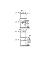
図1は本発明の金型格納装置2を示す斜視図である。
Hereinafter, the present invention will be described with reference to the accompanying drawings by embodiments.
FIG. 1 is a perspective view showing a
図1に示すプレスブレーキ1は、機械本体の両側に側板16、17を有し、該側板16、17の上部には、ラム駆動源である例えば油圧シリンダ14、15を介して上部テーブル12が取り付けられ、該上部テーブル12には、パンチホルダ30を介して一方の金型(より詳しくは分割金型)であるパンチPが装着されている。
A
また、側板16、17の下部には、下部テーブル13が配置され、該下部テーブル13には、ダイホルダ31を介して他方の金型(より詳しくは分割金型)であるダイDが装着されている。
A lower table 13 is disposed below the
この構成により、作業者Sは、下部テーブル13の後方に配置されたバックゲージの突当10、11にワークWを突き当てて位置決めした後、該作業者Sが例えばフットペダル7を踏み込むことにより、油圧シリンダ14、15を作動しラムである上部テーブル12を下降させれば、前記一対の金型であるパンチPとダイDの協働により該ワークWが曲げ加工される。
With this configuration, the worker S positions the work W against the
即ち、図1に示すプレスブレーキ1は、ラムである上部テーブル12が下降することにより、ワークWが曲げ加工される下降式プレスブレーキであり、図9、図11に示すプレスブレーキも同様であるが、本発明はこれに限定されず、ラムである下部テーブル13が上昇することにより、ワークWが曲げ加工される上昇式プレスブレーキでも差し支えない。
That is, the
上記パンチホルダ30とダイホルダ31は、いずれも後述する金型格納装置2側に若干突出しており、これによりプレスブレーキ1と金型格納装置2との間での金型交換(図7)が円滑に行われるようになっている。
Both of the
前記プレスブレーキ1の側方には、図1に示すように、金型格納装置2が設置されている。
As shown in FIG. 1, a
この場合、金型格納装置2は、上記プレスブレーキ1のパンチPとダイDを背中合わせに搭載した金型搭載用ストッカS1〜S8を複数個有する(例えば図 3)。
In this case, the
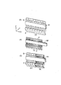
例えば、図3(A)に示すように、金型搭載用ストッカS1には、長尺金型CH(例えば長さ(X軸方向)が100mm)だけが、図3(B)に示すように、金型搭載用ストッカS2には、短尺金型TA(例えば長さ(X軸方向)が15mm、20mm、25mm、30mm、50mm、60mm、80mm等)だけが、図3(C)に示すように、金型搭載用ストッカS3には、既述した長尺金型CHと短尺金型TAが混在して、それぞれ所定の位置(X座標)に搭載されている。 For example, as shown in FIG. 3 (A), only the long mold CH (for example, the length (X-axis direction) is 100 mm) is included in the mold mounting stocker S1, as shown in FIG. 3 (B). As shown in FIG. 3C, only the short mold TA (for example, the length (X-axis direction) is 15 mm, 20 mm, 25 mm, 30 mm, 50 mm, 60 mm, 80 mm, etc.) is included in the mold mounting stocker S2. In addition, in the mold mounting stocker S3, the long mold CH and the short mold TA described above are mixedly mounted at predetermined positions (X coordinates).
従って、従来のように1つのストッカに一種類の金型、例えばパンチP又はダイDしか搭載できなかったので、パンチPとダイDを搭載するにはストッカが少なくとも2つ必要なのに比べれば、本発明によれば、前記したように、1つのストッカにパンチPとダイDが背中合わせに搭載できるので、パンチPとダイDを搭載するにはストッカが1つで済むので、ストッカの数を減少できる。 Accordingly, since only one type of mold, for example, punch P or die D, can be mounted on one stocker as in the prior art, compared to the case where at least two stockers are required to mount punch P and die D, this According to the invention, as described above, since the punch P and the die D can be mounted back to back on one stocker, only one stocker is required to mount the punch P and the die D, so the number of stockers can be reduced. .
既述したパンチPとダイDから成る金型、該金型P、Dを搭載するストッカS1〜S8、更には、プレスブレーキ1側の金型ホルダ30、31は、いずれもモジュラータイプであって、同じ構造を有し、詳細はWO00/41824号公報に開示されている。
The mold composed of the punch P and the die D, the stockers S1 to S8 on which the molds P and D are mounted, and the
上記金型搭載用ストッカS1〜S8は、既述した前記金型格納装置2(図1〜図2)に以下のような構成により取り付けられている。 The mold mounting stockers S1 to S8 are attached to the above-described mold storage device 2 (FIGS. 1 to 2) with the following configuration.
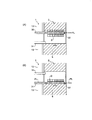
即ち、図4に示すように、金型搭載用ストッカ、例えばS1は、支持台41の前方(作業者S(図1)側)に固定され、該支持台41の両側(X軸方向)が無端ベルト8、9(図1)に支持されている。
That is, as shown in FIG. 4, a mold mounting stocker, for example, S1 is fixed in front of the support base 41 (worker S (FIG. 1) side), and both sides (X-axis direction) of the
上記支持台41は、上下方向(Z軸方向)から見ると、略コ字状形状を有し、横方向(X軸方向)に延びる部材41Aとその両端に直交する部材41B、41Cにより構成されている。
The
横方向部材41Aには既述した金型搭載用ストッカS1が固定され、直交部材41B、41Cには支軸42が軸受け43を介して回転自在に支持され、該支軸42は、前記無端ベルト8、9の外側(図4では下側)に固定されている。
The above-described mold mounting stocker S1 is fixed to the
この構成により、無端ベルト8(図2)、9が後述するプーリ32〜35、36〜39を介して循環し該無端ベルト8、9の向きが変わっても、例えば水平方向を向いても、上下方向を向いても、斜め方向を向いても、既述した支持台41と共にパンチPとダイDが搭載されたストッカS1〜S8が、重力の作用で常時下方を向くようになっている。
With this configuration, even if the endless belts 8 (FIG. 2) and 9 circulate through
従って、金型搭載用ストッカS1〜S8のうちの該当するストッカS1〜S8のパスラインPLの位置をプレスブレーキ1側の金型ホルダ30、31のパスラインPLの位置へ位置決めすることにより(図6〜図7)、金型交換が可能となる。
Accordingly, by positioning the position of the pass line PL of the corresponding stocker S1 to S8 among the mold mounting stockers S1 to S8 to the position of the pass line PL of the
一方、既述したように、金型搭載用ストッカS1〜S8の両端を支持する無端ベルト8(図1〜図2)、9は、プーリ32〜35、36〜39を介して循環するが、この場合の駆動軸は1軸である(図5)。
On the other hand, as described above, the endless belts 8 (FIGS. 1 to 2) and 9 that support both ends of the mold mounting stockers S1 to S8 circulate through the
例えば、プーリ32(図2)〜35、36〜39のうちのプーリ32を駆動プーリ32(図5)とし、該駆動プーリ32をモータMに直結すると共に連結軸40により対向するプーリ36と連結する。
For example, among the pulleys 32 (FIG. 2) to 35 and 36 to 39, the
この構成により、モータMを作動すれば、駆動プーリ32が回転し、その回転力は無端ベルト8を通じて他の従動プーリ33、34、35に伝達され、また、連結軸40に連結されたプーリ36が駆動プーリとなって前記駆動プーリ32と同時回転し、同様にその回転力は無端ベルト9を通じて他の従動プーリ37、38、39に伝達される。
With this configuration, when the motor M is operated, the driving
よって、無端ベルト8、9は、金型搭載用ストッカS1〜S8を支持しながら円滑に循環し、例えば既述したように、金型搭載用ストッカS1〜S8のうちの該当するストッカS1〜S8のパスラインPLの位置をプレスブレーキ1側の金型ホルダ30、31のパスラインPLの位置へ位置決めすることにより(図6)、金型交換(図7)が可能となる。
Therefore, the
上記パスラインPL(図6〜図7)は、金型P、Dの移動基準線であって、金型搭載用ストッカS1〜S8と金型ホルダ30、31とは、既述したように同じ構造を有することから、各パスラインPLを同じ高さ位置に位置決めしておけば、金型搭載用ストッカS1〜S8と金型ホルダ30、31間の金型P、D移動が極めて円滑に行われ、前記したように、金型交換(図7)が可能となる。
The pass line PL (FIGS. 6 to 7) is a movement reference line for the molds P and D, and the mold mounting stockers S1 to S8 and the
本発明によれば、前記無端ベルト8、9は、駆動軸が1軸であることから、従来と比べて構成が簡単であり、また設置スペースも少なくて済む。
According to the present invention, since the
また、本発明によれば、前記無端ベルト8(図1〜図2)、9は、循環する際には、作業者S側に金型搭載用ストッカS1〜S8がはみ出さないようになっており、これにより、作業者Sによる金型交換が容易に行われることが可能となる。 According to the present invention, when the endless belts 8 (FIGS. 1 to 2) and 9 circulate, the mold mounting stockers S1 to S8 do not protrude from the worker S side. Thus, the mold exchange by the worker S can be easily performed.
尚、上記無端ベルト8(図1〜図2)、9とプーリ32〜35、36〜39の代わりに無端チェーンとスプロケットを用いても差し支えない。
An endless chain and a sprocket may be used instead of the endless belts 8 (FIGS. 1 to 2) and 9 and the
更に、上記金型格納装置2の前部と後部にはシャッタ5、6が設けられている。
Furthermore,
即ち、金型格納装置2(図1)全体は、フレームの外側が透明なケースで覆われており(一点鎖線)、これにより作業者Sの安全が確保されているが、前部と後部には、前記したようにシャッタ5、6が設けられており、必要に応じて開閉するようになっている。
That is, the entire mold storage device 2 (FIG. 1) is covered with a transparent case on the outer side of the frame (a chain line), thereby ensuring the safety of the worker S. As described above, the
例えば、該当するストッカS1〜S8のパスラインPLの位置をプレスブレーキ1側の金型ホルダ30、31のパスラインPLの位置へ位置決めする場合や(図6)金型交換時(図7)には、前部シャッタ5は最下位置に下降しておくことにより、上記各動作が作業者Sにとって目視で確認できるようになっている。
For example, when the position of the pass line PL of the corresponding stockers S1 to S8 is positioned to the position of the pass line PL of the
また、前部シャッタ5(図8(A))は、曲げ加工時には最下位置まで下降し、前部中央部を開放した状態でストッカ無し領域を形成することにより、加工済みのワークの横抜きを可能としてある。 Further, the front shutter 5 (FIG. 8A) descends to the lowest position during bending, and forms a no-stocker area with the front central part opened, so that the processed workpiece can be cut out horizontally. Is possible.
更に、前部シャッタ5(図8(B))は、ストッカ移動時には最下位置から上昇して前部中央部を閉鎖することにより、作業者Sの安全を確保している。 Furthermore, the front shutter 5 (FIG. 8 (B)) is secured from the lowermost position when moving the stocker and closes the front central portion to ensure the safety of the operator S.
一方、後部シャッタ6(図2)は、最下位置まで下降することにより、段取りステーションを形成するようになっている。 On the other hand, the rear shutter 6 (FIG. 2) is lowered to the lowest position to form a setup station.
また、金型交換時において(図7)、作業者S(図1)は、パンチP交換の場合には(図7(A))、長尺金型(例えば100mm)は、比較的重いので、取り出さずに金型搭載用ストッカS1からパンチホルダ30側へそのまま横移動させ(矢印(1))、短尺金型(例えば50mm)は、比較的軽いので、金型搭載用ストッカS1から取り出してパンチホルダ30側の所定位置へ配置させる(矢印(2))。 Further, at the time of changing the mold (FIG. 7), the operator S (FIG. 1), when replacing the punch P (FIG. 7A), the long mold (for example, 100 mm) is relatively heavy. Without taking out, the die mounting stocker S1 is moved laterally as it is toward the punch holder 30 (arrow (1)), and the short die (for example, 50 mm) is relatively light, so it is taken out from the die mounting stocker S1. It arrange | positions to the predetermined position by the side of the punch holder 30 (arrow (2)).
このことは、ダイD交換の場合にも(図7(B))、同様である。 This is the same in the case of die D exchange (FIG. 7B).
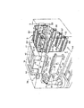
図9は、本発明による金型・ハンド格納装置3を示す斜視図である。
図1に示す金型格納装置2との全体的な相違点は、金型・ハンド格納装置3が、金型搭載用ストッカのみならずハンド搭載用ストッカも備える点である。
以下の実施例においては、上記プレスブレーキ1のパンチPとダイDを背中合わせに搭載した金型搭載用ストッカを有する金型・ハンド格納装置3(図9〜図10)について詳述する。
また、図1の金型格納装置2と図9の金型・ハンド格納装置3との具体的な相違点については、後述する第1〜第4の相違点で明らかにする。
FIG. 9 is a perspective view showing the mold /
The overall difference from the
In the following embodiments, the mold / hand storage device 3 (FIGS. 9 to 10) having a mold mounting stocker in which the punch P and the die D of the
Further, specific differences between the
上記図9の金型・ハンド格納装置3は、隣接するプレスブレーキ1と共に、安全柵70(一点鎖線)で包囲されていて安全が確保されている。
The mold /
但し、金型・ハンド格納装置3の後方には安全柵70は無く、その代わりに該金型・ハンド格納装置3に後部シャッタ6(図9〜図10)が設けられ、必要なときには後部シャッタ6を最下位置まで下降させることにより、金型やハンドについて段取りを行うようになっている(図17のステップ101)。
However, the
この金型・ハンド格納装置3は、前記図1の金型格納装置2とは、プレスブレーキ1の側方に設置されている点(図9)、パンチPとダイ31を背中合わせに搭載した金型搭載用ストッカS1(図3に相当)、S3〜S4、S6〜S8を有する点、無端ベルト8、9の駆動軸が1軸(図5に相当)である点、上記金型搭載用ストッカS1、S3〜S4、S6〜S8のうちの該当するストッカのパスラインPLの位置をプレスブレーキ1側の金型ホルダ30、31のパスラインPLの位置へ位置決め自在とする(図6)点等、共通点があるが、以下に述べるように、著しい相違点もある。
This mold /
第1の相違点は、プレスブレーキ1と金型・ハンド格納装置3の前方を曲げロボット4が長手方向(X軸方向)に移動自在に設置されている点である。
A first difference is that a bending
即ち、曲げロボット4は、図9に示すように、レール52、53上を長手方向に移動自在であって、アーム50の先端に雄型コネクタ54を有している。
That is, as shown in FIG. 9, the bending
図11は、前記曲げロボット4と後述するワーク把持ハンド57(図12)又は金型交換ハンド58(図13)との着脱機構を示す図である。
FIG. 11 is a view showing an attaching / detaching mechanism between the bending
曲げロボット4側の雄型コネクタ54は例えば円柱59を有し、該円柱59に沿って複数個のボール51が設けられている。
The
これに対して、ハンド57(58)側の雌型コネクタ55は、前記曲げロボット4側の雄型コネクタ54の円柱59が挿入する円溝60を有し、該円溝60の内部には前記雄型コネクタ54の複数個のボール51に対応する穴56が複数個設けられている。
On the other hand, the
この構成により、曲げロボット4の雄型コネクタ54側の円柱59がハンド57(58)の雌型コネクタ55側の円溝60に挿入した後、円柱59の周囲のボール51が突出して円溝60内の穴56に受容され、これにより、曲げロボット4はハンド57(58)を装着することができる(所謂ボール・ロック方式)。
With this configuration, after the
反対に曲げロボット4がハンド57(58)を離脱させる場合には、前記穴56(図11)に受容されているボール51を引っ込めた後、円柱59を円溝60から引き抜けば良い。
On the contrary, when the bending
次に、第2の相違点は、金型・ハンド格納装置3(図9)が、既述した曲げロボット4が使用するハンド57(58)を搭載するハンド搭載用ストッカS2、S5を有する点である。
Next, the second difference is that the mold / hand storage device 3 (FIG. 9) includes the hand mounting stockers S2 and S5 on which the hand 57 (58) used by the bending
即ち、曲げロボット4が使用するハンドとしては、ワーク把持ハンド57と金型交換ハンド58とに大別される。
In other words, the hands used by the bending
ワーク把持ハンド57は、曲げロボット4がプレスブレーキ1(図9)による曲げ加工対象であるワークWを把持する場合のハンドであり、把持すべきワークWの形態に応じてバキュームパッド(図12)であったり、ジョーであったりする。
The
また、金型交換ハンド58は、曲げロボット4が金型交換を行う場合(図14〜図16)に使用するハンドであり、よく知られているように、既述したモジュラータイプの金型の落下防止部材(WO00/41824号公報に開示)を押圧する鉤部材(図13)と金型移動に必要な係合部材を有する。
The
以下の実施例では、上記ワーク把持ハンド57と金型交換ハンド58とをそれぞれ別のストッカに搭載しており、図12は、ワーク把持ハンド搭載用ストッカS2を、図13は、金型交換ハンド搭載用ストッカS5を示している。
又は、このように別々のストッカS2、S5を準備することなく、ワーク把持ハンド57と金型交換ハンド58とを、ストッカに混在させても良く、この場合には、曲げロボット4がそのハンドを金型交換ハンド58へ交換するときや(例えば図17のステップ105)ワーク把持ハンド57へ交換するとき(例えば図17のステップ111)にも、ワーク把持ハンド57と金型交換ハンド58とが混在したストッカだけをハンド交換位置HCPに位置決めすれば足りるので(例えば図18(A)だけで図18(C)は不要となる。)、ハンド交換がより一層迅速に行われる。そして、この場合も、上記混在するストッカには、後述する固定手段64(図12〜図13)と同様の固定手段が設けられ、ストッカ上に混在する各ハンドが落下しないようになっている。
In the following embodiments, the
Alternatively, without preparing the separate stockers S2 and S5 as described above, the
上記ワーク把持ハンド搭載用ストッカS2(図12)は、ワーク把持ハンド57を搭載し長手方向(X軸方向)に延びる搭載部61と、無端ベルト8、9に支持され上下方向(Z軸方向)に延びる支持部62、63により構成されている。
The workpiece gripping hand mounting stocker S2 (FIG. 12) is mounted on the
上記搭載部61には、ワーク把持ハンド57をしっかり固定する固定手段64(例えば電磁石)が設けられ、無端ベルト8、9を循環させる際にも(図10)、ワーク把持ハンド57がストッカS2から落下しないようになっている。
The mounting
また、ワーク把持ハンド57への交換時(図17のステップ111)には、曲げロボット4が不要な金型交換ハンド58をストッカS5(図13)に戻した後、そのアーム50(図11)の雄型コネクタ54をストッカS2(図12)に搭載されたワーク把持ハンド57の雌型コネクタ55に挿入して両者をロックさせれば、その時点で固定手段64である電磁石は消磁され、曲げロボット4は前記ワーク把持ハンド57を迅速に取り出すことができる。
When replacing the workpiece gripping hand 57 (
一方、支持部62、63と無端ベルト8、9との関係は、既述した(図4)金型搭載用ストッカS1〜S8が固定されている支持台41の直交部材41B、41Cと無端ベルト8、9との関係と同じである。
On the other hand, the relationship between the
即ち、上記ワーク把持ハンド搭載用ストッカS2(図12)の支持部62、63には、支軸42が軸受け43を介して回転自在に支持され、該支軸42は、前記無端ベルト8、9の外側(図12では上側)に固定されている。
That is, the
この構成により、無端ベルト8、9が同様にプーリ32〜35、36〜39を介して循環し該無端ベルト8、9の向きが変わっても、例えば水平方向を向いても、上下方向を向いても、斜め方向を向いても、前記ワーク把持ハンド57が搭載されたストッカS2が、重力の作用で常時下方を向くようになっている。
With this configuration, the
従って、ワーク把持ハンド搭載用ストッカS2をハンド交換位置HCPへ位置決めすることにより(図17のステップ110)、ワーク把持ハンド57への交換が可能となる(図17のステップ111)。
Therefore, by positioning the work gripping hand mounting stocker S2 to the hand replacement position HCP (
一方、金型交換ハンド搭載用ストッカS5(図13)は、金型交換ハンド58を搭載し同様に長手方向(X軸方向)に延びる搭載部61と、無端ベルト8、9に支持され同様に上下方向(Z軸方向)に延びる支持部62、63により構成されている。
On the other hand, the mold exchange hand mounting stocker S5 (FIG. 13) is supported by the
上記搭載部61には、同様に金型交換ハンド58をしっかり固定する固定手段64(例えば電磁石)が設けられ、無端ベルト8、9を循環させる際にも(図10)、金型交換ハンド58がストッカS5から落下しないようになっている。
Similarly, the mounting
また、金型交換ハンド58への交換時(図17のステップ103)には、曲げロボット4が不要なワーク把持ハンド57をストッカS2(図12)に戻した後、そのアーム50(図11)の雄型コネクタ54をストッカS5(図13)に搭載された金型交換ハンド58の雌型コネクタ55に挿入して両者をロックさせれば、その時点で固定手段64である電磁石は消磁され、曲げロボット4は前記金型交換ハンド58を迅速に取り出すことができる。
Further, at the time of exchanging with the mold exchanging hand 58 (step 103 in FIG. 17), the bending
一方、支持部62、63と無端ベルト8、9との関係は、同様に、既述した(図4)金型搭載用ストッカS1〜S8が固定されている支持台41の直交部材41B、41Cと無端ベルト8、9との関係と同じである。
On the other hand, the relationship between the
即ち、上記金型交換ハンド搭載用ストッカS5(図13)の支持部62、63には、支軸42が軸受け43を介して回転自在に支持され、該支軸42は、前記無端ベルト8、9の外側(図13では下側)に固定されている。
That is, the
この構成により、無端ベルト8、9が同様にプーリ32〜35、36〜39を介して循環し該無端ベルト8、9の向きが変わっても、例えば水平方向を向いても、上下方向を向いても、斜め方向を向いても、前記金型交換ハンド58が搭載されたストッカS5が、重力の作用で常時下方を向くようになっている。
With this configuration, the
従って、金型交換ハンド搭載用ストッカS5をハンド交換位置HCPへ位置決めすることにより(図17のステップ104)、金型交換ハンド58への交換が可能となる(図17のステップ105)。
Accordingly, by positioning the mold exchange hand mounting stocker S5 to the hand exchange position HCP (step 104 in FIG. 17), the
更に、第3の相違点は、金型・ハンド格納装置3(図9)の場合には、作業者S(図1)ではなくて、曲げロボット4(図9、図10)が金型交換や(図17のステップ107)曲げ加工(図17のステップ112)を行うことから、各ストッカS1〜S8(図10)が曲げロボット4側にはみ出ないように前記無端ベルト8、9が循環する点であり、第4の相違点は、金型・ハンド格納装置3(図9)が、既述したように、金型搭載用ストッカの他にハンド搭載用ストッカS2、S5を有することから、該ハンド搭載用ストッカS2、S5のうちの該当するストッカS2、S5をハンド交換位置HCPへ位置決め自在とした点である(図17のステップ102、104、図17のステップ108、110)。
Furthermore, the third difference is that in the case of the mold / hand storage device 3 (FIG. 9), the bending robot 4 (FIGS. 9 and 10) replaces the mold instead of the operator S (FIG. 1). (
図14〜図16は、いずれもプレスブレーキ1側の金型ホルダ30、31において、曲げロボット4の金型交換ハンド58により金型がどのように装着されるかを表しており、これらの元は、いずれも金型レイアウトa(図21)、b、c、dであり、後で詳述する。
14 to 16 show how the mold is mounted by the
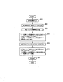
以下、上記構成を有する金型・ハンド格納装置3(図9)を使用するロボットによる金型交換方法を図17に基づいて説明する。 Hereinafter, a die replacement method by a robot using the die / hand storage device 3 (FIG. 9) having the above configuration will be described with reference to FIG.
(1)段取り動作。
先ず、図17のステップ101において、段取りが行われる。
(1) Setup operation.
First, in
即ち、金型交換や曲げ加工を行う前に、作業者S(図1)は、金型・ハンド格納装置3(図9、図11)の後部シャッタ6を最下位置まで下降させることにより、内部のストッカS1〜S8へ必要な金型及びハンド、又は金型、若しくはハンドを予め搭載しておく。
That is, before performing mold replacement or bending, the operator S (FIG. 1) lowers the
換言すれば、本番前に金型とハンドについて漏れが無いか、予め準備をしておくということである。 In other words, it is necessary to prepare in advance whether there is no leakage of the mold and the hand before the actual production.
(2)曲げロボット4のハンドをワーク把持ハンド57から金型交換ハンド58へ交換するまでの動作。
(2) Operation until the hand of the bending
次に、図17のステップ102において、ワーク把持ハンド搭載用ストッカS2を位置決めし、ステップ103において、不要なワーク把持ハンド57を戻し、ステップ104において、金型交換ハンド搭載用ストッカS5を位置決めし、ステップ105において、金型交換ハンド58へ交換する。
Next, in
即ち、最初に、ワーク把持ハンド搭載用ストッカS2(図18(A))をハンド交換位置HCPに位置決めし、次に、曲げロボット4(図18(B))が持っているワーク把持ハンド57を上記ハンド交換位置HCPに位置決めしたストッカS2に戻す。
That is, first, the workpiece gripping hand mounting stocker S2 (FIG. 18A) is positioned at the hand replacement position HCP, and then the
上記ハンド交換位置HCPは、曲げロボット4とワーク把持ハンド搭載用ストッカS2又は金型交換ハンド搭載用ストッカS5との間でハンドを交換する場合の位置であり、予め設定しておく。
The hand exchange position HCP is a position for exchanging hands between the bending
次いで、上記曲げロボット4が不要なワーク把持ハンド57をストッカS2(図18(B))に戻した後は、もう一方の金型交換ハンド搭載用ストッカS5(図18(C))をハンド交換位置HCPに位置決めし、再度曲げロボット4自らが必要となった金型交換ハンド58を該金型交換ハンド搭載用ストッカS5から取り出す(図18(D))。
Next, after the
このようにして、曲げロボット4は、自己が所有するハンドをワーク把持ハンド57から金型交換ハンド58へ交換する。
In this way, the bending
(3)金型交換動作。 (3) Mold exchange operation.
図17のステップ106において、金型搭載用ストッカを位置決めし、ステップ107において、金型交換を行う。
In
即ち、今度は金型搭載用ストッカS1(図9、図10)、S3〜S4、S6〜S8のうちの該当するストッカのパスラインPLの位置をプレスブレーキ1側の金型ホルダ30、31のパスラインPLの位置に位置決めし(図6に相当)、その後、前記金型交換ハンド58(図18(D))を有する曲げロボット4が、該当するストッカの所定位置にある金型P、Dを取り出して(WO00/41824号公報に開示)、プレスブレーキ1側の金型ホルダ30、31の所定位置に移動させることにより、金型交換が行われる(図7に相当)。
That is, this time, the position of the pass line PL of the corresponding stocker among the mold mounting stockers S1 (FIGS. 9 and 10), S3 to S4, and S6 to S8 is set to the die
(4)曲げロボット4のハンドを金型交換ハンド58からワーク把持ハンド57へ交換するまでの動作。
(4) Operation until the hand of the bending
図17のステップ108において、金型交換ハンド搭載用ストッカS5を位置決めし、ステップ109において、不要な金型交換ハンド58を戻し、ステップ110において、ワーク把持ハンド搭載用ストッカS2を位置決めし、ステップ111において、ワーク把持ハンド57へ交換する。
In
即ち、この場合の動作は前記した図18に相当するものであり、最初に、金型交換ハンド搭載用ストッカS5をハンド交換位置HCPに位置決めし(図18(A)に相当)、次に、曲げロボット4が持っている金型交換ハンド58を上記ハンド交換位置HCPに位置決めしたストッカS5に戻す(図18(B)に相当)。
That is, the operation in this case corresponds to FIG. 18 described above. First, the mold replacement hand mounting stocker S5 is positioned at the hand replacement position HCP (corresponding to FIG. 18A), and then The
次いで、上記曲げロボット4が不要な金型交換ハンド58をストッカS5(図18(B)に相当)に戻した後は、もう一方のワーク把持ハンド搭載用ストッカS2をハンド交換位置HCPに位置決めし(図18(C)に相当)、再度曲げロボット4自らが必要となったワーク把持ハンド57を該ワーク把持ハンド搭載用ストッカS2から取り出す(図18(D)に相当)。
Next, after the
このようにして、曲げロボット4は、自己が所有するハンドを金型交換ハンド58からワーク把持ハンド57へ交換する。
In this way, the bending
(5)曲げ加工動作。
図17のステップ112において、曲げ加工が行われる。
(5) Bending operation.
In
即ち、曲げロボット4(図9〜図10)はワーク把持ハンド57でワークWを把持すると、曲げ順(工程)ごとに該当する加工ステーションまで移動し、パンチPとダイDの間から把持したワークWを供給してバックゲージの突当10、11に付き当てて位置決めした後、油圧シリンダ14、15の作用で上部テーブル12が下降し前記パンチPとダイDの協働によりワークWが曲げ加工される。
That is, when the bending robot 4 (FIGS. 9 to 10) grips the workpiece W with the
本発明は、曲げ加工が終了するまで図17の動作を繰り返す。 The present invention repeats the operation of FIG. 17 until the bending process is completed.
図19は、ロボットによる金型交換方法(図17〜図18)の実施に直接使用する制御装置を示す図である。 FIG. 19 is a diagram showing a control device used directly for carrying out the die changing method (FIGS. 17 to 18) by the robot.
上記制御装置は、NC装置20により構成され、該NC装置20は、CPU20Aと、入力部20Bと、記憶部20Cと、金型レイアウト決定部20Dと、金型・ハンド搭載情報決定部20Eと、金型・ハンド格納装置制御部20Fと、ハンド交換制御部20Gと、金型交換制御部20Hと、曲げ加工制御部20Jにより構成されている。
The control device includes an
CPU20Aは、本発明を実施するための動作手順(例えば図24に相当)に従って金型レイアウト決定部20D、金型・ハンド搭載情報決定部20Eなど図19に示す装置全体を統括制御する。
The
入力部20Bは、プレスブレーキ1に取り付けられている操作盤を構成し、よく知られているように、キーボードなどを有し、この操作盤20Bを用いて例えば自動又は手動により、製品情報などを入力することができ、入力結果は画面で確認できる。
The
上記製品情報は、例えばCAD(Computer Aided Design)情報であり、ワークW(図20)の板厚、材質、曲げ線m1〜m4の長さL1〜L4、曲げ角度、フランジF1〜F4の寸法などの情報を含み、これらが立体姿図、展開図として構成されている。 The product information is, for example, CAD (Computer Aided Design) information, and the thickness and material of the workpiece W (FIG. 20), the lengths L1 to L4 of the bending lines m1 to m4, the bending angle, the dimensions of the flanges F1 to F4, and the like. These are configured as a three-dimensional view and a development view.
上記記憶部20Cは(図19)、本発明を実施するためのプログラムを記憶する他、後述する金型レイアウト決定部20Dが決定した曲げ順、曲げ順ごとの金型、金型レイアウトなど(図21)、また、金型・ハンド搭載情報決定部20Eが決定した金型・ハンド搭載情報(図22)をデータベースとして記憶する。
The
金型レイアウト決定部20Dは(図19)、前記入力部20Bを介して入力された製品情報に基づいて、曲げ順(1)、(2)、(3)、(4)を決定すると共に、各曲げ順ごとにワークWを加工する金型及び金型レイアウトa、b、c、dを決定する(図24のステップ101〜ステップ102)。
The mold
例えば、図20に示すように、平坦なワークWの曲げ線m1、m2、m3、m4部分を(1)、(2)、(3)、(4)の順に曲げ加工し、最終的には、図示するように、フランジF1、F2、F3、F4が立った製品を加工するものとすると、金型レイアウト決定部20Dが(図19)曲げ順などを決定した結果が、図21に示されている。
For example, as shown in FIG. 20, the bending lines m1, m2, m3, and m4 of the flat work W are bent in the order of (1), (2), (3), and (4), and finally As shown in FIG. 21, when a product with flanges F1, F2, F3, and F4 is to be processed, the result of the mold
図21においては、曲げ順ごとに、各加工ステーションST1、ST2内の各位置X1、X2・・・・に配置された金型(○印)から成る金型レイアウトa、b、c、dが示されているが、本発明による金型レイアウトの例としては、既述した図14〜図16に示すものがある。 In FIG. 21, for each bending order, mold layouts a, b, c, d composed of molds (circles) arranged at positions X1, X2,... In each processing station ST1, ST2. Although shown, examples of the mold layout according to the present invention include those shown in FIGS.
即ち、図14(A)は、パンチホルダ30に対して、パンチPが表付けされた場合であり、図14(B)は、同ホルダ30に対して、パンチPが裏付けされた場合である。
14A shows a case where the punch P is attached to the
また、図15(A)は、ダイホルダ31に対して、パンチPが裏付けされた場合であり、図15(B)は、同ホルダ31に対して、パンチPが表付けされた場合である。
15A shows a case where the punch P is backed against the
更に、図16(A)は、パンチホルダ30に対して、ダイDが表付けされた場合であり、図16(B)は、ダイホルダ31に対して、ダイDが表付けされた場合である。
Further, FIG. 16A is a case where the die D is attached to the
一般に、金型レイアウトは、どのような断面形状(図23)、どのような長さ(X軸方向(mm))の金型を金型ホルダ30、31のどの位置に配置するかといったことだけではなく、ワークWと金型との干渉やワークWと上部テーブル12、下部テーブル13との干渉といったことも考慮しなくてはならない。
In general, the die layout is only about what cross-sectional shape (FIG. 23) and what length (X-axis direction (mm)) the die is placed in which position of the
従って、上記図14(B)のように、パンチPがパンチホルダ30に裏付けされたり、図15(A)のように、ダイホルダ31に対して、パンチPが裏付けされたり、図15(B)のように、ダイホルダ31に対して、パンチPが表付けされたり、図16(A)のように、パンチホルダ30に対して、ダイDが表付けされたりする場合がある。
Accordingly, the punch P is backed by the
一方、上記金型・ハンド搭載情報決定部20E(図19)は、前記金型レイアウト決定部20Dにより決定された金型レイアウトa(図21)、b、c、dを構成する金型P、Dが、金型・ハンド格納装置3(図9、図19)のどのストッカS1、S3〜S4、S6〜S8のどの位置に搭載されているか、また、ワークWを把持する場合と金型P、Dを交換する場合に曲げロボット4が具備すべきハンドが、どのストッカS2、S5のどの位置に搭載されているかを表す金型・ハンド搭載情報を決定する。
On the other hand, the mold / hand mounting
この場合、上記金型・ハンド搭載情報決定部20E(図19)は、例えば入力部20Bと記憶部20Cにより構成され、金型・ハンド搭載情報は作業者Sが入力部20Bから入力し、記憶部20Cにデータベースとして記憶される。
又は、上記金型・ハンド搭載情報決定部20E(図19)は、ストッカ内の金型・ハンド位置検出手段として、例えばノギス等において既に知られている複数個の静電容量型の位置検出センサ等を左右方向に配置して備え、上記金型・ハンド搭載情報を自動的に記憶部20Cにデータベースとして記憶しても良い。
In this case, the mold / hand mounting
Alternatively, the mold / hand mounting
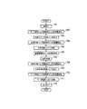
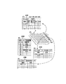
即ち、金型・ハンド搭載情報の具体例としては、例えば図22に示されている。 That is, a specific example of the mold / hand mounting information is shown in FIG. 22, for example.
先ず、図22(A)は、金型・ハンド格納装置3(図9、図19)内のストッカS1〜S8を示し、そのうちS1、S3〜S4、S6〜S8は金型搭載用ストッカであり、S2、S5は、ハンド搭載用ストッカである(そのうちS2はワーク把持ハンド搭載用ストッカ、S5は金型交換ハンド搭載用ストッカである)。 First, FIG. 22A shows stockers S1 to S8 in the mold / hand storage device 3 (FIGS. 9 and 19), among which S1, S3 to S4, and S6 to S8 are mold mounting stockers. , S2 and S5 are hand mounting stockers (of which S2 is a workpiece gripping hand mounting stocker and S5 is a mold exchange hand mounting stocker).
そして、図22(B)は、前記ストッカS1〜S8(図22(A))のどのストッカにどのような部材が搭載されているかを表す金型・ハンド格納装置3の全体情報である。
FIG. 22B shows the whole information of the mold /
例えば、ストッカS1(図9、図10)、S3〜S4、S6〜S8には、パンチPとダイDから成る金型(背中合わせ)が、ストッカS2には、ワーク把持ハンド57が、S5には、金型交換ハンド58がそれぞれ搭載されている。
For example, stockers S1 (FIGS. 9 and 10), S3 to S4, and S6 to S8 have molds (back-to-back) composed of punches P and dies D, stockers S2 have
また、図22(C)は、金型を搭載しているストッカS1の詳細な情報である。 FIG. 22C shows detailed information of the stocker S1 on which the mold is mounted.
例えば、ストッカS1の金型搭載情報は、パンチについては、断面形状がサッシ形状(図23)であって、表付けか裏付けか、長さ(X軸方向(mm))、位置(ストッカS1におけるX軸方向の座標)はどうか、また、ダイについては、断面形状が1V形状(図23)であって、表付けか裏付けか、長さ(X軸方向(mm))、位置(ストッカS1におけるX軸方向の座標)はどうかといった情報である。
尚、これら詳細な金型搭載情報には、既述した金型・ハンド位置検出手段と同様に(前記段落番号〔0124〕の後半参照)、金型に備えたバーコード、ICチップ等の金型識別媒体から別途設けた金型識別媒体読み取り手段により前記記憶部20C(図19)に自動的に記憶された情報も含まれる。
For example, the die mounting information of the stocker S1 is that the punch has a sash shape (FIG. 23), and is attached or supported, length (X-axis direction (mm)), position (in the stocker S1) What is the coordinate in the X-axis direction? Also, for the die, the cross-sectional shape is 1V shape (FIG. 23), and whether it is front or back, length (X-axis direction (mm)), position (in stocker S1) Information on the coordinate in the X-axis direction).
The detailed mold mounting information includes the barcode, IC chip and other molds provided in the mold in the same manner as the mold / hand position detecting means described above (see the latter half of paragraph [0124]). Information automatically stored in the
これらの情報の元は、前記金型レイアウト決定部20D(図19)により決定された金型レイアウトa(図21)、b、c、dであり、例えば表付けか裏付けかといった情報は、このストッカS1に搭載されている金型の状態を表している。
The sources of these information are the mold layouts a (FIG. 21), b, c, and d determined by the mold
上記図22(C)において、パンチが表付けとなっている場合には、ストッカS1にパンチが表付けで搭載されていることを表している。 In FIG. 22C, when the punch is attached, it indicates that the punch is mounted on the stocker S1.
従って、プレスブレーキ1側のパンチホルダ30(例えば図14(A))にパンチPを表付けするときには、曲げロボット4は、前記金型・ハンド格納装置3のストッカS1に表付けに搭載されたパンチをそのまま取り出せば良い。
Therefore, when mounting the punch P on the punch holder 30 (for example, FIG. 14A) on the
しかし、ストッカS1に搭載されている金型の情報としては、この表付けか裏付けかといったことは、必ずしも必要ではない。 However, it is not always necessary for the information on the mold mounted on the stocker S1 to be attached or supported.
例えば、ストッカS1に搭載されている段階では、パンチを全て一律に表付けにしていても、曲げロボット4がプレスブレーキ1側のパンチホルダ30(図14)にパンチPを装着する時点で、金型レイアウトa、b、c、d(図21)を参照して判断し、直前にパンチPを表裏反転すれば、図14(B)に示すように、裏付けにすることができる。
For example, when the punch is mounted on the stocker S1, even when all the punches are uniformly attached, the bending
上記図22(C)は、金型を搭載しているストッカS1の詳細な情報であるが、他のストッカS3〜S4、S6〜S8についても同様である。 FIG. 22C shows detailed information of the stocker S1 on which the mold is mounted, but the same applies to the other stockers S3 to S4 and S6 to S8.
上記図22の金型・ハンド搭載情報としての断面形状(図22(C))には、図示する以外にも、パンチ(図23)については、標準形状、直剣形状、グーズネック形状等があり、ダイについては、厚板形状等があり、これらも既述した金型レイアウト決定部20D(図19)により決定された金型レイアウトa(図21)、b、c、dに基づくものである。
In addition to the cross-sectional shape (FIG. 22C) as the mold / hand mounting information in FIG. 22 above, there are standard shapes, straight sword shapes, gooseneck shapes, etc. for the punch (FIG. 23). The die has a thick plate shape, etc., which are also based on the mold layout a (FIG. 21), b, c, d determined by the mold
図22(D)は、ワーク把持ハンド57を搭載しているストッカS2の詳細な情報である。
FIG. 22D shows detailed information of the stocker S2 on which the
例えば、ストッカS2のワーク把持ハンド搭載情報は、種別が、バキュームパッドか、ジョーか等、また位置(ストッカS2におけるX軸方向の座標)はどうかといった情報である。 For example, the workpiece gripping hand mounting information of the stocker S2 is information such as whether the type is a vacuum pad or a jaw, and the position (the coordinate in the X-axis direction in the stocker S2).
この場合、曲げロボット4がどの種別のワーク把持ハンドを取り付けるかといったことは、曲げ加工対象であるワークWの形態に基づくものであり、該ワークWを把持し易いといった観点から定まる。
In this case, the type of work gripping hand to be attached by the bending
図22(E)は、金型交換ハンド58を搭載しているストッカS5の詳細な情報である。
FIG. 22E shows detailed information of the stocker S5 on which the
例えば、ストッカS5の金型交換ハンド搭載情報は、種別が、モジュールか否か等、また位置(ストッカS2におけるX軸方向の座標)はどうかといった情報である。 For example, the die exchange hand mounting information of the stocker S5 is information such as whether the type is a module or not, and the position (coordinate in the X-axis direction in the stocker S2).
この場合、曲げロボット4がどの種別の金型交換ハンドを取り付けるかといったことは、交換対象である金型の形態に基づくものであり、該金型がモジュール(WO00/41824号公報に開示)か否かといった観点から定まる。
In this case, what type of mold exchanging hand is attached by the bending
上記図22の金型・ハンド搭載情報は、作業者Sが金型交換や曲げ加工の前の段取り工程において判明しており、従って、予め入力部20B(図19)の画面から入力しておくことにより、記憶部20Cにデータベースとして記憶される。
The mold / hand mounting information in FIG. 22 is known by the operator S in the setup process before the mold replacement and bending, and is therefore input in advance from the screen of the
上記記憶部20Cに記憶された金型・ハンド搭載情報(図22)は、後述する金型・ハンド格納装置制御部20F(図19)、ハンド交換制御部20G、金型交換制御部20Hが駆動する場合に参照する。
The mold / hand mounting information (FIG. 22) stored in the
上記金型・ハンド格納装置制御部20F(図19)は、上記決定された金型レイアウトa、b、c、dと金型・ハンド搭載情報に基づき、曲げロボット4が必要とすべきハンド57、58と金型は何かを判断し、ハンド搭載用ストッカS2、S5のうちの該当するストッカをハンド交換位置HCPへ位置決めさせ、又は金型搭載用ストッカS1、S3〜S4、S6〜S8のうちの該当するストッカのパスラインPLの位置をプレスブレーキ1側の金型ホルダ30、31のパスラインPLの位置へ位置決めする。
The mold / hand
また、上記ハンド交換制御部20G(図19)は、ハンド搭載用ストッカS2、S5のうちの該当するストッカと、前記曲げロボット4との間で、曲げロボット4を介して、ハンドの交換を行わせる。
Further, the hand
更に、上記金型交換制御部20H(図19)は、金型搭載用ストッカS1、S3〜S4、S6〜S8のうちの該当するストッカと、プレスブレーキ1側の金型ホルダ30、31との間で、曲げロボット4を介して、金型の交換を行わせる。
Further, the mold
次いで、上記曲げ加工制御部20J(図19)は、金型交換制御部20Hを用いた曲げロボット4による金型交換後、ラム駆動源14、15を作動させ、該曲げロボット4がワーク把持ハンド58で把持しプレスブレーキ1へ供給したワークWをパンチPとダイDで曲げ加工させる。
Next, the bending
これら上記金型・ハンド格納装置制御部20F、ハンド交換制御部20G、金型交換制御部20H、曲げ加工制御部20Jは、後述するように、図24のステップ204〜ステップ207における動作の主体としての役割を演じる。
These mold / hand storage
以下、上記構成を有する本発明の動作を、図24に基づいて説明する。
(1)金型・ハンド搭載情報を決定するまでの動作。
The operation of the present invention having the above configuration will be described below with reference to FIG.
(1) Operation until the mold / hand mounting information is determined.
図24のステップ201において、製品情報を入力し、ステップ202において、曲げ順、金型、金型レイアウトを決定し、ステップ203において、金型・ハンド搭載情報を決定する。
In
即ち、CPU20Aは(図19)、入力部20Bを介して製品情報が入力されたことを検知すると、金型レイアウト決定部20Dを介して曲げ順、金型、金型レイアウトを決定し、更に、入力部20Bを介して金型・ハンド搭載情報(図22)が入力されたことを検知すると、金型・ハンド搭載情報決定部20Eを介して金型・ハンド搭載情報を決定し、前記金型レイアウト及び金型・ハンド搭載情報を記憶部20C(図19)にデータベースとして記憶させる。
That is, when the
(2)ステップ204〜ステップ207の動作。
図24のステップ204、205、206、207は、それぞれ図17のステップ102〜ステップ105、ステップ106〜ステップ107、ステップ108〜ステップ111、ステップ112と全く同じであり、相違点は、前記図24の動作の方が、制御装置を構成する金型レイアウト決定部20D、金型・ハンド搭載情報決定部20E、金型・ハンド格納装置制御部20F等の動作主体が明確な点である。
(2) Operation from
(3)先ず、図24のステップ204の動作は次のとおりである。
即ち、ワーク把持ハンド搭載用ストッカS2を位置決めし(図17のステップ102に相当)、不要なワーク把持ハンド57を戻し(同図のステップ103に相当)、金型交換ハンド搭載用ストッカS5を位置決めし(同図のステップ104に相当)、金型交換ハンド58へ交換する(同図のステップ105に相当)。
(3) First, the operation in
That is, the workpiece gripping hand mounting stocker S2 is positioned (corresponding to step 102 in FIG. 17), the unnecessary
具体的には、CPU20A(図19)が上記決定された金型レイアウトa、b、c、d(図21)と金型・ハンド搭載情報(図22)に基づき、曲げロボット4をして不要なワーク把持ハンド57を戻さすべきと判断し、先ず、金型・ハンド格納装置制御部20F(図19)を駆動制御することにより、最初に、ワーク把持ハンド搭載用ストッカS2(図18(A)に相当)をハンド交換位置HCPに位置決めする。
Specifically, the
次に、CPU20A(図19)は、ハンド交換制御部20Gを駆動制御し、曲げロボット4(図18(B)に相当)が持っているワーク把持ハンド57を上記ハンド交換位置HCPに位置決めしたストッカS2に戻す。
Next, the
次いで、CPU20A(図19)は、更に、金型・ハンド格納装置制御部20Fを駆動制御し、もう一方の金型交換ハンド搭載用ストッカS5(図18(C)に相当)をハンド交換位置HCPに位置決めし、再度、ハンド交換制御部20Gを駆動制御し、曲げロボット4をして必要となった金型交換ハンド58を該金型交換ハンド搭載用ストッカS5から取り出させる(図18(D)に相当)。
Next, the
(4)次に、図24のステップ205の動作は次のとおりである。
即ち、金型搭載用ストッカを位置決めし(図17のステップ106に相当)、金型交換を行う(同図のステップ107に相当)。
(4) Next, the operation of
That is, the mold mounting stocker is positioned (corresponding to step 106 in FIG. 17) and the mold is exchanged (corresponding to step 107 in FIG. 17).
具体的には、CPU20A(図19)は、金型・ハンド格納装置制御部20Fを駆動制御し、金型搭載用ストッカS1(図9、図10に相当)、S3〜S4、S6〜S8のうちの該当するストッカのパスラインPLの位置をプレスブレーキ1側の金型ホルダ30、31のパスラインPLの位置に位置決めする(図6に相当)。
Specifically, the
その後、CPU20A(図19)は、金型交換制御部20Hを駆動制御し、前記金型交換ハンド58(図18(D)に相当)を有する曲げロボットをして、該当するストッカの所定位置にある金型P、Dを取り出させる(WO00/41824号公報に開示)と共に、該金型P、Dをプレスブレーキ1側の金型ホルダ30、31の所定位置に移動させることにより、金型交換を行わせる(図7に相当)。
After that, the
(5)次いで、図24のステップ206の動作は次のとおりである。
即ち、金型交換ハンド搭載用ストッカS5を位置決めし(図17のステップ108に相当)、不要な金型交換ハンド58を戻し(同図のステップ109に相当)、ワーク把持ハンド搭載用ストッカS2を位置決めし(同図のステップ110に相当)、ワーク把持ハンド57へ交換する(同図のステップ111に相当)。
(5) Next, the operation in
That is, the mold exchange hand mounting stocker S5 is positioned (corresponding to step 108 in FIG. 17), the unnecessary
具体的には、CPU20A(図19)は、最初に、金型・ハンド格納装置制御部20Fを駆動制御し、金型交換ハンド搭載用ストッカS5をハンド交換位置HCPに位置決めし(図18(A)に相当)、次に、ハンド交換制御部20Gを駆動制御し、曲げロボット4が持っている金型交換ハンド58を上記ハンド交換位置HCPに位置決めしたストッカS6に戻す(図18(B)に相当)。
Specifically, the
次いで、CPU20A(図19)は、再度金型・ハンド格納装置制御部20Fを駆動制御し、もう一方のワーク把持ハンド搭載用ストッカS2をハンド交換位置HCPに位置決めし(図18(C)に相当)、再度、ハンド交換制御部20Gを駆動制御し、曲げロボット4をして必要となったワーク把持ハンド57を該ワーク把持ハンド搭載用ストッカS2から取り出させる(図18(D)に相当)。
Next, the
(6)最後に、図24のステップ207の動作は次のとおりである。
即ち、曲げ加工が行われる(図17のステップ112に相当)。
(6) Finally, the operation of
That is, bending is performed (corresponding to step 112 in FIG. 17).
具体的には、CPU20A(図19)は、曲げ加工制御部20Jを駆動制御し、曲げロボット4がワーク把持ハンド57でワークWを把持しながら曲げ順(工程)ごとに該当する加工ステーションまで移動し、パンチPとダイDの間から把持したワークWを供給してバックゲージの突当10、11に付き当てて位置決めした後、油圧シリンダ14、15の作用で上部テーブル12が下降し前記パンチPとダイDの協働によりワークWが曲げ加工される。
Specifically, the
本発明は、パンチとダイを一緒に格納することにより、金型格納装置全体の構成を簡単にすると共に設置スペースを節約し、金型交換時間の短縮化を図り、また、パンチとダイから成る金型のみならずロボット用のハンドも一緒に格納することにより、曲げロボットによる金型交換を迅速且つ容易に実現可能にする場合に利用され、下降式プレスブレーキ(図1、図9、図19)のみならず、ラムである下部テーブルが上昇することによりパンチとダイでワークを曲げ加工する上昇式プレスブレーキにも適用され、極めて有用である。 According to the present invention, the punch and die are stored together, thereby simplifying the overall structure of the mold storage device, saving installation space, shortening the mold replacement time, and comprising the punch and die. By storing not only the mold but also the robot hand together, it can be used to quickly and easily realize the mold change by the bending robot, and the lowering press brake (FIGS. 1, 9, and 19). ) As well as an ascending press brake that bends a workpiece with a punch and die by raising the lower table, which is a ram, and is extremely useful.
1 プレスブレーキ
2、3 金型格納装置
4 曲げロボット
5、6 シャッタ
7 フットペダル
8、9 無端ベルト
10、11 突当
12 上部テーブル
13 下部テーブル
14、15 油圧シリンダ
16、17 側板
20 NC装置20
20A CPU20A
20B 入力部
20C 記憶部
20D 金型レイアウト決定部
20E 金型・ハンド搭載情報決定部
20F 金型・ハンド格納装置制御部
20G ハンド交換制御部
20H 金型交換制御部
20J 曲げ加工制御部
30、31 金型ホルダ
32、33、34、35 一方のプーリ
36、37、38、39 他方のプーリ
40 連結軸
41 支持台
42 支軸
43 軸受け
50 曲げロボット4のアーム
51 ボール
52、53 レール
54 雄型コネクタ、
55 雌型コネクタ
56 穴
57 ワーク把持ハンド
58 金型交換ハンド
59 円柱
60 円溝
61 ハンド搭載用ストッカS2、S5の搭載部
62、63 ハンド搭載用ストッカS2、S5の支持部
64 ハンド搭載用ストッカS2、S5の固定手段
70 安全柵
D ダイ
P パンチ
W ワーク
S1〜S8 ストッカ
DESCRIPTION OF
20A CPU20A
36, 37, 38, 39 The other pulley
40 connecting
55 Female connector
56
Claims (16)
該金型格納装置はプレスブレーキの側方に設置され、上記1つのストッカにプレスブレーキのパンチとダイを背中合わせに搭載した金型搭載用ストッカを複数個有し、
駆動軸が1軸である無端ベルトで前記各ストッカの両側を支持し、該無端ベルトを前記支持されている各ストッカが作業者側にはみ出ないように循環させることにより、該当するストッカのパスラインの位置をプレスブレーキ側の金型ホルダのパスラインの位置へ位置決め自在としたこと特徴とする金型格納装置。 A mold storage device for handling the mold mounting stocker according to claim 1,
The mold storage device is installed on the side of the press brake, and has a plurality of mold mounting stockers in which the punch and die of the press brake are mounted back to back on the one stocker.
By supporting both sides of each stocker with an endless belt having a single drive shaft, and circulating the endless belt so that each supported stocker does not protrude from the operator side, the pass line of the corresponding stocker The mold storage device is characterized in that the position of can be freely positioned to the position of the pass line of the mold holder on the press brake side.
又は上記ハンド搭載用ストッカには、ワーク把持ハンドと金型交換ハンドが混在し、該ストッカは各ハンドを固定する固定手段を有する請求項5記載の金型・ハンド格納装置。 The hand mounting stocker is composed of a workpiece gripping hand mounting stocker and a mold exchange hand mounting stocker, both stockers having a fixing means for fixing the hand,
6. The mold / hand storage device according to claim 5, wherein the hand mounting stocker includes a workpiece gripping hand and a mold exchanging hand, and the stocker has fixing means for fixing each hand.
駆動軸が1軸である無端ベルトで前記各ストッカの両側を支持し、該無端ベルトを前記支持されている各ストッカが曲げロボット側にはみ出ないように循環させることにより、上記金型搭載用ストッカのうちの該当するストッカのパスラインの位置をプレスブレーキ側の金型ホルダのパスラインの位置へ位置決め自在とし、更に、上記ハンド搭載用ストッカのうちの該当するストッカ又はワーク把持ハンドと金型交換ハンドが混在するハンド搭載用ストッカをハンド交換位置へ位置決め自在とした請求項5記載の金型・ハンド格納装置。 The mold / hand storage device is installed on the side of the press brake, and the bending robot is installed in front of the press brake and the mold / hand storage device so as to be movable in the longitudinal direction.
The mold mounting stocker is supported by supporting both sides of each stocker with an endless belt having a single drive shaft and circulating the endless belt so that the supported stockers do not protrude from the bending robot side. The position of the pass line of the corresponding stocker can be freely positioned to the position of the pass line of the die holder on the press brake side, and the die is exchanged with the corresponding stocker or workpiece gripping hand of the above-mentioned stocker for mounting on the hand. 6. The mold / hand storage device according to claim 5, wherein a hand mounting stocker in which hands are mixed can be freely positioned at a hand replacement position.
(1)ハンド搭載用ストッカをハンド交換位置に位置決めし、
(2)その後、曲げロボットのハンドをワーク把持ハンドから金型交換ハンドへ交換した後、
(3)金型搭載用ストッカのうちの該当するストッカのパスラインの位置をプレスブレーキ側の金型ホルダのパスラインの位置へ位置決めし、
(4)その後、曲げロボットを移動させることにより、上記金型交換ハンドを介して上記該当するストッカとプレスブレーキ側の金型ホルダとの間で金型交換を行うことを特徴とするロボットによる金型交換方法。 A die replacement method by a robot using the die / hand storage device according to claim 5,
(1) Position the hand mounting stocker at the hand replacement position,
(2) Then, after replacing the bending robot hand from the workpiece gripping hand to the die replacement hand,
(3) Position the pass line position of the corresponding stocker among the mold mounting stockers to the pass line position of the mold holder on the press brake side.
(4) Thereafter, by moving the bending robot, the die is exchanged between the corresponding stocker and the die holder on the press brake side via the die exchange hand. Mold exchange method.
又は上記(2)において、ワーク把持ハンドと金型交換ハンドが混在したハンド搭載用ストッカをハンド交換位置に位置決めし、曲げロボット自らが不要となったワーク把持ハンドを該ハンド搭載用ストッカに戻した後、再度曲げロボット自らが必要となったハンドを該ハンド搭載用ストッカから取り出して該曲げロボットに取り付ける請求項11記載のロボットによる金型交換方法。 In (2) above, the work gripping hand mounting stocker is positioned at the hand replacement position, the work gripping hand that is no longer needed by the bending robot itself is returned to the work gripping hand mounting stocker, and then the mold replacement hand mounting. Position the stocker to the hand exchange position, take out the hand that the bending robot itself needed again from the mold exchange hand mounting stocker, and attach it to the bending robot.
Alternatively, in (2) above, the hand mounting stocker in which the workpiece gripping hand and the die replacement hand are mixed is positioned at the hand replacement position, and the workpiece gripping hand that is no longer needed by the bending robot itself is returned to the hand mounting stocker. 12. The method for exchanging dies by a robot according to claim 11, wherein a hand that the bending robot itself needs again is taken out of the stocker for mounting the hand and attached to the bending robot.
又は上記(4)において、金型交換を行った後は、ワーク把持ハンドと金型交換ハンドが混在したハンド搭載用ストッカをハンド交換位置へ位置決めし、曲げロボット自らが不要となった金型交換ハンドを該ハンド搭載用ストッカに戻した後、再度曲げロボット自らが必要となったワーク把持ハンドを該ハンド搭載用ストッカから取り出して該曲げロボットに取り付け、該曲げロボットによりワークを把持させてプレスブレーキに供給し曲げ加工を行わせる請求項11記載のロボットによる金型交換方法。 After changing the mold in (4) above, the mold exchange hand mounting stocker is positioned at the hand replacement position, and the mold replacement hand that is no longer required by the bending robot itself is mounted on the mold replacement hand. After returning to the stocker, position the work gripping hand mounting stocker to the hand replacement position, take out the work gripping hand that the bending robot itself needs again from the work gripping hand mounting stocker, attach it to the bending robot, The workpiece is gripped by a bending robot and supplied to the press brake to perform bending.
Or, after replacing the mold in (4) above, after positioning the hand mounting stocker that contains both the workpiece gripping hand and the mold replacement hand at the hand replacement position, the bending robot itself is no longer necessary. After returning the hand to the hand mounting stocker, the work gripping hand that the bending robot itself needed again is taken out from the hand mounting stocker and attached to the bending robot, and the work is gripped by the bending robot to press brake. The method for exchanging dies by a robot according to claim 11, wherein the bending process is performed by supplying to the robot.
製品情報に基づき、ワークの曲げ順、使用する金型及び金型レイアウトを決定する金型レイアウト決定部と、
該決定された金型レイアウトを構成する金型が、どのストッカのどの位置に搭載されているか、また、ワークを把持する場合と金型を交換する場合に曲げロボッ4が具備すべきハンドが、どのストッカのどの位置に搭載されているかを表す金型・ハンド搭載情報を決定する金型・ハンド搭載情報決定部と、
上記決定された金型レイアウトと金型・ハンド搭載情報に基づき、曲げロボットが必要とすべきハンドと金型は何かを判断し、ハンド搭載用ストッカのうちの該当するストッカ若しくはワーク把持ハンドと金型交換ハンドが混在するストッカをハンド交換位置へ位置決めさせ、又は金型搭載用ストッカのうちの該当するストッカのパスラインの位置をプレスブレーキ側の金型ホルダのパスラインの位置へ位置決めする金型・ハンド格納装置制御部と、
ハンド搭載用ストッカのうちの該当するストッカ又はワーク把持ハンドと金型交換ハンドが混在するストッカと、前記曲げロボットとの間で、曲げロボットを介して、ハンドの交換を行わせるハンド交換制御部と、
金型搭載用ストッカのうちの該当するストッカと、プレスブレーキ側の金型ホルダとの間で、曲げロボットを介して、金型の交換を行わせる金型交換制御部から成ることを特徴とする制御装置。 A control device used directly for carrying out the mold changing method by the robot according to claim 11,
A mold layout determining unit that determines a bending order of a workpiece, a mold to be used, and a mold layout based on product information;
Which position of which stocker the molds constituting the determined mold layout are mounted, and the hand that the bending robot 4 should have when gripping a workpiece and replacing the mold, A mold / hand mounting information determination unit for determining mold / hand mounting information indicating which stocker is mounted at which position;
Based on the determined mold layout and mold / hand mounting information, it is determined what hand and mold should be required by the bending robot, and the corresponding stocker or work gripping hand among the hand mounting stockers and Position the stocker with mixed mold exchange hands to the hand replacement position, or position the pass line position of the corresponding stocker in the mold mounting stocker to the pass line position of the mold holder on the press brake side. Mold / hand storage device controller,
A hand exchange control unit for exchanging a hand via a bending robot between the corresponding stocker of the hand mounting stocker or a stocker in which a workpiece gripping hand and a mold exchange hand are mixed, and the bending robot; ,
It is characterized by comprising a mold exchange control unit for exchanging molds via a bending robot between a corresponding stocker of mold mounting stockers and a mold holder on the press brake side. Control device.
Priority Applications (7)
| Application Number | Priority Date | Filing Date | Title |
|---|---|---|---|
| JP2012141589A JP2014004604A (en) | 2012-06-25 | 2012-06-25 | Mold mounting stocker, mold storage device, mold and hand storage device, mold exchange method by robot and control device for the same |
| US14/410,631 US9975161B2 (en) | 2012-06-25 | 2013-04-10 | Tool mounting stocker, tool storing device and tool/hand storing device, and tool replacing method by robot and control device thereof |
| EP13810181.1A EP2865458B1 (en) | 2012-06-25 | 2013-04-10 | Stocker for mounting molds, mold storage device |
| PCT/JP2013/060817 WO2014002569A1 (en) | 2012-06-25 | 2013-04-10 | Stocker for mounting molds, mold storage device, method for replacing molds by means of mold/hand storage device and robot, and control device for method |
| EP24152323.2A EP4331829A2 (en) | 2012-06-25 | 2013-04-10 | Tool/hand storing device, and tool replacing method by robot and control device thereof |
| EP20151720.8A EP3656481B1 (en) | 2012-06-25 | 2013-04-10 | Tool/hand storing device, and tool replacing method by robot and control device thereof |
| US15/956,249 US10369608B2 (en) | 2012-06-25 | 2018-04-18 | Tool mounting stocker, tool storing device and tool/hand storing device, and tool replacing method by robot and control device thereof |
Applications Claiming Priority (1)
| Application Number | Priority Date | Filing Date | Title |
|---|---|---|---|
| JP2012141589A JP2014004604A (en) | 2012-06-25 | 2012-06-25 | Mold mounting stocker, mold storage device, mold and hand storage device, mold exchange method by robot and control device for the same |
Related Child Applications (1)
| Application Number | Title | Priority Date | Filing Date |
|---|---|---|---|
| JP2017048817A Division JP6400139B2 (en) | 2017-03-14 | 2017-03-14 | Mold mounting stocker, mold storage device, mold / hand storage device, mold replacement method by robot, and control device therefor |
Publications (1)
| Publication Number | Publication Date |
|---|---|
| JP2014004604A true JP2014004604A (en) | 2014-01-16 |
Family
ID=49782747
Family Applications (1)
| Application Number | Title | Priority Date | Filing Date |
|---|---|---|---|
| JP2012141589A Pending JP2014004604A (en) | 2012-06-25 | 2012-06-25 | Mold mounting stocker, mold storage device, mold and hand storage device, mold exchange method by robot and control device for the same |
Country Status (4)
| Country | Link |
|---|---|
| US (2) | US9975161B2 (en) |
| EP (3) | EP4331829A2 (en) |
| JP (1) | JP2014004604A (en) |
| WO (1) | WO2014002569A1 (en) |
Cited By (10)
| Publication number | Priority date | Publication date | Assignee | Title |
|---|---|---|---|---|
| WO2016055906A1 (en) * | 2014-10-06 | 2016-04-14 | Bystronic Laser Ag | Bending press |
| JP2017508623A (en) * | 2014-02-10 | 2017-03-30 | サルヴァニーニ イタリア エッセ.ピ.ア.SALVAGNINI ITALIA S.p.A. | Bending machine for sheet metal |
| CN108290202A (en) * | 2015-07-29 | 2018-07-17 | Abb瑞士股份公司 | Loading dies in a press |
| JP2019516561A (en) * | 2016-05-25 | 2019-06-20 | トルンプ マシーネン オーストリア ゲゼルシャフト ミット ベシュレンクテル ハフツング ウント コンパニー コマンディトゲゼルシャフト | Tool storage system, manufacturing facility and method of handling using the tool storage system |
| KR20200007934A (en) * | 2017-05-15 | 2020-01-22 | 살바그니니 이탈리아 에스.피.에이. | Bending machine for metal sheet |
| JP2020011254A (en) * | 2018-07-17 | 2020-01-23 | 株式会社アマダホールディングス | Method for installation of split upper die to upper die holder provided on upper table in press brake, and metal mold changing device and metal mold stocker |
| WO2020017540A1 (en) * | 2018-07-17 | 2020-01-23 | 株式会社アマダホールディングス | Upper die stocker |
| JP2020501911A (en) * | 2016-12-21 | 2020-01-23 | トルンプ マシーネン オーストリア ゲゼルシャフト ミット ベシュレンクテル ハフツング ウント コンパニー コマンディトゲゼルシャフト | Tool magazine for bending machines |
| JP2020040091A (en) * | 2018-09-11 | 2020-03-19 | 株式会社アマダホールディングス | Upper mold stocker |
| CN112423908A (en) * | 2018-07-17 | 2021-02-26 | 株式会社天田集团 | Upper mould stocker |
Families Citing this family (20)
| Publication number | Priority date | Publication date | Assignee | Title |
|---|---|---|---|---|
| KR101964935B1 (en) * | 2012-10-15 | 2019-04-03 | 퀸투스 테크놀로지스 에이비 | Arrangement and method for handling a load for isostatic pressure treatment |
| EP2724797B1 (en) * | 2012-10-26 | 2019-07-31 | TRUMPF Werkzeugmaschinen GmbH + Co. KG | Tool holder for tools of a machine tool, machine assembly with such a tool holder and method for managing tools with such a mechanical assembly |
| AT514929B1 (en) * | 2013-11-26 | 2015-05-15 | Trumpf Maschinen Austria Gmbh | Tooling system for bending press |
| EP2939753B1 (en) * | 2014-04-30 | 2016-11-16 | SALVAGNINI ITALIA S.p.A. | Sheet metal bending machine |
| JP5947861B2 (en) * | 2014-10-24 | 2016-07-06 | 株式会社アマダホールディングス | Method of attaching / detaching mold of press brake and mold storage device |
| AT516043B1 (en) * | 2014-11-12 | 2016-02-15 | Trumpf Maschinen Austria Gmbh | Bending press and feeding device for a bending press |
| AT517347B1 (en) * | 2015-10-15 | 2017-01-15 | Trumpf Maschinen Austria Gmbh & Co Kg | Method for operating a bending press |
| AT518262B1 (en) * | 2016-02-17 | 2017-09-15 | Trumpf Maschinen Austria Gmbh & Co Kg | press brake |
| EP3243609A1 (en) * | 2016-05-09 | 2017-11-15 | OpiFlex Automation AB | A fenceless industrial robot system |
| ITUA20163893A1 (en) * | 2016-05-27 | 2017-11-27 | Fabrizio Paoletti | BENDING PRESS WITH TOOL CHANGE DEVICE AND ITS EXCHANGE METHOD |
| AT519480B1 (en) * | 2017-02-08 | 2018-07-15 | Trumpf Maschinen Austria Gmbh & Co Kg | Bending tool storage device |
| IT201700052516A1 (en) * | 2017-05-15 | 2018-11-15 | Andrea Argentin | Tool magazine for bending press |
| CN108380706B (en) * | 2018-01-17 | 2020-02-07 | 南京邮电大学 | Automatic metal plate bending production line |
| CN113015584A (en) * | 2018-08-28 | 2021-06-22 | 安大略模具国际公司 | System, apparatus and method for forming metal strip into mold |
| US11235370B2 (en) | 2019-04-08 | 2022-02-01 | E&S Enterprises Inc. | Punch assembly with interchangeable tips |
| CN113825572B (en) * | 2019-05-16 | 2024-03-15 | 株式会社天田集团 | Bending system and die misalignment correction method |
| DE102019212341A1 (en) | 2019-08-19 | 2021-02-25 | Bystronic Laser Ag | Device for changing bending tools in a bending machine for bending sheet metal |
| CN110899403B (en) * | 2019-12-13 | 2021-11-02 | 湖南鑫宏信机械制造有限公司 | Sheet metal part bending device |
| WO2022090258A1 (en) | 2020-10-28 | 2022-05-05 | Concept & Forme Developpements Sa | Fully automated sheet metal bending cell |
| EP4267321A1 (en) * | 2020-12-22 | 2023-11-01 | Exon S.r.l. | System for replacing tools of a press brake |
Citations (6)
| Publication number | Priority date | Publication date | Assignee | Title |
|---|---|---|---|---|
| JPH06234018A (en) * | 1993-02-09 | 1994-08-23 | Komatsu Ltd | Automatic die changing device of press brake |
| JPH07260089A (en) * | 1994-03-18 | 1995-10-13 | Sanmei Denki Kk | Safety device |
| JPH08112620A (en) * | 1994-10-17 | 1996-05-07 | Amada Co Ltd | Gripper die managing method in bending robot automatic changing device |
| JPH10230399A (en) * | 1996-10-18 | 1998-09-02 | Amada Gmbh | Tool changing mechanism for metal forming press and system comprising metal forming press and tool changing mechanism |
| WO2000041824A1 (en) * | 1999-01-13 | 2000-07-20 | Amada Company, Limited | Bending press system |
| JP2001150032A (en) * | 1999-09-06 | 2001-06-05 | Amada Eng Center Co Ltd | Method and device for mold exchange in the bending machine |
Family Cites Families (14)
| Publication number | Priority date | Publication date | Assignee | Title |
|---|---|---|---|---|
| JPS5456969A (en) * | 1977-10-14 | 1979-05-08 | Komatsu Mfg Co Ltd | Automatic metal mold exchanging apparatus of press brake |
| DE2844867A1 (en) * | 1978-10-14 | 1980-04-30 | Wieger Maschbau | Folding press with magazine for range of tools - enables tools to be changed quickly by moving magazine in line with cross-beam |
| JPS6023050Y2 (en) * | 1981-12-16 | 1985-07-09 | 株式会社小松製作所 | folding machine |
| DE3512218C2 (en) * | 1984-04-07 | 1993-10-14 | Amada Co | Press brake |
| JPS6257717A (en) * | 1985-09-06 | 1987-03-13 | Mitsubishi Electric Corp | Automatic metal die changing device for pess brake |
| DE3731871A1 (en) * | 1987-09-18 | 1989-04-06 | Bellheimer Metallwerk Gmbh | CIRCULAR SHELF |
| JP2844209B2 (en) * | 1989-02-22 | 1999-01-06 | 丸機械工業株式会社 | Mold changing device |
| US5168745A (en) * | 1989-04-10 | 1992-12-08 | Yamazaki Mazak Kabushiki Kaisha | Die exchange apparatus for the use of a press brake |
| EP0392795A3 (en) * | 1989-04-10 | 1991-01-09 | Yamazaki Mazak Kabushiki Kaisha | Die exchange apparatus for the use of a press brake |
| JPH0584414U (en) * | 1992-04-13 | 1993-11-16 | 株式会社アマダ | Automatic mold changer for bending machine |
| JP3839134B2 (en) * | 1997-06-11 | 2006-11-01 | 株式会社アマダ | Press brake |
| DE10252707A1 (en) | 2002-11-11 | 2004-05-27 | Emag Maschinenfabrik Gmbh | Tool turret and machine tool |
| JP4582621B2 (en) * | 2003-06-23 | 2010-11-17 | 株式会社アマダ | Bending machine |
| US8141408B2 (en) | 2007-12-04 | 2012-03-27 | Mccauley Kirk Allen | Holder for press dies |
-
2012
- 2012-06-25 JP JP2012141589A patent/JP2014004604A/en active Pending
-
2013
- 2013-04-10 WO PCT/JP2013/060817 patent/WO2014002569A1/en active Application Filing
- 2013-04-10 US US14/410,631 patent/US9975161B2/en active Active
- 2013-04-10 EP EP24152323.2A patent/EP4331829A2/en active Pending
- 2013-04-10 EP EP20151720.8A patent/EP3656481B1/en active Active
- 2013-04-10 EP EP13810181.1A patent/EP2865458B1/en active Active
-
2018
- 2018-04-18 US US15/956,249 patent/US10369608B2/en active Active
Patent Citations (6)
| Publication number | Priority date | Publication date | Assignee | Title |
|---|---|---|---|---|
| JPH06234018A (en) * | 1993-02-09 | 1994-08-23 | Komatsu Ltd | Automatic die changing device of press brake |
| JPH07260089A (en) * | 1994-03-18 | 1995-10-13 | Sanmei Denki Kk | Safety device |
| JPH08112620A (en) * | 1994-10-17 | 1996-05-07 | Amada Co Ltd | Gripper die managing method in bending robot automatic changing device |
| JPH10230399A (en) * | 1996-10-18 | 1998-09-02 | Amada Gmbh | Tool changing mechanism for metal forming press and system comprising metal forming press and tool changing mechanism |
| WO2000041824A1 (en) * | 1999-01-13 | 2000-07-20 | Amada Company, Limited | Bending press system |
| JP2001150032A (en) * | 1999-09-06 | 2001-06-05 | Amada Eng Center Co Ltd | Method and device for mold exchange in the bending machine |
Cited By (22)
| Publication number | Priority date | Publication date | Assignee | Title |
|---|---|---|---|---|
| JP2017508623A (en) * | 2014-02-10 | 2017-03-30 | サルヴァニーニ イタリア エッセ.ピ.ア.SALVAGNINI ITALIA S.p.A. | Bending machine for sheet metal |
| US10532388B2 (en) | 2014-10-06 | 2020-01-14 | Bystronic Laser Ag | Bending press |
| CN107073539A (en) * | 2014-10-06 | 2017-08-18 | 百超激光股份公司 | Bender |
| JP2017530012A (en) * | 2014-10-06 | 2017-10-12 | バイストロニック レーザー アクチェンゲゼルシャフト | Bending press |
| WO2016055906A1 (en) * | 2014-10-06 | 2016-04-14 | Bystronic Laser Ag | Bending press |
| US11338349B2 (en) | 2015-07-29 | 2022-05-24 | Abb Schweiz Ag | Loading dies in a press |
| JP2018520885A (en) * | 2015-07-29 | 2018-08-02 | エービービー シュヴァイツ アクチェンゲゼルシャフト | Die loading into press |
| CN108290202A (en) * | 2015-07-29 | 2018-07-17 | Abb瑞士股份公司 | Loading dies in a press |
| JP2019516561A (en) * | 2016-05-25 | 2019-06-20 | トルンプ マシーネン オーストリア ゲゼルシャフト ミット ベシュレンクテル ハフツング ウント コンパニー コマンディトゲゼルシャフト | Tool storage system, manufacturing facility and method of handling using the tool storage system |
| JP2020501911A (en) * | 2016-12-21 | 2020-01-23 | トルンプ マシーネン オーストリア ゲゼルシャフト ミット ベシュレンクテル ハフツング ウント コンパニー コマンディトゲゼルシャフト | Tool magazine for bending machines |
| JP2022033322A (en) * | 2016-12-21 | 2022-02-28 | トルンプ マシーネン オーストリア ゲゼルシャフト ミット ベシュレンクテル ハフツング ウント コンパニー コマンディトゲゼルシャフト | Tool magazine for bending machine |
| JP7007382B2 (en) | 2016-12-21 | 2022-01-24 | トルンプ マシーネン オーストリア ゲゼルシャフト ミット ベシュレンクテル ハフツング ウント コンパニー コマンディトゲゼルシャフト | Tool magazine for bending machines |
| KR20200007934A (en) * | 2017-05-15 | 2020-01-22 | 살바그니니 이탈리아 에스.피.에이. | Bending machine for metal sheet |
| KR102296367B1 (en) * | 2017-05-15 | 2021-09-01 | 살바그니니 이탈리아 에스.피.에이. | bending machine for metal sheet |
| JP2020519451A (en) * | 2017-05-15 | 2020-07-02 | サルヴァニーニ イタリア エッセ.ピ.ア.SALVAGNINI ITALIA S.p.A. | Bending machine for metal sheet |
| WO2020017540A1 (en) * | 2018-07-17 | 2020-01-23 | 株式会社アマダホールディングス | Upper die stocker |
| CN112423909A (en) * | 2018-07-17 | 2021-02-26 | 株式会社天田集团 | Method for attaching divided upper die to upper die holder provided on upper table in bending machine, device for replacing metal die, and metal die stocker |
| CN112423908A (en) * | 2018-07-17 | 2021-02-26 | 株式会社天田集团 | Upper mould stocker |
| WO2020017541A1 (en) * | 2018-07-17 | 2020-01-23 | 株式会社アマダホールディングス | Method for fitting divided upper die to upper die holder provided on upper table of press brake, die exchanging device, and die stocker |
| JP2020011254A (en) * | 2018-07-17 | 2020-01-23 | 株式会社アマダホールディングス | Method for installation of split upper die to upper die holder provided on upper table in press brake, and metal mold changing device and metal mold stocker |
| CN112423908B (en) * | 2018-07-17 | 2022-12-30 | 株式会社天田集团 | Upper mould stocker |
| JP2020040091A (en) * | 2018-09-11 | 2020-03-19 | 株式会社アマダホールディングス | Upper mold stocker |
Also Published As
| Publication number | Publication date |
|---|---|
| US20180236518A1 (en) | 2018-08-23 |
| US20150174633A1 (en) | 2015-06-25 |
| EP3656481B1 (en) | 2024-02-28 |
| US10369608B2 (en) | 2019-08-06 |
| WO2014002569A1 (en) | 2014-01-03 |
| EP2865458B1 (en) | 2020-06-17 |
| US9975161B2 (en) | 2018-05-22 |
| EP3656481A1 (en) | 2020-05-27 |
| EP2865458A1 (en) | 2015-04-29 |
| EP2865458A4 (en) | 2016-10-26 |
| EP4331829A2 (en) | 2024-03-06 |
Similar Documents
| Publication | Publication Date | Title |
|---|---|---|
| WO2014002569A1 (en) | Stocker for mounting molds, mold storage device, method for replacing molds by means of mold/hand storage device and robot, and control device for method | |
| KR101147890B1 (en) | Modular transfer system for workpieces | |
| CN101293358B (en) | Sheet processing system | |
| CN104759894A (en) | Machining production line for sheet metal | |
| JP5008019B2 (en) | Bending machine | |
| JP6400139B2 (en) | Mold mounting stocker, mold storage device, mold / hand storage device, mold replacement method by robot, and control device therefor | |
| CN101125429B (en) | Method of positioning and fixing punching metal die | |
| WO2017047394A1 (en) | Gantry type conveying device and processing line | |
| WO2006006538A1 (en) | Work conveyance device for pressing machine | |
| JP4955489B2 (en) | Bending machine | |
| JP2019181484A (en) | Mold replacing device, press machine and mold replacing method | |
| JP5861159B2 (en) | Turret forging equipment | |
| JP2014133251A (en) | Workpiece gripping change metal mold and method therefor | |
| JP2004358533A (en) | Bending machine | |
| CN205552699U (en) | Hot -melting mechanism | |
| JP2004148328A (en) | Combined sheet metal working device | |
| JP7037942B2 (en) | Finger movement device, press device and finger movement method | |
| JPH09277072A (en) | Combined working device for press and laser beam machine | |
| JP2019084552A (en) | Panel bender | |
| CN216577767U (en) | Working procedure piece placing device | |
| CN212233008U (en) | Processing device and brine adding equipment | |
| JP2005254261A (en) | Multiprocess single-shot press method and press apparatus | |
| CN209257745U (en) | A kind of organisation of working of dynamic pillar | |
| KR100781304B1 (en) | Feed bar type auto transfer feeding motion simulator of press panel of automobile | |
| JP2021016868A (en) | Machine tool system and tool exchange method |
Legal Events
| Date | Code | Title | Description |
|---|---|---|---|
| A621 | Written request for application examination |
Free format text: JAPANESE INTERMEDIATE CODE: A621 Effective date: 20150401 |
|
| A131 | Notification of reasons for refusal |
Free format text: JAPANESE INTERMEDIATE CODE: A131 Effective date: 20160308 |
|
| A521 | Request for written amendment filed |
Free format text: JAPANESE INTERMEDIATE CODE: A523 Effective date: 20160426 |
|
| A131 | Notification of reasons for refusal |
Free format text: JAPANESE INTERMEDIATE CODE: A131 Effective date: 20160809 |
|
| A521 | Request for written amendment filed |
Free format text: JAPANESE INTERMEDIATE CODE: A523 Effective date: 20160928 |
|
| A02 | Decision of refusal |
Free format text: JAPANESE INTERMEDIATE CODE: A02 Effective date: 20170110 |