EP4327955A1 - Method for drawing, straightening and cutting steel wire into bars - Google Patents
Method for drawing, straightening and cutting steel wire into bars Download PDFInfo
- Publication number
- EP4327955A1 EP4327955A1 EP23192610.6A EP23192610A EP4327955A1 EP 4327955 A1 EP4327955 A1 EP 4327955A1 EP 23192610 A EP23192610 A EP 23192610A EP 4327955 A1 EP4327955 A1 EP 4327955A1
- Authority
- EP
- European Patent Office
- Prior art keywords
- steel wire
- rollers
- arc
- diameter
- rolling
- Prior art date
- Legal status (The legal status is an assumption and is not a legal conclusion. Google has not performed a legal analysis and makes no representation as to the accuracy of the status listed.)
- Pending
Links
- 229910000831 Steel Inorganic materials 0.000 title claims abstract description 192
- 239000010959 steel Substances 0.000 title claims abstract description 192
- 238000000034 method Methods 0.000 title claims abstract description 55
- 238000005520 cutting process Methods 0.000 title claims abstract description 26
- 238000005096 rolling process Methods 0.000 claims abstract description 65
- 238000001816 cooling Methods 0.000 claims abstract description 10
- 239000000344 soap Substances 0.000 claims description 17
- 238000005259 measurement Methods 0.000 description 12
- 229910045601 alloy Inorganic materials 0.000 description 11
- 239000000956 alloy Substances 0.000 description 11
- 238000005275 alloying Methods 0.000 description 9
- 229910052799 carbon Inorganic materials 0.000 description 8
- PXHVJJICTQNCMI-UHFFFAOYSA-N Nickel Chemical compound [Ni] PXHVJJICTQNCMI-UHFFFAOYSA-N 0.000 description 7
- OKTJSMMVPCPJKN-UHFFFAOYSA-N Carbon Chemical compound [C] OKTJSMMVPCPJKN-UHFFFAOYSA-N 0.000 description 5
- 239000011651 chromium Substances 0.000 description 5
- 239000010949 copper Substances 0.000 description 5
- 239000011572 manganese Substances 0.000 description 5
- 229910052751 metal Inorganic materials 0.000 description 5
- 239000002184 metal Substances 0.000 description 5
- 239000010955 niobium Substances 0.000 description 5
- 229910000851 Alloy steel Inorganic materials 0.000 description 4
- IJGRMHOSHXDMSA-UHFFFAOYSA-N Atomic nitrogen Chemical compound N#N IJGRMHOSHXDMSA-UHFFFAOYSA-N 0.000 description 4
- 238000005097 cold rolling Methods 0.000 description 4
- 239000000314 lubricant Substances 0.000 description 4
- 238000004519 manufacturing process Methods 0.000 description 4
- XEEYBQQBJWHFJM-UHFFFAOYSA-N Iron Chemical compound [Fe] XEEYBQQBJWHFJM-UHFFFAOYSA-N 0.000 description 3
- 229910052804 chromium Inorganic materials 0.000 description 3
- 229910052802 copper Inorganic materials 0.000 description 3
- 239000000463 material Substances 0.000 description 3
- 229910052759 nickel Inorganic materials 0.000 description 3
- 229910052758 niobium Inorganic materials 0.000 description 3
- 229910052757 nitrogen Inorganic materials 0.000 description 3
- 229910052698 phosphorus Inorganic materials 0.000 description 3
- 238000012545 processing Methods 0.000 description 3
- 229910052710 silicon Inorganic materials 0.000 description 3
- 229910052717 sulfur Inorganic materials 0.000 description 3
- 229910052718 tin Inorganic materials 0.000 description 3
- VYZAMTAEIAYCRO-UHFFFAOYSA-N Chromium Chemical compound [Cr] VYZAMTAEIAYCRO-UHFFFAOYSA-N 0.000 description 2
- RYGMFSIKBFXOCR-UHFFFAOYSA-N Copper Chemical compound [Cu] RYGMFSIKBFXOCR-UHFFFAOYSA-N 0.000 description 2
- PWHULOQIROXLJO-UHFFFAOYSA-N Manganese Chemical compound [Mn] PWHULOQIROXLJO-UHFFFAOYSA-N 0.000 description 2
- OAICVXFJPJFONN-UHFFFAOYSA-N Phosphorus Chemical compound [P] OAICVXFJPJFONN-UHFFFAOYSA-N 0.000 description 2
- XUIMIQQOPSSXEZ-UHFFFAOYSA-N Silicon Chemical compound [Si] XUIMIQQOPSSXEZ-UHFFFAOYSA-N 0.000 description 2
- NINIDFKCEFEMDL-UHFFFAOYSA-N Sulfur Chemical compound [S] NINIDFKCEFEMDL-UHFFFAOYSA-N 0.000 description 2
- ATJFFYVFTNAWJD-UHFFFAOYSA-N Tin Chemical compound [Sn] ATJFFYVFTNAWJD-UHFFFAOYSA-N 0.000 description 2
- 229910052782 aluminium Inorganic materials 0.000 description 2
- XAGFODPZIPBFFR-UHFFFAOYSA-N aluminium Chemical compound [Al] XAGFODPZIPBFFR-UHFFFAOYSA-N 0.000 description 2
- 238000010924 continuous production Methods 0.000 description 2
- 229910052748 manganese Inorganic materials 0.000 description 2
- GUCVJGMIXFAOAE-UHFFFAOYSA-N niobium atom Chemical compound [Nb] GUCVJGMIXFAOAE-UHFFFAOYSA-N 0.000 description 2
- 230000003287 optical effect Effects 0.000 description 2
- 239000011574 phosphorus Substances 0.000 description 2
- 238000011084 recovery Methods 0.000 description 2
- 238000001953 recrystallisation Methods 0.000 description 2
- 239000010703 silicon Substances 0.000 description 2
- RYYKJJJTJZKILX-UHFFFAOYSA-M sodium octadecanoate Chemical compound [Na+].CCCCCCCCCCCCCCCCCC([O-])=O RYYKJJJTJZKILX-UHFFFAOYSA-M 0.000 description 2
- 239000011593 sulfur Substances 0.000 description 2
- 238000011144 upstream manufacturing Methods 0.000 description 2
- 229910000677 High-carbon steel Inorganic materials 0.000 description 1
- 229910001209 Low-carbon steel Inorganic materials 0.000 description 1
- 230000001680 brushing effect Effects 0.000 description 1
- CJZGTCYPCWQAJB-UHFFFAOYSA-L calcium stearate Chemical compound [Ca+2].CCCCCCCCCCCCCCCCCC([O-])=O.CCCCCCCCCCCCCCCCCC([O-])=O CJZGTCYPCWQAJB-UHFFFAOYSA-L 0.000 description 1
- 239000008116 calcium stearate Substances 0.000 description 1
- 235000013539 calcium stearate Nutrition 0.000 description 1
- 239000011248 coating agent Substances 0.000 description 1
- 238000000576 coating method Methods 0.000 description 1
- 238000010276 construction Methods 0.000 description 1
- 238000012937 correction Methods 0.000 description 1
- 238000011161 development Methods 0.000 description 1
- 238000007598 dipping method Methods 0.000 description 1
- 238000005098 hot rolling Methods 0.000 description 1
- 238000009434 installation Methods 0.000 description 1
- 229910052742 iron Inorganic materials 0.000 description 1
- 238000012544 monitoring process Methods 0.000 description 1
- 239000002994 raw material Substances 0.000 description 1
- 230000002787 reinforcement Effects 0.000 description 1
- 238000007493 shaping process Methods 0.000 description 1
- 238000005507 spraying Methods 0.000 description 1
- 238000010561 standard procedure Methods 0.000 description 1
- 238000004804 winding Methods 0.000 description 1
- 238000005491 wire drawing Methods 0.000 description 1
Images


Classifications
-
- B—PERFORMING OPERATIONS; TRANSPORTING
- B21—MECHANICAL METAL-WORKING WITHOUT ESSENTIALLY REMOVING MATERIAL; PUNCHING METAL
- B21C—MANUFACTURE OF METAL SHEETS, WIRE, RODS, TUBES OR PROFILES, OTHERWISE THAN BY ROLLING; AUXILIARY OPERATIONS USED IN CONNECTION WITH METAL-WORKING WITHOUT ESSENTIALLY REMOVING MATERIAL
- B21C3/00—Profiling tools for metal drawing; Combinations of dies and mandrels
- B21C3/02—Dies; Selection of material therefor; Cleaning thereof
- B21C3/08—Dies; Selection of material therefor; Cleaning thereof with section defined by rollers, balls, or the like
-
- B—PERFORMING OPERATIONS; TRANSPORTING
- B21—MECHANICAL METAL-WORKING WITHOUT ESSENTIALLY REMOVING MATERIAL; PUNCHING METAL
- B21C—MANUFACTURE OF METAL SHEETS, WIRE, RODS, TUBES OR PROFILES, OTHERWISE THAN BY ROLLING; AUXILIARY OPERATIONS USED IN CONNECTION WITH METAL-WORKING WITHOUT ESSENTIALLY REMOVING MATERIAL
- B21C19/00—Devices for straightening wire or like work combined with or specially adapted for use in connection with drawing or winding machines or apparatus
-
- B—PERFORMING OPERATIONS; TRANSPORTING
- B21—MECHANICAL METAL-WORKING WITHOUT ESSENTIALLY REMOVING MATERIAL; PUNCHING METAL
- B21F—WORKING OR PROCESSING OF METAL WIRE
- B21F1/00—Bending wire other than coiling; Straightening wire
- B21F1/02—Straightening
- B21F1/026—Straightening and cutting
Definitions
- the invention relates to a method for drawing, straightening and cutting steel wire into bars. More specifically, bars suitable for use in fence panels.
- Steel wire is an important raw material in industry and construction. However, to be useful, the wires must meet certain properties. For example, the wires must be sufficiently deformable and able to withstand high tensile stress.
- the wires typically undergo various processing steps, such as rolling.
- Rolling a steel wire can be used to change the cross-section of the wire and/or to apply a profile to the wire surface. This also allows the mechanical properties of the wire to be changed.
- the wire diameter and therefore the weight of the metal wire is not uniform over the entire length of the wire. Due to the spread of the wire weight, there is a risk that the wire does not have the minimum weight in certain places. This is typically accommodated by producing the wires with a significant margin above the required minimum value. However, providing a margin results in a loss because a shorter wire is obtained for the same weight of metal. It is therefore important to keep the margin as small as possible and to limit the variation in the diameter of the metal wire.
- the invention concerns a method for drawing, straightening and cutting steel wire into bars according to claim 1. Preferred forms of the method are set out in claims 2-12.
- the invention concerns an apparatus for drawing, straightening and cutting steel wire into bars according to claim 13.
- the invention concerns a bar according to claim 14.
- the invention is advantageous because the method is specifically adapted to producing bars for fence panels from steel wire.
- the specific roller profile (grooves in the rollers) ensures that there is hardly any material loss when reducing the diameter of the steel wire. This is because the variation in the diameter of the steel wire is reduced.
- the wire strength of the steel wire is increased for the specific application in fence panels.
- the roller profile has the great advantage that there is less dependence on fluctuations of the incoming raw steel wire and that the rollers can be adjusted more easily and therefore faster in the rolling cassette. This has also resulted in a significantly longer lifespan of the rollers.
- the purpose of the invention is to optimize the drawing, straightening and cutting process of steel wire.
- the invention concerns a method for drawing, straightening and cutting steel wire into bars suitable for use in a fence panel.
- a segment means one or more segments.
- Quoting numeric intervals by the endpoints includes all integers, fractions, and/or real numbers between the endpoints, including those endpoints.
- the invention concerns a method for drawing, straightening and cutting steel wire into bars suitable for use in fence panels.
- the method comprises the sequential steps of:
- the rollers are provided with a contact surface that makes contact with the steel wire, wherein the contact surface is provided with a groove, wherein the cross-section of the groove describes an arc, and wherein the arc is characterized by a radius, a central angle and an arc length.
- the rollers are provided with a contact surface that makes contact with the steel wire, wherein the contact surface is provided with a groove, wherein the cross-section of the groove describes an arc, and wherein the arc is characterized by a radius, a central angle and an arc length, where the radius of the arc of a roller in the second set relates to the radius of the arc of a roller in the first set according to a ratio between 0.5/1 and 0.7/1.
- the roller profile has the great advantage that there is less dependence on fluctuations of the incoming raw steel wire and that the rollers can be adjusted more easily and therefore faster in the rolling cassette. This has also resulted in a significantly longer lifespan of the rollers.
- the method described herein is particularly suitable for rolling a steel wire in a continuous manner.
- the steel wire is transported along a predetermined route in a continuous manner, preferably at a speed in the range of about 10 m/min to about 1000 m/min, more preferably at a speed in the range of about 50 m/min to about 800 m/min, and most preferably at a speed in a range of about 100 m/min to about 700 m/min.
- the transport speed of the steel wire can be about 100 m/min, about 125 m/min, about 150 m/min, about 175 m/min, about 200 m/min, about 250 m/min, about 300 m/min, about 350 m/min, about 400 m/min, about 450 m/min, about 500 m/min, about 550 m/min, about 600 m/min, about 650 m/min, or about 700 m/min.
- the transport speed is between 300 and 400 m/min. Since the current method reduces the diameter of the steel wire, there is a difference between the speed of the steel wire before drawing and the speed of the steel wire after drawing.
- the difference in speed corresponds to the degree of reduction in the diameter of the wire.
- an incoming speed of 300 m/min with a reduction in the diameter of the wire between 5% and 20% will result in a respective outgoing speed of 315 m/min and 360 m/min.
- An incoming speed of 400 m/min and a lengthening of the steel wire between 5% and 20% result in a respective outgoing speed of 420 m/min and 480 m/min.
- the steel wire is continuously transported to the first set of rollers at a speed between 330 m/min and 390 m/min, preferably about 360 m/min.
- the transport speed of the steel wire remains substantially constant during drawing.
- the speed at which the steel wire is transported expressed in unit weight per unit time typically remains constant, while the speed expressed in unit length per unit time can vary between the different steps of the process.
- a steel wire is provided.
- the steel wire can be provided on a coil.
- step (i) thus comprises unrolling a steel wire from a coil.
- the steel wire provided in step (i) is a hot-rolled steel wire.
- Such steel wires are often used as a basic product for further processing.
- the steel wire provided in step (i) is a cold-rolled coil.
- the steel wire provided in step (i) can have a smooth or profiled surface.
- Examples of wires with a profiled surface are ribbed, dented, and slightly dented wires. Such types of wires are well known to those skilled in the art.
- the steel wire provided in step (i) is a smooth steel wire, optionally provided with irregularities on the surface.
- the steel wire provided can have any cross-section such as round, square, rectangular, oval or semi-oval cross-sections.
- the steel wires according to the present invention can be chosen within a wide diameter range lying between 0.1 mm and 50 mm, preferably between 0.5 mm and 30 mm, more preferably between 2 mm and 16 mm, even more preferably between 5 and 9 mm, and most preferably a diameter selected from the list of: about 8.5 mm, about 6.3 mm, or about 5.5 mm.
- the term "diameter” as used herein denotes an equivalent diameter, specifically the nominal diameter of the wire.
- nominal diameter refers to the diameter of an imaginary wire with a circular cross-section of the same length and volume as the actual wire.
- the steel wire is made of unalloyed steel, low-alloy steel or high-alloy steel.
- Steel wire can be made from high or low carbon steel.
- Unalloyed steel contains a maximum of 1.5% of alloying elements (excluding carbon (C)). Unalloyed steel has a carbon percentage of 0.5% to 2%. Low-alloy steel contains between 1.5 and 5% alloying elements (excluding carbon). High-alloy steel contains more than 5% of alloying elements.
- the steel wire is preferably made from unalloyed steel.
- alloying elements refers to the elements that are present in the alloy in addition to iron and carbon. In a preferred form, the steel wire is made of an alloy comprising iron (Fe), carbon (C) and alloying elements.
- the alloy comprises a maximum of 1.5% alloying elements, more preferably a maximum of 1.4%, even more preferably a maximum of 1.3%, even more preferably a maximum of 1.2%, most preferably a maximum of 1.1%.
- the alloy comprises at least 0.5% alloying elements, more preferably at least 0.6%, even more preferably at least 0.7%, even more preferably at least 0.8%, even more preferably at least 0.9%, most preferably at least 1%.
- the alloy comprises between 0.5 and 1.5% alloying elements, preferably between 0.6 and 1.5%, more preferably between 0.7 and 1.4%, even more preferably between 0.8 and 1.3%, even more preferably between 0.9 and 1.2%, most preferably between 1 and 1.1%.
- the alloy comprises a maximum of 0.1% C, more preferably a maximum of 0.09%, even more preferably a maximum of 0.085%, even more preferably a maximum of 0.08%, most preferably a maximum of 0.075%.
- the alloy comprises at least 0.025% C, more preferably at least 0.03%, even more preferably at least 0.035%, even more preferably at least 0.04%, most preferably at least 0.045%.
- the alloy comprises between 0.02 and 0.1% C, preferably between 0.025 and 0.09%, more preferably between 0.035 and 0.085%, even more preferably between 0.04 and 0.08%, most preferably between 0.045 and 0.075%.
- the alloy comprises alloying elements selected from the list of: manganese (Mn), silicon (Si), sulfur (S), phosphorus (P), nitrogen (N), copper (Cu), chromium (Cr), nickel (Ni), niobium (Nb), tin (Sn), aluminum (Al) or any combination thereof.
- the alloy comprises manganese (Mn), silicon (Si), sulfur (S), phosphorus (P), nitrogen (N), copper (Cu), and optionally chromium (Cr), nickel (Ni), niobium (Nb), tin (Sn), aluminum (Al).
- the alloy comprises Mn in an amount between 0.3 and 0.5%, more preferably between 0.35 and 0.45%, Si in an amount between 0.05 and 0.25%, more preferably between 0.1 and 0.2%, S in an amount between 0.01 and 0.045%, more preferably between 0.015 and 0.04%, P in an amount between 0.005 and 0.03%, more preferably between 0.005 and 0.025%, Cu in an amount between 0.2 and 0.4%, more preferably between 0.25 and 0.35%, N in an amount between 0.005 and 0.02%, more preferably between 0.005 and 0.015%, and Cr in an amount of up to 0.15%, more preferably up to 0.1%, Ni in an amount up to 0.15%, more preferably up to 0.1%, and Nb in an amount up to 0.005%, more preferably up to 0.002%, Sn in an amount up to 0.05%, more preferably up to 0.03%, and/or Al in an amount up to 0.005%, more preferably up to 0.003%.
- the method described herein comprises in a step (ii) drawing the steel wire.
- Drawing processes for steel wires are well known to those skilled in the art.
- the wire is guided through a set of typically two, four or six rolls or rollers, reducing the diameter of the wire.
- Rolling is a shaping technique in which a metal wire is deformed by two or more rolls or rollers.
- Rolling a steel wire can be used to change the cross-section of the wire.
- Cold rolling is performed at a temperature below the recrystallization temperature, for example at room temperature, and typically increases the wire strength.
- the rolling cassette comprises two successive sets of three rollers, so that a second set of rollers is positioned downstream of a first set of rollers.
- the rollers are provided with a contact surface that makes contact with the steel wire, wherein the contact surface is provided with a groove, wherein the cross-section of the groove describes an arc, and wherein the arc is characterized by a radius, a central angle and an arc length.
- the groove has a width that corresponds to a rectilinear distance between the end points of the arc.
- the width of the groove of a roller in the first set is between 1 and 10 mm, more preferably between 2 and 9 mm, even more preferably between 3 and 8 mm, preferably between 4.5 and 7.5 mm.
- the width of the groove of a roller in the second set is between 1 and 10 mm, more preferably between 2 and 8 mm, even more preferably between 3 and 7 mm, preferably between 3.5 and 6.5 mm.
- the width of the groove of a roller in the second set relates to the width of the groove of a roller in the first set in a ratio between 0.5/1 and 1/1, preferably between 0. 75/1 and 0.9/1, for example about 0.75/1; 0.76/1; 0.77/1; 0.78/1; 0.79/1; 0.80/1; 0.81/1; 0.82/1; 0.83/1; 0.84/1; 0.85/1; 0.86/1; 0.87/1; 0.88/1; 0.89/1; 0.90/1.
- the radius of the arc of a roller in the first set is related to the width of the groove of a roller in the first set in a ratio between 0.5/1 and 1/1, preferably between 0.75/1 and 0.9/1, for example about 0.75/1; 0.76/1; 0.77/1; 0.78/1; 0.79/1; 0.80/1; 0.81/1; 0.82/1; 0.83/1; 0.84/1; 0.85/1; 0.86/1; 0.87/1; 0.88/1; 0.89/1; 0.90/1.
- the radius of the arc of a roller in the second set is related to the width of the groove of a roller in the second set in a ratio between 0.5/1 and 1/1, preferably between 0.55/1 and 0.65/1, for example about 0.55/1; 0.56/1; 0.57/1; 0.58/1; 0.59/1; 0.60/1; 0.61/1; 0.62/1; 0.63/1; 0.64/1; 0.65/1.
- the rollers proved to be easy to adjust and resulted in a consistent result, even with fluctuating incoming wire rod.
- no edges or lines were noticeable on the steel wires when using this setting.
- central angle refers to the angle between the two lines that run from the ends of the arc to the center of the associated circle.
- the rollers are typically cylindrical or annular, with the jacket forming the contact surface with the steel wire to be rolled and where the jacket is provided with a groove and/or profile.
- the invention preferably concerns annular rollers provided with a groove in the jacket. The rollers are positioned relative to each other so that their grooves together form a gap that is smaller than the diameter of the supplied steel wire, so that the steel wire is deformed as the wire passes through the roller.
- Step (ii) of the method described herein therefore involves rolling the steel wire using two sets of rollers in series, the rolling cassette comprising two successive sets of three rollers, such that a second set of rollers is positioned downstream of a first set of rollers.
- the total deformation of the steel wire by rolling with two sets of rollers usually reduces the diameter of the wire between 1 and 50%, preferably between 2.5% and 35%, preferably between 5% and 20%, more preferably between 10 and 15%, for example about 10%, 11%, 12%, 13%, 14%, 15%, with respect to the wire provided in step (i).
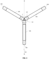
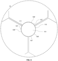
- the rollers belonging to the same set are positioned at an angle of 120° to each other.
- the two sets of rollers are preferably rotated 60° with respect to each other, so that in a front view of the rolling cassette the six rollers are at angles of 60° with respect to each other.
- the total length of the arc lengths of the arcs described by the grooves in the rollers in the first set is between 0.85 and 0.99% of the circumference of the supplied steel wire.
- the total length of the arc lengths of the arcs described by the rollers in the second set is between 0.9 and 0.99% of the circumference of the steel wire with predetermined diameter.
- the radius of the arc of a roller in the second set relates to the radius of the arc of a roller in the first set in a ratio between 0.5/1 and 0.7/1, preferably between 0.55/1 and 0.7/1, for example about 0.55/1; 0.56/1; 0.57/1; 0.58/1; 0.59/1; 0.60/1; 0.61/1; 0.62/1; 0.63/1; 0.64/1; 0.65/1; 0.66/1; 0.67/1; 0.68/1; 0.69/1; 0.70/1.
- the contact surface of the rollers in the first set and the contact surface of the rollers in the second set are between 7 and 9 cm apart on the steel wire.
- the rollers in the second set rotate between 1 and 50% faster, preferably between 2.5% and 35%, preferably between 5% and 20%, more preferably between 10 and 15%, for example about 10%, 11%, 12%, 13%, 14%, 15%, compared to the between 10 and 15%, compared to the rollers in the first set.
- the diameter of the steel wire is continuously measured after the second set of rollers and the rollers are adjusted based on the measured diameter.
- the method described herein can be used for cold or hot rolling of a steel wire.
- the method described herein is a method for cold rolling a steel wire.
- the rolling process is carried out at a temperature below the recrystallization temperature of the metal. More specifically, the rolling process can be carried out at room temperature.
- Cold rolling typically results in an increase in the tensile strength of the steel wire.
- the rolling results in an increase in the temperature of the steel wire to a temperature between 70 and 90°, preferably between 75 and 85°, more preferably about 80°.
- the method described herein further comprises in an embodiment the step of determining or measuring the cross-section or diameter of the drawn or rolled steel wire obtained in step (ii) as described above. Determining or measuring the diameter can be done immediately after rolling, or after any further processing steps such as slackening and/or driving the steel wire. Measuring the diameter can be done in different ways. In certain embodiments, the diameter is determined optically. This can be done by directing a set of one or more light sources (for example laser beams) in one or more directions perpendicular to the wire and detecting the transmitted light. An example of an arrangement based on this principle is described in patent EP0565090 . Such an arrangement allows the ovality and/or other shape parameters of the wire to be measured in addition to the diameter. Suitable setups for measuring the diameter of the rolled wire are commercially available, and available to a skilled person.
- Optical measuring devices are usually able to perform measurements (scans) at a high frequency.
- the diameter of the steel wire is measured at least 100, at least 250, at least 500, or at least 1000 times per second. This is particularly advantageous in a continuous process, where the steel wire is transported at a high speed.
- the distance between two consecutive measuring positions on the steel wire is at most 5 cm, more preferably at most 2 cm, even more preferably at most 1 cm, for example every 6 mm.
- the diameter can be determined in other ways, for example on the basis of the speed of the steel wire before and after rolling.
- the elongation of the wire can be deduced from the change in speed, and therefore also the corresponding reduction in diameter.
- one or more reference measurements of the wire diameter can be performed before rolling. This allows the diameter to be determined more precisely after rolling based on the speed measurements.
- the speed of the steel wire can be measured via contact or non-contact measurements, as known to a person skilled in the art. Suitable non-contact measuring techniques may include, for example, laser Doppler speed measurement.
- multiple reference measurements of the wire diameter can be performed. This allows the diameter to be determined more precisely.
- additional monitoring of the wire diameter can be done by means of a wire drawing system.
- the method described herein comprises controlling the sets of rollers in step (ii) on the basis of the determined diameter. Control can be done on one or two sets of rollers, preferably on the first set or the second set. In certain embodiments, the diameter of the rolled steel wire can be measured after each of the sets of rollers, with the sets being controlled individually based on the diameter measured after the respective roller.
- the control is typically based on the difference between a set value and the measured value, this difference is also called "error signal.” For example, when the measured diameter exceeds the set value, the set of rollers can be positioned closer together, reducing the gap between the rollers and thus the diameter of the wire. Conversely, if the measured diameter is lower than the set value, the gap between the rollers can be increased.
- the selected set value may depend on the minimum required wire diameter. Preferably, the minimum required wire diameter is used as the set value, with an additional margin. Since the method described here allows the spread on the wire diameter to be reduced, a relatively small margin is sufficient.
- a suitable margin is a maximum of 2%, preferably a maximum of 1%, and preferably a maximum of 0.5%.
- the variation in the diameter of the steel wire is reduced to a maximum of 1% and preferably a maximum of 0.5%.
- An alternative or addition to the measurement of the cross-section or diameter of the rolled wire obtained in step (ii) as described above is a measurement of the ovality of the steel wire. This can also be done using the optical method described above. A determination of the ovality can be important to check the quality of the rolled steel wire. During rolling, it is possible that the rollers press too hard on the wire, causing the wire to be deformed and the wire section to become smaller and a seam to form on the wire. The deformed steel wire then has a star-shaped cross-section, and the measured diameter is larger than the actual diameter. The determination of the ovality provides a determination of the quality of the rolled steel wire and can identify errors in the rolling process.
- Adjusting the position of the rollers is preferably done manually, alternatively the control can be done motorically, where the motors can be controlled by a regulator or controller, such as a PID controller.
- a PID controller (where PID stands for Proportional, Integral, Derivative) is a common controller and is well known to a person skilled in the art. However, it is not excluded that in other embodiments, a different controller can be used. Adjusting the position of the rollers can also be done pneumatically or hydraulically.
- the error signal is determined on the basis of a (moving) average of a certain number of measurements of the diameter. This is particularly advantageous when the measurement results show low precision. Due to the large differences between the measuring points, it makes more sense to base the control of the rollers on the average of a number of consecutive data points.
- the diameter of the rolled wire after step (ii) depends not only on the setting of the rollers, but also on the diameter of the steel wire provided in step (i). This diameter can also vary throughout the steel wire. Typically these variations are negligible compared to the change in diameter achieved by rolling. However, in extreme cases it is possible that the intrinsic variation in the steel wire as provided for in step (i) has a non-negligible share contribution to the variation in the diameter measured after rolling. This may mean that the control of the rollers based on the measured diameter is not optimal. It is therefore envisaged that in certain embodiments of the method the diameter of the steel wire is also determined before rolling, for example in step (i) or just before the first set of rollers in step (ii). This makes it possible to make a correction for the intrinsic variation of the diameter before rolling when controlling the rollers based on the measured diameter.
- the diameter of the steel wire before being drawn through the rolling cassette is a maximum of 0.5 mm larger than the predetermined diameter.
- a steel wire with a predetermined diameter of 5.5 mm, 7.5 mm and 4.7 mm will be a maximum of 6 mm, a maximum of 8 mm and a maximum of 5.2 mm at the entrance of the rolling cassette, respectively.
- the diameter of the steel wire after being drawn through the rolling cassette is a maximum of 0.06 mm larger or smaller than the predetermined diameter.
- a steel wire with a predetermined diameter of 5.5 mm, 7.5 mm and 4.7 mm will, after drawing, have a diameter of 5.44-5.56 mm, 7.44-7.56 mm and 4.64-4.76 mm, respectively.
- the ovality of the steel wire after being drawn through the rolling cassette is between -0.05 and 0.05 mm, preferably between -0.04 and 0.04 mm, more preferably between -0.03 and 0.03 mm, most preferably between -0.025 and 0.025 mm.
- the method described herein provides a drive for the steel wire.
- the steel wire is driven by a drive installation positioned after the rolling apparatus.
- the steel wire is pulled through the rolling apparatus in this way.
- the steel wire is preferably driven by means of one or more drawing blocks positioned along the production process and preferably after the rolling apparatus.
- the method described herein comprises coating the steel wire.
- the steel wire can be provided with a lubricant. This can be used to promote the rolling process and possible slackening. Suitable lubricants are well known to those skilled in the art.
- the wire is provided with a drawing soap such as sodium stearate or calcium stearate.
- the wire is provided with a lubricant as part of step (i), i.e. before rolling the steel wire.
- the lubricant can be applied in a continuous manner by spraying, dipping, brushing, or other techniques known to those skilled in the art.
- the steel wire is immersed in a bath with drawing soap, preferably drawing soap comprising sodium stearate.
- drawing soap preferably drawing soap comprising sodium stearate.
- the steel wire is pulled through the bath, whereby the drawing soap is applied to the steel wire.
- step i or prior to step ii the steel wire is drawn through a bath with drawing soap, whereby after drawing between 15 and 25 kg of steel wire through the bath, the bath is refreshed, with between 15 and 20 m% of the drawing soap being recovered.
- Refreshing the bath involves emptying and refilling the bath with fresh drawing soap, where the term "fresh drawing soap” refers to drawing soap that has not yet been used for the treatment of steel wire, i.e. as purchased.
- fresh drawing soap refers to drawing soap that has not yet been used for the treatment of steel wire, i.e. as purchased.
- after a passage of between 15 and 25 tons of steel wire between 80 and 85 m% of the drawing soap is removed from the bath and replaced with fresh drawing soap.
- the steel wire has a round cross-section after drawing.
- the steel wire obtained after step (ii) can cover a wide diameter range between 0.1 mm and 50 mm, preferably between 0.5 mm and 30 mm, more preferably between 2 mm and 16 mm, even more preferably between 4 and 8 mm, and most preferably a diameter selected from the list of: about 7.5 mm, about 5.5 mm, or about 4.7 mm.
- the wire strength is increased by drawing the steel wire to a wire strength between 500 and 1000 N/mm 2 , more preferably between 500 and 750 N/mm 2 .
- Steel wire such as hot-rolled steel wire
- the method described herein includes in step (iii) winding up, coiling up or rolling up the rolled steel wire onto a coil or into a bundle at the end of the process.
- the steel wire is rolled up on a coil.
- between 3 and 5.5 tons of steel wire are rolled up per coil, preferably between 3.5 and 5 tons, more preferably between 4 and 4.5 tons, even more preferably between 4.1 and 4.3 tons.
- the steel wire is rolled up on a coil with a diameter between 500 and 800 mm, more preferably between 550 and 750 mm, even more preferably between 600 and 700 mm, most preferably about 640 mm.
- the steel wire After the steel wire has been rolled up, it is cooled in the air in step (iii) (free convection). Preferably the wire is cooled for between 20 and 50 hours, more preferably between 30 and 50 hours, more preferably about 40 hours. Cooling is necessary because the steel wire also heats up due to the straightening operation during straightening in step (iv). The steel wire is therefore preferably cooled for at least 24 hours, so that the steel wire is sufficiently cooled everywhere on the coil or in the bundle. Preferably, cooling takes place until the steel wire is approximately room temperature.
- the steel wire is cooled for at least 40 hours. This is necessary to allow the material to cool and rest before the wire is straightened and cut. Forty hours of cooling provides sufficient cooling at both summer and winter temperatures
- the steel wire After cooling in step (iii), the steel wire is again unrolled and straightened in step (iv).
- the steel wire also heats up during straightening.
- the steel wire heats up during straightening to a temperature between 55 and 65°C, more preferably between 56 and 64°C, even more preferably between 57 and 63°C, most preferably between 58 and 62°C.
- straightening continues at a throughput speed between 20 and 150 m/min, preferably between 30 and 140 m/min, more preferably between 40 and 130 m/min, even more preferably between 50 and 120 m/min, even more preferably between 60 and 110 m/min, most preferably between 70 and 100 m/min.
- Straightening is done using drive rollers, where the pressure on the drive rollers is preferably between 1 and 10 bar, more preferably between 1 and 9 bar, even more preferably between 1 and 8 bar, even more preferably between 1 and 7 bar, even more preferably between 1 and 6 bar, even more preferably between 1 and 5 bar, most preferably between 1 and 4 bar.
- the steel wire is cut into bars in step (v).
- the straightening (step (iv)) and the cutting (step (v)) occur simultaneously.
- the bars obtained via the method described herein are specific for use in fence panels.
- the bars have a length between 600 and 3000 mm, preferably selected from the list of: 606, 608, 630, 806, 808, 830, 1006, 1008, 1030, 1206, 1208, 1230, 1406, 1408, 1430, 1606, 1608, 1630, 1806, 1808, 1830, 2006, 2008, 2030, 2206, 2208, 2230, 2406, 2408, 2430, 2508 or 2510 mm.
- the bars are smooth bars.
- the steel wire After the steel wire has been straightened and cut into bars, it is cooled in the air (free convection). Preferably the bars are cooled for between 10 and 40 hours, more preferably between 20 and 30 hours, more preferably about 24 hours.
- the bars can then be welded into a fence panel, preferably a twin-wire or double-wire fence panel.
- a fence panel preferably a twin-wire or double-wire fence panel.
- parallel vertical bars are welded to horizontal bars, with the vertical bars being welded at the same height between two horizontal bars.
- the invention concerns an apparatus for drawing, straightening and cutting steel wire into bars, suitable for use in fence panels.
- the apparatus according to the second aspect is suitable for carrying out a method according to the first aspect of the invention.
- the straightening apparatus and the cutting apparatus are part of a simultaneous straightening and cutting apparatus, positioned downstream of the drawing apparatus, suitable for simultaneously straightening and cutting the steel wire into bars.
- the invention concerns a smooth bar suitable for use in a fence panel.
- the invention concerns a smooth bar in which the variation in the diameter of the bar is a maximum of 1%.
- the smooth bar according to the third aspect is obtained through the use of an apparatus according to the second aspect or a method according to the first aspect.
- the bar has a wire strength between 500 and 1000 N/mm 2 , more preferably between 500 and 750 N/mm 2 .
- the apparatus also comprises at least one of the following: an unrolling apparatus for unrolling steel wire, positioned upstream of the rolling apparatus; an unrolling apparatus for unrolling steel wire, positioned upstream of the rolling apparatus; a drawing block for driving the steel wire; - at least one measuring apparatus for measuring the diameter of the steel wire and/or the rolled steel wire; and - a control of the set of rollers from the measuring apparatus.
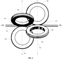
- the steel wire (101) is supplied according to the indicated transport direction (102).
- a second set of rollers (104) is located downstream of a first set of rollers (103).
- Each set consists of three rollers (105) provided with a groove (106), whereby the rollers (105) belonging to the same set (103, 104) are positioned at an angle of 120° to each other.
- the groove forms the contact surface (107) that makes contact with the steel wire, wherein the cross-section of the groove (106) describes an arc (108), and wherein the arc (108) is characterized by a radius, a central angle and an arc length.
- There is a gap (111) between the rollers of the same set so that the rollers do not damage each other.
- Table 1 shows the characteristics of the rollers for three different supplied steel wires (Examples 1-3).
- TABLE 1 Supply diameter Intended diameter Arc length 1 st set Arc length 2 nd set Gap 1 st set Gap 2 nd set
- Example 1 8.3 mm 7.5 mm 7.72 mm 7.46 mm 0.68 mm 0.36 mm
- Example 2 6.3 mm 5.5 mm 5.86 mm 5.43 mm 0.51 mm 0.33 mm
- Example 3 5.5 mm 4.7 mm 5.31 mm 4.52 mm 0.12 mm 0.39 mm
- Table 2 shows the reduction in diameter during the drawing of the steel wire for three different supplied steel wires (Examples 4-6). TABLE 2 Supply diameter Intended diameter Maximum diameter at the entrance of the rolling cassette Obtained diameter
- Example 4 8.3 mm 7.5 mm 8.0 mm 7.44 - 7.56 mm
- Example 5 6.3 mm 5.5 mm 6.0 mm 5.44 - 5.56 mm
- Example 6 5.5 mm 4.7 mm 5.2 mm 4.64 - 4.76 mm
Landscapes
- Engineering & Computer Science (AREA)
- Mechanical Engineering (AREA)
- Wire Processing (AREA)
- Metal Extraction Processes (AREA)
- Metal Rolling (AREA)
Abstract
The present invention concerns a method for drawing, straightening and cutting steel wire into bars suitable for use in fence panels, comprising the sequential steps of: (i) providing a steel wire; (ii) drawing the steel wire through a rolling cassette until a predetermined diameter is reached, the rolling cassette comprising two successive sets of three rollers, such that a second set of rollers is positioned downstream of a first set of rollers; (iii) the rolling up and cooling of the steel wire; (iv) unrolling and straightening the steel wire; and (v) cutting the steel wire into bars; where the steps i. to v. continue continuously.
Description
- The invention relates to a method for drawing, straightening and cutting steel wire into bars. More specifically, bars suitable for use in fence panels.
- Steel wire is an important raw material in industry and construction. However, to be useful, the wires must meet certain properties. For example, the wires must be sufficiently deformable and able to withstand high tensile stress.
- To obtain steel wires with both correct properties, the wires typically undergo various processing steps, such as rolling.
- Rolling a steel wire can be used to change the cross-section of the wire and/or to apply a profile to the wire surface. This also allows the mechanical properties of the wire to be changed.
- Typically, the wire diameter and therefore the weight of the metal wire is not uniform over the entire length of the wire. Due to the spread of the wire weight, there is a risk that the wire does not have the minimum weight in certain places. This is typically accommodated by producing the wires with a significant margin above the required minimum value. However, providing a margin results in a loss because a shorter wire is obtained for the same weight of metal. It is therefore important to keep the margin as small as possible and to limit the variation in the diameter of the metal wire.
- Methods, such as BE1021090, are aimed at rolling steel wire for use in concrete reinforcement. The specifications required for the steel wire obtained are therefore very different from those required for steel wire and bars for use in fence panels.
- Known methods are also disadvantageous because the wear of the rollers and the roller profile on the rollers is high. Rollers often need to be replaced because the lifespan (i.e., the time it can be in operation) of a roller is low. Known rollers need to be replaced after just a few months. If the rollers are not replaced in time, the diameter of the drawn wire will show too many variations. Moreover, replacing a roller takes a lot of time, which means that production can sometimes be halted for a week.
- There is therefore a need for an improved method for drawing, straightening and cutting steel wires into bars suitable for fence panels.
- The invention concerns a method for drawing, straightening and cutting steel wire into bars according to
claim 1. Preferred forms of the method are set out in claims 2-12. - In a second aspect, the invention concerns an apparatus for drawing, straightening and cutting steel wire into bars according to claim 13.
- In a third aspect, the invention concerns a bar according to claim 14.
- The invention is advantageous because the method is specifically adapted to producing bars for fence panels from steel wire. The specific roller profile (grooves in the rollers) ensures that there is hardly any material loss when reducing the diameter of the steel wire. This is because the variation in the diameter of the steel wire is reduced. In addition, the wire strength of the steel wire is increased for the specific application in fence panels. The roller profile has the great advantage that there is less dependence on fluctuations of the incoming raw steel wire and that the rollers can be adjusted more easily and therefore faster in the rolling cassette. This has also resulted in a significantly longer lifespan of the rollers.
- It is an objective of the invention to minimize the wear of the rollers, so that the lifespan of the rollers is maximized. It is also the aim of the invention to optimize the production of bars by reducing or even avoiding production downtime due to roller replacement.
- The purpose of the invention is to optimize the drawing, straightening and cutting process of steel wire.
- The invention concerns a method for drawing, straightening and cutting steel wire into bars suitable for use in a fence panel.
- Unless otherwise defined, all terms used in the description of the invention, including technical and scientific terms, have the meaning as commonly understood by a person skilled in the art to which the invention pertains. For a better understanding of the description of the invention, the following terms are explained explicitly.
- In this document, "a" and "the" refer to both the singular and the plural, unless the context presupposes otherwise. For example, "a segment" means one or more segments.
- When the term "around" or "about" is used in this document with a measurable quantity, a parameter, a duration or moment, and the like, then variations are meant of approx. 20% or less, preferably approx. 10% or less, more preferably approx. 5% or less, even more preferably approx. 1% or less, and even more preferably approx. 0.1% or less than and of the quoted value, insofar as such variations are applicable in the described invention. However, it must be understood that the value of a quantity used where the term "about" or "around" is used, is itself specifically disclosed.
- The terms "comprise," "comprising," "provided with," "contain," "containing," "include," "including" are synonyms and are inclusive or open-ended terms that indicate the presence of what follows, and which do not exclude or prevent the presence of other components, characteristics, elements, members, steps, as known from or disclosed in the prior art.
- The terms "consist of," "consisting of," "being composed of," "composed of," are synonyms and are exclusive or closed-ended terms indicating the presence of what follows, and excluding or precluding the presence of other components, features, elements, members, steps known or described in the art.
- Quoting numeric intervals by the endpoints includes all integers, fractions, and/or real numbers between the endpoints, including those endpoints.
- In a first aspect, the invention concerns a method for drawing, straightening and cutting steel wire into bars suitable for use in fence panels.
- In an embodiment, the method comprises the sequential steps of:
- i. providing a steel wire;
- ii. drawing the steel wire through a rolling cassette until a predetermined diameter is reached, the rolling cassette comprising two successive sets of three rollers, such that a second set of rollers is positioned downstream of a first set of rollers;
- iii. the rolling up and cooling of the steel wire;
- iv. unrolling and straightening the steel wire; and
- v. cutting the steel wire into bars;
- In a preferred embodiment, the rollers are provided with a contact surface that makes contact with the steel wire, wherein the contact surface is provided with a groove, wherein the cross-section of the groove describes an arc, and wherein the arc is characterized by a radius, a central angle and an arc length.
- In a preferred embodiment, the rollers are provided with a contact surface that makes contact with the steel wire, wherein the contact surface is provided with a groove, wherein the cross-section of the groove describes an arc, and wherein the arc is characterized by a radius, a central angle and an arc length, where the radius of the arc of a roller in the second set relates to the radius of the arc of a roller in the first set according to a ratio between 0.5/1 and 0.7/1.
- The roller profile has the great advantage that there is less dependence on fluctuations of the incoming raw steel wire and that the rollers can be adjusted more easily and therefore faster in the rolling cassette. This has also resulted in a significantly longer lifespan of the rollers.
- The method described herein is particularly suitable for rolling a steel wire in a continuous manner. Herein, the steel wire is transported along a predetermined route in a continuous manner, preferably at a speed in the range of about 10 m/min to about 1000 m/min, more preferably at a speed in the range of about 50 m/min to about 800 m/min, and most preferably at a speed in a range of about 100 m/min to about 700 m/min. For example, the transport speed of the steel wire can be about 100 m/min, about 125 m/min, about 150 m/min, about 175 m/min, about 200 m/min, about 250 m/min, about 300 m/min, about 350 m/min, about 400 m/min, about 450 m/min, about 500 m/min, about 550 m/min, about 600 m/min, about 650 m/min, or about 700 m/min. Most preferably, the transport speed is between 300 and 400 m/min. Since the current method reduces the diameter of the steel wire, there is a difference between the speed of the steel wire before drawing and the speed of the steel wire after drawing. The difference in speed corresponds to the degree of reduction in the diameter of the wire. For example, an incoming speed of 300 m/min with a reduction in the diameter of the wire between 5% and 20% will result in a respective outgoing speed of 315 m/min and 360 m/min. An incoming speed of 400 m/min and a lengthening of the steel wire between 5% and 20% result in a respective outgoing speed of 420 m/min and 480 m/min.
- In a preferred form, the steel wire is continuously transported to the first set of rollers at a speed between 330 m/min and 390 m/min, preferably about 360 m/min.
- In a continuous process, the transport speed of the steel wire remains substantially constant during drawing. The skilled person will understand that as a result of lengthening the wire, the speed at which the steel wire is transported expressed in unit weight per unit time typically remains constant, while the speed expressed in unit length per unit time can vary between the different steps of the process.
- In a first step (i) of the method according to the present invention, a steel wire is provided. The steel wire can be provided on a coil. In certain embodiments, step (i) thus comprises unrolling a steel wire from a coil.
- In certain embodiments, the steel wire provided in step (i) is a hot-rolled steel wire. Such steel wires are often used as a basic product for further processing. However, it is possible that the steel wire provided in step (i) is a cold-rolled coil.
- The steel wire provided in step (i) can have a smooth or profiled surface. Examples of wires with a profiled surface are ribbed, dented, and slightly dented wires. Such types of wires are well known to those skilled in the art. Preferably, the steel wire provided in step (i) is a smooth steel wire, optionally provided with irregularities on the surface.
- The steel wire provided can have any cross-section such as round, square, rectangular, oval or semi-oval cross-sections. The steel wires according to the present invention can be chosen within a wide diameter range lying between 0.1 mm and 50 mm, preferably between 0.5 mm and 30 mm, more preferably between 2 mm and 16 mm, even more preferably between 5 and 9 mm, and most preferably a diameter selected from the list of: about 8.5 mm, about 6.3 mm, or about 5.5 mm.
- For steel wires with a non-circular cross-section and/or a profiled surface, the term "diameter" as used herein denotes an equivalent diameter, specifically the nominal diameter of the wire. The term "nominal diameter" refers to the diameter of an imaginary wire with a circular cross-section of the same length and volume as the actual wire.
- The steel wire is made of unalloyed steel, low-alloy steel or high-alloy steel. Steel wire can be made from high or low carbon steel.
- Unalloyed steel contains a maximum of 1.5% of alloying elements (excluding carbon (C)). Unalloyed steel has a carbon percentage of 0.5% to 2%. Low-alloy steel contains between 1.5 and 5% alloying elements (excluding carbon). High-alloy steel contains more than 5% of alloying elements. The steel wire is preferably made from unalloyed steel. The term "alloying elements" refers to the elements that are present in the alloy in addition to iron and carbon. In a preferred form, the steel wire is made of an alloy comprising iron (Fe), carbon (C) and alloying elements. Preferably, the alloy comprises a maximum of 1.5% alloying elements, more preferably a maximum of 1.4%, even more preferably a maximum of 1.3%, even more preferably a maximum of 1.2%, most preferably a maximum of 1.1%. Preferably the alloy comprises at least 0.5% alloying elements, more preferably at least 0.6%, even more preferably at least 0.7%, even more preferably at least 0.8%, even more preferably at least 0.9%, most preferably at least 1%. In another preferred embodiment, the alloy comprises between 0.5 and 1.5% alloying elements, preferably between 0.6 and 1.5%, more preferably between 0.7 and 1.4%, even more preferably between 0.8 and 1.3%, even more preferably between 0.9 and 1.2%, most preferably between 1 and 1.1%.
- In an embodiment, the alloy comprises a maximum of 0.1% C, more preferably a maximum of 0.09%, even more preferably a maximum of 0.085%, even more preferably a maximum of 0.08%, most preferably a maximum of 0.075%. Preferably, the alloy comprises at least 0.025% C, more preferably at least 0.03%, even more preferably at least 0.035%, even more preferably at least 0.04%, most preferably at least 0.045%. In another preferred embodiment, the alloy comprises between 0.02 and 0.1% C, preferably between 0.025 and 0.09%, more preferably between 0.035 and 0.085%, even more preferably between 0.04 and 0.08%, most preferably between 0.045 and 0.075%.
- In a preferred embodiment, the alloy comprises alloying elements selected from the list of: manganese (Mn), silicon (Si), sulfur (S), phosphorus (P), nitrogen (N), copper (Cu), chromium (Cr), nickel (Ni), niobium (Nb), tin (Sn), aluminum (Al) or any combination thereof. Preferably the alloy comprises manganese (Mn), silicon (Si), sulfur (S), phosphorus (P), nitrogen (N), copper (Cu), and optionally chromium (Cr), nickel (Ni), niobium (Nb), tin (Sn), aluminum (Al).
- Preferably, the alloy comprises Mn in an amount between 0.3 and 0.5%, more preferably between 0.35 and 0.45%, Si in an amount between 0.05 and 0.25%, more preferably between 0.1 and 0.2%, S in an amount between 0.01 and 0.045%, more preferably between 0.015 and 0.04%, P in an amount between 0.005 and 0.03%, more preferably between 0.005 and 0.025%, Cu in an amount between 0.2 and 0.4%, more preferably between 0.25 and 0.35%, N in an amount between 0.005 and 0.02%, more preferably between 0.005 and 0.015%, and Cr in an amount of up to 0.15%, more preferably up to 0.1%, Ni in an amount up to 0.15%, more preferably up to 0.1%, and Nb in an amount up to 0.005%, more preferably up to 0.002%, Sn in an amount up to 0.05%, more preferably up to 0.03%, and/or Al in an amount up to 0.005%, more preferably up to 0.003%.
- The method described herein comprises in a step (ii) drawing the steel wire. This produces a rolled steel wire, which can be further processed (see below). Drawing processes for steel wires are well known to those skilled in the art. Here the wire is guided through a set of typically two, four or six rolls or rollers, reducing the diameter of the wire. Rolling is a shaping technique in which a metal wire is deformed by two or more rolls or rollers. Rolling a steel wire can be used to change the cross-section of the wire. Cold rolling is performed at a temperature below the recrystallization temperature, for example at room temperature, and typically increases the wire strength.
- During drawing, the steel wire is pulled through a rolling cassette where a predetermined diameter is reached. The rolling cassette comprises two successive sets of three rollers, so that a second set of rollers is positioned downstream of a first set of rollers.
- In a preferred embodiment, the rollers are provided with a contact surface that makes contact with the steel wire, wherein the contact surface is provided with a groove, wherein the cross-section of the groove describes an arc, and wherein the arc is characterized by a radius, a central angle and an arc length.
- The groove has a width that corresponds to a rectilinear distance between the end points of the arc. Preferably, the width of the groove of a roller in the first set is between 1 and 10 mm, more preferably between 2 and 9 mm, even more preferably between 3 and 8 mm, preferably between 4.5 and 7.5 mm.
- Preferably, the width of the groove of a roller in the second set is between 1 and 10 mm, more preferably between 2 and 8 mm, even more preferably between 3 and 7 mm, preferably between 3.5 and 6.5 mm.
- In a preferred form, the width of the groove of a roller in the second set relates to the width of the groove of a roller in the first set in a ratio between 0.5/1 and 1/1, preferably between 0. 75/1 and 0.9/1, for example about 0.75/1; 0.76/1; 0.77/1; 0.78/1; 0.79/1; 0.80/1; 0.81/1; 0.82/1; 0.83/1; 0.84/1; 0.85/1; 0.86/1; 0.87/1; 0.88/1; 0.89/1; 0.90/1.
- In a preferred form, the radius of the arc of a roller in the first set is related to the width of the groove of a roller in the first set in a ratio between 0.5/1 and 1/1, preferably between 0.75/1 and 0.9/1, for example about 0.75/1; 0.76/1; 0.77/1; 0.78/1; 0.79/1; 0.80/1; 0.81/1; 0.82/1; 0.83/1; 0.84/1; 0.85/1; 0.86/1; 0.87/1; 0.88/1; 0.89/1; 0.90/1.
- In a preferred form, the radius of the arc of a roller in the second set is related to the width of the groove of a roller in the second set in a ratio between 0.5/1 and 1/1, preferably between 0.55/1 and 0.65/1, for example about 0.55/1; 0.56/1; 0.57/1; 0.58/1; 0.59/1; 0.60/1; 0.61/1; 0.62/1; 0.63/1; 0.64/1; 0.65/1.
- With these ratios, the rollers proved to be easy to adjust and resulted in a consistent result, even with fluctuating incoming wire rod. In addition, no edges or lines were noticeable on the steel wires when using this setting.
- The term "central angle" refers to the angle between the two lines that run from the ends of the arc to the center of the associated circle.
- The rollers are typically cylindrical or annular, with the jacket forming the contact surface with the steel wire to be rolled and where the jacket is provided with a groove and/or profile. The invention preferably concerns annular rollers provided with a groove in the jacket. The rollers are positioned relative to each other so that their grooves together form a gap that is smaller than the diameter of the supplied steel wire, so that the steel wire is deformed as the wire passes through the roller.
- Step (ii) of the method described herein therefore involves rolling the steel wire using two sets of rollers in series, the rolling cassette comprising two successive sets of three rollers, such that a second set of rollers is positioned downstream of a first set of rollers. The total deformation of the steel wire by rolling with two sets of rollers usually reduces the diameter of the wire between 1 and 50%, preferably between 2.5% and 35%, preferably between 5% and 20%, more preferably between 10 and 15%, for example about 10%, 11%, 12%, 13%, 14%, 15%, with respect to the wire provided in step (i).
- In a preferred form, the rollers belonging to the same set are positioned at an angle of 120° to each other. The two sets of rollers are preferably rotated 60° with respect to each other, so that in a front view of the rolling cassette the six rollers are at angles of 60° with respect to each other.
- In a preferred form, the total length of the arc lengths of the arcs described by the grooves in the rollers in the first set is between 0.85 and 0.99% of the circumference of the supplied steel wire.
- In a preferred form, the total length of the arc lengths of the arcs described by the rollers in the second set is between 0.9 and 0.99% of the circumference of the steel wire with predetermined diameter.
- In a preferred form, the radius of the arc of a roller in the second set relates to the radius of the arc of a roller in the first set in a ratio between 0.5/1 and 0.7/1, preferably between 0.55/1 and 0.7/1, for example about 0.55/1; 0.56/1; 0.57/1; 0.58/1; 0.59/1; 0.60/1; 0.61/1; 0.62/1; 0.63/1; 0.64/1; 0.65/1; 0.66/1; 0.67/1; 0.68/1; 0.69/1; 0.70/1.
- In a preferred form, the contact surface of the rollers in the first set and the contact surface of the rollers in the second set are between 7 and 9 cm apart on the steel wire.
- In a preferred form, the rollers in the second set rotate between 1 and 50% faster, preferably between 2.5% and 35%, preferably between 5% and 20%, more preferably between 10 and 15%, for example about 10%, 11%, 12%, 13%, 14%, 15%, compared to the between 10 and 15%, compared to the rollers in the first set.
- In a preferred form, the diameter of the steel wire is continuously measured after the second set of rollers and the rollers are adjusted based on the measured diameter.
- The method described herein can be used for cold or hot rolling of a steel wire. In a preferred form, the method described herein is a method for cold rolling a steel wire.
- The rolling process is carried out at a temperature below the recrystallization temperature of the metal. More specifically, the rolling process can be carried out at room temperature. Cold rolling typically results in an increase in the tensile strength of the steel wire. The rolling results in an increase in the temperature of the steel wire to a temperature between 70 and 90°, preferably between 75 and 85°, more preferably about 80°.
- The method described herein further comprises in an embodiment the step of determining or measuring the cross-section or diameter of the drawn or rolled steel wire obtained in step (ii) as described above. Determining or measuring the diameter can be done immediately after rolling, or after any further processing steps such as slackening and/or driving the steel wire. Measuring the diameter can be done in different ways. In certain embodiments, the diameter is determined optically. This can be done by directing a set of one or more light sources (for example laser beams) in one or more directions perpendicular to the wire and detecting the transmitted light. An example of an arrangement based on this principle is described in patent
EP0565090 . Such an arrangement allows the ovality and/or other shape parameters of the wire to be measured in addition to the diameter. Suitable setups for measuring the diameter of the rolled wire are commercially available, and available to a skilled person. - Optical measuring devices are usually able to perform measurements (scans) at a high frequency. In certain embodiments, the diameter of the steel wire is measured at least 100, at least 250, at least 500, or at least 1000 times per second. This is particularly advantageous in a continuous process, where the steel wire is transported at a high speed. In certain embodiments, the distance between two consecutive measuring positions on the steel wire is at most 5 cm, more preferably at most 2 cm, even more preferably at most 1 cm, for example every 6 mm.
- In certain embodiments, the diameter can be determined in other ways, for example on the basis of the speed of the steel wire before and after rolling. The elongation of the wire can be deduced from the change in speed, and therefore also the corresponding reduction in diameter. Optionally, one or more reference measurements of the wire diameter can be performed before rolling. This allows the diameter to be determined more precisely after rolling based on the speed measurements. The speed of the steel wire can be measured via contact or non-contact measurements, as known to a person skilled in the art. Suitable non-contact measuring techniques may include, for example, laser Doppler speed measurement. Optionally, multiple reference measurements of the wire diameter can be performed. This allows the diameter to be determined more precisely. In certain embodiments, additional monitoring of the wire diameter can be done by means of a wire drawing system.
- In a further step, the method described herein comprises controlling the sets of rollers in step (ii) on the basis of the determined diameter. Control can be done on one or two sets of rollers, preferably on the first set or the second set. In certain embodiments, the diameter of the rolled steel wire can be measured after each of the sets of rollers, with the sets being controlled individually based on the diameter measured after the respective roller.
- The control is typically based on the difference between a set value and the measured value, this difference is also called "error signal." For example, when the measured diameter exceeds the set value, the set of rollers can be positioned closer together, reducing the gap between the rollers and thus the diameter of the wire. Conversely, if the measured diameter is lower than the set value, the gap between the rollers can be increased. The selected set value may depend on the minimum required wire diameter. Preferably, the minimum required wire diameter is used as the set value, with an additional margin. Since the method described here allows the spread on the wire diameter to be reduced, a relatively small margin is sufficient. A suitable margin is a maximum of 2%, preferably a maximum of 1%, and preferably a maximum of 0.5%. Preferably, during rolling in step (ii), the variation in the diameter of the steel wire is reduced to a maximum of 1% and preferably a maximum of 0.5%.
- An alternative or addition to the measurement of the cross-section or diameter of the rolled wire obtained in step (ii) as described above is a measurement of the ovality of the steel wire. This can also be done using the optical method described above. A determination of the ovality can be important to check the quality of the rolled steel wire. During rolling, it is possible that the rollers press too hard on the wire, causing the wire to be deformed and the wire section to become smaller and a seam to form on the wire. The deformed steel wire then has a star-shaped cross-section, and the measured diameter is larger than the actual diameter. The determination of the ovality provides a determination of the quality of the rolled steel wire and can identify errors in the rolling process. Adjusting the position of the rollers is preferably done manually, alternatively the control can be done motorically, where the motors can be controlled by a regulator or controller, such as a PID controller. A PID controller (where PID stands for Proportional, Integral, Derivative) is a common controller and is well known to a person skilled in the art. However, it is not excluded that in other embodiments, a different controller can be used. Adjusting the position of the rollers can also be done pneumatically or hydraulically.
- In certain embodiments, the error signal is determined on the basis of a (moving) average of a certain number of measurements of the diameter. This is particularly advantageous when the measurement results show low precision. Due to the large differences between the measuring points, it makes more sense to base the control of the rollers on the average of a number of consecutive data points.
- The diameter of the rolled wire after step (ii) depends not only on the setting of the rollers, but also on the diameter of the steel wire provided in step (i). This diameter can also vary throughout the steel wire. Typically these variations are negligible compared to the change in diameter achieved by rolling. However, in extreme cases it is possible that the intrinsic variation in the steel wire as provided for in step (i) has a non-negligible share contribution to the variation in the diameter measured after rolling. This may mean that the control of the rollers based on the measured diameter is not optimal. It is therefore envisaged that in certain embodiments of the method the diameter of the steel wire is also determined before rolling, for example in step (i) or just before the first set of rollers in step (ii). This makes it possible to make a correction for the intrinsic variation of the diameter before rolling when controlling the rollers based on the measured diameter.
- In a preferred embodiment of the invention, the diameter of the steel wire before being drawn through the rolling cassette is a maximum of 0.5 mm larger than the predetermined diameter. For example, a steel wire with a predetermined diameter of 5.5 mm, 7.5 mm and 4.7 mm will be a maximum of 6 mm, a maximum of 8 mm and a maximum of 5.2 mm at the entrance of the rolling cassette, respectively.
- In a preferred form of the invention, the diameter of the steel wire after being drawn through the rolling cassette is a maximum of 0.06 mm larger or smaller than the predetermined diameter. For example, a steel wire with a predetermined diameter of 5.5 mm, 7.5 mm and 4.7 mm will, after drawing, have a diameter of 5.44-5.56 mm, 7.44-7.56 mm and 4.64-4.76 mm, respectively.
- In a preferred form of the invention, the diameter of the steel wire after being drawn through the rolling cassette is a maximum of 0.06 mm larger or smaller than the predetermined diameter. For example, a steel wire with a predetermined diameter of 5.5 mm, 7.5 mm and 4.7 mm will, after drawing, have a diameter of 5.44-5.56 mm, 7.44-7.56 mm and 4.64-4.76 mm, respectively.
- In a preferred form of the invention, the ovality of the steel wire after being drawn through the rolling cassette is between -0.05 and 0.05 mm, preferably between -0.04 and 0.04 mm, more preferably between -0.03 and 0.03 mm, most preferably between -0.025 and 0.025 mm.
- In order to control the steel wire through the sets of rollers, in certain embodiments the method described herein provides a drive for the steel wire. Preferably, the steel wire is driven by a drive installation positioned after the rolling apparatus. The steel wire is pulled through the rolling apparatus in this way. The steel wire is preferably driven by means of one or more drawing blocks positioned along the production process and preferably after the rolling apparatus.
- In an embodiment, the method described herein comprises coating the steel wire. More specifically, the steel wire can be provided with a lubricant. This can be used to promote the rolling process and possible slackening. Suitable lubricants are well known to those skilled in the art. In certain embodiments, the wire is provided with a drawing soap such as sodium stearate or calcium stearate. Preferably, the wire is provided with a lubricant as part of step (i), i.e. before rolling the steel wire. The lubricant can be applied in a continuous manner by spraying, dipping, brushing, or other techniques known to those skilled in the art.
- In a preferred form, the steel wire is immersed in a bath with drawing soap, preferably drawing soap comprising sodium stearate. In this form, the steel wire is pulled through the bath, whereby the drawing soap is applied to the steel wire.
- In an embodiment, in step i or prior to step ii, the steel wire is drawn through a bath with drawing soap, whereby after drawing between 15 and 25 kg of steel wire through the bath, the bath is refreshed, with between 15 and 20 m% of the drawing soap being recovered. Refreshing the bath involves emptying and refilling the bath with fresh drawing soap, where the term "fresh drawing soap" refers to drawing soap that has not yet been used for the treatment of steel wire, i.e. as purchased. In this embodiment, after a passage of between 15 and 25 tons of steel wire, between 80 and 85 m% of the drawing soap is removed from the bath and replaced with fresh drawing soap.
- It has been shown that partial recovery of the drawing soap (in this case 15 to 20 m%) significantly increases the drawing efficiency and straightening efficiency. The drawing soap facilitates deformation during drawing and straightening and also prevents excessive heat development. The drawing soap and the recovery of part of the drawing soap also contributes to minimal wear of the rollers in the rolling cassette.
- The steel wire has a round cross-section after drawing. According to the present invention, the steel wire obtained after step (ii) can cover a wide diameter range between 0.1 mm and 50 mm, preferably between 0.5 mm and 30 mm, more preferably between 2 mm and 16 mm, even more preferably between 4 and 8 mm, and most preferably a diameter selected from the list of: about 7.5 mm, about 5.5 mm, or about 4.7 mm.
- In a preferred form, the wire strength is increased by drawing the steel wire to a wire strength between 500 and 1000 N/mm2, more preferably between 500 and 750 N/mm2.
- Steel wire, such as hot-rolled steel wire, is typically transported and stored on coils or in bundles. Similarly, the method described herein includes in step (iii) winding up, coiling up or rolling up the rolled steel wire onto a coil or into a bundle at the end of the process.
- In a preferred form, the steel wire is rolled up on a coil. In a further preferred form, between 3 and 5.5 tons of steel wire are rolled up per coil, preferably between 3.5 and 5 tons, more preferably between 4 and 4.5 tons, even more preferably between 4.1 and 4.3 tons.
- In a preferred form, the steel wire is rolled up on a coil with a diameter between 500 and 800 mm, more preferably between 550 and 750 mm, even more preferably between 600 and 700 mm, most preferably about 640 mm.
- After the steel wire has been rolled up, it is cooled in the air in step (iii) (free convection). Preferably the wire is cooled for between 20 and 50 hours, more preferably between 30 and 50 hours, more preferably about 40 hours. Cooling is necessary because the steel wire also heats up due to the straightening operation during straightening in step (iv). The steel wire is therefore preferably cooled for at least 24 hours, so that the steel wire is sufficiently cooled everywhere on the coil or in the bundle. Preferably, cooling takes place until the steel wire is approximately room temperature.
- In a preferred form, the steel wire is cooled for at least 40 hours. This is necessary to allow the material to cool and rest before the wire is straightened and cut. Forty hours of cooling provides sufficient cooling at both summer and winter temperatures
- After cooling in step (iii), the steel wire is again unrolled and straightened in step (iv). The steel wire also heats up during straightening. In a preferred form, the steel wire heats up during straightening to a temperature between 55 and 65°C, more preferably between 56 and 64°C, even more preferably between 57 and 63°C, most preferably between 58 and 62°C.
- In an embodiment, straightening continues at a throughput speed between 20 and 150 m/min, preferably between 30 and 140 m/min, more preferably between 40 and 130 m/min, even more preferably between 50 and 120 m/min, even more preferably between 60 and 110 m/min, most preferably between 70 and 100 m/min.
- Straightening is done using drive rollers, where the pressure on the drive rollers is preferably between 1 and 10 bar, more preferably between 1 and 9 bar, even more preferably between 1 and 8 bar, even more preferably between 1 and 7 bar, even more preferably between 1 and 6 bar, even more preferably between 1 and 5 bar, most preferably between 1 and 4 bar.
- The steel wire is cut into bars in step (v). In a preferred form, the straightening (step (iv)) and the cutting (step (v)) occur simultaneously. The bars obtained via the method described herein are specific for use in fence panels. In a preferred form, the bars have a length between 600 and 3000 mm, preferably selected from the list of: 606, 608, 630, 806, 808, 830, 1006, 1008, 1030, 1206, 1208, 1230, 1406, 1408, 1430, 1606, 1608, 1630, 1806, 1808, 1830, 2006, 2008, 2030, 2206, 2208, 2230, 2406, 2408, 2430, 2508 or 2510 mm. In a preferred form the bars are smooth bars.
- After the steel wire has been straightened and cut into bars, it is cooled in the air (free convection). Preferably the bars are cooled for between 10 and 40 hours, more preferably between 20 and 30 hours, more preferably about 24 hours.
- The bars can then be welded into a fence panel, preferably a twin-wire or double-wire fence panel. With double-wire fence panels, parallel vertical bars are welded to horizontal bars, with the vertical bars being welded at the same height between two horizontal bars.
- In a second aspect, the invention concerns an apparatus for drawing, straightening and cutting steel wire into bars, suitable for use in fence panels.
- In a preferred embodiment the apparatus comprises:
- a rolling apparatus,
- a drawing apparatus, positioned downstream of the rolling apparatus, suitable for driving the apparatus, wherein the rolling apparatus comprises a rolling cassette,
- a straightening apparatus, positioned downstream of the drawing apparatus, suitable for straightening the steel wire prior to cutting, and
- a cutting apparatus, positioned downstream of the straightening apparatus, suitable for cutting steel wire into bars,
- In a further embodiment, the apparatus according to the second aspect is suitable for carrying out a method according to the first aspect of the invention.
- In a preferred form, the straightening apparatus and the cutting apparatus are part of a simultaneous straightening and cutting apparatus, positioned downstream of the drawing apparatus, suitable for simultaneously straightening and cutting the steel wire into bars.
- In a third aspect, the invention concerns a smooth bar suitable for use in a fence panel. In a preferred embodiment, the invention concerns a smooth bar in which the variation in the diameter of the bar is a maximum of 1%.
- In a further embodiment, the smooth bar according to the third aspect is obtained through the use of an apparatus according to the second aspect or a method according to the first aspect.
- In a preferred form, the bar has a wire strength between 500 and 1000 N/mm2, more preferably between 500 and 750 N/mm2.
- In a particular embodiment, the apparatus also comprises at least one of the following: an unrolling apparatus for unrolling steel wire, positioned upstream of the rolling apparatus; an unrolling apparatus for unrolling steel wire, positioned upstream of the rolling apparatus; a drawing block for driving the steel wire; - at least one measuring apparatus for measuring the diameter of the steel wire and/or the rolled steel wire; and - a control of the set of rollers from the measuring apparatus.
- In what follows, the invention is described by way of non-limiting examples illustrating the invention, and which are not intended to and should not be interpreted as limiting the scope of the invention.
-
-
Figure 1 shows a schematic representation of a particular embodiment of the method described herein for drawing, straightening and cutting a steel wire into bars.
The method comprises in a first step the provision of a rolled up steel wire (1) and the continuous unrolling of the steel wire (2). The wire is transported through the various steps of the method at a speed of approximately 6 m/s. The steel wire is then drawn at room temperature (3) using two sets of 3 rollers. This reduces the diameter of the wire by approximately 10% to 15%. The gap between the rollers is controlled by a motor. In a next step, the diameter of the wire is measured optically (10). This is done at a frequency of approximately 1200 measurements per second, which equates to approximately one measurement every 6 mm. Based on the measured diameter, the set of rollers is controlled in step (11), so that a uniform wire thickness is obtained. Due to the drawing, the wire heats up to a temperature of approximately 80°C and therefore the drawn steel wire is coiled (4) on a coil or in a bundle and cooled (5) for 40 hours. The cooling is done indirectly in the air through free convection. In a further step, the steel wire is uncoiled again (6) and straightened (7). Simultaneously with the straightening (7), the steel wire is cut (8) to lengths of 606, 608, 630, 806, 808, 830, 1006, 1008, 1030, 1206, 1208, 1230, 1406, 1408, 1430, 1606, 1608, 1630, 1806, 1808, 1830, 2006, 2008, 2030, 2206, 2208, 2230, 2406, 2408, 2430, 2508 and 2510 mm, producing smooth bars suitable for use in fence panels. By straightening, the wire heats up to a temperature of approximately 60°C and therefore the bars are cooled (9) for 24 hours. The cooling is done indirectly in the air through free convection.
This method allows the spread on the wire diameter to be kept smaller compared to standard methods. This allows an additional reduction of 10 to 15% to be achieved, while guaranteeing the required minimum diameter of the wire. This therefore means a significant material gain. -
Figure 2 shows an embodiment of the rolling cassette described herein, comprising two sets of three rollers. The third roller of each set is hidden to make the figures more visible. -
Figure 3 shows a view of the first set of rollers against the supply direction of the steel wire (section BB inFigure 1 ). -
Figure 4 shows a view of the second set of rollers in the supply direction of the steel wire (section AA inFigure 1 ). -
Figure 5 shows an enlarged view of the first set of rollers against the supply direction of the steel wire (section C onFigure 3 ). -
Figure 6 shows an enlarged view of the second set of rollers in the supply direction of the steel wire (section D onFigure 4 ). - The following reference numbers refer to:
- 101 supplied steel wire
- 102 transport direction
- 103 first set of rollers
- 104 second set of rollers
- 105 roller
- 106 groove
- 107 contact surface
- 108 arc cross section of the groove of a roller from the first set
- 108' arc cross-section of the groove of a roller from the second set
- 109 equivalent diameter supplied steel wire
- 110 intended (predetermined diameter)
- 111 gap between rollers
- The steel wire (101) is supplied according to the indicated transport direction (102). A second set of rollers (104) is located downstream of a first set of rollers (103). Each set consists of three rollers (105) provided with a groove (106), whereby the rollers (105) belonging to the same set (103, 104) are positioned at an angle of 120° to each other. The groove forms the contact surface (107) that makes contact with the steel wire, wherein the cross-section of the groove (106) describes an arc (108), and wherein the arc (108) is characterized by a radius, a central angle and an arc length. There is a gap (111) between the rollers of the same set so that the rollers do not damage each other.
- Table 1 shows the characteristics of the rollers for three different supplied steel wires (Examples 1-3).
TABLE 1 Supply diameter Intended diameter Arc length 1st set Arc length 2nd set Gap 1st set Gap 2nd set Example 1 8.3 mm 7.5 mm 7.72 mm 7.46 mm 0.68 mm 0.36 mm Example 2 6.3 mm 5.5 mm 5.86 mm 5.43 mm 0.51 mm 0.33 mm Example 3 5.5 mm 4.7 mm 5.31 mm 4.52 mm 0.12 mm 0.39 mm - Table 2 shows the reduction in diameter during the drawing of the steel wire for three different supplied steel wires (Examples 4-6).
TABLE 2 Supply diameter Intended diameter Maximum diameter at the entrance of the rolling cassette Obtained diameter Example 4 8.3 mm 7.5 mm 8.0 mm 7.44 - 7.56 mm Example 5 6.3 mm 5.5 mm 6.0 mm 5.44 - 5.56 mm Example 6 5.5 mm 4.7 mm 5.2 mm 4.64 - 4.76 mm
Claims (15)
- A method for drawing, straightening and cutting steel wire into bars suitable for use in fence panels, comprising the steps of:i. providing a steel wire;ii. drawing the steel wire through a rolling cassette until a predetermined diameter is reached, the rolling cassette comprising two successive sets of three rollers, such that a second set of rollers is positioned downstream of a first set of rollers;iii. the rolling up and cooling of the steel wire;iv. unrolling and straightening the steel wire; andv. cutting the steel wire into bars;where the steps i. to v. take place continuously, and wherein the rollers are provided with a contact surface that makes contact with the steel wire, wherein the contact surface is provided with a groove, wherein the cross-section of the groove describes an arc, and wherein the arc is characterized by a radius, a central angle and an arc length, wherein the radius of the arc of a roller in the second set relates to the radius of the arc of a roller in the first set according to a ratio between 0.5/1 and 0.7/1.
- Method according to claim 1, wherein, in step i or prior to step ii, the steel wire is drawn through a bath with drawing soap, whereby after drawing between 15 and 25 ton of steel wire through the bath, the bath is refreshed, with between 15 and 20 m% of the drawing soap being recovered.
- Method according to claim 1 or 2, wherein the total length of the arc lengths of the arcs described by the rollers in the first set is between 0.85 and 0.99% of the circumference of the supplied steel wire.
- Method according to any one of the preceding claims, wherein the total length of the arc lengths of the arcs described by the rollers in the second set is between 0.9 and 0.99% of the circumference of the steel wire with predetermined diameter.
- Method according to any one of the preceding claims, wherein the contact surface of the rollers in the first set and the contact surface of the rollers in the second set are between 7 and 9 cm apart on the steel wire.
- Method according to any one of the preceding claims, wherein the diameter of the steel wire reduces by 10 to 15% during drawing.
- Method according to any one of the preceding claims, wherein the rollers in the second set rotate between 10 and 15% faster than the rollers in the first set.
- Method according to any one of the preceding claims, wherein the steel wire is continuously transported to the first set of rollers at a speed between 5.5 m/s and 6.5 m/s, preferably about 6 m/s.
- Method according to any one of the preceding claims, wherein the diameter of the steel wire is continuously measured after the second set of rollers and the rollers are adjusted on the basis of the measured diameter.
- Method according to any one of the preceding claims, wherein the diameter of the steel wire before being drawn through the rolling cassette is a maximum of 0.5 mm larger than the predetermined diameter.
- Method according to any one of the preceding claims, wherein the diameter of the steel wire after being drawn through the rolling cassette is a maximum of 0.06 mm larger or smaller than the predetermined diameter.
- Method according to any one of the preceding claims, wherein the groove has a width that corresponds to a rectilinear distance between the end points of the arc, and wherein the width of the groove of a roller in the second set is related to the width of the groove of a roller in the first set according to a ratio preferably between 0.75/1 and 0.9/1.
- Method according to any one of the preceding claims, wherein the groove has a width that corresponds to a rectilinear distance between the end points of the arc, and wherein the radius of the arc of a roller in the first set is related to the width of the groove of a roller in the first set according to a ratio between 0.75/1 and 0.9/1 and wherein the radius of the arc of a roller in the second set is related to the width of the groove of a roller in the second set according to a ratio between 0.55/1 and 0.65/1.
- Method according to claim 13, wherein the width of the groove of a roller in the first set is between 4.5 and 7.5 mm, and wherein the width of the groove of a roller in the second set is between 3.5 and 6.5 mm.
- An apparatus for drawing, straightening and cutting steel wire into bars, suitable for use in fence panels, comprising:- a rolling apparatus,- a drawing apparatus, positioned downstream of the rolling apparatus, suitable for driving the apparatus, wherein the rolling apparatus comprises a rolling cassette,- a straightening apparatus, positioned downstream of the drawing apparatus, suitable for straightening the steel wire prior to cutting, and- a cutting apparatus, positioned downstream of the straightening apparatus, suitable for cutting steel wire into bars,the rolling cassette comprising two successive sets of three rollers, so that a second set of rollers is positioned downstream of a first set of rollers, and wherein the rollers are provided with a contact surface suitable for making contact with a steel wire, wherein the contact surface is provided with a groove, wherein the cross-section of the groove describes an arc, and wherein the arc is characterized by a radius, a central angle and an arc length, wherein the radius of the arc of a roller in the second set relates to the radius of the arc of a roller in the first set according to a ratio between 0.5/1 and 0.7/1.
Applications Claiming Priority (1)
| Application Number | Priority Date | Filing Date | Title |
|---|---|---|---|
| BE20225652A BE1030793B1 (en) | 2022-08-22 | 2022-08-22 | METHOD FOR PULLING, STRAIGHTENING AND CUTTING STEEL WIRE INTO BARS |
Publications (1)
| Publication Number | Publication Date |
|---|---|
| EP4327955A1 true EP4327955A1 (en) | 2024-02-28 |
Family
ID=83115504
Family Applications (1)
| Application Number | Title | Priority Date | Filing Date |
|---|---|---|---|
| EP23192610.6A Pending EP4327955A1 (en) | 2022-08-22 | 2023-08-22 | Method for drawing, straightening and cutting steel wire into bars |
Country Status (2)
| Country | Link |
|---|---|
| EP (1) | EP4327955A1 (en) |
| BE (1) | BE1030793B1 (en) |
Citations (9)
| Publication number | Priority date | Publication date | Assignee | Title |
|---|---|---|---|---|
| US3552164A (en) * | 1967-03-29 | 1971-01-05 | Ilario Properzi | Rolling mill |
| US3981752A (en) * | 1973-11-15 | 1976-09-21 | Bethlehem Steel Corporation | Method for controlling the temperature of steel during hot-rolling on a continuous hot-rolling mill |
| US4141071A (en) * | 1977-03-17 | 1979-02-20 | Bethlehem Steel Corporation | Automatic diametric dimension control for mill for rolling round bars |
| JPS61159217A (en) * | 1984-12-29 | 1986-07-18 | Asahi Chem Ind Co Ltd | High speed wire drawing equipment of wire rod |
| JPH04200803A (en) * | 1990-11-29 | 1992-07-21 | Nippon Steel Corp | Three-rolls rolling machine possible to assemble to two-rolls rolling machine |
| EP0565090A1 (en) | 1992-04-10 | 1993-10-13 | Zumbach Electronic Ag | Procedure and device to measure the dimensions of an object |
| US5305624A (en) * | 1991-05-22 | 1994-04-26 | Mannesmann Aktiengesellschaft A Corp. Of The Federal Republic Of Germany | Sizing-stand group |
| BE1021090B1 (en) | 2014-05-28 | 2015-05-12 | Intersig Nv | METHOD FOR ROLLING A METAL WIRE |
| JP2020062649A (en) * | 2018-10-16 | 2020-04-23 | 日本製鉄株式会社 | Stand for finish rolling |
-
2022
- 2022-08-22 BE BE20225652A patent/BE1030793B1/en active IP Right Grant
-
2023
- 2023-08-22 EP EP23192610.6A patent/EP4327955A1/en active Pending
Patent Citations (9)
| Publication number | Priority date | Publication date | Assignee | Title |
|---|---|---|---|---|
| US3552164A (en) * | 1967-03-29 | 1971-01-05 | Ilario Properzi | Rolling mill |
| US3981752A (en) * | 1973-11-15 | 1976-09-21 | Bethlehem Steel Corporation | Method for controlling the temperature of steel during hot-rolling on a continuous hot-rolling mill |
| US4141071A (en) * | 1977-03-17 | 1979-02-20 | Bethlehem Steel Corporation | Automatic diametric dimension control for mill for rolling round bars |
| JPS61159217A (en) * | 1984-12-29 | 1986-07-18 | Asahi Chem Ind Co Ltd | High speed wire drawing equipment of wire rod |
| JPH04200803A (en) * | 1990-11-29 | 1992-07-21 | Nippon Steel Corp | Three-rolls rolling machine possible to assemble to two-rolls rolling machine |
| US5305624A (en) * | 1991-05-22 | 1994-04-26 | Mannesmann Aktiengesellschaft A Corp. Of The Federal Republic Of Germany | Sizing-stand group |
| EP0565090A1 (en) | 1992-04-10 | 1993-10-13 | Zumbach Electronic Ag | Procedure and device to measure the dimensions of an object |
| BE1021090B1 (en) | 2014-05-28 | 2015-05-12 | Intersig Nv | METHOD FOR ROLLING A METAL WIRE |
| JP2020062649A (en) * | 2018-10-16 | 2020-04-23 | 日本製鉄株式会社 | Stand for finish rolling |
Non-Patent Citations (2)
| Title |
|---|
| AMMERLING W J: "ENERGY SAVING IN 3-ROLL MILLS FOR WIRE ROD AND BAR", STEEL TIMES, FUEL & METALLURGICAL JOURNALS LTD. LONDON, GB, vol. 221, no. 6, 1 June 1993 (1993-06-01), pages 256, 259 - 260, XP000387220, ISSN: 0039-095X * |
| HAGIHARA H ET AL: "DEVELOPMENT OF HIGH PERFORMANCE STEEL BARS USING "4-ROLL ROLLING TECHNOLOGY" AND TMCP", REVUE DE METALLURGIE- CAHIERS D'INFORMATIONS TECHNIQUES,, vol. 96, no. 7/08, 1 July 1999 (1999-07-01), pages 911 - 918, XP000865196, ISSN: 0035-1563 * |
Also Published As
| Publication number | Publication date |
|---|---|
| BE1030793B1 (en) | 2024-03-18 |
| BE1030793A1 (en) | 2024-03-15 |
Similar Documents
| Publication | Publication Date | Title |
|---|---|---|
| EP0541574B1 (en) | Process and plant for obtaining steel strip coils having cold-rolled characteristics and directly obtained in a hot-rolling line | |
| US7478664B2 (en) | Method and continuous casting and rolling plant for semi-endless or endless rolling by casting a metal strand, especially a steel strand, which is cut to length as required after solidification | |
| JPH09122713A (en) | Method for stretch-reducing steel tube and equipment therefor | |
| EP1196256B1 (en) | Integrated continuous casting and in-line hot rolling process, as well as relative process with intermediate coiling and uncoiling of the pre-strip | |
| EP4327955A1 (en) | Method for drawing, straightening and cutting steel wire into bars | |
| US4174981A (en) | Method of manufacturing springs, including the production of rod therefor | |
| KR100983762B1 (en) | Method for continuously manufacturing cold-rolled steel | |
| US5727412A (en) | Method and apparatus for rolling strip or plate | |
| CN110883086B (en) | Collinear production method of titanium and titanium alloy section and section steel | |
| WO2002092250A1 (en) | Heat-treated deformed steel wire, and method and apparatus for manufacturing the same | |
| US5058410A (en) | Method and apparatus fo producing thin wire, rod, tube, and profiles, from steels and alloys with low deformability, particularly hardenable steels | |
| KR19980032838A (en) | Method of manufacturing stainless steel strip | |
| JP4306079B2 (en) | ERW steel pipe manufacturing method and equipment row | |
| EP0314667B2 (en) | Process and apparatus for manufacturing thin wires, rods, pipes or sections made of steels or alloys with a low deformability, particularly of hardenable steels | |
| KR100990865B1 (en) | Method and device for the continuous production of metallic strips | |
| CN114570854A (en) | Variable cross-section spring steel wire and manufacturing method and device thereof | |
| JP3848618B2 (en) | Sheet width control method in cold rolling process | |
| JP2003305515A (en) | Correcting device for shape steel | |
| US20230117945A1 (en) | Method and device for producing welded reinforcing meshes with high strength and expansion values | |
| EP4098378A1 (en) | Cold-rolled steel strip manufacturing facility and method for manufacturing cold-rolled steel strip | |
| CN109335795B (en) | Production process and production line for special-shaped material for mounting scraping strips | |
| JP2979974B2 (en) | Control method of mechanical properties of cold rolled steel sheet | |
| KR20220027543A (en) | Method for controlling coil width and apparatus thereof | |
| JPH09216010A (en) | Manufacture of shapes | |
| CN116356121A (en) | Manufacturing method of sleeve |
Legal Events
| Date | Code | Title | Description |
|---|---|---|---|
| PUAI | Public reference made under article 153(3) epc to a published international application that has entered the european phase |
Free format text: ORIGINAL CODE: 0009012 |
|
| STAA | Information on the status of an ep patent application or granted ep patent |
Free format text: STATUS: THE APPLICATION HAS BEEN PUBLISHED |
|
| AK | Designated contracting states |
Kind code of ref document: A1 Designated state(s): AL AT BE BG CH CY CZ DE DK EE ES FI FR GB GR HR HU IE IS IT LI LT LU LV MC ME MK MT NL NO PL PT RO RS SE SI SK SM TR |
|
| 17P | Request for examination filed |
Effective date: 20240614 |
|
| RBV | Designated contracting states (corrected) |
Designated state(s): AL AT BE BG CH CY CZ DE DK EE ES FI FR GB GR HR HU IE IS IT LI LT LU LV MC ME MK MT NL NO PL PT RO RS SE SI SK SM TR |