EP4327952B1 - Drehvorrichtung für rohre und rohrschüsse - Google Patents
Drehvorrichtung für rohre und rohrschüsse Download PDFInfo
- Publication number
- EP4327952B1 EP4327952B1 EP22192206.5A EP22192206A EP4327952B1 EP 4327952 B1 EP4327952 B1 EP 4327952B1 EP 22192206 A EP22192206 A EP 22192206A EP 4327952 B1 EP4327952 B1 EP 4327952B1
- Authority
- EP
- European Patent Office
- Prior art keywords
- rocker element
- pipe
- roller
- axle
- base body
- Prior art date
- Legal status (The legal status is an assumption and is not a legal conclusion. Google has not performed a legal analysis and makes no representation as to the accuracy of the status listed.)
- Active
Links
Images

Classifications
-
- B—PERFORMING OPERATIONS; TRANSPORTING
- B05—SPRAYING OR ATOMISING IN GENERAL; APPLYING FLUENT MATERIALS TO SURFACES, IN GENERAL
- B05B—SPRAYING APPARATUS; ATOMISING APPARATUS; NOZZLES
- B05B13/00—Machines or plants for applying liquids or other fluent materials to surfaces of objects or other work by spraying, not covered by groups B05B1/00 - B05B11/00
- B05B13/02—Means for supporting work; Arrangement or mounting of spray heads; Adaptation or arrangement of means for feeding work
- B05B13/0207—Means for supporting work; Arrangement or mounting of spray heads; Adaptation or arrangement of means for feeding work the work being an elongated body, e.g. wire or pipe
- B05B13/0214—Means for supporting work; Arrangement or mounting of spray heads; Adaptation or arrangement of means for feeding work the work being an elongated body, e.g. wire or pipe the liquid or other fluent material being applied to the whole periphery of the cross section of the elongated body
-
- F—MECHANICAL ENGINEERING; LIGHTING; HEATING; WEAPONS; BLASTING
- F16—ENGINEERING ELEMENTS AND UNITS; GENERAL MEASURES FOR PRODUCING AND MAINTAINING EFFECTIVE FUNCTIONING OF MACHINES OR INSTALLATIONS; THERMAL INSULATION IN GENERAL
- F16L—PIPES; JOINTS OR FITTINGS FOR PIPES; SUPPORTS FOR PIPES, CABLES OR PROTECTIVE TUBING; MEANS FOR THERMAL INSULATION IN GENERAL
- F16L3/00—Supports for pipes, cables or protective tubing, e.g. hangers, holders, clamps, cleats, clips, brackets
- F16L3/16—Supports for pipes, cables or protective tubing, e.g. hangers, holders, clamps, cleats, clips, brackets with special provision allowing movement of the pipe
-
- B—PERFORMING OPERATIONS; TRANSPORTING
- B23—MACHINE TOOLS; METAL-WORKING NOT OTHERWISE PROVIDED FOR
- B23K—SOLDERING OR UNSOLDERING; WELDING; CLADDING OR PLATING BY SOLDERING OR WELDING; CUTTING BY APPLYING HEAT LOCALLY, e.g. FLAME CUTTING; WORKING BY LASER BEAM
- B23K37/00—Auxiliary devices or processes, not specially adapted for a procedure covered by only one of the other main groups of this subclass
- B23K37/04—Auxiliary devices or processes, not specially adapted for a procedure covered by only one of the other main groups of this subclass for holding or positioning work
- B23K37/053—Auxiliary devices or processes, not specially adapted for a procedure covered by only one of the other main groups of this subclass for holding or positioning work aligning cylindrical work; Clamping devices therefor
- B23K37/0538—Auxiliary devices or processes, not specially adapted for a procedure covered by only one of the other main groups of this subclass for holding or positioning work aligning cylindrical work; Clamping devices therefor for rotating tubes, e.g. rollers
-
- B—PERFORMING OPERATIONS; TRANSPORTING
- B05—SPRAYING OR ATOMISING IN GENERAL; APPLYING FLUENT MATERIALS TO SURFACES, IN GENERAL
- B05B—SPRAYING APPARATUS; ATOMISING APPARATUS; NOZZLES
- B05B13/00—Machines or plants for applying liquids or other fluent materials to surfaces of objects or other work by spraying, not covered by groups B05B1/00 - B05B11/00
- B05B13/02—Means for supporting work; Arrangement or mounting of spray heads; Adaptation or arrangement of means for feeding work
- B05B13/0221—Means for supporting work; Arrangement or mounting of spray heads; Adaptation or arrangement of means for feeding work characterised by the means for moving or conveying the objects or other work, e.g. conveyor belts
- B05B13/0228—Means for supporting work; Arrangement or mounting of spray heads; Adaptation or arrangement of means for feeding work characterised by the means for moving or conveying the objects or other work, e.g. conveyor belts the movement of the objects being rotative
-
- B—PERFORMING OPERATIONS; TRANSPORTING
- B23—MACHINE TOOLS; METAL-WORKING NOT OTHERWISE PROVIDED FOR
- B23K—SOLDERING OR UNSOLDERING; WELDING; CLADDING OR PLATING BY SOLDERING OR WELDING; CUTTING BY APPLYING HEAT LOCALLY, e.g. FLAME CUTTING; WORKING BY LASER BEAM
- B23K37/00—Auxiliary devices or processes, not specially adapted for a procedure covered by only one of the other main groups of this subclass
- B23K37/04—Auxiliary devices or processes, not specially adapted for a procedure covered by only one of the other main groups of this subclass for holding or positioning work
-
- B—PERFORMING OPERATIONS; TRANSPORTING
- B23—MACHINE TOOLS; METAL-WORKING NOT OTHERWISE PROVIDED FOR
- B23K—SOLDERING OR UNSOLDERING; WELDING; CLADDING OR PLATING BY SOLDERING OR WELDING; CUTTING BY APPLYING HEAT LOCALLY, e.g. FLAME CUTTING; WORKING BY LASER BEAM
- B23K37/00—Auxiliary devices or processes, not specially adapted for a procedure covered by only one of the other main groups of this subclass
- B23K37/04—Auxiliary devices or processes, not specially adapted for a procedure covered by only one of the other main groups of this subclass for holding or positioning work
- B23K37/053—Auxiliary devices or processes, not specially adapted for a procedure covered by only one of the other main groups of this subclass for holding or positioning work aligning cylindrical work; Clamping devices therefor
-
- F—MECHANICAL ENGINEERING; LIGHTING; HEATING; WEAPONS; BLASTING
- F16—ENGINEERING ELEMENTS AND UNITS; GENERAL MEASURES FOR PRODUCING AND MAINTAINING EFFECTIVE FUNCTIONING OF MACHINES OR INSTALLATIONS; THERMAL INSULATION IN GENERAL
- F16L—PIPES; JOINTS OR FITTINGS FOR PIPES; SUPPORTS FOR PIPES, CABLES OR PROTECTIVE TUBING; MEANS FOR THERMAL INSULATION IN GENERAL
- F16L3/00—Supports for pipes, cables or protective tubing, e.g. hangers, holders, clamps, cleats, clips, brackets
- F16L3/02—Supports for pipes, cables or protective tubing, e.g. hangers, holders, clamps, cleats, clips, brackets partly surrounding the pipes, cables or protective tubing
-
- F—MECHANICAL ENGINEERING; LIGHTING; HEATING; WEAPONS; BLASTING
- F16—ENGINEERING ELEMENTS AND UNITS; GENERAL MEASURES FOR PRODUCING AND MAINTAINING EFFECTIVE FUNCTIONING OF MACHINES OR INSTALLATIONS; THERMAL INSULATION IN GENERAL
- F16L—PIPES; JOINTS OR FITTINGS FOR PIPES; SUPPORTS FOR PIPES, CABLES OR PROTECTIVE TUBING; MEANS FOR THERMAL INSULATION IN GENERAL
- F16L58/00—Protection of pipes or pipe fittings against corrosion or incrustation
Definitions
- the invention relates to a rotating device for rotating pipes with a large diameter about their longitudinal axis according to the preamble of claim 1.
- the pipes are manufactured in various steps and prepared for use depending on the application.
- anti-corrosion coatings are applied to protect the pipe from corrosion in salt water.
- the coating is carried out while the pipe is lying down.
- the pipe In order to be able to coat the entire surface, the pipe must be rotated around its longitudinal axis during the coating process.
- the pipe is placed on rotating devices.
- the rotating devices must have sufficient load-bearing capacity to be able to carry the very large and heavy pipes. Since the pipes have only a small wall thickness compared to the large diameters and high masses, they have low radial rigidity. There is therefore a risk that the surface of the pipe will be dented or damaged when stored on the rotating device or when rotating.
- DE 10 2022 103 490 describes a rotating device for rotating pipes with a large diameter around their longitudinal axis.
- the multiple rotating device has 6 to 10 rollers, with the axes of rotation of the rollers arranged on a circular arc.
- the rollers are lined up next to each other on a base frame.
- the rotating device described it is possible to rotate pipes with diameters of at least 6 m safely and without damage despite their weight and size, without denting or damaging the pipe surface.
- the rotating device has a large number of components and rollers, so that it has a high dead weight and relatively large amounts of material are required for production.
- Other known devices are in CN 114 832 961 A , CN 114 042 576 A and CN 112 403 755 B described.
- the object of the invention is to provide a rotating device that overcomes the above disadvantages and in particular enables damage-free storage and safe and uniform rotation of pipes, such as monopiles or steel pipes, with a diameter of at least 6 m, without causing any deformation of the pipe, such as dents or indentations.
- the rotating device should also be flexible and usable for different pipe diameters and be constructed from relatively few components.
- the rotating device according to the invention for rotating pipes with a large diameter about their longitudinal axis has a base body and two support devices which are arranged on the base body, each support device having a base and at least one rocking element
- the rocking element is pivotably mounted on an axis.
- the axis is arranged in a receptacle of the base and the base is connected to the base body.
- Each of the two support devices has a first rocking element and a second rocking element.
- the first rocking element has a first axis and is pivotably mounted on the first axis in the receptacle of the base, with a main pivot axis of the support device running through the first axis.
- the first rocking element has two main pivot arms which extend from the first axis and are arranged at a fixed angle to one another.
- a first main pivot arm of the first rocking element has a boom.
- the boom is designed as a continuation of the pivot arm and extends it.
- a second main pivot arm of the first rocking element has a receptacle for a second axis at one end.
- a second rocking element is pivotally mounted on the second axis.
- a secondary pivot axis of the support device runs through the second axis.
- the second rocker element has two pivot arms that extend from the second axis and are arranged at a fixed angle to one another.
- a roller axis is arranged on each pivot arm of the second rocker element, on which a roller is rotatably mounted on the pivot arm.
- the main pivot axis and the secondary pivot axis run parallel to one another.
- the support device can be pivoted about both pivot axes independently of one another.
- Each roller has a roller axis and an axis of rotation running through the roller axis, with the axes of rotation of the rollers running parallel to one another and parallel to the longitudinal axis of a pipe mounted on the pivot device. Only the rollers form the support points for a pipe, so that when a pipe is placed on the pivot device, only the rollers rest on the surface of the pipe.
- the base body represents the basis of the rotating device, which stands on the ground or on a transport vehicle or other base.
- the base body has an upper side on which the support devices are mounted.
- the upper side is preferably designed as a flat surface, e.g. with an approximately rectangular outline.
- the flat surface can be designed, for example, as a sliding surface for continuously adjusting the support devices and/or with equidistantly distributed holes for fixing the support devices using plug pins.
- the base body can have feet on its underside with which it stands on the ground.
- other components such as stop elements for fastening to a crane, can be provided on the base body.
- the roller axes are arranged at the outermost end of the boom from the first axis and at the outermost end of the pivot arms of the second rocker element from the second axis, so that the rollers project beyond the boom and the second rocker element and the rollers form the support points for the pipe in the direction of the pipe.
- the rollers are designed as idler rollers and have no drive. In another embodiment, the rollers are designed as driven rollers.
- Each of the two support devices comprises a base and two rocker elements, as well as a total of three rollers.
- the base of the support device has a receptacle which is designed as an axle bearing.
- a first rocker element is pivotally mounted on a first axis, with the main pivot axis of the support device running through the first axis.
- the first rocker element has two main pivot arms.
- the main arms are preferably the same length and have the same basic shape. More preferably, they are integrally connected to one another.
- the first main pivot arm of the first rocker element has a boom.
- a roller is arranged at the end of the boom.
- the roller has a roller axis on which it is rotatably mounted on the boom.
- the second main pivot arm has a receptacle for a second axis, with the receptacle being designed as an axle bearing.
- a second rocker element is mounted on this second axis.
- the second rocker element is arranged at one end of the second main pivot arm.
- a secondary pivot axis of the support device runs through the second axis.
- the second rocker element has two pivot arms which are arranged at a fixed angle to one another.
- the swivel arms are preferably the same length and have the same basic shape. They are also preferably integrally connected to one another.
- a roller is arranged at each end of the swivel arms of the second rocker element. Each roller has a roller axis on which it is rotatably mounted on the swivel arm.
- the swivel arms of the second rocker element are mirror-symmetrical, with the mirror plane running through the second axis.
- the rocker element preferably comprises at least two parallel and interconnected side supports, with the roller being arranged between the side supports.
- the first rocker element comprises four parallel, largely congruent side supports.
- the side supports comprise both the main pivot arms and the boom.
- the two inner side supports can be connected to one another via one or more stabilizing elements.
- the outer roller that is the roller mounted on the boom, is then arranged between the two inner side supports.
- the first axle and the second axle run through all four side supports, as does the roller axis of the outer roller.
- the second rocking element preferably comprises two parallel, largely congruent side supports.
- the side supports can be connected to one another via one or more stabilizing elements.
- the side supports form the two pivot arms of the second rocking element.
- the second axle and the roller axles lead through both side supports.
- the side supports of the second rocking element are arranged, for example, between an outer and an inner side support of the first rocking device.
- the base of the support device is firmly connected to the base body, e.g. welded to the base body.
- the base of the support device is adjustably mounted on the base body, preferably it is mounted with connecting elements in openings in the base body.
- the base is detachably attached to the base body so that its position on the base body can be adjusted.
- the base body preferably has grid-shaped openings, slot-shaped openings or a mounting rail for receiving the connecting elements so that a continuous or step-by-step adjustment of the distance between the support devices on the base body is possible. It is also possible to firmly connect a base of a first support device to the base body and to make the base of a second support device adjustable. In this embodiment, the distance can only be achieved by adjusting the position of a support device on the base body and thus requires little assembly effort.
- the support devices are preferably positioned mirror-symmetrically on the base body with respect to a central axis M of the base body, with the boom of the first rocking element being arranged towards the outside of the base body and the second rocking elements being arranged on the side facing the central axis.
- the two second rocking elements are thus each arranged on the inside of the support device towards the center of the rotating device, while the booms of the first rocking element each point towards the outside of the rotating device as a load arm.
- the rotating device is used for rotating (rotating around the longitudinal axis) longitudinally and circumferentially welded steel pipes with large diameters, so-called large pipes, and large pipe sections with a pipe diameter of at least 6 m, preferably at least 8 to 10 m.
- Longitudinally welded large pipe sections are made from steel sheet panels. The sheet panel cut is first bent round and the open edges of the slotted pipe section thus created are sealed with a provisional Seam tacked together (tack weld), which is later removed again in the production process.
- the tack welded pipe section is positioned at a welding station and first the inner seam and then the outer seam are attached to the pipe section. The pipe can then be further processed, e.g. coated.
- the pipes have a wall thickness of 35 mm to 250 mm, preferably 40 to 200 mm, particularly preferably 50 mm to 170 mm.
- Large pipes and large pipe sections with a diameter of 6 m to 10 m preferably have a wall thickness of 50 mm to 170 mm.
- a large pipe section usually has a length of 2 m to 4.2 m.
- the pipes are welded together from a large number of pipe sections and have lengths of up to 120 m.
- the pipes in these dimensions weigh on average over a thousand tons. With the rotating device according to the invention, it is possible to rotate these pipes safely and damage-free despite their weight and size, without denting or damaging the pipe surface.
- the base body and, if applicable, the support devices are preferably made of steel, particularly preferably of structural steel.
- the base body and the support devices are particularly preferably made of steel.
- the support device can pivot about two axes, namely the main pivot axis and the secondary pivot axis, and thus adapt to the diameter of the pipe placed on it.
- the position of the rollers is changed by pivoting the rocker element.
- the pipe When the pipe is placed on the rotating device, the pipe first touches the roller in the second rocker element, which is directed towards the center.
- the weight of the pipe presses the roller downwards and the second rocker element pivots downwards about the secondary pivot axis until the other roller arranged in the second rocker element also rests on the pipe surface.
- the weight also presses the first rocker element downwards and pivots about the main pivot axis, also downwards towards the center, until the outer roller on the boom also rests on the pipe surface.
- the extent of the pivoting about the pivot axis depends on the pipe diameter and the distance between the support devices.
- the rocker elements each pivot about the pivot axis as the pivot point, with the pivoting movement taking place by a deflection angle up to a stop
- the rotating device according to the invention adapts to different pipe diameters due to the rocker elements, so that no replacement of the rotating device is necessary and no multiple rotating devices have to be kept ready for different pipe diameters. This enables flexible use through the variability of the rotating device for different pipe diameters without the need for conversion work. In the case of large differences between In addition to the pipe diameters, the rotating device in the version with adjustable bases can also be adapted to other pipe diameters with just a few conversion steps.
- the invention further relates to a system comprising at least two rotating devices according to one of claims 1 to 7 and a pipe with a pipe diameter of at least 8 m.
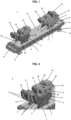
- FIG. 1 shows a perspective view of a rotating device 1 according to the invention.
- the rotating device has a base body 2 and two support devices 3.
- the support devices each have a base 4.
- the base 4 is formed from two base elements 4a, 4b, each of which has a triangular longitudinal section, i.e. is designed as a three-sided prism.
- the base 4 is fastened to the top 15 of the base body 2.
- a first rocking element 5 is pivotally mounted on the base 4 via a first axis 7.
- the first rocking element 5 has two main pivot arms 8 and 11.
- a boom 9 is arranged on the first main pivot arm 8.
- the first main pivot arm 8 and the boom 9 are integrally connected to one another in this embodiment and the boom 9 represents a continuation of the first main pivot arm.
- a roller 10 is rotatably mounted on a roller axis 31.
- the second main pivot arm 11 is oriented towards the center of the rotating device, i.e. towards the other support device.
- At the end of the second main pivot arm 11 there is a mount for a second axis 21.
- a second rocking element 6 is pivotally mounted on the second axis 21.
- the second rocking element has two pivot arms.
- At each end of the pivot arms a roller 24 is rotatably mounted on a roller axis 30.
- the base body 12 stands on the floor. For this purpose it has feet 14 as a support surface, which stand on the floor.
- Figure 2 shows a perspective view of a support device 3 from Figure 1 .
- the first rocker element 5 is mounted on the base 4 via the first axis 7.
- the first main pivot arm 8 extends outwards to the left of the centre of the rotating device in the figure.
- the first pivot arm 8 is extended to form the boom 9.
- the first rocker element 5 is formed by four side supports 12 arranged parallel to one another and connected to one another, which include both the main pivot arms and the booms.
- the two inner side supports 12 are connected to one another via a stabilizing element 13.
- the outer roller 10 is arranged between the two inner side supports 12.
- the first axis 7 runs through all four side supports, as do the second axis 21 and the roller axis 31 of the outer roller 10.
- the second rocker element 6 is pivotally mounted on the second axis 21.
- the second rocker element 6 is formed from two side supports 25 arranged parallel to one another and connected to one another.
- the side supports 25 are connected to one another centrally between the rollers 24 via a stabilizing element 26.
- the side supports form the two swivel arms of the second rocker element.
- the second axle 21 and the roller axles 30 lead through both side supports 25.
- the two second rocker elements are each arranged on the inside of the support device towards the center of the rotating device, while the arms of the first rocker element each point towards the outside of the rotating device as a load arm.
- the side supports 25 of the second rocker element are each arranged between an outer and an inner side support 12 of the first rocker device.
- Figure 3 shows a support device 3 according to the invention in a side view.
- the first rocker element 5 is pivoted to the right so that the boom 9 on the first main pivot arm 8 points upwards.
- the short main pivot arm 11 is pivoted downwards.
- the second rocker element 6 is aligned centrally.
- the two pivot arms 22 and 23 of the second rocker element are designed to be mirror-symmetrical in this embodiment.
- FIG. 4 shows a rotating device 1 according to the invention with a pipe 100 resting on it in a schematic representation.
- the rotating device 1 has two support devices 3.
- the support devices 3 have a base 4 which is mounted on a base body 2 (not shown).
- the support devices 3 are each pivoted on the main pivot axis which runs through the first axis 7, towards the pipe, ie towards the central axis of the base body 2.
- the pipe 100 rests exclusively on the six rollers 10 and 24 of the rotating device.
- the rollers 10 and 24 form the only support points for the pipe 100, so that when a pipe 100 is placed on the rotating device, only the rollers rest on the pipe surface.
- Each roller has a roller axis and a rotation axis running through the roller axis.
- the rotation axes of the rollers run parallel to each other and parallel to the longitudinal axis of a pipe mounted on the rotating device.
- the direction of rotation of the pipe is indicated by arrow D.
- rotating device 1 base body 2 carrying device 3 base 4 first rocker element 5 second rocker element 6 first axis 7 first main swivel arm 8 boom 9 role 10 second main swivel arm 11 side carrier 12 stabilizing element 13 stand 14 top of the base body 15 second axis 21 swivel arm 22 swivel arm 23 role 24 side carrier 25 stabilizing element 26 roller axle 30 roller axle 31 Pipe 100 direction of rotation of the pipe D
Landscapes
- Engineering & Computer Science (AREA)
- Mechanical Engineering (AREA)
- General Engineering & Computer Science (AREA)
- Physics & Mathematics (AREA)
- Optics & Photonics (AREA)
- Jib Cranes (AREA)
- Bending Of Plates, Rods, And Pipes (AREA)
- Supports For Pipes And Cables (AREA)
- Support Of The Bearing (AREA)
Description
- Die Erfindung betrifft eine Drehvorrichtung zur Drehung von Rohren mit großem Durchmesser um ihre Längsachse gemäß dem Oberbegriff von Anspruch 1.
- Großrohre, insbesondere aus längs- und rundnahtgeschweißten Stahlblechen, mit einem erheblichen Durchmesser werden beispielsweise in der Erdölindustrie oder bei der Herstellung von großen Bauwerken aus Metall verwendet. Ein wichtiges Einsatzgebiet ist der Fundamentbau für Offshore-Anlagen, insbesondere Windkraftanlagen. Für Großrohre, die im Offshore - Bereich eingesetzt werden, z.B. als Monopiles oder Tripode, sind Rohrdurchmesser von größer 6 m und mittlerweile größer als 9 m keine Seltenheit mehr. Im Verhältnis zum Rohrdurchmesser sind diese großen Rohre sehr dünnwandig ausgebildet.
- Vor dem Einsatz werden die Rohre in verschiedenen Arbeitsschritten hergestellt und für den Einsatz abhängig vom Anwendungszweck vorbereitet. Für den Einsatz im Offshore-Bereich werden beispielweise Korrosionsschutzbeschichtungen aufgetragen, um das Rohr vor der Korrosion im Salzwasser zu schützen. Angesichts der Dimensionen des Rohrs erfolgt die Beschichtung während das Rohr liegt. Um die gesamte Oberfläche beschichten zu können, muss das Rohr während des Beschichtungsvorgangs um seine Längsachse gedreht werden. Hierfür wird das Rohr auf Drehvorrichtungen aufgelegt. Die Drehvorrichtungen müssen eine ausreichende Tragfähigkeit aufweisen, um die sehr großen und schweren Rohre tragen zu können. Da die Rohre im Vergleich zu den großen Durchmessern und hohen Massen nur eine geringe Wanddicke aufweisen, besitzen sie eine geringe radiale Steifigkeit. Es besteht daher die Gefahr, dass es bei der Lagerung auf der Drehvorrichtung oder beim Drehen zu einem Einbeulen oder einer Beschädigung der Oberfläche des Rohrs kommt. Auch können beim Drehen des Rohrs zu hohe Spannungen am Rohr auftreten, die zu einer irreversiblen Beschädigung des Rohrs führen. Viele herkömmliche Drehvorrichtungen besitzen bereits keine ausreichende Tragfähigkeit vor dem Hintergrund der derzeitigen Großrohr-Gewichte. Einige Drehvorrichtungen sind zudem für genau einen Rohrdurchmesser ausgelegt, so dass für Rohre mit verschiedenen Rohrdurchmessern verschiedene Drehvorrichtungen bereitgehalten werden müssen.
-
DE 10 2022 103 490 beschreibt eine Drehvorrichtung zur Drehung von Rohren mit großem Durchmesser um ihre Längsachse. Die Mehrfachdrehvorrichtung weist 6 bis 10 Rollen auf, wobei die Drehachsen der Rollen auf einem Kreisbogen angeordnet sind. Die Rollen sind an einem Grundrahmen nebeneinander aufgereiht. Mit der beschriebenen Drehvorrichtung ist es möglich Rohre mit Rohrdurchmessern von mindestens 6 m trotz ihres Gewichts und ihrer Größe sicher und beschädigungsfrei zu drehen, ohne dass es zu Einbeulungen oder Beschädigungen der Rohroberfläche kommt. Die Drehvorrichtung weist allerdings eine große Zahl von Bauteilen und Rollen auf, so dass sie ein hohes Eigengewicht hat und relativ viel Material für die Fertigung benötigt wird. Weitere bekannte Vorrichtungen sind inCN 114 832 961 A ,CN 114 042 576 A undCN 112 403 755 B beschrieben. - Aufgabe der Erfindung ist es eine Drehvorrichtung bereit zu stellen, die die vorstehenden Nachteile überwindet und insbesondere eine beschädigungsfreie Lagerung und sichere und gleichmäßige Drehung von Rohren, wie Monopiles oder Stahlrohren, mit einem Durchmesser von mindestens 6 m ermöglicht, ohne dass es zu einer Verformung des Rohrs, wie Eindellungen bzw. Einbuchtungen kommt. Die Drehvorrichtung soll zudem flexibel für verschiedene Rohrdurchmesser einsetzbar sein und aus relativ wenigen Bauteilen aufgebaut sein.
- Hauptmerkmale der Erfindung sind im kennzeichnenden Teil von Anspruch 1 angegeben. Weitere Ausführungsformen sind Gegenstand der Unteransprüche oder nachfolgend beschrieben.
- Die erfindungsgemäße Drehvorrichtung zur Drehung von Rohren mit großem Durchmesser um ihre Längsachse weist einen Grundkörper auf und zwei Tragvorrichtungen, die am Grundkörper angeordnet sind, wobei jede Tragvorrichtung einen Sockel und mindestens ein Wippelement umfasst. Das Wippelement ist schwenkbar auf einer Achse gelagert. Die Achse ist in einer Aufnahme des Sockels angeordnet und der Sockel ist mit dem Grundkörper verbunden. Jede der beiden Tragvorrichtungen hat ein erstes Wippelement und ein zweites Wippelement. Das erste Wippelement weist eine erste Achse auf und ist auf der ersten Achse in der Aufnahme des Sockels schwenkbar gelagert, wobei eine Hauptschwenkachse der Tragvorrichtung durch die erste Achse verläuft. Das erste Wippelement weist zwei Hauptschwenkarme auf, die sich von der ersten Achse erstrecken und in einem festen Winkel zueinander angeordnet sind. Ein erster Hauptschwenkarm des ersten Wippelements hat einen Ausleger. Der Ausleger ist als Fortsetzung des Schwenkarms ausgebildet und verlängert diesen. Am äußeren Ende des Auslegers, das am weitesten von der ersten Achse entfernt ist, ist eine Rollenachse angeordnet, auf der eine Rolle drehbar am Ausleger gelagert ist. Ein zweiter Hauptschwenkarm des ersten Wippelements weist an einem Ende eine Aufnahme für eine zweite Achse auf. Auf der zweiten Achse ist ein zweites Wippelement schwenkbar gelagert. Durch die zweite Achse verläuft eine Nebenschwenkachse der Tragvorrichtung. Das zweite Wippelement weist zwei Schwenkarme auf, die sich von der zweiten Achse erstrecken und in einem festen Winkel zueinander angeordnet sind. An jedem Schwenkarm des zweiten Wippelements ist jeweils eine Rollenachse angeordnet, auf der eine Rolle drehbar am Schwenkarm gelagert ist. Die Hauptschwenkachse und die Nebenschwenkachse verlaufen parallel zueinander. Die Tragvorrichtung kann um beide Schwenkachsen unabhängig voneinander geschwenkt werden. Jede Rolle hat eine Rollenachse und eine durch die Rollenachse verlaufende Drehachse, wobei die Drehachsen der Rollen parallel zueinander und parallel zur Längsachse eines auf der Drehvorrichtung gelagerten Rohrs verlaufen. Nur die Rollen bilden die Auflagepunkte für ein Rohr, so dass beim Auflegen eines Rohrs auf die Drehvorrichtung nur die Rollen an der Rohroberfläche anliegen.
- Der Grundkörper stellt die Basis der Drehvorrichtung dar, die auf dem Boden oder auf einem Transportfahrzeug oder anderen Unterlage steht. Der Grundkörper hat eine Oberseite auf der die Tragvorrichtungen montiert sind. Bevorzugt ist die Oberseite als plane Fläche ausgebildet, z.B. mit einem etwa rechteckigen Grundriss. Die plane Fläche kann z.B. als Gleitfläche zum stufenlosen Verstellen der Tragvorrichtungen gestaltet sein und/oder mit äquidistant verteilten Bohrungen zum Fixieren der Tragvorrichtungen mittels Steckbolzen. Der Grundkörper kann an seiner Unterseite Standfüße aufweisen mit denen er auf dem Untergrund steht. Zusätzlich können am Grundkörper weitere Bauteile, wie z.B. Anschlagelemente zum Befestigen an einem Kran vorgesehen sein.
- Bevorzugt sind die Rollenachsen am äußersten Ende des Auslegers von der ersten Achse aus und jeweils am äußersten Ende der Schwenkarme des zweiten Wippelements von der zweiten Achse aus angeordnet, so dass die Rollen über den Ausleger und das zweite Wippelement hinausragen und die Rollen in Richtung des Rohrs die Auflagepunkte für das Rohr bilden.
- Die Rollen sind in einer Ausführungsform als Mitläuferrollen ausgestaltet und weisen keinen Antrieb auf. In einer weiteren Ausführungsform sind die Rollen als angetriebene Rollen ausgestaltet.
- Jede der beiden Tragvorrichtungen umfasst einen Sockel und zwei Wippelemente, sowie insgesamt drei Rollen. Der Sockel der Tragvorrichtung weist eine Aufnahme auf, die als Achslager ausgebildet ist. In der Aufnahme ist ein erstes Wippelement auf einer ersten Achse schwenkbar gelagert, wobei durch die erste Achse die Hauptschwenkachse der Tragvorrichtung verläuft. Das erste Wippelement weist zwei Hauptschwenkarme auf. Die Hauptschenkarme sind bevorzugt gleich lang und weisen die gleiche Grundform auf. Weiter bevorzugt sind sie integral miteinander verbunden. Der erster Hauptschwenkarm des ersten Wippelements hat einen Ausleger. Am Ende des Auslegers ist eine Rolle angeordnet. Die Rolle weist eine Rollenachse auf, auf der sie drehbar am Ausleger gelagert ist. Der zweite Hauptschwenkarm weist eine Aufnahme für eine zweite Achse auf, wobei die Aufnahme als Achslager ausgebildet ist. Ein zweites Wippelement ist auf dieser zweiten Achse gelagert. Das zweite Wippelement ist an einem Ende des zweiten Hauptschwenkarms angeordnet. Durch die zweite Achse verläuft eine Nebenschwenkachse der Tragvorrichtung. Das zweite Wippelement weist zwei Schwenkarme auf, die in einem festen Winkel zueinander angeordnet sind. Die Schwenkarme sind bevorzugt gleich lang und weisen die gleiche Grundform auf. Weiter bevorzugt sind sie integral miteinander verbunden. An den Enden der Schwenkarme des zweiten Wippelements ist jeweils eine Rolle angeordnet. Jede Rolle weist eine Rollenachse auf, auf der sie drehbar am Schwenkarm gelagert ist. Die Schwenkarme des zweiten Wippelements sind in einer bevorzugten Ausführung spiegelsymmetrisch ausgebildet, wobei die Spiegelebene durch die zweite Achse verläuft.
- Das Wippelement umfasst bevorzugt mindestens zwei parallele und miteinander verbundene Seitenträger, wobei die Rolle zwischen den Seitenträgern angeordnet ist. Das erste Wippelement umfasst in einer Ausführungsform vier parallele in weiten Teilen deckungsgleiche Seitenträger. Die Seitenträger umfassen sowohl die Hauptschwenkarme, als auch den Ausleger. Es gibt in dieser Ausführungsform zwei äußere Seitenträger, die die Außenseiten des ersten Wippelements bilden und zwei innere Seitenträger. Die beiden inneren Seitenträger können über ein oder mehrere Stabilisierungselemente miteinander verbunden sein. Die äußere Rolle, das ist die am Ausleger gelagerte Rolle, ist dann zwischen den beiden inneren Seitenträgern angeordnet. Die erste Achse und die zweite Achse führen durch alle vier Seitenträger, ebenso wie die Rollenachse der äußeren Rolle.
- Das zweite Wippelement umfasst in einer Ausführungsform bevorzugt zwei parallele in weiten Teilen deckungsgleiche Seitenträger. Die Seitenträger können über ein oder mehrere Stabilisierungselemente miteinander verbunden sein. Die Seitenträger bilden die beiden Schwenkarme des zweiten Wippelements. Die zweite Achse und die Rollenachsen führen durch beiden Seitenträger. Die Seitenträger des zweiten Wippelements sind beispielsweise jeweils zwischen einem äußeren und einem inneren Seitenträger der ersten Wippvorrichtung angeordnet.
- In einer Ausführungsform ist der Sockel der Tragvorrichtung fest mit dem Grundkörper verbunden, z.B. mit dem Grundkörper verschweißt.
- In einer weiteren Ausführungsform ist der Sockel der Tragvorrichtung verstellbar am Grundkörper montiert, bevorzugt ist er mit Verbindungselementen in Öffnungen des Grundkörpers montiert. Der Sockel ist in dieser Ausführungsform lösbar an dem Grundkörper befestigt, so dass seine Position auf dem Grundkörper verstellt werden kann. Der Grundkörper weist hierfür bevorzugt rasterförmige Öffnungen, schlitzförmige Öffnungen oder eine Montageschiene zur Aufnahme der Verbindungselemente auf, so dass eine stufenlose oder stufenweise Einstellung des Abstands zwischen den Tragvorrichtungen auf dem Grundkörper möglich ist. Es ist auch möglich einen Sockel einer ersten Tragvorrichtung fest mit dem Grundkörper zu verbinden und den Sockel einer zweiten Tragvorrichtung verstellbar zu gestalten. Der Abstand kann bei dieser Ausführung nur durch Verstellen der Position einer Tragvorrichtung auf dem Grundkörper und somit wenig Montageaufwand erreicht werden.
- Die Tragvorrichtungen sind bevorzugt spiegelsymmetrisch auf dem Grundkörper positioniert bezogen auf eine Mittelachse M des Grundkörpers, wobei der Ausleger des ersten Wippelements jeweils zur Außenseite des Grundkörpers angeordnet ist und die zweiten Wippelemente jeweils auf der zur Mittelachse weisenden Seite angeordnet sind. Die beiden zweiten Wippelement sind somit jeweils auf der Innenseite der Tragvorrichtung zur Mitte der Drehvorrichtung hin angeordnet, während die Ausleger des ersten Wippelements jeweils als Lastarm zur Außenseite der Drehvorrichtung weisen.
- Die erfindungsgemäße Drehvorrichtung wird zum Drehen (Rotation um die Längsachse) von längsnaht- und rundnahtverschweißten Stahlrohren mit großen Durchmessern, sogenannten Großrohren, und Großrohrschüssen mit einem Rohrdurchmesser von mindestens 6 m, bevorzugt mindestens 8 bis 10 m verwendet. Auch Rohrdurchmesser bis 12 m und darüber hinaus, wie sie z.B. bei schwimmenden Offshore Gründungsstrukturen (Spar buoys) auftreten, können mit der Drehvorrichtung gedreht werden. Längsnahtverschweißte Großrohrschüsse werden aus Stahlblechtafeln hergestellt. Der Blechtafelzuschnitt wird zunächst rundgebogen und die offenen Kanten des so entstandenen geschlitzten Rohrschusses werden mit einer provisorischen Naht zusammengeheftet (Heftnaht), welche später in Produktionsprozess wieder entfernt wird. Der heftgeschweißte Rohrschuss wird an einem Schweißplatz positioniert und zunächst die Innennaht und dann die Außennaht am Rohrschuss angebracht. Anschließend kann das Rohr weiterbearbeitet, z.B. beschichtet werden.
- Die Rohre weisen bei üblicher Bauweise eine Wanddicke von 35 mm bis 250 mm, bevorzugt 40 bis 200 mm, besonders bevorzugt 50 mm bis 170 mm auf. Großrohre und Großrohrschüsse mit einem Durchmesser von 6 m bis 10 m haben bevorzugt eine Wanddicke von 50 mm bis 170 mm. Ein Großrohrschuss hat üblicherweise eine Länge von 2 m bis 4,2 m. Die Rohre werden aus einer Vielzahl von Rohrschüssen zusammengeschweißt und weisen dabei Längen von bis zu 120 m auf. Die Rohre wiegen in diesen Dimensionen im Mittel über tausend Tonnen. Mit der erfindungsgemäßen Drehvorrichtung ist es möglich diese Rohre trotz ihres Gewichts und ihrer Größe sicher und beschädigungsfrei zu drehen, ohne dass es zu Einbeulungen oder Beschädigungen der Rohroberfläche kommt.
- Der Grundkörper und ggf. die Tragvorrichtungen bestehen bevorzugt aus Stahl, besonders bevorzugt aus Baustahl. Besonders bevorzugt bestehen der Grundkörper und die Tragvorrichtungen aus Stahl.
- Die Tragvorrichtung kann um zwei Achsen, nämlich die Hauptschwenkachse und die Nebenschwenkachse schwenken und sich so dem Durchmesser des aufgelegten Rohrs anpassen. Durch das Schwenken der Wippelement wird die Position der Rollen verändert. Beim Aufsetzen des Rohrs auf die Drehvorrichtung berührt das Rohr als erstes die Rolle im zweiten Wippelement, die zur Mitte gerichtet ist. Durch das Gewicht des Rohrs wird die Rolle nach unten gedrückt und das zweite Wippelement schwenkt um die Nebenschwenkachse nach unten, solange bis die weitere im zweiten Wippelement angeordnete Rolle ebenfalls an der Rohroberfläche anliegt. Gleichzeitig wird durch das Gewicht auch das erste Wippelement nach unten gedrückt und schwenkt um die Hauptschwenkachse ebenfalls nach unten zur Mitte, bis auch die äußere Rolle am Ausleger an der Rohroberfläche anliegt. Die Größe der Schwenkung um die Schwenkachse hängt dabei vom Rohrdurchmesser und dem Abstand der Tragvorrichtungen zueinander ab. Die Wippelemente schwenken jeweils um die Schwenkachse als Drehpunkt, wobei die Schwenkbewegung um einen Auslenkwinkel bis zu einem Anschlag erfolgt.
- Die erfindungsgemäße Drehvorrichtung passt sich bedingt durch die Wippelemente an verschiedene Rohrdurchmesser an, so dass kein Austausch der Drehvorrichtung notwendig ist und nicht mehrere Drehvorrichtungen für verschiedene Rohrdurchmesser bereitgehalten werden müssen. Dieses ermöglicht einen flexiblen Einsatz durch Variabilität der Drehvorrichtung für unterschiedliche Rohrdurchmesser ohne Umbauaufwand. Bei großen Unterschieden zwischen den Rohrdurchmessern ist die Drehvorrichtung in der Ausführung mit verstellbaren Sockeln zudem mit wenigen Umbauschritten an andere Rohrdurchmesser anpassbar.
- Gegenstand der Erfindung ist weiterhin ein System aufweisend mindestens 2 Drehvorrichtungen gemäß einem der Patentansprüche 1 bis 7 und ein Rohr mit einem Rohrdurchmesser von mindestens 8 m.
- Die erfindungsgemäße Drehvorrichtung wird in Ausführungsbeispielen anhand der Zeichnungen näher erläutert. Es zeigen:
- Fig. 1
- eine Ausführungsform einer erfindungsgemäßen Drehvorrichtung,
- Fig. 2
- einen Ausschnitt aus einer erfindungsgemäßen Drehvorrichtung in perspektivischer Ansicht,
- Fig. 3
- einen Ausschnitt aus einer erfindungsgemäßen Drehvorrichtung in Seitenansicht und
- Fig. 4
- eine Seitenansicht einer erfindungsgemäßen Drehvorrichtung mit aufliegendem Rohr.
-
Figur 1 zeigt eine perspektivische Ansicht einer erfindungsgemäßen Drehvorrichtung 1. Die Drehvorrichtung weist einen Grundkörper 2 und zwei Tragvorrichtungen 3 auf. Die Tragvorrichtungen haben jeweils einen Sockel 4. Der Sockel 4 wird aus zwei Sockelelementen 4a, 4b gebildet, die jeweils einen dreieckigen Längsschnitt haben, d.h. als dreiseitiges Prisma ausgestaltet sind. Der Sockel 4 ist auf der Oberseite 15 des Grundkörpers 2 befestigt. Am Sockel 4 ist jeweils über eine erste Achse 7 ein erstes Wippelement 5 schwenkbar gelagert. Das erste Wippelement 5 hat zwei Hauptschenkarme 8 und 11. Am ersten Hauptschwenkarm 8 ist ein Ausleger 9 angeordnet. Der erste Hauptschwenkarm 8 und der Ausleger 9 sind in dieser Ausführungsform integral miteinander verbunden und der Ausleger 9 stellt eine Fortsetzung des ersten Hauptschwenkarms dar. Am Ende des Auslegers 9 ist eine Rolle 10 auf einer Rollenachse 31 drehbar gelagert. Der zweite Hauptschenkarm 11 ist zur Mitte der Drehvorrichtung d.h. zur anderen Tragvorrichtung orientiert. Am Ende des zweiten Hauptschwenkarms 11 ist eine Aufnahme für eine zweite Achse 21 angeordnet. Auf der zweiten Achse 21 ist ein zweites Wippelement 6 schwenkbar gelagert. Das zweite Wippelement weist zwei Schwenkarme auf. An den Enden der Schwenkarme ist jeweils eine Rolle 24 auf einer Rollenachse 30 drehbar gelagert. Der Grundkörper 12 steht auf dem Boden. Hierzu weist er Standfüße 14 als Aufstandsfläche auf, die auf dem Boden stehen. -
Figur 2 zeigt eine perspektivische Ansicht einer Tragvorrichtung 3 ausFigur 1 . Am Sockel 4 ist über die erste Achse 7 das erste Wippelement 5 montiert. Der erste Hauptschwenkarm 8 erstreckt sich in der Figur nach links von der Mitte der Drehvorrichtung weg nach außen. Der erste Schwenkarm 8 ist verlängert um den Ausleger 9 zu bilden. Das erste Wippelement 5 wird von vier parallel zueinander angeordneten, miteinander verbundenen Seitenträgern 12 gebildet, die sowohl die Hauptschwenkarme, als auch die Ausleger umfassen. Es gibt zwei äußere Seitenträger, die die Außenseiten des ersten Wippelements bilden, und zwei innere Seitenträger. Die beiden inneren Seitenträger 12 sind über ein Stabilisierungselement 13 miteinander verbunden. Die äußere Rolle 10 ist zwischen den beiden inneren Seitenträgern 12 angeordnet. Die erste Achse 7 führt durch alle vier Seitenträger, ebenso wie die zweite Achse 21 und die Rollenachse 31 der äußeren Rolle 10. Auf der zweiten Achse 21 ist das zweite Wippelement 6 schwenkbar gelagert. Das zweite Wippelement 6 wird aus zwei parallel zueinander angeordneten, miteinander verbundenen Seitenträgern 25 gebildet. Die Seitenträger 25 sind mittig zwischen den Rollen 24 über ein Stabilisierungselement 26 miteinander verbunden. Die Seitenträger bilden die beiden Schwenkarme des zweiten Wippelements. Die zweite Achse 21 und die Rollenachsen 30 führen durch beiden Seitenträger 25. Die beiden zweiten Wippelemente sind jeweils auf der Innenseite der Tragvorrichtung zur Mitte der Drehvorrichtung hin angeordnet, während die Ausleger des ersten Wippelements jeweils als Lastarm zur Außenseite der Drehvorrichtung weisen. Die Seitenträger 25 des zweiten Wippelements sind jeweils zwischen einem äußeren und einem inneren Seitenträger 12 der ersten Wippvorrichtung angeordnet. -
Figur 3 zeigt eine erfindungsgemäße Tragvorrichtung 3 in einer Seitenansicht. Das erste Wippelement 5 ist nach rechts geschwenkt, so dass der Ausleger 9 am ersten Hauptschwenkarm 8 nach oben zeigt. Der kurze Hauptschwenkarm 11 ist nach unten geschwenkt. Das zweite Wippelement 6 ist mittig ausgerichtet. Die beiden Schwenkarme 22 und 23 des zweiten Wippelements sind in dieser Ausführungsform spiegelsymmetrisch ausgestaltet. -
Figur 4 zeigt eine erfindungsgemäße Drehvorrichtung 1 mit aufliegendem Rohr 100 in einer schematischen Darstellung. Die Drehvorrichtung 1 weist zwei Tragvorrichtungen 3 auf. Die Tragvorrichtungen 3 haben einen Sockel 4, der auf einem Grundkörper 2 (nicht dargestellt) montiert ist. Die Tragvorrichtungen 3 sind jeweils an der Hauptschwenkachse, die durch die erste Achse 7 verläuft, zum Rohr d.h. zur Mittelachse des Grundkörpers 2 geschwenkt. Das Rohr 100 liegt ausschließlich auf den sechs Rollen 10 und 24 der Drehvorrichtung auf. Die Rollen 10 und 24 bilden die einzigen Auflagepunkte für das Rohr 100, so dass beim Auflegen eines Rohrs 100 auf die Drehvorrichtung nur die Rollen an der Rohroberfläche anliegen. - Jede Rolle weist eine Rollenachse und eine durch die Rollenachse verlaufende Drehachse auf. Die Drehachsen der Rollen verlaufen parallel zueinander und parallel zur Längsachse eines auf der Drehvorrichtung gelagerten Rohrs. Die Drehrichtung des Rohrs ist durch den Pfeil D angezeigt.
- Die Erfindung ist nicht auf eine der vorbeschriebenen Ausführungsformen beschränkt, sondern in vielfältiger Weise abwandelbar.
-
Drehvorrichtung 1 Grundkörper 2 Tragvorrichtung 3 Sockel 4 erstes Wippelement 5 zweites Wippelement 6 erste Achse 7 erster Hauptschwenkarm 8 Ausleger 9 Rolle 10 zweiter Hauptschwenkarm 11 Seitenträger 12 Stabilisierungselement 13 Standfuß 14 Oberseite Grundkörper 15 zweite Achse 21 Schwenkarm 22 Schwenkarm 23 Rolle 24 Seitenträger 25 Stabilisierungselement 26 Rollenachse 30 Rollenachse 31 Rohr 100 Drehrichtung Rohr D
Claims (8)
- Drehvorrichtung (1) zur Drehung von Rohren mit großem Durchmesser um ihre Längsachse, aufweisend- einen Grundkörper (2),- zwei Tragvorrichtungen (3), die auf dem Grundkörper (2) angeordnet sind,
wobei jede Tragvorrichtung (3) einen Sockel (4) und mindestens ein Wippelement umfasst, das schwenkbar in einer Aufnahme des Sockels gelagert ist und- der Sockel (4) mit dem Grundkörper (2) verbunden ist,dadurch gekennzeichnet, dass- jede Tragvorrichtung (3) ein erstes Wippelement (5) und ein zweites Wippelement (6) umfasst,- das erstes Wippelement (5) eine erste Achse (7) aufweist und auf der ersten Achse (7) in der Aufnahme des Sockels schwenkbar gelagert ist, wobei eine Hauptschwenkachse durch die erste Achse (7) verläuft,- das erste Wippelement (5) zwei Hauptschwenkarme (8, 11) aufweist, die sich von der ersten Achse (7) erstrecken und in einem festen Winkel zueinander angeordnet sind,- ein erster Hauptschwenkarm (8) des ersten Wippelements einen Ausleger (9) aufweist und am äußeren Ende des Auslegers (9) eine Rollenachse (31) angeordnet ist, auf der eine Rolle (10) drehbar am Ausleger gelagert ist,- ein zweiter Hauptschwenkarm (11) des ersten Wippelements an einem Ende eine Aufnahme für eine zweite Achse (21) aufweist,- ein zweites Wippelement (6) auf der zweiten Achse (21) schwenkbar gelagert ist, wobei durch die zweite Achse (21) eine Nebenschwenkachse verläuft,- das zweite Wippelement (6) zwei Schwenkarme (22, 23) aufweist, die sich von der zweiten Achse erstrecken und in einem festen Winkel zueinander angeordnet sind,- an jedem Schwenkarm (22, 23) des zweiten Wippelements jeweils eine Rollenachse (30) angeordnet ist und auf jeder Rollenachse (30) eine Rolle (24) drehbar am Schwenkarm gelagert ist,- die Hauptschwenkachse und die Nebenschwenkachse parallel zueinander verlaufen,- jede Rolle (10, 24) eine Rollenachse (30, 31) und eine durch die Rollenachse verlaufende Drehachse aufweisen und die Drehachsen der Rollen (10, 24) parallel zueinander und parallel zur Längsachse eines auf der Drehvorrichtung gelagerten Rohrs (100) verlaufen und- die Rollen (10, 24) Auflagepunkte für ein Rohr (100) bilden, so dass beim Auflegen eines Rohrs (100) auf die Drehvorrichtung (1) nur die Rollen (10,24) an der Rohroberfläche anliegen. - Drehvorrichtung (1) gemäß Patentanspruch 1 dadurch gekennzeichnet, dass die Schwenkarme (22, 23) des zweiten Wippelements (6) spiegelsymmetrisch zueinander ausgebildet sind.
- Drehvorrichtung (1) gemäß Patentanspruch 1 oder 2 dadurch gekennzeichnet, dass das Wippelement (5, 6) mindestens zwei parallele und miteinander verbundene Seitenträger (12, 25) umfasst und die Rolle (10, 24) zwischen den Seitenträgern (12, 25) angeordnet ist.
- Drehvorrichtung (1) gemäß einem der vorhergehenden Patentansprüche dadurch gekennzeichnet, dass der Sockel (4) fest mit dem Grundkörper (2) verbunden ist.
- Drehvorrichtung (1) gemäß einem der Patentansprüche 1 bis 3 dadurch gekennzeichnet, dass der Sockel (4) mit Verbindungselementen am Grundkörper montiert ist, bevorzugt verstellbar montiert ist, und der Grundkörper bevorzugt rasterförmige Öffnungen, schlitzförmige Öffnungen oder eine Montageschiene zur Aufnahme der Verbindungselemente aufweist.
- Drehvorrichtung (1) gemäß einem der vorhergehenden Patentansprüche dadurch gekennzeichnet, dass die Tragvorrichtungen (3) spiegelsymmetrisch auf dem Grundkörper (2) positioniert sind bezogen auf eine Mittelachse (M) des Grundkörpers, wobei der Ausleger (9) des ersten Wippelements (5) jeweils zur Außenseite des Grundkörpers angeordnet ist und die zweiten Wippelemente (6) jeweils auf der zur Mittelachse weisenden Seite angeordnet sind.
- Drehvorrichtung (1) gemäß einem der vorhergehenden Patentansprüche, dadurch gekennzeichnet, dass die Rollenachsen (30) am äußersten vertikalen des Auslegers und des zweiten Wippelements angeordnet sind und die Rollen (10, 24) über den Ausleger und das zweite Wippelement hinausragen, so dass die Rollen (10, 24) in Richtung des Rohrs den äußersten Kontaktpunkt bilden.
- System aufweisend mindestens 2 Drehvorrichtungen gemäß einem der Patentansprüche 1 bis 7 und ein Rohr mit einem Rohrdurchmesser von mindestens 8 m.
Priority Applications (9)
| Application Number | Priority Date | Filing Date | Title |
|---|---|---|---|
| PL22192206.5T PL4327952T3 (pl) | 2022-08-25 | 2022-08-25 | Urządzenie obrotowe do rur i odcinków rur |
| ES22192206T ES3017069T3 (en) | 2022-08-25 | 2022-08-25 | Rotating device for pipes and pipe lengths |
| EP22192206.5A EP4327952B1 (de) | 2022-08-25 | 2022-08-25 | Drehvorrichtung für rohre und rohrschüsse |
| CA3208703A CA3208703A1 (en) | 2022-08-25 | 2023-08-09 | Turning device for pipes and pipe elements |
| US18/235,501 US12172244B2 (en) | 2022-08-25 | 2023-08-18 | Turning device for pipes and pipe elements |
| BR102023016838-8A BR102023016838A2 (pt) | 2022-08-25 | 2023-08-22 | Dispositivo de giro e sistema |
| JP2023135136A JP2024031909A (ja) | 2022-08-25 | 2023-08-23 | パイプの回転装置およびパイプシステム |
| TW112132070A TWI922833B (zh) | 2022-08-25 | 2023-08-25 | 旋轉設備以及用於旋轉管的系統 |
| KR1020230112277A KR20240028961A (ko) | 2022-08-25 | 2023-08-25 | 파이프 및 파이프 요소를 위한 회전 장치 |
Applications Claiming Priority (1)
| Application Number | Priority Date | Filing Date | Title |
|---|---|---|---|
| EP22192206.5A EP4327952B1 (de) | 2022-08-25 | 2022-08-25 | Drehvorrichtung für rohre und rohrschüsse |
Publications (3)
| Publication Number | Publication Date |
|---|---|
| EP4327952A1 EP4327952A1 (de) | 2024-02-28 |
| EP4327952C0 EP4327952C0 (de) | 2024-12-25 |
| EP4327952B1 true EP4327952B1 (de) | 2024-12-25 |
Family
ID=83081205
Family Applications (1)
| Application Number | Title | Priority Date | Filing Date |
|---|---|---|---|
| EP22192206.5A Active EP4327952B1 (de) | 2022-08-25 | 2022-08-25 | Drehvorrichtung für rohre und rohrschüsse |
Country Status (8)
| Country | Link |
|---|---|
| US (1) | US12172244B2 (de) |
| EP (1) | EP4327952B1 (de) |
| JP (1) | JP2024031909A (de) |
| KR (1) | KR20240028961A (de) |
| BR (1) | BR102023016838A2 (de) |
| CA (1) | CA3208703A1 (de) |
| ES (1) | ES3017069T3 (de) |
| PL (1) | PL4327952T3 (de) |
Families Citing this family (3)
| Publication number | Priority date | Publication date | Assignee | Title |
|---|---|---|---|---|
| PL3928919T3 (pl) * | 2020-06-26 | 2024-12-16 | Eew Special Pipe Constructions Gmbh | Urządzenie mocujące do elementów rurowych spawanych szwem wzdłużnym |
| CN120816252B (zh) * | 2025-09-18 | 2025-11-25 | 南通中远海运船务工程有限公司 | 一种大管焊接装置 |
| CN120845600B (zh) * | 2025-09-22 | 2026-01-27 | 常州市武进武南管道设备有限公司 | 基于石油管道安装的多级可调式管托支架 |
Family Cites Families (11)
| Publication number | Priority date | Publication date | Assignee | Title |
|---|---|---|---|---|
| US1763775A (en) * | 1927-08-12 | 1930-06-17 | Ric Wil Company | Supporting means for pipes in conduits |
| US2005701A (en) * | 1931-08-12 | 1935-06-18 | Ric Wil Company | Conduit construction |
| US1995716A (en) * | 1933-07-15 | 1935-03-26 | Fred L Dickey | Conduit |
| US3735973A (en) * | 1971-10-15 | 1973-05-29 | W E Petrie | Pipe support |
| DE3910757A1 (de) * | 1989-04-04 | 1990-10-11 | Lisega Gmbh | Rohrsattel zur abstuetzung von rohren, bauteilen u. dgl. |
| DE102004035909A1 (de) * | 2004-07-20 | 2006-02-16 | Siemens Ag | Rollenlager mit mindestens einer drehbaren Rolle |
| US20100287957A1 (en) * | 2009-05-12 | 2010-11-18 | Xuejie Liu | Pipe-in-Pipe in RCC for Subsea Transfer of Cryogenic Fluids |
| CN112403755B (zh) * | 2021-01-22 | 2021-05-04 | 山东科技职业学院 | 一种管材输送装置 |
| CN114042576A (zh) * | 2021-12-24 | 2022-02-15 | 浙江宏德智能装备科技有限公司 | 一种往复式喷涂设备 |
| DE102022103490A1 (de) | 2022-02-15 | 2023-08-17 | Eew Special Pipe Constructions Gmbh | Mehrfach-Drehvorrichtung für Stahlrohre mit großem Durchmesser |
| CN114832961A (zh) * | 2022-06-13 | 2022-08-02 | 临沂市海鑫化工设备有限公司 | 一种搪玻璃设备的自动喷粉装置 |
-
2022
- 2022-08-25 PL PL22192206.5T patent/PL4327952T3/pl unknown
- 2022-08-25 EP EP22192206.5A patent/EP4327952B1/de active Active
- 2022-08-25 ES ES22192206T patent/ES3017069T3/es active Active
-
2023
- 2023-08-09 CA CA3208703A patent/CA3208703A1/en active Pending
- 2023-08-18 US US18/235,501 patent/US12172244B2/en active Active
- 2023-08-22 BR BR102023016838-8A patent/BR102023016838A2/pt unknown
- 2023-08-23 JP JP2023135136A patent/JP2024031909A/ja active Pending
- 2023-08-25 KR KR1020230112277A patent/KR20240028961A/ko active Pending
Also Published As
| Publication number | Publication date |
|---|---|
| US12172244B2 (en) | 2024-12-24 |
| US20240066641A1 (en) | 2024-02-29 |
| EP4327952A1 (de) | 2024-02-28 |
| JP2024031909A (ja) | 2024-03-07 |
| BR102023016838A2 (pt) | 2024-03-05 |
| CA3208703A1 (en) | 2024-02-25 |
| KR20240028961A (ko) | 2024-03-05 |
| EP4327952C0 (de) | 2024-12-25 |
| PL4327952T3 (pl) | 2025-04-14 |
| TW202421278A (zh) | 2024-06-01 |
| ES3017069T3 (en) | 2025-05-12 |
Similar Documents
| Publication | Publication Date | Title |
|---|---|---|
| EP4327952A1 (de) | Drehvorrichtung für rohre und rohrschüsse | |
| DE102012110496A1 (de) | Elliptische Lagerhandhabungsvorrichtung | |
| DE3416823A1 (de) | Stativ mit einem zur hoehenverstellung schenkbaren ausleger | |
| CH637594A5 (de) | Traganordnung fuer grosse zylindrische lasteinheiten, insbesondere grossrohre. | |
| EP0226776A2 (de) | Verfahren zum Herstellen von Grossraumbehältern sowie dazu verwendbare Einzelsegmente und Ausrichtwerkzeug zum Ausrichten derselben | |
| EP3189907A1 (de) | Vorrichtung zum herstellen eines zylindrischen behälters mit grossem durchmesser, insbesondere eines silos | |
| EP0328909B1 (de) | Haltevorrichtung für Rohrschellen oder andere Rohrlager | |
| EP1183443A1 (de) | Versteifungsring für den turm einer windenergieanlage | |
| DE102022103490A1 (de) | Mehrfach-Drehvorrichtung für Stahlrohre mit großem Durchmesser | |
| EP0080625B1 (de) | Umlenkstation für in Verladeanlagen mit senkrechten und waagerechten Förderzweigen angeordnete Bandförderer mit einem durch ein Deckband abgeschlossenen Wellkantengurt | |
| EP4058392B1 (de) | Montagerahmen zum verlagern und fixieren in einem schacht | |
| DE2002015C3 (de) | Vorrichtung zum Längsschweißen von rohrförmigen Werkstücken | |
| DE1434804A1 (de) | Verfahren und Einrichtung zum Errichten von Speicheraufbauten | |
| DE8717735U1 (de) | Aufweitwerkzeug für Enden von dünnwandigen Blechrohren | |
| EP0635650A1 (de) | Kippbewegliche Laufrollenlagerung | |
| DE1902889A1 (de) | Verstellbare Antennen-Anlage | |
| DE102007038047A1 (de) | Kippvorrichtung | |
| EP3189906B1 (de) | Vorrichtung zum herstellen eines zylindrischen behälters mit grossem durchmesser, insbesondere eines silos | |
| EP3928919B1 (de) | Spannvorrichtung für längsnahtverschweisste rohrschüsse | |
| DE1452238B2 (de) | Vorrichtung zum fortlaufenden Verschweißen erhitzter Blechkanten | |
| EP0935120A2 (de) | Verfahren und Vorrichtung zur Bestimmung der Krümmung von Langgut | |
| DE2106291A1 (de) | Turmkran | |
| DE3503976A1 (de) | Flachglas-transportgestell fuer innenladerfahrzeuge | |
| EP1239172B1 (de) | Grossdrehlagerung mit Wälzkörpern | |
| DE102017011303B4 (de) | Kugellagermodul und Verfahren zur Montage eines Kugellagermoduls |
Legal Events
| Date | Code | Title | Description |
|---|---|---|---|
| PUAI | Public reference made under article 153(3) epc to a published international application that has entered the european phase |
Free format text: ORIGINAL CODE: 0009012 |
|
| STAA | Information on the status of an ep patent application or granted ep patent |
Free format text: STATUS: REQUEST FOR EXAMINATION WAS MADE |
|
| 17P | Request for examination filed |
Effective date: 20231004 |
|
| AK | Designated contracting states |
Kind code of ref document: A1 Designated state(s): AL AT BE BG CH CY CZ DE DK EE ES FI FR GB GR HR HU IE IS IT LI LT LU LV MC MK MT NL NO PL PT RO RS SE SI SK SM TR |
|
| GRAP | Despatch of communication of intention to grant a patent |
Free format text: ORIGINAL CODE: EPIDOSNIGR1 |
|
| STAA | Information on the status of an ep patent application or granted ep patent |
Free format text: STATUS: GRANT OF PATENT IS INTENDED |
|
| INTG | Intention to grant announced |
Effective date: 20240712 |
|
| GRAS | Grant fee paid |
Free format text: ORIGINAL CODE: EPIDOSNIGR3 |
|
| GRAA | (expected) grant |
Free format text: ORIGINAL CODE: 0009210 |
|
| STAA | Information on the status of an ep patent application or granted ep patent |
Free format text: STATUS: THE PATENT HAS BEEN GRANTED |
|
| AK | Designated contracting states |
Kind code of ref document: B1 Designated state(s): AL AT BE BG CH CY CZ DE DK EE ES FI FR GB GR HR HU IE IS IT LI LT LU LV MC MK MT NL NO PL PT RO RS SE SI SK SM TR |
|
| REG | Reference to a national code |
Ref country code: GB Ref legal event code: FG4D Free format text: NOT ENGLISH |
|
| REG | Reference to a national code |
Ref country code: CH Ref legal event code: EP |
|
| REG | Reference to a national code |
Ref country code: DE Ref legal event code: R096 Ref document number: 502022002494 Country of ref document: DE |
|
| REG | Reference to a national code |
Ref country code: IE Ref legal event code: FG4D Free format text: LANGUAGE OF EP DOCUMENT: GERMAN |
|
| U01 | Request for unitary effect filed |
Effective date: 20250121 |
|
| U07 | Unitary effect registered |
Designated state(s): AT BE BG DE DK EE FI FR IT LT LU LV MT NL PT RO SE SI Effective date: 20250127 |
|
| PG25 | Lapsed in a contracting state [announced via postgrant information from national office to epo] |
Ref country code: HR Free format text: LAPSE BECAUSE OF FAILURE TO SUBMIT A TRANSLATION OF THE DESCRIPTION OR TO PAY THE FEE WITHIN THE PRESCRIBED TIME-LIMIT Effective date: 20241225 |
|
| PG25 | Lapsed in a contracting state [announced via postgrant information from national office to epo] |
Ref country code: NO Free format text: LAPSE BECAUSE OF FAILURE TO SUBMIT A TRANSLATION OF THE DESCRIPTION OR TO PAY THE FEE WITHIN THE PRESCRIBED TIME-LIMIT Effective date: 20250325 |
|
| PG25 | Lapsed in a contracting state [announced via postgrant information from national office to epo] |
Ref country code: GR Free format text: LAPSE BECAUSE OF FAILURE TO SUBMIT A TRANSLATION OF THE DESCRIPTION OR TO PAY THE FEE WITHIN THE PRESCRIBED TIME-LIMIT Effective date: 20250326 |
|
| PG25 | Lapsed in a contracting state [announced via postgrant information from national office to epo] |
Ref country code: RS Free format text: LAPSE BECAUSE OF FAILURE TO SUBMIT A TRANSLATION OF THE DESCRIPTION OR TO PAY THE FEE WITHIN THE PRESCRIBED TIME-LIMIT Effective date: 20250325 |
|
| REG | Reference to a national code |
Ref country code: ES Ref legal event code: FG2A Ref document number: 3017069 Country of ref document: ES Kind code of ref document: T3 Effective date: 20250512 |
|
| PG25 | Lapsed in a contracting state [announced via postgrant information from national office to epo] |
Ref country code: SM Free format text: LAPSE BECAUSE OF FAILURE TO SUBMIT A TRANSLATION OF THE DESCRIPTION OR TO PAY THE FEE WITHIN THE PRESCRIBED TIME-LIMIT Effective date: 20241225 |
|
| PG25 | Lapsed in a contracting state [announced via postgrant information from national office to epo] |
Ref country code: IS Free format text: LAPSE BECAUSE OF FAILURE TO SUBMIT A TRANSLATION OF THE DESCRIPTION OR TO PAY THE FEE WITHIN THE PRESCRIBED TIME-LIMIT Effective date: 20250425 |
|
| PG25 | Lapsed in a contracting state [announced via postgrant information from national office to epo] |
Ref country code: SK Free format text: LAPSE BECAUSE OF FAILURE TO SUBMIT A TRANSLATION OF THE DESCRIPTION OR TO PAY THE FEE WITHIN THE PRESCRIBED TIME-LIMIT Effective date: 20241225 |
|
| PG25 | Lapsed in a contracting state [announced via postgrant information from national office to epo] |
Ref country code: CZ Free format text: LAPSE BECAUSE OF FAILURE TO SUBMIT A TRANSLATION OF THE DESCRIPTION OR TO PAY THE FEE WITHIN THE PRESCRIBED TIME-LIMIT Effective date: 20241225 |
|
| U20 | Renewal fee for the european patent with unitary effect paid |
Year of fee payment: 4 Effective date: 20250826 |
|
| PGFP | Annual fee paid to national office [announced via postgrant information from national office to epo] |
Ref country code: ES Payment date: 20250917 Year of fee payment: 4 |
|
| PGFP | Annual fee paid to national office [announced via postgrant information from national office to epo] |
Ref country code: PL Payment date: 20250813 Year of fee payment: 4 |
|
| PLBE | No opposition filed within time limit |
Free format text: ORIGINAL CODE: 0009261 |
|
| STAA | Information on the status of an ep patent application or granted ep patent |
Free format text: STATUS: NO OPPOSITION FILED WITHIN TIME LIMIT |
|
| REG | Reference to a national code |
Ref country code: CH Ref legal event code: L10 Free format text: ST27 STATUS EVENT CODE: U-0-0-L10-L00 (AS PROVIDED BY THE NATIONAL OFFICE) Effective date: 20251105 |
|
| 26N | No opposition filed |
Effective date: 20250926 |
|
| REG | Reference to a national code |
Ref country code: CH Ref legal event code: H13 Free format text: ST27 STATUS EVENT CODE: U-0-0-H10-H13 (AS PROVIDED BY THE NATIONAL OFFICE) Effective date: 20260324 |
|
| PG25 | Lapsed in a contracting state [announced via postgrant information from national office to epo] |
Ref country code: MC Free format text: LAPSE BECAUSE OF FAILURE TO SUBMIT A TRANSLATION OF THE DESCRIPTION OR TO PAY THE FEE WITHIN THE PRESCRIBED TIME-LIMIT Effective date: 20241225 |
|
| PG25 | Lapsed in a contracting state [announced via postgrant information from national office to epo] |
Ref country code: CH Free format text: LAPSE BECAUSE OF NON-PAYMENT OF DUE FEES Effective date: 20250831 |