EP4327669A2 - Operating machine for processing smoking articles with a pneumatic component made using additive manufacturing - Google Patents
Operating machine for processing smoking articles with a pneumatic component made using additive manufacturing Download PDFInfo
- Publication number
- EP4327669A2 EP4327669A2 EP24151107.0A EP24151107A EP4327669A2 EP 4327669 A2 EP4327669 A2 EP 4327669A2 EP 24151107 A EP24151107 A EP 24151107A EP 4327669 A2 EP4327669 A2 EP 4327669A2
- Authority
- EP
- European Patent Office
- Prior art keywords
- operating machine
- operating
- pneumatic component
- tubular duct
- holding head
- Prior art date
- Legal status (The legal status is an assumption and is not a legal conclusion. Google has not performed a legal analysis and makes no representation as to the accuracy of the status listed.)
- Pending
Links
Images








Classifications
-
- A—HUMAN NECESSITIES
- A24—TOBACCO; CIGARS; CIGARETTES; SIMULATED SMOKING DEVICES; SMOKERS' REQUISITES
- A24C—MACHINES FOR MAKING CIGARS OR CIGARETTES
- A24C5/00—Making cigarettes; Making tipping materials for, or attaching filters or mouthpieces to, cigars or cigarettes
- A24C5/32—Separating, ordering, counting or examining cigarettes; Regulating the feeding of tobacco according to rod or cigarette condition
- A24C5/322—Transporting cigarettes during manufacturing
- A24C5/327—Construction details of the cigarette transport drum
-
- A—HUMAN NECESSITIES
- A24—TOBACCO; CIGARS; CIGARETTES; SIMULATED SMOKING DEVICES; SMOKERS' REQUISITES
- A24C—MACHINES FOR MAKING CIGARS OR CIGARETTES
- A24C5/00—Making cigarettes; Making tipping materials for, or attaching filters or mouthpieces to, cigars or cigarettes
- A24C5/14—Machines of the continuous-rod type
- A24C5/18—Forming the rod
- A24C5/1807—Forming the rod with compressing means, e.g. garniture
-
- A—HUMAN NECESSITIES
- A24—TOBACCO; CIGARS; CIGARETTES; SIMULATED SMOKING DEVICES; SMOKERS' REQUISITES
- A24C—MACHINES FOR MAKING CIGARS OR CIGARETTES
- A24C5/00—Making cigarettes; Making tipping materials for, or attaching filters or mouthpieces to, cigars or cigarettes
- A24C5/32—Separating, ordering, counting or examining cigarettes; Regulating the feeding of tobacco according to rod or cigarette condition
- A24C5/322—Transporting cigarettes during manufacturing
- A24C5/326—Transporting cigarettes during manufacturing with lateral transferring means
-
- A—HUMAN NECESSITIES
- A24—TOBACCO; CIGARS; CIGARETTES; SIMULATED SMOKING DEVICES; SMOKERS' REQUISITES
- A24C—MACHINES FOR MAKING CIGARS OR CIGARETTES
- A24C5/00—Making cigarettes; Making tipping materials for, or attaching filters or mouthpieces to, cigars or cigarettes
- A24C5/47—Attaching filters or mouthpieces to cigars or cigarettes, e.g. inserting filters into cigarettes or their mouthpieces
- A24C5/478—Transport means for filter- or cigarette-rods in view of their assembling
-
- B—PERFORMING OPERATIONS; TRANSPORTING
- B33—ADDITIVE MANUFACTURING TECHNOLOGY
- B33Y—ADDITIVE MANUFACTURING, i.e. MANUFACTURING OF THREE-DIMENSIONAL [3D] OBJECTS BY ADDITIVE DEPOSITION, ADDITIVE AGGLOMERATION OR ADDITIVE LAYERING, e.g. BY 3D PRINTING, STEREOLITHOGRAPHY OR SELECTIVE LASER SINTERING
- B33Y80/00—Products made by additive manufacturing
Definitions
- This invention relates to an operating machine for processing smoking articles, for example a wrapping machine for producing cigarette packets, a packing machine for producing cigarettes or cigarette filters, or a filter application machine for applying filters to cigarettes.
- An operating machine for processing smoking articles comprises numerous components assembled together.
- Some of these components are pneumatic, or they have, on their outer surface, holes through which (more frequently) suction is generated to hold an element being processed in contact with the outer surface of the component or through which (more rarely) a puff of compressed air is generated to pneumatically push on an element being processed.
- a pneumatic component generally comprises a series of holes made through the outer surface of the pneumatic component and a system of internal channels arranged at least partially inside a pneumatic component to distribute the sucking or the compressed air to the holes.
- the channels (often formed from the solid using chip removal processing) have a straight progression with elbow curves (i.e., forming a 90° angle); in any case, these regular channel shapes, imposed by the necessity of manufacturing without excessive complications, is decisively challenging in terms of fluid dynamics, i.e. it entails the loss of significant charges leading to decidedly unfavourable energy efficiency (i.e. to produce relatively limited suction or blowing, a lot of power is needed and, thus, it is necessary to consume a significant amount of energy).
- the patent application DE102009009829B4 describes a method for manufacturing a piece formed for a cigarette packaging machine; the formed piece comprises a base body on which printed parts with surfaces in contact with the materials being processed are made using a laser ray.
- the purpose of this invention is to overcome the above-mentioned drawbacks, i.e., to provide an operating machine for processing smoking articles that is free of the drawbacks described above.
- the reference number 1 indicates, as a whole, a filter application machine for applying filters to cigarettes (i.e., an operating machine for processing smoking articles).
- the filter application machine 1 comprises multiple rotating conveyors, each of which is assembled so that it can rotate, with continuous motion, around a central rotation axis and supports, on the side, a series of sucking seats each of which is designed to hold at least one corresponding cigarette and/or at least one corresponding filter.
- the filter application machine 1 comprises a transfer drum 2, (called a “spider”, in the jargon) which is assembled so that it can rotate, with continuous motion, around a rotation axis 3 and supports multiple tools, each of which is mounted so that it rotates around the transfer drum 2 to rotate around a respective rotation axis parallel to the rotation axis 3 of the transfer drum 2 so as to always remain horizontal and parallel to itself.
- a transfer drum 2 (called a “spider”, in the jargon) which is assembled so that it can rotate, with continuous motion, around a rotation axis 3 and supports multiple tools, each of which is mounted so that it rotates around the transfer drum 2 to rotate around a respective rotation axis parallel to the rotation axis 3 of the transfer drum 2 so as to always remain horizontal and parallel to itself.
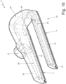
- Each assembly supports a sucking holding head 4 (better illustrated in Figures 8 , 9 , and 10 ) equipped with two sucking seats 5 that are parallel and simultaneously take two cigarette segments from a double forming beam of a cigarette packaging machine; according to a different embodiment not illustrated, each holding head 4 comprises a single sucking seat 5 taking just one cigarette segment at a time from a single forming beam of a cigarette packaging machine.
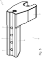
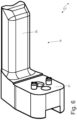
- the filter application machine 1 comprises a separation drum 6, which is assembled so that it can rotate, with continuous motion, around a rotation axis 7 and supports multiple holding heads 8 (illustrated in Figures 5 , 6 , and 7 ), each of which is equipped with a single sucking seat 9 designed to hold a corresponding filter.
- the filter application machine 1 comprises a staggering drum 10 or scaler (better illustrated in Figure 2 ), which is assembled so that it rotates, with continuous motion, around a rotation axis 11.
- the staggering drum 10 staggers two (or more) segments of cigarette filters initially placed side-by-side and with their heads circumferentially (tangentially) in contact with each other (via a circumferential movement of at least one filter segment) to arrange them at a certain circumferential distance from each other.
- the filter segments entering the staggering drum 10 are circumferentially aligned between them, while the filter segments exiting the staggering drum 10 are separated (staggered) circumferentially between them.
- the staggering drum 10 takes the filter segments from an entry station arranged at the cutting drum and feeds the circumferentially staggered filter segments to an outlet station arranged near a subsequent combining drum.
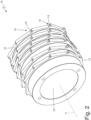
- the staggering drum 10 comprises a central body 12 (only partially illustrated in Figure 2 ), which is assembled so that it can rotate around the rotation axis 11 (i.e., it is connected so that it can rotate around a frame of the filter application machine 1), and multiple operating rings 13, which are fitted, one after the other, around the central body 12 to form a shell that surrounds the central body 12 (i.e., the operating rings 13 form a shell covering the central body 12).
- the operating rings 13 define sucking seats 14 that are designed to hold the cigarettes and are provided with respective suction holes 15 flowing out through the outer surface of the operating rings 13.
- the operating rings 13 are fitted (mounted) in a removable manner on the central body 12 and, thus, can be replaced (i.e., mounted and remounted) relatively quickly.
- each staggering drum 10 the corresponding central body 12 becomes a part of a standard machine totally disconnected from the smoking articles format (i.e., it is never replaced or adjusted during a format change), while the operating rings 13 alone are part of a format machine that must vary as a function of the smoking article format (i.e., they must be replaced during a format change).
- the operating machines 13 have a series of sucking seats 14 (each of which is designed to hold a cylindrical smoking article) provided with corresponding suction holes 15; in addition, and as illustrated in Figure 4 , the operating rings 13 comprise a series of tubular ducts 16, each originating from an input opening 17 arranged in the area of an inner wall of an operating ring 13 and ending in a respective suction hole 15 in the area of an outer wall of the operating ring 13.
- each tubular duct 16 connects a pneumatic distributor formed in the central body 12 to the suction holes 15.
- the tubular ducts 16 are formed inside the corresponding operating rings 13.
- valves adjusting the suction flow are formed inside the central body 12 and, thus, they always remain the same (and, so, in the same position) for all the formats, since the central body 12 is a part of a standard machine that is not replaced during a format change; obviously, the inlet openings 17 of the tubular ducts 16 formed in the operating rings 13 are positioned so that they can be optimally coupled with the corresponding openings formed in the central body 12.
- the staggering drum 10 of the filter application machine 1 circumferentially staggers the filter segments to a relatively limited degree; i.e., the circumferential movement of some filter segments in relation to other filter segments has a relatively limited stroke.
- a staggering drum of a combining machine producing combined filters circumferentially staggers the filter segments to a relatively high degree (if compared to the staggering drum 10 of the filter application machine 1); i.e., the circumferential staggering of some filter segments compared to other filter segments has a relatively limited stroke (if compared to the staggering drum 10 of the filter application machine 1).
- each holding head 8 comprising a sucking seat 9 provided with multiple suction holes 18, which are connected to a suction source, is illustrated.
- each holding head 8 comprises a support body 19 that is L-shaped and consists of a main element 20, in which the sucking seat 19 is formed, and a connection element 21 forming a right angle with the main element 20 and is connected to the separation drum 6.
- a tubular duct 22 is formed, which ends in the suction holes 18 and connects the suction holes 18 to a pneumatic distributor formed in the separation drum 6.
- each holding head 4 comprising two sucking seats 5, each of which is provided with multiple suction holes 23, which are connected to a suction source, is illustrated.
- each holding head 4 comprises a support body 24 that is U-shaped and comprises two, straight main elements 25 parallel to each other, in which the sucking seats 5 are formed, and a connection element 26 connecting the main elements 25 together.
- Each main element 25 has an attachment 27 that is fixed to the transfer drum 2.
- a tubular duct 28 is formed, which ends in the suction holes 23 and connects the suction holes 23 to a pneumatic distributor formed in the transfer drum 2.
- reference number 29 indicates, as a whole, a wrapping machine that is designed to produce a rigid cigarette pack with a hinged lid and functions with intermittent motion (i.e., motion that involves a cyclical alternation of motion and rest phases).
- the wrapping machine 29 comprises a forming unit A, in which groups of cigarettes are formed in succession; a wrapping unit B, in which, around each group of cigarettes, a corresponding wrapping sheet is wrapped to create an inner wrapping; and a wrapping unit C, in which, around each inner wrapping, a collar is wrapped and a blank for creating an outer container provided with a lid.
- the forming unit A of the cigarette groups comprises a hopper 30 provided with three outlet mouths for simultaneously feeding three cigarette groups to three corresponding pockets of a forming conveyor that supports multiple pockets.
- the wrapping unit B comprises a wrapping conveyor 31 designed to feed each cigarette group along a straight, horizontal wrapping path.
- the wrapping path extends through a feeding station S1, wherein each cigarette group is coupled to a corresponding wrapping sheet that is folded in a U around the cigarette group.
- the wrapping machine 29 comprises a feeding device 32 that cyclically feeds the wrapping sheets into the feeding station S1, i.e., it arranges each wrapping sheet in the feeding station S 1 so that the wrapping sheet is intercepted by a corresponding cigarette group that advances along the wrapping path.
- the wrapping machine 29 comprises a wrapping drum 33, which supports multiple pockets 34 (one of which is illustrated in Figure 16 ), each of which is designed to contain an inner wrapping and a collar, and is assembled so that it rotates (with intermittent motion, i.e., "in steps” ) around a horizontal, parallel rotation axis.
- Each pocket 34 of the wrapping drum 33 receives a collar at a feeding station S2, thus receiving an inner wrapping at a transfer station S3, subsequently it receives a blank at a feeding station S4, and transfers the inner wrapping, the collar, and the blank together at a transfer station S5.
- the wrapping machine 29 comprises a feeding device 35 that cyclically feeds the collars in the feeding station S2, i.e., arranges each collar opposite a pocket 34.
- the feeding device 35 separates the collars from a continuous band via a transverse cut; alternatively, the feeding device 35 could feed the collars from the hopper.
- the wrapping machine 29 comprises a feeding drum 36 that supports multiple sucking holding heads (not illustrated), each of which is designed to hold a corresponding blank, and is assembled so that it rotates (with intermittent motion, i.e., "in steps” ) around a horizontal rotation axis to feed each sucking holding head along a circular feeding path.
- the wrapping machine 29 comprises a wrapping drum 37 that is arranged downstream of the other wrapping drum 33, it supports multiple pockets, each of which is designed to contain an inner wrapper, a collar, and a blank (received from the wrapping drum 33 in the transfer station S5), and it is assembled so that it rotates (with intermittent motion, i.e., "in steps” ) around a horizontal rotation axis.
- the feeding device 35 comprises a movable support (not illustrated) that supports an individual sucking holding head 38 (illustrated in Figures 12-15 ) designed to hold a corresponding collar; in particular, the movable support cyclically moves the holding head 38 forward and backwards between a collar removal station and a collar delivery station.
- each sucking holding head 38 comprises a cylindrical connection body 39, which is connected to the feeding drum (not illustrated), and a tubular duct 40 projecting from a side surface of the connection body 39, it is perpendicular to a longitudinal axis of the connection body 39, and ends in two holding portions 41, each of which is provided with (at least) one suction hole 42.
- each tubular duct 40 branches out in two sections, each of which ends in a corresponding holding portion 41.
- the two holding portions 41 of the same tubular duct 40 are arranged at a certain distance from each other, to engage corresponding portions of a collar so as to grasp the collar safely and stably (i.e., without the collar being free to be deformed in an uncontrolled manner during the manipulation thereof).
- each tubular duct 40 only ends in an individual holding portion 41 or it ends in three-four holding portions 41 separated from each other.
- Each sucking holding head 38 comprises a flat reinforcement element 43, which is arranged alongside the tubular duct 40, is radially oriented (perpendicularly) in relation to the tubular duct 40, is connected to the tubular duct 40 at a middle line of the tubular duct 40, and projects from a side surface of the connection body 39.
- the reinforcement element 43 in each holding head 38, is initially arranged (i.e., in a part near the connection body 39) on both sides of the tubular duct 40 and is subsequently arranged (i.e., in a part that is distal to the connection body 39) on one side of the tubular duct 40 only.
- the reinforcement element 43 preferably has an outer edge 44 (visible in Figure 6 ), which is oriented perpendicularly to the reinforcement element 43 and confers greater stiffness against buckling.
- the tubular duct 40 does not only have the function of "suction conveyor" passively supported by the reinforcement element 43, but also performs an important structural function being a genuine reinforcement rib of the base element 25.
- the reinforcement element 43 alone would not be able to withstand the mechanical stresses to which it is subject in use, since only the reinforcement element 43 together with the tubular duct 40 (which substantially reinforces the reinforcement element 43) is able to withstand the mechanical stresses to which it is subject in use.
- the tubular duct 40 performs an important function and, thus, in use the tubular duct 40 supports a significant part of the mechanical stresses to which the holding head 38 is subject.
- the tubular duct 40 is (partially) able to support itself, i.e., it also has an important structural function and is not, therefore, only used as a "suction conveyor".
- each pocket 44 of the wrapping drum 11 comprises a rectangular peripheral frame 45 that is entirely solid and delimits a cavity arranged at the centre.
- the peripheral frame 45 is rectangular and extends in a ring around the cavity arranged at the centre.
- Each pocket 44 is a suction pocket and comprises multiple sucking holes 46, flowing out through an outer surface of the peripheral frame 45 and, in use, they have the function of holding a corresponding collar and blank inside the pocket 44.
- each pocket 44 comprises a series of tubular ducts 47 (illustrated in Figures 18 and 19 ) ending in the sucking holes 46 and extending inside the peripheral frame 45, i.e., they are formed inside the hollow peripheral frame 45, avoiding depositing the material at the tubular ducts 47.
- reference number 48 indicates, as a whole, a packaging machine for the production of smoking articles (such as cigarettes containing tobacco) or of parts of smoking articles (for example, filters for conventional cigarettes and for new-generation cigarettes).
- the packaging machine 48 comprises a preparation unit 49, in which a continuous cylinder 50 (worm) of filtering material (or tobacco) is produced in a known way, and a forming beam 51, in which a paper band 52 (or another container material) is wound around the continuous cylinder 49 in a tube fed by a feeding unit 52.
- the continuous cylinder 50 is fed at the inlet of the forming beam 51 above the paper band 52, which is successively folded along the forming beam 51 into a tube around the cylinder 50.
- the packaging machine 1 comprises a gumming device 54, which is arranged at a gumming station arranged at the start of the forming beam 51 in an area wherein the paper band 52 has not yet been folded in a tube around the cylinder 50. Before completely folding the paper band 52 in a tube, the gumming device 54 applies a continuous strip of glue to one edge of the paper band 52.
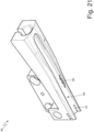
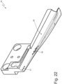
- an initial part 55 of the forming beam 51 is illustrated (identified in the jargon with the name "tongue” ) , which has, inside, a cylindrical passage channel 56 inside of which the continuous cylinder 50 slides, partially wound by the paper band 52.
- a series of blowing holes 57 opens (three on the left side and three on the right side) and another series of blowing holes 58 (nine on the left side and nine on the right side).
- tubular ducts are formed, which flow into the blowing holes 57 and other tubular ducts, which flow into the other blowing holes 58.
- each pneumatic component (holding head 4, holding head 8, operating ring 13, holding head 38, pocket 34, and initial part 55) is a single monolithic piece, it is composed of a single, indivisible body made all together and entirely seamlessly, and is manufactured using additive manufacturing.
- Each pneumatic component is made using additive manufacturing (also called 3D printing), i.e., using an industrial process that, beginning with a digital 3D model, creates the piece adding one layer over the other (some examples of technologies that can be used in additive manufacturing are stereolithography; fusion deposition modelling, also called FDM; selective laser sintering, also called SLS; or direct laser microfusion or DLM).
- additive manufacturing also called 3D printing
- FDM fusion deposition modelling
- SLS selective laser sintering
- DLM direct laser microfusion
- each pneumatic component (holding head 4, holding head 8, operating ring 13, holding head 38, pocket 34, initial part 55) is entirely made of plastic (plastic or resin), i.e., not of metal (basically to reduce the cost of production and the weight), since each pneumatic component in use is not subject to significant mechanical stresses.
- the plastic with which each pneumatic component is made could, potentially, be filled (reinforced) with carbon or glass to improve the structural characteristics (for example Nylon 12CF is a thermoplastic composite for carbon-filled 3D printing with excellent structural characteristics).
- each pneumatic component (holding head 4, holding head 8, operating ring 13, holding head 38, pocket 34, or initial part 55) is entirely made of metal (for example, steel or aluminium), which has greater resistance to wear.
- the use of additive manufacturing makes it possible to optimise the fluid dynamic efficiency of the corresponding tubular ducts 16, 22, 28, 40, 47 since the tubular ducts 16, 22, 28, 40, 47 may have irregular shapes (typically with curves that form an angle very different to 90° and/or with a variable cross section area) chosen to optimise the fluid dynamic efficiency (i.e., without taking into account in any way the construction and assembly issues that there would be if additive manufacturing were not used).
- the area of the cross-section may continuously vary (i.e., without forming "steps" ) in order to optimise the fluid dynamic efficiency.
- the use of additive manufacturing makes it possible to transfer the shape of the tubular ducts 16, 22, 28, 40, 47 calculated using a fluid dynamic numerical analysis, to all the pneumatic components (holding head 4, holding head 8, operating rings 13, holding head 38, pocket 34, initial part 55) described above, in order to balance air flows, minimising losses, distributing the up thrust forces of the product in the most efficient manner along the whole length of the holding section.
- the pneumatic components (holding head 4, holding head 8, operating ring 13, holding head 38, pocket 34, initial part 55) of the operating machine described above have a fluid dynamics that is optimised to minimise charge losses and, thus, maximise energy efficiency (i.e., the use of moderate power is enough to produce a suction or blowing and, thus, less energy is consumed).
- optimised fluid dynamics of the pneumatic components improves (i.e., makes more stable and secure) how materials and products are held, increasing the final quality of products and reducing the number of defective products to be thrown away.
- the production of the operating machine described above is especially simple and economical in that the pneumatic components (holding head 4, holding head 8, operating ring 13, holding head 38, pocket 34, initial part 55) of the operating machine described above may be manufactured quickly and inexpensively thanks to additive manufacturing.
Landscapes
- Chemical & Material Sciences (AREA)
- Engineering & Computer Science (AREA)
- Manufacturing & Machinery (AREA)
- Materials Engineering (AREA)
- Cigarettes, Filters, And Manufacturing Of Filters (AREA)
- Manufacturing Of Cigar And Cigarette Tobacco (AREA)
- Wrapping Of Specific Fragile Articles (AREA)
- Polishing Bodies And Polishing Tools (AREA)
- Percussive Tools And Related Accessories (AREA)
- Scissors And Nippers (AREA)
Abstract
Description
- This patent application claims priority from
Italian patent application no. 102020000029435 filed on December 2, 2020 - This invention relates to an operating machine for processing smoking articles, for example a wrapping machine for producing cigarette packets, a packing machine for producing cigarettes or cigarette filters, or a filter application machine for applying filters to cigarettes.
- An operating machine for processing smoking articles comprises numerous components assembled together.
- Some of these components are pneumatic, or they have, on their outer surface, holes through which (more frequently) suction is generated to hold an element being processed in contact with the outer surface of the component or through which (more rarely) a puff of compressed air is generated to pneumatically push on an element being processed.
- A pneumatic component generally comprises a series of holes made through the outer surface of the pneumatic component and a system of internal channels arranged at least partially inside a pneumatic component to distribute the sucking or the compressed air to the holes. Normally, and for simplicity of production, the channels (often formed from the solid using chip removal processing) have a straight progression with elbow curves (i.e., forming a 90° angle); in any case, these regular channel shapes, imposed by the necessity of manufacturing without excessive complications, is decisively challenging in terms of fluid dynamics, i.e. it entails the loss of significant charges leading to decidedly unfavourable energy efficiency (i.e. to produce relatively limited suction or blowing, a lot of power is needed and, thus, it is necessary to consume a significant amount of energy).
- The patent application
DE102009009829B4 describes a method for manufacturing a piece formed for a cigarette packaging machine; the formed piece comprises a base body on which printed parts with surfaces in contact with the materials being processed are made using a laser ray. - The purpose of this invention is to overcome the above-mentioned drawbacks, i.e., to provide an operating machine for processing smoking articles that is free of the drawbacks described above.
- This purpose is achieved with an operating machine for processing smoking articles in accordance with the attached claims.
- The claims describe preferred embodiments of this invention forming an integral part of this description.
- This invention will now be described with reference to the attached drawings that illustrate some non-limiting embodiments thereof, in which:
-
Figure 1 is a schematic, front view of a filter application machine; -
Figure 2 is a schematic perspective view of a staggering drum (scaler) of the filter application machine inFigure 1 ; -
Figure 3 is a perspective view of a series of operating rings of the staggering drum inFigure 2 ; -
Figure 4 is a cross-section view of an operating ring of the staggering drum inFigure 2 ; -
Figures 5 and6 are two different perspective views of a holding head of a separation drum of the filter application machine inFigure 1 ; -
Figure 7 is a longitudinal cross-section view of the holding head inFigures 5 and6 ; -
Figures 8 and9 are two different perspective views of a holding head of a conveyor drum of the filter application machine inFigure 1 ; -
Figure 10 is a perspective view of the holding head inFigures 8 and9 with the internal, pneumatic channels highlighted; -
Figure 11 is a schematic, perspective view of a wrapping machine; -
Figure 12 is a perspective view of a sucking holding head of the filter application machine inFigure 11 ; -
Figure 13 is an additional perspective view of the sucking holding head inFigure 12 ; -
Figure 14 is a plan view of the sucking holding head inFigure 12 ; -
Figure 15 is a cross-section view along the line XV-XV of the sucking holding head inFigure 12 ; -
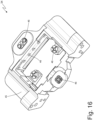
Figure 16 is a perspective view of a sucking pocket of a wrapping drum of the wrapping machine inFigure 11 ; -
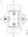
Figure 17 is a plan view of the sucking pocket inFigure 16 ; -
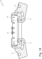
Figures 18 and19 are two cross-section views along the lines XVIII-XVIII and IXX-IXX of the sucking pocket inFigure 16 ; -
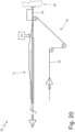
Figure 20 is a schematic view, with parts removed for clarity, of a packaging machine for the production of smoking articles or of parts for smoking articles; -
Figure 21 is a perspective view of an initial part of a forming beam of the packaging machine inFigure 20 ; and -
Figure 22 is a perspective view in cross-section of the initial part inFigure 21 . - With reference to
Figure 1 , thereference number 1 indicates, as a whole, a filter application machine for applying filters to cigarettes (i.e., an operating machine for processing smoking articles). - The
filter application machine 1 comprises multiple rotating conveyors, each of which is assembled so that it can rotate, with continuous motion, around a central rotation axis and supports, on the side, a series of sucking seats each of which is designed to hold at least one corresponding cigarette and/or at least one corresponding filter. - In particular, the
filter application machine 1 comprises atransfer drum 2, (called a "spider", in the jargon) which is assembled so that it can rotate, with continuous motion, around arotation axis 3 and supports multiple tools, each of which is mounted so that it rotates around thetransfer drum 2 to rotate around a respective rotation axis parallel to therotation axis 3 of thetransfer drum 2 so as to always remain horizontal and parallel to itself. Each assembly supports a sucking holding head 4 (better illustrated inFigures 8 ,9 , and10 ) equipped with two suckingseats 5 that are parallel and simultaneously take two cigarette segments from a double forming beam of a cigarette packaging machine; according to a different embodiment not illustrated, eachholding head 4 comprises a single suckingseat 5 taking just one cigarette segment at a time from a single forming beam of a cigarette packaging machine. - In addition, the
filter application machine 1 comprises aseparation drum 6, which is assembled so that it can rotate, with continuous motion, around a rotation axis 7 and supports multiple holding heads 8 (illustrated inFigures 5 ,6 , and7 ), each of which is equipped with a single suckingseat 9 designed to hold a corresponding filter. - Finally, the
filter application machine 1 comprises astaggering drum 10 or scaler (better illustrated inFigure 2 ), which is assembled so that it rotates, with continuous motion, around arotation axis 11. The staggeringdrum 10 staggers two (or more) segments of cigarette filters initially placed side-by-side and with their heads circumferentially (tangentially) in contact with each other (via a circumferential movement of at least one filter segment) to arrange them at a certain circumferential distance from each other. Thus, the filter segments entering thestaggering drum 10 are circumferentially aligned between them, while the filter segments exiting thestaggering drum 10 are separated (staggered) circumferentially between them. In particular, thestaggering drum 10 takes the filter segments from an entry station arranged at the cutting drum and feeds the circumferentially staggered filter segments to an outlet station arranged near a subsequent combining drum. - According to what is illustrated in
Figures 2 ,3 , and4 , thestaggering drum 10 comprises a central body 12 (only partially illustrated inFigure 2 ), which is assembled so that it can rotate around the rotation axis 11 (i.e., it is connected so that it can rotate around a frame of the filter application machine 1), andmultiple operating rings 13, which are fitted, one after the other, around thecentral body 12 to form a shell that surrounds the central body 12 (i.e., theoperating rings 13 form a shell covering the central body 12). The operatingrings 13 define suckingseats 14 that are designed to hold the cigarettes and are provided withrespective suction holes 15 flowing out through the outer surface of theoperating rings 13. Theoperating rings 13 are fitted (mounted) in a removable manner on thecentral body 12 and, thus, can be replaced (i.e., mounted and remounted) relatively quickly. - If there is a format change, i.e. when the
filter application machine 1 needs to process cigarettes of different sizes (in particular, with different diameters), it is necessary to modify the shape of the sucking seats 14 (which must reproduce, in negative, the shape of the cigarettes); this operation requires the replacement of just the operating rings 13 (in which the suckingseats 14 are formed) and does not require the replacement of thecentral body 12 and, thus, it is clearly faster and easier (it is significantly easier to disassemble/assemble just theoperating rings 13 rather than the whole staggering drum 10). In addition, a set of spare parts for a new cigarette format is clearly more economical and compact (theoperating rings 13 alone require much less material than the whole staggering drum 10). In other words, in eachstaggering drum 10, the correspondingcentral body 12 becomes a part of a standard machine totally disconnected from the smoking articles format (i.e., it is never replaced or adjusted during a format change), while theoperating rings 13 alone are part of a format machine that must vary as a function of the smoking article format (i.e., they must be replaced during a format change). - The
operating machines 13 have a series of sucking seats 14 (each of which is designed to hold a cylindrical smoking article) provided withcorresponding suction holes 15; in addition, and as illustrated inFigure 4 , theoperating rings 13 comprise a series oftubular ducts 16, each originating from aninput opening 17 arranged in the area of an inner wall of anoperating ring 13 and ending in arespective suction hole 15 in the area of an outer wall of theoperating ring 13. In other words, eachtubular duct 16 connects a pneumatic distributor formed in thecentral body 12 to thesuction holes 15. Thetubular ducts 16 are formed inside thecorresponding operating rings 13. - It is important to note that the valves adjusting the suction flow are formed inside the
central body 12 and, thus, they always remain the same (and, so, in the same position) for all the formats, since thecentral body 12 is a part of a standard machine that is not replaced during a format change; obviously, theinlet openings 17 of thetubular ducts 16 formed in theoperating rings 13 are positioned so that they can be optimally coupled with the corresponding openings formed in thecentral body 12. - The
staggering drum 10 of thefilter application machine 1 circumferentially staggers the filter segments to a relatively limited degree; i.e., the circumferential movement of some filter segments in relation to other filter segments has a relatively limited stroke. In contrast, a staggering drum of a combining machine producing combined filters circumferentially staggers the filter segments to a relatively high degree (if compared to thestaggering drum 10 of the filter application machine 1); i.e., the circumferential staggering of some filter segments compared to other filter segments has a relatively limited stroke (if compared to thestaggering drum 10 of the filter application machine 1). - In
Figures 5 ,6 , and7 , aholding head 8 comprising a suckingseat 9 provided withmultiple suction holes 18, which are connected to a suction source, is illustrated. In particular, eachholding head 8 comprises asupport body 19 that is L-shaped and consists of amain element 20, in which the suckingseat 19 is formed, and aconnection element 21 forming a right angle with themain element 20 and is connected to theseparation drum 6. According to what is illustrated inFigure 7 , inside thesupport body 19 of eachholding head 8, atubular duct 22 is formed, which ends in thesuction holes 18 and connects thesuction holes 18 to a pneumatic distributor formed in theseparation drum 6. - In
Figures 8 ,9 , and10 , aholding head 4 comprising two suckingseats 5, each of which is provided withmultiple suction holes 23, which are connected to a suction source, is illustrated. In particular, eachholding head 4 comprises asupport body 24 that is U-shaped and comprises two, straightmain elements 25 parallel to each other, in which the suckingseats 5 are formed, and aconnection element 26 connecting themain elements 25 together. Eachmain element 25 has anattachment 27 that is fixed to thetransfer drum 2. According to what is illustrated inFigure 10 , inside thesupport body 24 of eachholding head 4, atubular duct 28 is formed, which ends in thesuction holes 23 and connects thesuction holes 23 to a pneumatic distributor formed in thetransfer drum 2. - With reference to
Figure 11 ,reference number 29 indicates, as a whole, a wrapping machine that is designed to produce a rigid cigarette pack with a hinged lid and functions with intermittent motion (i.e., motion that involves a cyclical alternation of motion and rest phases). - The wrapping
machine 29 comprises a forming unit A, in which groups of cigarettes are formed in succession; a wrapping unit B, in which, around each group of cigarettes, a corresponding wrapping sheet is wrapped to create an inner wrapping; and a wrapping unit C, in which, around each inner wrapping, a collar is wrapped and a blank for creating an outer container provided with a lid. - The forming unit A of the cigarette groups comprises a
hopper 30 provided with three outlet mouths for simultaneously feeding three cigarette groups to three corresponding pockets of a forming conveyor that supports multiple pockets. - The wrapping unit B comprises a wrapping
conveyor 31 designed to feed each cigarette group along a straight, horizontal wrapping path. In particular, the wrapping path extends through a feeding station S1, wherein each cigarette group is coupled to a corresponding wrapping sheet that is folded in a U around the cigarette group. - The wrapping
machine 29 comprises afeeding device 32 that cyclically feeds the wrapping sheets into the feeding station S1, i.e., it arranges each wrapping sheet in thefeeding station S 1 so that the wrapping sheet is intercepted by a corresponding cigarette group that advances along the wrapping path. - The wrapping
machine 29 comprises a wrappingdrum 33, which supports multiple pockets 34 (one of which is illustrated inFigure 16 ), each of which is designed to contain an inner wrapping and a collar, and is assembled so that it rotates (with intermittent motion, i.e., "in steps") around a horizontal, parallel rotation axis. Eachpocket 34 of the wrappingdrum 33 receives a collar at a feeding station S2, thus receiving an inner wrapping at a transfer station S3, subsequently it receives a blank at a feeding station S4, and transfers the inner wrapping, the collar, and the blank together at a transfer station S5. - The wrapping
machine 29 comprises afeeding device 35 that cyclically feeds the collars in the feeding station S2, i.e., arranges each collar opposite apocket 34. In the embodiment illustrated inFigure 1 , thefeeding device 35 separates the collars from a continuous band via a transverse cut; alternatively, thefeeding device 35 could feed the collars from the hopper. - The wrapping
machine 29 comprises a feedingdrum 36 that supports multiple sucking holding heads (not illustrated), each of which is designed to hold a corresponding blank, and is assembled so that it rotates (with intermittent motion, i.e., "in steps") around a horizontal rotation axis to feed each sucking holding head along a circular feeding path. - Finally, the wrapping
machine 29 comprises a wrappingdrum 37 that is arranged downstream of the other wrappingdrum 33, it supports multiple pockets, each of which is designed to contain an inner wrapper, a collar, and a blank (received from the wrappingdrum 33 in the transfer station S5), and it is assembled so that it rotates (with intermittent motion, i.e., "in steps") around a horizontal rotation axis. - The
feeding device 35 comprises a movable support (not illustrated) that supports an individual sucking holding head 38 (illustrated inFigures 12-15 ) designed to hold a corresponding collar; in particular, the movable support cyclically moves the holdinghead 38 forward and backwards between a collar removal station and a collar delivery station. According to what is illustrated inFigures 12-15 , each sucking holdinghead 38 comprises acylindrical connection body 39, which is connected to the feeding drum (not illustrated), and atubular duct 40 projecting from a side surface of theconnection body 39, it is perpendicular to a longitudinal axis of theconnection body 39, and ends in two holdingportions 41, each of which is provided with (at least) one suction hole 42. In other words, in the final part, eachtubular duct 40 branches out in two sections, each of which ends in a corresponding holdingportion 41. The two holdingportions 41 of the sametubular duct 40 are arranged at a certain distance from each other, to engage corresponding portions of a collar so as to grasp the collar safely and stably (i.e., without the collar being free to be deformed in an uncontrolled manner during the manipulation thereof). According to a different embodiment not illustrated, eachtubular duct 40 only ends in anindividual holding portion 41 or it ends in three-fourholding portions 41 separated from each other. - Each sucking holding
head 38 comprises aflat reinforcement element 43, which is arranged alongside thetubular duct 40, is radially oriented (perpendicularly) in relation to thetubular duct 40, is connected to thetubular duct 40 at a middle line of thetubular duct 40, and projects from a side surface of theconnection body 39. According to what is illustrated in the attached figures, in each holdinghead 38, thereinforcement element 43 is initially arranged (i.e., in a part near the connection body 39) on both sides of thetubular duct 40 and is subsequently arranged (i.e., in a part that is distal to the connection body 39) on one side of thetubular duct 40 only. In each holdinghead 38, thereinforcement element 43 preferably has an outer edge 44 (visible inFigure 6 ), which is oriented perpendicularly to thereinforcement element 43 and confers greater stiffness against buckling. - It is important to underline how the
tubular duct 40 does not only have the function of "suction conveyor" passively supported by thereinforcement element 43, but also performs an important structural function being a genuine reinforcement rib of thebase element 25. In other words, thereinforcement element 43 alone would not be able to withstand the mechanical stresses to which it is subject in use, since only thereinforcement element 43 together with the tubular duct 40 (which substantially reinforces the reinforcement element 43) is able to withstand the mechanical stresses to which it is subject in use. In other words, in the mechanical sizing of a holdinghead 38, thetubular duct 40 performs an important function and, thus, in use thetubular duct 40 supports a significant part of the mechanical stresses to which the holdinghead 38 is subject. As a result, thetubular duct 40 is (partially) able to support itself, i.e., it also has an important structural function and is not, therefore, only used as a "suction conveyor". - According to what is illustrated in
Figures 16-19 , eachpocket 44 of the wrappingdrum 11 comprises a rectangularperipheral frame 45 that is entirely solid and delimits a cavity arranged at the centre. In other words, theperipheral frame 45 is rectangular and extends in a ring around the cavity arranged at the centre. Eachpocket 44 is a suction pocket and comprises multiple suckingholes 46, flowing out through an outer surface of theperipheral frame 45 and, in use, they have the function of holding a corresponding collar and blank inside thepocket 44. In addition, eachpocket 44 comprises a series of tubular ducts 47 (illustrated inFigures 18 and19 ) ending in the suckingholes 46 and extending inside theperipheral frame 45, i.e., they are formed inside the hollowperipheral frame 45, avoiding depositing the material at thetubular ducts 47. - In
Figure 20 ,reference number 48 indicates, as a whole, a packaging machine for the production of smoking articles (such as cigarettes containing tobacco) or of parts of smoking articles (for example, filters for conventional cigarettes and for new-generation cigarettes). Thepackaging machine 48 comprises apreparation unit 49, in which a continuous cylinder 50 (worm) of filtering material (or tobacco) is produced in a known way, and a formingbeam 51, in which a paper band 52 (or another container material) is wound around thecontinuous cylinder 49 in a tube fed by afeeding unit 52. In other words, thecontinuous cylinder 50 is fed at the inlet of the formingbeam 51 above thepaper band 52, which is successively folded along the formingbeam 51 into a tube around thecylinder 50. - The
packaging machine 1 comprises a gummingdevice 54, which is arranged at a gumming station arranged at the start of the formingbeam 51 in an area wherein thepaper band 52 has not yet been folded in a tube around thecylinder 50. Before completely folding thepaper band 52 in a tube, the gummingdevice 54 applies a continuous strip of glue to one edge of thepaper band 52. - In
Figures 21 and22 , aninitial part 55 of the formingbeam 51 is illustrated (identified in the jargon with the name "tongue"), which has, inside, acylindrical passage channel 56 inside of which thecontinuous cylinder 50 slides, partially wound by thepaper band 52. Along one surface of the passage channel 56 a series of blowingholes 57 opens (three on the left side and three on the right side) and another series of blowing holes 58 (nine on the left side and nine on the right side). Inside theinitial part 55 of the formingbeam 51, tubular ducts are formed, which flow into the blowing holes 57 and other tubular ducts, which flow into the other blowing holes 58. - The holding heads 4, the holding heads 8, and the operating rings 13 of the
filter application machine 1, the holding heads 38 and thepockets 34 of the wrappingmachine 29, and theinitial part 55 of the formingbeam 51 of thepackaging machine 48 are examples of pneumatic components of an operating machine for processing smoking articles that are advantageously produced using additive manufacturing. In other words, each pneumatic component (holdinghead 4, holdinghead 8, operatingring 13, holdinghead 38,pocket 34, and initial part 55) is a single monolithic piece, it is composed of a single, indivisible body made all together and entirely seamlessly, and is manufactured using additive manufacturing. - Each pneumatic component is made using additive manufacturing (also called 3D printing), i.e., using an industrial process that, beginning with a digital 3D model, creates the piece adding one layer over the other (some examples of technologies that can be used in additive manufacturing are stereolithography; fusion deposition modelling, also called FDM; selective laser sintering, also called SLS; or direct laser microfusion or DLM).
- According to one possible embodiment, each pneumatic component (holding
head 4, holdinghead 8, operatingring 13, holdinghead 38,pocket 34, initial part 55) is entirely made of plastic (plastic or resin), i.e., not of metal (basically to reduce the cost of production and the weight), since each pneumatic component in use is not subject to significant mechanical stresses. The plastic with which each pneumatic component is made, could, potentially, be filled (reinforced) with carbon or glass to improve the structural characteristics (for example Nylon 12CF is a thermoplastic composite for carbon-filled 3D printing with excellent structural characteristics). - According to a different embodiment, each pneumatic component (holding
head 4, holdinghead 8, operatingring 13, holdinghead 38,pocket 34, or initial part 55) is entirely made of metal (for example, steel or aluminium), which has greater resistance to wear. - In all the pneumatic components (holding
head 4, holdinghead 8, operatingring 13, holdinghead 38,pocket 34, initial part 55) described above, the use of additive manufacturing (which makes each component a single undivided and indivisible body) makes it possible to optimise the fluid dynamic efficiency of the correspondingtubular ducts tubular ducts - In other words, the use of additive manufacturing makes it possible to transfer the shape of the
tubular ducts head 4, holdinghead 8, operating rings 13, holdinghead 38,pocket 34, initial part 55) described above, in order to balance air flows, minimising losses, distributing the up thrust forces of the product in the most efficient manner along the whole length of the holding section. - In addition, the use of additive manufacturing (which makes each pneumatic component a single undivided and indivisible body) makes it possible to create
tubular ducts tubular ducts - In the first place, the pneumatic components (holding
head 4, holdinghead 8, operatingring 13, holdinghead 38,pocket 34, initial part 55) of the operating machine described above have a fluid dynamics that is optimised to minimise charge losses and, thus, maximise energy efficiency (i.e., the use of moderate power is enough to produce a suction or blowing and, thus, less energy is consumed). - In addition, the optimised fluid dynamics of the pneumatic components (holding
head 4, holdinghead 8, operatingring 13, holdinghead 38,pocket 34, initial part 55) of the operating machine described above improves (i.e., makes more stable and secure) how materials and products are held, increasing the final quality of products and reducing the number of defective products to be thrown away. - Finally, the production of the operating machine described above is especially simple and economical in that the pneumatic components (holding
head 4, holdinghead 8, operatingring 13, holdinghead 38,pocket 34, initial part 55) of the operating machine described above may be manufactured quickly and inexpensively thanks to additive manufacturing.
Claims (15)
- An operating machine (1; 29; 48) to process smoking articles and comprising at least one pneumatic component having a plurality of holes (15; 18; 23; 42; 46; 57; 58), which are obtained through an outer surface and can be connected to a pneumatic system, and at least one tubular duct (16; 22; 28; 40; 47), which ends in the holes (15; 18; 23; 42; 46; 57; 58);wherein the pneumatic component is one single monolithic piece, consists of one single indivisible body manufactured as a whole seamlessly and is manufactured by means of additive manufacturing; andwherein the tubular duct (16; 22; 28; 40; 47) has a non-straight geometry, which optimizes fluid-dynamic efficiency.
- The operating machine (1; 29; 48) according to claim 1, wherein the tubular duct (16; 22; 28; 40; 47) is obtained from the solid part inside the pneumatic component.
- The operating machine (1; 29; 48) according to claim 1 or 2, wherein the tubular duct (16; 22; 28; 40; 47) has curves forming an angle other than 90° and/or has a variable cross section area.
- The operating machine (1; 29; 48) according to claim 1, 2 or 3, wherein the pneumatic component is an operating ring (13) of a staggering drum (10).
- The operating machine (1; 29; 48) according to claim 4, wherein the staggering drum (10) comprises:a central body (12), which can rotate around a rotation axis (11); anda plurality of operating rings (13), which are fitted, in a removable manner and one following the other, around the central body (12) so as to form a shell surrounding the central body (12) and define sucking seats (14), which are designed to hold smoking articles and are provided with respective suction holes (15), which lead through the outer surface of the operating rings (13).
- The operating machine (1; 29; 48) according to claim 5, wherein the operating rings (13) comprise a series of tubular ducts (16), each originating from an input opening (17) arranged in the area of an inner wall of an operating ring (13) and ending in a respective suction hole (15) in the area of an outer wall of the operating ring (13).
- The operating machine (1; 29; 48) according to claim 1, 2 or 3, wherein the pneumatic component is a holding head (4; 8), which is provided with at least one sucking seat (5; 9) designed to hold a smoking article.
- The operating machine (1; 29; 1) according to claim 1, 2 or 3, wherein the pneumatic component is a sucking holding head (38), which is designed to hold, through suction, a wrapping sheet, in particular a collar.
- The operating machine (1; 29; 48) according to claim 8, wherein the sucking holding head (38) comprises a connection body (39) with a cylindrical shape and a tubular duct (40), which projects from a side surface of the connection body (39), is perpendicular to a longitudinal axis of the connection body (39) and ends in at least one holding portion (41) provided with a suction hole (42).
- The operating machine (1; 29; 48) according to claim 9, wherein the sucking holding head (38) comprises a flat reinforcement element (43), which is arranged besides the tubular duct (40), is connected to the tubular duct (40) in the area of a middle line of the tubular duct (40) and projects from a side surface of the connection body (39).
- The operating machine (1; 29; 48) according to claim 10, wherein the reinforcement element (43) has an outer edge (44), which is oriented perpendicularly to the reinforcement element (43).
- The operating machine (1; 29; 48) according to claim 1, 2 or 3, wherein the pneumatic component is a pocket (34) of a wrapping drum (33).
- The operating machine (1; 29; 48) according to claim 12, wherein the pocket (34) comprises a peripheral frame (45) with a rectangular shape, which delimits a cavity arranged at the centre.
- The operating machine (1; 29; 48) according to claim 1, 2 or 3, wherein the pneumatic component is an initial part (55) of a forming beam (51), which wraps a paper band (52) in a tubular manner, preferably around a continuous cylinder (50) of filtering material or of tobacco.
- A method for the production of a pneumatic component of an operating machine (1; 29; 48) to process smoking articles;wherein the pneumatic component has a plurality of holes (15; 18; 23; 42; 46; 57; 58), which are obtained through an outer surface and can be connected to a pneumatic system, and at least one tubular duct (16; 22; 28; 40; 47), which ends in the holes (15; 18; 23; 42; 46; 57; 58);wherein the pneumatic component is one single monolithic piece, consists of one single indivisible body manufactured as a whole seamlessly and is manufactured by means of additive manufacturing; andwherein the tubular duct (16; 22; 28; 40; 47) has a non-straight geometry, which optimizes fluid-dynamic efficiency.
Applications Claiming Priority (3)
| Application Number | Priority Date | Filing Date | Title |
|---|---|---|---|
| IT102020000029435A IT202000029435A1 (en) | 2020-12-02 | 2020-12-02 | OPERATING MACHINE FOR PROCESSING TOUGH ITEMS WITH A PNEUMATIC COMPONENT MADE BY ADDITIVE MANUFACTURING |
| PCT/IB2021/061248 WO2022118250A1 (en) | 2020-12-02 | 2021-12-02 | Operating machine to processing smoking articles with a pneumatic component made using additive manufacturing |
| EP21834890.2A EP4255227B1 (en) | 2020-12-02 | 2021-12-02 | Operating machine for processing smoking articles with a pneumatic component made using additive manufacturing |
Related Parent Applications (2)
| Application Number | Title | Priority Date | Filing Date |
|---|---|---|---|
| EP21834890.2A Division-Into EP4255227B1 (en) | 2020-12-02 | 2021-12-02 | Operating machine for processing smoking articles with a pneumatic component made using additive manufacturing |
| EP21834890.2A Division EP4255227B1 (en) | 2020-12-02 | 2021-12-02 | Operating machine for processing smoking articles with a pneumatic component made using additive manufacturing |
Publications (2)
| Publication Number | Publication Date |
|---|---|
| EP4327669A2 true EP4327669A2 (en) | 2024-02-28 |
| EP4327669A3 EP4327669A3 (en) | 2024-06-12 |
Family
ID=74669299
Family Applications (3)
| Application Number | Title | Priority Date | Filing Date |
|---|---|---|---|
| EP24151100.5A Active EP4328027B1 (en) | 2020-12-02 | 2021-12-02 | Operating machine for processing smoking articles with a pneumatic component made using additive manufacturing |
| EP24151107.0A Pending EP4327669A3 (en) | 2020-12-02 | 2021-12-02 | Operating machine for processing smoking articles with a pneumatic component made using additive manufacturing |
| EP21834890.2A Active EP4255227B1 (en) | 2020-12-02 | 2021-12-02 | Operating machine for processing smoking articles with a pneumatic component made using additive manufacturing |
Family Applications Before (1)
| Application Number | Title | Priority Date | Filing Date |
|---|---|---|---|
| EP24151100.5A Active EP4328027B1 (en) | 2020-12-02 | 2021-12-02 | Operating machine for processing smoking articles with a pneumatic component made using additive manufacturing |
Family Applications After (1)
| Application Number | Title | Priority Date | Filing Date |
|---|---|---|---|
| EP21834890.2A Active EP4255227B1 (en) | 2020-12-02 | 2021-12-02 | Operating machine for processing smoking articles with a pneumatic component made using additive manufacturing |
Country Status (4)
| Country | Link |
|---|---|
| EP (3) | EP4328027B1 (en) |
| IT (1) | IT202000029435A1 (en) |
| PL (2) | PL4328027T3 (en) |
| WO (1) | WO2022118250A1 (en) |
Families Citing this family (1)
| Publication number | Priority date | Publication date | Assignee | Title |
|---|---|---|---|---|
| EP4683528A1 (en) * | 2023-03-22 | 2026-01-28 | British American Tobacco South Africa (Pty) Ltd. | A drum for a tobacco industry product assembly machine |
Citations (1)
| Publication number | Priority date | Publication date | Assignee | Title |
|---|---|---|---|---|
| DE102009009829B4 (en) | 2009-02-18 | 2011-09-15 | Hauni Maschinenbau Ag | Process for the production of format parts for extrusion machines of the tobacco processing industry, format part and format device with format part |
Family Cites Families (21)
| Publication number | Priority date | Publication date | Assignee | Title |
|---|---|---|---|---|
| BE873317A (en) | 1978-01-23 | 1979-05-02 | Wiggins Teape Group Ltd | MEANS FOR DISPLACING A CURRENT OF ROD-SHAPED ELEMENTS |
| IT1102986B (en) | 1978-01-31 | 1985-10-14 | Cir S Pa Divisione Sasib Bolog | UNI FORME FEEDING DEVICE FOR ROUND ASTIFORM OBJECTS IN PARTICULAR MULTIPLE FILTERS FOR CIGARETTES |
| IT1257862B (en) | 1992-07-22 | 1996-02-13 | Gd Spa | Method for making cigarettes with filter |
| DE10214381B4 (en) | 2002-03-30 | 2005-02-24 | Hugo Beck Gmbh + Co. Kg Verpackungs-Maschinenbau | Device for unstacking leaves from a bottom of a stack |
| NL1021333C2 (en) | 2002-08-27 | 2004-03-01 | Pmb Uva Group B V | Apparatus and method for forming a cigar. |
| ITBO20030683A1 (en) | 2003-11-17 | 2005-05-18 | Gd Spa | DRUM CENTERER FOR FILTER MACHINES |
| DE102005011543A1 (en) | 2005-03-10 | 2006-09-14 | Hauni Maschinenbau Ag | Sliding / cutting drum |
| DE102005027554B4 (en) | 2005-06-14 | 2007-11-22 | Hauni Maschinenbau Ag | Conveyor drum of the tobacco processing industry with lever segments |
| IT1394491B1 (en) | 2009-07-01 | 2012-07-05 | Gd Spa | METHOD AND EQUIPMENT TO FORM AND APPLY FOLDED SHEETS |
| ITBO20110158A1 (en) | 2011-03-28 | 2012-09-29 | Gd Spa | TRANSFER OR ACCOMPANIMENT DRUM FOR FILTER OR CIGARETTE CUTTERS WITH OPERATIONAL HEADS CARRIED BY RADIAL ARMS. |
| ITBO20120155A1 (en) | 2012-03-22 | 2013-09-23 | Gd Spa | TRANSFER DEVICE FOR FILTERS OR CIGARETTES. |
| GB2505514A (en) | 2012-09-04 | 2014-03-05 | British American Tobacco Co | An apparatus and a method for manufacturing a smoking article |
| DE102012216048A1 (en) | 2012-09-11 | 2014-03-13 | Hauni Maschinenbau Ag | Conveying drum for conveying rod-shaped articles e.g. filter cigarettes to filter setting machine in tobacco processing industry, has grooved disc rotating structure in which grooves are formed for receiving rod-shaped articles |
| EP3231300B1 (en) | 2015-03-12 | 2020-11-04 | Japan Tobacco, Inc. | Method for manufacturing filtered cigarette |
| DE102015006512A1 (en) | 2015-05-26 | 2016-12-01 | Focke & Co. (Gmbh & Co. Kg) | Method of manufacturing spare parts for packaging machines |
| BR112017027800B1 (en) * | 2015-07-21 | 2022-08-09 | Philip Morris Products S.A. | PRODUCTION METHOD OF A TOBACCO CUTTING FILLING |
| CN108136499B (en) | 2015-10-02 | 2021-01-12 | 阿斯科公司 | Manifold and valve housing assembly for a manifold stack made by an additive manufacturing process |
| DE102016109740A1 (en) | 2016-05-26 | 2017-11-30 | Hauni Maschinenbau Gmbh | Insertion device and strand machine of the tobacco processing industry |
| DE102016113146B4 (en) | 2016-07-15 | 2022-03-03 | Murtfeldt Additive Solutions GmbH | Vacuum gripping device with gripping block |
| DE202016105825U1 (en) | 2016-10-18 | 2018-01-22 | Krones Ag | Labeling unit for applying form labels to containers |
| IT201900005946A1 (en) | 2019-04-17 | 2020-10-17 | Gd Spa | Wrapping unit and method for folding a sheet of wrapping around a group of smoking items. |
-
2020
- 2020-12-02 IT IT102020000029435A patent/IT202000029435A1/en unknown
-
2021
- 2021-12-02 WO PCT/IB2021/061248 patent/WO2022118250A1/en not_active Ceased
- 2021-12-02 PL PL24151100.5T patent/PL4328027T3/en unknown
- 2021-12-02 EP EP24151100.5A patent/EP4328027B1/en active Active
- 2021-12-02 PL PL21834890.2T patent/PL4255227T3/en unknown
- 2021-12-02 EP EP24151107.0A patent/EP4327669A3/en active Pending
- 2021-12-02 EP EP21834890.2A patent/EP4255227B1/en active Active
Patent Citations (1)
| Publication number | Priority date | Publication date | Assignee | Title |
|---|---|---|---|---|
| DE102009009829B4 (en) | 2009-02-18 | 2011-09-15 | Hauni Maschinenbau Ag | Process for the production of format parts for extrusion machines of the tobacco processing industry, format part and format device with format part |
Also Published As
| Publication number | Publication date |
|---|---|
| WO2022118250A8 (en) | 2023-01-05 |
| PL4255227T3 (en) | 2024-08-05 |
| EP4328027B1 (en) | 2025-07-16 |
| EP4328027A3 (en) | 2024-06-05 |
| PL4328027T3 (en) | 2025-10-06 |
| WO2022118250A1 (en) | 2022-06-09 |
| IT202000029435A1 (en) | 2022-06-02 |
| EP4255227B1 (en) | 2024-05-22 |
| EP4328027A2 (en) | 2024-02-28 |
| EP4255227A1 (en) | 2023-10-11 |
| EP4327669A3 (en) | 2024-06-12 |
Similar Documents
| Publication | Publication Date | Title |
|---|---|---|
| JP4630548B2 (en) | Apparatus and trough drum for organizing groups of filter segments to produce multi-segment filters for the tobacco processing industry | |
| JP5512540B2 (en) | Various embodiments for an apparatus, system, and method for producing a coaxial core tobacco rod making machine having an air carrier | |
| CN101081647A (en) | Packing method and machine for producing packets of cigarettes | |
| JP2005502376A5 (en) | ||
| EP4255227B1 (en) | Operating machine for processing smoking articles with a pneumatic component made using additive manufacturing | |
| JPS58111675A (en) | Method and apparatus for producing synthetic filter rod | |
| JP5180456B2 (en) | Method and machine for packaging a product into at least one sheet of packaging material | |
| EP3222532B2 (en) | Orientation unit and method for causing a change in orientation of a parallelepiped-shaped article in a packing machine | |
| CN105946288A (en) | Multifunctional automatic bag making production line for multiwall paper bag, paper-plastic bag and woven bag | |
| JP2930334B2 (en) | Cigarette packaging machine | |
| EP3808192A1 (en) | A machine for manufacturing filter rods | |
| JP2024528018A (en) | Method and device for manufacturing filter rods for the tobacco industry | |
| EP3639680B1 (en) | Production line and method for the production of rod-shaped articles of the tobacco industry | |
| JP2007099508A (en) | Transfer method and unit for product in packing device operating intermittently | |
| CN116249460A (en) | Device for producing multi-segment rod-shaped articles | |
| WO2022153182A1 (en) | Telescopic paper straw assembling apparatus and system | |
| CN103054179A (en) | Composite filter production module | |
| EP4255814A1 (en) | Operating machine to process smoking articles with a component made by additive manufacturing | |
| EP1746029A1 (en) | Method and device for wrapping articles | |
| EP3944774B1 (en) | Feeding unit for feeding beads and apparatus for manufactoring rods | |
| EP4444117A1 (en) | Method and system of manufacturing multisegment articles | |
| ITBO20110397A1 (en) | METHOD AND MACHINE FOR CIGAR PRODUCTION | |
| ITBO20110393A1 (en) | METHOD AND MACHINE FOR CIGAR PRODUCTION | |
| ITBO20110394A1 (en) | METHOD AND MACHINE FOR CIGAR PRODUCTION | |
| ITBO20110387A1 (en) | MACHINE FOR CIGAR PRODUCTION |
Legal Events
| Date | Code | Title | Description |
|---|---|---|---|
| PUAI | Public reference made under article 153(3) epc to a published international application that has entered the european phase |
Free format text: ORIGINAL CODE: 0009012 |
|
| STAA | Information on the status of an ep patent application or granted ep patent |
Free format text: STATUS: THE APPLICATION HAS BEEN PUBLISHED |
|
| AC | Divisional application: reference to earlier application |
Ref document number: 4255227 Country of ref document: EP Kind code of ref document: P |
|
| AK | Designated contracting states |
Kind code of ref document: A2 Designated state(s): AL AT BE BG CH CY CZ DE DK EE ES FI FR GB GR HR HU IE IS IT LI LT LU LV MC MK MT NL NO PL PT RO RS SE SI SK SM TR |
|
| PUAL | Search report despatched |
Free format text: ORIGINAL CODE: 0009013 |
|
| AK | Designated contracting states |
Kind code of ref document: A3 Designated state(s): AL AT BE BG CH CY CZ DE DK EE ES FI FR GB GR HR HU IE IS IT LI LT LU LV MC MK MT NL NO PL PT RO RS SE SI SK SM TR |
|
| RIC1 | Information provided on ipc code assigned before grant |
Ipc: B33Y 80/00 20150101ALI20240503BHEP Ipc: A24C 5/18 20060101ALI20240503BHEP Ipc: A24C 5/47 20060101ALI20240503BHEP Ipc: A24C 5/32 20060101AFI20240503BHEP |
|
| STAA | Information on the status of an ep patent application or granted ep patent |
Free format text: STATUS: REQUEST FOR EXAMINATION WAS MADE |
|
| 17P | Request for examination filed |
Effective date: 20241210 |