EP4325326A1 - Rocking handle protective cover and remote control - Google Patents
Rocking handle protective cover and remote control Download PDFInfo
- Publication number
- EP4325326A1 EP4325326A1 EP22787384.1A EP22787384A EP4325326A1 EP 4325326 A1 EP4325326 A1 EP 4325326A1 EP 22787384 A EP22787384 A EP 22787384A EP 4325326 A1 EP4325326 A1 EP 4325326A1
- Authority
- EP
- European Patent Office
- Prior art keywords
- control stick
- elastic member
- protective cover
- accommodation groove
- remote controller
- Prior art date
- Legal status (The legal status is an assumption and is not a legal conclusion. Google has not performed a legal analysis and makes no representation as to the accuracy of the status listed.)
- Pending
Links
Images



Classifications
-
- G—PHYSICS
- G05—CONTROLLING; REGULATING
- G05G—CONTROL DEVICES OR SYSTEMS INSOFAR AS CHARACTERISED BY MECHANICAL FEATURES ONLY
- G05G25/00—Other details or appurtenances of control mechanisms, e.g. supporting intermediate members elastically
- G05G25/04—Sealing against entry of dust, weather or the like
-
- G—PHYSICS
- G06—COMPUTING OR CALCULATING; COUNTING
- G06F—ELECTRIC DIGITAL DATA PROCESSING
- G06F3/00—Input arrangements for transferring data to be processed into a form capable of being handled by the computer; Output arrangements for transferring data from processing unit to output unit, e.g. interface arrangements
- G06F3/01—Input arrangements or combined input and output arrangements for interaction between user and computer
- G06F3/03—Arrangements for converting the position or the displacement of a member into a coded form
- G06F3/033—Pointing devices displaced or positioned by the user, e.g. mice, trackballs, pens or joysticks; Accessories therefor
- G06F3/039—Accessories therefor, e.g. mouse pads
-
- G—PHYSICS
- G08—SIGNALLING
- G08C—TRANSMISSION SYSTEMS FOR MEASURED VALUES, CONTROL OR SIMILAR SIGNALS
- G08C17/00—Arrangements for transmitting signals characterised by the use of a wireless electrical link
- G08C17/02—Arrangements for transmitting signals characterised by the use of a wireless electrical link using a radio link
-
- G—PHYSICS
- G05—CONTROLLING; REGULATING
- G05G—CONTROL DEVICES OR SYSTEMS INSOFAR AS CHARACTERISED BY MECHANICAL FEATURES ONLY
- G05G9/00—Manually-actuated control mechanisms provided with one single controlling member co-operating with two or more controlled members, e.g. selectively, simultaneously
- G05G9/02—Manually-actuated control mechanisms provided with one single controlling member co-operating with two or more controlled members, e.g. selectively, simultaneously the controlling member being movable in different independent ways, movement in each individual way actuating one controlled member only
- G05G9/04—Manually-actuated control mechanisms provided with one single controlling member co-operating with two or more controlled members, e.g. selectively, simultaneously the controlling member being movable in different independent ways, movement in each individual way actuating one controlled member only in which movement in two or more ways can occur simultaneously
- G05G9/047—Manually-actuated control mechanisms provided with one single controlling member co-operating with two or more controlled members, e.g. selectively, simultaneously the controlling member being movable in different independent ways, movement in each individual way actuating one controlled member only in which movement in two or more ways can occur simultaneously the controlling member being movable by hand about orthogonal axes, e.g. joysticks
-
- G—PHYSICS
- G06—COMPUTING OR CALCULATING; COUNTING
- G06F—ELECTRIC DIGITAL DATA PROCESSING
- G06F3/00—Input arrangements for transferring data to be processed into a form capable of being handled by the computer; Output arrangements for transferring data from processing unit to output unit, e.g. interface arrangements
- G06F3/01—Input arrangements or combined input and output arrangements for interaction between user and computer
- G06F3/03—Arrangements for converting the position or the displacement of a member into a coded form
- G06F3/033—Pointing devices displaced or positioned by the user, e.g. mice, trackballs, pens or joysticks; Accessories therefor
- G06F3/0338—Pointing devices displaced or positioned by the user, e.g. mice, trackballs, pens or joysticks; Accessories therefor with detection of limited linear or angular displacement of an operating part of the device from a neutral position, e.g. isotonic or isometric joysticks
Definitions
- the present invention relates to the field of flipping technologies, and in particular, to a protective cover for a control stick.
- An unmanned aerial vehicle is an unmanned aircraft operated by a radio remote control device and a self-built program control apparatus.
- unmanned aerial vehicles With the development of science and technology, unmanned aerial vehicles have been more widely used in the fields such as industry, commerce, and daily life, and their functions have also become stronger.
- a remote controller used for controlling the unmanned aerial vehicle as an important device for controlling the flight status of the unmanned aerial vehicle, has also been constantly improved.
- a control stick is one of movable parts of the remote controller, and there are also certain requirements for the design of a protective cover used for mounting the control stick.
- a protective cover in an existing solution has a complex structural design, leading to poor manufacturability and failing to meet the requirements of industrial production.
- Embodiments of the present invention aim to provide a protective cover for a control stick and a remote controller to resolve the technical problems of complex structure and poor manufacturability.
- the embodiments of the present invention adopt the following technical solution to resolve the technical problems.
- the present invention provides a protective cover for a control stick, including: a first elastic member, where a first accommodation groove is provided in a middle of the first elastic member, and the first accommodation groove is configured to mount the control stick;
- a second accommodation groove is provided in a middle of the second elastic member, the second accommodation groove is in communication with the first accommodation groove, and the buffer member is arranged in the second accommodation groove.
- one end of the first elastic member is located in the second accommodation groove, and another end of the first elastic member protrudes from the second accommodation groove.
- the bent portion in a protruding direction of the first elastic member, is located at a bottom of the second accommodation groove.
- the buffer member in a protruding direction of the first elastic member, is connected to a top of the second accommodation groove.
- the first elastic member and the second elastic member are coaxially arranged.
- an outer surface of the second elastic member is provided with a groove, and the groove is engaged with a panel of a housing of the remote controller.
- the first elastic member, the second elastic member, and the buffer member are integrally formed.
- the protective cover for a control stick is made of silica gel.
- Embodiments of the present invention further provide a remote controller, including:
- the remote controller further includes a display screen, and the display screen is connected to the antenna assembly.
- the present invention has the following beneficial effects: Compared with the prior art, the present invention provides a protective cover for a control stick and a remote controller.
- the bent portion is arranged on the buffer member, so that manufacturability of the protective cover for a control stick is improved and design complexity of the protective cover for a control stick is reduced.
- FIG. 1 is a schematic structural diagram of a remote controller 100 according to an embodiment of the present invention.
- the remote controller 100 is configured to control an unmanned aerial vehicle aircraft.
- the remote controller 100 includes a housing 10, a display screen 20, and a main control board mounted in the housing.
- An antenna assembly for receiving and transmitting a signal is further mounted on the housing 10, and the antenna assembly is connected to the main control board.
- the display screen 20 is mounted on the housing 10.
- the display screen 20 is connected to the antenna assembly and is configured to display an image captured by a camera on the unmanned aerial vehicle aircraft.
- the housing 10 includes a panel 11 and a bottom plate 12, where the bottom plate 12 is fastened to the panel 11. Both the main control board and the antenna assembly are located in a cavity enclosed by the panel 11 and the bottom plate 12, and the display screen 20 is mounted on the panel 11.
- the housing 10 is also provided with two sets of control assemblies, namely a first control assembly and a second control assembly.
- the first control assembly is configured to enable the unmanned aerial vehicle aircraft to perform a first operation
- the second control assembly is configured to enable the unmanned aerial vehicle aircraft to perform a second operation.
- the first operation refers to enabling the unmanned aerial vehicle aircraft to move back and forth
- the second operation refers to enabling the unmanned aerial vehicle aircraft to accelerate or decelerate or rotate clockwise or countercl ockwi se.
- structures of the first control assembly and the second control assembly are the same.
- a first control assembly is used as an example for description.
- the first control assembly includes a control stick 30 and a protective cover for a control stick 40.
- the control stick 30 is mounted on the panel 11 through the protective cover for a control stick 40.
- the control stick 30 is configured to adjust the attitude and the lifting and descent of the unmanned aerial vehicle aircraft. For example, the control stick 30 is moved forward to control a lift of the unmanned aerial vehicle aircraft, the control stick 30 is moved backward to control a descent of the unmanned aerial vehicle aircraft, the control stick 30 is moved to the left to adjust the unmanned aerial vehicle aircraft forward and is moved to right to adjust the unmanned aerial vehicle aircraft rightward.
- the protective cover for a control stick 40 includes a first elastic member 41, a second elastic member 42, and a buffer member 43.
- a first accommodation groove 411 is provided in the middle of the first elastic member 41, where the first accommodation groove 411 is configured to mount the control stick 30.
- the control stick 30 is in an interference fit with the first accommodation groove 411, the second elastic member 42 is arranged around the first elastic member 41, and the second elastic member 42 is fixed to the panel 11.
- a second accommodation groove 421 is provided in the middle of the second elastic member 42, where the second accommodation groove 421 is connected to the first accommodation groove 411.
- the buffer member 43 is arranged in the second accommodation groove 421, the buffer member 43 is connected between the first elastic member 41 and the second elastic member 42, and the buffer member 43 is configured to enable the control stick 30 to swing in the second accommodation cavity 421.
- the buffer member 43 may further reduce the shaking of the second elastic member 42 and prevent the second elastic member 42 from deviating relative to the housing 10, thereby increasing a protection level of the remote controller 100.
- the first elastic member 41 and the second elastic member 42 are coaxially arranged to facilitate an operation of the control stick, so that a movement stroke of the control stick 30 in a circumferential direction is the same.
- the circumferential direction is a direction surrounding the first elastic member.
- one end of the first elastic member 41 is located in the second accommodation groove 421, and the other end of the first elastic member 41 protrudes from the second accommodation groove 421.
- first elastic member 41 may also be completely arranged outside the second accommodation groove 421.
- the first elastic member 41 is straight-cylindrical when not affected by external force, and one end of the control stick 30 connected to the first elastic member 41 is also straight-cylindrical, so that the control stick 30 is easily controlled when swinging under force, and the remote control stick 30 does not cause the control stick to swing greatly due to accidentally touching the control stick 30 and affect the unmanned aerial vehicle aircraft.
- the second elastic member partially protrudes from the panel 11. Specifically, an outer surface of the second elastic member 42 is provided with a groove 422, and the protective cover for a control stick 40 is clamped and fixed to the panel 11 through the groove 422 to prevent dust and water vapor from entering an interior of the housing and damaging the remote controller 100.
- a first end 431 of the buffer member is connected to the first elastic member 41, and a second end 432 of the buffer member is connected to the second elastic member 42.
- the buffer member further includes a bent portion 433, and the bent portion 433 is located between the first end 431 of the buffer member and the second end 432 of the buffer member.
- a direction in which the first elastic member 41 protrudes relative to the second accommodation groove 421 is a direction of the bottom of the second accommodation groove 421, and a direction opposite to the bottom is a top direction.
- the bent portion 433 is located at the bottom of the second accommodation groove 421.
- the bent portion 433 is located in the middle of the first elastic member 41 and the second elastic member 42.
- the second end 432 of the buffer member is connected to the top of the second accommodation groove 421.
- the control stick 30 has a maximum swing stroke.
- the first elastic member 41, the second elastic member 42, and the buffer member 43 are integrally formed.
- the protective cover for a control stick 40a includes a first elastic member 41a, a second elastic member 42a, and a buffer member 43a.
- a first end 431a of the buffer member is connected to the first elastic member 41a, and a second end 432a of the buffer member is connected to the second elastic member 42a.
- a first accommodation cavity 411a is provided in the middle of the first elastic member 41a, and a second accommodation cavity 421a is provided in the middle of the second elastic member 42a.
- the buffer member 43a is provided with a plurality of bent portions 433a, and the arrangement of the plurality of bent portions 433a increases an overall height of the protective cover for a control stick 40a. Therefore, after the protective cover for a control stick 40a is engaged with the panel 11, a larger part of the protective cover for a control stick 40a protrudes from the panel.
- the first elastic member 41a is in a shape of lug boss when not affected by external force.
- the control stick 30 is less hindered when swinging in the first accommodation cavity 411a, so that the sensitivity of the control stick 30 is relatively high, and when the control stick is accidentally touched, the control stick is easily out of control.
- the protective cover for a control stick 40 in this application enables the control stick to be controlled easily.
- the buffer member 43 is designed with only one bent portion, compared with the prior art, the manufacturability of the protective cover for a control stick 40 is improved, and the design complexity of the protective cover for a control stick 40 is reduced at the same time.
- the overall height of the protective cover for a control stick 40 is reduced, so that a height of the protective cover for a control stick 40 protruding from the panel 11 is reduced, thereby making the remote controller 100 more beautiful.
- the protective cover for a control stick 40 is made of silica gel.
- the protective cover for a control stick 40 is any elastic member having an elastic function, as long as the elastic member has good restoring force after elastic deformation, that is, the elastic member may be restored to an original state in a relatively short period of time after elastic deformation.
- the protective cover for a control stick 40 is fixed to the panel 11 of the housing 10. Specifically, an adhesive material may be coated in the groove 422, and after the groove 422 is engaged with the panel 11, the protective cover for a control stick 40 may be fixed to the panel 11 through the adhesive material.
- the protective cover for a control stick 40 may be fixed to the housing 10 in another manner.
- the first control assembly includes a pressing plate 50, and the protective cover for a control stick 40 is fixed to the panel 11 of the housing 10 through the pressing plate 50.
- the pressing plate 50 is arranged around the first elastic member 41.
- a first positioning hole is provided in the middle of the pressing plate 50.
- One end of the first elastic member 41 protruding from the second accommodation groove 421 is arranged in the first positioning hole, and the pressing plate 50 abuts against the second elastic member 42.
- the pressing plate 50 is provided with a mounting hole that is in a circumferential array, and the mounting hole is arranged around the positioning hole.
- the panel 11 is provided with a positioning post corresponding to a position of the mounting hole, and a second positioning hole is provided on the positioning post. After a screw passes through the mounting hole and the second positioning hole in sequence, the pressing plate 50 and the protective cover for a control stick 40 are fixed to the panel 11.
- the first control assembly further includes a potentiometer 60
- the control stick 30 is connected to the potentiometer 60
- the potentiometer 60 is connected to the main control board
- the potentiometer is fixed on the panel 11
- the potentiometer 60 is driven to swing by the swing of the control stick 30.
- the control stick 30 is connected to the potentiometer 60.
- the control stick 30 is provided with a threaded hole, and a shaft of the potentiometer 60 is screwed to the threaded hole.
- the control stick 30 is provided with a hole, and the hole of the control stick 30 is an interference fit with the shaft of the potentiometer 60.
- the control stick 30 and the shaft of the potentiometer 60 are fixedly connected through the adhesive material.
- the potentiometer 60 has a multi-directional switch and can swing in a plurality of directions around.
- control stick of the second control assembly is configured to adjust a second operation of the unmanned aerial vehicle aircraft. For example, when it is turned to the right, the unmanned aerial vehicle aircraft rotates clockwise, and when it is turned to the left, the unmanned aerial vehicle aircraft rotates counterclockwise.
- a key switch 70 is further provided on the panel 11, and the key switch 70 is connected to the antenna assembly.
- the key switch 70 includes a first key switch 71 and a second key switch 72.
- the first key switch 71 is configured to enable the unmanned aerial vehicle aircraft return immediately
- the second key switch 72 is configured to enable the unmanned aerial vehicle aircraft hover.
- a slip-proof sleeve 80 is mounted on the control stick 30.
- the present invention provides a protective cover for a control stick and a remote controller.
- the bent portion is arranged on the buffer member, so that manufacturability of the protective cover for a control stick is improved and design complexity of the protective cover for a control stick is reduced.
Landscapes
- Engineering & Computer Science (AREA)
- Physics & Mathematics (AREA)
- General Physics & Mathematics (AREA)
- General Engineering & Computer Science (AREA)
- Theoretical Computer Science (AREA)
- Human Computer Interaction (AREA)
- Automation & Control Theory (AREA)
- Computer Networks & Wireless Communication (AREA)
- Toys (AREA)
- Selective Calling Equipment (AREA)
Abstract
Description
- This application claims priority to
Chinese Patent Application No. 2021104140650, filed with the China National Intellectual Property Administration on April 16, 2021 - The present invention relates to the field of flipping technologies, and in particular, to a protective cover for a control stick.
- An unmanned aerial vehicle (UAV) is an unmanned aircraft operated by a radio remote control device and a self-built program control apparatus. With the development of science and technology, unmanned aerial vehicles have been more widely used in the fields such as industry, commerce, and daily life, and their functions have also become stronger. A remote controller used for controlling the unmanned aerial vehicle, as an important device for controlling the flight status of the unmanned aerial vehicle, has also been constantly improved.
- A control stick is one of movable parts of the remote controller, and there are also certain requirements for the design of a protective cover used for mounting the control stick. During implementation of the present invention, the applicant has discovered that a protective cover in an existing solution has a complex structural design, leading to poor manufacturability and failing to meet the requirements of industrial production.
- Therefore, it is necessary to provide a protective cover for a control stick to resolve the foregoing defects.
- Embodiments of the present invention aim to provide a protective cover for a control stick and a remote controller to resolve the technical problems of complex structure and poor manufacturability.
- The embodiments of the present invention adopt the following technical solution to resolve the technical problems. The present invention provides a protective cover for a control stick, including: a first elastic member, where a first accommodation groove is provided in a middle of the first elastic member, and the first accommodation groove is configured to mount the control stick;
- a second elastic member, arranged around the first elastic member, where the second elastic member is fixed to a panel of the remote controller; and
- a buffer member, connected between the first elastic member and the second elastic member, where the buffer member includes a bent portion.
- In some embodiments, a second accommodation groove is provided in a middle of the second elastic member, the second accommodation groove is in communication with the first accommodation groove, and the buffer member is arranged in the second accommodation groove.
- In some embodiments, one end of the first elastic member is located in the second accommodation groove, and another end of the first elastic member protrudes from the second accommodation groove.
- In some embodiments, in a protruding direction of the first elastic member, the bent portion is located at a bottom of the second accommodation groove.
- In some embodiments, in a protruding direction of the first elastic member, the buffer member is connected to a top of the second accommodation groove.
- In some embodiments, the first elastic member and the second elastic member are coaxially arranged.
- In some embodiments, an outer surface of the second elastic member is provided with a groove, and the groove is engaged with a panel of a housing of the remote controller.
- In some embodiments, the first elastic member, the second elastic member, and the buffer member are integrally formed.
- In some embodiments, the protective cover for a control stick is made of silica gel.
- Embodiments of the present invention further provide a remote controller, including:
- a housing;
- an antenna assembly, accommodated in the housing, where the antenna assembly is communicatively connected to an unmanned aerial vehicle;
- a main control board, accommodated in the housing, where the main control board is connected to the antenna assembly;
- the protective cover for a control stick described above, where the protective cover for a control stick is fixed to the housing and partially protrudes from the housing; and
- a control stick, fixed to the first accommodation groove, where the control stick is connected to the main control board.
- In some embodiments, the remote controller further includes a display screen, and the display screen is connected to the antenna assembly.
- The present invention has the following beneficial effects:
Compared with the prior art, the present invention provides a protective cover for a control stick and a remote controller. The bent portion is arranged on the buffer member, so that manufacturability of the protective cover for a control stick is improved and design complexity of the protective cover for a control stick is reduced. - In addition, due to the reduction of the bent portion, an overall height of the protective cover for a control stick is reduced, so that a height of the protective cover for a control stick protruding from the housing of the remote controller is reduced, thereby making the remote controller more beautiful.
- One or more embodiments are described by way of example with reference to the corresponding figures in the accompanying drawings, and the exemplary descriptions are not to be construed as limiting the embodiments. Elements in the accompanying drawings that have same reference numerals are represented as similar elements, and unless otherwise particularly stated, the figures in the accompanying drawings are not drawn to scale.
-
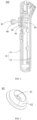
FIG. 1 is a schematic structural diagram of a remote controller according to an embodiment of the present invention; -
FIG. 2 is a cross-sectional view of the remote controller shown inFIG. 1 ; -
FIG. 3 is a schematic structural diagram of a protective cover for a control stick in the remote controller shown inFIG. 1 ; -
FIG. 4 is a cross-sectional view of the protective cover for a control stick shown inFIG. 3 ; -
FIG. 5 is a schematic structural diagram of a design of a protective cover for a control stick in the prior art; and -
FIG. 6 is a cross-sectional view of the protective cover for a control stick shown inFIG. 5 . - For ease of understanding of the present invention, the present invention is described below in more detail with reference to accompanying drawings and specific implementations. It should be noted that, when a component is expressed as "being fixed to" another component, the component may be directly on the another component, or one or more intermediate components may exist between the component and the another component. When a component is expressed as "being connected to" another component, the component may be directly connected to the another component, or one or more intermediate components may exist between the component and the another component. The terms "front", "rear", "left", and "right", and similar expressions used in this specification are merely used for an illustrative purpose.
- Unless otherwise defined, meanings of all technical and scientific terms used herein are the same as meanings generally understood by a person skilled in the technical field to which the present invention belongs. In this specification, terms used in the specification of the present invention are merely intended to describe objectives of the specific embodiments, but are not intended to limit the present invention. A term "and/or" used in this specification includes any or all combinations of one or more related listed items.
-
FIG. 1 is a schematic structural diagram of aremote controller 100 according to an embodiment of the present invention. Theremote controller 100 is configured to control an unmanned aerial vehicle aircraft. - The
remote controller 100 includes ahousing 10, adisplay screen 20, and a main control board mounted in the housing. An antenna assembly for receiving and transmitting a signal is further mounted on thehousing 10, and the antenna assembly is connected to the main control board. Thedisplay screen 20 is mounted on thehousing 10. Thedisplay screen 20 is connected to the antenna assembly and is configured to display an image captured by a camera on the unmanned aerial vehicle aircraft. - The
housing 10 includes a panel 11 and abottom plate 12, where thebottom plate 12 is fastened to the panel 11. Both the main control board and the antenna assembly are located in a cavity enclosed by the panel 11 and thebottom plate 12, and thedisplay screen 20 is mounted on the panel 11. - The
housing 10 is also provided with two sets of control assemblies, namely a first control assembly and a second control assembly. The first control assembly is configured to enable the unmanned aerial vehicle aircraft to perform a first operation, and the second control assembly is configured to enable the unmanned aerial vehicle aircraft to perform a second operation. - It should be noted that, the first operation refers to enabling the unmanned aerial vehicle aircraft to move back and forth, and the second operation refers to enabling the unmanned aerial vehicle aircraft to accelerate or decelerate or rotate clockwise or countercl ockwi se.
- In some embodiments, structures of the first control assembly and the second control assembly are the same.
- In this specification, a first control assembly is used as an example for description. The first control assembly includes a
control stick 30 and a protective cover for acontrol stick 40. Thecontrol stick 30 is mounted on the panel 11 through the protective cover for acontrol stick 40. Thecontrol stick 30 is configured to adjust the attitude and the lifting and descent of the unmanned aerial vehicle aircraft. For example, thecontrol stick 30 is moved forward to control a lift of the unmanned aerial vehicle aircraft, thecontrol stick 30 is moved backward to control a descent of the unmanned aerial vehicle aircraft, thecontrol stick 30 is moved to the left to adjust the unmanned aerial vehicle aircraft forward and is moved to right to adjust the unmanned aerial vehicle aircraft rightward. - Refer to
FIG. 3 andFIG. 4 together. The protective cover for acontrol stick 40 includes a firstelastic member 41, a secondelastic member 42, and abuffer member 43. Afirst accommodation groove 411 is provided in the middle of the firstelastic member 41, where thefirst accommodation groove 411 is configured to mount thecontrol stick 30. Thecontrol stick 30 is in an interference fit with thefirst accommodation groove 411, the secondelastic member 42 is arranged around the firstelastic member 41, and the secondelastic member 42 is fixed to the panel 11. Asecond accommodation groove 421 is provided in the middle of the secondelastic member 42, where thesecond accommodation groove 421 is connected to thefirst accommodation groove 411. Thebuffer member 43 is arranged in thesecond accommodation groove 421, thebuffer member 43 is connected between the firstelastic member 41 and the secondelastic member 42, and thebuffer member 43 is configured to enable thecontrol stick 30 to swing in thesecond accommodation cavity 421. In addition, when thecontrol stick 30 swings, thebuffer member 43 may further reduce the shaking of the secondelastic member 42 and prevent the secondelastic member 42 from deviating relative to thehousing 10, thereby increasing a protection level of theremote controller 100. - In some embodiments, the first
elastic member 41 and the secondelastic member 42 are coaxially arranged to facilitate an operation of the control stick, so that a movement stroke of thecontrol stick 30 in a circumferential direction is the same. - The circumferential direction is a direction surrounding the first elastic member.
- In some embodiments, one end of the first
elastic member 41 is located in thesecond accommodation groove 421, and the other end of the firstelastic member 41 protrudes from thesecond accommodation groove 421. - It may be understood that in another embodiment, the first
elastic member 41 may also be completely arranged outside thesecond accommodation groove 421. - In some embodiments, the first
elastic member 41 is straight-cylindrical when not affected by external force, and one end of thecontrol stick 30 connected to the firstelastic member 41 is also straight-cylindrical, so that thecontrol stick 30 is easily controlled when swinging under force, and theremote control stick 30 does not cause the control stick to swing greatly due to accidentally touching thecontrol stick 30 and affect the unmanned aerial vehicle aircraft. - In some embodiments, the second elastic member partially protrudes from the panel 11. Specifically, an outer surface of the second
elastic member 42 is provided with agroove 422, and the protective cover for acontrol stick 40 is clamped and fixed to the panel 11 through thegroove 422 to prevent dust and water vapor from entering an interior of the housing and damaging theremote controller 100. - In some embodiments, a
first end 431 of the buffer member is connected to the firstelastic member 41, and asecond end 432 of the buffer member is connected to the secondelastic member 42. The buffer member further includes abent portion 433, and thebent portion 433 is located between thefirst end 431 of the buffer member and thesecond end 432 of the buffer member. - A direction in which the first
elastic member 41 protrudes relative to thesecond accommodation groove 421 is a direction of the bottom of thesecond accommodation groove 421, and a direction opposite to the bottom is a top direction. - In some embodiments, to increase a swing stroke of the
control stick 30, thebent portion 433 is located at the bottom of thesecond accommodation groove 421. - Preferably, the
bent portion 433 is located in the middle of the firstelastic member 41 and the secondelastic member 42. - In some embodiments, to increase a swing stroke of the
control stick 30, thesecond end 432 of the buffer member is connected to the top of thesecond accommodation groove 421. - It should be noted that, when the
first end 431 of the buffer member, thebent portion 433, and thesecond end 432 of the buffer member are located on a same plane, thecontrol stick 30 has a maximum swing stroke. The larger the swing stroke of thecontrol stick 30 is, the larger the operable range of the unmanned aerial vehicle aircraft is. - In some embodiments, the first
elastic member 41, the secondelastic member 42, and thebuffer member 43 are integrally formed. - Refer to
FIG. 5 andFIG. 6 together, which shows a protective cover for acontrol stick 40a in the prior art. The protective cover for acontrol stick 40a includes a firstelastic member 41a, a secondelastic member 42a, and abuffer member 43a. Afirst end 431a of the buffer member is connected to the firstelastic member 41a, and asecond end 432a of the buffer member is connected to the secondelastic member 42a. Afirst accommodation cavity 411a is provided in the middle of the firstelastic member 41a, and asecond accommodation cavity 421a is provided in the middle of the secondelastic member 42a. Different from the protective cover for acontrol stick 40a, thebuffer member 43a is provided with a plurality ofbent portions 433a, and the arrangement of the plurality ofbent portions 433a increases an overall height of the protective cover for acontrol stick 40a. Therefore, after the protective cover for acontrol stick 40a is engaged with the panel 11, a larger part of the protective cover for acontrol stick 40a protrudes from the panel. - In addition, the first
elastic member 41a is in a shape of lug boss when not affected by external force. When a connecting end of thecontrol stick 30 and the firstelastic member 41a is straight-cylindrical, thecontrol stick 30 is less hindered when swinging in thefirst accommodation cavity 411a, so that the sensitivity of thecontrol stick 30 is relatively high, and when the control stick is accidentally touched, the control stick is easily out of control. - Compared with the prior art, the protective cover for a
control stick 40 in this application enables the control stick to be controlled easily. In addition, in the embodiments of this application, because thebuffer member 43 is designed with only one bent portion, compared with the prior art, the manufacturability of the protective cover for acontrol stick 40 is improved, and the design complexity of the protective cover for acontrol stick 40 is reduced at the same time. - In addition, due to the reduction of the bent portion, the overall height of the protective cover for a
control stick 40 is reduced, so that a height of the protective cover for acontrol stick 40 protruding from the panel 11 is reduced, thereby making theremote controller 100 more beautiful. - In some embodiments, the protective cover for a
control stick 40 is made of silica gel. In another embodiment, the protective cover for acontrol stick 40 is any elastic member having an elastic function, as long as the elastic member has good restoring force after elastic deformation, that is, the elastic member may be restored to an original state in a relatively short period of time after elastic deformation. - The protective cover for a
control stick 40 is fixed to the panel 11 of thehousing 10. Specifically, an adhesive material may be coated in thegroove 422, and after thegroove 422 is engaged with the panel 11, the protective cover for acontrol stick 40 may be fixed to the panel 11 through the adhesive material. - In some embodiments, the protective cover for a
control stick 40 may be fixed to thehousing 10 in another manner. For example, the first control assembly includes apressing plate 50, and the protective cover for acontrol stick 40 is fixed to the panel 11 of thehousing 10 through thepressing plate 50. Specifically, thepressing plate 50 is arranged around the firstelastic member 41. A first positioning hole is provided in the middle of thepressing plate 50. One end of the firstelastic member 41 protruding from thesecond accommodation groove 421 is arranged in the first positioning hole, and thepressing plate 50 abuts against the secondelastic member 42. - The
pressing plate 50 is provided with a mounting hole that is in a circumferential array, and the mounting hole is arranged around the positioning hole. The panel 11 is provided with a positioning post corresponding to a position of the mounting hole, and a second positioning hole is provided on the positioning post. After a screw passes through the mounting hole and the second positioning hole in sequence, thepressing plate 50 and the protective cover for acontrol stick 40 are fixed to the panel 11. - In some embodiments, the first control assembly further includes a
potentiometer 60, thecontrol stick 30 is connected to thepotentiometer 60, thepotentiometer 60 is connected to the main control board, the potentiometer is fixed on the panel 11, and thepotentiometer 60 is driven to swing by the swing of thecontrol stick 30. - The
control stick 30 is connected to thepotentiometer 60. Specifically, thecontrol stick 30 is provided with a threaded hole, and a shaft of thepotentiometer 60 is screwed to the threaded hole. Alternatively, thecontrol stick 30 is provided with a hole, and the hole of thecontrol stick 30 is an interference fit with the shaft of thepotentiometer 60. Alternatively, thecontrol stick 30 and the shaft of thepotentiometer 60 are fixedly connected through the adhesive material. - It should be noted that, the
potentiometer 60 has a multi-directional switch and can swing in a plurality of directions around. - It may be understood that the control stick of the second control assembly is configured to adjust a second operation of the unmanned aerial vehicle aircraft. For example, when it is turned to the right, the unmanned aerial vehicle aircraft rotates clockwise, and when it is turned to the left, the unmanned aerial vehicle aircraft rotates counterclockwise.
- In some embodiments, a
key switch 70 is further provided on the panel 11, and thekey switch 70 is connected to the antenna assembly. Thekey switch 70 includes a firstkey switch 71 and a secondkey switch 72. The firstkey switch 71 is configured to enable the unmanned aerial vehicle aircraft return immediately, and the secondkey switch 72 is configured to enable the unmanned aerial vehicle aircraft hover. - In some embodiments, to facilitate an operation of the
control stick 30 and avoid slipping when grasping thecontrol stick 30, a slip-proof sleeve 80 is mounted on thecontrol stick 30. - Compared with the prior art, the present invention provides a protective cover for a control stick and a remote controller. The bent portion is arranged on the buffer member, so that manufacturability of the protective cover for a control stick is improved and design complexity of the protective cover for a control stick is reduced.
- In addition, due to the reduction of the bent portion, an overall height of the protective cover for a control stick is reduced, so that a height of the protective cover for a control stick protruding from the panel is reduced, thereby making the remote controller more beautiful.
- It should be noted that, the specification of the present invention and the accompanying drawings thereof illustrate preferred embodiments of the present invention. However, the present invention may be implemented in various different forms, and is not limited to the embodiments described in this specification. These embodiments are not intended to be an additional limitation on the content of the present invention, and are described for the purpose of providing a more thorough and comprehensive understanding of the content disclosed in the present invention. In addition, if the above technical features continue to be combined with each other to form various embodiments not listed above, and all such embodiments shall be construed as falling within the scope of the specification of the present invention. Further, a person of ordinary skill in the art may make improvements or variations according to the above descriptions, and such improvements and variations shall all fall within the protection scope of the appended claims of this application.
Claims (11)
- A protective cover for a control stick, applied to a remote controller, and comprising:a first elastic member, wherein a first accommodation groove is provided in a middle of the first elastic member, and the first accommodation groove is configured to mount the control stick;a second elastic member, arranged around the first elastic member, wherein the second elastic member is fixed to a panel of the remote controller; anda buffer member, connected between the first elastic member and the second elastic member, wherein the buffer member comprises a bent portion.
- The protective cover for a control stick according to claim 1, wherein
a second accommodation groove is provided in a middle of the second elastic member, the second accommodation groove is in communication with the first accommodation groove, and the buffer member is arranged in the second accommodation groove. - The protective cover for a control stick according to claim 2, wherein
one end of the first elastic member is located in the second accommodation groove, and another end of the first elastic member protrudes from the second accommodation groove. - The protective cover for a control stick according to claim 3, wherein
in a protruding direction of the first elastic member, the bent portion is located at a bottom of the second accommodation groove. - The protective cover for a control stick according to claim 3, wherein
in a protruding direction of the first elastic member, the buffer member is connected to a top of the second accommodation groove. - The protective cover for a control stick according to claim 1, wherein
the first elastic member and the second elastic member are coaxially arranged. - The protective cover for a control stick according to claim 1, wherein
an outer surface of the second elastic member is provided with a groove, and the groove is engaged with a panel of a housing of the remote controller. - The protective cover for a control stick according to claim 1, wherein
the first elastic member, the second elastic member, and the buffer member are integrally formed. - The protective cover for a control stick according to claim 1, wherein
the protective cover for a control stick is made of silica gel. - A remote controller, comprising:a housing;an antenna assembly, accommodated in the housing, wherein the antenna assembly is communicatively connected to an unmanned aerial vehicle;a main control board, accommodated in the housing, wherein the main control board is connected to the antenna assembly;the protective cover for a control stick according to any one of claims 1 to 9, wherein the protective cover for a control stick is fixed to the housing and partially protrudes from the housing; anda control stick, fixed to the first accommodation groove, wherein the control stick is connected to the main control board.
- The remote controller according to claim 10,
further comprising a display screen, wherein the display screen is connected to the antenna assembly.
Applications Claiming Priority (2)
| Application Number | Priority Date | Filing Date | Title |
|---|---|---|---|
| CN202110414065.0A CN113192311A (en) | 2021-04-16 | 2021-04-16 | Rocking handle protection casing and remote controller |
| PCT/CN2022/084129 WO2022218156A1 (en) | 2021-04-16 | 2022-03-30 | Rocking handle protective cover and remote control |
Publications (2)
| Publication Number | Publication Date |
|---|---|
| EP4325326A1 true EP4325326A1 (en) | 2024-02-21 |
| EP4325326A4 EP4325326A4 (en) | 2024-10-02 |
Family
ID=76977214
Family Applications (1)
| Application Number | Title | Priority Date | Filing Date |
|---|---|---|---|
| EP22787384.1A Pending EP4325326A4 (en) | 2021-04-16 | 2022-03-30 | Rocking handle protective cover and remote control |
Country Status (4)
| Country | Link |
|---|---|
| US (1) | US12625574B2 (en) |
| EP (1) | EP4325326A4 (en) |
| CN (1) | CN113192311A (en) |
| WO (1) | WO2022218156A1 (en) |
Families Citing this family (2)
| Publication number | Priority date | Publication date | Assignee | Title |
|---|---|---|---|---|
| CN113192311A (en) * | 2021-04-16 | 2021-07-30 | 深圳市道通智能航空技术股份有限公司 | Rocking handle protection casing and remote controller |
| USD1091487S1 (en) * | 2023-12-01 | 2025-09-02 | Autel Robotics Co., Ltd. | Remote control |
Family Cites Families (17)
| Publication number | Priority date | Publication date | Assignee | Title |
|---|---|---|---|---|
| DE19636643C1 (en) * | 1996-09-10 | 1998-02-12 | Preh Elektro Feinmechanik | Knob top |
| US5831554A (en) * | 1997-09-08 | 1998-11-03 | Joseph Pollak Corporation | Angular position sensor for pivoted control devices |
| JP3954784B2 (en) * | 2000-08-22 | 2007-08-08 | アルプス電気株式会社 | Multi-directional input device |
| JP4090274B2 (en) * | 2002-05-27 | 2008-05-28 | 帝国通信工業株式会社 | Multi-directional push switch |
| US10073488B2 (en) * | 2014-09-11 | 2018-09-11 | Grayhill, Inc. | Multifunction joystick apparatus and a method for using same |
| TWI576725B (en) * | 2016-04-22 | 2017-04-01 | 致伸科技股份有限公司 | Joystick module |
| CN206045411U (en) * | 2016-06-04 | 2017-03-29 | 深圳市兴达实电子有限公司 | A kind of remote control unit for aircraft remote control |
| CN206098255U (en) * | 2016-09-22 | 2017-04-12 | 深圳市大疆创新科技有限公司 | Rocker device and install bracelet of rocker device |
| CN207149056U (en) * | 2017-05-19 | 2018-03-27 | 深圳市大疆创新科技有限公司 | Remote control |
| CN109426298B (en) * | 2017-09-01 | 2024-04-12 | 深圳市道通智能航空技术股份有限公司 | Control rod assembly and remote controller |
| CN207557694U (en) * | 2017-09-01 | 2018-06-29 | 深圳市道通智能航空技术有限公司 | Protective case, control bar assembly and remote controler |
| CN207764655U (en) * | 2017-12-15 | 2018-08-24 | 广州天翔航空科技有限公司 | Hand-held earth station and unmanned plane self-driving system |
| CN113540762B (en) * | 2018-06-27 | 2023-05-16 | 深圳市大疆创新科技有限公司 | Antenna structure |
| CN211752429U (en) * | 2020-02-24 | 2020-10-27 | Oppo广东移动通信有限公司 | Laminates, Protective Housings, and Control Handles |
| CN212569576U (en) * | 2020-06-18 | 2021-02-19 | 浙江华飞智能科技有限公司 | Rocker device and remote controller |
| CN215219894U (en) * | 2021-04-16 | 2021-12-17 | 深圳市道通智能航空技术股份有限公司 | Rocking handle protection casing and remote controller |
| CN113192311A (en) * | 2021-04-16 | 2021-07-30 | 深圳市道通智能航空技术股份有限公司 | Rocking handle protection casing and remote controller |
-
2021
- 2021-04-16 CN CN202110414065.0A patent/CN113192311A/en active Pending
-
2022
- 2022-03-30 EP EP22787384.1A patent/EP4325326A4/en active Pending
- 2022-03-30 WO PCT/CN2022/084129 patent/WO2022218156A1/en not_active Ceased
-
2023
- 2023-10-16 US US18/380,638 patent/US12625574B2/en active Active
Also Published As
| Publication number | Publication date |
|---|---|
| EP4325326A4 (en) | 2024-10-02 |
| CN113192311A (en) | 2021-07-30 |
| WO2022218156A1 (en) | 2022-10-20 |
| US12625574B2 (en) | 2026-05-12 |
| US20240045525A1 (en) | 2024-02-08 |
Similar Documents
| Publication | Publication Date | Title |
|---|---|---|
| US12625574B2 (en) | Protective cover for control stick and remote controller | |
| US8287326B2 (en) | Remote controller for aircraft model | |
| US9343837B2 (en) | Docking apparatus of electronic apparatus | |
| US20160179091A1 (en) | Tactical robot controller | |
| CN105667775A (en) | Mobile phone App based remotely-controllable miniature aerial-photographing four-rotor aircraft and control method thereof | |
| US20190243221A1 (en) | Camera dolly, remote-controlled camera dolly system and camera dolly photographing control method | |
| WO2019242225A1 (en) | Unmanned aerial vehicle, arm assembly and rotary shaft mechanism thereof | |
| KR20150088639A (en) | Unmanned aerial vehicle having a camera | |
| CN105289010A (en) | Handle of unmanned aerial vehicle | |
| EP4083759B1 (en) | Input device | |
| WO2022027234A1 (en) | Remote control, remote control kit, and flight kit | |
| CN103034185A (en) | Communication system and ground station thereof | |
| WO2022213862A1 (en) | Unmanned aerial vehicle remote control and unmanned aerial vehicle assembly | |
| CN215219894U (en) | Rocking handle protection casing and remote controller | |
| CN217864705U (en) | Cross axle operating lever | |
| CN205221109U (en) | Multiaxis manned vehicle | |
| CN206564585U (en) | Wearable remote control and unmanned vehicle system | |
| CN209388156U (en) | Modularization unmanned aerial vehicle ground control system | |
| CN218986992U (en) | Anti-seismic landing leg | |
| CN212243852U (en) | Display and control system for airplane | |
| CN105302157A (en) | Unmanned plane control handle | |
| CN205405137U (en) | Unmanned aerial vehicle system based on internet remote control | |
| CN208255837U (en) | A kind of aviation track ball mouse | |
| CN205750528U (en) | A kind of unmanned aerial vehicle (UAV) control device carrying out state of flight and camera angle switching control | |
| CN207677557U (en) | Motor fixing structure, motor assembly and aircraft equipped with motor fixing structure |
Legal Events
| Date | Code | Title | Description |
|---|---|---|---|
| STAA | Information on the status of an ep patent application or granted ep patent |
Free format text: STATUS: THE INTERNATIONAL PUBLICATION HAS BEEN MADE |
|
| PUAI | Public reference made under article 153(3) epc to a published international application that has entered the european phase |
Free format text: ORIGINAL CODE: 0009012 |
|
| STAA | Information on the status of an ep patent application or granted ep patent |
Free format text: STATUS: REQUEST FOR EXAMINATION WAS MADE |
|
| 17P | Request for examination filed |
Effective date: 20231116 |
|
| AK | Designated contracting states |
Kind code of ref document: A1 Designated state(s): AL AT BE BG CH CY CZ DE DK EE ES FI FR GB GR HR HU IE IS IT LI LT LU LV MC MK MT NL NO PL PT RO RS SE SI SK SM TR |
|
| DAV | Request for validation of the european patent (deleted) | ||
| DAX | Request for extension of the european patent (deleted) | ||
| REG | Reference to a national code |
Ref country code: DE Ref legal event code: R079 Free format text: PREVIOUS MAIN CLASS: G05G0001040000 Ipc: G05G0025040000 |
|
| A4 | Supplementary search report drawn up and despatched |
Effective date: 20240904 |
|
| RIC1 | Information provided on ipc code assigned before grant |
Ipc: G06F 3/039 20130101ALI20240829BHEP Ipc: G06F 3/0338 20130101ALI20240829BHEP Ipc: G05G 9/047 20060101ALI20240829BHEP Ipc: G05G 25/04 20060101AFI20240829BHEP |