EP4325157A2 - Devices, systems, and methods for removing heat from a nuclear reactor core - Google Patents
Devices, systems, and methods for removing heat from a nuclear reactor core Download PDFInfo
- Publication number
- EP4325157A2 EP4325157A2 EP23215096.1A EP23215096A EP4325157A2 EP 4325157 A2 EP4325157 A2 EP 4325157A2 EP 23215096 A EP23215096 A EP 23215096A EP 4325157 A2 EP4325157 A2 EP 4325157A2
- Authority
- EP
- European Patent Office
- Prior art keywords
- heat pipe
- heat
- wick
- inner housing
- outer housing
- Prior art date
- Legal status (The legal status is an assumption and is not a legal conclusion. Google has not performed a legal analysis and makes no representation as to the accuracy of the status listed.)
- Pending
Links
Images



Classifications
-
- G—PHYSICS
- G21—NUCLEAR PHYSICS; NUCLEAR ENGINEERING
- G21C—NUCLEAR REACTORS
- G21C15/00—Cooling arrangements within the pressure vessel containing the core; Selection of specific coolants
- G21C15/24—Promoting flow of the coolant
- G21C15/257—Promoting flow of the coolant using heat-pipes
-
- F—MECHANICAL ENGINEERING; LIGHTING; HEATING; WEAPONS; BLASTING
- F28—HEAT EXCHANGE IN GENERAL
- F28D—HEAT-EXCHANGE APPARATUS, NOT PROVIDED FOR IN ANOTHER SUBCLASS, IN WHICH THE HEAT-EXCHANGE MEDIA DO NOT COME INTO DIRECT CONTACT
- F28D15/00—Heat-exchange apparatus with the intermediate heat-transfer medium in closed tubes passing into or through the conduit walls ; Heat-exchange apparatus employing intermediate heat-transfer medium or bodies
- F28D15/02—Heat-exchange apparatus with the intermediate heat-transfer medium in closed tubes passing into or through the conduit walls ; Heat-exchange apparatus employing intermediate heat-transfer medium or bodies in which the medium condenses and evaporates, e.g. heat pipes
- F28D15/04—Heat-exchange apparatus with the intermediate heat-transfer medium in closed tubes passing into or through the conduit walls ; Heat-exchange apparatus employing intermediate heat-transfer medium or bodies in which the medium condenses and evaporates, e.g. heat pipes with tubes having a capillary structure
- F28D15/046—Heat-exchange apparatus with the intermediate heat-transfer medium in closed tubes passing into or through the conduit walls ; Heat-exchange apparatus employing intermediate heat-transfer medium or bodies in which the medium condenses and evaporates, e.g. heat pipes with tubes having a capillary structure characterised by the material or the construction of the capillary structure
-
- F—MECHANICAL ENGINEERING; LIGHTING; HEATING; WEAPONS; BLASTING
- F28—HEAT EXCHANGE IN GENERAL
- F28D—HEAT-EXCHANGE APPARATUS, NOT PROVIDED FOR IN ANOTHER SUBCLASS, IN WHICH THE HEAT-EXCHANGE MEDIA DO NOT COME INTO DIRECT CONTACT
- F28D21/00—Heat-exchange apparatus not covered by any of the groups F28D1/00 - F28D20/00
- F28D2021/0019—Other heat exchangers for particular applications; Heat exchange systems not otherwise provided for
- F28D2021/0054—Other heat exchangers for particular applications; Heat exchange systems not otherwise provided for for nuclear applications
-
- Y—GENERAL TAGGING OF NEW TECHNOLOGICAL DEVELOPMENTS; GENERAL TAGGING OF CROSS-SECTIONAL TECHNOLOGIES SPANNING OVER SEVERAL SECTIONS OF THE IPC; TECHNICAL SUBJECTS COVERED BY FORMER USPC CROSS-REFERENCE ART COLLECTIONS [XRACs] AND DIGESTS
- Y02—TECHNOLOGIES OR APPLICATIONS FOR MITIGATION OR ADAPTATION AGAINST CLIMATE CHANGE
- Y02E—REDUCTION OF GREENHOUSE GAS [GHG] EMISSIONS, RELATED TO ENERGY GENERATION, TRANSMISSION OR DISTRIBUTION
- Y02E30/00—Energy generation of nuclear origin
- Y02E30/30—Nuclear fission reactors
Definitions
- the present disclosure is generally related to nuclear power generation and, more particularly, is directed to improved devices, systems, and methods configured to remove thermal energy from a nuclear reactor core.
- US Patent No. 3,414,475 discloses a tubular heat pipe comprising an evaporization zone, with an internally mounted fissile heat source, and a condensation zone, with external secondary cooling means.
- the pipe is at least partially filled with a liquid coolant which evaporates in the evaporization zone and returns, after condensing, along the inner surface of the pipe walls to the evaporization zone.
- US Patent No. 5,000,252 discloses a thermal management system including micro heat pipes extending radially outward from a heat sink that surrounds a heat source, to conduct thermal energy from the heat source, and means for dissipating thermal energy from the heat sink to an ultimate heat sink.
- 10,559,389 B2 discloses a modular nuclear reactor comprising a plurality of sections arranged in a pattern, each including a tank comprising a front plate, a back plate, side plates, a top plate and a bottom plate, and a side reflector material surrounding the sections.
- Grid plates each comprising apertures, are located within the tank vertically separated from an adjacent grid plate.
- the tank further includes fuel elements extending through each grid plate. Heat pipes extend through each grid plate, the top plate, and an upper reflector.
- a heat pipe configured to remove heat from a core of a nuclear reactor.
- the heat pipe includes a length and an inner housing with an outer surface, wherein the inner housing defines an inner volume configured to accommodate a heat source.
- the heat pipe further includes an outer housing with an inner surface configured about the inner housing and the heat source.
- the heat pipe further includes a wick positioned between the inner housing and the outer housing and extending along at least a portion of the length of the heat pipe, wherein the wick includes a capillary material, wherein the wick is configured to contact at least a portion of the outer surface of the inner housing, wherein the wick is configured to contact at least a portion of the inner surface of the outer housing, and wherein the wick defines an intermediate volume between the inner housing and the outer housing.
- the heat pipe further includes a working fluid within the intermediate volume, wherein the working fluid is configured to evaporate at a first end of the heat pipe, wherein the working fluid is further configured to condense at a second end of the heat pipe adjacent to a heat exchanger, wherein the wick is configured to return working fluid that has condensed at the second end of the heat pipe to the first end of the heat pipe, and wherein the evaporation and condensation of the working fluid is configured to transfer heat from the first end of the heat pipe to the second end of the heat pipe for dissipation via the heat exchanger.
- a heat pipe configured to remove heat from a core of a nuclear reactor.
- the heat pipe can include an inner housing defining an inner volume configured to accommodate a heat source and an outer housing configured about the inner housing and the heat source.
- the heat pipe can further include a wick positioned between at least a portion of the inner housing and at least a portion of the outer housing, wherein the wick includes a capillary material, and wherein the wick defines an intermediate volume between the inner housing and the outer housing.
- the heat pipe can further include a working fluid within the intermediate volume, wherein the working fluid is configured to evaporate at a first end of the heat pipe, wherein the working fluid is further configured to condense at a second end of the heat pipe adjacent to a heat exchanger, and wherein the wick is configured to return working fluid that has condensed at the second end of the heat pipe to the first end of the heat pipe.
- the present disclosure is directed to devices, systems, and methods for removing heat from a nuclear reactor core.
- the management of thermal energy within a core is important for nuclear reactors. For example, if the core of a nuclear reactor overheats, the reactor may be taken off line for subsequent repair, the usable life of the core can be shortened, and the reactor can become potentially hazardous to operate.
- the removal of heat from the core of a nuclear reactor becomes even more challenging-and critical-as reactors decrease in size and become more modular.
- Some compact reactors function as a "nuclear battery" which uses energy from the fission of nuclear materials (e.g. uranium) to generate electricity. Accordingly, compact reactors can optimize reactor output while reducing reactor size. However, as the size of the reactor is reduced, it becomes increasingly difficult to remove heat from the system. Thermal management within a compact reactor can be accomplished via a configuration of heat pipes.
- each heat pipe of a compact reactor can include a small amount of a working fluid (e.g. sodium liquid) configured to move heat from the reactor core to a heat exchanger, where it can be utilized to generate electricity.
- a working fluid e.g. sodium liquid
- heat pipe based reactors do not require mechanical pumps, valves, loop piping, and the associated auxiliary systems required to cool a conventional reactor, which further reduces the size of the overall reactor.
- heat pipe performance and configuration remain a key design consideration for compact reactors. Since the heat pipes streamline the thermal management system by eliminating the need for auxiliary cooling components, the heat pipe configuration itself becomes a constraint for further reductions in reactor size.
- Conventional heat pipes include a single tube that defines an inner tube volume filled with working fluid, and a heat source and sink positioned external to the conventional heat pipe. Theoretical research regarding the use of concentric, annular heat pipes with a single wick positioned at the inner heat pipe wall has been performed at Newcastle University. Additionally, annular heat pipes are implemented in Isothermal Furnace Liners, not to transport large amount of heat, but to create a uniform temperature distribution for temperature calibration.
- the device 100 can be a heat pipe configured for implementation within a compact nuclear reactor.
- the heat pipe 100 can include an inner housing 104 and an outer housing 108.
- the inner housing 104 of FIG. 1 can further include an outer surface 106 positioned within the heat pipe 100 such that it faces an inner surface 110 of the outer housing 108.
- the heat pipe 100 can include an annular configuration with a circular outer housing 108 concentrically positioned about a circular inner housing 104.
- a length of the heat pipe 100 can extend along the centerline about which the inner housing 104 and outer housing 108 are concentrically positioned, thereby forming a tube-like configuration.
- the inner housing 104 can include an outer diameter D1 less than an inner diameter D2 of the outer housing 108 to achieve the aforementioned annular configuration.
- the non-limiting circularly configured aspect of FIG. 1 is exclusively presented for illustrative purposes. It shall be appreciated that the term "diameter”, as used by the present disclosure, shall include any dimension that extends away from a center point of the device 100. As such, it shall be appreciated that the term “diameter" is not intended to limit the device 100 to a circular configuration.
- FIG. 1 depicts a heat pipe 100 with circular, concentrically oriented housings 104, 108
- any geometric configuration can be implemented for either the inner housing 104 and outer housing 108.
- other non-limiting aspects of the present disclosure include an inner housing 104 and outer housing 108 of varying configurations ( e.g. square, rectangular, triangular, octagonal).
- the inner housing 104 can include a first geometric configuration and the outer housing 108 can include a second geometric configuration that is different from the first.
- the inner housing 104 can include an octagonal configuration and the outer housing 108 can include a circular configuration, such that at least a portion the outer surface 106 of the inner housing 104 is not parallel to a corresponding portion of the inner surface 110 of the outer housing 108.
- the inner housing 104 can further define a volume 103 configured to accommodate an internal heat source 102, such that the heat pipe 100 substantially surrounds the heat source 102 when properly inserted within the volume 103.
- the heat source 102 can include any material configured to generate thermal energy, such as a fuel source (e.g. uranium nitride) or a moderator (e.g. a hydride-based moderator) of the nuclear reactor.
- a fuel source e.g. uranium nitride
- a moderator e.g. a hydride-based moderator
- the heat source 102 can be in physical contact with the inner surface 107 of the inner housing 104 when properly inserted.
- the volume 103 can be filled with an intermediary material configured to enhance heat transfer between heat source 102. Regardless, the interface between the heat source 102 and the heat pipe 100 can be configured to efficiently transfer heat away from the heat source 102.
- the heat pipe 100 can further include a wick 112 positioned within the intermediate volume 111 between the inner housing 104 and the outer housing 108.
- the wick 112 can be configured to contact at least a portion of the outer surface 106 of the inner housing 104 and at least a portion of the inner surface 110 of the outer housing 108.
- the wick 112 can include an inner surface 116 positioned in thermal communication with the outer surface 106 of the inner housing 104 and an outer surface 118 positioned in thermal communication with the inner surface 110 of the outer housing 108.
- the surfaces 116, 118 of the wick 112 can be configured to mechanically contact the surfaces 106, 110 of the housings 104, 108.
- the wick 112 can further include a plurality of ribs 120 mechanically coupled to at least a portion of the inner surface 116 and outer surface 118 of the wick 112.
- the plurality of ribs 120 can include either the same or a similar wicking material to the wick 112.
- the ribs 120 can be configured to directly contact the surfaces 106, 110 of the housings 104, 108, themselves.
- ribs 120 are oriented in any number of varying configurations ( e.g. zig-zag, circular, cruciform).
- a working fluid e.g. sodium liquid
- the wick 112 can be composed of one or more materials that include capillary properties (e.g. any porous material).
- the heat pipe 100 can be positioned within the nuclear reactor such that one of its ends is positioned within a condenser of the nuclear reactor.
- working fluid that has condensed on a cold side of the heat pipe 100 can be returned to a hot side of the heat pipe 100 for evaporation due to the capillary properties of the wick 112, thereby renewing the heat transfer cycle.
- the heat pipe 100 of FIG. 1 can more efficiently manage the thermal energy produced by a compact nuclear reactor when compared to known single-tube heat pipe configurations. This can result in improved performance and reliability and result in compact reactors of reduced size.
- the device 200 can be similarly configured to the heat pipe 100 of FIG. 1 .
- the device 200 can include a heat pipe configured for implementation within a nuclear reactor, with an inner housing 204 and an outer housing 208.
- the inner housing 204 of FIG. 2 can include an outer surface 206 positioned within the heat pipe 200 such that it faces an inner surface 210 of the outer housing 208.
- the heat pipe 200 can include an annular configuration with a circular outer housing 208 concentrically positioned about a circular inner housing 204, and the heat pipe 200 once again extends in a tube-like configuration.
- the annular configuration of FIG. 2 is intended for illustrative purposes only. Accordingly, in other non-limiting aspects, the heat pipe 200 can include any number of geometrical configurations ( e.g. square, rectangular, triangular, octagonal).
- the inner housing 204 can define a volume 203 configured to accommodate an internal heat source 202.
- the heat pipe 200 can further include a cladding layer 222 concentrically oriented about the heat source 202, the inner housing 204, and the outer housing 208.
- the cladding layer 222 can include a cladding diameter D3 that is greater than the inner diameter D1 and the outer diameter D1, such that the cladding 222 substantially surrounds the components of the heat pipe 200 that were discussed in reference to the heat pipe 100 of FIG. 1 .
- the cladding 222 of FIG. 2 includes a circular configuration, it too can include any number of different geometrical configurations, even if the inner housing 204 and outer housing 208 are circular.
- the cladding layer 222 can define a second intermediate volume 217 between an inner surface 226 of the cladding layer 222 and an outer surface 224 of the outer housing 208.
- the cladding layer 222 can include a thin-walled tube made of a material configured to contain any nuclear material positioned within the heat pipe 200. Accordingly, the cladding layer 222 can be specifically configured to prevent the corrosion of the and thus, prevent the release of detrimental and potentially hazardous materials into an operating environment.
- the heat pipe 200 can further include a wick 212 positioned within an intermediate volume 211 defined between the inner housing 204 and the outer housing 208.
- the wick 212 can be configured to contact at least a portion of the outer surface 206 of the inner housing 204 and at least a portion of the inner surface 210 of the outer housing 208.
- the wick 212 can include an inner surface 216 positioned in thermal communication with the outer surface 206 of the inner housing 204 and an outer surface 218 positioned in thermal communication with the inner surface 210 of the outer housing 208.
- the surfaces 216, 218 of the wick 212 can be configured to mechanically contact the surfaces 206, 210 of the housings 204, 208.
- the wick 212 can further include a plurality of ribs 220 mechanically coupled to at least a portion of the inner surface 216 and outer surface 218 of the wick 212.
- the plurality of ribs 220 can include either the same or a similar wicking material to the wick 212.
- the ribs 220 can be configured to directly contact the surfaces 206, 210 of the housings 204, 208, themselves.
- ribs 220 depicted in FIG. 2 extend radially outward from the center of the concentrically oriented inner and outer housing 204, 208, it shall be appreciated that the present disclosure contemplates other non-limiting aspects wherein the ribs 220 are oriented in any number of varying configurations ( e.g. zig-zag, circular, cruciform).
- a working fluid e.g. sodium liquid, and/or the like
- the wick 212 can be composed of one or more materials that include capillary properties (e.g. any porous material).
- the heat pipe 200 can be positioned within the nuclear reactor such that one of its ends is positioned within a condenser of the nuclear reactor.
- working fluid that has condensed on a cold side of the heat pipe 200 can be returned to a hot side of the heat pipe 200 for evaporation due to the capillary properties of the wick 212, thereby renewing the heat transfer cycle.
- the heat pipe 200 of FIG. 2 can more efficiently manage the thermal energy produced by a compact nuclear reactor when compared to known single-tube heat pipe configurations. This can result in improved performance and reliability and result in compact reactors of reduced size.
- the heat pipe 200 of FIG. 2 can include a moderator-type 202 heat source (e.g. hydride-based moderator, and/or the like) positioned within the volume 203, and a fuel 228 (e.g. uranium nitride, and/or the like) positioned within the second intermediate volume 217, as defined by the cladding layer 222.
- a moderator-type 202 heat source e.g. hydride-based moderator, and/or the like
- a fuel 228 e.g. uranium nitride, and/or the like
- heat pipes 200 can include multiple heat sources 202, 228 integrated within a heat transfer media, or core block (e.g., graphite, and/or the like), of the nuclear reactor. Accordingly, in the event of a heat pipe 200 failure, adjacent heat pipes 200 can compensate for the failure by transferring excess heat away from the core.
- core block e.g., graphite, and/or the like
- FIGS. 1 and 2 include heat pipes 100, 200 with integrated heat sources 102, 202
- the present disclosure contemplates other non-limiting aspects featuring a wide variety of arrangements of the heat pipes 100, 200 and heat sources 102, 202.
- the wick 212 of the heat pipe 200 of FIG. 2 can be surrounded by a heat source 202, depending on whether the intended application and/or user preference can accommodate for the less efficient use of space.
- the fuel 228 can be surrounded by the wick 212 of the heat pipe 200 of FIG. 2 and the moderator 202 can be configured to surround the wick 212 of the heat pipe 200.
- the position of the fuel 228 and moderator 202 of FIG. 2 can be inverted, depending on whether the intended application and/or user preference can accommodate for less efficient cooling in the event of heat pipe failure.
- the user might be motivated to optimize other variables at the expense of nuclear reactor size and/or efficiency of heat transfer, which provides the heat pipe 200 design of FIG. 2 with a certain degree of customization.
- optimization of the heat pipe 200 design depends on the intended application and/or user preference for the nuclear reactor design, both of which are increasing in importance due to the emergence of micro-reactors.
- FIG. 3 a top view of a unit cell 300 including a plurality of devices 302 configured to remove heat from the core of a nuclear reactor is depicted in accordance with at least one non-limiting aspect of the present disclosure.
- the unit cell 300 of FIG. 3 includes 19 devices 302, the present disclosure contemplates other non-limiting aspects wherein the unit cell 300 includes any number of devices 302.
- the hexagonal configuration of the unit cell 300 of FIG. 3 is exclusively presented for illustrative purposes.
- the unit cell 300 of FIG. 3 can include any number of geometric configurations, depending on the desired output and thermal properties of the core.
- each device 302 of the plurality of devices 302 can be configured to substantially surround an integrated heat source 304 of the core.
- the heat source 304 can include either a fuel rod, a moderator, or combinations therefor.
- each device 302 of the plurality of devices 302 can further include an assembly 306 configured to surround the integrated heat source 304.
- the assembly 306 can include any of the features discussed in reference to FIGS. 1 and 2 , including a wick 112, 212 of a heat pipe 100, 200 and/or a plurality of ribs 120, 220 configured to transfer heat away from the integrated heat source 304.
- the assembly 306 can further include a cladding 222 that defines a second intermediate volume 217 configured to accommodate a fuel 228, as discussed in reference to FIG. 2 .
- each device 302 of the plurality of devices 302 can include a different configuration.
- a first device 302 can include the device 100 configuration of FIG. 1 and a second device 302 can include the device 200 configuration of FIG. 2 .
- each device 302 of the unit cell 300 can be particularly arranged to be adjacent to a number of other devices 302.
- Adjacent devices 302 can be positioned at a predetermined distance from one another, such that thermal energy generated by the integrated heat sources 304 of any given device 302 can be effectively transferred away from the core in the event of a heat pipe failure. Since conventional heat pipes are typically surrounded by the heat sources they are intended to cool, adjacent heat pipes are limited in their ability assist in mitigating temperature increases if a first heat pipe fails. Accordingly, unit cell 300 configuration of FIG. 3 offers a significant improvement and benefit over known devices. Additionally and/or alternatively, the unit cell 300 can include a core block including a material with preferable thermal properties (e.g.
- the temperature sensors can detect the increase in temperature and determine whether or not it meets or exceeds a predetermined threshold, after which a nuclear reactor shutdown protocol can be commenced.
- the system 400 includes a horizontally oriented device, such as a heat pipe 401, integrated with a condenser 404 of the nuclear reactor.
- the heat pipe 401 is configured about a heat source 402, such as fuel or a moderator, the length of which defines an evaporating section of the heat pipe 401, which operates at an evaporating temperature T e .
- the heat pipe 401 can further include one or more internal end caps 408, one of which defines an adiabatic section of the heat pipe 401 that operates at an adiabatic temperature T sat .
- the heat pipe 401 can further include a cover gas 410 positioned within the adiabatic section.
- the heat pipe 401 can terminate in the condenser 404 of the nuclear reactor, which operates at a condensing temperature T c .
- the evaporating temperature T e is greater than the adiabatic temperature T sat and the adiabatic temperature T sat is greater than the condensing temperature T c .
- the evaporating section, the adiabatic section, and the condensing section of the heat pipe 401 can constitute a length L of the heat pipe 401. Accordingly, a working fluid 416 within the heat pipe 401 can evaporate from the heat generated by the integrated heat source 402, travel the length of the heat pipe 401 through the adiabatic section to the condenser 404, where it is cooled and condenses.
- the heat pipe 401 of FIG. 4 can include external end caps 406, as well as a first external wick 412 and a second internal wick 414. Either the external end caps 406, the internal end caps 408, or both can connect the external wick 412 and the internal wick 414. Alternatively and/or additionally, one or more ribs (e.g. the ribs 120, 220 of devices 100, 200 depicted in FIGS. 1 and 2 ) can also be configured to connect an external wick 412 and internal wick 414 of the heat pipe 401. Regardless, the external wick 412 and internal wick 414 can cooperate to connect the multiple surfaces of the heat pipe 401, which creates a larger surface area for conduction and convection.
- ribs e.g. the ribs 120, 220 of devices 100, 200 depicted in FIGS. 1 and 2
- the external wick 412 and internal wick 414 can cooperate to connect the multiple surfaces of the heat pipe 401, which creates a larger surface area for conduction
- connection of the external wick 412 and the internal wick 414 can establish a common volume of the heat pipe 401, while retaining its discrete sections and operating temperatures.
- This connection can be positioned on a condenser side of the heat pipe 401 for the horizontally configured system 500 of FIG. 5 .
- the heat pipe 401 with an integral heat source and/or moderator can provide the foregoing benefits with and without wicks 412, 414, and can be placed in any orientation, including an orientation that uses gravity to move the working fluid within the heat pipe (e.g., a thermosiphon), as will be discussed in further detail with reference to FIG. 5 .
- FIG. 5 a side view of another system 500 configured to remove heat from a core of a nuclear reactor is depicted in accordance with at least one non-limiting aspect of the present disclosure.
- the system 500 includes a vertically oriented device, such as a heat pipe 501, integrated with a condenser 504 of the nuclear reactor.
- the system 500 is similarly configured to the system 400 of FIG. 4 .
- the system 500 of FIG. 5 is vertically configured and thus, can operate like a thermosiphon for moving the working fluid 516.
- the heat pipe 501 is configured about a heat source 502, such as fuel or a moderator, the length of which defines an evaporating section of the heat pipe 501, which operates at an evaporating temperature T e .
- the heat pipe 501 can further include one or more internal end caps 508, one of which defines an adiabatic section of the heat pipe 501 that operates at an adiabatic temperature T sat .
- the heat pipe 501 can further include a cover gas positioned within the adiabatic section.
- the heat pipe 501 can terminate in the condenser 504 of the nuclear reactor, which operates at a condensing temperature T c .
- the evaporating section, the adiabatic section, and the condensing section of the heat pipe 501 can constitute a length L of the heat pipe 501.
- the evaporating temperature T e is greater than the adiabatic temperature T sat and the adiabatic temperature T sat is greater than the condensing temperature T c .
- a working fluid 516 within the heat pipe 501 can evaporate from the heat generated by the integrated heat source 502, travel the length of the heat pipe 501 through the adiabatic section to the condenser 504, where it is cooled and condenses.
- the heat pipe 501 can include external end caps 506.
- the heat pipe can include a wicking feature 512 exclusively positioned within the evaporating section.
- the wicking feature 512 can include either grooves, a partial wick, and/or the like.
- the heat pipe does not require as many wicking features 412, 414 as the horizontally configured system 400 of FIG. 4 . This is because gravity can assist in returning condensed working fluid 516 to the evaporator, although the vertically configured system 500 of FIG. 5 may not be ideal for high power reactors.
- either the external end caps 506, the internal end caps 508, or both can connect the wicking features 512 of the heat pipe 501 of FIG. 5 .
- one or more ribs e.g. the ribs 120, 220 of devices 100, 200 depicted in FIGS. 1 and 2
- the wicking features 512 can cooperate to connect the multiple surfaces of the heat pipe 501, which creates a larger surface area for conduction and convection.
- the connection of the wicking features 512 can establish a common volume of the heat pipe 501, while retaining its discrete sections and operating temperatures. Accordingly, the heat pipe 501 can provide the foregoing benefits with reduced wicking features 512 and can function, even when vertically oriented, to move the working fluid 516 within the heat pipe 501 ( e.g., a thermosiphon).
- any reference to “one aspect,” “an aspect,” “an exemplification,” “one exemplification,” and the like means that a particular feature, structure, or characteristic described in connection with the aspect is included in at least one aspect.
- appearances of the phrases “in one aspect,” “in an aspect,” “in an exemplification,” and “in one exemplification” in various places throughout the specification are not necessarily all referring to the same aspect.
- the particular features, structures or characteristics may be combined in any suitable manner in one or more aspects.
Landscapes
- Engineering & Computer Science (AREA)
- Physics & Mathematics (AREA)
- General Engineering & Computer Science (AREA)
- Life Sciences & Earth Sciences (AREA)
- Sustainable Development (AREA)
- Thermal Sciences (AREA)
- Mechanical Engineering (AREA)
- Plasma & Fusion (AREA)
- High Energy & Nuclear Physics (AREA)
- Heat-Exchange Devices With Radiators And Conduit Assemblies (AREA)
- Solid-Sorbent Or Filter-Aiding Compositions (AREA)
Abstract
Description
- This application claims the benefit of
U.S. Non-Provisional Application Serial No. 17/084,440 filed October 29, 2020 , entitled "Devices, Systems, and Methods for Removing Heat From a Nuclear Reactor Core". - The present disclosure is generally related to nuclear power generation and, more particularly, is directed to improved devices, systems, and methods configured to remove thermal energy from a nuclear reactor core.
-
US Patent No. 3,414,475 discloses a tubular heat pipe comprising an evaporization zone, with an internally mounted fissile heat source, and a condensation zone, with external secondary cooling means. The pipe is at least partially filled with a liquid coolant which evaporates in the evaporization zone and returns, after condensing, along the inner surface of the pipe walls to the evaporization zone.US Patent No. 5,000,252 discloses a thermal management system including micro heat pipes extending radially outward from a heat sink that surrounds a heat source, to conduct thermal energy from the heat source, and means for dissipating thermal energy from the heat sink to an ultimate heat sink.US Patent No. 10,559,389 B2 - The following summary is provided to facilitate an understanding of some of the innovative features unique to the aspects disclosed herein, and is not intended to be a full description. A full appreciation of the various aspects can be gained by taking the entire specification, claims, and abstract as a whole.
- In various aspects, a heat pipe configured to remove heat from a core of a nuclear reactor is disclosed. The heat pipe includes a length and an inner housing with an outer surface, wherein the inner housing defines an inner volume configured to accommodate a heat source. The heat pipe further includes an outer housing with an inner surface configured about the inner housing and the heat source. The heat pipe further includes a wick positioned between the inner housing and the outer housing and extending along at least a portion of the length of the heat pipe, wherein the wick includes a capillary material, wherein the wick is configured to contact at least a portion of the outer surface of the inner housing, wherein the wick is configured to contact at least a portion of the inner surface of the outer housing, and wherein the wick defines an intermediate volume between the inner housing and the outer housing. The heat pipe further includes a working fluid within the intermediate volume, wherein the working fluid is configured to evaporate at a first end of the heat pipe, wherein the working fluid is further configured to condense at a second end of the heat pipe adjacent to a heat exchanger, wherein the wick is configured to return working fluid that has condensed at the second end of the heat pipe to the first end of the heat pipe, and wherein the evaporation and condensation of the working fluid is configured to transfer heat from the first end of the heat pipe to the second end of the heat pipe for dissipation via the heat exchanger.
- In various aspects, a heat pipe configured to remove heat from a core of a nuclear reactor is disclosed. The heat pipe can include an inner housing defining an inner volume configured to accommodate a heat source and an outer housing configured about the inner housing and the heat source. The heat pipe can further include a wick positioned between at least a portion of the inner housing and at least a portion of the outer housing, wherein the wick includes a capillary material, and wherein the wick defines an intermediate volume between the inner housing and the outer housing. The heat pipe can further include a working fluid within the intermediate volume, wherein the working fluid is configured to evaporate at a first end of the heat pipe, wherein the working fluid is further configured to condense at a second end of the heat pipe adjacent to a heat exchanger, and wherein the wick is configured to return working fluid that has condensed at the second end of the heat pipe to the first end of the heat pipe.
- These and other objects, features, and characteristics of the present invention, as well as the methods of operation and functions of the related elements of structure and the combination of parts and economies of manufacture, will become more apparent upon consideration of the following description and the appended claims with reference to the accompanying drawings, all of which form a part of this specification, wherein like reference numerals designate corresponding parts in the various figures. It is to be expressly understood, however, that the drawings are for the purpose of illustration and description only and are not intended as a definition of the limits of the invention.
- Various features of the aspects described herein are set forth with particularity in the appended claims. The various aspects, however, both as to organization and methods of operation, together with advantages thereof, may be understood in accordance with the following description taken in conjunction with the accompanying drawings as follows:
-
FIG. 1 illustrates a sectioned view of a device configured to remove heat from a core of a nuclear reactor, in accordance with at least one non-limiting aspect of the present disclosure. -
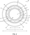
FIG. 2 illustrates a sectioned view of another device configured to remove heat from a core of a nuclear reactor, in accordance with at least one non-limiting aspect of the present disclosure. -
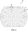
FIG. 3 illustrates a top view of a unit cell including a plurality of devices configured to remove heat from the core of a nuclear reactor, in accordance with at least one non-limiting aspect of the present disclosure. -
FIG. 4 illustrates a side view of a system configured to remove heat from a core of a nuclear reactor, in accordance with at least one non-limiting aspect of the present disclosure. -
FIG. 5 illustrates a side view of another system configured to remove heat from a core of a nuclear reactor, in accordance with at least one non-limiting aspect of the present disclosure. - Corresponding reference characters indicate corresponding parts throughout the several views. The exemplifications set out herein illustrate various aspects of the invention, in one form, and such exemplifications are not to be construed as limiting the scope of the invention in any manner.
- Numerous specific details are set forth to provide a thorough understanding of the overall structure, function, manufacture, and use of the aspects as described in the disclosure and illustrated in the accompanying drawings. Well-known operations, components, and elements have not been described in detail so as not to obscure the aspects described in the specification. The reader will understand that the aspects described and illustrated herein are non-limiting examples, and thus it can be appreciated that the specific structural and functional details disclosed herein may be representative and illustrative. Variations and changes thereto may be made without departing from the scope of the claims. Furthermore, it is to be understood that such terms as "forward", "rearward", "left", "right", "upwardly", "downwardly", and the like are words of convenience and are not to be construed as limiting terms.
- In the following description, like reference characters designate like or corresponding parts throughout the several views of the drawings.
- Before explaining various aspects of the articulated manipulator in detail, it should be noted that the illustrative examples are not limited in application or use to the details of construction and arrangement of parts illustrated in the accompanying drawings and description. The illustrative examples may be implemented or incorporated in other aspects, variations, and modifications, and may be practiced or carried out in various ways. Further, unless otherwise indicated, the terms and expressions employed herein have been chosen for the purpose of describing the illustrative examples for the convenience of the reader and are not for the purpose of limitation thereof. Also, it will be appreciated that one or more of the following-described aspects, expressions of aspects, and/or examples, can be combined with any one or more of the other following-described aspects, expressions of aspects, and/or examples.
- The present disclosure is directed to devices, systems, and methods for removing heat from a nuclear reactor core. The management of thermal energy within a core is important for nuclear reactors. For example, if the core of a nuclear reactor overheats, the reactor may be taken off line for subsequent repair, the usable life of the core can be shortened, and the reactor can become potentially hazardous to operate. The removal of heat from the core of a nuclear reactor becomes even more challenging-and critical-as reactors decrease in size and become more modular.
- Some compact reactors function as a "nuclear battery" which uses energy from the fission of nuclear materials (e.g. uranium) to generate electricity. Accordingly, compact reactors can optimize reactor output while reducing reactor size. However, as the size of the reactor is reduced, it becomes increasingly difficult to remove heat from the system. Thermal management within a compact reactor can be accomplished via a configuration of heat pipes. For example, each heat pipe of a compact reactor can include a small amount of a working fluid (e.g. sodium liquid) configured to move heat from the reactor core to a heat exchanger, where it can be utilized to generate electricity. Unlike traditional reactors-which require a large volume of coolant to be pumped through the core-heat pipe-based reactors require a relatively small amount of working fluid, most of which is contained within the wicks of the heat pipes themselves. Accordingly, heat pipe based reactors do not require mechanical pumps, valves, loop piping, and the associated auxiliary systems required to cool a conventional reactor, which further reduces the size of the overall reactor.
- As such, heat pipe performance and configuration remain a key design consideration for compact reactors. Since the heat pipes streamline the thermal management system by eliminating the need for auxiliary cooling components, the heat pipe configuration itself becomes a constraint for further reductions in reactor size. Conventional heat pipes include a single tube that defines an inner tube volume filled with working fluid, and a heat source and sink positioned external to the conventional heat pipe. Theoretical research regarding the use of concentric, annular heat pipes with a single wick positioned at the inner heat pipe wall has been performed at Newcastle University. Additionally, annular heat pipes are implemented in Isothermal Furnace Liners, not to transport large amount of heat, but to create a uniform temperature distribution for temperature calibration. None of the aforementioned heat pipes have been proven to effectively remove heat from a compact reactor-let alone remove heat efficiently such that the size of the reactor can be further reduced. Accordingly, there is a need for improved heat pipes that can efficiently remove heat from a compact reactor while reducing their size and overall footprint.
- Referring now to
FIG. 1 , a sectioned view of adevice 100 configured to remove heat from the core of a nuclear reactor is depicted in accordance with at least one non-limiting aspect of the present disclosure. For example, thedevice 100 can be a heat pipe configured for implementation within a compact nuclear reactor. According to the non-limiting aspect ofFIG. 1 , theheat pipe 100 can include aninner housing 104 and anouter housing 108. Theinner housing 104 ofFIG. 1 can further include anouter surface 106 positioned within theheat pipe 100 such that it faces aninner surface 110 of theouter housing 108. As can be seen in the non-limiting aspect ofFIG. 1 , theheat pipe 100 can include an annular configuration with a circularouter housing 108 concentrically positioned about a circularinner housing 104. A length of theheat pipe 100 can extend along the centerline about which theinner housing 104 andouter housing 108 are concentrically positioned, thereby forming a tube-like configuration. According to the non-limiting aspect ofFIG. 1 , theinner housing 104 can include an outer diameter D1 less than an inner diameter D2 of theouter housing 108 to achieve the aforementioned annular configuration. However, it shall be appreciated that the non-limiting circularly configured aspect ofFIG. 1 is exclusively presented for illustrative purposes. It shall be appreciated that the term "diameter", as used by the present disclosure, shall include any dimension that extends away from a center point of thedevice 100. As such, it shall be appreciated that the term "diameter" is not intended to limit thedevice 100 to a circular configuration. - Although the non-limiting aspect of
FIG. 1 depicts aheat pipe 100 with circular, concentrically orientedhousings inner housing 104 andouter housing 108. Accordingly, other non-limiting aspects of the present disclosure include aninner housing 104 andouter housing 108 of varying configurations (e.g. square, rectangular, triangular, octagonal). In still other non-limiting aspects, theinner housing 104 can include a first geometric configuration and theouter housing 108 can include a second geometric configuration that is different from the first. For example, theinner housing 104 can include an octagonal configuration and theouter housing 108 can include a circular configuration, such that at least a portion theouter surface 106 of theinner housing 104 is not parallel to a corresponding portion of theinner surface 110 of theouter housing 108. - In further reference to
FIG. 1 , theinner housing 104 can further define avolume 103 configured to accommodate aninternal heat source 102, such that theheat pipe 100 substantially surrounds theheat source 102 when properly inserted within thevolume 103. For example, theheat source 102 can include any material configured to generate thermal energy, such as a fuel source (e.g. uranium nitride) or a moderator (e.g. a hydride-based moderator) of the nuclear reactor. Additionally, when properly inserted within thevolume 103, theheat source 102 can be positioned adjacent to aninner surface 107 of theinner housing 104. According to some non-limiting aspects, theheat source 102 can be in physical contact with theinner surface 107 of theinner housing 104 when properly inserted. According to other non-limiting aspects, thevolume 103 can be filled with an intermediary material configured to enhance heat transfer betweenheat source 102. Regardless, the interface between theheat source 102 and theheat pipe 100 can be configured to efficiently transfer heat away from theheat source 102. - Still referring to
FIG. 1 , theheat pipe 100 can further include awick 112 positioned within theintermediate volume 111 between theinner housing 104 and theouter housing 108. Thewick 112 can be configured to contact at least a portion of theouter surface 106 of theinner housing 104 and at least a portion of theinner surface 110 of theouter housing 108. For example, according to the non-limiting aspect ofFIG. 1 , thewick 112 can include aninner surface 116 positioned in thermal communication with theouter surface 106 of theinner housing 104 and anouter surface 118 positioned in thermal communication with theinner surface 110 of theouter housing 108. In some non-limiting aspects, thesurfaces wick 112 can be configured to mechanically contact thesurfaces housings FIG. 1 , thewick 112 can further include a plurality ofribs 120 mechanically coupled to at least a portion of theinner surface 116 andouter surface 118 of thewick 112. The plurality ofribs 120 can include either the same or a similar wicking material to thewick 112. However, according to other non-limiting aspects, theribs 120 can be configured to directly contact thesurfaces housings ribs 120 depicted inFIG. 1 extend radially outward from the center of the concentrically oriented inner andouter housing ribs 120 are oriented in any number of varying configurations (e.g. zig-zag, circular, cruciform). - According to the non-limiting aspect of
FIG. 1 , a working fluid (e.g. sodium liquid) can be positioned within theintermediate volume 111 of theheat pipe 100 and thewick 112 can be composed of one or more materials that include capillary properties (e.g. any porous material). Theheat pipe 100 can be positioned within the nuclear reactor such that one of its ends is positioned within a condenser of the nuclear reactor. As such, working fluid that has condensed on a cold side of theheat pipe 100 can be returned to a hot side of theheat pipe 100 for evaporation due to the capillary properties of thewick 112, thereby renewing the heat transfer cycle. In other words, theheat pipe 100 ofFIG. 1 can be configured to remove heat from theheat source 102 positioned within theheat pipe 100. It shall be appreciated that the integration of theheat source 102,inner housing 104,outer housing 108, and wick 112-when properly positioned relative to and evaporator and condenser of the nuclear reactor-can facilitate the efficient transfer of thermal energy away from the core of the nuclear reactor. Accordingly, theheat pipe 100 ofFIG. 1 can more efficiently manage the thermal energy produced by a compact nuclear reactor when compared to known single-tube heat pipe configurations. This can result in improved performance and reliability and result in compact reactors of reduced size. - Referring now to
FIG. 2 , a sectioned view of anotherdevice 200 configured to remove heat from a core of a nuclear reactor is depicted in accordance with at least one non-limiting aspect of the present disclosure. According to the non-limiting aspect ofFIG. 2 , thedevice 200 can be similarly configured to theheat pipe 100 ofFIG. 1 . For example, thedevice 200 can include a heat pipe configured for implementation within a nuclear reactor, with aninner housing 204 and anouter housing 208. Similar to theheat pipe 100 ofFIG. 1 , theinner housing 204 ofFIG. 2 can include anouter surface 206 positioned within theheat pipe 200 such that it faces aninner surface 210 of theouter housing 208. Again, theheat pipe 200 can include an annular configuration with a circularouter housing 208 concentrically positioned about a circularinner housing 204, and theheat pipe 200 once again extends in a tube-like configuration. However, the annular configuration ofFIG. 2 is intended for illustrative purposes only. Accordingly, in other non-limiting aspects, theheat pipe 200 can include any number of geometrical configurations (e.g. square, rectangular, triangular, octagonal). Regardless, theinner housing 204 can define avolume 203 configured to accommodate aninternal heat source 202. - In further reference to the non-limiting aspect of
FIG. 2 , theheat pipe 200 can further include acladding layer 222 concentrically oriented about theheat source 202, theinner housing 204, and theouter housing 208. Thecladding layer 222 can include a cladding diameter D3 that is greater than the inner diameter D1 and the outer diameter D1, such that thecladding 222 substantially surrounds the components of theheat pipe 200 that were discussed in reference to theheat pipe 100 ofFIG. 1 . Although thecladding 222 ofFIG. 2 includes a circular configuration, it too can include any number of different geometrical configurations, even if theinner housing 204 andouter housing 208 are circular. Regardless, thecladding layer 222 can define a secondintermediate volume 217 between aninner surface 226 of thecladding layer 222 and anouter surface 224 of theouter housing 208. For example, thecladding layer 222 can include a thin-walled tube made of a material configured to contain any nuclear material positioned within theheat pipe 200. Accordingly, thecladding layer 222 can be specifically configured to prevent the corrosion of the and thus, prevent the release of detrimental and potentially hazardous materials into an operating environment. - Still referring to
FIG. 2 , theheat pipe 200 can further include awick 212 positioned within anintermediate volume 211 defined between theinner housing 204 and theouter housing 208. Thewick 212 can be configured to contact at least a portion of theouter surface 206 of theinner housing 204 and at least a portion of theinner surface 210 of theouter housing 208. For example, according to the non-limiting aspect ofFIG. 2 , thewick 212 can include aninner surface 216 positioned in thermal communication with theouter surface 206 of theinner housing 204 and anouter surface 218 positioned in thermal communication with theinner surface 210 of theouter housing 208. In some non-limiting aspects, thesurfaces wick 212 can be configured to mechanically contact thesurfaces housings FIG. 2 , thewick 212 can further include a plurality ofribs 220 mechanically coupled to at least a portion of theinner surface 216 andouter surface 218 of thewick 212. The plurality ofribs 220 can include either the same or a similar wicking material to thewick 212. However, according to other non-limiting aspects, theribs 220 can be configured to directly contact thesurfaces housings - Although the
ribs 220 depicted inFIG. 2 extend radially outward from the center of the concentrically oriented inner andouter housing ribs 220 are oriented in any number of varying configurations (e.g. zig-zag, circular, cruciform). - According to the non-limiting aspect of
FIG. 2 , a working fluid (e.g. sodium liquid, and/or the like) can be positioned within theintermediate volume 211 of theheat pipe 200 and thewick 212 can be composed of one or more materials that include capillary properties (e.g. any porous material). Theheat pipe 200 can be positioned within the nuclear reactor such that one of its ends is positioned within a condenser of the nuclear reactor. As such, working fluid that has condensed on a cold side of theheat pipe 200 can be returned to a hot side of theheat pipe 200 for evaporation due to the capillary properties of thewick 212, thereby renewing the heat transfer cycle. In other words, theheat pipe 200 ofFIG. 2 can be configured to remove heat away from theheat source 202 positioned within theheat pipe 200. It shall be appreciated that the integration of theheat source 202,inner housing 204,outer housing 208, and wick 212-when properly positioned relative to and evaporator and condenser of the nuclear reactor-can facilitate the efficient transfer of thermal energy away from the core of the nuclear reactor. Accordingly, theheat pipe 200 ofFIG. 2 can more efficiently manage the thermal energy produced by a compact nuclear reactor when compared to known single-tube heat pipe configurations. This can result in improved performance and reliability and result in compact reactors of reduced size. - According to the non-limiting aspect of
FIG. 2 , theheat pipe 200 ofFIG. 2 can include a moderator-type 202 heat source (e.g. hydride-based moderator, and/or the like) positioned within thevolume 203, and a fuel 228 (e.g. uranium nitride, and/or the like) positioned within the secondintermediate volume 217, as defined by thecladding layer 222. Accordingly, themoderator 202 can be surrounded by thewick 212 of theannular heat pipe 200 and thewick 212 of theannular heat pipe 200 can be surrounded by theannular fuel 228. As such, theheat pipe 200 ofFIG. 2 can includemultiple heat sources heat pipe 200 failure,adjacent heat pipes 200 can compensate for the failure by transferring excess heat away from the core. - Although the non-limiting aspects of
FIGS. 1 and2 includeheat pipes integrated heat sources heat pipes heat sources wick 212 of theheat pipe 200 ofFIG. 2 can be surrounded by aheat source 202, depending on whether the intended application and/or user preference can accommodate for the less efficient use of space. In still other non-limiting aspects, thefuel 228 can be surrounded by thewick 212 of theheat pipe 200 ofFIG. 2 and themoderator 202 can be configured to surround thewick 212 of theheat pipe 200. In other words, the position of thefuel 228 andmoderator 202 ofFIG. 2 can be inverted, depending on whether the intended application and/or user preference can accommodate for less efficient cooling in the event of heat pipe failure. In both aspects, the user might be motivated to optimize other variables at the expense of nuclear reactor size and/or efficiency of heat transfer, which provides theheat pipe 200 design ofFIG. 2 with a certain degree of customization. Ultimately, optimization of theheat pipe 200 design depends on the intended application and/or user preference for the nuclear reactor design, both of which are increasing in importance due to the emergence of micro-reactors. - Referring now to
FIG. 3 , a top view of aunit cell 300 including a plurality ofdevices 302 configured to remove heat from the core of a nuclear reactor is depicted in accordance with at least one non-limiting aspect of the present disclosure. It shall be appreciated that, although theunit cell 300 ofFIG. 3 includes 19devices 302, the present disclosure contemplates other non-limiting aspects wherein theunit cell 300 includes any number ofdevices 302. Additionally and/or alternatively, the hexagonal configuration of theunit cell 300 ofFIG. 3 is exclusively presented for illustrative purposes. As such, it shall be appreciated that theunit cell 300 ofFIG. 3 can include any number of geometric configurations, depending on the desired output and thermal properties of the core. - According to the non-limiting aspect of
FIG. 3 , eachdevice 302 of the plurality ofdevices 302 can be configured to substantially surround anintegrated heat source 304 of the core. Theheat source 304 can include either a fuel rod, a moderator, or combinations therefor. As was discussed in reference toFIGS. 1 and2 , eachdevice 302 of the plurality ofdevices 302 can further include anassembly 306 configured to surround theintegrated heat source 304. Theassembly 306 can include any of the features discussed in reference toFIGS. 1 and2 , including awick heat pipe ribs heat source 304. According to some non-limiting aspects, theassembly 306 can further include acladding 222 that defines a secondintermediate volume 217 configured to accommodate afuel 228, as discussed in reference toFIG. 2 . In still other non-limiting aspects, eachdevice 302 of the plurality ofdevices 302 can include a different configuration. For example, afirst device 302 can include thedevice 100 configuration ofFIG. 1 and asecond device 302 can include thedevice 200 configuration ofFIG. 2 . - Still referring to
FIG. 3 , eachdevice 302 of theunit cell 300 can be particularly arranged to be adjacent to a number ofother devices 302.Adjacent devices 302 can be positioned at a predetermined distance from one another, such that thermal energy generated by theintegrated heat sources 304 of any givendevice 302 can be effectively transferred away from the core in the event of a heat pipe failure. Since conventional heat pipes are typically surrounded by the heat sources they are intended to cool, adjacent heat pipes are limited in their ability assist in mitigating temperature increases if a first heat pipe fails. Accordingly,unit cell 300 configuration ofFIG. 3 offers a significant improvement and benefit over known devices. Additionally and/or alternatively, theunit cell 300 can include a core block including a material with preferable thermal properties (e.g. graphite) and one or more temperature sensors configured to monitor an operating temperature of theunit cell 300 can be positioned throughout the core of the nuclear reactor. Accordingly, if a heat pipe fails, heat from the integratedheat source 304 can be transferred through the material. The temperature sensors can detect the increase in temperature and determine whether or not it meets or exceeds a predetermined threshold, after which a nuclear reactor shutdown protocol can be commenced. - Referring now to
FIG. 4 , a side view of asystem 400 configured to remove heat from a core of a nuclear reactor is depicted in accordance with at least one non-limiting aspect of the present disclosure. According to the non-limiting aspect ofFIG. 4 , thesystem 400 includes a horizontally oriented device, such as aheat pipe 401, integrated with acondenser 404 of the nuclear reactor. Theheat pipe 401 is configured about aheat source 402, such as fuel or a moderator, the length of which defines an evaporating section of theheat pipe 401, which operates at an evaporating temperature T e . Theheat pipe 401 can further include one or moreinternal end caps 408, one of which defines an adiabatic section of theheat pipe 401 that operates at an adiabatic temperature T sat . According to some non-limiting aspects, theheat pipe 401 can further include acover gas 410 positioned within the adiabatic section. Theheat pipe 401 can terminate in thecondenser 404 of the nuclear reactor, which operates at a condensing temperature T c . According to the non-limiting aspect ofFIG. 4 , the evaporating temperature T e is greater than the adiabatic temperature T sat and the adiabatic temperature T sat is greater than the condensing temperature T c . Collectively, the evaporating section, the adiabatic section, and the condensing section of theheat pipe 401 can constitute a length L of theheat pipe 401. Accordingly, a workingfluid 416 within theheat pipe 401 can evaporate from the heat generated by the integratedheat source 402, travel the length of theheat pipe 401 through the adiabatic section to thecondenser 404, where it is cooled and condenses. The system 400-and more specifically, the heat pipe 401-can be configured to accommodate a small excess of workingfluid 418 proximal the condenser to prevent dry out of theheat pipe 401 and its components. - Notably, the
heat pipe 401 ofFIG. 4 can includeexternal end caps 406, as well as a firstexternal wick 412 and a secondinternal wick 414. Either theexternal end caps 406, theinternal end caps 408, or both can connect theexternal wick 412 and theinternal wick 414. Alternatively and/or additionally, one or more ribs (e.g. theribs devices FIGS. 1 and2 ) can also be configured to connect anexternal wick 412 andinternal wick 414 of theheat pipe 401. Regardless, theexternal wick 412 andinternal wick 414 can cooperate to connect the multiple surfaces of theheat pipe 401, which creates a larger surface area for conduction and convection. Additionally, the connection of theexternal wick 412 and theinternal wick 414 can establish a common volume of theheat pipe 401, while retaining its discrete sections and operating temperatures. This connection can be positioned on a condenser side of theheat pipe 401 for the horizontally configuredsystem 500 ofFIG. 5 . However, It shall be appreciated that theheat pipe 401 with an integral heat source and/or moderator can provide the foregoing benefits with and withoutwicks FIG. 5 . - Referring now to
FIG. 5 , a side view of anothersystem 500 configured to remove heat from a core of a nuclear reactor is depicted in accordance with at least one non-limiting aspect of the present disclosure. According to the non-limiting aspect ofFIG. 5 , thesystem 500 includes a vertically oriented device, such as aheat pipe 501, integrated with acondenser 504 of the nuclear reactor. Thesystem 500 is similarly configured to thesystem 400 ofFIG. 4 . However, thesystem 500 ofFIG. 5 is vertically configured and thus, can operate like a thermosiphon for moving the workingfluid 516. Theheat pipe 501 is configured about aheat source 502, such as fuel or a moderator, the length of which defines an evaporating section of theheat pipe 501, which operates at an evaporating temperature T e . Theheat pipe 501 can further include one or moreinternal end caps 508, one of which defines an adiabatic section of theheat pipe 501 that operates at an adiabatic temperature T sat . According to some non-limiting aspects, theheat pipe 501 can further include a cover gas positioned within the adiabatic section. Theheat pipe 501 can terminate in thecondenser 504 of the nuclear reactor, which operates at a condensing temperature T c . Collectively, the evaporating section, the adiabatic section, and the condensing section of theheat pipe 501 can constitute a length L of theheat pipe 501. According to the non-limiting aspect ofFIG. 5 , the evaporating temperature T e is greater than the adiabatic temperature T sat and the adiabatic temperature T sat is greater than the condensing temperature T c . Accordingly, a workingfluid 516 within theheat pipe 501 can evaporate from the heat generated by the integratedheat source 502, travel the length of theheat pipe 501 through the adiabatic section to thecondenser 504, where it is cooled and condenses. - In further reference to
FIG. 5 , theheat pipe 501 can includeexternal end caps 506. However, according to the non-limiting aspect ofFIG. 5 , the heat pipe can include awicking feature 512 exclusively positioned within the evaporating section. For example, thewicking feature 512 can include either grooves, a partial wick, and/or the like. For the vertical configuration ofFIG. 5 , the heat pipe does not require as many wicking features 412, 414 as the horizontally configuredsystem 400 ofFIG. 4 . This is because gravity can assist in returning condensed workingfluid 516 to the evaporator, although the vertically configuredsystem 500 ofFIG. 5 may not be ideal for high power reactors. - Once again, either the
external end caps 506, theinternal end caps 508, or both can connect the wicking features 512 of theheat pipe 501 ofFIG. 5 . Alternatively and/or additionally, one or more ribs (e.g. theribs devices FIGS. 1 and2 ) can be configured to connect the wicking features 512 of theheat pipe 501. Regardless, the wicking features 512 can cooperate to connect the multiple surfaces of theheat pipe 501, which creates a larger surface area for conduction and convection. Additionally, the connection of the wicking features 512 can establish a common volume of theheat pipe 501, while retaining its discrete sections and operating temperatures. Accordingly, theheat pipe 501 can provide the foregoing benefits with reduced wicking features 512 and can function, even when vertically oriented, to move the workingfluid 516 within the heat pipe 501 (e.g., a thermosiphon). - The present invention has been described with reference to various exemplary and illustrative aspects. The aspects described herein are understood as providing illustrative features of varying detail of various aspects of the disclosed invention; and therefore, unless otherwise specified, it is to be understood that, to the extent possible, one or more features, elements, components, constituents, ingredients, structures, modules, and/or aspects of the disclosed aspects may be combined, separated, interchanged, and/or rearranged with or relative to one or more other features, elements, components, constituents, ingredients, structures, modules, and/or aspects of the disclosed aspects without departing from the scope of the disclosed invention. Accordingly, it will be recognized by persons having ordinary skill in the art that various substitutions, modifications or combinations of any of the exemplary aspects may be made without departing from the scope of the invention. In addition, persons skilled in the art will recognize, or be able to ascertain using no more than routine experimentation, many equivalents to the various aspects of the invention described herein upon review of this specification. Thus, the invention is not limited by the description of the various aspects, but rather by the claims.
- It is worthy to note that any reference to "one aspect," "an aspect," "an exemplification," "one exemplification," and the like means that a particular feature, structure, or characteristic described in connection with the aspect is included in at least one aspect. Thus, appearances of the phrases "in one aspect," "in an aspect," "in an exemplification," and "in one exemplification" in various places throughout the specification are not necessarily all referring to the same aspect. Furthermore, the particular features, structures or characteristics may be combined in any suitable manner in one or more aspects.
- Directional phrases used herein, such as, for example and without limitation, top, bottom, left, right, lower, upper, front, back, and variations thereof, shall relate to the orientation of the elements as shown in the accompanying drawing.
- The terms "comprise" (and any form of comprise, such as "comprises" and "comprising"), "have" (and any form of have, such as "has" and "having"), "include" (and any form of include, such as "includes" and "including") and "contain" (and any form of contain, such as "contains" and "containing") are open-ended linking verbs. As a result, a system that "comprises," "has," "includes" or "contains" one or more elements possesses those one or more elements, but is not limited to possessing only those one or more elements. Likewise, an element of a system, device, or apparatus that "comprises," "has," "includes" or "contains" one or more features possesses those one or more features, but is not limited to possessing only those one or more features.
Claims (12)
- A heat pipe configured to remove heat from a core of a nuclear reactor, the heat pipe comprising:an inner housing defining an inner volume configured to accommodate a heat source;an outer housing configured about the inner housing and the heat source;a wick positioned between at least a portion of the inner housing and at least a portion of the outer housing, wherein the wick comprises a capillary material, and wherein the wick defines an intermediate volume between the inner housing and the outer housing; anda working fluid within the intermediate volume, wherein the working fluid is configured to evaporate at a first end of the heat pipe, wherein the working fluid is further configured to condense at a second end of the heat pipe adjacent to a heat exchanger, and wherein the wick is configured to return working fluid that has condensed at the second end of the heat pipe to the first end of the heat pipe.
- The heat pipe of claim 1, wherein the wick comprises a plurality of ribs, wherein at least a first rib of the plurality of ribs contacts at least a portion of the inner housing, and wherein at least a second rib of the plurality of ribs contacts at least a portion of the outer housing.
- The heat pipe of claim 2, wherein the heat pipe comprises a tube configuration, wherein the outer housing and the inner housing each comprise a circular configuration, wherein the outer housing is concentrically oriented about the inner housing, and wherein the plurality of ribs are configured to extend radially from a center point of the inner housing.
- The heat pipe of claim 1, whereinthe heat pipe comprises a length;the inner housing comprises an outer surface;the outer housing comprises an inner surface;the wick extends along at least a portion of the length of the heat pipe, wherein the wick is configured to contact at least a portion of the outer surface of the inner housing, wherein the wick is configured to contact at least a portion of the inner surface of the outer housing; andthe evaporation and condensation of the working fluid is configured to transfer heat from the first end of the heat pipe to the second end of the heat pipe for dissipation via a heat exchanger.
- The heat pipe of claim 4, wherein the wick comprises a plurality of ribs, wherein at least a first rib of the plurality of ribs contacts at least a portion of the outer surface of the inner housing, and wherein at least a second rib of the plurality of ribs contacts at least a portion of the inner surface of the outer housing.
- The heat pipe of claim 5, wherein the heat pipe comprises a tube configuration, wherein the outer housing and the inner housing each comprise a circular configuration, wherein the outer housing is concentrically oriented about the inner housing, and wherein the plurality of ribs are configured to extend radially from a center point of the inner housing.
- The heat pipe of any one of claims 4 to 6, further comprising an end-cap coupled to the second end of the heat pipe, wherein the second end-cap is configured to mechanically contact the outer housing, the inner housing, and the wick, thereby establishing a thermal circuit that traverses through the inner volume and intermediary volume.
- The heat pipe of any one of claims 4 to 7, wherein the heat source is a moderator comprising a hydride.
- The heat pipe of any one of claims 4 to 8, wherein the heat source is a nuclear fuel.
- The heat pipe of any one of claims 4 to 9, wherein the heat source is a moderator, and wherein the heat pipe further comprises a cladding configured about the outer housing, wherein the cladding defines a second intermediary volume about the outer housing, and wherein a nuclear fuel is positioned within the second intermediary volume.
- The heat pipe of any one of claims 4 to 10, further comprising a reservoir positioned at the second end of the heat pipe, wherein the reservoir is configured to contain an excess amount of working fluid, and wherein the excess amount of working fluid is configured to prevent the heat pipe and its components from drying out.
- The heat pipe of any one of claims 4 to 11, wherein the heat pipe further comprises a vertically oriented thermosiphon configured such that gravity at least partially assists the wick in returning working fluid that has condensed at the second end of the heat pipe to the first end of the heat pipe.
Applications Claiming Priority (3)
| Application Number | Priority Date | Filing Date | Title |
|---|---|---|---|
| US17/084,440 US11955249B2 (en) | 2020-10-29 | 2020-10-29 | Heat pipe having a wick between concentric inner and outer housings, for use in heat removal from a nuclear reactor core |
| EP21831464.9A EP4252256B1 (en) | 2020-10-29 | 2021-10-29 | Devices, systems, and methods for removing heat from a nuclear reactor core |
| PCT/US2021/072105 WO2022094593A1 (en) | 2020-10-29 | 2021-10-29 | Devices, systems, and methods for removing heat from a nuclear reactor core |
Related Parent Applications (2)
| Application Number | Title | Priority Date | Filing Date |
|---|---|---|---|
| EP21831464.9A Division EP4252256B1 (en) | 2020-10-29 | 2021-10-29 | Devices, systems, and methods for removing heat from a nuclear reactor core |
| EP21831464.9A Division-Into EP4252256B1 (en) | 2020-10-29 | 2021-10-29 | Devices, systems, and methods for removing heat from a nuclear reactor core |
Publications (2)
| Publication Number | Publication Date |
|---|---|
| EP4325157A2 true EP4325157A2 (en) | 2024-02-21 |
| EP4325157A3 EP4325157A3 (en) | 2024-04-24 |
Family
ID=79092981
Family Applications (2)
| Application Number | Title | Priority Date | Filing Date |
|---|---|---|---|
| EP21831464.9A Active EP4252256B1 (en) | 2020-10-29 | 2021-10-29 | Devices, systems, and methods for removing heat from a nuclear reactor core |
| EP23215096.1A Pending EP4325157A3 (en) | 2020-10-29 | 2021-10-29 | Devices, systems, and methods for removing heat from a nuclear reactor core |
Family Applications Before (1)
| Application Number | Title | Priority Date | Filing Date |
|---|---|---|---|
| EP21831464.9A Active EP4252256B1 (en) | 2020-10-29 | 2021-10-29 | Devices, systems, and methods for removing heat from a nuclear reactor core |
Country Status (8)
| Country | Link |
|---|---|
| US (2) | US11955249B2 (en) |
| EP (2) | EP4252256B1 (en) |
| JP (2) | JP7755918B2 (en) |
| KR (1) | KR20230098254A (en) |
| CA (1) | CA3196896A1 (en) |
| ES (1) | ES2993308T3 (en) |
| TW (2) | TWI836702B (en) |
| WO (1) | WO2022094593A1 (en) |
Families Citing this family (4)
| Publication number | Priority date | Publication date | Assignee | Title |
|---|---|---|---|---|
| FR3123114B1 (en) * | 2021-05-20 | 2023-07-14 | Euro Heat Pipes | Improved performance heat pipe under various thermal load distributions |
| US20240021327A1 (en) * | 2022-07-12 | 2024-01-18 | BWXT Advanced Technologies LLC | Heat pipe fuel element and fission reactor incorporating same, particularly having phyllotaxis spacing pattern of heat pipe fuel elements, and method of manufacture |
| US12196496B2 (en) * | 2022-09-25 | 2025-01-14 | Aic Inc. | Liquid-cooled cooling structure |
| US12305929B2 (en) * | 2023-02-06 | 2025-05-20 | Westinghouse Electric Company Llc | Advanced manufacturing heat pipe segment with integral printed wick |
Citations (3)
| Publication number | Priority date | Publication date | Assignee | Title |
|---|---|---|---|---|
| US3414475A (en) | 1965-05-20 | 1968-12-03 | Euratom | Heat pipes |
| US5000252A (en) | 1990-02-22 | 1991-03-19 | Wright State University | Thermal energy storage system |
| US10559389B2 (en) | 2017-02-06 | 2020-02-11 | Battell Energy Alliance, LLC | Modular nuclear reactors including fuel elements and heat pipes extending through grid plates, and methods of forming the modular nuclear reactors |
Family Cites Families (13)
| Publication number | Priority date | Publication date | Assignee | Title |
|---|---|---|---|---|
| JP3109917B2 (en) * | 1992-09-07 | 2000-11-20 | 学校法人東海大学 | Decay heat removal system for nuclear reactor |
| KR100419318B1 (en) * | 2000-12-07 | 2004-02-19 | 한국전력공사 | Decay heat removal apparatus using the thermosyphon in the liquid metal reactor |
| US6768781B1 (en) * | 2003-03-31 | 2004-07-27 | The Boeing Company | Methods and apparatuses for removing thermal energy from a nuclear reactor |
| US8000431B2 (en) * | 2008-11-20 | 2011-08-16 | Hamilton Sundstrad Corporation | Method and composition for moderated nuclear fuel |
| US8811562B2 (en) | 2010-03-12 | 2014-08-19 | Babcock & Wilcox Nuclear Operations Group, Inc. | Control rod drive mechanism for nuclear reactor |
| US20130156143A1 (en) | 2011-12-14 | 2013-06-20 | Billy E. Bingham | Emergency core cooling system (eccs) for nuclear reactor employing closed heat transfer pathways |
| JP2015072223A (en) | 2013-10-03 | 2015-04-16 | Nine Star Holding Japan株式会社 | Nuclear reactor |
| US20160329113A1 (en) | 2013-12-06 | 2016-11-10 | Stc.Unm | SLIMM-Scalable Liquid Metal Cooled Small Modular Reactor |
| JP5838511B2 (en) | 2014-03-25 | 2016-01-06 | 株式会社 シー・アール・ワイ | Reactor |
| JP6633471B2 (en) | 2016-08-01 | 2020-01-22 | 株式会社東芝 | REACTOR AND HEAT REMOVAL METHOD FOR REACTOR |
| JP6716479B2 (en) | 2017-02-21 | 2020-07-01 | 株式会社東芝 | Emergency core cooling system and boiling water nuclear power plant using the same |
| WO2019133398A1 (en) | 2017-12-29 | 2019-07-04 | Nuscale Power, Llc | Nuclear reactor module with a cooling chamber for a drive motor of a control rod drive mechanism |
| RU2687288C1 (en) * | 2018-08-16 | 2019-05-13 | Акционерное общество "Государственный научный центр Российской Федерации - Физико-энергетический институт имени А.И. Лейпунского" | Nuclear reactor active zone |
-
2020
- 2020-10-29 US US17/084,440 patent/US11955249B2/en active Active
-
2021
- 2021-10-29 TW TW111142266A patent/TWI836702B/en active
- 2021-10-29 TW TW110140315A patent/TWI803036B/en active
- 2021-10-29 WO PCT/US2021/072105 patent/WO2022094593A1/en not_active Ceased
- 2021-10-29 EP EP21831464.9A patent/EP4252256B1/en active Active
- 2021-10-29 EP EP23215096.1A patent/EP4325157A3/en active Pending
- 2021-10-29 CA CA3196896A patent/CA3196896A1/en active Pending
- 2021-10-29 KR KR1020237017819A patent/KR20230098254A/en active Pending
- 2021-10-29 JP JP2023526470A patent/JP7755918B2/en active Active
- 2021-10-29 ES ES21831464T patent/ES2993308T3/en active Active
-
2024
- 2024-04-01 US US18/623,667 patent/US20240274306A1/en active Pending
-
2025
- 2025-10-05 JP JP2025167781A patent/JP2026009997A/en active Pending
Patent Citations (3)
| Publication number | Priority date | Publication date | Assignee | Title |
|---|---|---|---|---|
| US3414475A (en) | 1965-05-20 | 1968-12-03 | Euratom | Heat pipes |
| US5000252A (en) | 1990-02-22 | 1991-03-19 | Wright State University | Thermal energy storage system |
| US10559389B2 (en) | 2017-02-06 | 2020-02-11 | Battell Energy Alliance, LLC | Modular nuclear reactors including fuel elements and heat pipes extending through grid plates, and methods of forming the modular nuclear reactors |
Also Published As
| Publication number | Publication date |
|---|---|
| JP2023548333A (en) | 2023-11-16 |
| ES2993308T3 (en) | 2024-12-26 |
| US20220139581A1 (en) | 2022-05-05 |
| TWI836702B (en) | 2024-03-21 |
| EP4325157A3 (en) | 2024-04-24 |
| US11955249B2 (en) | 2024-04-09 |
| TWI803036B (en) | 2023-05-21 |
| CA3196896A1 (en) | 2022-05-05 |
| EP4252256A1 (en) | 2023-10-04 |
| TW202324451A (en) | 2023-06-16 |
| JP2026009997A (en) | 2026-01-21 |
| US20240274306A1 (en) | 2024-08-15 |
| KR20230098254A (en) | 2023-07-03 |
| JP7755918B2 (en) | 2025-10-17 |
| TW202236304A (en) | 2022-09-16 |
| WO2022094593A1 (en) | 2022-05-05 |
| EP4252256B1 (en) | 2024-08-28 |
Similar Documents
| Publication | Publication Date | Title |
|---|---|---|
| EP4252256B1 (en) | Devices, systems, and methods for removing heat from a nuclear reactor core | |
| US11476011B2 (en) | Reactor core having both nuclear fuel and a heat pipe in a module located in a solid neutron moderator | |
| US20180033501A1 (en) | Nuclear reactor and a method of heat transfer from a core | |
| US3302042A (en) | Nuclear reactor with thermionic converter | |
| RU2680250C1 (en) | Active zone of the nuclear reactor | |
| US8253008B2 (en) | AMTEC with heat pipe | |
| CN104766636B (en) | A kind of nuclear fuel rod cools down the nested integral structure of heat pipe with center | |
| CN108511092A (en) | A kind of integral structure that nuclear fuel element is nested with circuit parallel type cooling heat pipe | |
| CN102568623B (en) | Fast neutron reactor and alkali metal thermoelectric converter integrated device for exoplanet | |
| RU2660942C1 (en) | Active zone of the nuclear reactor | |
| JP2007033128A (en) | Liquid metal cooled nuclear reactor with alkali metal thermoelectric generator | |
| KR101494372B1 (en) | The apparatus of bubble jet heat pipe in cooling system of spent fuel pool | |
| JP2021179313A (en) | Nuclear reactor and heat removal method for nuclear reactor | |
| CN204614458U (en) | A kind of nuclear fuel rod and center cool the nested integral structure of heat pipe | |
| CN118336020A (en) | Submerged liquid cooling thermal management system for fuel cell | |
| CN117514514A (en) | Nuclear power supply and its cooling components | |
| CN115223736B (en) | An underground nuclear power source | |
| US20260118068A1 (en) | Passive Thermal Energy Transport and Energy Conversion Methods for SLIMM Small Modular Reactor | |
| CN120260990A (en) | A hexagonal ring heat pipe cooling reactor | |
| BR112019028262B1 (en) | REACTOR CORE | |
| BR112019028207B1 (en) | ACTIVE AREA OF A NUCLEAR REACTOR |
Legal Events
| Date | Code | Title | Description |
|---|---|---|---|
| PUAI | Public reference made under article 153(3) epc to a published international application that has entered the european phase |
Free format text: ORIGINAL CODE: 0009012 |
|
| STAA | Information on the status of an ep patent application or granted ep patent |
Free format text: STATUS: THE APPLICATION HAS BEEN PUBLISHED |
|
| AC | Divisional application: reference to earlier application |
Ref document number: 4252256 Country of ref document: EP Kind code of ref document: P |
|
| AK | Designated contracting states |
Kind code of ref document: A2 Designated state(s): AL AT BE BG CH CY CZ DE DK EE ES FI FR GB GR HR HU IE IS IT LI LT LU LV MC MK MT NL NO PL PT RO RS SE SI SK SM TR |
|
| REG | Reference to a national code |
Ref country code: DE Ref legal event code: R079 Free format text: PREVIOUS MAIN CLASS: F28D0015020000 Ipc: G21C0015257000 |
|
| PUAL | Search report despatched |
Free format text: ORIGINAL CODE: 0009013 |
|
| AK | Designated contracting states |
Kind code of ref document: A3 Designated state(s): AL AT BE BG CH CY CZ DE DK EE ES FI FR GB GR HR HU IE IS IT LI LT LU LV MC MK MT NL NO PL PT RO RS SE SI SK SM TR |
|
| RIC1 | Information provided on ipc code assigned before grant |
Ipc: F28D 21/00 20060101ALN20240318BHEP Ipc: F28D 15/04 20060101ALI20240318BHEP Ipc: F28D 15/02 20060101ALI20240318BHEP Ipc: G21C 15/257 20060101AFI20240318BHEP |
|
| STAA | Information on the status of an ep patent application or granted ep patent |
Free format text: STATUS: REQUEST FOR EXAMINATION WAS MADE |
|
| 17P | Request for examination filed |
Effective date: 20241023 |
|
| RBV | Designated contracting states (corrected) |
Designated state(s): AL AT BE BG CH CY CZ DE DK EE ES FI FR GB GR HR HU IE IS IT LI LT LU LV MC MK MT NL NO PL PT RO RS SE SI SK SM TR |
|
| STAA | Information on the status of an ep patent application or granted ep patent |
Free format text: STATUS: EXAMINATION IS IN PROGRESS |
|
| 17Q | First examination report despatched |
Effective date: 20260313 |