EP4325113A1 - Beleuchtungsvorrichtung für einen kraftfahrzeugscheinwerfer - Google Patents
Beleuchtungsvorrichtung für einen kraftfahrzeugscheinwerfer Download PDFInfo
- Publication number
- EP4325113A1 EP4325113A1 EP22190799.1A EP22190799A EP4325113A1 EP 4325113 A1 EP4325113 A1 EP 4325113A1 EP 22190799 A EP22190799 A EP 22190799A EP 4325113 A1 EP4325113 A1 EP 4325113A1
- Authority
- EP
- European Patent Office
- Prior art keywords
- lighting device
- light distribution
- edge
- aperture
- diaphragm
- Prior art date
- Legal status (The legal status is an assumption and is not a legal conclusion. Google has not performed a legal analysis and makes no representation as to the accuracy of the status listed.)
- Granted
Links
Images


Classifications
-
- F—MECHANICAL ENGINEERING; LIGHTING; HEATING; WEAPONS; BLASTING
- F21—LIGHTING
- F21S—NON-PORTABLE LIGHTING DEVICES; SYSTEMS THEREOF; VEHICLE LIGHTING DEVICES SPECIALLY ADAPTED FOR VEHICLE EXTERIORS
- F21S41/00—Illuminating devices specially adapted for vehicle exteriors, e.g. headlamps
- F21S41/40—Illuminating devices specially adapted for vehicle exteriors, e.g. headlamps characterised by screens, non-reflecting members, light-shielding members or fixed shades
- F21S41/43—Illuminating devices specially adapted for vehicle exteriors, e.g. headlamps characterised by screens, non-reflecting members, light-shielding members or fixed shades characterised by the shape thereof
-
- B—PERFORMING OPERATIONS; TRANSPORTING
- B60—VEHICLES IN GENERAL
- B60Q—ARRANGEMENT OF SIGNALLING OR LIGHTING DEVICES, THE MOUNTING OR SUPPORTING THEREOF OR CIRCUITS THEREFOR, FOR VEHICLES IN GENERAL
- B60Q1/00—Arrangement of optical signalling or lighting devices, the mounting or supporting thereof or circuits therefor
- B60Q1/02—Arrangement of optical signalling or lighting devices, the mounting or supporting thereof or circuits therefor the devices being primarily intended to illuminate the way ahead or to illuminate other areas of way or environments
- B60Q1/04—Arrangement of optical signalling or lighting devices, the mounting or supporting thereof or circuits therefor the devices being primarily intended to illuminate the way ahead or to illuminate other areas of way or environments the devices being headlights
-
- F—MECHANICAL ENGINEERING; LIGHTING; HEATING; WEAPONS; BLASTING
- F21—LIGHTING
- F21S—NON-PORTABLE LIGHTING DEVICES; SYSTEMS THEREOF; VEHICLE LIGHTING DEVICES SPECIALLY ADAPTED FOR VEHICLE EXTERIORS
- F21S41/00—Illuminating devices specially adapted for vehicle exteriors, e.g. headlamps
- F21S41/10—Illuminating devices specially adapted for vehicle exteriors, e.g. headlamps characterised by the light source
- F21S41/14—Illuminating devices specially adapted for vehicle exteriors, e.g. headlamps characterised by the light source characterised by the type of light source
- F21S41/141—Light emitting diodes [LED]
- F21S41/143—Light emitting diodes [LED] the main emission direction of the LED being parallel to the optical axis of the illuminating device
-
- F—MECHANICAL ENGINEERING; LIGHTING; HEATING; WEAPONS; BLASTING
- F21—LIGHTING
- F21S—NON-PORTABLE LIGHTING DEVICES; SYSTEMS THEREOF; VEHICLE LIGHTING DEVICES SPECIALLY ADAPTED FOR VEHICLE EXTERIORS
- F21S41/00—Illuminating devices specially adapted for vehicle exteriors, e.g. headlamps
- F21S41/20—Illuminating devices specially adapted for vehicle exteriors, e.g. headlamps characterised by refractors, transparent cover plates, light guides or filters
- F21S41/25—Projection lenses
-
- F—MECHANICAL ENGINEERING; LIGHTING; HEATING; WEAPONS; BLASTING
- F21—LIGHTING
- F21S—NON-PORTABLE LIGHTING DEVICES; SYSTEMS THEREOF; VEHICLE LIGHTING DEVICES SPECIALLY ADAPTED FOR VEHICLE EXTERIORS
- F21S41/00—Illuminating devices specially adapted for vehicle exteriors, e.g. headlamps
- F21S41/20—Illuminating devices specially adapted for vehicle exteriors, e.g. headlamps characterised by refractors, transparent cover plates, light guides or filters
- F21S41/285—Refractors, transparent cover plates, light guides or filters not provided in groups F21S41/24 - F21S41/2805
-
- G—PHYSICS
- G02—OPTICS
- G02B—OPTICAL ELEMENTS, SYSTEMS OR APPARATUS
- G02B27/00—Optical systems or apparatus not provided for by any of the groups G02B1/00 - G02B26/00, G02B30/00
- G02B27/30—Collimators
-
- F—MECHANICAL ENGINEERING; LIGHTING; HEATING; WEAPONS; BLASTING
- F21—LIGHTING
- F21S—NON-PORTABLE LIGHTING DEVICES; SYSTEMS THEREOF; VEHICLE LIGHTING DEVICES SPECIALLY ADAPTED FOR VEHICLE EXTERIORS
- F21S41/00—Illuminating devices specially adapted for vehicle exteriors, e.g. headlamps
- F21S41/10—Illuminating devices specially adapted for vehicle exteriors, e.g. headlamps characterised by the light source
- F21S41/14—Illuminating devices specially adapted for vehicle exteriors, e.g. headlamps characterised by the light source characterised by the type of light source
- F21S41/141—Light emitting diodes [LED]
-
- F—MECHANICAL ENGINEERING; LIGHTING; HEATING; WEAPONS; BLASTING
- F21—LIGHTING
- F21S—NON-PORTABLE LIGHTING DEVICES; SYSTEMS THEREOF; VEHICLE LIGHTING DEVICES SPECIALLY ADAPTED FOR VEHICLE EXTERIORS
- F21S41/00—Illuminating devices specially adapted for vehicle exteriors, e.g. headlamps
- F21S41/10—Illuminating devices specially adapted for vehicle exteriors, e.g. headlamps characterised by the light source
- F21S41/14—Illuminating devices specially adapted for vehicle exteriors, e.g. headlamps characterised by the light source characterised by the type of light source
- F21S41/141—Light emitting diodes [LED]
- F21S41/151—Light emitting diodes [LED] arranged in one or more lines
-
- F—MECHANICAL ENGINEERING; LIGHTING; HEATING; WEAPONS; BLASTING
- F21—LIGHTING
- F21S—NON-PORTABLE LIGHTING DEVICES; SYSTEMS THEREOF; VEHICLE LIGHTING DEVICES SPECIALLY ADAPTED FOR VEHICLE EXTERIORS
- F21S41/00—Illuminating devices specially adapted for vehicle exteriors, e.g. headlamps
- F21S41/30—Illuminating devices specially adapted for vehicle exteriors, e.g. headlamps characterised by reflectors
-
- F—MECHANICAL ENGINEERING; LIGHTING; HEATING; WEAPONS; BLASTING
- F21—LIGHTING
- F21S—NON-PORTABLE LIGHTING DEVICES; SYSTEMS THEREOF; VEHICLE LIGHTING DEVICES SPECIALLY ADAPTED FOR VEHICLE EXTERIORS
- F21S41/00—Illuminating devices specially adapted for vehicle exteriors, e.g. headlamps
- F21S41/60—Illuminating devices specially adapted for vehicle exteriors, e.g. headlamps characterised by a variable light distribution
- F21S41/65—Illuminating devices specially adapted for vehicle exteriors, e.g. headlamps characterised by a variable light distribution by acting on light sources
- F21S41/663—Illuminating devices specially adapted for vehicle exteriors, e.g. headlamps characterised by a variable light distribution by acting on light sources by switching light sources
-
- F—MECHANICAL ENGINEERING; LIGHTING; HEATING; WEAPONS; BLASTING
- F21—LIGHTING
- F21W—INDEXING SCHEME ASSOCIATED WITH SUBCLASSES F21K, F21L, F21S and F21V, RELATING TO USES OR APPLICATIONS OF LIGHTING DEVICES OR SYSTEMS
- F21W2102/00—Exterior vehicle lighting devices for illuminating purposes
- F21W2102/10—Arrangement or contour of the emitted light
- F21W2102/13—Arrangement or contour of the emitted light for high-beam region or low-beam region
- F21W2102/135—Arrangement or contour of the emitted light for high-beam region or low-beam region the light having cut-off lines, i.e. clear borderlines between emitted regions and dark regions
Definitions
- the invention further relates to a motor vehicle headlight comprising at least one lighting device according to the invention.
- apertures with an aperture edge for generating a low beam light distribution in lighting devices are designed in such a way that the top side reflects and deflects light that is emitted by the lamp.
- the connecting section of the aperture ensures that light is deflected in such a way that it is no longer directed onto the projection optics system and is therefore not needed to generate or shape the low beam light distribution.
- the longitudinal extent of the connecting section along the main radiation direction is a third, preferably a quarter, of the focal length of the projection optical system.
- All information on value ranges in this description should be understood to include any and all sub-ranges, e.g. the information 1 to 10 should be understood to include all sub-ranges, starting from the lower limit 1 and the upper limit 10 , i.e. all sub-areas begin with a lower one Limit of 1 or greater and ending at an upper limit of 10 or less, e.g. 1 to 1.7, or 3.2 to 8.1, or 5.5 to 10.
- main radiation direction means the direction in which the lamp emits the strongest or most light due to its directivity.
- the main radiation direction coincides with the optical axis of the projection optical system.
- the aperture edge has an asymmetrical edge, which contributes to generating the asymmetrical increase in the low beam light distribution, with the end edge of the deflection surface forming the asymmetrical edge of the aperture edge.
- first and second aperture sections each - seen in a correctly installed state of the lighting device in a motor vehicle - extend essentially in a horizontal plane, with the first and second aperture sections having an offset along a second virtual axis, wherein the second virtual axis is arranged orthogonally to the first virtual axis and the main radiation direction.
- the lighting means is formed from several light-emitting diodes.
- the lighting means comprises one or more attachment optics, preferably collimators for parallelizing light beams.
- the area of the homogeneous light distribution in the low beam light distribution below the intersection HV extends along the horizontal line H-H from at least -4° to at least +4°.
- a motor vehicle headlight comprising at least one lighting device according to the invention.
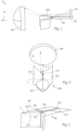
- Fig. 1 shows an exemplary lighting device 10 for a motor vehicle headlight for generating an asymmetrical low beam light distribution 50, the low beam light distribution 50 having a homogeneous light distribution in the area 51 below the intersection HV of the horizontal line HH and the vertical line VV of a measuring screen for measuring a light distribution up to at least -3 ° along the vertical line VV.
- the lighting device 10 includes a lamp 100 for emitting light, in the example shown the lamp 100 is designed as a plurality of light-emitting diodes.
- the light source can also be designed differently.
- the lighting means 100 can have a plurality of light-emitting diodes arranged next to and/or one above the other in a matrix-like manner.
- the light-emitting diodes can preferably be controlled individually, so that they can be individually switched on and off and/or dimmed.
- the LEDs are preferably controlled automatically (eg controlled by a control device).
- the lighting device 10 includes a diaphragm 200 with a diaphragm edge 200a, wherein the diaphragm 200 is arranged such that the diaphragm edge 200a contributes to generating an asymmetrical low beam light distribution 50 .
- the aperture 200 comprises a first and a second aperture section 210, 220, which, among other things, in Fig. 2 you can see.
- the second aperture section 220 is arranged elevated relative to the first aperture section 210 - seen in a correctly installed state of the lighting device in a motor vehicle - with the first and second aperture sections 210, 220 being connected to one another by a connecting section 230 of the aperture 200 .
- the lighting device 10 includes a projection optics system 300, which is set up to image the low beam light distribution 50 generated by the aperture 200 in combination with the lamp in the direction of a main radiation direction X in front of the lighting device 10 .
- the projection optics system 300 is designed as a projection lens in the example shown.
- the projection lens or the projection optics system 300 projects an image of a low beam light distribution generated inside the lighting device 10 in the area of a focal region (eg a focal plane) of the projection optics system 300 in front of the lighting device 10.
- the aperture 200 is designed to be rigid, with the aperture edge 200a being arranged in the focal region of the projection optics system 300 (a focal plane or a focal point or a focal point cloud or Petzval surface).
- Fig. 3 shows the aperture 200 in a perspective view, whereby it can be seen that the connecting section 230 of the aperture has a deflection surface 240 with an end edge 241 , which end edge 241 forms a section of the aperture edge 200a of the aperture 200 .
- the aperture edge 200a of the aperture 200 has an asymmetrical edge, which contributes to generating the asymmetrical increase in the low beam light distribution 50 , the end edge 241 of the deflection surface 240 forming this asymmetrical edge of the aperture edge 200a .
- the first and second aperture sections 210, 220 each extend - seen in a correctly installed state of the lighting device in a motor vehicle - essentially in a horizontal plane, with the first and second aperture sections 210, 220 having an offset along a second virtual axis z , wherein the second virtual axis z is arranged orthogonally to the first virtual axis y and the main radiation direction X.
- the deflection surface 240 comprises a side edge 242, which delimits the second aperture section 220 in sections and intersects the end edge 241 , the side edge 242 forming a third angle W3 with the optical axis A of the projection optical system 300 of 15° to 20°.
- the aperture 200 is located in the optical axis A , with the projection optics system 300 being arranged such that the optical axis A intersects the intersection point HV of the measuring screen.
- the left section or the first aperture section 210 viewed in the main radiation direction X is, as already described, arranged slightly below a right section or the second aperture section 220 .
- the connecting section 230 connects the two sections with one another, so that a step or an oblique transition results between the sections.
- the longitudinal extent of the connecting section 230 along the main radiation direction is one third of the focal length of the projection optical system 300.
- the front edge of the left section or the edge of the first aperture section 210 when a low beam light distribution is generated after imaging by the projection optics system 300 , an increased section of the asymmetrical light-dark boundary is generated on the own traffic side in right-hand traffic. Accordingly, the front edge or edge of the second panel section 220 results in a lowered section of the asymmetrical light-dark boundary on the side of oncoming traffic.
- a first virtual axis y is arranged orthogonally to the main radiation direction Fig. 2 or Fig. 4 .
- the deflection surface 240 extends along a flat plane, the plane having an area vector A , as in Fig. 4 can be recognized.
- the area vector A viewed in the main radiation direction X , includes a first angle W1 of 1° to 3°, preferably 2°, to the first axis y , which Fig. 5 is shown.
- the surface vector A viewed along the first axis y , includes a second angle W2 of 1° to 3°, preferably of 2° , to the main radiation direction Direction of the area 51 below the intersection HV to at least -3 ° along the vertical line VV.
- the main radiation direction X points to the left, ie starting from a right- handed Cartesian coordinate system (where the main radiation direction
- Fig. 7 shows a low beam light distribution 50 generated by a lighting device from the prior art, where it can be seen that the area 51 below the intersection HV is inhomogeneous.
- the area 51 can extend from at least -3° to at least +3° in the low beam light distribution 50 below the intersection point HV along the horizontal line HH.
- Fig. 8 shows a low beam light distribution 50 generated by a lighting device 10 according to the invention, where it can be seen that the area 51 below the intersection HV in comparison to Fig. 7 is homogeneous.
- LIST OF REFERENCE SYMBOLS lighting device 10 Low beam light distribution 50 Area 51 Light bulbs 100 cover 200 Bezel edge 200a First aperture section 210 Second aperture section 220 connection section 230 deflection surface 240 end edge 241 side edge 242
- Projection optics system 300 Main radiation direction X Virtual axis y Area vector A First angle W1 Second angle W2 Third angle W3
Landscapes
- Engineering & Computer Science (AREA)
- General Engineering & Computer Science (AREA)
- Physics & Mathematics (AREA)
- Optics & Photonics (AREA)
- Microelectronics & Electronic Packaging (AREA)
- Mechanical Engineering (AREA)
- General Physics & Mathematics (AREA)
- Non-Portable Lighting Devices Or Systems Thereof (AREA)
Abstract
Description
- Die Erfindung betrifft eine Beleuchtungsvorrichtung für einen Kraftfahrzeugscheinwerfer zur Erzeugung einer asymmetrischen Abblendlicht-Lichtverteilung, wobei die Abblendlicht-Lichtverteilung eine homogene Lichtverteilung im Bereich unterhalb des Schnittpunkts HV der Horizontallinie H-H und der Vertikallinie V-V eines Messschirms zur Messung einer Lichtverteilung bis zumindest -3° entlang der Vertikallinie V-V aufweist, wobei die Beleuchtungsvorrichtung Folgendes umfasst:
- ein Leuchtmittel zur Abstrahlung von Licht,
- eine Blende mit einer Blendenkante, wobei die Blende derart angeordnet ist, dass die Blendenkante zur Erzeugung einer asymmetrischen Abblendlicht-Lichtverteilung mitwirkt, und wobei die Blende einen ersten und einen zweiten Blendenabschnitt umfasst, wobei der zweite Blendenabschnitt zum ersten Blendenabschnitt - gesehen in einem korrekt eingebauten Zustand der Beleuchtungsvorrichtung in einem Kraftfahrzeug - erhöht angeordnet ist, und wobei der erste und der zweite Blendenabschnitt durch einen Verbindungsabschnitt der Blende miteinander verbunden sind,
- ein Projektionsoptiksystem, umfassend eine optische Achse, welches Projektionsoptiksystem eingerichtet ist, die durch die Blende in Kombination mit dem Leuchtmittel erzeugte Abblendlicht-Lichtverteilung in Richtung einer Hauptabstrahlrichtung vor die Beleuchtungsvorrichtung abzubilden.
- Weiters betrifft die Erfindung einen Kraftfahrzeugscheinwerfer umfassend zumindest eine erfindungsgemäße Beleuchtungsvorrichtung.
- Üblicherweise sind Blenden mit einer Blendenkante zur Erzeugung einer Abblendlicht-Lichtverteilung in Beleuchtungsvorrichtungen derart ausgebildet, dass die Oberseite Licht, welches vom Leuchtmittel abgestrahlt wird, reflektiert und ablenkt.
- Insbesondere der Verbindungsabschnitt der Blende sorgt dafür, dass Licht derart abgelenkt wird, dass dieses nicht mehr auf das Projektionsoptiksystem gelenkt wird und daher zur Erzeugung bzw. Formung der Abblendlicht-Lichtverteilung fehlt.
- Gerade im Bereich unterhalb der Hell-Dunkel-Grenze in der Umgebung des Schnittpunkts HV, also unterhalb des asymmetrischen Anstiegs bzw. am Beginn des Anstiegs der Abblendlicht-Lichtverteilung, kommt es daher zu Inhomogenitäten, welches zu einem Schattenbereich unterhalb des Schnittpunkts HV führt.
- Der Begriff "homogen" bedeutet in diesem Zusammenhang das Fehlen von sprunghaften Änderungen zwischen hellen und dunklen Bereichen in der Lichtverteilung.
- Es ist eine Aufgabe der Erfindung eine verbesserte Beleuchtungsvorrichtung bereitzustellen.
- Diese Aufgabe wird dadurch gelöst, dass der Verbindungsabschnitt der Blende eine Ablenkfläche mit einer Endkante aufweist, welche Endkante einen Abschnitt der Blendenkante der Blende bildet,
- wobei zur Hauptabstrahlrichtung eine erste virtuelle Achse orthogonal angeordnet ist, wobei die erste virtuelle Achse - gesehen in einem korrekt eingebauten Zustand der Beleuchtungsvorrichtung - in einer Horizontalebene angeordnet ist,
- wobei die Ablenkfläche sich entlang einer Ebene erstreckt, wobei die Ebene einen Flächenvektor aufweist, welcher Flächenvektor gesehen in Hauptabstrahlrichtung einen ersten Winkel von 1° bis 3°, vorzugsweise von 2°, zur ersten Achse einschließt, und gesehen entlang der ersten Achse einen zweiten Winkel von 1° bis 3°, vorzugsweise von 2°, zur Hauptabstrahlrichtung einschließt, um zumindest einen Teil des Lichts des Leuchtmittels, welches auf die Ablenkfläche einfällt, in Richtung des Bereichs unterhalb des Schnittpunkts HV bis zumindest -3° entlang der Vertikallinie V-V zu lenken.
- Es kann vorgesehen sein, dass die Längserstreckung des Verbindungsabschnitts entlang der Hauptabstrahlrichtung ein Drittel, vorzugsweise ein Viertel, der Brennweite des Projektionsoptiksystems ist.
- Sämtliche Angaben zu Wertebereichen in gegenständlicher Beschreibung sind so zu verstehen, dass diese beliebige und alle Teilbereiche daraus mitumfassen, z.B. ist die Angabe 1 bis 10 so zu verstehen, dass sämtliche Teilbereiche, ausgehend von der unteren Grenze 1 und der oberen Grenze 10 mit umfasst sind, d.h. sämtliche Teilbereiche beginnen mit einer unteren Grenze von 1 oder größer und enden bei einer oberen Grenze von 10 oder weniger, z.B. 1 bis 1,7, oder 3,2 bis 8,1, oder 5,5 bis 10.
- Unter "Hauptabstrahlrichtung" ist die Richtung zu verstehen, in der das Leuchtmittel infolge seiner Richtwirkung am stärksten bzw. am meisten Licht abstrahlt.
- Vorteilhafterweise fällt die Hauptabstrahlrichtung mit der optischen Achse des Projektionsoptiksystems zusammen.
- Es kann vorgesehen sein, dass die Blendenkante eine Asymmetriekante aufweist, welche zur Erzeugung des asymmetrischen Anstiegs in der Abblendlicht-Lichtverteilung mitwirkt, wobei die Endkante der Ablenkfläche die Asymmetriekante der Blendenkante bildet.
- Es kann vorgesehen sein, dass sich der erste und der zweite Blendenabschnitt jeweils - gesehen in einem korrekt eingebauten Zustand der Beleuchtungsvorrichtung in einem Kraftfahrzeug - im Wesentlichen in einer Horizontalebene erstrecken, wobei der erste und der zweite Blendenabschnitt einen Versatz entlang einer zweiten virtuellen Achse aufweisen, wobei die zweite virtuelle Achse orthogonal zur ersten virtuellen Achse und der Hauptabstrahlrichtung angeordnet ist.
- Es kann vorgesehen sein, dass das Leuchtmittel aus mehreren Leuchtdioden ausgebildet ist.
- Es kann vorgesehen sein, dass das Leuchtmittel eine oder mehrere Vorsatzoptiken, vorzugsweise Kollimatoren zur Parallelisierung von Lichtstrahlen, umfasst.
- Es kann vorgesehen sein, dass sich der Bereich der homogenen Lichtverteilung in der Abblendlicht-Lichtverteilung unterhalb des Schnittpunkts HV sich entlang der Horizontallinie H-H von zumindest -4° bis zumindest +4° erstreckt.
- Die Aufgabe wird ebenso gelöst durch einen Kraftfahrzeugscheinwerfer umfassend zumindest eine erfindungsgemäße Beleuchtungsvorrichtung.
- Nachfolgend wird die Erfindung anhand von beispielhaften Zeichnungen näher erläutert. Hierbei zeigt
- Fig. 1
- eine Seitenansicht einer beispielhaften Beleuchtungsvorrichtung, umfassend ein Leuchtmittel, eine Blende und ein Projektionsoptiksystem, wobei das Leuchtmittel in Kombination mit der Blende eine Abblendlicht-Lichtverteilung erzeugt, welche von dem Projektionsoptiksystem in Richtung einer Hauptabstrahlrichtung vor die Beleuchtungsvorrichtung abgebildet wird,
- Fig. 2
- die Beleuchtungsvorrichtung aus
Fig. 1 in einer perspektivischen, rückwärtigen (Leuchtmittel-seitigen entlang Richtung der Hauptabstrahlrichtung) Ansicht von oben; - Fig. 3
- eine perspektivische Ansicht der Blende aus dem Beispiel aus
Fig. 1 , wobei die Blende eine Blendenkante aufweist, welche zur Erzeugung der Abblendlicht-Lichtverteilung mitwirkt, wobei die Blende einen ersten und einen zweiten Blendenabschnitt aufweist, welche durch einen Verbindungsabschnitt miteinander verbunden sind, und wobei der Verbindungsabschnitt eine Ablenkfläche aufweist, welche eingerichtet ist, zumindest einen Teil des Lichts des Leuchtmittels, welches auf die Ablenkfläche eintrifft, auf das Projektionsoptiksystem umzulenken, - Fig. 4
- eine perspektivische Ansicht der Blende aus
Fig. 3 von hinten, wobei die Ablenkfläche sich entlang einer Ebene erstreckt, welche einen Flächenvektor aufweist, welcher zur Hauptabstrahlrichtung und zu einer ersten virtuellen Achse, welche orthogonal zur Hauptabstrahlrichtung und in einer Horizontalebene gelegen ist, jeweils einen Winkel einschließt, - Fig. 5
- den von dem Flächenvektor und der ersten virtuellen Achse eingeschlossenen ersten Winkel gesehen in Hauptabstrahlrichtung,
- Fig. 6
- den von dem Flächenvektor und der Hauptabstrahlrichtung eingeschlossenen zweiten Winkel gesehen entlang der ersten virtuellen Achse, wobei die Hauptabstrahlrichtung nach links zeigt, d.h. ausgehend von einem rechtshändigen kartesischen Koordinatensystem (wobei die Hauptabstrahlrichtung der x-Achse entspricht) gesehen entgegen der y-Achse bzw. entgegen der positiven Richtung der y-Achse,
- Fig. 7
- eine Abblendlicht-Lichtverteilung erzeugt durch eine Beleuchtungsvorrichtung aus dem Stand der Technik, wobei der Bereich unterhalb des Schnittpunktes HV inhomogen ist, und
- Fig. 8
- eine Abblendlicht-Lichtverteilung erzeugt durch eine erfindungsgemäße Beleuchtungsvorrichtung, wobei der Bereich unterhalb des Schnittpunktes HV homogen ist.
- Einführend sei festgehalten, dass in den unterschiedlich beschriebenen Ausführungsformen gleiche Teile mit gleichen Bezugszeichen bzw. gleichen Bauteilbezeichnungen versehen werden, wobei die in der gesamten Beschreibung enthaltenen Offenbarungen sinngemäß auf gleiche Teile mit gleichen Bezugszeichen bzw. gleichen Bauteilbezeichnungen übertragen werden können. Auch sind die in der Beschreibung gewählten Lageangaben, wie z.B. oben, unten, seitlich usw. auf die unmittelbar beschriebene sowie dargestellte Figur bezogen und sind diese Lageangaben bei einer Lageänderung sinngemäß auf die neue Lage zu übertragen.
-
Fig. 1 zeigt eine beispielhafte Beleuchtungsvorrichtung 10 für einen Kraftfahrzeugscheinwerfer zur Erzeugung einer asymmetrischen Abblendlicht-Lichtverteilung 50, wobei die Abblendlicht-Lichtverteilung 50 eine homogene Lichtverteilung im Bereich 51 unterhalb des Schnittpunkts HV der Horizontallinie H-H und der Vertikallinie V-V eines Messschirms zur Messung einer Lichtverteilung bis zumindest -3° entlang der Vertikallinie V-V aufweist. - Die Beleuchtungsvorrichtung 10 umfasst ein Leuchtmittel 100 zur Abstrahlung von Licht, wobei im gezeigten Beispiel das Leuchtmittel 100 als mehrerer Leuchtdioden ausgebildet ist. Selbstverständlich kann das Leuchtmittel auch anderweitig ausgebildet sein. Insbesondere kann das Leuchtmittel 100 eine Vielzahl matrixartig neben- und/oder übereinander angeordneter Leuchtdioden aufweisen. Die Leuchtdioden sind vorzugsweise einzeln ansteuerbar, sodass sie individuell ein- und ausgeschaltet und/oder gedimmt werden können. Die Ansteuerung der Leuchtdioden erfolgt vorzugsweise automatisch (z.B. durch ein Steuergerät gesteuert).
- Weiters umfasst die Beleuchtungsvorrichtung 10 eine Blende 200 mit einer Blendenkante 200a, wobei die Blende 200 derart angeordnet ist, dass die Blendenkante 200a zur Erzeugung einer asymmetrischen Abblendlicht-Lichtverteilung 50 mitwirkt.
- Die Blende 200 umfasst einen ersten und einen zweiten Blendenabschnitt 210, 220, welche in unter anderem in
Fig. 2 zu sehen sind. Der zweite Blendenabschnitt 220 ist zum ersten Blendenabschnitt 210 - gesehen in einem korrekt eingebauten Zustand der Beleuchtungsvorrichtung in einem Kraftfahrzeug - erhöht angeordnet, wobei der erste und der zweite Blendenabschnitt 210, 220 durch einen Verbindungsabschnitt 230 der Blende 200 miteinander verbunden sind. - Ferner umfasst die Beleuchtungsvorrichtung 10 ein Projektionsoptiksystem 300, welches eingerichtet ist, die durch die Blende 200 in Kombination mit dem Leuchtmittel erzeugte Abblendlicht-Lichtverteilung 50 in Richtung einer Hauptabstrahlrichtung X vor die Beleuchtungsvorrichtung 10 abzubilden. Das Projektionsoptiksystem 300 ist im gezeigten Beispiel als eine Projektionslinse ausgebildet. Die Projektionslinse bzw. das Projektionsoptiksystem 300 projiziert ein Bild einer im Inneren der Beleuchtungsvorrichtung 10 im Bereich eines Fokalbereichs (z.B. einer Brennebene) des Projektionsoptiksystems 300 erzeugten Abblendlicht-Lichtverteilung vor die Beleuchtungsvorrichtung 10.
- Die Blende 200 ist starr ausgebildet, wobei die Blendenkante 200a im Fokalbereich des Projektionsoptiksystems 300 (einer Brennebene bzw. einem Brennpunkt oder eine Brennpunktwolke bzw. Petzval-Fläche) angeordnet ist.
-
Fig. 3 zeigt die Blende 200 in einer perspektivischen Ansicht, wobei zu erkennen ist, dass der Verbindungsabschnitt 230 der Blende eine Ablenkfläche 240 mit einer Endkante 241 aufweist, welche Endkante 241 einen Abschnitt der Blendenkante 200a der Blende 200 bildet. - Wie in den Figuren, insbesondere in
Fig. 3 zu sehen ist, weist die Blendenkante 200a der Blende 200 eine Asymmetriekante aufweist, welche zur Erzeugung des asymmetrischen Anstiegs in der Abblendlicht-Lichtverteilung 50 mitwirkt, wobei die Endkante 241 der Ablenkfläche 240 diese Asymmetriekante der Blendenkante 200a bildet. - Der erste und der zweite Blendenabschnitt 210, 220 erstrecken sich jeweils - gesehen in einem korrekt eingebauten Zustand der Beleuchtungsvorrichtung in einem Kraftfahrzeug - im Wesentlichen in einer Horizontalebene, wobei der erste und der zweite Blendenabschnitt 210, 220 einen Versatz entlang einer zweiten virtuellen Achse z aufweisen, wobei die zweite virtuelle Achse z orthogonal zur ersten virtuellen Achse y und der Hauptabstrahlrichtung X angeordnet ist. Ferner umfasst die Ablenkfläche 240 eine Seitenkante 242, welche den zweiten Blendenabschnitt 220 abschnittsweise begrenzt und die Endkante 241 schneidet, wobei die Seitenkante 242 einen dritten Winkel W3 mit der optischen Achse A des Projektionsoptiksystems 300 von 15° bis 20° einschließt. Die Blende 200 ist dabei in der optischen Achse A gelegen, wobei das Projektionsoptiksystem 300 derart angeordnet ist, dass die optische Achse A den Schnittpunkt HV des Messschirms schneidet.
- Der in Hauptabstrahlrichtung X betrachtete linker Abschnitt bzw. der erste Blendenabschnitt 210 ist, wie bereits geschildert, geringfügig unterhalb eines rechten Abschnitts bzw. des zweiten Blendenabschnitts 220 angeordnet. Der Verbindungsabschnitt 230 verbindet die beiden Abschnitte miteinander, sodass sich gewissermaßen eine Stufe bzw. ein schräger Übergang zwischen den Abschnitten ergibt.
- Die Längserstreckung des Verbindungsabschnitts 230 entlang der Hauptabstrahlrichtung ist in den gezeigten Figuren ein Drittel der Brennweite des Projektionsoptiksystems 300.
- Durch den vorderen Rand des linken Abschnitt bzw. der Kante des ersten Blendenabschnitts 210 wird bei Erzeugung einer Abblendlicht-Lichtverteilung nach der Abbildung durch das Projektionsoptiksystem 300 ein erhöhter Abschnitt der asymmetrischen Helldunkelgrenze auf der eigenen Verkehrsseite bei Rechtsverkehr erzeugt. Dementsprechend ergibt sich durch den vorderen Rand bzw. der Kante des zweiten Blendenabschnitts 220 ein abgesenkter Abschnitt der asymmetrischen Helldunkelgrenze auf der Gegenverkehrsseite.
- Zur Hauptabstrahlrichtung X ist eine erste virtuelle Achse y orthogonal angeordnet, wobei die erste virtuelle Achse y - gesehen in einem korrekt eingebauten Zustand der Beleuchtungsvorrichtung in einem Kraftfahrzeug - in einer Horizontalebene angeordnet ist, beispielsweise zu sehen in
Fig. 2 oderFig. 4 . - Die Ablenkfläche 240 erstreckt sich entlang einer flachen Ebene, wobei die Ebene einen Flächenvektor A aufweist, wie in
Fig. 4 zu erkennen ist. Der Flächenvektor A schließt gesehen in Hauptabstrahlrichtung X einen ersten Winkel W1 von 1° bis 3°, vorzugsweise von 2°, zur ersten Achse y ein, was inFig. 5 dargestellt ist. - Ferner schließt der Flächenvektor A gesehen entlang der ersten Achse y einen zweiten Winkel W2 von 1° bis 3°, vorzugsweise von 2°, zur Hauptabstrahlrichtung X ein, um zumindest einen Teil des Lichts des Leuchtmittels 100, welches auf die Ablenkfläche 240 einfällt, in Richtung des Bereichs 51 unterhalb des Schnittpunkts HV bis zumindest -3° entlang der Vertikallinie V-V zu lenken. Wie in
Fig. 6 zu sehen ist, zeigt die Hauptabstrahlrichtung X nach links, d.h. ausgehend von einem rechtshändigen kartesischen Koordinatensystem (wobei die Hauptabstrahlrichtung X der x-Achse entspricht) wird entgegen der y-Achse bzw. entgegen der positiven Richtung der y-Achse gesehen. -
Fig. 7 zeigt eine Abblendlicht-Lichtverteilung 50 erzeugt durch eine Beleuchtungsvorrichtung aus dem Stand der Technik, wobei zu sehen ist, dass der Bereich 51 unterhalb des Schnittpunkts HV inhomogen ist. Der Bereich 51 kann sich in der Abblendlicht-Lichtverteilung 50 unterhalb des Schnittpunkts HV entlang der Horizontallinie H-H von zumindest -3° bis zumindest +3° erstrecken. -
Fig. 8 zeigt eine Abblendlicht-Lichtverteilung 50 erzeugt durch eine erfindungsgemäße Beleuchtungsvorrichtung 10, wobei zu sehen ist, dass der Bereich 51 unterhalb des Schnittpunkts HV im Vergleich zuFig. 7 homogen ist.LISTE DER BEZUGSZEICHEN Beleuchtungsvorrichtung 10 Abblendlicht-Lichtverteilung 50 Bereich 51 Leuchtmittel 100 Blende 200 Blendenkante 200a Erster Blendenabschnitt 210 Zweiter Blendenabschnitt 220 Verbindungsabschnitt 230 Ablenkfläche 240 Endkante 241 Seitenkante 242 Projektionsoptiksystem 300 Hauptabstrahlrichtung X Virtuelle Achse y Flächenvektor A Erster Winkel W1 Zweiter Winkel W2 Dritter Winkel W3
Claims (9)
- Beleuchtungsvorrichtung (10) für einen Kraftfahrzeugscheinwerfer zur Erzeugung einer asymmetrischen Abblendlicht-Lichtverteilung (50), wobei die Abblendlicht-Lichtverteilung (50) eine homogene Lichtverteilung im Bereich (51) unterhalb des Schnittpunkts HV der Horizontallinie H-H und der Vertikallinie V-V eines Messschirms zur Messung einer Lichtverteilung bis zumindest -3° entlang der Vertikallinie V-V aufweist, wobei die Beleuchtungsvorrichtung (10) Folgendes umfasst:- ein Leuchtmittel (100) zur Abstrahlung von Licht,- eine Blende (200) mit einer Blendenkante (200a), wobei die Blende (200) derart angeordnet ist, dass die Blendenkante (200a) zur Erzeugung einer asymmetrischen Abblendlicht-Lichtverteilung (50) mitwirkt, und wobei die Blende (200) einen ersten und einen zweiten Blendenabschnitt (210, 220) umfasst, wobei der zweite Blendenabschnitt (220) zum ersten Blendenabschnitt (210) - gesehen in einem korrekt eingebauten Zustand der Beleuchtungsvorrichtung in einem Kraftfahrzeug - erhöht angeordnet ist, und wobei der erste und der zweite Blendenabschnitt (210, 220) durch einen Verbindungsabschnitt (230) der Blende (200) miteinander verbunden sind,- ein Projektionsoptiksystem (300) umfassende eine optische Achse (A), welches Projektionsoptiksystem (300) eingerichtet ist, die durch die Blende (200) in Kombination mit dem Leuchtmittel erzeugte Abblendlicht-Lichtverteilung (50) in Richtung einer Hauptabstrahlrichtung (X) vor die Beleuchtungsvorrichtung (10) abzubilden,dadurch gekennzeichnet, dassder Verbindungsabschnitt (230) der Blende eine Ablenkfläche (240) mit einer Endkante (241) aufweist, welche Endkante (241) einen Abschnitt der Blendenkante (200a) der Blende (200) bildet,wobei zur Hauptabstrahlrichtung (X) eine erste virtuelle Achse (y) orthogonal angeordnet ist, wobei die erste virtuelle Achse (y) - gesehen in einem korrekt eingebauten Zustand der Beleuchtungsvorrichtung - in einer Horizontalebene angeordnet ist,wobei die Ablenkfläche (240) sich entlang einer Ebene erstreckt, wobei die Ebene einen Flächenvektor (A) aufweist, welcher Flächenvektor (A) gesehen in Hauptabstrahlrichtung (X) einen ersten Winkel (W1) von 1° bis 3°, vorzugsweise von 2°, zur ersten Achse (y) einschließt, und gesehen entlang der ersten Achse (y) einen zweiten Winkel (W2) von 1° bis 3°, vorzugsweise von 2°, zur Hauptabstrahlrichtung (X) einschließt, um zumindest einen Teil des Lichts des Leuchtmittels (100), welches auf die Ablenkfläche (240) einfällt, in Richtung des Bereichs (51) unterhalb des Schnittpunkts HV bis zumindest -3° entlang der Vertikallinie V-V zu lenken.
- Beleuchtungsvorrichtung nach Anspruch 1, dadurch gekennzeichnet, dass die Blendenkante (200a) eine Asymmetriekante aufweist, welche zur Erzeugung des asymmetrischen Anstiegs in der Abblendlicht-Lichtverteilung (50) mitwirkt, wobei die Endkante (241) der Ablenkfläche (240) die Asymmetriekante der Blendenkante (200a) bildet.
- Beleuchtungsvorrichtung nach Anspruch 1 oder 2, dadurch gekennzeichnet, dass sich der erste und der zweite Blendenabschnitt (210, 220) jeweils - gesehen in einem korrekt eingebauten Zustand der Beleuchtungsvorrichtung in einem Kraftfahrzeug - im Wesentlichen in einer Horizontalebene erstrecken, wobei der erste und der zweite Blendenabschnitt (210, 220) einen Versatz entlang einer zweiten virtuellen Achse (z) aufweisen, wobei die zweite virtuelle Achse (z) orthogonal zur ersten virtuellen Achse (y) und der Hauptabstrahlrichtung (X) angeordnet ist.
- Beleuchtungsvorrichtung nach einem der Ansprüche 1 bis 4, dadurch gekennzeichnet, dass die Ablenkfläche eine Seitenkante (242) aufweist, welche den zweiten Blendenabschnitt (220) abschnittsweise begrenzt und die Endkante (241) schneidet, wobei die Seitenkante (242) einen dritten Winkel (W3) mit der optischen Achse (A) des Projektionsoptiksystems (300) von 15° bis 20° einschließt.
- Beleuchtungsvorrichtung nach einem der Ansprüche 1 bis 4, dadurch gekennzeichnet, dass die Längserstreckung des Verbindungsabschnitts (230) entlang der Hauptabstrahlrichtung (X) zumindest ein Drittel, vorzugsweise zumindest ein Viertel, der Brennweite des Projektionsoptiksystems (300) beträgt.
- Beleuchtungsvorrichtung nach einem der Ansprüche 1 bis 5, dadurch gekennzeichnet, dass das Leuchtmittel (100) aus mehreren Leuchtdioden ausgebildet ist.
- Beleuchtungsvorrichtung nach einem der Ansprüche 1 bis 6, dadurch gekennzeichnet, dass das Leuchtmittel (100) eine oder mehrere Vorsatzoptiken, vorzugsweise Kollimatoren zur Parallelisierung von Lichtstrahlen, umfasst.
- Beleuchtungsvorrichtung nach einem der Ansprüche 1 bis 4, dadurch gekennzeichnet, dass sich der Bereich (51) der homogenen Lichtverteilung in der Abblendlicht-Lichtverteilung (50) unterhalb des Schnittpunkts HV sich entlang der Horizontallinie H-H von zumindest -4° bis zumindest +4° erstreckt.
- Kraftfahrzeugscheinwerfer umfassend zumindest eine Beleuchtungsvorrichtung (10) nach einem der Ansprüche 1 bis 8.
Priority Applications (5)
| Application Number | Priority Date | Filing Date | Title |
|---|---|---|---|
| EP22190799.1A EP4325113B1 (de) | 2022-08-17 | 2022-08-17 | Beleuchtungsvorrichtung für einen kraftfahrzeugscheinwerfer |
| KR1020230083462A KR102864471B1 (ko) | 2022-08-17 | 2023-06-28 | 자동차 헤드라이트용 조명 장치 |
| JP2023113687A JP7540049B2 (ja) | 2022-08-17 | 2023-07-11 | 自動車投光器用照明装置 |
| CN202311030286.3A CN117588699A (zh) | 2022-08-17 | 2023-08-16 | 用于机动车前照灯的照明设备 |
| US18/234,564 US11965633B2 (en) | 2022-08-17 | 2023-08-16 | Illumination device for motor vehicle headlight |
Applications Claiming Priority (1)
| Application Number | Priority Date | Filing Date | Title |
|---|---|---|---|
| EP22190799.1A EP4325113B1 (de) | 2022-08-17 | 2022-08-17 | Beleuchtungsvorrichtung für einen kraftfahrzeugscheinwerfer |
Publications (2)
| Publication Number | Publication Date |
|---|---|
| EP4325113A1 true EP4325113A1 (de) | 2024-02-21 |
| EP4325113B1 EP4325113B1 (de) | 2025-02-26 |
Family
ID=82943014
Family Applications (1)
| Application Number | Title | Priority Date | Filing Date |
|---|---|---|---|
| EP22190799.1A Active EP4325113B1 (de) | 2022-08-17 | 2022-08-17 | Beleuchtungsvorrichtung für einen kraftfahrzeugscheinwerfer |
Country Status (5)
| Country | Link |
|---|---|
| US (1) | US11965633B2 (de) |
| EP (1) | EP4325113B1 (de) |
| JP (1) | JP7540049B2 (de) |
| KR (1) | KR102864471B1 (de) |
| CN (1) | CN117588699A (de) |
Citations (7)
| Publication number | Priority date | Publication date | Assignee | Title |
|---|---|---|---|---|
| US20080239741A1 (en) * | 2007-03-26 | 2008-10-02 | Koito Manufacturing Co., Ltd. | Lamp unit of vehicle headlamp |
| DE102008015246A1 (de) * | 2007-03-26 | 2008-11-27 | Koito Manufacturing Co., Ltd. | Leuchteneinheit eines Fahrzeugscheinwerfers |
| US20100309678A1 (en) * | 2009-06-04 | 2010-12-09 | Shinji Yamagata | Vehicular lighting fixture |
| US20130051054A1 (en) * | 2011-08-30 | 2013-02-28 | Shinji Yamagata | Vehicle headlamp |
| EP3211292A1 (de) * | 2016-02-22 | 2017-08-30 | Excellence Optoelectronics (Dong Guan) Ltd. | Kfz-scheinwerfermodul |
| CN207350141U (zh) * | 2017-06-22 | 2018-05-11 | 上海小糸车灯有限公司 | 一种用于汽车前照灯近光模组的遮光板及汽车前照灯 |
| EP3361146A1 (de) * | 2017-02-09 | 2018-08-15 | Excellence Optoelectronics Inc. | Schattierungsmodul zur erhöhung der lichtintensität eines fahrzeugscheinwerfers |
Family Cites Families (9)
| Publication number | Priority date | Publication date | Assignee | Title |
|---|---|---|---|---|
| US7670038B2 (en) * | 2004-09-20 | 2010-03-02 | Koninklijke Philips Electronics N.V. | LED collimator element with an asymmetrical collimator |
| JP5423159B2 (ja) * | 2009-06-04 | 2014-02-19 | スタンレー電気株式会社 | 車両用灯具 |
| JP5620714B2 (ja) | 2010-05-17 | 2014-11-05 | 株式会社小糸製作所 | ロービーム用灯具ユニット |
| GB2509764B (en) * | 2013-01-14 | 2018-09-12 | Kaleido Tech Aps | A lens array and a method of making a lens array |
| KR102289755B1 (ko) * | 2014-12-24 | 2021-08-13 | 에스엘 주식회사 | 헤드 램프용 로우빔 쉴드 |
| JP6931664B2 (ja) * | 2016-05-12 | 2021-09-08 | ルミレッズ ホールディング ベーフェー | 光ガイドを用いた照明装置 |
| US10823361B2 (en) | 2017-01-25 | 2020-11-03 | Maxell, Ltd. | Headlight apparatus |
| EP3653926B1 (de) * | 2018-11-19 | 2022-02-16 | ZKW Group GmbH | Beleuchtungsvorrichtung für einen kraftfahrzeugscheinwerfer sowie kraftfahrzeugscheinwerfer |
| US11971147B2 (en) | 2019-11-01 | 2024-04-30 | Ichikoh Industries, Ltd. | Vehicle light guide and vehicle headlight |
-
2022
- 2022-08-17 EP EP22190799.1A patent/EP4325113B1/de active Active
-
2023
- 2023-06-28 KR KR1020230083462A patent/KR102864471B1/ko active Active
- 2023-07-11 JP JP2023113687A patent/JP7540049B2/ja active Active
- 2023-08-16 US US18/234,564 patent/US11965633B2/en active Active
- 2023-08-16 CN CN202311030286.3A patent/CN117588699A/zh active Pending
Patent Citations (7)
| Publication number | Priority date | Publication date | Assignee | Title |
|---|---|---|---|---|
| US20080239741A1 (en) * | 2007-03-26 | 2008-10-02 | Koito Manufacturing Co., Ltd. | Lamp unit of vehicle headlamp |
| DE102008015246A1 (de) * | 2007-03-26 | 2008-11-27 | Koito Manufacturing Co., Ltd. | Leuchteneinheit eines Fahrzeugscheinwerfers |
| US20100309678A1 (en) * | 2009-06-04 | 2010-12-09 | Shinji Yamagata | Vehicular lighting fixture |
| US20130051054A1 (en) * | 2011-08-30 | 2013-02-28 | Shinji Yamagata | Vehicle headlamp |
| EP3211292A1 (de) * | 2016-02-22 | 2017-08-30 | Excellence Optoelectronics (Dong Guan) Ltd. | Kfz-scheinwerfermodul |
| EP3361146A1 (de) * | 2017-02-09 | 2018-08-15 | Excellence Optoelectronics Inc. | Schattierungsmodul zur erhöhung der lichtintensität eines fahrzeugscheinwerfers |
| CN207350141U (zh) * | 2017-06-22 | 2018-05-11 | 上海小糸车灯有限公司 | 一种用于汽车前照灯近光模组的遮光板及汽车前照灯 |
Also Published As
| Publication number | Publication date |
|---|---|
| JP2024028137A (ja) | 2024-03-01 |
| US11965633B2 (en) | 2024-04-23 |
| US20240060616A1 (en) | 2024-02-22 |
| CN117588699A (zh) | 2024-02-23 |
| KR20240024734A (ko) | 2024-02-26 |
| EP4325113B1 (de) | 2025-02-26 |
| JP7540049B2 (ja) | 2024-08-26 |
| KR102864471B1 (ko) | 2025-09-24 |
Similar Documents
| Publication | Publication Date | Title |
|---|---|---|
| DE102017219953B4 (de) | Fahrzeugleuchte | |
| EP2799761B1 (de) | Lichtmodul für einen kraftfahrzeugscheinwerfer | |
| DE102012008833B4 (de) | Beleuchtungsanordnung und Fahrzeugscheinwerfer | |
| AT518551B1 (de) | Kraftfahrzeugbeleuchtungsvorrichtung | |
| DE102011078653B4 (de) | Vorsatzoptik zur Bündelung von ausgesandtem Licht mindestens einer Halbleiterlichtquelle | |
| DE102018110793B4 (de) | Projektionsscheinwerfer | |
| EP3861242B1 (de) | Beleuchtungsvorrichtung für einen kraftfahrzeugscheinwerfer | |
| DE102011001865B4 (de) | Beleuchtungsvorrichtung | |
| WO2014012773A1 (de) | Scheinwerfer für fahrzeuge | |
| DE102020114767B4 (de) | Beleuchtungsvorrichtung und Herstellungsverfahren | |
| WO2019158319A1 (de) | Kraftfahrzeugscheinwerfer mit einer abschirmblende zur abschirmung eintretender sonnenstrahlung | |
| DE102010013821A1 (de) | Leuchtenvorrichtung und Verfahren zur Erzeugung einer ersten und einer zweiten Lichtfunktion für ein Fahrzeug | |
| WO2019197204A1 (de) | Scheinwerfer für fahrzeuge | |
| DE102018211277A1 (de) | Optische Einheit | |
| DE102012022282B4 (de) | 1 - 13Verfahren und Vorrichtung zum Kalibrieren der Hell-Dunkel-Grenze einer Gesamtlichtverteilung zumindest einer Lichtfunktion einer Scheinwerferanordnung für ein Fahrzeug | |
| DE102021206735A1 (de) | Scheinwerfermodul eines Fahrzeugscheinwerfers, Fahrzeugscheinwerfer und den Fahrzeugscheinwerfer aufweisendes Fahrzeug | |
| DE102015201856B4 (de) | Kfz-Scheinwerfer | |
| EP3896334A1 (de) | Beleuchtungsvorrichtung für einen kraftfahrzeugscheinwerfer | |
| EP4325113B1 (de) | Beleuchtungsvorrichtung für einen kraftfahrzeugscheinwerfer | |
| DE102016109863A1 (de) | Bilderzeugungseinrichtung für eine Kopf-oben-Anzeigevorrichtung eines Kraftfahrzeugs mit Ablenkeinheit, Kopf-oben-Anzeigevorrichtung sowie Kraftfahrzeug | |
| EP4202289A1 (de) | Optiksystem für einen kraftfahrzeugscheinwerfer | |
| DE112024000562T5 (de) | Fahrzeuglampenanordnung | |
| EP4316911B1 (de) | Kraftfahrzeuglichtsystem zur abstrahlung von positionsbegrenzten bodenprojektionen | |
| EP4217647B1 (de) | Beleuchtungsvorrichtung für einen kraftfahrzeugscheinwerfer | |
| DE102019129369A1 (de) | Lichtmodul, Beleuchtungseinrichtung und Kraftfahrzeug |
Legal Events
| Date | Code | Title | Description |
|---|---|---|---|
| PUAI | Public reference made under article 153(3) epc to a published international application that has entered the european phase |
Free format text: ORIGINAL CODE: 0009012 |
|
| STAA | Information on the status of an ep patent application or granted ep patent |
Free format text: STATUS: THE APPLICATION HAS BEEN PUBLISHED |
|
| AK | Designated contracting states |
Kind code of ref document: A1 Designated state(s): AL AT BE BG CH CY CZ DE DK EE ES FI FR GB GR HR HU IE IS IT LI LT LU LV MC MK MT NL NO PL PT RO RS SE SI SK SM TR |
|
| STAA | Information on the status of an ep patent application or granted ep patent |
Free format text: STATUS: REQUEST FOR EXAMINATION WAS MADE |
|
| 17P | Request for examination filed |
Effective date: 20240626 |
|
| RBV | Designated contracting states (corrected) |
Designated state(s): AL AT BE BG CH CY CZ DE DK EE ES FI FR GB GR HR HU IE IS IT LI LT LU LV MC MK MT NL NO PL PT RO RS SE SI SK SM TR |
|
| RIN1 | Information on inventor provided before grant (corrected) |
Inventor name: KOSMAS, KYRIAKOS Inventor name: MANDL, BERNHARD Inventor name: SCHAGER, ALEXANDER Inventor name: PARK, TAEYANG |
|
| GRAP | Despatch of communication of intention to grant a patent |
Free format text: ORIGINAL CODE: EPIDOSNIGR1 |
|
| STAA | Information on the status of an ep patent application or granted ep patent |
Free format text: STATUS: GRANT OF PATENT IS INTENDED |
|
| INTG | Intention to grant announced |
Effective date: 20241216 |
|
| GRAS | Grant fee paid |
Free format text: ORIGINAL CODE: EPIDOSNIGR3 |
|
| GRAA | (expected) grant |
Free format text: ORIGINAL CODE: 0009210 |
|
| STAA | Information on the status of an ep patent application or granted ep patent |
Free format text: STATUS: THE PATENT HAS BEEN GRANTED |
|
| AK | Designated contracting states |
Kind code of ref document: B1 Designated state(s): AL AT BE BG CH CY CZ DE DK EE ES FI FR GB GR HR HU IE IS IT LI LT LU LV MC MK MT NL NO PL PT RO RS SE SI SK SM TR |
|
| REG | Reference to a national code |
Ref country code: GB Ref legal event code: FG4D Free format text: NOT ENGLISH |
|
| REG | Reference to a national code |
Ref country code: CH Ref legal event code: EP |
|
| REG | Reference to a national code |
Ref country code: DE Ref legal event code: R096 Ref document number: 502022003010 Country of ref document: DE |
|
| REG | Reference to a national code |
Ref country code: IE Ref legal event code: FG4D Free format text: LANGUAGE OF EP DOCUMENT: GERMAN |
|
| P01 | Opt-out of the competence of the unified patent court (upc) registered |
Free format text: CASE NUMBER: APP_14112/2025 Effective date: 20250321 |
|
| REG | Reference to a national code |
Ref country code: NL Ref legal event code: MP Effective date: 20250226 |
|
| PG25 | Lapsed in a contracting state [announced via postgrant information from national office to epo] |
Ref country code: RS Free format text: LAPSE BECAUSE OF FAILURE TO SUBMIT A TRANSLATION OF THE DESCRIPTION OR TO PAY THE FEE WITHIN THE PRESCRIBED TIME-LIMIT Effective date: 20250526 |
|
| PG25 | Lapsed in a contracting state [announced via postgrant information from national office to epo] |
Ref country code: FI Free format text: LAPSE BECAUSE OF FAILURE TO SUBMIT A TRANSLATION OF THE DESCRIPTION OR TO PAY THE FEE WITHIN THE PRESCRIBED TIME-LIMIT Effective date: 20250226 |
|
| PG25 | Lapsed in a contracting state [announced via postgrant information from national office to epo] |
Ref country code: PL Free format text: LAPSE BECAUSE OF FAILURE TO SUBMIT A TRANSLATION OF THE DESCRIPTION OR TO PAY THE FEE WITHIN THE PRESCRIBED TIME-LIMIT Effective date: 20250226 |
|
| PG25 | Lapsed in a contracting state [announced via postgrant information from national office to epo] |
Ref country code: ES Free format text: LAPSE BECAUSE OF FAILURE TO SUBMIT A TRANSLATION OF THE DESCRIPTION OR TO PAY THE FEE WITHIN THE PRESCRIBED TIME-LIMIT Effective date: 20250226 |
|
| REG | Reference to a national code |
Ref country code: LT Ref legal event code: MG9D |
|
| PG25 | Lapsed in a contracting state [announced via postgrant information from national office to epo] |
Ref country code: NO Free format text: LAPSE BECAUSE OF FAILURE TO SUBMIT A TRANSLATION OF THE DESCRIPTION OR TO PAY THE FEE WITHIN THE PRESCRIBED TIME-LIMIT Effective date: 20250526 Ref country code: IS Free format text: LAPSE BECAUSE OF FAILURE TO SUBMIT A TRANSLATION OF THE DESCRIPTION OR TO PAY THE FEE WITHIN THE PRESCRIBED TIME-LIMIT Effective date: 20250626 |
|
| PG25 | Lapsed in a contracting state [announced via postgrant information from national office to epo] |
Ref country code: NL Free format text: LAPSE BECAUSE OF FAILURE TO SUBMIT A TRANSLATION OF THE DESCRIPTION OR TO PAY THE FEE WITHIN THE PRESCRIBED TIME-LIMIT Effective date: 20250226 |
|
| PG25 | Lapsed in a contracting state [announced via postgrant information from national office to epo] |
Ref country code: HR Free format text: LAPSE BECAUSE OF FAILURE TO SUBMIT A TRANSLATION OF THE DESCRIPTION OR TO PAY THE FEE WITHIN THE PRESCRIBED TIME-LIMIT Effective date: 20250226 |
|
| PG25 | Lapsed in a contracting state [announced via postgrant information from national office to epo] |
Ref country code: PT Free format text: LAPSE BECAUSE OF FAILURE TO SUBMIT A TRANSLATION OF THE DESCRIPTION OR TO PAY THE FEE WITHIN THE PRESCRIBED TIME-LIMIT Effective date: 20250626 Ref country code: LV Free format text: LAPSE BECAUSE OF FAILURE TO SUBMIT A TRANSLATION OF THE DESCRIPTION OR TO PAY THE FEE WITHIN THE PRESCRIBED TIME-LIMIT Effective date: 20250226 |
|
| PG25 | Lapsed in a contracting state [announced via postgrant information from national office to epo] |
Ref country code: BG Free format text: LAPSE BECAUSE OF FAILURE TO SUBMIT A TRANSLATION OF THE DESCRIPTION OR TO PAY THE FEE WITHIN THE PRESCRIBED TIME-LIMIT Effective date: 20250226 Ref country code: GR Free format text: LAPSE BECAUSE OF FAILURE TO SUBMIT A TRANSLATION OF THE DESCRIPTION OR TO PAY THE FEE WITHIN THE PRESCRIBED TIME-LIMIT Effective date: 20250527 |
|
| PG25 | Lapsed in a contracting state [announced via postgrant information from national office to epo] |
Ref country code: SE Free format text: LAPSE BECAUSE OF FAILURE TO SUBMIT A TRANSLATION OF THE DESCRIPTION OR TO PAY THE FEE WITHIN THE PRESCRIBED TIME-LIMIT Effective date: 20250226 |
|
| PG25 | Lapsed in a contracting state [announced via postgrant information from national office to epo] |
Ref country code: SM Free format text: LAPSE BECAUSE OF FAILURE TO SUBMIT A TRANSLATION OF THE DESCRIPTION OR TO PAY THE FEE WITHIN THE PRESCRIBED TIME-LIMIT Effective date: 20250226 |
|
| PG25 | Lapsed in a contracting state [announced via postgrant information from national office to epo] |
Ref country code: DK Free format text: LAPSE BECAUSE OF FAILURE TO SUBMIT A TRANSLATION OF THE DESCRIPTION OR TO PAY THE FEE WITHIN THE PRESCRIBED TIME-LIMIT Effective date: 20250226 |
|
| PGFP | Annual fee paid to national office [announced via postgrant information from national office to epo] |
Ref country code: DE Payment date: 20250819 Year of fee payment: 4 |
|
| PG25 | Lapsed in a contracting state [announced via postgrant information from national office to epo] |
Ref country code: IT Free format text: LAPSE BECAUSE OF FAILURE TO SUBMIT A TRANSLATION OF THE DESCRIPTION OR TO PAY THE FEE WITHIN THE PRESCRIBED TIME-LIMIT Effective date: 20250226 |
|
| PGFP | Annual fee paid to national office [announced via postgrant information from national office to epo] |
Ref country code: FR Payment date: 20250821 Year of fee payment: 4 Ref country code: AT Payment date: 20251020 Year of fee payment: 4 |
|
| PG25 | Lapsed in a contracting state [announced via postgrant information from national office to epo] |
Ref country code: CZ Free format text: LAPSE BECAUSE OF FAILURE TO SUBMIT A TRANSLATION OF THE DESCRIPTION OR TO PAY THE FEE WITHIN THE PRESCRIBED TIME-LIMIT Effective date: 20250226 Ref country code: EE Free format text: LAPSE BECAUSE OF FAILURE TO SUBMIT A TRANSLATION OF THE DESCRIPTION OR TO PAY THE FEE WITHIN THE PRESCRIBED TIME-LIMIT Effective date: 20250226 |
|
| PG25 | Lapsed in a contracting state [announced via postgrant information from national office to epo] |
Ref country code: RO Free format text: LAPSE BECAUSE OF FAILURE TO SUBMIT A TRANSLATION OF THE DESCRIPTION OR TO PAY THE FEE WITHIN THE PRESCRIBED TIME-LIMIT Effective date: 20250226 |
|
| PG25 | Lapsed in a contracting state [announced via postgrant information from national office to epo] |
Ref country code: SK Free format text: LAPSE BECAUSE OF FAILURE TO SUBMIT A TRANSLATION OF THE DESCRIPTION OR TO PAY THE FEE WITHIN THE PRESCRIBED TIME-LIMIT Effective date: 20250226 |
|
| REG | Reference to a national code |
Ref country code: DE Ref legal event code: R097 Ref document number: 502022003010 Country of ref document: DE |
|
| PLBE | No opposition filed within time limit |
Free format text: ORIGINAL CODE: 0009261 |
|
| STAA | Information on the status of an ep patent application or granted ep patent |
Free format text: STATUS: NO OPPOSITION FILED WITHIN TIME LIMIT |
|
| REG | Reference to a national code |
Ref country code: CH Ref legal event code: L10 Free format text: ST27 STATUS EVENT CODE: U-0-0-L10-L00 (AS PROVIDED BY THE NATIONAL OFFICE) Effective date: 20260107 |
|
| 26N | No opposition filed |
Effective date: 20251127 |
|
| REG | Reference to a national code |
Ref country code: CH Ref legal event code: H13 Free format text: ST27 STATUS EVENT CODE: U-0-0-H10-H13 (AS PROVIDED BY THE NATIONAL OFFICE) Effective date: 20260324 |
|
| PG25 | Lapsed in a contracting state [announced via postgrant information from national office to epo] |
Ref country code: MC Free format text: LAPSE BECAUSE OF FAILURE TO SUBMIT A TRANSLATION OF THE DESCRIPTION OR TO PAY THE FEE WITHIN THE PRESCRIBED TIME-LIMIT Effective date: 20250226 |
|
| PG25 | Lapsed in a contracting state [announced via postgrant information from national office to epo] |
Ref country code: LU Free format text: LAPSE BECAUSE OF NON-PAYMENT OF DUE FEES Effective date: 20250817 |
|
| PG25 | Lapsed in a contracting state [announced via postgrant information from national office to epo] |
Ref country code: CH Free format text: LAPSE BECAUSE OF NON-PAYMENT OF DUE FEES Effective date: 20250831 |
|
| REG | Reference to a national code |
Ref country code: BE Ref legal event code: MM Effective date: 20250831 |
|
| PG25 | Lapsed in a contracting state [announced via postgrant information from national office to epo] |
Ref country code: LT Free format text: LAPSE BECAUSE OF FAILURE TO SUBMIT A TRANSLATION OF THE DESCRIPTION OR TO PAY THE FEE WITHIN THE PRESCRIBED TIME-LIMIT Effective date: 20250226 |
|
| PG25 | Lapsed in a contracting state [announced via postgrant information from national office to epo] |
Ref country code: IE Free format text: LAPSE BECAUSE OF NON-PAYMENT OF DUE FEES Effective date: 20250817 Ref country code: BE Free format text: LAPSE BECAUSE OF NON-PAYMENT OF DUE FEES Effective date: 20250831 |