EP4324593A1 - Door device for machine tool, and machine tool - Google Patents
Door device for machine tool, and machine tool Download PDFInfo
- Publication number
- EP4324593A1 EP4324593A1 EP21941946.2A EP21941946A EP4324593A1 EP 4324593 A1 EP4324593 A1 EP 4324593A1 EP 21941946 A EP21941946 A EP 21941946A EP 4324593 A1 EP4324593 A1 EP 4324593A1
- Authority
- EP
- European Patent Office
- Prior art keywords
- state
- door
- manipulation
- switch
- air chamber
- Prior art date
- Legal status (The legal status is an assumption and is not a legal conclusion. Google has not performed a legal analysis and makes no representation as to the accuracy of the status listed.)
- Granted
Links
Images







Classifications
-
- E—FIXED CONSTRUCTIONS
- E05—LOCKS; KEYS; WINDOW OR DOOR FITTINGS; SAFES
- E05F—DEVICES FOR MOVING WINGS INTO OPEN OR CLOSED POSITION; CHECKS FOR WINGS; WING FITTINGS NOT OTHERWISE PROVIDED FOR, CONCERNED WITH THE FUNCTIONING OF THE WING
- E05F15/00—Power-operated mechanisms for wings
- E05F15/50—Power-operated mechanisms for wings using fluid-pressure actuators
- E05F15/56—Power-operated mechanisms for wings using fluid-pressure actuators for horizontally-sliding wings
-
- B—PERFORMING OPERATIONS; TRANSPORTING
- B23—MACHINE TOOLS; METAL-WORKING NOT OTHERWISE PROVIDED FOR
- B23Q—DETAILS, COMPONENTS, OR ACCESSORIES FOR MACHINE TOOLS, e.g. ARRANGEMENTS FOR COPYING OR CONTROLLING; MACHINE TOOLS IN GENERAL CHARACTERISED BY THE CONSTRUCTION OF PARTICULAR DETAILS OR COMPONENTS; COMBINATIONS OR ASSOCIATIONS OF METAL-WORKING MACHINES, NOT DIRECTED TO A PARTICULAR RESULT
- B23Q11/00—Accessories fitted to machine tools for keeping tools or parts of the machine in good working condition or for cooling work; Safety devices specially combined with or arranged in, or specially adapted for use in connection with, machine tools
- B23Q11/08—Protective coverings for parts of machine tools; Splash guards
- B23Q11/0891—Protective coverings for parts of machine tools; Splash guards arranged between the working area and the operator
-
- E—FIXED CONSTRUCTIONS
- E05—LOCKS; KEYS; WINDOW OR DOOR FITTINGS; SAFES
- E05Y—INDEXING SCHEME ASSOCIATED WITH SUBCLASSES E05D AND E05F, RELATING TO CONSTRUCTION ELEMENTS, ELECTRIC CONTROL, POWER SUPPLY, POWER SIGNAL OR TRANSMISSION, USER INTERFACES, MOUNTING OR COUPLING, DETAILS, ACCESSORIES, AUXILIARY OPERATIONS NOT OTHERWISE PROVIDED FOR, APPLICATION THEREOF
- E05Y2201/00—Constructional elements; Accessories therefor
- E05Y2201/20—Brakes; Disengaging means; Holders; Stops; Valves; Accessories therefor
- E05Y2201/21—Brakes
-
- E—FIXED CONSTRUCTIONS
- E05—LOCKS; KEYS; WINDOW OR DOOR FITTINGS; SAFES
- E05Y—INDEXING SCHEME ASSOCIATED WITH SUBCLASSES E05D AND E05F, RELATING TO CONSTRUCTION ELEMENTS, ELECTRIC CONTROL, POWER SUPPLY, POWER SIGNAL OR TRANSMISSION, USER INTERFACES, MOUNTING OR COUPLING, DETAILS, ACCESSORIES, AUXILIARY OPERATIONS NOT OTHERWISE PROVIDED FOR, APPLICATION THEREOF
- E05Y2201/00—Constructional elements; Accessories therefor
- E05Y2201/20—Brakes; Disengaging means; Holders; Stops; Valves; Accessories therefor
- E05Y2201/23—Actuation thereof
- E05Y2201/232—Actuation thereof by automatically acting means
-
- E—FIXED CONSTRUCTIONS
- E05—LOCKS; KEYS; WINDOW OR DOOR FITTINGS; SAFES
- E05Y—INDEXING SCHEME ASSOCIATED WITH SUBCLASSES E05D AND E05F, RELATING TO CONSTRUCTION ELEMENTS, ELECTRIC CONTROL, POWER SUPPLY, POWER SIGNAL OR TRANSMISSION, USER INTERFACES, MOUNTING OR COUPLING, DETAILS, ACCESSORIES, AUXILIARY OPERATIONS NOT OTHERWISE PROVIDED FOR, APPLICATION THEREOF
- E05Y2201/00—Constructional elements; Accessories therefor
- E05Y2201/20—Brakes; Disengaging means; Holders; Stops; Valves; Accessories therefor
- E05Y2201/23—Actuation thereof
- E05Y2201/244—Actuation thereof by manual operation
-
- E—FIXED CONSTRUCTIONS
- E05—LOCKS; KEYS; WINDOW OR DOOR FITTINGS; SAFES
- E05Y—INDEXING SCHEME ASSOCIATED WITH SUBCLASSES E05D AND E05F, RELATING TO CONSTRUCTION ELEMENTS, ELECTRIC CONTROL, POWER SUPPLY, POWER SIGNAL OR TRANSMISSION, USER INTERFACES, MOUNTING OR COUPLING, DETAILS, ACCESSORIES, AUXILIARY OPERATIONS NOT OTHERWISE PROVIDED FOR, APPLICATION THEREOF
- E05Y2201/00—Constructional elements; Accessories therefor
- E05Y2201/40—Motors; Magnets; Springs; Weights; Accessories therefor
- E05Y2201/43—Motors
- E05Y2201/448—Fluid motors; Details thereof
-
- E—FIXED CONSTRUCTIONS
- E05—LOCKS; KEYS; WINDOW OR DOOR FITTINGS; SAFES
- E05Y—INDEXING SCHEME ASSOCIATED WITH SUBCLASSES E05D AND E05F, RELATING TO CONSTRUCTION ELEMENTS, ELECTRIC CONTROL, POWER SUPPLY, POWER SIGNAL OR TRANSMISSION, USER INTERFACES, MOUNTING OR COUPLING, DETAILS, ACCESSORIES, AUXILIARY OPERATIONS NOT OTHERWISE PROVIDED FOR, APPLICATION THEREOF
- E05Y2201/00—Constructional elements; Accessories therefor
- E05Y2201/40—Motors; Magnets; Springs; Weights; Accessories therefor
- E05Y2201/43—Motors
- E05Y2201/448—Fluid motors; Details thereof
- E05Y2201/458—Valves
-
- E—FIXED CONSTRUCTIONS
- E05—LOCKS; KEYS; WINDOW OR DOOR FITTINGS; SAFES
- E05Y—INDEXING SCHEME ASSOCIATED WITH SUBCLASSES E05D AND E05F, RELATING TO CONSTRUCTION ELEMENTS, ELECTRIC CONTROL, POWER SUPPLY, POWER SIGNAL OR TRANSMISSION, USER INTERFACES, MOUNTING OR COUPLING, DETAILS, ACCESSORIES, AUXILIARY OPERATIONS NOT OTHERWISE PROVIDED FOR, APPLICATION THEREOF
- E05Y2201/00—Constructional elements; Accessories therefor
- E05Y2201/60—Suspension or transmission members; Accessories therefor
- E05Y2201/622—Suspension or transmission members elements
- E05Y2201/644—Flexible elongated pulling elements
- E05Y2201/646—Flexible elongated pulling elements continuous, e.g. closed loops
-
- E—FIXED CONSTRUCTIONS
- E05—LOCKS; KEYS; WINDOW OR DOOR FITTINGS; SAFES
- E05Y—INDEXING SCHEME ASSOCIATED WITH SUBCLASSES E05D AND E05F, RELATING TO CONSTRUCTION ELEMENTS, ELECTRIC CONTROL, POWER SUPPLY, POWER SIGNAL OR TRANSMISSION, USER INTERFACES, MOUNTING OR COUPLING, DETAILS, ACCESSORIES, AUXILIARY OPERATIONS NOT OTHERWISE PROVIDED FOR, APPLICATION THEREOF
- E05Y2201/00—Constructional elements; Accessories therefor
- E05Y2201/60—Suspension or transmission members; Accessories therefor
- E05Y2201/622—Suspension or transmission members elements
- E05Y2201/658—Members cooperating with flexible elongated pulling elements
- E05Y2201/668—Pulleys; Wheels
-
- E—FIXED CONSTRUCTIONS
- E05—LOCKS; KEYS; WINDOW OR DOOR FITTINGS; SAFES
- E05Y—INDEXING SCHEME ASSOCIATED WITH SUBCLASSES E05D AND E05F, RELATING TO CONSTRUCTION ELEMENTS, ELECTRIC CONTROL, POWER SUPPLY, POWER SIGNAL OR TRANSMISSION, USER INTERFACES, MOUNTING OR COUPLING, DETAILS, ACCESSORIES, AUXILIARY OPERATIONS NOT OTHERWISE PROVIDED FOR, APPLICATION THEREOF
- E05Y2201/00—Constructional elements; Accessories therefor
- E05Y2201/60—Suspension or transmission members; Accessories therefor
- E05Y2201/622—Suspension or transmission members elements
- E05Y2201/676—Transmission of human force
- E05Y2201/68—Handles, cranks
-
- E—FIXED CONSTRUCTIONS
- E05—LOCKS; KEYS; WINDOW OR DOOR FITTINGS; SAFES
- E05Y—INDEXING SCHEME ASSOCIATED WITH SUBCLASSES E05D AND E05F, RELATING TO CONSTRUCTION ELEMENTS, ELECTRIC CONTROL, POWER SUPPLY, POWER SIGNAL OR TRANSMISSION, USER INTERFACES, MOUNTING OR COUPLING, DETAILS, ACCESSORIES, AUXILIARY OPERATIONS NOT OTHERWISE PROVIDED FOR, APPLICATION THEREOF
- E05Y2400/00—Electronic control; Electrical power; Power supply; Power or signal transmission; User interfaces
- E05Y2400/10—Electronic control
- E05Y2400/30—Electronic control of motors
- E05Y2400/3013—Electronic control of motors during manual wing operation
- E05Y2400/3015—Power assistance
-
- E—FIXED CONSTRUCTIONS
- E05—LOCKS; KEYS; WINDOW OR DOOR FITTINGS; SAFES
- E05Y—INDEXING SCHEME ASSOCIATED WITH SUBCLASSES E05D AND E05F, RELATING TO CONSTRUCTION ELEMENTS, ELECTRIC CONTROL, POWER SUPPLY, POWER SIGNAL OR TRANSMISSION, USER INTERFACES, MOUNTING OR COUPLING, DETAILS, ACCESSORIES, AUXILIARY OPERATIONS NOT OTHERWISE PROVIDED FOR, APPLICATION THEREOF
- E05Y2400/00—Electronic control; Electrical power; Power supply; Power or signal transmission; User interfaces
- E05Y2400/10—Electronic control
- E05Y2400/50—Fault detection
-
- E—FIXED CONSTRUCTIONS
- E05—LOCKS; KEYS; WINDOW OR DOOR FITTINGS; SAFES
- E05Y—INDEXING SCHEME ASSOCIATED WITH SUBCLASSES E05D AND E05F, RELATING TO CONSTRUCTION ELEMENTS, ELECTRIC CONTROL, POWER SUPPLY, POWER SIGNAL OR TRANSMISSION, USER INTERFACES, MOUNTING OR COUPLING, DETAILS, ACCESSORIES, AUXILIARY OPERATIONS NOT OTHERWISE PROVIDED FOR, APPLICATION THEREOF
- E05Y2400/00—Electronic control; Electrical power; Power supply; Power or signal transmission; User interfaces
- E05Y2400/10—Electronic control
- E05Y2400/52—Safety arrangements associated with the wing motor
- E05Y2400/53—Wing impact prevention or reduction
-
- E—FIXED CONSTRUCTIONS
- E05—LOCKS; KEYS; WINDOW OR DOOR FITTINGS; SAFES
- E05Y—INDEXING SCHEME ASSOCIATED WITH SUBCLASSES E05D AND E05F, RELATING TO CONSTRUCTION ELEMENTS, ELECTRIC CONTROL, POWER SUPPLY, POWER SIGNAL OR TRANSMISSION, USER INTERFACES, MOUNTING OR COUPLING, DETAILS, ACCESSORIES, AUXILIARY OPERATIONS NOT OTHERWISE PROVIDED FOR, APPLICATION THEREOF
- E05Y2400/00—Electronic control; Electrical power; Power supply; Power or signal transmission; User interfaces
- E05Y2400/80—User interfaces
- E05Y2400/85—User input means
- E05Y2400/856—Actuation thereof
-
- E—FIXED CONSTRUCTIONS
- E05—LOCKS; KEYS; WINDOW OR DOOR FITTINGS; SAFES
- E05Y—INDEXING SCHEME ASSOCIATED WITH SUBCLASSES E05D AND E05F, RELATING TO CONSTRUCTION ELEMENTS, ELECTRIC CONTROL, POWER SUPPLY, POWER SIGNAL OR TRANSMISSION, USER INTERFACES, MOUNTING OR COUPLING, DETAILS, ACCESSORIES, AUXILIARY OPERATIONS NOT OTHERWISE PROVIDED FOR, APPLICATION THEREOF
- E05Y2800/00—Details, accessories and auxiliary operations not otherwise provided for
- E05Y2800/20—Combinations of elements
- E05Y2800/21—Combinations of elements of identical elements, e.g. of identical compression springs
-
- E—FIXED CONSTRUCTIONS
- E05—LOCKS; KEYS; WINDOW OR DOOR FITTINGS; SAFES
- E05Y—INDEXING SCHEME ASSOCIATED WITH SUBCLASSES E05D AND E05F, RELATING TO CONSTRUCTION ELEMENTS, ELECTRIC CONTROL, POWER SUPPLY, POWER SIGNAL OR TRANSMISSION, USER INTERFACES, MOUNTING OR COUPLING, DETAILS, ACCESSORIES, AUXILIARY OPERATIONS NOT OTHERWISE PROVIDED FOR, APPLICATION THEREOF
- E05Y2999/00—Subject-matter not otherwise provided for in this subclass
Definitions
- the present invention relates to a door device for a machine tool, and a machine tool.
- patent literature 1 discloses a door open-close aid device.
- the door open-close aid device recited in patent literature 1 includes a fluid pressure source, a fluid pressure actuator that applies an aid driving force to aid an open-close operation performed by a manual force, adjusting means for changing and/or adjusting the amount of flow of a working fluid supplied from the fluid pressure source to the fluid pressure actuator and changing and/or adjusting the direction or pressure of the working fluid, and a door handle mounted on the openable-closable door in a manner in which the door handle is movable in a direction in which the manual force is applied.
- the adjusting means is connected to the door handle in a manner in which the adjusting means operates together with a manipulation of the door handle.
- the adjusting means supplies the working fluid to the fluid pressure actuator in a direction in which the openable-closable door is moved to the open side.
- the adjusting means supplies the working fluid to the fluid pressure actuator in a direction in which the openable-closable door is moved to the closed side.
- the door device and the machine tool are configured with universal design taken into consideration to enable any worker to operate the door device and the machine tool while taking any posture and performing any type of work. Specifically, because of the height of the worker, the posture of the worker, the type of work, and/or the position of the door, the worker may need an assist force to aid the worker in opening and closing the door of the machine tool, and the door device and the machine tool provide the worker with the assist force at a timing when the worker needs the assist force.
- a door device for a machine tool includes a door, a handle, at least one air cylinder, a fluid passage, at least one switch valve, and a manipulation switch.
- the door is slidable between a first position at which the door closes an opening of a housing defining an inner region of the machine tool and a second position at which the door opens the opening.
- the handle is provided at the door.
- the at least one air cylinder includes a first air chamber and is configured to, by receiving air into the first air chamber, apply a first assist force to the door in a first direction from the first position toward the second position.
- the fluid passage includes a first fluid passage connecting the first air chamber and an air supply source to each other.
- the at least one switch valve is provided at the fluid passage.
- the manipulation switch is configured to switch a state of the at least one switch valve between a first state and a second state.
- the first state is a state in which the door is permitted to move without the first assist force in the first direction or a second direction from the second position toward the first position.
- the second state is a state in which the first assist force is applied to the door in the first direction.
- a machine tool includes a machining device, a workpiece support device, a housing, and a door device.
- the machining device is configured to machine a workpiece.
- the workpiece support device is configured to support the workpiece.
- the housing surrounds the machining device and the workpiece support device, and has an opening.
- the door device includes a door, a handle, at least one air cylinder, a fluid passage, at least one switch valve, and a manipulation switch. The door is slidable between a first position at which the door closes the opening and a second position at which the door opens the opening.
- the handle is provided at the door.
- the at least one air cylinder includes a first air chamber and is configured to, by receiving air into the first air chamber, apply a first assist force to the door in a first direction from the first position toward the second position.
- the fluid passage includes a first fluid passage connecting the first air chamber and an air supply source to each other.
- the at least one switch valve is provided at the fluid passage.
- the manipulation switch is configured to switch a state of the at least one switch valve between a first state and a second state.
- the first state is a state in which the door is permitted to move without the first assist force in the first direction or a second direction from the second position toward the first position.
- the second state is a state in which the first assist force is applied to the door in the first direction.
- the present invention provides a door device for a machine tool and provides a machine tool.
- the door device and the machine tool are configured with universal design taken into consideration to enable any worker to operate the door device and the machine tool while taking any posture and performing any type of work.
- FIGs. 1 to 13 a door device 1A according to the first embodiment for a machine tool will be described.
- FIGs. 1 to 4 are diagrams schematically illustrating the door device 1A according to the first embodiment for a machine tool.
- FIG. 5 is a diagram schematically illustrating an example installation of a manipulation switch 6.
- FIG. 6 is a diagram schematically illustrating another example installation of the manipulation switch 6.
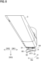
- FIGs. 7 and 8 are schematic plan views of an example handle 3.
- FIG. 9 is a diagram schematically illustrating a modification of the manipulation switch 6.
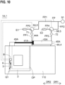
- FIG. 10 is a diagram schematically illustrating a door device 1A according to a first modification of the first embodiment for a machine tool.
- FIG. 11 is a diagram schematically illustrating a door device 1A according to a second modification of the first embodiment for a machine tool.
- FIGs. 12 and 13 illustrate example control flows of a motion of at least one switch valve 5.
- the door device 1A includes a door 2, the handle 3, at least one air cylinder 4, a fluid passage FP, the at least one switch valve 5, and the manipulation switch 6.
- the door 2 is slidable between a first position Q1 and a second position Q2.
- the first position Q1 (see FIG. 1 ) is a position at which the door 2 closes an opening OP of a housing 110, which defines the inner region of the machine tool.
- the second position Q2 (see FIG. 1 ) is a position at which the door 2 opens the opening OP.
- the direction from the first position Q1 toward the second position Q2 is defined as first direction DR1
- the direction from the second position Q2 toward the first position Q1 is defined as second direction DR2 .
- the door 2 is slidable in the first direction DR1 and slidable in the second direction DR2.
- the first direction DR1 and the second direction DR2 are directions parallel to horizontal direction.
- the handle 3 is provided at the door 2.
- the handle 3 may be a knob mounted on the door 2 or may be a depression provided in part of the door 2.
- the handle 3 is manipulated in the first direction DR1, and the door 2 is moved from the first position Q1 toward the second position Q2.
- the handle 3 is manipulated in the second direction DR2 (in other words, the direction opposite to the first direction DR1 ) , and the door 2 is moved from the second position Q2 toward the first position Q1.
- the at least one air cylinder 4 includes a first air chamber 41A. By receiving air supplied into the first air chamber 41A, the at least one air cylinder 4 applies a first assist force to the door 2 in the first direction DR1. In the example illustrated in FIG. 1 , air can be supplied into the first air chamber 41A from the air supply source 91.
- the at least one air cylinder 4 may include a second air chamber 43A. By receiving air supplied into the second air chamber 43A, the at least one air cylinder 4 applies a second assist force to the door 2 in the second direction DR2. In the example illustrated in FIG. 1 , air can be supplied into the second air chamber 43A from the air supply source 91.
- the at least one air cylinder 4 includes a first air cylinder 4A. It is the first air cylinder 4A that includes both the first air chamber 41A and the second air chamber 43A.
- the fluid passage FP includes a first fluid passage FP1.
- the first fluid passage FP1 connects the first air chamber 41A and the air supply source 91 to each other.
- the fluid passage FP may include a second fluid passage FP2.
- the second fluid passage FP2 connects the second air chamber 43A and the air supply source 91 to each other.
- part of the first fluid passage FP1 and part of the second fluid passage FP2 may be commonized (in the example illustrated in FIG. 1 , the part defined between the air supply source 91 and the switch valve 5 is common to the first fluid passage FP1 and the second fluid passage FP2).
- the first fluid passage FP1 and the second fluid passage FP2 may be completely independent of each other.
- the at least one switch valve 5 is provided at the fluid passage FP.
- the manipulation switch 6 switches the state of the at least one switch valve 5 between the first state exemplified in FIG. 1 and the second state exemplified in FIG. 2 .
- the door 2 is permitted to move in the first direction DR1 or the second direction DR2 without the first assist force.
- the at least one switch valve 5 fluidally connects the first air chamber 41A to a first atmosphere release hole E1, through which the air inside the first air chamber 41A is released.
- the at least one switch valve 5 may fluidally connect the second air chamber 43A to a second atmosphere release hole E2, through which the air inside the second air chamber 43A is released.
- the first assist force is applied to the door 2 in the first direction DR1.
- the at least one switch valve 5 fluidally connects the air supply source 91 and the first air chamber 41A to each other to cause air to be supplied into the first air chamber 41A.
- the worker manipulates the handle 3 in the first direction DR1
- the door 2 is moved from the first position Q1 toward the second position Q2 by a combination of the first assist force and the manipulation force of the worker.
- the at least one switch valve 5 may fluidally connect the second atmosphere release hole E2 and the second air chamber 43A to each other.
- the door device 1A for a machine tool is capable of switching the state of the at least one switch valve 5 between the first state and the second state.
- the door 2 In the first state, the door 2 is permitted to move in the first direction DR1 or the second direction DR2 without the first assist force.
- the first assist force is applied to the door 2 in the first direction DR1.
- the door device 1A for a machine tool is easy to use for both a worker who needs an assist force and a worker who does not need an assist force. More specifically, the door device 1A for a machine tool is configured with universal design taken into consideration to enable any worker to operate the door device and the machine tool while taking any posture and performing any type of work.
- the door device 1A according to the first embodiment for a machine tool includes the manipulation switch 6, which switches the state of the at least one switch valve 5 between the first state and the second state.
- the manipulation switch 6 which switches the state of the at least one switch valve 5 between the first state and the second state. This enables the worker to select the first state or the second state on the worker's own will. For example, a worker who does not need an assist force may select the first state to open the door 2 as if to open a usual door without assist functions, ensuring no or minimal degradation of work efficiency. Also, a worker who needs an assist force may select the second state to open the door 2 with a small degree of force.
- the air chamber of the air cylinder 4 is fluidally connected to an atmosphere release hole. This ensures that even if the motive power source is disconnected (more specifically, even if air can not be supplied from the air supply source 91 to the fluid passage FP), the door 2 can be moved freely in the first direction DR1 or the second direction DR2 .
- the second air chamber 43A of the air cylinder 4 may be fluidally connected to the second atmosphere release hole E2.
- the movement speed of the door 2 can be increased.
- the speed of air supply to the first air chamber 41A is less than a threshold value
- the presence of the mechanism to apply assist force does not interfere with the increase in the movement speed of the door 2.
- the worker is able to realize utilizing the assist force and quickly opening the door 2 simultaneously.
- the door 2 located at the first position Q1 can be moved to any desired position between the first position Q1 and the second position Q2 and stopped at the desired position. Also in the examples illustrated in FIGs. 1 and 2 , when the door 2 stopped at the desired position between the first position Q1 and the second position Q2 is moved again, the worker is able to move the door 2 without the first assist force. Also when the door 2 stopped at the desired position between the first position Q1 and the second position Q2 is moved again, the worker is able to move the door 2 by manipulating the manipulation switch 6 to utilize the first assist force.
- the first assist force may be smaller in degree than the force necessary for sliding the door 2.
- the first assist force may be set to a degree at which the door 2 can not be moved in the first direction DR1 without an additional force other than the first assist force.
- the position of the door 2 remains unchanged unless the worker applies a force to the handle 3.
- the first assist force may be set to a degree at which the door 2 can be moved at low speed in the first direction DR1 with the first assist force alone.
- the degree of the first assist force may be adjusted by, for example, changing a first set pressure of a first regulator 71, described later.
- the at least one air cylinder 4 (more specifically, the first air cylinder 4A) includes the second air chamber 43A.
- the at least one air cylinder 4 applies a second assist force to the door 2 in the second direction DR2.
- the fluid passage FP includes the second fluid passage FP2, which connects the second air chamber 43A and the air supply source 91 to each other.
- the manipulation switch 6 is capable of switching the state of the at least one switch valve 5 between the first state and a third state.
- the door 2 In the first state (see FIG. 1 ), the door 2 is permitted to move in the first direction DR1 or the second direction DR2 without the first assist force and the second assist force.
- the third state In the third state (see FIG. 1 ), the second assist force is applied to the door 2 in the second direction DR2 .
- the door 2 is permitted to move in the first direction DR1 or the second direction DR2 without the first assist force and the second assist force.
- the at least one switch valve 5 fluidally connects the first air chamber 41Ato the first atmosphere release hole E1, through which the air inside the first air chamber 41A is released.
- the at least one switch valve 5 also fluidally connects the second air chamber 43A to the second atmosphere release hole E2, through which the air inside the second air chamber 43A is released.
- the worker manipulates the handle 3 in the second direction DR2
- the door 2 is moved from the second position Q2 toward the first position Q1 without the second assist force.
- the second assist force is applied to the door 2 in the second direction DR2.
- the at least one switch valve 5 fluidally connects the first atmosphere release hole E1 and the first air chamber 41A to each other, and fluidally connects the air supply source 91 and the second air chamber 43A to each other.
- the worker manipulates the handle 3 in the second direction DR2
- the door 2 is moved from the second position Q2 toward the first position Q1 by a combination of the second assist force and the manipulation force of the worker.
- a worker who does not need an assist force may select the first state to close the door 2 as if to close a usual door without assist functions, ensuring no or minimal degradation of work efficiency. Also, a worker who needs an assist force may select the third state to close the door 2 with a small degree of force.
- the first air chamber 41A of the air cylinder 4 and the first atmosphere release hole E1 are fluidally connected to each other.
- the movement speed of the door 2 can be increased. This enables the worker to realize utilizing the assist force and quickly closing the door 2 simultaneously.
- the door 2 located at the second position Q2 can be moved to any desired position between the second position Q2 and the first position Q1 and stopped at the desired position. Also in the examples illustrated in FIGs. 3 and 4 , when the door 2 stopped at the desired position between the second position Q2 and the first position Q1 is moved again, the worker is able to move the door 2 without the first assist force and the second assist force. Also when the door 2 stopped at the desired position between the second position Q2 and the first position Q1 is moved again, the worker is able to move the door 2 in the first direction DR1 or the second direction DR2 by manipulating the manipulation switch 6 to use the first assist force or the second assist force .
- the second assist force may be smaller in degree than the force necessary for sliding the door 2.
- the second assist force may be set to a degree at which the door 2 can not be moved in the second direction DR2 without an additional force other than the second assist force.
- the second assist force may be set to a degree at which the door 2 can be moved at low speed in the second direction DR2 with the second assist force alone.
- the degree of second assist force may be adjusted by, for example, changing a second set pressure of a second regulator 72, described later.
- all manipulations of the manipulation switch 6 are performable independently of the manipulation of the handle 3.
- the manipulation switch 6 is not manipulated together with a manipulation of the handle 3. This provides a greater degree of freedom on the timing to switch the state between the first state and the second state (or the third state).
- the manipulation switch 6 may be manipulated to switch the state of the switch valve 5 from the first state to the assisted second state (or the assisted third state).
- the manipulation switch 6 may be manipulated (for example, fingers may be removed from the manipulation switch 6) to switch the state of the switch valve 5 from the second state or the third state to the no-assist first state.
- the manipulation switch 6 may be manipulated (for example, fingers may be removed from the manipulation switch 6) to switch the state of the switch valve 5 from the second state or the third state to the no-assist first state.
- the manipulation switch 6 is provided at the handle 3 to simultaneously realize holding the handle 3 by the hand and manipulating the manipulation switch 6 using a finger of the hand holding the handle 3 (for example, the thumb).
- a finger of the hand holding the handle 3 for example, the thumb.
- a direction perpendicular to a main surface 25 of the door 2 pointed from the inside of the door 2 toward the outside of the door 2 is defined as third direction DR3.
- the manipulation switch 6 is provided on a surface 31f of the handle 3.
- the surface 31f is on the third direction DR3 side of the handle 3 (in other words, its front-side surface).
- An alternative example is illustrated in FIG. 6 .
- a direction pointed perpendicularly upward is defined as fourth direction DR4.
- the manipulation switch 6 may be provided on a surface 31u of the handle 3.
- the surface 31u is on the fourth direction DR4 side of the handle 3 (in other words, the upper surface of the handle 3).
- an open area 3h is formed between the handle 3 and the door 2.
- the open area 3h is for four fingers of the worker to insert (the four fingers are forefinger, middle finger, ring finger, and little finger).
- the manipulation switch 6 is provided at the handle 3 to enable the worker to manipulate the manipulation switch 6 using the thumb of the worker with the remaining four fingers inserted in the open area 3h.
- a manipulation part 60 of the manipulation switch 6 (which part is manipulated by the worker) may be provided to protrude from the outer surface, 31, of the handle 3.
- the manipulation part 60 is easily manipulated.
- the manipulation part 60 protrudes further in the third direction DR3 than the surface 31f of the handle 3 which surface is on the third direction DR3 side of the handle 3.
- the manipulation part 60 protrudes further in the fourth direction DR4 than the surface 3 1u of the handle 3 which surface is on the fourth direction DR4 side of the handle 3.
- the handle 3 is a fixed handle mounted on the door 2 unmovably relative to the door 2.
- the handle 3 may be a movable handle mounted on the door 2 movably relative to the door 2 (for example, a handle swingable about a swing axis).
- the manipulation switch 6 includes a first manipulation part 61 and a second manipulation part 62.
- the first manipulation part 61 switches the state of the at least one switch valve 5 from the first state to the second state.
- the second manipulation part 62 switches the state of the at least one switch valve 5 from the first state to the third state.
- the first manipulation part 61 is provided further on the first direction DR1 side than the second manipulation part 62. In this case, by manipulating the first manipulation part 61, which is provided on the first direction DR1 side, the worker is able to apply the first assist force to the door 2 in the first direction DR1. Also, by manipulating the second manipulation part 62, which is provided on the second direction DR2 side, the worker is able to apply the second assist force to the door 2 in the second direction DR2.
- the manipulation part 60 which includes the first manipulation part 61 and the second manipulation part 62, is supported by a manipulation-part support member 64 in a manner in which the manipulation part 60 is swingable about a first axis AT1, which is perpendicular to the first direction DR1.
- a part of the manipulation-part support member 64 is embedded in the handle 3, and another part of the manipulation-part support member 64 protrudes from the outer surface 31 of the handle 3.
- the first axis AT1 is provided on the outside of the handle 3.
- the first axis AT1 may be provided to cross the handle 3.
- the manipulation part 60 located a default position tilts about the first axis AT1 (see FIG. 1 ) in a first rotation direction R1 toward a first manipulation position.
- the state of the at least one switch valve 5 is switched from the first state to the second state.
- the manipulation part 60 located at the default position tilts about the first axis AT1 in a second rotation direction R2 (which is the direction opposite to the first rotation direction R1 ) toward a second manipulation position.
- the state of the at least one switch valve 5 is switched from the first state to the third state.
- the manipulation part 60 is preferably configured to automatically return to the default position from the first manipulation position (or the second manipulation position).
- the manipulation part 60 is preferably biased by a biasing member such as a spring in a direction from the first manipulation position (or the second manipulation position) toward the default position.
- the manipulation part 60 automatically returns from the first manipulation position (or the second manipulation position) to the default position.
- the state of the switch valve 5 Upon returning of the manipulation part 60 of the manipulation switch 6 to the default position, the state of the switch valve 5 returns to the first state from the second state or the third state.
- the manipulation switch 6 is a switch that switches the state of the switch valve 5 only by manipulating the manipulation part 60.
- the manipulation switch 6 may be a switch that switches the state of the switch valve 5 by manipulating the manipulation part 60 and manipulating the handle 3.
- FIG. 9 upon pressing of the manipulation part 60 and application of a manipulation force to the handle 3 in the first direction DR1, the state of the switch valve 5 is switched from the first state to the second state.
- the state of the switch valve 5 is switched from the first state to the third state.
- the state of the switch valve 5 is kept at the first state.
- At least one manipulation of the manipulation switch 6 is performable independently of the manipulation of the handle 3. This provides a greater degree of freedom on the timing to switch the state between the first state and the second state (or the third state).
- the manipulation switch 6 may be manipulated (for example, fingers may be removed from the manipulation switch 6) to switch the state of the switch valve 5 from the second state or the third state to the no-assist first state.
- a detection as to whether a manipulation force is being applied to the handle 3 in the first direction DR1 may be performed by a first sensor 66a (an example of which is a first proximity sensor).
- the first sensor 66a detects a movement of the handle 3 relative to the door 2.
- a detection as to whether a manipulation force is being applied to the handle 3 in the second direction DR2 may be performed by a second sensor 66b (an example of which is a second proximity sensor).
- the second sensor 66b detects a movement of the handle 3 relative to the door 2.
- a detection as to whether a manipulation force is being applied to the handle 3 in the first direction DR1 or the second direction DR2 may be performed by a load sensor embedded in the handle 3.
- the state of the switch valve 5 upon release of pressing of the manipulation part 60 when the state of the switch valve 5 is the second state or the third state, the state of the switch valve 5 returns to the first state.
- the state of the switch valve 5 may be kept at the second state or the third state even if the pressing of the manipulation part 60 is released when the state of the switch valve 5 is the second state or the third state. In other words, the state of the switch valve 5 may be kept at the second state or the third state unless the manipulation part 60 is positively manipulated.
- the default state of the at least one switch valve 5 is preferably the first state. More specifically, in a power-source disconnected state in which no power is supplied to the switch valve 5, the state of the switch valve 5 is preferably kept at the first state. In this case, when power is off (for example, at the time of power failure), the door 2 can be moved freely in the first direction DR1 or the second direction DR2 .
- An example of the switch valve 5 is a solenoid valve.
- the switch valve 5 includes a first solenoid 51 and a second solenoid 52.
- the first solenoid 51 is electrically conducted.
- the state of the switch valve 5 Upon electrical conduction of the first solenoid 51, the state of the switch valve 5 is switched from the first state to the second state (see FIG. 1 ). By performing a second manipulation to force the manipulation part 60 of the manipulation switch 6 toward the second manipulation position, the second solenoid 52 is electrically conducted. Upon electrical conduction of the second solenoid 52, the state of the switch valve 5 is switched from the first state to the third state (see FIG. 1 ). When the manipulation part 60 of the manipulation switch 6 is at the default position, the state of the switch valve 5 is kept at the first state.
- the switching between the first state and the second state and the switching between the first state and the third state are performed by a single switch valve 5. More specifically, the switch valve 5 realizes the following. (1) As exemplified in FIG. 1 , the switch valve 5 realizes a no-assist state in which the first air chamber 41A and the first atmosphere release hole E1 are fluidally connected to each other, and the second air chamber 43A and the second atmosphere release hole E2 are fluidally connected to each other. (2) As exemplified in FIG.
- the switch valve 5 realizes a first assist state in which the first air chamber 41A and the air supply source 91 are fluidally connected to each other, and the second air chamber 43A and the second atmosphere release hole E2 are fluidally connected to each other.
- the switch valve 5 realizes a second assist state in which the first air chamber 41A and the first atmosphere release hole E1 are fluidally connected to each other, and the second air chamber 43A and the air supply source 91 are fluidally connected to each other.
- the switching between the first state and the second state may be performed by a plurality of switch valves 5.
- the at least one switch valve 5 includes a first switch valve 5A and a second switch valve 5B.
- the first switch valve 5A is provided at the first fluid passage FP1, which connects the first air chamber 41A and the air supply source 91 to each other.
- the second switch valve 5B is provided at the second fluid passage FP2, which connects the second air chamber 43A and the air supply source 91 to each other.
- the first switch valve 5A and the second switch valve 5B realize the first state, in which the door 2 is permitted to move in the first direction DR1 or the second direction DR2 without the first assist force and the second assist force. More specifically, in the first state, the first switch valve 5A maintains a fluid connection state between the first air chamber 41A and the first atmosphere release hole E1. The second switch valve 5B maintains a fluid connection state between the second air chamber 43A and the second atmosphere release hole E2. Assume a case where the state of the plurality of switch valves 5, which include the first switch valve 5A and the second switch valve 5B, is the first state. In this case, if the worker manipulates the handle 3 in the first direction DR1 (or the second direction DR2), the door 2 is moved in the first direction DR1 (or the second direction DR2 ) without the first assist force.
- the first switch valve 5A and the second switch valve 5B realize the second state, in which the first assist force is applied to the door in the first direction DR1. More specifically, in the second state, the first switch valve 5A fluidally connects the first air chamber 41A to the air supply source 91 to cause air to be supplied into the first air chamber 41A.
- the second switch valve 5B fluidally connects the second air chamber 43A to the second atmosphere release hole E2.
- the state of the plurality of switch valves 5, which include the first switch valve 5A and the second switch valve 5B is the second state. In this case, if the worker manipulates the handle 3 in the first direction DR1, the door 2 is moved in the first direction DR1 by a combination of the first assist force and the manipulation force of the worker.
- the first switch valve 5A and the second switch valve 5B realize the third state, in which the second assist force is applied to the door in the second direction DR2 . More specifically, in the third state, the first switch valve 5A fluidally connects the first air chamber 41Ato the first atmosphere release hole E1, and the second switch valve 5B fluidally connects the second air chamber 43A to the air supply source 91 to cause air to be supplied into the second air chamber 43A.
- the state of the plurality of switch valves 5, which include the first switch valve 5A and the second switch valve 5B is the third state. In this case, if the worker manipulates the handle 3 in the second direction DR2, the door 2 is moved in the second direction DR2 by a combination of the second assist force and the manipulation force of the worker.
- the at least one air cylinder 4 includes the first air cylinder 4A.
- the first air cylinder 4A includes the first air chamber 41A, the second air chamber 43A, and a first piston 44A.
- the first piston 44A is provided between the first air chamber 41A and the second air chamber 43A.
- the first air cylinder 4A may include a first rod 45A.
- the first rod 45A is connected to the first piston 44A.
- the first air cylinder 4A includes the first air chamber 41A, which is connectable to the air supply source 91 via the first fluid passage FP1, and the second air chamber 43A, which is connectable to the air supply source 91 via the second fluid passage FP2.
- the first piston 44A is driven by the pressure difference between the first air chamber 41A and the second air chamber 43A.
- the first rod 45A is movable together with the first piston 44A.
- the first rod 45A is directly connected to the door 2, or is indirectly connected to the door 2 via a mechanical transfer member such as a belt, a wire, a cable, and a gear.
- the state of the at least one switch valve 5 when the state of the at least one switch valve 5 is the first state, the first air chamber 41A and the first atmosphere release hole E1 are fluidally connected to each other, and the second air chamber 43A and the second atmosphere release hole E2 are fluidally connected to each other.
- This configuration enables the first piston 44A and the first rod 45A to move relative to a body 40A of the first air cylinder 4A with substantially no resistance in response to a movement of the door 2 in the first direction DR1 or the second direction DR2.
- FIG. 1 when the state of the at least one switch valve 5 is the first state, the first air chamber 41A and the first atmosphere release hole E1 are fluidally connected to each other, and the second air chamber 43A and the second atmosphere release hole E2 are fluidally connected to each other.
- the first air chamber 41A and the air supply source 91 are fluidally connected to each other, and the second air chamber 43A and the second atmosphere release hole E2 are fluidally connected to each other.
- the first assist force is applied to the door 2 in the first direction DR1.
- the second air chamber 43A and the air supply source 91 are fluidally connected to each other, and the first air chamber 41A and the first atmosphere release hole E1 are fluidally connected to each other.
- the second assist force is applied to the door 2 in the second direction DR2 .
- the number of air cylinders to apply the first assist force or the second assist force to the door 2 is one.
- the number of air cylinders to apply the first assist force or the second assist force to the door 2 may be two or more.
- the at least one air cylinder 4, which applies the first assist force or the second assist force to the door 2 may include the first air cylinder 4A and a second air cylinder 4B.
- the first air cylinder 4A includes the first air chamber 41A; a third air chamber 41B; the first piston 44A, which is provided between the first air chamber 41A and the third air chamber 41B; and the first rod 45A, which is connected to the first piston 44A.
- the second air cylinder 4B includes the second air chamber 43A; a fourth air chamber 43B; a second piston 44B, which is provided between the second air chamber 43A and the fourth air chamber 43B; and a second rod 45B, which is connected to the second piston 44B.
- the first air cylinder 4A includes the first air chamber 41A, which is connectable to the air supply source 91 via the first fluid passage FP1.
- the second air cylinder 4B includes the second air chamber 43A, which is connectable to the air supply source 91 via the second fluid passage FP2.
- the first air chamber 41A is provided at the first air cylinder 4A.
- the first air chamber 41A is connected to the air supply source 91 at the time when the first assist force is applied to the door 2 in the first direction DR1.
- the second air chamber 43A is provided at the second air cylinder 4B.
- the second air chamber 43A is connected to the air supply source 91 at the time when the second assist force is applied to the door 2 in the second direction DR2.
- the first air chamber 41A and the second air chamber 43A may be provided at a single first air cylinder 4A.
- the first air chamber 41A and the second air chamber 43A may be provided separately at a plurality of air cylinders (4A and 4B).
- the fluid passage FP includes the first fluid passage FP1, which fluidally connects the first air chamber 41A and the air supply source 91 to each other.
- the switch valve 5 is provided at the first fluid passage FP1.
- the first switch valve 5A is provided at the first fluid passage FP1.
- the fluid passage FP includes the second fluid passage FP2, which fluidally connects the second air chamber 43A and the air supply source 91 to each other.
- the switch valve 5 is provided at the second fluid passage FP2.
- the second switch valve 5B is provided at the second fluid passage FP2.
- the fluid passage FP includes a third fluid passage FP3.
- the third fluid passage FP3 fluidally connects the first air chamber 41A and the first atmosphere release hole E1 to each other.
- the switch valve 5 is provided at the third fluid passage FP3.
- the first switch valve 5A is provided at the third fluid passage FP3.
- Part of the third fluid passage FP3 and part of the first fluid passage FP1 may be commonized (for example, the fluid passage between the first air chamber 41A and the switch valve 5 is commonized).
- the fluid passage FP includes a fourth fluid passage FP4.
- the fourth fluid passage FP4 fluidally connects the second air chamber 43A and the second atmosphere release hole E2 to each other.
- the switch valve 5 is provided at the fourth fluid passage FP4.
- the second switch valve 5B is provided at the fourth fluid passage FP4.
- Part of the fourth fluid passage FP4 and part of the second fluid passage FP2 may be commonized (for example, the fluid passage between the second air chamber 43A and the switch valve 5 is commonized).
- the second atmosphere release hole E2 is an atmosphere release hole different from the first atmosphere release hole E1.
- the second atmosphere release hole E2 and the first atmosphere release hole E1 may be identical to each other.
- the fluid passage FP includes a fifth fluid passage FP5 and a sixth fluid passage FP6.
- the fifth fluid passage FP5 fluidally connects the third air chamber 41B and a third atmosphere release hole E3 to each other.
- the sixth fluid passage FP6 fluidally connects the fourth air chamber 43B and a fourth atmosphere release hole E4 to each other.
- the air supply source 91 that supplies air to the first air chamber 41A is identical to the air supply source 91 that supplies air to the second air chamber 43A.
- the air supply source that supplies air to the first air chamber 41A may be different from the air supply source that supplies air to the second air chamber 43A.
- the number of air supply sources included in the door device 1A may be two or more.
- the air supply source 91 may be an air pump or a compressor.
- the door device 1A includes the first regulator 71, which adjusts the pressure of the air supplied to the first air chamber 41A.
- the first regulator 71 is provided at the first fluid passage FP1 (more specifically, the fluid passage between the switch valve 5 and the first air chamber 41A).
- the first regulator 71 adjusts the first set pressure, which is the pressure of the air supplied to the first air chamber 41A.
- the first regulator 71 may be a reverse regulator that permits air to flow from the first air chamber 41A toward the switch valve 5 (in other words, a regulator with a reverse flow function).
- the door device 1A includes the second regulator 72, which adjusts the pressure of the air supplied to the second air chamber 43A.
- the second regulator 72 is provided at the second fluid passage FP2 (more specifically, the fluid passage between the switch valve 5 and the second air chamber 43A).
- the second regulator 72 adjusts the second set pressure, which is the pressure of the air supplied to the second air chamber 43A.
- the second set pressure may be set to the value of the first set pressure, or may be set to a value different from the first set pressure.
- the second regulator 72 may be a reverse regulator that permits air to flow from the second air chamber 43A toward the switch valve 5 (in other words, a regulator with a reverse flow function).
- the door device 1A may include the first regulator 71 and the second regulator 72 different from the first regulator 71.
- the assist force necessary for the opening motion of the door 2 may be different from the assist force necessary for the closing motion of the door 2.
- the door device 1A including the first regulator 71 and the second regulator 72 is capable of individually setting assist forces necessary for different motions.
- the door device 1A may include a controller 8.
- the controller 8 controls a motion of the at least one switch valve 5.
- the controller 8 receives, from the manipulation switch 6, a manipulation detection signal indicating that the manipulation switch 6 has been manipulated. Then, the controller 8 transmits a control signal to the at least one switch valve 5.
- the manipulation switch 6 transmits a first manipulation detection signal to the controller 8.
- the controller 8 Upon receipt of the first manipulation detection signal, which indicates that the manipulation switch 6 has been subjected to the first manipulation, the controller 8 transmits a first control signal to the at least one switch valve 5 to switch the state of the at least one switch valve 5 from the first state to the second state.
- the first control signal may include a control command to electrically conduct the first solenoid 51.
- the first control signal may be a current itself to electrically conduct the first solenoid 51.
- the controller 8 may return the state of the at least one switch valve 5 from the second state to the first state. In this case, the first assist force is prevented from being applied continuously due to, for example, an abnormality in the manipulation switch 6.
- the controller 8 may emit an alarm. The emission of an alarm may include generation of warning sound, lighting of a warning lamp, or display of a warning message.
- the manipulation switch 6 transmits a second manipulation detection signal to the controller 8.
- the controller 8 transmits a second control signal to the at least one switch valve 5 to switch the state of the at least one switch valve 5 from the first state to the third state.
- the second control signal may include a control command to electrically conduct the second solenoid 52.
- the second control signal may be a current itself to electrically conduct the second solenoid 52.
- the controller 8 may return the state of the at least one switch valve 5 from the third state to the first state.
- the second assist force is prevented from being applied continuously due to, for example, an abnormality in the manipulation switch 6.
- the controller 8 may emit an alarm.
- the second threshold is, for example, set to a value identical to the first threshold.
- the signal from the manipulation switch 6 to the controller 8 is discontinued.
- the manipulation switch 6 may transmit a third manipulation detection signal to the controller 8.
- the controller 8 transmits a third control signal to the at least one switch valve 5.
- the controller 8 may stop transmitting the control signal to the at least one switch valve 5.
- the at least one switch valve 5 Upon receipt of the third control signal (or upon disconnection of the control signal), the at least one switch valve 5 returns the state of the at least one switch valve 5 to the first state.
- a motion of the at least one switch valve 5 is controlled by the controller 8.
- a manipulation of the manipulation switch 6 may directly influence a motion of the switch valve 5.
- the manipulation switch 6 and the switch valve 5 may be electrically connected to each other via an electric circuit, and a manipulation of the manipulation switch 6 may change the state of the electric circuit.
- the first solenoid 51 or the second solenoid 52 of the switch valve 5 may be driven.
- FIGs. 12 and 13 illustrate example control flows of a motion of the at least one switch valve 5.
- the controller 8 determines whether the manipulation switch 6 has been subjected to a first manipulation or a second manipulation. Upon receipt of a first manipulation detection signal from the manipulation switch 6, the controller 8 determines that the manipulation switch 6 has been subjected to the first manipulation, and electrically conducts the first solenoid 51 (second step ST2). Upon receipt of a second manipulation detection signal from the manipulation switch 6, the controller 8 determines that the manipulation switch 6 has been subjected to the second manipulation, and electrically conducts the second solenoid 52 (eighth step ST8).
- First step ST1 may be performable only when the door 2 is in an unlocked state. In other words, when the door 2 is in a locked state, first step ST1 may be prohibited.
- the state of the at least one switch valve 5 is switched from the first state to the second state.
- the at least one air cylinder 4 applies a first assist force to the door 2 in the first direction DR1.
- the controller 8 determines whether the continuation period of time of the first manipulation is a first threshold or less. In other words, the controller 8 determines whether the continuation period of time of receipt of the first manipulation detection signal is the first threshold or less.
- the procedure proceeds to sixth step ST6.
- the controller 8 releases the electrical conduction of the first solenoid 51 (fourth step ST4).
- the state of the at least one switch valve 5 returns to the first state from the second state.
- the controller 8 may emit an alarm (fifth step ST5).
- the controller 8 determines whether the first manipulation has ended. In other words, the controller 8 determines whether the receipt of the first manipulation detection signal has discontinued. When the first manipulation has not ended yet, the procedure returns to third step ST3. When the first manipulation has ended, the controller 8 releases the electrical conduction of the first solenoid 51 (seventh step ST7) to end the application of the first assist force. Then, the controller 8 may perform first step ST1 again.
- step ST8 upon electrical conduction of the second solenoid 52, the state of the at least one switch valve 5 is switched from the first state to the third state. As a result, the at least one air cylinder 4 applies a second assist force to the door 2 in the second direction DR2 .
- the controller 8 determines whether the continuation period of time of the second manipulation is a second threshold or less. In other words, the controller 8 determines whether the continuation period of time of receipt of the second manipulation detection signal is the second threshold or less.
- the procedure proceeds to twelfth step ST12.
- the controller 8 releases the electrical conduction of the second solenoid 52 (tenth step ST10).
- the state of the at least one switch valve 5 returns to the first state from the third state.
- the controller 8 may emit an alarm (eleventh step ST11).
- the controller 8 determines whether the second manipulation has ended. In other words, the controller 8 determines whether the receipt of the second manipulation detection signal has discontinued. When the second manipulation has not ended yet, the procedure returns to ninth step ST9. When the second manipulation has ended, the controller 8 releases the electrical conduction of the second solenoid 52 (thirteenth step ST13) to end the application of the second assist force. Then, the controller 8 may perform first step ST1 again.
- the controller 8 Upon receipt of the first manipulation signal from the manipulation switch 6, the controller 8 switches the state of the at least one switch valve 5 from the first state to the second state. As a result, the at least one air cylinder 4 applies the first assist force to the door 2 in the first direction DR1. Then, upon ending of the receipt of the first manipulation signal, the controller 8 may switch the state of the at least one switch valve 5 to cause the at least one air cylinder 4 to apply a braking force to the door 2 in the second direction DR2 . More specifically, upon ending of the receipt of the first manipulation signal, the controller 8 may switch the state of the switch valve 5 from the second state to the third state.
- the braking force may be applied in the second direction DR2 after, for example, the electrical conduction of the first solenoid 51 is released (in other words, after seventh step ST7). More specifically, after the electrical conduction of the first solenoid 51 is released, the controller 8 electrically conducts the second solenoid 52 only for the predetermined first setting period of time. As a result, air is supplied from the air supply source 91 into the second air chamber 43A, causing the braking force to be applied to the door 2 in the second direction DR2 . Upon passing of the first setting period of time, the controller 8 releases the electrical conduction of the second solenoid 52.
- the controller 8 Upon receipt of the second manipulation signal from the manipulation switch 6, the controller 8 switches the state of the at least one switch valve 5 from the first state to the third state. As a result, the at least one air cylinder 4 applies the second assist force to the door 2 in the second direction DR2 . Then, upon ending of the receipt of the second manipulation signal, the controller 8 may switch the state of the at least one switch valve 5 to cause the at least one air cylinder 4 to apply a braking force the door 2 in the first direction DR1. More specifically, upon ending of the receipt of the second manipulation signal, the controller 8 may switch the state of the switch valve 5 from the third state to the second state.
- the braking force in the first direction DR1 may be applied after, for example, the electrical conduction of the second solenoid 52 is released (in other words, after thirteenth step ST13). More specifically, after the electrical conduction of the second solenoid 52 is released, the controller 8 electrically conducts the first solenoid 51 only for the predetermined second setting period of time. As a result, air is supplied from the air supply source 91 into the first air chamber 41A, causing the braking force to be applied to the door 2 in the first direction DR1. Upon passing of the second setting period of time, the controller 8 releases the electrical conduction of the first solenoid 51. It is to be noted that an example of the second setting period of time is identical in length to the first setting period of time.
- FIGs. 14 to 17 the door device 1B according to the second embodiment for a machine tool will be described.
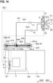
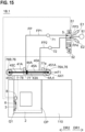
- FIGs. 14 to 16 are diagrams schematically illustrating the door device 1B according to the second embodiment for a machine tool.
- FIG. 17 is a diagram schematically illustrating an example installation of a movable pulley 76 and/or the first air cylinder 4A.
- the door device 1B according to the second embodiment for a machine tool is different from the door device 1A according to the first embodiment for a machine tool in that the door device 1B includes the movable pulley 76.
- the door device 1B according to the second embodiment for a machine tool is similar to the door device 1A according to the first embodiment for a machine tool.
- the door device 1B includes the following. (1) A door 2. The door 2 is slidable between the first position Q1 and the second position Q2. The first position Q1 is a position at which the door 2 closes the opening OP of the housing 110, which defines the inner region of the machine tool. The second position Q2 is a position at which the door opens the opening OP. (2) A handle 3. The handle 3 is provided at the door 2. (3) At least one air cylinder 4. The at least one air cylinder 4 includes the first air chamber 41A and is configured to, by receiving air into the first air chamber 41A, apply a first assist force to the door 2 in a first direction DR1 from the first position toward the second position.
- the fluid passage FP includes a first fluid passage FP1.
- the first fluid passage FP1 connects the first air chamber 41A and the air supply source 91 to each other.
- the at least one switch valve 5 is provided at the fluid passage FP.
- the manipulation switch 6 is configured to switch the state of the at least one switch valve 5 between the first state and the second state.
- the first state is a state in which the door 2 is permitted to move without the first assist force in the first direction DR1 or the second direction DR2 from the second position toward the first position.
- the second state is a state in which the first assist force is applied to the door 2 in the first direction DR1.
- the door device 1B according to the second embodiment for a machine tool provides effects similar to the effects provided by the door device 1A according to the first embodiment for a machine tool.
- the at least one air cylinder 4 includes the first piston 44A, which is driven by the air supplied into the first air chamber 41A. More specifically, the at least one air cylinder 4 includes the first air cylinder 4A.
- the first air cylinder 4A includes the first air chamber 41A, the second air chamber 43A, and the first piston 44A, which is provided between the first air chamber 41A and the second air chamber 43A.
- the state of the at least one switch valve 5 is the first state
- the first air chamber 41A and the first atmosphere release hole E1 are fluidally connected to each other
- the second air chamber 43A and the second atmosphere release hole E2 are fluidally connected to each other.
- FIG. 15 when the state of the at least one switch valve 5 is the second state, the first air chamber 41A and the air supply source 91 are fluidally connected to each other, and the second air chamber 43A and the second atmosphere release hole E2 are fluidally connected to each other.
- the door device 1B includes the movable pulley 76.
- the movable pulley 76 converts a first displacement of the door 2 into a second displacement of the first piston 44A.
- the second displacement is smaller than the first displacement.
- the second displacement is 1/2 of the first displacement.
- the door device 1B includes the movable pulley 76.
- the movement stroke of the first piston 44A is small as compared with the movement stroke of the door 2.
- the first air cylinder 4A can be made shorter in length.
- a first air cylinder 4A with a smaller diameter in other words, a first piston 44A with a smaller diameter
- the fact that the first piston 44A has a smaller diameter means that the first piston 44A has a small area that contacts the air inside the air chambers (41A and 43A) (that is, the first piston 44A has a small pressure receiving area).
- the fact that the first piston 44A has a small pressure receiving area means that the assist force applied to the door 2 is less variable relative to changes in the internal pressure of the air chambers.
- the pressure receiving area of the first piston 44A can be made small. As a result, a lower level of accuracy is required when the regulators (71 and 72) adjust pressure.
- the movable pulley 76 includes a first movable pulley 76A.
- the first movable pulley 76A is supported by the first rod 45A (more specifically, a first end portion 451A of the first rod 45A) and rotatable about a first rotation axis AX1.
- a second end portion of the first rod 45A is connected to, for example, the first piston 44A.
- the state of the at least one switch valve 5 is the second state.
- the first air chamber 41A is fluidally connected to the air supply source 91.
- a first force F1 is applied to the first piston 44A, the first rod 45A, and the first movable pulley 76A in the first direction DR1.
- the door device 1B includes a flexible member 77.
- the flexible member 77 is guided by the first movable pulley 76A.
- the door 2 is directly or indirectly connected to the flexible member 77.
- the flexible member 77 upon application of the first force F1 to the first movable pulley 76A in the first direction DR1, the flexible member 77 applies, to the door 2, a first assist force that is half the degree of the first force F1.
- the door 2 is moved by the first displacement in the first direction DR1.
- the first movable pulley 76A, the first rod 45A, and the first piston 44A are moved in the first direction DR1 by a second displacement that is half the degree of the first displacement.
- the flexible member 77 may be a linear material such as a wire and a cable, or may be a strip-shaped material such as a belt.
- a first end portion 77a of the flexible member 77 is connected to the body 40A (in other words, the cylinder part) of the first air cylinder 4A.
- the first end portion 77a of the flexible member 77 may be connected to the housing 110.
- the movable pulley 76 includes a second movable pulley 76B.
- the second movable pulley 76B is supported by a second rod 45C (more specifically, a first end portion 451C of the second rod 45C) and rotatable about a second rotation axis AX2.
- a second end portion of the second rod 45C is connected to, for example, the first piston 44A.
- the state of the at least one switch valve 5 is the third state.
- the second air chamber 43A is fluidally connected to the air supply source 91.
- a second force F2 is applied to the first piston 44A, the second rod 45C, and the second movable pulley 76B in the second direction DR2 .
- the door device 1B includes a flexible member 77.
- the flexible member 77 is guided by the second movable pulley 76B.
- the door 2 is directly or indirectly connected to the flexible member 77.
- the flexible member 77 applies, to the door 2, a second assist force that is half the degree of the second force F2.
- the door 2 is moved by a third displacement in the second direction DR2 .
- the second movable pulley 76B, the second rod 45C, and the first piston 44A are moved in the second direction DR2 by a fourth displacement that is half the degree of the third displacement.
- a second end portion 77b of the flexible member 77 is connected to the body 40A of the first air cylinder 4A.
- the second end portion 77b of the flexible member 77 may be connected to the housing 110.
- the second movable pulley 76B may be omitted, or the second movable pulley 76B may be replaced with a fixed pulley.
- the at least one air cylinder 4 includes the first air cylinder 4A.
- the number of air cylinders 4 included in the door device 1B is one.
- the number of air cylinders 4 included in the door device 1B may be two or more.
- the at least one air cylinder 4 may include the first air cylinder 4A and the second air cylinder 4B.
- the first air cylinder 4A is referred to as "double rod cylinder" in English. More specifically, the first air cylinder 4A includes the first rod 45A, which protrudes from a first end portion of the body 40A in the first direction DR1 and the second rod 45C, which protrudes from a second end portion of the body 40A in the second direction DR2 . At a leading end portion of the first rod 45A, the first movable pulley 76A is provided. At a leading end portion of the second rod 45C, the second movable pulley 76B is provided. In the example illustrated in FIG.
- the flexible member 77 is guided by both the first movable pulley 76A and the second movable pulley 76B.
- the first movable pulley 76A is provided at the leading end portion of the first rod 45A
- the second movable pulley 76B is provided at the leading end portion of the second rod 45C.
- the rotation axis of the movable pulley 76 is parallel to the vertical direction. More specifically, the first rotation axis AX1 of the first movable pulley 76A is parallel to the vertical direction, and the second rotation axis AX2 of the second movable pulley 76B is parallel to the vertical direction.
- This configuration makes the size of the movable pulley 76 compact in its height direction, and makes the entire size of the mechanism of applying assist force compact in the height direction of the mechanism.
- the movable pulley 76 is provided on the ceiling, 111, of the housing 110, which defines the inner region of the machine tool (more specifically, on the upper surface, 11 1u, of the ceiling 111).
- the configuration in which the rotation axis of the movable pulley 76 is parallel to the vertical direction makes the entire size of the machine tool compact in its height direction.
- the first air cylinder 4A is provided on the ceiling 111 of the housing 110, which defines the inner region of the machine tool (more specifically, the upper surface 11 1u of the ceiling 111). In this case, it is not necessary to increase the size of the housing 110 in plan view even though the first air cylinder 4A is added. Also in the above case, it is easy to provide an existing machine tool with a mechanism of applying assist force (such as the first air cylinder 4A).
- the body 40A of the first air cylinder 4A (in other words, the cylinder part) is fixed to the ceiling 111.
- the arrangement of the first air cylinder 4A in FIG. 17 may be employed in the first embodiment.
- the body 40A of the first air cylinder 4A is provided not to overlap the movable pulley 76 in plan view. More specifically, the body 40A of the first air cylinder 4A and the movable pulley 76 (more specifically, the first movable pulley 76A and the second movable pulley 76B) are aligned on a single horizontal surface. This configuration makes the entire size of the mechanism of applying assist force compact in the height direction of the mechanism. In the example illustrated in FIG. 17 , the first movable pulley 76A, the body 40A of the first air cylinder 4A, and the second movable pulley 76B are aligned on one line parallel to the horizontal surface.
- the door device 1B includes a first connection member 78.
- the first connection member 78 connects the door 2 and the flexible member 77 to each other.
- the first connection member 78 is provided not to overlap the first air cylinder 4A in plan view. More specifically, the first air cylinder 4A and the first connection member 78 are aligned on the single horizontal surface. This configuration makes the entire size of the mechanism of applying assist force compact in the height direction of the mechanism.
- the direction from the rear surface of the housing 110 toward the opening OP of the housing 110 is defined as the third direction DR3 .
- the first connection member 78 is provided on the third direction DR3 side of the first air cylinder 4A.
- the door device 1B may include at least one second connection member 79.
- the at least one second connection member 79 connects the ceiling 111 of the housing 110 and the flexible member 77 to each other.
- the first air cylinder 4A and the at least one second connection member 79 are aligned on the single horizontal surface. While in the example illustrated in FIG. 17 the number of second connection members 79 is two, the number of second connection members 79 may be one or three or more. Also, in cases including a case where the flexible member 77 is an endless member, the second connection member 79 may be omitted.
- the number of doors 2 is one.
- the number of doors 2 may be two or more.
- the door 2 may include a first door and a second door.
- the first door is movable in the first direction DR1 to open one part of the opening OP.
- the second door is movable in the second direction DR2 , which is opposite to the first direction DR1, to open an other part of the opening OP.
- each of the first door and the second door may be provided with a mechanism of applying assist force.
- the door 2 may also be a sliding door that includes a first panel and a second panel connected to the first panel and slidable relative to the first panel.
- the first panel and the second panel may be superimposed on each other; when the opening OP is closed, the second panel may be developed relative to the first panel to diminish the region over which the first panel and the second panel overlap.
- the second panel may be provided with the handle 3 with a mechanism of applying assist force to the second panel. It is to be noted that in the first or second embodiment, the number of doors 2 or the kind of the door 2 will not be limited to the above-described examples and is open to any other examples.
- the opening OP of the housing 110 includes a first opening OP1 and a second opening OP2.
- the first opening OP1 is formed on a front wall 112 of the housing 110.
- the second opening OP2 is formed on the ceiling 111 of the housing 110.
- the door 2 includes a first plate 21 and a second plate 22.
- the first plate 21 closes the first opening OP1 of the front wall 112 of the housing 110.
- the second plate 22 closes the second opening OP2 of the ceiling 111 of the housing 110.
- the door 2 has an approximately L-shaped cross-section perpendicular to the first direction DR1. It is to be noted that in the first or second embodiment, the shape of the door 2 will not be limited to the above-described examples and is open to any other examples.
- the door device 1B may include a support member 95.
- the support member 95 supports the at least one air cylinder 4, the movable pulley 76, and the first connection member 78. In this case, by mounting the support member 95 on the ceiling 111, the at least one air cylinder 4, the movable pulley 76, and the first connection member 78 can be provided on the ceiling 111.
- the at least one switch valve 5 may have a configuration similar to the configuration of the at least one switch valve 5 according to the first embodiment.
- the number of switch valves 5 included in the door device 1B is one.
- the number of switch valves 5 included in the door device 1B may be two or more.
- the at least one switch valve 5 may include the first switch valve 5A and the second switch valve 5B.
- FIG. 18 is a schematic perspective view of the machine tool 100 according to the third embodiment.
- the machine tool 100 includes a machining device 120, a workpiece support device 130, the housing 110, and the door device 1.
- the door device 1 may be the door device 1A according to the first embodiment, the door device 1B according to the second embodiment, or any other door device.
- the door device 1 includes the following. (1) A door 2.
- the door 2 is slidable between the first position Q1 and the second position Q2.
- the first position Q1 is a position at which the door 2 closes the opening OP of the housing 110.
- the second position Q2 is a position at which the door opens the opening OP.
- the handle 3 is provided at the door 2.
- the at least one air cylinder 4 includes the first air chamber 41A and is configured to, by receiving air into the first air chamber 41A, apply a first assist force to the door 2 in a first direction DR1 from the first position toward the second position.
- the fluid passage FP includes a first fluid passage FP1.
- the first fluid passage FP1 connects the first air chamber 41A and the air supply source 91 to each other.
- the at least one switch valve 5 is provided at the fluid passage FP.
- the manipulation switch 6 is configured to switch the state of the at least one switch valve 5 between the first state and the second state.
- the first state is a state in which the door 2 is permitted to move without the first assist force in the first direction DR1 or the second direction DR2 from the second position toward the first position.
- the second state is a state in which the first assist force is applied to the door 2 in the first direction DR1.
- the machining device 120 machines a workpiece.
- the machining device 120 is capable of holding a tool for machining the workpiece.
- the workpiece support device 130 supports the workpiece machined by the machining device 120.
- the housing 110 surrounds the machining device 120 and the workpiece support device 130.
- the housing 110 includes the opening OP. Prior to the machining performed by the machining device 120, the workpiece is inserted into the housing 110 through the opening OP. After the machining performed by the machining device 120 ends, the workpiece is taken through the opening OP.
- Support member 100 ... Machine tool, 110 ... Housing, 111 ... Ceiling, 111u ... Upper surface, 112 ... Front wall, 120 ... Machining device, 130 ... Workpiece support device, 451A ... First end portion, 451C ... First end portion, E1 ... First atmosphere release hole, E2 ... Second atmosphere release hole, E3 ... Third atmosphere release hole, E4 ... Fourth atmosphere release hole, FP ... Fluid passage, FP 1 ... First fluid passage, FP2 ... Second fluid passage, FP3 ... Third fluid passage, FP4 ... Fourth fluid passage, FP5 ... Fifth fluid passage, FP6 ... Sixth fluid passage, OP ... Opening, OP1 ... First opening, OP2 ... Second opening
Landscapes
- Engineering & Computer Science (AREA)
- Mechanical Engineering (AREA)
- Auxiliary Devices For Machine Tools (AREA)
- Power-Operated Mechanisms For Wings (AREA)
Abstract
Description
- The present invention relates to a door device for a machine tool, and a machine tool.
- Aid devices to aid opening and closing of doors of machine tools are known.
- As a related technique,
patent literature 1 discloses a door open-close aid device. The door open-close aid device recited inpatent literature 1 includes a fluid pressure source, a fluid pressure actuator that applies an aid driving force to aid an open-close operation performed by a manual force, adjusting means for changing and/or adjusting the amount of flow of a working fluid supplied from the fluid pressure source to the fluid pressure actuator and changing and/or adjusting the direction or pressure of the working fluid, and a door handle mounted on the openable-closable door in a manner in which the door handle is movable in a direction in which the manual force is applied. The adjusting means is connected to the door handle in a manner in which the adjusting means operates together with a manipulation of the door handle. When the door handle is manipulated to an open side, the adjusting means supplies the working fluid to the fluid pressure actuator in a direction in which the openable-closable door is moved to the open side. When the door handle is manipulated to a closed side, the adjusting means supplies the working fluid to the fluid pressure actuator in a direction in which the openable-closable door is moved to the closed side. - PTL 1:
JP10-61312A - It is an object of the present invention to provide a door device for a machine tool and provide a machine tool. The door device and the machine tool are configured with universal design taken into consideration to enable any worker to operate the door device and the machine tool while taking any posture and performing any type of work. Specifically, because of the height of the worker, the posture of the worker, the type of work, and/or the position of the door, the worker may need an assist force to aid the worker in opening and closing the door of the machine tool, and the door device and the machine tool provide the worker with the assist force at a timing when the worker needs the assist force.
- According to some embodiments of the present invention, a door device for a machine tool includes a door, a handle, at least one air cylinder, a fluid passage, at least one switch valve, and a manipulation switch. The door is slidable between a first position at which the door closes an opening of a housing defining an inner region of the machine tool and a second position at which the door opens the opening. The handle is provided at the door. The at least one air cylinder includes a first air chamber and is configured to, by receiving air into the first air chamber, apply a first assist force to the door in a first direction from the first position toward the second position. The fluid passage includes a first fluid passage connecting the first air chamber and an air supply source to each other. The at least one switch valve is provided at the fluid passage. The manipulation switch is configured to switch a state of the at least one switch valve between a first state and a second state. The first state is a state in which the door is permitted to move without the first assist force in the first direction or a second direction from the second position toward the first position. The second state is a state in which the first assist force is applied to the door in the first direction.
- According to some embodiments of the present invention, a machine tool includes a machining device, a workpiece support device, a housing, and a door device. The machining device is configured to machine a workpiece. The workpiece support device is configured to support the workpiece. The housing surrounds the machining device and the workpiece support device, and has an opening. The door device includes a door, a handle, at least one air cylinder, a fluid passage, at least one switch valve, and a manipulation switch. The door is slidable between a first position at which the door closes the opening and a second position at which the door opens the opening. The handle is provided at the door. The at least one air cylinder includes a first air chamber and is configured to, by receiving air into the first air chamber, apply a first assist force to the door in a first direction from the first position toward the second position. The fluid passage includes a first fluid passage connecting the first air chamber and an air supply source to each other. The at least one switch valve is provided at the fluid passage. The manipulation switch is configured to switch a state of the at least one switch valve between a first state and a second state. The first state is a state in which the door is permitted to move without the first assist force in the first direction or a second direction from the second position toward the first position. The second state is a state in which the first assist force is applied to the door in the first direction.
- The present invention provides a door device for a machine tool and provides a machine tool. The door device and the machine tool are configured with universal design taken into consideration to enable any worker to operate the door device and the machine tool while taking any posture and performing any type of work.
-
- [
FIG. 1] FIG. 1 is a diagram schematically illustrating a door device according to a first embodiment for a machine tool. - [
FIG. 2] FIG. 2 is a diagram schematically illustrating the door device according to the first embodiment for a machine tool. - [
FIG. 3] FIG. 3 is a diagram schematically illustrating the door device according to the first embodiment for a machine tool. - [
FIG. 4] FIG. 4 is a diagram schematically illustrating the door device according to the first embodiment for a machine tool. - [
FIG. 5] FIG. 5 is a diagram schematically illustrating an example installation of a manipulation switch. - [
FIG. 6] FIG. 6 is a diagram schematically illustrating another example installation of the manipulation switch. - [
FIG. 7] FIG. 7 is a schematic plan view of an example handle. - [
FIG. 8] FIG. 8 is a schematic plan view of an example handle. - [
FIG. 9] FIG. 9 is a diagram schematically illustrating a modification of a manipulation switch. - [
FIG. 10] FIG. 10 is a diagram schematically illustrating a door device according to a first modification of the first embodiment for a machine tool. - [
FIG. 11] FIG. 11 is a diagram schematically illustrating a door device according to a second modification of the first embodiment for a machine tool. - [
FIG. 12] FIG. 12 illustrates an example control flow of a motion of at least one switch valve. - [
FIG. 13] FIG. 13 illustrates an example control flow of a motion of the at least one switch valve. - [
FIG. 14] FIG. 14 is a diagram schematically illustrating a door device according to a second embodiment for a machine tool. - [
FIG. 15] FIG. 15 is a diagram schematically illustrating the door device according to the second embodiment for a machine tool. - [
FIG. 16] FIG. 16 is a diagram schematically illustrating the door device according to the second embodiment for a machine tool. - [
FIG. 17] FIG. 17 is a diagram schematically illustrating an example installation of a movable pulley and/or a first air cylinder. - [
FIG. 18] FIG. 18 is a schematic perspective view of a machine tool according to a third embodiment. - By referring to the accompanying drawings, description will be made with regard to a
door device 1 according to an embodiment for a machine tool, and with regard to amachine tool 100 according to the embodiment. It is noted that in the following description of the embodiments, identical reference numerals are used to denote identical portions, members, or components having identical functions, and redundant description of identical portions, members, or components will be eliminated or minimized. - By referring to
FIGs. 1 to 13 , adoor device 1A according to the first embodiment for a machine tool will be described.FIGs. 1 to 4 are diagrams schematically illustrating thedoor device 1A according to the first embodiment for a machine tool.FIG. 5 is a diagram schematically illustrating an example installation of amanipulation switch 6.FIG. 6 is a diagram schematically illustrating another example installation of themanipulation switch 6.FIGs. 7 and8 are schematic plan views of anexample handle 3.FIG. 9 is a diagram schematically illustrating a modification of themanipulation switch 6.FIG. 10 is a diagram schematically illustrating adoor device 1A according to a first modification of the first embodiment for a machine tool.FIG. 11 is a diagram schematically illustrating adoor device 1A according to a second modification of the first embodiment for a machine tool.FIGs. 12 and13 illustrate example control flows of a motion of at least oneswitch valve 5. - As exemplified in
FIG. 1 , thedoor device 1A according to the first embodiment includes adoor 2, thehandle 3, at least oneair cylinder 4, a fluid passage FP, the at least oneswitch valve 5, and themanipulation switch 6. - The
door 2 is slidable between a first position Q1 and a second position Q2. The first position Q1 (seeFIG. 1 ) is a position at which thedoor 2 closes an opening OP of ahousing 110, which defines the inner region of the machine tool. The second position Q2 (seeFIG. 1 ) is a position at which thedoor 2 opens the opening OP. The direction from the first position Q1 toward the second position Q2 is defined as first direction DR1, and the direction from the second position Q2 toward the first position Q1 is defined as second direction DR2. Thedoor 2 is slidable in the first direction DR1 and slidable in the second direction DR2. In the example illustrated inFIG. 1 , the first direction DR1 and the second direction DR2 are directions parallel to horizontal direction. - The
handle 3 is provided at thedoor 2. Thehandle 3 may be a knob mounted on thedoor 2 or may be a depression provided in part of thedoor 2. In the example illustrated inFIG. 1 , thehandle 3 is manipulated in the first direction DR1, and thedoor 2 is moved from the first position Q1 toward the second position Q2. Also in the example illustrated inFIG. 3 , thehandle 3 is manipulated in the second direction DR2 (in other words, the direction opposite to the first direction DR1), and thedoor 2 is moved from the second position Q2 toward the first position Q1. - The at least one
air cylinder 4 includes afirst air chamber 41A. By receiving air supplied into thefirst air chamber 41A, the at least oneair cylinder 4 applies a first assist force to thedoor 2 in the first direction DR1. In the example illustrated inFIG. 1 , air can be supplied into thefirst air chamber 41A from theair supply source 91. - The at least one
air cylinder 4 may include asecond air chamber 43A. By receiving air supplied into thesecond air chamber 43A, the at least oneair cylinder 4 applies a second assist force to thedoor 2 in the second direction DR2. In the example illustrated inFIG. 1 , air can be supplied into thesecond air chamber 43A from theair supply source 91. - In the example illustrated in
FIG. 1 , the at least oneair cylinder 4 includes afirst air cylinder 4A. It is thefirst air cylinder 4A that includes both thefirst air chamber 41A and thesecond air chamber 43A. - The fluid passage FP includes a first fluid passage FP1. The first fluid passage FP1 connects the
first air chamber 41A and theair supply source 91 to each other. The fluid passage FP may include a second fluid passage FP2. The second fluid passage FP2 connects thesecond air chamber 43A and theair supply source 91 to each other. As exemplified inFIG. 1 , part of the first fluid passage FP1 and part of the second fluid passage FP2 may be commonized (in the example illustrated inFIG. 1 , the part defined between theair supply source 91 and theswitch valve 5 is common to the first fluid passage FP1 and the second fluid passage FP2). Alternatively, the first fluid passage FP1 and the second fluid passage FP2 may be completely independent of each other. In the example illustrated inFIG. 1 , the at least oneswitch valve 5 is provided at the fluid passage FP. - The
manipulation switch 6 switches the state of the at least oneswitch valve 5 between the first state exemplified inFIG. 1 and the second state exemplified inFIG. 2 . - In the first state exemplified in
FIG. 1 , thedoor 2 is permitted to move in the first direction DR1 or the second direction DR2 without the first assist force. In the example illustrated inFIG. 1 , in the first state, the at least oneswitch valve 5 fluidally connects thefirst air chamber 41A to a first atmosphere release hole E1, through which the air inside thefirst air chamber 41A is released. In this case, when a worker manipulates thehandle 3 in the first direction DR1, thedoor 2 is moved from the first position Q1 toward the second position Q2 without the first assist force. It is to be noted that as exemplified inFIG. 1 , in the first state, the at least oneswitch valve 5 may fluidally connect thesecond air chamber 43A to a second atmosphere release hole E2, through which the air inside thesecond air chamber 43A is released. - In the second state exemplified in
FIG. 2 , the first assist force is applied to thedoor 2 in the first direction DR1. In the example illustrated inFIG. 2 , in the second state, the at least oneswitch valve 5 fluidally connects theair supply source 91 and thefirst air chamber 41A to each other to cause air to be supplied into thefirst air chamber 41A. In this case, if the worker manipulates thehandle 3 in the first direction DR1, thedoor 2 is moved from the first position Q1 toward the second position Q2 by a combination of the first assist force and the manipulation force of the worker. It is to be noted that as exemplified inFIG. 2 , in the second state, the at least oneswitch valve 5 may fluidally connect the second atmosphere release hole E2 and thesecond air chamber 43A to each other. - In the first embodiment, the
door device 1A for a machine tool is capable of switching the state of the at least oneswitch valve 5 between the first state and the second state. In the first state, thedoor 2 is permitted to move in the first direction DR1 or the second direction DR2 without the first assist force. In the second state, the first assist force is applied to thedoor 2 in the first direction DR1. With this configuration of the first embodiment, thedoor device 1A for a machine tool is easy to use for both a worker who needs an assist force and a worker who does not need an assist force. More specifically, thedoor device 1A for a machine tool is configured with universal design taken into consideration to enable any worker to operate the door device and the machine tool while taking any posture and performing any type of work. Also, thedoor device 1A according to the first embodiment for a machine tool includes themanipulation switch 6, which switches the state of the at least oneswitch valve 5 between the first state and the second state. This enables the worker to select the first state or the second state on the worker's own will. For example, a worker who does not need an assist force may select the first state to open thedoor 2 as if to open a usual door without assist functions, ensuring no or minimal degradation of work efficiency. Also, a worker who needs an assist force may select the second state to open thedoor 2 with a small degree of force. - In the first state (see
FIG. 1 ), the air chamber of theair cylinder 4 is fluidally connected to an atmosphere release hole. This ensures that even if the motive power source is disconnected (more specifically, even if air can not be supplied from theair supply source 91 to the fluid passage FP), thedoor 2 can be moved freely in the first direction DR1 or the second direction DR2. - In the second state (see
FIG. 1 ), thesecond air chamber 43A of theair cylinder 4 may be fluidally connected to the second atmosphere release hole E2. In this case, by increasing the manipulation force applied to thehandle 3 in the first direction DR1, the movement speed of thedoor 2 can be increased. In other words, insofar as the speed of air supply to thefirst air chamber 41A is less than a threshold value, the presence of the mechanism to apply assist force does not interfere with the increase in the movement speed of thedoor 2. In this case, the worker is able to realize utilizing the assist force and quickly opening thedoor 2 simultaneously. - In the examples illustrated in
FIGs. 1 and2 , thedoor 2 located at the first position Q1 can be moved to any desired position between the first position Q1 and the second position Q2 and stopped at the desired position. Also in the examples illustrated inFIGs. 1 and2 , when thedoor 2 stopped at the desired position between the first position Q1 and the second position Q2 is moved again, the worker is able to move thedoor 2 without the first assist force. Also when thedoor 2 stopped at the desired position between the first position Q1 and the second position Q2 is moved again, the worker is able to move thedoor 2 by manipulating themanipulation switch 6 to utilize the first assist force. - Next, by referring to
FIGs. 1 to 13 , description will be made with regard to optional configurations employable in thedoor device 1A according to the first embodiment for a machine tool or in adoor device 1B, described later, according to the second embodiment for a machine tool. - The first assist force may be smaller in degree than the force necessary for sliding the
door 2. In other words, the first assist force may be set to a degree at which thedoor 2 can not be moved in the first direction DR1 without an additional force other than the first assist force. In this case, in the state of the first assist force being applied, the position of thedoor 2 remains unchanged unless the worker applies a force to thehandle 3. Alternatively, the first assist force may be set to a degree at which thedoor 2 can be moved at low speed in the first direction DR1 with the first assist force alone. The degree of the first assist force may be adjusted by, for example, changing a first set pressure of afirst regulator 71, described later. - In the example illustrated in
FIG. 3 , the at least one air cylinder 4 (more specifically, thefirst air cylinder 4A) includes thesecond air chamber 43A. By receiving air supplied into thesecond air chamber 43A, the at least oneair cylinder 4 applies a second assist force to thedoor 2 in the second direction DR2. In order to ensure air supply into thesecond air chamber 43A, the fluid passage FP includes the second fluid passage FP2, which connects thesecond air chamber 43A and theair supply source 91 to each other. - The
manipulation switch 6 is capable of switching the state of the at least oneswitch valve 5 between the first state and a third state. In the first state (seeFIG. 1 ), thedoor 2 is permitted to move in the first direction DR1 or the second direction DR2 without the first assist force and the second assist force. In the third state (seeFIG. 1 ), the second assist force is applied to thedoor 2 in the second direction DR2. - In the first state exemplified in
FIG. 3 , thedoor 2 is permitted to move in the first direction DR1 or the second direction DR2 without the first assist force and the second assist force. In the example illustrated inFIG. 3 , in the first state, the at least oneswitch valve 5 fluidally connects the first air chamber 41Ato the first atmosphere release hole E1, through which the air inside thefirst air chamber 41A is released. The at least oneswitch valve 5 also fluidally connects thesecond air chamber 43A to the second atmosphere release hole E2, through which the air inside thesecond air chamber 43A is released. In this case, if the worker manipulates thehandle 3 in the second direction DR2, thedoor 2 is moved from the second position Q2 toward the first position Q1 without the second assist force. - In the third state exemplified in
FIG. 4 , the second assist force is applied to thedoor 2 in the second direction DR2. In the example illustrated inFIG. 4 , in the third state, the at least oneswitch valve 5 fluidally connects the first atmosphere release hole E1 and thefirst air chamber 41A to each other, and fluidally connects theair supply source 91 and thesecond air chamber 43A to each other. In this case, if the worker manipulates thehandle 3 in the second direction DR2, thedoor 2 is moved from the second position Q2 toward the first position Q1 by a combination of the second assist force and the manipulation force of the worker. - In the example illustrated in
FIG. 3 , a worker who does not need an assist force may select the first state to close thedoor 2 as if to close a usual door without assist functions, ensuring no or minimal degradation of work efficiency. Also, a worker who needs an assist force may select the third state to close thedoor 2 with a small degree of force. - In the third state (see
FIG. 1 ), thefirst air chamber 41A of theair cylinder 4 and the first atmosphere release hole E1 are fluidally connected to each other. With this configuration, by increasing the manipulation force applied to thehandle 3 in the second direction DR2, the movement speed of thedoor 2 can be increased. This enables the worker to realize utilizing the assist force and quickly closing thedoor 2 simultaneously. - Also in the examples illustrated in
FIGs. 3 and4 , thedoor 2 located at the second position Q2 can be moved to any desired position between the second position Q2 and the first position Q1 and stopped at the desired position. Also in the examples illustrated inFIGs. 3 and4 , when thedoor 2 stopped at the desired position between the second position Q2 and the first position Q1 is moved again, the worker is able to move thedoor 2 without the first assist force and the second assist force. Also when thedoor 2 stopped at the desired position between the second position Q2 and the first position Q1 is moved again, the worker is able to move thedoor 2 in the first direction DR1 or the second direction DR2 by manipulating themanipulation switch 6 to use the first assist force or the second assist force . - The second assist force may be smaller in degree than the force necessary for sliding the
door 2. In other words, the second assist force may be set to a degree at which thedoor 2 can not be moved in the second direction DR2 without an additional force other than the second assist force. In this case, in the state of the second assist force being applied, the position of thedoor 2 remains unchanged unless the worker applies a force to thehandle 3. Alternatively, the second assist force may be set to a degree at which thedoor 2 can be moved at low speed in the second direction DR2 with the second assist force alone. The degree of second assist force may be adjusted by, for example, changing a second set pressure of asecond regulator 72, described later. - In the examples illustrated in
FIGs. 1 to 4 , all manipulations of themanipulation switch 6 are performable independently of the manipulation of thehandle 3. In other words, in the examples illustrated inFIGs. 1 to 4 , themanipulation switch 6 is not manipulated together with a manipulation of thehandle 3. This provides a greater degree of freedom on the timing to switch the state between the first state and the second state (or the third state). For example, before thehandle 3 is manipulated in the first direction DR1 (or the second direction DR2), themanipulation switch 6 may be manipulated to switch the state of theswitch valve 5 from the first state to the assisted second state (or the assisted third state). Also, while thedoor 2 is being moved, themanipulation switch 6 may be manipulated (for example, fingers may be removed from the manipulation switch 6) to switch the state of theswitch valve 5 from the second state or the third state to the no-assist first state. In other words, it is possible to use an assist force until the movement speed of thedoor 2 reaches a predetermined speed and then stop using the assist force. - In the example illustrated in
FIG. 5 , themanipulation switch 6 is provided at thehandle 3 to simultaneously realize holding thehandle 3 by the hand and manipulating themanipulation switch 6 using a finger of the hand holding the handle 3 (for example, the thumb). Thus, the motion of holding thehandle 3 and the motion of manipulating themanipulation switch 6 are performable approximately simultaneously. As a result, thehandle 3 and themanipulation switch 6 are efficiently manipulated. - A direction perpendicular to a
main surface 25 of thedoor 2 pointed from the inside of thedoor 2 toward the outside of thedoor 2 is defined as third direction DR3. In this case, in the example illustrated inFIG. 5 , themanipulation switch 6 is provided on asurface 31f of thehandle 3. Thesurface 31f is on the third direction DR3 side of the handle 3 (in other words, its front-side surface). An alternative example is illustrated inFIG. 6 . A direction pointed perpendicularly upward is defined as fourth direction DR4. In this case, themanipulation switch 6 may be provided on asurface 31u of thehandle 3. Thesurface 31u is on the fourth direction DR4 side of the handle 3 (in other words, the upper surface of the handle 3). In the example illustrated inFIG. 6 as well, holding thehandle 3 by the hand and manipulating themanipulation switch 6 using a finger of the hand holding the handle 3 (for example, the thumb) are simultaneously realized. - In the examples illustrated in
FIGs. 5 and6 , anopen area 3h is formed between thehandle 3 and thedoor 2. Theopen area 3h is for four fingers of the worker to insert (the four fingers are forefinger, middle finger, ring finger, and little finger). In the examples illustrated inFIGs. 5 and6 , themanipulation switch 6 is provided at thehandle 3 to enable the worker to manipulate themanipulation switch 6 using the thumb of the worker with the remaining four fingers inserted in theopen area 3h. - As exemplified in
FIGs. 5 and6 , amanipulation part 60 of the manipulation switch 6 (which part is manipulated by the worker) may be provided to protrude from the outer surface, 31, of thehandle 3. In this case, themanipulation part 60 is easily manipulated. In the example illustrated inFIG. 5 , themanipulation part 60 protrudes further in the third direction DR3 than thesurface 31f of thehandle 3 which surface is on the third direction DR3 side of thehandle 3. In the example illustrated inFIG. 6 , themanipulation part 60 protrudes further in the fourth direction DR4 than thesurface 3 1u of thehandle 3 which surface is on the fourth direction DR4 side of thehandle 3. - In the examples illustrated in
FIGs. 5 and6 , thehandle 3 is a fixed handle mounted on thedoor 2 unmovably relative to thedoor 2. Alternatively, thehandle 3 may be a movable handle mounted on thedoor 2 movably relative to the door 2 (for example, a handle swingable about a swing axis). - In the example illustrated in
FIG. 7 , themanipulation switch 6 includes afirst manipulation part 61 and asecond manipulation part 62. Thefirst manipulation part 61 switches the state of the at least oneswitch valve 5 from the first state to the second state. Thesecond manipulation part 62 switches the state of the at least oneswitch valve 5 from the first state to the third state. Thefirst manipulation part 61 is provided further on the first direction DR1 side than thesecond manipulation part 62. In this case, by manipulating thefirst manipulation part 61, which is provided on the first direction DR1 side, the worker is able to apply the first assist force to thedoor 2 in the first direction DR1. Also, by manipulating thesecond manipulation part 62, which is provided on the second direction DR2 side, the worker is able to apply the second assist force to thedoor 2 in the second direction DR2. - In the example illustrated in
FIG. 7 , themanipulation part 60, which includes thefirst manipulation part 61 and thesecond manipulation part 62, is supported by a manipulation-part support member 64 in a manner in which themanipulation part 60 is swingable about a first axis AT1, which is perpendicular to the first direction DR1. In the example illustrated inFIG. 7 , a part of the manipulation-part support member 64 is embedded in thehandle 3, and another part of the manipulation-part support member 64 protrudes from theouter surface 31 of thehandle 3. In the example illustrated inFIG. 7 , the first axis AT1 is provided on the outside of thehandle 3. Alternatively, the first axis AT1 may be provided to cross thehandle 3. - In the example illustrated in
FIG. 7 , upon pressing of thefirst manipulation part 61, themanipulation part 60 located a default position (in other words, neutral position) tilts about the first axis AT1 (seeFIG. 1 ) in a first rotation direction R1 toward a first manipulation position. Upon manipulation of themanipulation part 60 to tilt to the first manipulation position, the state of the at least oneswitch valve 5 is switched from the first state to the second state. In contrast, upon pressing of thesecond manipulation part 62, themanipulation part 60 located at the default position (in other words, neutral position) tilts about the first axis AT1 in a second rotation direction R2 (which is the direction opposite to the first rotation direction R1) toward a second manipulation position. Upon manipulation of themanipulation part 60 to tilt to the second manipulation position, the state of the at least oneswitch valve 5 is switched from the first state to the third state. - The
manipulation part 60 is preferably configured to automatically return to the default position from the first manipulation position (or the second manipulation position). In other words, themanipulation part 60 is preferably biased by a biasing member such as a spring in a direction from the first manipulation position (or the second manipulation position) toward the default position. In this case, if the worker removes the worker's fingers from themanipulation part 60, themanipulation part 60 automatically returns from the first manipulation position (or the second manipulation position) to the default position. Upon returning of themanipulation part 60 of themanipulation switch 6 to the default position, the state of theswitch valve 5 returns to the first state from the second state or the third state. - In the example illustrated in
FIG. 8 , themanipulation switch 6 is a switch that switches the state of theswitch valve 5 only by manipulating themanipulation part 60. Alternatively, themanipulation switch 6 may be a switch that switches the state of theswitch valve 5 by manipulating themanipulation part 60 and manipulating thehandle 3. In the example illustrated inFIG. 9 , upon pressing of themanipulation part 60 and application of a manipulation force to thehandle 3 in the first direction DR1, the state of theswitch valve 5 is switched from the first state to the second state. In contrast, upon pressing of themanipulation part 60 and application of a manipulation force to thehandle 3 in the second direction DR2, the state of theswitch valve 5 is switched from the first state to the third state. Upon application of a manipulation force to thehandle 3 in the first direction DR1 or the second direction DR2 with themanipulation part 60 un-pressed, the state of theswitch valve 5 is kept at the first state. - In the example illustrated in
FIG. 9 , at least one manipulation of the manipulation switch 6 (more specifically, a manipulation of the manipulation part 60) is performable independently of the manipulation of thehandle 3. This provides a greater degree of freedom on the timing to switch the state between the first state and the second state (or the third state). For example, while thedoor 2 is being moved, themanipulation switch 6 may be manipulated (for example, fingers may be removed from the manipulation switch 6) to switch the state of theswitch valve 5 from the second state or the third state to the no-assist first state. - In the example illustrated in
FIG. 9 , upon application of a manipulation force to thehandle 3 in the first direction DR1 or the second direction DR2, thehandle 3 is moved relative to thedoor 2. In this case, a detection as to whether a manipulation force is being applied to thehandle 3 in the first direction DR1 may be performed by afirst sensor 66a (an example of which is a first proximity sensor). Thefirst sensor 66a detects a movement of thehandle 3 relative to thedoor 2. Also, a detection as to whether a manipulation force is being applied to thehandle 3 in the second direction DR2 may be performed by asecond sensor 66b (an example of which is a second proximity sensor). Thesecond sensor 66b detects a movement of thehandle 3 relative to thedoor 2. - Alternatively, a detection as to whether a manipulation force is being applied to the
handle 3 in the first direction DR1 or the second direction DR2 may be performed by a load sensor embedded in thehandle 3. - In the examples illustrated in
FIGs. 1 to 9 , upon release of pressing of themanipulation part 60 when the state of theswitch valve 5 is the second state or the third state, the state of theswitch valve 5 returns to the first state. Alternatively, the state of theswitch valve 5 may be kept at the second state or the third state even if the pressing of themanipulation part 60 is released when the state of theswitch valve 5 is the second state or the third state. In other words, the state of theswitch valve 5 may be kept at the second state or the third state unless themanipulation part 60 is positively manipulated. - The default state of the at least one
switch valve 5 is preferably the first state. More specifically, in a power-source disconnected state in which no power is supplied to theswitch valve 5, the state of theswitch valve 5 is preferably kept at the first state. In this case, when power is off (for example, at the time of power failure), thedoor 2 can be moved freely in the first direction DR1 or the second direction DR2. - An example of the
switch valve 5 is a solenoid valve. In this case, by turning the state of a solenoid of theswitch valve 5 into a conduction state, the state of theswitch valve 5 is switched from the first state to the second state (or the third state). By turning the state of the solenoid of theswitch valve 5 into a non-conduction state, the state of theswitch valve 5 is kept at the first state. In the example illustrated inFIG. 1 , theswitch valve 5 includes afirst solenoid 51 and asecond solenoid 52. By performing a first manipulation to force themanipulation part 60 of themanipulation switch 6 toward the first manipulation position, thefirst solenoid 51 is electrically conducted. Upon electrical conduction of thefirst solenoid 51, the state of theswitch valve 5 is switched from the first state to the second state (seeFIG. 1 ). By performing a second manipulation to force themanipulation part 60 of themanipulation switch 6 toward the second manipulation position, thesecond solenoid 52 is electrically conducted. Upon electrical conduction of thesecond solenoid 52, the state of theswitch valve 5 is switched from the first state to the third state (seeFIG. 1 ). When themanipulation part 60 of themanipulation switch 6 is at the default position, the state of theswitch valve 5 is kept at the first state. - In the example illustrated in
FIG. 1 , the switching between the first state and the second state and the switching between the first state and the third state are performed by asingle switch valve 5. More specifically, theswitch valve 5 realizes the following. (1) As exemplified inFIG. 1 , theswitch valve 5 realizes a no-assist state in which thefirst air chamber 41A and the first atmosphere release hole E1 are fluidally connected to each other, and thesecond air chamber 43A and the second atmosphere release hole E2 are fluidally connected to each other. (2) As exemplified inFIG. 2 , theswitch valve 5 realizes a first assist state in which thefirst air chamber 41A and theair supply source 91 are fluidally connected to each other, and thesecond air chamber 43A and the second atmosphere release hole E2 are fluidally connected to each other. (3) As exemplified inFIG. 4 , theswitch valve 5 realizes a second assist state in which thefirst air chamber 41A and the first atmosphere release hole E1 are fluidally connected to each other, and thesecond air chamber 43A and theair supply source 91 are fluidally connected to each other. - Alternatively, as exemplified in
FIG. 10 , the switching between the first state and the second state (or the switching between the first state and the third state) may be performed by a plurality ofswitch valves 5. In the example illustrated inFIG. 10 , the at least oneswitch valve 5 includes afirst switch valve 5A and asecond switch valve 5B. The first switch valve 5Ais provided at the first fluid passage FP1, which connects thefirst air chamber 41A and theair supply source 91 to each other. Thesecond switch valve 5B is provided at the second fluid passage FP2, which connects thesecond air chamber 43A and theair supply source 91 to each other. - In the example illustrated in
FIG. 10 , thefirst switch valve 5A and thesecond switch valve 5B realize the first state, in which thedoor 2 is permitted to move in the first direction DR1 or the second direction DR2 without the first assist force and the second assist force. More specifically, in the first state, thefirst switch valve 5A maintains a fluid connection state between thefirst air chamber 41A and the first atmosphere release hole E1. Thesecond switch valve 5B maintains a fluid connection state between thesecond air chamber 43A and the second atmosphere release hole E2. Assume a case where the state of the plurality ofswitch valves 5, which include thefirst switch valve 5A and thesecond switch valve 5B, is the first state. In this case, if the worker manipulates thehandle 3 in the first direction DR1 (or the second direction DR2), thedoor 2 is moved in the first direction DR1 (or the second direction DR2) without the first assist force. - In the example illustrated in
FIG. 10 , thefirst switch valve 5A and thesecond switch valve 5B realize the second state, in which the first assist force is applied to the door in the first direction DR1. More specifically, in the second state, thefirst switch valve 5A fluidally connects thefirst air chamber 41A to theair supply source 91 to cause air to be supplied into thefirst air chamber 41A. Thesecond switch valve 5B fluidally connects thesecond air chamber 43A to the second atmosphere release hole E2. Assume a case where the state of the plurality ofswitch valves 5, which include thefirst switch valve 5A and thesecond switch valve 5B, is the second state. In this case, if the worker manipulates thehandle 3 in the first direction DR1, thedoor 2 is moved in the first direction DR1 by a combination of the first assist force and the manipulation force of the worker. - In the example illustrated in
FIG. 10 , thefirst switch valve 5A and thesecond switch valve 5B realize the third state, in which the second assist force is applied to the door in the second direction DR2. More specifically, in the third state, thefirst switch valve 5A fluidally connects the first air chamber 41Ato the first atmosphere release hole E1, and thesecond switch valve 5B fluidally connects thesecond air chamber 43A to theair supply source 91 to cause air to be supplied into thesecond air chamber 43A. Assume a case where the state of the plurality ofswitch valves 5, which include thefirst switch valve 5A and thesecond switch valve 5B, is the third state. In this case, if the worker manipulates thehandle 3 in the second direction DR2, thedoor 2 is moved in the second direction DR2 by a combination of the second assist force and the manipulation force of the worker. - In the example illustrated in
FIG. 1 , the at least oneair cylinder 4 includes thefirst air cylinder 4A. The first air cylinder 4Aincludes thefirst air chamber 41A, thesecond air chamber 43A, and afirst piston 44A. Thefirst piston 44A is provided between thefirst air chamber 41A and thesecond air chamber 43A. Thefirst air cylinder 4A may include afirst rod 45A. Thefirst rod 45A is connected to thefirst piston 44A. - In the example illustrated in
FIG. 1 , thefirst air cylinder 4A includes thefirst air chamber 41A, which is connectable to theair supply source 91 via the first fluid passage FP1, and thesecond air chamber 43A, which is connectable to theair supply source 91 via the second fluid passage FP2. Thefirst piston 44A is driven by the pressure difference between thefirst air chamber 41A and thesecond air chamber 43A. Thefirst rod 45A is movable together with thefirst piston 44A. Thefirst rod 45A is directly connected to thedoor 2, or is indirectly connected to thedoor 2 via a mechanical transfer member such as a belt, a wire, a cable, and a gear. - In the example illustrated in
FIG. 1 , when the state of the at least oneswitch valve 5 is the first state, thefirst air chamber 41A and the first atmosphere release hole E1 are fluidally connected to each other, and thesecond air chamber 43A and the second atmosphere release hole E2 are fluidally connected to each other. This configuration enables thefirst piston 44A and thefirst rod 45A to move relative to abody 40A of thefirst air cylinder 4A with substantially no resistance in response to a movement of thedoor 2 in the first direction DR1 or the second direction DR2. In the example illustrated inFIG. 2 , when the state of the at least oneswitch valve 5 is the second state, thefirst air chamber 41A and theair supply source 91 are fluidally connected to each other, and thesecond air chamber 43A and the second atmosphere release hole E2 are fluidally connected to each other. With this configuration, the first assist force is applied to thedoor 2 in the first direction DR1. In the example illustrated inFIG. 4 , when the state of the at least oneswitch valve 5 is the third state, thesecond air chamber 43A and theair supply source 91 are fluidally connected to each other, and thefirst air chamber 41A and the first atmosphere release hole E1 are fluidally connected to each other. With this configuration, the second assist force is applied to thedoor 2 in the second direction DR2. - In the example illustrated in
FIG. 1 , the number of air cylinders to apply the first assist force or the second assist force to thedoor 2 is one. Alternatively, as exemplified inFIG. 11 , the number of air cylinders to apply the first assist force or the second assist force to thedoor 2 may be two or more. In other words, the at least oneair cylinder 4, which applies the first assist force or the second assist force to thedoor 2, may include thefirst air cylinder 4A and asecond air cylinder 4B. - In the example illustrated in
FIG. 11 , thefirst air cylinder 4A includes thefirst air chamber 41A; athird air chamber 41B; thefirst piston 44A, which is provided between thefirst air chamber 41A and thethird air chamber 41B; and thefirst rod 45A, which is connected to thefirst piston 44A. Thesecond air cylinder 4B includes thesecond air chamber 43A; afourth air chamber 43B; asecond piston 44B, which is provided between thesecond air chamber 43A and thefourth air chamber 43B; and asecond rod 45B, which is connected to thesecond piston 44B. - In the example illustrated in
FIG. 11 , thefirst air cylinder 4A includes thefirst air chamber 41A, which is connectable to theair supply source 91 via the first fluid passage FP1. Thesecond air cylinder 4B includes thesecond air chamber 43A, which is connectable to theair supply source 91 via the second fluid passage FP2. In the example illustrated inFIG. 11 , thefirst air chamber 41A is provided at thefirst air cylinder 4A. Thefirst air chamber 41A is connected to theair supply source 91 at the time when the first assist force is applied to thedoor 2 in the first direction DR1. Thesecond air chamber 43A is provided at thesecond air cylinder 4B. Thesecond air chamber 43A is connected to theair supply source 91 at the time when the second assist force is applied to thedoor 2 in the second direction DR2. In the first embodiment, as exemplified inFIG. 1 , thefirst air chamber 41A and thesecond air chamber 43A may be provided at a singlefirst air cylinder 4A. As exemplified inFIG. 11 , thefirst air chamber 41A and thesecond air chamber 43A may be provided separately at a plurality of air cylinders (4A and 4B). - In the examples illustrated in
FIGs. 1 ,10 , and11 , the fluid passage FP includes the first fluid passage FP1, which fluidally connects thefirst air chamber 41A and theair supply source 91 to each other. In the examples illustrated inFIGs. 1 and11 , theswitch valve 5 is provided at the first fluid passage FP1. In the example illustrated inFIG. 10 , thefirst switch valve 5A is provided at the first fluid passage FP1. - In the examples illustrated in
FIGs. 1 ,10 , and11 , the fluid passage FP includes the second fluid passage FP2, which fluidally connects thesecond air chamber 43A and theair supply source 91 to each other. In the examples illustrated inFIGs. 1 and11 , theswitch valve 5 is provided at the second fluid passage FP2. In the example illustrated inFIG. 10 , thesecond switch valve 5B is provided at the second fluid passage FP2. - In the examples illustrated in
FIGs. 1 ,10 , and11 , the fluid passage FP includes a third fluid passage FP3. The third fluid passage FP3 fluidally connects thefirst air chamber 41A and the first atmosphere release hole E1 to each other. In the examples illustrated inFIGs. 1 and11 , theswitch valve 5 is provided at the third fluid passage FP3. In the example illustrated inFIG. 10 , thefirst switch valve 5A is provided at the third fluid passage FP3. Part of the third fluid passage FP3 and part of the first fluid passage FP1 may be commonized (for example, the fluid passage between thefirst air chamber 41A and theswitch valve 5 is commonized). - In the examples illustrated in
FIGs. 1 ,10 , and11 , the fluid passage FP includes a fourth fluid passage FP4. The fourth fluid passage FP4 fluidally connects thesecond air chamber 43A and the second atmosphere release hole E2 to each other. In the examples illustrated inFIGs. 1 and11 , theswitch valve 5 is provided at the fourth fluid passage FP4. In the example illustrated inFIG. 10 , thesecond switch valve 5B is provided at the fourth fluid passage FP4. Part of the fourth fluid passage FP4 and part of the second fluid passage FP2 may be commonized (for example, the fluid passage between thesecond air chamber 43A and theswitch valve 5 is commonized). In the examples illustrated inFIGs. 1 ,10 , and11 , the second atmosphere release hole E2 is an atmosphere release hole different from the first atmosphere release hole E1. Alternatively, the second atmosphere release hole E2 and the first atmosphere release hole E1 may be identical to each other. - In the example illustrated in
FIG. 11 , the fluid passage FP includes a fifth fluid passage FP5 and a sixth fluid passage FP6. The fifth fluid passage FP5 fluidally connects thethird air chamber 41B and a third atmosphere release hole E3 to each other. The sixth fluid passage FP6 fluidally connects thefourth air chamber 43B and a fourth atmosphere release hole E4 to each other. - In the examples illustrated in
FIGs. 1 ,10 , and11 , theair supply source 91 that supplies air to thefirst air chamber 41A is identical to theair supply source 91 that supplies air to thesecond air chamber 43A. Alternatively, the air supply source that supplies air to thefirst air chamber 41A may be different from the air supply source that supplies air to thesecond air chamber 43A. In other words, the number of air supply sources included in thedoor device 1A may be two or more. Theair supply source 91 may be an air pump or a compressor. - In the examples illustrated in
FIGs. 1 ,10 , and11 , thedoor device 1A includes thefirst regulator 71, which adjusts the pressure of the air supplied to thefirst air chamber 41A. Thefirst regulator 71 is provided at the first fluid passage FP1 (more specifically, the fluid passage between theswitch valve 5 and thefirst air chamber 41A). Thefirst regulator 71 adjusts the first set pressure, which is the pressure of the air supplied to thefirst air chamber 41A. Thefirst regulator 71 may be a reverse regulator that permits air to flow from thefirst air chamber 41A toward the switch valve 5 (in other words, a regulator with a reverse flow function). - In the examples illustrated in
FIGs. 1 ,10 , and11 , thedoor device 1A includes thesecond regulator 72, which adjusts the pressure of the air supplied to thesecond air chamber 43A. Thesecond regulator 72 is provided at the second fluid passage FP2 (more specifically, the fluid passage between theswitch valve 5 and thesecond air chamber 43A). Thesecond regulator 72 adjusts the second set pressure, which is the pressure of the air supplied to thesecond air chamber 43A. The second set pressure may be set to the value of the first set pressure, or may be set to a value different from the first set pressure. Thesecond regulator 72 may be a reverse regulator that permits air to flow from thesecond air chamber 43A toward the switch valve 5 (in other words, a regulator with a reverse flow function). - Thus, the
door device 1A may include thefirst regulator 71 and thesecond regulator 72 different from thefirst regulator 71. In this respect, because of the layout of thedoor 2 of the machine tool, the shape of thedoor 2, and/or other causes, the assist force necessary for the opening motion of thedoor 2 may be different from the assist force necessary for the closing motion of thedoor 2. Thedoor device 1A including thefirst regulator 71 and thesecond regulator 72 is capable of individually setting assist forces necessary for different motions. - The
door device 1A may include a controller 8. The controller 8 controls a motion of the at least oneswitch valve 5. In the example illustrated inFIG. 1 , the controller 8 receives, from themanipulation switch 6, a manipulation detection signal indicating that themanipulation switch 6 has been manipulated. Then, the controller 8 transmits a control signal to the at least oneswitch valve 5. - In response to a first manipulation, the
manipulation switch 6 transmits a first manipulation detection signal to the controller 8. Upon receipt of the first manipulation detection signal, which indicates that themanipulation switch 6 has been subjected to the first manipulation, the controller 8 transmits a first control signal to the at least oneswitch valve 5 to switch the state of the at least oneswitch valve 5 from the first state to the second state. In a configuration in which the at least oneswitch valve 5 includes thefirst solenoid 51, the first control signal may include a control command to electrically conduct thefirst solenoid 51. Alternatively, the first control signal may be a current itself to electrically conduct thefirst solenoid 51. Upon electrical conduction of thefirst solenoid 51, the state of the at least oneswitch valve 5 is switched to the second state to fluidally connect theair supply source 91 and thefirst air chamber 41A to each other. - Upon receipt of the first manipulation detection signal continuously for a period of time exceeding the first threshold, the controller 8 may return the state of the at least one
switch valve 5 from the second state to the first state. In this case, the first assist force is prevented from being applied continuously due to, for example, an abnormality in themanipulation switch 6. Upon receipt of the first manipulation detection signal continuously for a period of time exceeding the first threshold, the controller 8 may emit an alarm. The emission of an alarm may include generation of warning sound, lighting of a warning lamp, or display of a warning message. - In response to a second manipulation, the
manipulation switch 6 transmits a second manipulation detection signal to the controller 8. Upon receipt of the second manipulation detection signal, which indicates that themanipulation switch 6 has been subjected to the second manipulation, the controller 8 transmits a second control signal to the at least oneswitch valve 5 to switch the state of the at least oneswitch valve 5 from the first state to the third state. In a configuration in which the at least oneswitch valve 5 includes thesecond solenoid 52, the second control signal may include a control command to electrically conduct thesecond solenoid 52. Alternatively, the second control signal may be a current itself to electrically conduct thesecond solenoid 52. Upon electrical conduction of thesecond solenoid 52, the state of the at least oneswitch valve 5 is switched to the third state to fluidally connect theair supply source 91 and thesecond air chamber 43A to each other. - Upon receipt of the second manipulation detection signal continuously for a period of time exceeding a second threshold, the controller 8 may return the state of the at least one
switch valve 5 from the third state to the first state. In this case, the second assist force is prevented from being applied continuously due to, for example, an abnormality in themanipulation switch 6. Upon receipt of the second manipulation detection signal continuously for a period of time exceeding the second threshold, the controller 8 may emit an alarm. The second threshold is, for example, set to a value identical to the first threshold. - In response to the
manipulation part 60 of themanipulation switch 6 returning to the default position, the signal from themanipulation switch 6 to the controller 8 is discontinued. Alternatively, in response to themanipulation part 60 of themanipulation switch 6 returning to the default position, themanipulation switch 6 may transmit a third manipulation detection signal to the controller 8. In response to a disconnection of the signal from the manipulation switch 6 (or in response to the third manipulation detection signal), the controller 8 transmits a third control signal to the at least oneswitch valve 5. Instead of transmitting the third control signal to the at least oneswitch valve 5, the controller 8 may stop transmitting the control signal to the at least oneswitch valve 5. Upon receipt of the third control signal (or upon disconnection of the control signal), the at least oneswitch valve 5 returns the state of the at least oneswitch valve 5 to the first state. - In the above-described example, a motion of the at least one
switch valve 5 is controlled by the controller 8. Alternatively, a manipulation of themanipulation switch 6 may directly influence a motion of theswitch valve 5. More specifically, themanipulation switch 6 and theswitch valve 5 may be electrically connected to each other via an electric circuit, and a manipulation of themanipulation switch 6 may change the state of the electric circuit. In response to a change in the state of the electric circuit, thefirst solenoid 51 or thesecond solenoid 52 of theswitch valve 5 may be driven. - Next, by referring to
FIGs. 12 and13 , an example of the control performed by the controller 8 will be described.FIGs. 12 and13 illustrate example control flows of a motion of the at least oneswitch valve 5. - At first step ST1, the controller 8 determines whether the
manipulation switch 6 has been subjected to a first manipulation or a second manipulation. Upon receipt of a first manipulation detection signal from themanipulation switch 6, the controller 8 determines that themanipulation switch 6 has been subjected to the first manipulation, and electrically conducts the first solenoid 51 (second step ST2). Upon receipt of a second manipulation detection signal from themanipulation switch 6, the controller 8 determines that themanipulation switch 6 has been subjected to the second manipulation, and electrically conducts the second solenoid 52 (eighth step ST8). - First step ST1 may be performable only when the
door 2 is in an unlocked state. In other words, when thedoor 2 is in a locked state, first step ST1 may be prohibited. - At second step ST2, upon electrical conduction of the
first solenoid 51, the state of the at least oneswitch valve 5 is switched from the first state to the second state. As a result, the at least oneair cylinder 4 applies a first assist force to thedoor 2 in the first direction DR1. - At third step ST3, the controller 8 determines whether the continuation period of time of the first manipulation is a first threshold or less. In other words, the controller 8 determines whether the continuation period of time of receipt of the first manipulation detection signal is the first threshold or less. When the continuation period of time of the first manipulation is the first threshold or less, the procedure proceeds to sixth step ST6. In contrast, upon receipt of the first manipulation detection signal continuously for a period of time exceeding the first threshold, the controller 8 releases the electrical conduction of the first solenoid 51 (fourth step ST4). Upon release of the electrical conduction of the
first solenoid 51, the state of the at least oneswitch valve 5 returns to the first state from the second state. Upon receipt of the first manipulation detection signal continuously for a period of time exceeding the first threshold, the controller 8 may emit an alarm (fifth step ST5). - At sixth step ST6, the controller 8 determines whether the first manipulation has ended. In other words, the controller 8 determines whether the receipt of the first manipulation detection signal has discontinued. When the first manipulation has not ended yet, the procedure returns to third step ST3. When the first manipulation has ended, the controller 8 releases the electrical conduction of the first solenoid 51 (seventh step ST7) to end the application of the first assist force. Then, the controller 8 may perform first step ST1 again.
- At eighth step ST8, upon electrical conduction of the
second solenoid 52, the state of the at least oneswitch valve 5 is switched from the first state to the third state. As a result, the at least oneair cylinder 4 applies a second assist force to thedoor 2 in the second direction DR2. - At ninth step ST9, the controller 8 determines whether the continuation period of time of the second manipulation is a second threshold or less. In other words, the controller 8 determines whether the continuation period of time of receipt of the second manipulation detection signal is the second threshold or less. When the continuation period of time of the second manipulation is the second threshold or less, the procedure proceeds to twelfth step ST12. In contrast, upon receipt of the second manipulation detection signal continuously for a period of time exceeding the second threshold, the controller 8 releases the electrical conduction of the second solenoid 52 (tenth step ST10). Upon release of the electrical conduction of the
second solenoid 52, the state of the at least oneswitch valve 5 returns to the first state from the third state. Upon receipt of the second manipulation detection signal continuously for a period of time exceeding the second threshold, the controller 8 may emit an alarm (eleventh step ST11). - At twelfth step ST12, the controller 8 determines whether the second manipulation has ended. In other words, the controller 8 determines whether the receipt of the second manipulation detection signal has discontinued. When the second manipulation has not ended yet, the procedure returns to ninth step ST9. When the second manipulation has ended, the controller 8 releases the electrical conduction of the second solenoid 52 (thirteenth step ST13) to end the application of the second assist force. Then, the controller 8 may perform first step ST1 again.
- Upon receipt of the first manipulation signal from the
manipulation switch 6, the controller 8 switches the state of the at least oneswitch valve 5 from the first state to the second state. As a result, the at least oneair cylinder 4 applies the first assist force to thedoor 2 in the first direction DR1. Then, upon ending of the receipt of the first manipulation signal, the controller 8 may switch the state of the at least oneswitch valve 5 to cause the at least oneair cylinder 4 to apply a braking force to thedoor 2 in the second direction DR2. More specifically, upon ending of the receipt of the first manipulation signal, the controller 8 may switch the state of theswitch valve 5 from the second state to the third state. Applying a braking force to thedoor 2 in the second direction DR2 shortens the distance over which thedoor 2 moves in the first direction DR1 due to inertia. It is to be noted that upon passing of a predetermined first setting period of time after the switch of the state of theswitch valve 5 from the second state to the third state, the controller 8 may return the state of theswitch valve 5 to the first state from the third state. - In the example illustrated in
FIG. 12 , the braking force may be applied in the second direction DR2 after, for example, the electrical conduction of thefirst solenoid 51 is released (in other words, after seventh step ST7). More specifically, after the electrical conduction of thefirst solenoid 51 is released, the controller 8 electrically conducts thesecond solenoid 52 only for the predetermined first setting period of time. As a result, air is supplied from theair supply source 91 into thesecond air chamber 43A, causing the braking force to be applied to thedoor 2 in the second direction DR2. Upon passing of the first setting period of time, the controller 8 releases the electrical conduction of thesecond solenoid 52. - Upon receipt of the second manipulation signal from the
manipulation switch 6, the controller 8 switches the state of the at least oneswitch valve 5 from the first state to the third state. As a result, the at least oneair cylinder 4 applies the second assist force to thedoor 2 in the second direction DR2. Then, upon ending of the receipt of the second manipulation signal, the controller 8 may switch the state of the at least oneswitch valve 5 to cause the at least oneair cylinder 4 to apply a braking force thedoor 2 in the first direction DR1. More specifically, upon ending of the receipt of the second manipulation signal, the controller 8 may switch the state of theswitch valve 5 from the third state to the second state. Applying a braking force to thedoor 2 in the first direction DR1 shortens the distance over which thedoor 2 moves in the second direction DR2 by inertia. It is to be noted that upon passing of a predetermined second setting period of time after the switch of the state of theswitch valve 5 from the third state to the second state, the controller 8 may return the state of theswitch valve 5 to the first state from the second state. - In the example illustrated in
FIG. 13 , the braking force in the first direction DR1 may be applied after, for example, the electrical conduction of thesecond solenoid 52 is released (in other words, after thirteenth step ST13). More specifically, after the electrical conduction of thesecond solenoid 52 is released, the controller 8 electrically conducts thefirst solenoid 51 only for the predetermined second setting period of time. As a result, air is supplied from theair supply source 91 into thefirst air chamber 41A, causing the braking force to be applied to thedoor 2 in the first direction DR1. Upon passing of the second setting period of time, the controller 8 releases the electrical conduction of thefirst solenoid 51. It is to be noted that an example of the second setting period of time is identical in length to the first setting period of time. - By referring to
FIGs. 14 to 17 , thedoor device 1B according to the second embodiment for a machine tool will be described.FIGs. 14 to 16 are diagrams schematically illustrating thedoor device 1B according to the second embodiment for a machine tool.FIG. 17 is a diagram schematically illustrating an example installation of amovable pulley 76 and/or thefirst air cylinder 4A. - The
door device 1B according to the second embodiment for a machine tool is different from thedoor device 1A according to the first embodiment for a machine tool in that thedoor device 1B includes themovable pulley 76. In other respects, thedoor device 1B according to the second embodiment for a machine tool is similar to thedoor device 1A according to the first embodiment for a machine tool. - The following description of the second embodiment will mainly focus on those respects in which the second embodiment is different from the first embodiment. Those respects already described in the first embodiment will not be described in the second embodiment to avoid a repetition of description. Thus, it will be readily appreciated that those respects that are not explicitly described in the second embodiment but are described in the first embodiment apply in the second embodiment.
- As exemplified in
FIG. 14 , thedoor device 1B according to the second embodiment for a machine tool includes the following. (1) Adoor 2. Thedoor 2 is slidable between the first position Q1 and the second position Q2. The first position Q1 is a position at which thedoor 2 closes the opening OP of thehousing 110, which defines the inner region of the machine tool. The second position Q2 is a position at which the door opens the opening OP. (2) Ahandle 3. Thehandle 3 is provided at thedoor 2. (3) At least oneair cylinder 4. The at least oneair cylinder 4 includes thefirst air chamber 41A and is configured to, by receiving air into thefirst air chamber 41A, apply a first assist force to thedoor 2 in a first direction DR1 from the first position toward the second position. (4) A fluid passage FP. The fluid passage FP includes a first fluid passage FP1. The first fluid passage FP1 connects thefirst air chamber 41A and theair supply source 91 to each other. (5) At least oneswitch valve 5. The at least oneswitch valve 5 is provided at the fluid passage FP. (6) Amanipulation switch 6. Themanipulation switch 6 is configured to switch the state of the at least oneswitch valve 5 between the first state and the second state. The first state is a state in which thedoor 2 is permitted to move without the first assist force in the first direction DR1 or the second direction DR2 from the second position toward the first position. The second state is a state in which the first assist force is applied to thedoor 2 in the first direction DR1. - With this configuration, the
door device 1B according to the second embodiment for a machine tool provides effects similar to the effects provided by thedoor device 1A according to the first embodiment for a machine tool. - In the example illustrated in
FIG. 14 , the at least oneair cylinder 4 includes thefirst piston 44A, which is driven by the air supplied into thefirst air chamber 41A. More specifically, the at least oneair cylinder 4 includes thefirst air cylinder 4A. Thefirst air cylinder 4A includes thefirst air chamber 41A, thesecond air chamber 43A, and thefirst piston 44A, which is provided between thefirst air chamber 41A and thesecond air chamber 43A. As exemplified inFIG. 14 , when the state of the at least oneswitch valve 5 is the first state, thefirst air chamber 41A and the first atmosphere release hole E1 are fluidally connected to each other, and thesecond air chamber 43A and the second atmosphere release hole E2 are fluidally connected to each other. As exemplified inFIG. 15 , when the state of the at least oneswitch valve 5 is the second state, thefirst air chamber 41A and theair supply source 91 are fluidally connected to each other, and thesecond air chamber 43A and the second atmosphere release hole E2 are fluidally connected to each other. - In the example illustrated in
FIG. 15 , thedoor device 1B includes themovable pulley 76. Themovable pulley 76 converts a first displacement of thedoor 2 into a second displacement of thefirst piston 44A. The second displacement is smaller than the first displacement. For example, the second displacement is 1/2 of the first displacement. - In the example illustrated in
FIG. 15 , thedoor device 1B includes themovable pulley 76. With this configuration, the movement stroke of thefirst piston 44A is small as compared with the movement stroke of thedoor 2. As a result, thefirst air cylinder 4A can be made shorter in length. In a configuration in which the movement stroke of thefirst piston 44A is small, afirst air cylinder 4A with a smaller diameter (in other words, afirst piston 44A with a smaller diameter) can be employed. The fact that thefirst piston 44A has a smaller diameter means that thefirst piston 44A has a small area that contacts the air inside the air chambers (41A and 43A) (that is, thefirst piston 44A has a small pressure receiving area). The fact that thefirst piston 44A has a small pressure receiving area means that the assist force applied to thedoor 2 is less variable relative to changes in the internal pressure of the air chambers. In light of the considerations above, in a configuration in which the movement stroke of thefirst piston 44A is small, the pressure receiving area of thefirst piston 44A can be made small. As a result, a lower level of accuracy is required when the regulators (71 and 72) adjust pressure. - Next, by referring to
FIGs. 14 to 17 , description will be made with regard to optional configurations employable in thedoor device 1B according to the second embodiment for a machine tool. - In the example illustrated in
FIG. 15 , themovable pulley 76 includes a firstmovable pulley 76A. The firstmovable pulley 76A is supported by thefirst rod 45A (more specifically, afirst end portion 451A of thefirst rod 45A) and rotatable about a first rotation axis AX1. A second end portion of thefirst rod 45A is connected to, for example, thefirst piston 44A. - As exemplified in
FIG. 15 , it will be assumed that the state of the at least oneswitch valve 5 is the second state. In the example illustrated inFIG. 15 , thefirst air chamber 41A is fluidally connected to theair supply source 91. In this case, upon supply of air into thefirst air chamber 41A, a first force F1 is applied to thefirst piston 44A, thefirst rod 45A, and the firstmovable pulley 76A in the first direction DR1. - In the example illustrated in
FIG. 15 , thedoor device 1B includes aflexible member 77. Theflexible member 77 is guided by the firstmovable pulley 76A. Thedoor 2 is directly or indirectly connected to theflexible member 77. In this case, upon application of the first force F1 to the firstmovable pulley 76A in the first direction DR1, theflexible member 77 applies, to thedoor 2, a first assist force that is half the degree of the first force F1. - It will be assumed that by a combination of the first assist force and the manipulation force of the worker, the
door 2 is moved by the first displacement in the first direction DR1. In this case, the firstmovable pulley 76A, thefirst rod 45A, and thefirst piston 44A are moved in the first direction DR1 by a second displacement that is half the degree of the first displacement. - The
flexible member 77 may be a linear material such as a wire and a cable, or may be a strip-shaped material such as a belt. In the example illustrated inFIG. 15 , afirst end portion 77a of theflexible member 77 is connected to thebody 40A (in other words, the cylinder part) of thefirst air cylinder 4A. Alternatively, thefirst end portion 77a of theflexible member 77 may be connected to thehousing 110. - In the example illustrated in
FIG. 16 , themovable pulley 76 includes a secondmovable pulley 76B. The secondmovable pulley 76B is supported by asecond rod 45C (more specifically, afirst end portion 451C of thesecond rod 45C) and rotatable about a second rotation axis AX2. A second end portion of thesecond rod 45C is connected to, for example, thefirst piston 44A. - As exemplified in
FIG. 16 , it will be assumed that the state of the at least oneswitch valve 5 is the third state. In the example illustrated inFIG. 16 , thesecond air chamber 43A is fluidally connected to theair supply source 91. In this case, upon supply of air into thesecond air chamber 43A, a second force F2 is applied to thefirst piston 44A, thesecond rod 45C, and the secondmovable pulley 76B in the second direction DR2. - In the example illustrated in
FIG. 16 , thedoor device 1B includes aflexible member 77. Theflexible member 77 is guided by the secondmovable pulley 76B. Thedoor 2 is directly or indirectly connected to theflexible member 77. In this case, upon application of the second force F2 to the secondmovable pulley 76B in the second direction DR2, theflexible member 77 applies, to thedoor 2, a second assist force that is half the degree of the second force F2. - It will be assumed that by a combination of the second assist force and the manipulation force of the worker, the
door 2 is moved by a third displacement in the second direction DR2. In this case, the secondmovable pulley 76B, thesecond rod 45C, and thefirst piston 44A are moved in the second direction DR2 by a fourth displacement that is half the degree of the third displacement. - In the example illustrated in
FIG. 16 , asecond end portion 77b of theflexible member 77 is connected to thebody 40A of thefirst air cylinder 4A. Alternatively, thesecond end portion 77b of theflexible member 77 may be connected to thehousing 110. - In a case where a winder is provided to wind up an excessive length of wire or wind out more wire, the second
movable pulley 76B may be omitted, or the secondmovable pulley 76B may be replaced with a fixed pulley. - The at least one
air cylinder 4 includes thefirst air cylinder 4A. In the example illustrated inFIG. 16 , the number ofair cylinders 4 included in thedoor device 1B is one. Alternatively, the number ofair cylinders 4 included in thedoor device 1B may be two or more. In other words, as exemplified inFIG. 11 , the at least oneair cylinder 4 may include thefirst air cylinder 4A and thesecond air cylinder 4B. - In the example illustrated in
FIG. 16 , thefirst air cylinder 4A is referred to as "double rod cylinder" in English. More specifically, thefirst air cylinder 4A includes thefirst rod 45A, which protrudes from a first end portion of thebody 40A in the first direction DR1 and thesecond rod 45C, which protrudes from a second end portion of thebody 40A in the second direction DR2. At a leading end portion of thefirst rod 45A, the firstmovable pulley 76A is provided. At a leading end portion of thesecond rod 45C, the secondmovable pulley 76B is provided. In the example illustrated inFIG. 16 , theflexible member 77 is guided by both the firstmovable pulley 76A and the secondmovable pulley 76B. The firstmovable pulley 76A is provided at the leading end portion of thefirst rod 45A, and the secondmovable pulley 76B is provided at the leading end portion of thesecond rod 45C. - In the example illustrated in
FIG. 17 , the rotation axis of themovable pulley 76 is parallel to the vertical direction. More specifically, the first rotation axis AX1 of the firstmovable pulley 76A is parallel to the vertical direction, and the second rotation axis AX2 of the secondmovable pulley 76B is parallel to the vertical direction. This configuration makes the size of themovable pulley 76 compact in its height direction, and makes the entire size of the mechanism of applying assist force compact in the height direction of the mechanism. - In the example illustrated in
FIG. 17 , themovable pulley 76 is provided on the ceiling, 111, of thehousing 110, which defines the inner region of the machine tool (more specifically, on the upper surface, 11 1u, of the ceiling 111). In this case, the configuration in which the rotation axis of themovable pulley 76 is parallel to the vertical direction makes the entire size of the machine tool compact in its height direction. - In the example illustrated in
FIG. 17 , thefirst air cylinder 4A is provided on theceiling 111 of thehousing 110, which defines the inner region of the machine tool (more specifically, the upper surface 11 1u of the ceiling 111). In this case, it is not necessary to increase the size of thehousing 110 in plan view even though thefirst air cylinder 4A is added. Also in the above case, it is easy to provide an existing machine tool with a mechanism of applying assist force (such as thefirst air cylinder 4A). In the example illustrated inFIG. 17 , thebody 40A of thefirst air cylinder 4A (in other words, the cylinder part) is fixed to theceiling 111. The arrangement of thefirst air cylinder 4A inFIG. 17 may be employed in the first embodiment. - In the example illustrated in
FIG. 17 , thebody 40A of thefirst air cylinder 4A is provided not to overlap themovable pulley 76 in plan view. More specifically, thebody 40A of thefirst air cylinder 4A and the movable pulley 76 (more specifically, the firstmovable pulley 76A and the secondmovable pulley 76B) are aligned on a single horizontal surface. This configuration makes the entire size of the mechanism of applying assist force compact in the height direction of the mechanism. In the example illustrated inFIG. 17 , the firstmovable pulley 76A, thebody 40A of thefirst air cylinder 4A, and the secondmovable pulley 76B are aligned on one line parallel to the horizontal surface. - The
door device 1B includes afirst connection member 78. Thefirst connection member 78 connects thedoor 2 and theflexible member 77 to each other. In the example illustrated inFIG. 17 , thefirst connection member 78 is provided not to overlap thefirst air cylinder 4A in plan view. More specifically, thefirst air cylinder 4A and thefirst connection member 78 are aligned on the single horizontal surface. This configuration makes the entire size of the mechanism of applying assist force compact in the height direction of the mechanism. In the example illustrated inFIG. 17 , the direction from the rear surface of thehousing 110 toward the opening OP of thehousing 110 is defined as the third direction DR3. In this case, thefirst connection member 78 is provided on the third direction DR3 side of thefirst air cylinder 4A. - The
door device 1B may include at least onesecond connection member 79. The at least onesecond connection member 79 connects theceiling 111 of thehousing 110 and theflexible member 77 to each other. In the example illustrated inFIG. 17 , thefirst air cylinder 4A and the at least onesecond connection member 79 are aligned on the single horizontal surface. While in the example illustrated inFIG. 17 the number ofsecond connection members 79 is two, the number ofsecond connection members 79 may be one or three or more. Also, in cases including a case where theflexible member 77 is an endless member, thesecond connection member 79 may be omitted. - In the example illustrated in
FIG. 17 , the number ofdoors 2 is one. Alternatively, the number ofdoors 2 may be two or more. For example, thedoor 2 may include a first door and a second door. The first door is movable in the first direction DR1 to open one part of the opening OP. The second door is movable in the second direction DR2, which is opposite to the first direction DR1, to open an other part of the opening OP. In this case, each of the first door and the second door may be provided with a mechanism of applying assist force. Thedoor 2 may also be a sliding door that includes a first panel and a second panel connected to the first panel and slidable relative to the first panel. In this case, when the opening OP is opened, the first panel and the second panel may be superimposed on each other; when the opening OP is closed, the second panel may be developed relative to the first panel to diminish the region over which the first panel and the second panel overlap. In this case, the second panel may be provided with thehandle 3 with a mechanism of applying assist force to the second panel. It is to be noted that in the first or second embodiment, the number ofdoors 2 or the kind of thedoor 2 will not be limited to the above-described examples and is open to any other examples. - In the example illustrated in
FIG. 17 , the opening OP of thehousing 110 includes a first opening OP1 and a second opening OP2. The first opening OP1 is formed on afront wall 112 of thehousing 110. The second opening OP2 is formed on theceiling 111 of thehousing 110. Also in the example illustrated inFIG. 17 , thedoor 2 includes afirst plate 21 and asecond plate 22. Thefirst plate 21 closes the first opening OP1 of thefront wall 112 of thehousing 110. Thesecond plate 22 closes the second opening OP2 of theceiling 111 of thehousing 110. In the example illustrated inFIG. 17 , thedoor 2 has an approximately L-shaped cross-section perpendicular to the first direction DR1. It is to be noted that in the first or second embodiment, the shape of thedoor 2 will not be limited to the above-described examples and is open to any other examples. - The
door device 1B may include asupport member 95. Thesupport member 95 supports the at least oneair cylinder 4, themovable pulley 76, and thefirst connection member 78. In this case, by mounting thesupport member 95 on theceiling 111, the at least oneair cylinder 4, themovable pulley 76, and thefirst connection member 78 can be provided on theceiling 111. - In the second embodiment, the at least one
switch valve 5 may have a configuration similar to the configuration of the at least oneswitch valve 5 according to the first embodiment. In the example illustrated inFIG. 14 , the number ofswitch valves 5 included in thedoor device 1B is one. Alternatively, the number ofswitch valves 5 included in thedoor device 1B may be two or more. For example, similarly to the example illustrated inFIG. 10 , the at least oneswitch valve 5 may include thefirst switch valve 5A and thesecond switch valve 5B. - By referring to
FIGs. 1 to 18 , themachine tool 100 according to the third embodiment will be described.FIG. 18 is a schematic perspective view of themachine tool 100 according to the third embodiment. - The following description of the third embodiment will mainly focus on those respects in which the third embodiment is different from the 1 and 2 embodiments. In contrast, those respects already described in the first or second embodiment will not be described in the third embodiment to avoid a repetition of description. Thus, it will be readily appreciated that those respects that are not explicitly described in the third embodiment but are described in the first embodiment or the second embodiment apply in the third embodiment.
- The
machine tool 100 according to the third embodiment includes amachining device 120, aworkpiece support device 130, thehousing 110, and thedoor device 1. - The
door device 1 may be thedoor device 1A according to the first embodiment, thedoor device 1B according to the second embodiment, or any other door device. Thedoor device 1 includes the following. (1) Adoor 2. Thedoor 2 is slidable between the first position Q1 and the second position Q2. The first position Q1 is a position at which thedoor 2 closes the opening OP of thehousing 110. The second position Q2 is a position at which the door opens the opening OP. (2) Ahandle 3. Thehandle 3 is provided at thedoor 2. (3) At least oneair cylinder 4. The at least oneair cylinder 4 includes thefirst air chamber 41A and is configured to, by receiving air into thefirst air chamber 41A, apply a first assist force to thedoor 2 in a first direction DR1 from the first position toward the second position. (4) A fluid passage FP. The fluid passage FP includes a first fluid passage FP1. The first fluid passage FP1 connects thefirst air chamber 41A and theair supply source 91 to each other. (5) At least oneswitch valve 5. The at least oneswitch valve 5 is provided at the fluid passage FP. (6) Amanipulation switch 6. Themanipulation switch 6 is configured to switch the state of the at least oneswitch valve 5 between the first state and the second state. The first state is a state in which thedoor 2 is permitted to move without the first assist force in the first direction DR1 or the second direction DR2 from the second position toward the first position. The second state is a state in which the first assist force is applied to thedoor 2 in the first direction DR1. - The
machining device 120 machines a workpiece. Themachining device 120 is capable of holding a tool for machining the workpiece. - The
workpiece support device 130 supports the workpiece machined by themachining device 120. - The
housing 110 surrounds themachining device 120 and theworkpiece support device 130. Thehousing 110 includes the opening OP. Prior to the machining performed by themachining device 120, the workpiece is inserted into thehousing 110 through the opening OP. After the machining performed by themachining device 120 ends, the workpiece is taken through the opening OP. - The present invention will not be limited to the above-described and/or modifications; it will be appreciated that the embodiments may be modified or changed in any manner deemed convenient within the technical spirit and scope of the present invention. Also, the various techniques used in each of the embodiments and/or modifications are applicable in other embodiments and/or modifications insofar as no technical contradiction occurs. Further, the optional configurations in the embodiments and/or modifications may be omitted in any manner deemed convenient.
- 1, 1A, 1B ... Door device, 2 ... Door, 3 ... Handle, 3h ... Open area, 4 ... Air cylinder, 4A ... First air cylinder, 4B ... Second air cylinder, 5 ... Switch valve, 5A ... First switch valve, 5B ... Second switch valve, 6 ... Manipulation switch, 8 ... Controller, 21 ... First plate, 22 ... Second plate, 25 ... Main surface, 31 ... Outer surface, 31f ... Third direction side surface, 31u ... Fourth direction side surface, 40A ... Body, 41A ... First air chamber, 41B ... Third air chamber, 43A ... Second air chamber, 43B ... Fourth air chamber, 44A ... First piston, 44B ... Second piston, 45A ... First rod, 45B ... Second rod, 45C ... Second rod, 51 ... First solenoid, 52 ... Second solenoid, 60 ... Manipulation part, 61 ... First manipulation part, 62 ... Second manipulation part, 64 ... Manipulation-part support member, 66a ... First sensor, 66b ... Second sensor, 71 ... First regulator, 72 ... Second regulator, 76 ... Movable pulley, 76A... First movable pulley, 76B ... Second movable pulley, 77 ... Flexible member, 77a ... First end portion, 77b ... Second end portion, 78 ... First connection member, 79 ... Second connection member, 91 ... Air supply source, 95 ... Support member, 100 ... Machine tool, 110 ... Housing, 111 ... Ceiling, 111u ... Upper surface, 112 ... Front wall, 120 ... Machining device, 130 ... Workpiece support device, 451A ... First end portion, 451C ... First end portion, E1 ... First atmosphere release hole, E2 ... Second atmosphere release hole, E3 ... Third atmosphere release hole, E4 ... Fourth atmosphere release hole, FP ... Fluid passage,
FP 1 ... First fluid passage, FP2 ... Second fluid passage, FP3 ... Third fluid passage, FP4 ... Fourth fluid passage, FP5 ... Fifth fluid passage, FP6 ... Sixth fluid passage, OP ... Opening, OP1 ... First opening, OP2 ... Second opening
Claims (15)
- A door device for a machine tool, the door device comprising:a door slidable between:a first position at which the door closes an opening of a housing defining an inner region of the machine tool; anda second position at which the door opens the opening;a handle provided at the door;at least one air cylinder comprising a first air chamber and configured to, by receiving air into the first air chamber, apply a first assist force to the door in a first direction from the first position toward the second position;a fluid passage comprising a first fluid passage connecting the first air chamber and an air supply source to each other;at least one switch valve provided at the fluid passage; anda manipulation switch configured to switch a state of the at least one switch valve between a first state and a second state, the first state being a state in which the door is permitted to move without the first assist force in the first direction or a second direction from the second position toward the first position, the second state being a state in which the first assist force is applied to the door in the first direction.
- The door device for the machine tool, according to claim 1,wherein in the first state, the at least one switch valve is configured to fluidally connect the first air chamber to a first atmosphere release hole through which the air inside the first air chamber is released, andwherein in the second state, the at least one switch valve is configured to fluidally connect the first air chamber and the air supply source to each other.
- The door device for the machine tool, according to claim 1 or 2, wherein the first assist force is smaller in degree than a force necessary for sliding the door.
- The door device for the machine tool, according to any one of claims 1 to 3,
wherein all manipulations of the manipulation switch or at least one manipulation of the manipulation switch are or is performable independently of a manipulation of the handle. - The door device for the machine tool, according to any one of claims 1 to 4,
wherein the manipulation switch is provided at the handle in a manner in which the handle is holdable by a hand simultaneously while the manipulation switch is manipulable by a finger of the hand. - The door device for the machine tool, according to any one of claims 1 to 5,wherein the at least one air cylinder comprises a second air chamber,wherein by receiving the air into the second air chamber, the at least one air cylinder is configured to apply a second assist force to the door in the second direction,wherein the fluid passage comprises a second fluid passage connecting the second air chamber and the air supply source to each other, andwherein the manipulation switch is configured to switch the state of the at least one switch valve between the first state and a third state, the first state being a state in which the door is permitted to move in the first direction or the second direction without the first assist force and the second assist force, the third state being a state in which the second assist force is applied to the door in the second direction.
- The door device for the machine tool, according to claim 2,wherein the at least one air cylinder comprises a second air chamber,wherein by receiving the air into the second air chamber, the at least one air cylinder is configured to apply a second assist force to the door in the second direction,wherein the fluid passage comprises a second fluid passage connecting the second air chamber and the air supply source to each other,wherein the manipulation switch is configured to switch the state of the at least one switch valve between the first state and a third state, the first state being a state in which the door is permitted to move in the first direction or the second direction without the first assist force and the second assist force, the third state being a state in which the second assist force is applied to the door in the second direction,wherein in the first state, the at least one switch valve is configured to fluidally connect the first atmosphere release hole and the first air chamber to each other, and configured to fluidally connect the second air chamber to a second atmosphere release hole through which the air inside the second air chamber is released, andwherein the third state, the at least one switch valve is configured to fluidally connect the first atmosphere release hole and the first air chamber to each other, and configured to fluidally connect the air supply source and the second air chamber to each other.
- The door device for the machine tool, according to claim 6 or 7, wherein the second assist force is smaller in degree than a force necessary for sliding the door.
- The door device for the machine tool, according to any one of claims 6 to 8,wherein the manipulation switch comprisesa first manipulation part configured to switch the state of the at least one switch valve from the first state to the second state, anda second manipulation part configured to switch the state of the at least one switch valve from the first state to the third state, andwherein the first manipulation part is provided further in the first direction than the second manipulation part.
- The door device for the machine tool, according to any one of claims 6 to 9, further comprising:a first regulator configured to adjust a pressure of the air supplied to the first air chamber to a first set pressure; anda second regulator configured to adjust a pressure of the air supplied to the second air chamber to a second set pressure.
- The door device for the machine tool, according to any one of claims 1 to 10, further comprising a controller configured to receive a first manipulation detection signal indicating that the manipulation switch has been subjected to a first manipulation,wherein upon receipt of the first manipulation detection signal, the controller is configured to switch the state of the at least one switch valve from the first state to the second state, andwherein upon receipt of the first manipulation detection signal continuously for a period of time exceeding a first threshold, the controller is configured to return state of the at least one switch valve from the second state to the first state.
- The door device for the machine tool, according to any one of claims 1 to 10, further comprising a controller configured to receive a first manipulation detection signal indicating that the manipulation switch has been subjected to a first manipulation,wherein upon receipt of the first manipulation detection signal, the controller is configured to switch the state of the at least one switch valve from the first state to the second state, andwherein upon ending of the receipt of the first manipulation detection signal, the controller is configured to switch the state of the at least one switch valve to cause the at least one air cylinder to apply a braking force to the door in the second direction.
- The door device for the machine tool, according to any one of claims 1 to 12, further comprising a movable pulley,wherein the at least one air cylinder comprises a first piston drivable by the air supplied to the first air chamber, andwherein the movable pulley is configured to convert a first displacement of the door into a second displacement of the first piston, the second displacement being smaller than the first displacement.
- The door device for the machine tool, according to claim 13, wherein a rotation axis of the movable pulley is parallel to a vertical direction.
- A machine tool comprising:a machining device configured to machine a workpiece;a workpiece support device configured to support the workpiece;a housing surrounding the machining device and the workpiece support device and having an opening; anda door device,wherein the door device comprisesa door slidable between:a first position at which the door closes the opening; anda second position at which the door opens the opening,a handle provided at the door,at least one air cylinder comprising a first air chamber and configured to, by receiving air into the first air chamber, apply a first assist force to the door in a first direction from the first position toward the second position,a fluid passage comprising a first fluid passage connecting the first air chamber and an air supply source to each other,at least one switch valve provided at the fluid passage, anda manipulation switch configured to switch a state of the at least one switch valve between a first state and a second state, the first state being a state in which the door is permitted to move without the first assist force in the first direction or a second direction from the second position toward the first position, the second state being a state in which the first assist force is applied to the door in the first direction.
Applications Claiming Priority (1)
| Application Number | Priority Date | Filing Date | Title |
|---|---|---|---|
| PCT/JP2021/018311 WO2022239214A1 (en) | 2021-05-14 | 2021-05-14 | Door device for machine tool, and machine tool |
Publications (3)
| Publication Number | Publication Date |
|---|---|
| EP4324593A1 true EP4324593A1 (en) | 2024-02-21 |
| EP4324593A4 EP4324593A4 (en) | 2024-10-09 |
| EP4324593B1 EP4324593B1 (en) | 2026-02-25 |
Family
ID=79169997
Family Applications (1)
| Application Number | Title | Priority Date | Filing Date |
|---|---|---|---|
| EP21941946.2A Active EP4324593B1 (en) | 2021-05-14 | 2021-05-14 | Door device for machine tool, and machine tool |
Country Status (5)
| Country | Link |
|---|---|
| US (1) | US20240066649A1 (en) |
| EP (1) | EP4324593B1 (en) |
| JP (1) | JP6982713B1 (en) |
| CN (1) | CN117241915A (en) |
| WO (1) | WO2022239214A1 (en) |
Families Citing this family (4)
| Publication number | Priority date | Publication date | Assignee | Title |
|---|---|---|---|---|
| EP4628250A1 (en) * | 2022-11-30 | 2025-10-08 | DMG Mori Co., Ltd. | Door drive device and machine tool equipped with door drive device |
| WO2025017815A1 (en) * | 2023-07-17 | 2025-01-23 | 株式会社Fuji | Machine tool |
| WO2026004086A1 (en) * | 2024-06-28 | 2026-01-02 | 株式会社Fuji | Machine tool |
| JP7791977B1 (en) * | 2024-12-25 | 2025-12-24 | ヤマザキマザック株式会社 | Door device for machine tool and machine tool |
Family Cites Families (27)
| Publication number | Priority date | Publication date | Assignee | Title |
|---|---|---|---|---|
| USRE28639E (en) * | 1970-11-27 | 1975-12-09 | Automatic door operator | |
| US3922814A (en) * | 1973-12-27 | 1975-12-02 | Kelley Co Inc | Control switching for automatic load operators |
| DE2616822C3 (en) * | 1976-04-15 | 1979-08-09 | Knorr-Bremse Gmbh, 8000 Muenchen | Control device for doors that can be operated pneumatically or manually |
| US4134231A (en) * | 1977-05-09 | 1979-01-16 | Vapor Corporation | Modulated output force door operator |
| US4272923A (en) * | 1978-08-11 | 1981-06-16 | Comcoach Corporation | Vehicle door |
| DE2841733A1 (en) * | 1978-09-26 | 1980-04-10 | Knorr Bremse Gmbh | CONTROL DEVICE FOR SELECTING PNEUMATICALLY OR MANUALLY OPERATED DOORS |
| EP0175194A3 (en) * | 1984-09-14 | 1986-10-08 | Dowaldwerke Adolph Dowald GmbH & Co. KG | Closing device for a horizontally guided door panel |
| US5269098A (en) * | 1990-07-13 | 1993-12-14 | Post Industries Incorporated | Door with fluid actuator door opening and closing mechanism |
| US5791087A (en) * | 1995-11-15 | 1998-08-11 | Strab; Thomas J. | Automatic door/window operator |
| JPH1061312A (en) * | 1996-08-26 | 1998-03-03 | Daikin Ind Ltd | Door opening and closing auxiliary device |
| US6006650A (en) * | 1996-12-20 | 1999-12-28 | Adams; Ronald A. | Power control apparatus for a sliding door |
| JPH11138384A (en) * | 1997-11-13 | 1999-05-25 | Brother Ind Ltd | Machine tool door opening and closing device |
| JP2002309853A (en) * | 2001-04-12 | 2002-10-23 | Toto Ltd | Opening/closing door |
| US7841582B2 (en) * | 2004-06-02 | 2010-11-30 | Applied Materials, Inc. | Variable seal pressure slit valve doors for semiconductor manufacturing equipment |
| JP4534774B2 (en) * | 2005-01-31 | 2010-09-01 | ブラザー工業株式会社 | Door device and machine tool provided with the door device |
| KR101434671B1 (en) * | 2007-12-10 | 2014-08-27 | 두산인프라코어 주식회사 | Apparatus for opening and closing autodoor |
| DE202011050215U1 (en) * | 2010-10-07 | 2012-01-13 | idolution UG (haftungsbeschränkt) | Motor vehicle with a sliding door and door operating device for power-operated or power-assisted displacing a sliding door of a motor vehicle |
| KR20130085684A (en) * | 2012-01-20 | 2013-07-30 | 두산인프라코어 주식회사 | A auto door speed reducer of machine tool |
| JP6104770B2 (en) * | 2013-09-13 | 2017-03-29 | オークマ株式会社 | Door sliding mechanism in machine tools |
| JP6655332B2 (en) * | 2015-10-02 | 2020-02-26 | 株式会社Fuji | Movable body drive |
| US10392852B1 (en) * | 2015-11-25 | 2019-08-27 | Gentleman Door Automation LLC | Automatic door operator |
| NL2018423B1 (en) * | 2017-02-24 | 2018-09-17 | Actuant Corp | Bus door operating system |
| CN107283215A (en) * | 2017-07-04 | 2017-10-24 | 西安飞机工业(集团)有限责任公司 | A kind of machine safety protects door-locking system |
| JP7202881B2 (en) * | 2018-12-26 | 2023-01-12 | ナブテスコ株式会社 | door drive |
| KR102149715B1 (en) * | 2019-01-15 | 2020-08-31 | 김중삼 | Door driving apparatus using running block |
| KR102168537B1 (en) * | 2019-08-14 | 2020-10-21 | 주식회사 삼흥정밀 | Semiautomatic sliding door using gas spring and running block |
| KR102067703B1 (en) * | 2019-09-06 | 2020-02-25 | 주식회사 삼흥정밀 | Semiautomatic three linkage door using gas spring and running block |
-
2021
- 2021-05-14 JP JP2021552799A patent/JP6982713B1/en active Active
- 2021-05-14 EP EP21941946.2A patent/EP4324593B1/en active Active
- 2021-05-14 WO PCT/JP2021/018311 patent/WO2022239214A1/en not_active Ceased
- 2021-05-14 CN CN202180097766.4A patent/CN117241915A/en active Pending
-
2023
- 2023-11-10 US US18/506,140 patent/US20240066649A1/en active Pending
Also Published As
| Publication number | Publication date |
|---|---|
| CN117241915A (en) | 2023-12-15 |
| JP6982713B1 (en) | 2021-12-17 |
| US20240066649A1 (en) | 2024-02-29 |
| EP4324593A4 (en) | 2024-10-09 |
| JPWO2022239214A1 (en) | 2022-11-17 |
| WO2022239214A1 (en) | 2022-11-17 |
| EP4324593B1 (en) | 2026-02-25 |
Similar Documents
| Publication | Publication Date | Title |
|---|---|---|
| EP4324593B1 (en) | Door device for machine tool, and machine tool | |
| US6625982B2 (en) | Electronically controlled hydraulic actuating system | |
| US7160308B2 (en) | Surgery equipment holding device | |
| EP2233808B1 (en) | Multifunction relief valve and airplane emergency hydraulic power source unit having the same | |
| US6003428A (en) | Electro-pneumatic pressure control system for welding and like apparatus | |
| EP1795987A2 (en) | Actuator | |
| US11242874B2 (en) | Pneumatic control device and process control device equipped therewith | |
| EP2933486B1 (en) | Pump volume control device | |
| JP2010173045A (en) | Power tool | |
| JP2013166244A (en) | Power tool | |
| EP4004369B1 (en) | Manual hydraulic override pumps for use with actuators | |
| US10794403B2 (en) | Composite valve for direct attachment to port of hydraulic apparatus | |
| US9115728B2 (en) | Directional control valve device | |
| EP0648942B1 (en) | Linear pneumatic actuator with a reversible-action locking device | |
| JP7300342B2 (en) | Cable chain guide mechanism | |
| JP3136118B2 (en) | Hydraulic operation valve system and power shovel | |
| US20170314585A1 (en) | Fluid-operated apparatus, method, and circuit | |
| US20250243943A1 (en) | Electromagnetic proportional valve | |
| JP4901291B2 (en) | Hydraulic drive device and pinch processing device equipped with the same | |
| KR100298263B1 (en) | Control plane of aircraft | |
| CN121088711A (en) | Sheet type auxiliary valve, multi-way valve and multi-way valve control method | |
| JP2020094669A (en) | Electromagnetic valve, direction switch valve, and construction machine | |
| GB2201507A (en) | Electric motor driven linear actuator with electro-magnetic release | |
| EP1800039A1 (en) | An electromagnetic pilot device, in particular for pneumatic valves | |
| KR20190021105A (en) | Hydraulic actuator |
Legal Events
| Date | Code | Title | Description |
|---|---|---|---|
| STAA | Information on the status of an ep patent application or granted ep patent |
Free format text: STATUS: THE INTERNATIONAL PUBLICATION HAS BEEN MADE |
|
| PUAI | Public reference made under article 153(3) epc to a published international application that has entered the european phase |
Free format text: ORIGINAL CODE: 0009012 |
|
| STAA | Information on the status of an ep patent application or granted ep patent |
Free format text: STATUS: REQUEST FOR EXAMINATION WAS MADE |
|
| 17P | Request for examination filed |
Effective date: 20231117 |
|
| AK | Designated contracting states |
Kind code of ref document: A1 Designated state(s): AL AT BE BG CH CY CZ DE DK EE ES FI FR GB GR HR HU IE IS IT LI LT LU LV MC MK MT NL NO PL PT RO RS SE SI SK SM TR |
|
| RIC1 | Information provided on ipc code assigned before grant |
Ipc: E05F 15/56 20150101ALI20240503BHEP Ipc: B23Q 11/08 20060101AFI20240503BHEP |
|
| DAV | Request for validation of the european patent (deleted) | ||
| DAX | Request for extension of the european patent (deleted) | ||
| STAA | Information on the status of an ep patent application or granted ep patent |
Free format text: STATUS: EXAMINATION IS IN PROGRESS |
|
| A4 | Supplementary search report drawn up and despatched |
Effective date: 20240911 |
|
| RIC1 | Information provided on ipc code assigned before grant |
Ipc: E05F 15/56 20150101ALI20240905BHEP Ipc: B23Q 11/08 20060101AFI20240905BHEP |
|
| 17Q | First examination report despatched |
Effective date: 20240923 |
|
| GRAP | Despatch of communication of intention to grant a patent |
Free format text: ORIGINAL CODE: EPIDOSNIGR1 |
|
| STAA | Information on the status of an ep patent application or granted ep patent |
Free format text: STATUS: GRANT OF PATENT IS INTENDED |
|
| INTG | Intention to grant announced |
Effective date: 20251029 |
|
| GRAS | Grant fee paid |
Free format text: ORIGINAL CODE: EPIDOSNIGR3 |
|
| GRAA | (expected) grant |
Free format text: ORIGINAL CODE: 0009210 |
|
| STAA | Information on the status of an ep patent application or granted ep patent |
Free format text: STATUS: THE PATENT HAS BEEN GRANTED |
|
| AK | Designated contracting states |
Kind code of ref document: B1 Designated state(s): AL AT BE BG CH CY CZ DE DK EE ES FI FR GB GR HR HU IE IS IT LI LT LU LV MC MK MT NL NO PL PT RO RS SE SI SK SM TR |
|
| REG | Reference to a national code |
Ref country code: CH Ref legal event code: F10 Free format text: ST27 STATUS EVENT CODE: U-0-0-F10-F00 (AS PROVIDED BY THE NATIONAL OFFICE) Effective date: 20260225 Ref country code: GB Ref legal event code: FG4D |
|
| REG | Reference to a national code |
Ref country code: DE Ref legal event code: R096 Ref document number: 602021049003 Country of ref document: DE |
|
| REG | Reference to a national code |
Ref country code: IE Ref legal event code: FG4D |