EP4323701B1 - Reinigungssystem und -verfahren für ein solarkraftwerk - Google Patents
Reinigungssystem und -verfahren für ein solarkraftwerk Download PDFInfo
- Publication number
- EP4323701B1 EP4323701B1 EP22722420.1A EP22722420A EP4323701B1 EP 4323701 B1 EP4323701 B1 EP 4323701B1 EP 22722420 A EP22722420 A EP 22722420A EP 4323701 B1 EP4323701 B1 EP 4323701B1
- Authority
- EP
- European Patent Office
- Prior art keywords
- cleaning
- towing cable
- power plant
- solar panel
- cleaning device
- Prior art date
- Legal status (The legal status is an assumption and is not a legal conclusion. Google has not performed a legal analysis and makes no representation as to the accuracy of the status listed.)
- Active
Links
Images


Classifications
-
- F—MECHANICAL ENGINEERING; LIGHTING; HEATING; WEAPONS; BLASTING
- F24—HEATING; RANGES; VENTILATING
- F24S—SOLAR HEAT COLLECTORS; SOLAR HEAT SYSTEMS
- F24S40/00—Safety or protection arrangements of solar heat collectors; Preventing malfunction of solar heat collectors
- F24S40/20—Cleaning; Removing snow
-
- F—MECHANICAL ENGINEERING; LIGHTING; HEATING; WEAPONS; BLASTING
- F24—HEATING; RANGES; VENTILATING
- F24S—SOLAR HEAT COLLECTORS; SOLAR HEAT SYSTEMS
- F24S20/00—Solar heat collectors specially adapted for particular uses or environments
- F24S20/70—Waterborne solar heat collector modules
-
- H—ELECTRICITY
- H02—GENERATION; CONVERSION OR DISTRIBUTION OF ELECTRIC POWER
- H02S—GENERATION OF ELECTRIC POWER BY CONVERSION OF INFRARED RADIATION, VISIBLE LIGHT OR ULTRAVIOLET LIGHT, e.g. USING PHOTOVOLTAIC [PV] MODULES
- H02S40/00—Components or accessories in combination with PV modules, not provided for in groups H02S10/00 - H02S30/00
- H02S40/10—Cleaning arrangements
-
- Y—GENERAL TAGGING OF NEW TECHNOLOGICAL DEVELOPMENTS; GENERAL TAGGING OF CROSS-SECTIONAL TECHNOLOGIES SPANNING OVER SEVERAL SECTIONS OF THE IPC; TECHNICAL SUBJECTS COVERED BY FORMER USPC CROSS-REFERENCE ART COLLECTIONS [XRACs] AND DIGESTS
- Y02—TECHNOLOGIES OR APPLICATIONS FOR MITIGATION OR ADAPTATION AGAINST CLIMATE CHANGE
- Y02E—REDUCTION OF GREENHOUSE GAS [GHG] EMISSIONS, RELATED TO ENERGY GENERATION, TRANSMISSION OR DISTRIBUTION
- Y02E10/00—Energy generation through renewable energy sources
- Y02E10/50—Photovoltaic [PV] energy
Definitions
- the present invention relates to cleaning for solar panel power plants, in particular photovoltaic panels.
- a solar panel is a device that converts part of the solar radiation into thermal or electrical energy, using solar thermal collectors or photovoltaic cells respectively.
- some solar panels are hybrid and combine the two technologies mentioned above to produce both electricity and heat. The grouping of many solar panels in the same place is called a power plant.
- One of the particularities of floating power plants is that the panels rest on anchored floats. This configuration allows the entire power plant to be kept in a relatively stable situation. On the other hand, it is difficult to maintain a stable level, or even the orientation or inclination of the panels.
- the relative height of a panel in relation to adjacent panels can vary by several centimetres and degrees depending on the swell, the passage of a motor boat nearby, or due to occasional excess weight, such as a group of birds. This random variation in the positioning of the panels in relation to each other poses various problems, particularly for cleaning the panels.
- the power plants attract colonies of birds that can dirty the solar panels with their droppings. It is therefore necessary to use suitable cleaning methods to keep the power plants operating.
- the plants can be equipped with sprinklers distributed along the edges of the panels for cleaning by spraying liquid.
- many sprinklers must be placed along the panels.
- cleaning is not very effective, because bird droppings cannot be cleaned properly by a simple jet of liquid.
- Some power plants are equipped with automated cleaning robots.
- international demand is WO 2009/001225 .
- the robots are equipped with brushes, drive wheels and rotating guide rollers located in contact with the edges of the solar panels in order to guide the robots along the panels. But these robots are designed for cleaning a single panel and cannot move from one row of panels to another.
- Some robots are autonomous and can move along a defined path stored in memory. They are usually equipped with sensors to avoid falling or hitting an obstacle. But these robots also cannot move from one panel to another without human intervention.
- US patent application can also be cited US2017/133978 , which discloses a solar panel cleaning system, comprising a main frame, a cleaning cart, and a rotating drum that winds and unwinds insulated wire ropes to pull the cleaning cart along the frame. Furthermore, the cleaning system can be moved from one row of solar panels to another by a system of rails and switches that function like railroad tracks. However, such a cleaning system is complex to implement.
- An object of the invention is to overcome these drawbacks, and more particularly to provide cleaning means for solar panels equipped with cleaning devices capable of passing from one panel to another and which are simple to produce.
- Another object of the invention is to provide cleaning means suitable for both floating and land-based power stations.
- a cleaning system for a solar panel power plant comprising at least one device for cleaning at least one solar panel.
- the system comprises an apparatus for transporting said at least one cleaning device by towing cable.
- the transport device comprises a traction cable drive pulley and a traction cable return pulley, the traction cable being continuously driven around the drive and return pulleys.
- the transport apparatus further comprises a pulley for deflecting the towing cable and said at least one cleaning device is connected to the towing cable by a fixing clamp configured to pass at the level of the drive, deflection and return pulleys.
- the system is particularly suitable for a power plant floating in which the height of the solar panels can be variable.
- the system may include a jib carrying a rotating element for supporting and guiding the towing cable.
- the boom can be retractable. This allows the amount of shadow cast by the boom to be reduced when the transport device is not in operation.
- the at least one cleaning device may comprise a motorized cleaning element and a drive unit configured to drive the motorized cleaning element into operation.
- the drive unit is electric and said at least one cleaning device comprises an electrical energy storage unit coupled to the drive unit.
- the drive unit is electric and the transport apparatus comprises an electric energy generator coupled to the drive unit via electric wires located along the towing cable.
- a solar panel power plant comprising a cleaning system as defined above.
- each solar panel comprises a floating anchoring element.
- each solar panel is a photovoltaic panel.
- each solar panel comprises a ground anchoring element.
- the method comprises pulling at least one cleaning device of at least one solar panel by a towing cable.
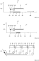
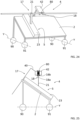
- a power station 1 with solar panels 2 is shown.
- the solar panels 2 may be thermal panels, i.e. panels comprising thermal solar collectors for transforming part of the solar radiation into heat.
- the solar panels 2 are photovoltaic panels, also called photovoltaic modules, i.e. they comprise photovoltaic cells for converting part of the solar radiation into electrical energy.
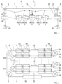
- the power station 1 comprises several solar panels 2.
- the solar panels 2 are distributed over several rows 3a to 3d. On the figure 2 , at least four rows 3a to 3d have been shown as an example.
- Each row 3a to 3d may comprise several solar panels 2, preferably aligned.
- each row 3a to 3d comprises at least four solar panels 2.
- a solar panel 2 has the general shape of a parallelepiped. Furthermore, each solar panel 2 comprises at least one support 90, 91 configured to support the solar panel 2.
- the supports 90, 91 may be anchored or placed on the ground, and in this case the power plant 1 is said to be “terrestrial”.
- the supports 90, 91 are floats intended to be placed on water, and in this case the power plant 1 is said to be “floating”. It is also said that the supports 90, 91 are floating.
- the power plant 1 comprises a cleaning system 4 configured to clean the solar panels 2.
- the cleaning system 4 comprises at least one cleaning device 5 capable of cleaning at least one solar panel 2.
- the cleaning system 4 comprises a transport apparatus 6 configured to transport the cleaning devices 5 by towing cable 7.
- a single cleaning device 5 has been shown for the purposes of simplification.
- the transport apparatus 6 makes it possible to tow the cleaning devices 5 and facilitates the transfer of the cleaning devices 5 from one solar panel 2 to another.
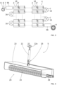
- the transport apparatus 6 comprises the towing cable 7, a drive pulley 8, at least one return pulley 9, a motor 10 and a tensioning device 11 for the towing cable 7.
- the drive pulley 8 is configured to drive the towing cable 7 when it is rotated about an axis of rotation A.
- the motor 10 is coupled to the drive pulley 8 and allows it to rotate about the axis of rotation A.
- the return pulley 9 allows, using the tensioning device 11, to tension the towing cable 7 to facilitate the movement of the towing cable 7.
- the tensioning device 11 comprises a support element 12 and a hydraulic cylinder 13 which connects the support element 12 to an axis of rotation B of the return pulley 9.
- the hydraulic cylinder 13 can adapt the tension that it exerts on the axis of rotation B, and therefore allows the tension of the towing cable 7 to be varied.
- the towing cable 7 can be made of steel, for example from strands gathered in the shape of a helix.
- the towing cable 7 can also be made of nylon, with one strand or several strands gathered in the shape of a helix and forming strands. Alternatively, the towing cable 7 may be wrapped in a plastic sheath.
- the motor 10 is mounted on a motor frame 14 and the rotation axis B of the return pulley 9 is mounted on a support frame 15.
- the cleaning system 4 comprises a return pulley 9 and a drive pulley 8.
- the motor 10 can rotate the drive pulley 8 in a single direction of rotation.
- the cleaning devices 5 travel the loop formed by the towing cable 7 always in the same direction.
- the motor 10 can reverse the direction of rotation of the drive pulley 8, and the cleaning devices 5 can travel the loop in one direction and the other.
- the transport apparatus 6 is said to operate back and forth.
- the cleaning system 4 comprises one or more deflection pulleys 16 for deflecting the path of the towing cable 7.
- the deflection pulleys 16 make it possible to clean several rows of solar panels 2.
- Each deflection pulley 16 is also mounted in rotation about an axis of rotation C.
- the axes of rotation C of the deflection pulleys 16 are respectively mounted on support frames not shown for the sake of simplification.
- the motor 14 and support 15 frames are anchoring elements fixed to the ground.
- the motor 14 and support 15 frames of the deflection 16 and return 9 pulleys are floats placed on the water and equipped with anchoring systems 92 for holding the frames 14, 15 in position.
- the supports 90, 91 of the solar panels 2 can also be equipped with an anchoring system 92.
- each row 3a, 3d comprises several panels solar panels 2.
- the solar panels 2 of a row 3a to 3d are aligned, that is to say they are arranged next to each other successively along a direction D, E, called the alignment direction.
- the solar panels 2 of a first row 3a are aligned in the first direction D.
- the solar panels 2 of a second row 3b are aligned in the second direction E.
- the rows 3a to 3d are arranged in parallel, in other words the rows 3a to 3d are said to be parallel to each other.
- the alignment directions D, E of the solar panels 2 are parallel. All of the solar panels 2 form a series.
- the series comprises the solar panels 2 of the different rows 3a to 3d.
- the transport apparatus 6 is configured such that the towing cable 7 is arranged along the different rows 3a to 3d of solar panels 2.
- the cleaning system 4 may comprise several deflection pulleys 16.
- a deflection pulley 16 is located at the end of a row 3a to 3d.
- a deflection pulley 16 is located at the end of two successive rows 3a to 3d. Each time a deflection pulley 16 passes, the towing cable 7 changes direction.
- a deflection pulley 16 therefore allows the towing cable 7 to pass from one row 3a to 3d to the other.
- the towing cable 7 is positioned so that it connects the drive pulley 8 to the return pulley 9 by passing in contact with each deflection pulley 16.
- the drive 8, return 9 and deflection 16 pulleys are configured so as to position the towing cable 7 so that it passes at the level of, i.e. above, each solar panel 2.
- the towing cable 7 extends along the different rows 3a to 3d, i.e. along the different alignment directions D, E. The position of the towing cable 7 allows a change of rows 3a, 3d for the cleaning device 5.
- the towing cable 7 when the towing cable 7 is animated in movement, it allows a cleaning device 5 to be towed from one solar panel 2 to the other, and more particularly from one row 3a to 3d to the other. for cleaning several rows 3a to 3d of solar panels 2.
- several rows 3a to 3d is meant the fact that several solar panels 2 belonging respectively to several rows 3a to 3d, are arranged next to each other in a direction perpendicular to the alignment directions D, E.
- the deflection pulleys 16 allow a change of direction D, E of the traction cable 7 to allow the cleaning device 5 to change rows 3a to 3d.
- the deflection pulleys 16 make it possible to clean a series of solar panels of different rows 3a to 3d, preferably parallel. Thus, it is possible clean multiple rows 3a to 3d of solar panels 2.
- Such a transport apparatus 6 makes it possible to use a remote motor 10 to drive the cleaning devices 5. That is to say, the motor 10 is located at a distance from the cleaning devices 5. Furthermore, thanks to the transport apparatus 6, a single motor 10 is used to move the cleaning devices 5. Maintenance of the cleaning system 4 is therefore simpler. Furthermore, the cleaning devices 5 are not necessarily equipped with wheels, drive motors, or electronic equipment to control their positioning and to control obstacles. The cleaning devices 5 can therefore be lighter and simpler to produce.
- the towing cable 7 forms a continuous loop and passes around the drive pulleys 8, return pulleys 9 and deflection pulleys 16.
- the towing cable 7 is in contact with each of the pulleys 8, 9, 16.
- five deflection pulleys 16 are shown as an example.
- the drive pulley 8 When the drive pulley 8 is rotated, it drives the towing cable 7 in translation in a first direction, represented by the reference D, in particular from the drive pulley 8 to a first deflection pulley 16.
- the towing cable 7 is driven in translation in a second direction E opposite to the first direction D, in particular between the first deflection pulley 16 and a second deflection pulley.
- the cleaning system 4 may also comprise at least one platform 95, 96 as a starting and/or arrival point for the cleaning devices 5.
- platform 95 corresponds to the starting and arrival point of devices 5.
- the unit 1 is shown, in which the traction cable 7 is wound around the drive pulley 8.
- the traction cable 7 does not form a continuous loop but a single strand which is wound and unwound, using the drive pulley 8, to change the direction of the first and second directions D, E.
- the motor 10 can reverse the direction of rotation of the drive pulley 8, and the transport apparatus 6 operates back and forth.
- the cleaning system 4 can comprise a departure dock 95 for the devices and an arrival dock 96 for the devices 5.
- the towing cable 7 is an aerial cable, that is to say that the towing cable 7 is held in the air.
- the cleaning system 4 may comprise one or more jibs 17.
- a jib 17 is a support element for the towing cable 7.
- a jib 17 carries one or more rotating elements 18, 80.
- a rotating element 18, 80 is an element rotatably mounted on the jib 17, configured to support and guide the towing cable 7.
- the rotating elements 18, 80 are rotating rollers, i.e. cylinders with a circular section and provided with a groove to facilitate the guiding of the towing cable 7.
- each solar panel 2 is equipped with a bracket 17.
- a bracket 17 may be mounted on an edge of a solar panel 2. More particularly, each bracket 17 is mounted at one end of a solar panel 2.
- the cleaning device 5 comprises a cleaning element 20, a pole 21 connected to the cleaning element 20 and a fixing means 22 connected to the pole 21.
- the different parts 20, 21 and 22 of the cleaning device 5 are mechanically connected to each other.
- the pole 21 is an elongated element, for example a cylindrical element, preferably a rod.
- the pole 21 may comprise a threaded rod and a tapped tube intended to cooperate with the threaded rod.
- the pole 21 may have a constant length adjustable as a function of a distance between the towing cable 7 and the solar panel 2.
- the pole 21 may also be telescopic or comprise a winder.
- the pole 21 may have a variable length to adapt to differences in distance between the towing cable 7 and the solar panels 2.
- the pole 21 may further comprise a damping system, for example a hydraulic or pneumatic cylinder to avoid damaging the solar panels 2 when the cleaning devices 5 are in contact with the solar panels 2.
- the fastening means 22 is configured to attach the pole 21 to the towing cable 7.
- the fastening means 22 is preferably located at one end of the pole 21.
- the fastening means 22 comprises a fastening clamp 22a.
- the fastening clamp 22a is configured to pass at the level of the drive pulleys 8, return pulleys 9 and deflection pulleys 16.
- the cleaning device(s) 5 attached to the towing cable 7 are driven.
- the movement of the cleaning device(s) 5 makes it possible to clean the surface of the solar panels 2.
- the cleaning element 20 may be movable.
- the cleaning element 20 comprises a frame 23 on which is mounted a rotating brush 24, advantageously several rotating brushes.
- the rotating brush 24 can be made with synthetic fibers or animal hair.
- the pole 21 can be mounted on the frame 23 by means of a joint 25.
- the cleaning device 5 can comprise a drive unit 29, for example an electric motor, configured to drive the rotating brush 24 in operation in order to improve cleaning.
- the cleaning device 5 comprises a scraper 26 mounted on the chassis 23.
- the scraper 26 can be a plate made of rubber, silicone, or flexible plastic.
- the cleaning element 20 may further be motorized, as illustrated in the figures 5 , 7 and 8 .
- the cleaning device 5 comprises a drive unit 29, for example an electric motor, configured to drive the cleaning element 20 into operation.
- the cleaning element 20 comprises one or more rotating pucks 27.
- the rotating puck(s) 27 are driven by one or more toothed wheels 28.
- the rotating pucks 27 can be oriented parallel to the chassis 23.
- the drive unit 29 drives the toothed wheels 28 in rotation, and therefore the rotating pucks 27.
- the cleaning device 5 comprises one or more nozzles 30 connected to one or more containers 31, and controlled by the drive unit 29.
- the containers 31 may comprise a liquid or a gas.
- the nozzles 30 are configured to produce a jet of liquid or gas contained in the container(s) 31.
- the cleaning element 20 comprises one or more vacuum cleaners 32 operated by the drive unit 29 to suck up the dirt.
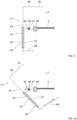
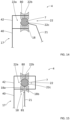
- a retractable bracket 17 which can occupy different positions S, T, V relative to the solar panel 2 on which it is mounted.
- a bracket 17 makes it possible to limit the parasitic shadows projected on the solar panels 2.
- the bracket 17 can occupy a deployed position S, called functional, in which it ensures the support and the guidance of the traction cable 7, and a retracted position V, called rest, in which the bracket 17 is placed partly under the solar panel 2.
- the boom 17 can occupy one or more intermediate positions T.
- the boom 17 In the deployed position S, the boom 17 can generate a shadow on the solar panel 2, and limit the energy yield of the latter.
- the boom 17 In the retracted position V, the boom 17 is placed partly under the solar panel 2 so as to no longer generate a shadow.
- the bracket 17 comprises an upper part 40 and a lower part 41.
- the upper part 40 comprises a first end 42 where the rotating rollers 18, 80 are mounted and a second opposite end 43 connected to the lower part 41.
- the solar panel 2 comprises an edge 44 on which the bracket 17 is connected.
- the bracket 17 comprises a piston 45, a pivot axis 46, a connecting element 47 and an actuator connection 48.
- the lower part 41 is integrated in the piston 45.
- the piston 45 is connected to the pivot axis 46.
- the pivot axis 46 is housed within the connecting element 47.
- the actuator connection 48 connects the lower part 41 to an actuator 49.
- the connecting element 47 is for example a stirrup, it is connected to the edge 44 of the solar panel 2, for example by a screw or by means of a clamp or a clamp.
- the connecting element 47 is partly open to allow a pivoting of the pivot axis 46 relative to an axis parallel to the edge 44.
- the bracket 17 comprises a torsion spring 50 mounted on the pivot axis 46. One of the ends of the spring 50 is fixed on the pivot axis 46 and another end is fixed on the connecting element 47 so as to constrain the bracket 17 in the deployed position S.
- the piston 45 comprises a cylinder 51 and an elastic system 52, for example a helical spring or a gas.
- the actuator connection 48 can be a flexible element, for example a cable, or a rigid one, such as a bar.
- the actuator 49 exerts a tension on the connecting element 48, the boom 17 pivots about the pivot axis 46 while bearing on the connecting element 47 and the boom 17 passes from the deployed position S to an intermediate position T, illustrated in FIG. figure 10 .
- the tension exerted on the actuator link 48 causes the boom 17 to tilt around the pivot axis 46.
- the boom 17 occupies its retracted position V, and the tension on the actuator connection 48 causes a compression of the piston 45, that is to say a sliding of the lower part 41 within the cylinder 51. The sliding causes a translation of the lower 41 and upper 40 parts of the boom 17 along the solar panel 2.
- the boom 17 occupies its retracted position V and the piston 45 is compressed.
- the actuator 49 releases the tension on the actuator connection 48, and the piston 45 decompresses.
- the piston 45 decompresses, the lower part 41 of the stem 17 slides, under the effect of the elastic system 52, towards the outside of the piston 45. Then, due to the spring 50, the stem 17 returns to its deployed position S.
- the actuator 49 is connected to several brackets 17 via several respective actuator links 48.
- the tension exerted on the towing cable 7 is also reduced.
- the tension is reduced using the tensioning device 11 which can vary the tension exerted on the towing cable 7.
- the jibs 17 can be retracted while maintaining the towing cable 7 in contact with the drive pulley 8, return pulley 9 and deflection pulley 16.
- the tension exerted on the towing cable 7 is increased using the tensioning device 11.
- the cleaning system 4 comprises means for supplying electrical energy to the electric drive unit 29 so as to be able to power it.
- the supply means may be an electrical energy storage unit, for example a battery, preferably a lithium-type battery.
- each cleaning device 5 comprises an electrical energy storage unit, not shown for the sake of simplification, mounted on the chassis 23 of the device 5.
- the supply means are an electrical energy generator 60 coupled to the electric drive unit 29 by means of electrical wires 61, 62 located along the towing cable 7.
- the generator 60 can be located on the engine chassis 14, in order to further supply the engine 10 of the transport apparatus 6.
- the generator 60 can correspond to the public network located remotely and connected, by electrical cables not shown for the sake of simplification, to the electrical wires 61, 62, and to the engine 10.
- the drive units 29 of the cleaning devices 5 are, for example, motors operating with single-phase 12 Volts DC. This voltage level is lower than 25 Volts AC which is considered to be a danger threshold for humans in a humid environment.
- the towing cable 7 supports the electric wires 61, 62 and the transport device 6 comprises connection means 63, 64 for connecting the generator 60 to the electrical wires 61, 62 respectively.
- a first connection means 63 comprises a first connector 65 in contact with a first electrical wire 62.
- the first connector 65 is connected to a first terminal 66 of the generator 60 via a first damping tensioner 67.
- the second connection means 64 comprises a second connector 68 in contact with the second electrical wire 61.
- the second connector 68 is connected to a second terminal 69 of the generator 60 via a second damping tensioner 70.
- the first and second connectors 65, 68 may be pads that rub on the electrical wires 61, 62.
- the first and second damping tensioners 67, 70 may be pneumatic cylinders, or a compression spring. The first and second damping tensioners 67, 70 maintain contact between the connectors 65, 68 and the electrical wires 61, 62, when the towing cable 7 swings up and down, for example in the event of wind.
- a cleaning device 5 is also shown comprising an electric drive unit 29 connected to the electric wires 61, 62 by respective connection wires 71, 72.
- the connection wires 71, 72 extend along the pole 21 of the cleaning device 5.
- the towing cable 7 is shown wrapped in an insulating part 73.
- the electrical wires 61, 62 are housed partly within the insulating part 73 so as to be insulated from each other and from the towing cable 7.
- the electrical wires 61, 62 are located along the towing cable 7.
- the electrical wires 61, 62 have a visible external part, i.e. not insulated, intended to be in contact with the connectors 65, 68 of the connection means 63, 64.
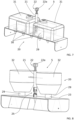
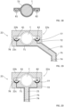
- the jib 17 comprises one or more rotating support rollers 18, located under the towing cable 7, intended to support and guide the towing cable 7.
- the jib 17 comprises rotating compression rollers 80, located on the towing cable 7, intended to press on the towing cable 7 to prevent it from coming out of the rotating support rollers 18 and leaving the jib 17.
- the pole 21 extends laterally with respect to the fixing means 22 so as to be able to pass next to the rotating support rollers 18 while allowing the fixing means 22 to pass over the rotating support rollers 18 when the cleaning device 5 passes at the jib 17.
- rotating compression rollers 80 can be placed on the jib 17.
- a rotating support roller 18 can be placed at the inlet of each pulley 8, 9, 16, i.e. at the level where the towing cable 7 comes into contact with the pulley 8, 9, 16, and also at the outlet of each pulley 8, 9, 16, i.e. at the level where the towing cable 7 comes out of the pulley 8, 9, 16 with which it is no longer in contact.
- the bracket 17 comprises one or more rotating support rollers 18, located under the towing cable 7, intended to support and guide the towing cable 7.
- the bracket 17 comprises rotating compression rollers 80, located on the towing cable 7, intended to press on the towing cable 7 to prevent it from coming out of the rotating support rollers 18 and leaving the bracket 17.
- each rotating support roller 18 comprises two half rotating rollers 18a, 18b placed opposite each other and spaced from each other by a gap 81 allowing passage of the pole 21 of the cleaning device 5.
- the gap 81 is further provided so that the towing cable 7 remains in contact with the half rotating rollers 18a, 18b after the passage of the pole 21.
- the pole 21 extends below the fixing means 22, in particular directly above the towing cable 7, so as to be able to pass between the rotating half-rollers 18a, 18b while allowing the fixing means 22 to pass over the rotating half-rollers 18a, 18b when the cleaning device 5 passes at the level of the jib 17.
- a bracket 17 adapted to the poles 21 extending below the fixing means 2 is shown.
- Such a bracket 17 also makes it possible to trap the towing cable 7 while avoiding losing the towing cable 7 during an operation of retracting the brackets 17.
- the fixing clamp 22a comprises two jaws 22b, 22c which are shaped to grip the towing cable 7.
- at least one jaw 22b, 22c is movable relative to the other.
- the upper jaw 22b is movable relative to the lower jaw 22c which is mechanically connected to the pole 21.
- the upper jaw 22b opens to place the fixing clamp 22a around the towing cable 7, then the upper jaw 22b by keeping it in contact with the lower jaw 22c, for example by means of a fixing bolt, that is to say a screw cooperating with a nut, to keep the fixing clamp 22a attached to the traction cable 7.
- the pole 21 extends laterally relative to the fixing clamp 22a.
- the pole 21 extends below the fixing clamp 22a.
- two embodiments of the pole 21 and the fixing clamp 22a adapted to a cleaning device 5 having a motorized cleaning element 20.
- the cleaning device 5 comprises two connection wires 71, 72 located along the pole 21.
- Each connection wire 71, 72 is surrounded by an insulating sheath to insulate the wires from each other and from the pole 21.
- connection wire 71, 72 comprises a first end 74, 75 connected to a terminal of the drive unit 29 of the cleaning device 5, and a second end 76, 77 shaped to be placed in contact with the respective electrical wires 61, 62 of the transport apparatus 6.
- each second end 76, 77 can be a conductive plate to promote electrical contact with the electrical wires 61, 62.
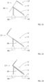
- FIG. 21 to 22 another embodiment of a power station 1 with solar panels 2 is shown.
- the solar panels 2 are inclined relative to a line Y passing through the supports 90, 91 of the solar panels 2.
- the solar panels 2 form a non-zero angle of less than 90° with the line Y passing through the supports 90, 91.
- FIGS. 21 to 22 The different positions of a retractable 17 gallows are also shown.
- the gallows 17 occupies a deployed position S.
- the stem 17 occupies a retracted position V in which the piston 45 is decompressed.
- the stem 17 occupies a retracted position V in which the piston 45 is compressed.
- FIG. 24 and 25 another embodiment of a power station 1 with solar panels 2 has also been shown.
- the solar panels 2 are inclined relative to the lines Y passing through their respective supports 90, 91.
- the cleaning device 5 comprises a pole 21 inclined relative to its frame 23.
- the inclination of the pole 21 is equal to the inclination of the solar panels 2.
- a jib 17 has also been shown having two rotating half-rollers 18a, 18b placed opposite each other and spaced from each other by a gap 81 allowing passage of the pole 21 of the cleaning device 5.
- the pole 21 extends below the fixing clamp 22a.
- a cleaning method for a power plant 1 with solar panels 2 can be implemented by the cleaning system 4 which has just been described.
Landscapes
- Engineering & Computer Science (AREA)
- Physics & Mathematics (AREA)
- Life Sciences & Earth Sciences (AREA)
- Sustainable Development (AREA)
- Sustainable Energy (AREA)
- Thermal Sciences (AREA)
- Chemical & Material Sciences (AREA)
- Combustion & Propulsion (AREA)
- Mechanical Engineering (AREA)
- General Engineering & Computer Science (AREA)
- Cleaning In General (AREA)
- Cleaning By Liquid Or Steam (AREA)
Claims (11)
- Reinigungssystem für Kraftwerk mit Solarpanels (2), das mindestens eine Reinigungsvorrichtung (5) mindestens eines Solarpanels (2), ein Transportgerät (6) der mindestens einen Reinigungsvorrichtung (5) durch Zugkabel (7) umfasst, wobei das Transportgerät (6) eine Antriebsscheibe (8) des Zugkabels (7) umfasst, dadurch gekennzeichnet, dass das Transportgerät (6) eine Umlenkscheibe (9) des Zugkabels (7) umfasst, wobei das Zugkabel (7) kontinuierlich um die Antriebsscheibe (8) und die Umlenkscheibe (9) angetrieben ist, und dass das Transportgerät (6) außerdem eine Ablenkscheibe (16) des Zugkabels (7) umfasst, und die mindestens eine Reinigungsvorrichtung (5) mit dem Zugkabel (7) durch eine Befestigungszange (22a) verbunden ist, die dazu konfiguriert ist, im Bereich der Antriebs- (8), Ablenk- (16) und Umlenkscheibe (9) durchzugehen.
- System nach Anspruch 1, das einen Ausleger (17) umfasst, der ein Drehelement (18, 18a, 18b) zum Tragen und Führen des Zugkabels (7) umfasst.
- System nach Anspruch 2, wobei der Ausleger (17) einziehbar ist.
- System nach einem der Ansprüche 1 bis 3, wobei die mindestens eine Reinigungsvorrichtung (5) ein motorisierte Reinigungselement (20) und eine Antriebseinheit (29) umfasst, die dazu konfiguriert ist, das motorisierte Reinigungselement (20) im Betrieb anzutreiben.
- System nach Anspruch 4, wobei die Antriebseinheit (29) elektrisch ist und die mindestens eine Reinigungsvorrichtung (5) eine Stromspeichereinheit umfasst, die mit der Antriebseinheit (29) gekoppelt ist.
- System nach Anspruch 4, wobei die Antriebseinheit (29) elektrisch ist und das Transportgerät (6) einen Stromgenerator (60) umfasst, der mit der Antriebseinheit (29) über Stromleiter (61, 62), die entlang des Zugkabels (7) liegen, gekoppelt ist.
- Kraftwerk mit Solarpanels (2), dadurch gekennzeichnet, dass es ein Reinigungssystem (4) nach einem der Ansprüche 1 bis 6 umfasst.
- Kraftwerk nach Anspruch 7, wobei jedes Solarpanel (2) einen schwimmenden Träger (90, 91) umfasst.
- Kraftwerk nach Anspruch 8, wobei jedes Solarpanel (2) ein Fotovoltaikpanel ist.
- Kraftwerk nach Anspruch 7, wobei jedes Solarpanel (2) einen am Boden verankerten Träger (90, 91) umfasst.
- Reinigungsverfahren für Kraftwerk mit Solarpanels (2), dadurch gekennzeichnet, dass es ein Ziehen mindestens einer Reinigungsvorrichtung (5) mindestens eines Solarpanels (2) durch ein Zugkabel (7) unter Verwendung eines Reinigungssystems nach einem der Ansprüche 1 bis 6 umfasst.
Applications Claiming Priority (2)
| Application Number | Priority Date | Filing Date | Title |
|---|---|---|---|
| FR2103865A FR3121851B1 (fr) | 2021-04-14 | 2021-04-14 | Système et procédé de nettoyage pour centrale à panneaux solaires |
| PCT/EP2022/059499 WO2022218870A1 (fr) | 2021-04-14 | 2022-04-08 | Système et procédé de nettoyage pour centrale à panneaux solaires |
Publications (3)
| Publication Number | Publication Date |
|---|---|
| EP4323701A1 EP4323701A1 (de) | 2024-02-21 |
| EP4323701B1 true EP4323701B1 (de) | 2025-01-15 |
| EP4323701C0 EP4323701C0 (de) | 2025-01-15 |
Family
ID=76523083
Family Applications (1)
| Application Number | Title | Priority Date | Filing Date |
|---|---|---|---|
| EP22722420.1A Active EP4323701B1 (de) | 2021-04-14 | 2022-04-08 | Reinigungssystem und -verfahren für ein solarkraftwerk |
Country Status (4)
| Country | Link |
|---|---|
| EP (1) | EP4323701B1 (de) |
| ES (1) | ES3022883T3 (de) |
| FR (1) | FR3121851B1 (de) |
| WO (1) | WO2022218870A1 (de) |
Families Citing this family (2)
| Publication number | Priority date | Publication date | Assignee | Title |
|---|---|---|---|---|
| CN118381453B (zh) * | 2024-05-23 | 2025-04-04 | 安徽常仪新能源有限公司 | 一种光伏发电装置 |
| CN119891926B (zh) * | 2024-12-25 | 2025-09-02 | 南通诚利钢结构工程有限公司 | 一种双玻光伏组件的自有钢结构固定装置 |
Family Cites Families (5)
| Publication number | Priority date | Publication date | Assignee | Title |
|---|---|---|---|---|
| ES2429216T3 (es) * | 2007-03-05 | 2013-11-13 | Novaton Erneuerbare Energien Ag | Sistema colector de energía solar |
| CN204231280U (zh) * | 2014-11-24 | 2015-03-25 | 韩国海 | 太阳能电池板自动清洁装置及其转运接驳机 |
| US9455665B1 (en) * | 2015-11-08 | 2016-09-27 | Ecoppia Scientific Ltd. | Solar tracker cleaning system and method |
| WO2019236382A1 (en) * | 2018-06-04 | 2019-12-12 | Edisun Microgrids, Inc. | Self-ballasted heliostat with suspended mirror assembly |
| KR102297166B1 (ko) * | 2019-08-19 | 2021-09-03 | 전남대학교산학협력단 | 태양광 패널 세척 및 관리용 병렬 케이블 로봇 시스템 |
-
2021
- 2021-04-14 FR FR2103865A patent/FR3121851B1/fr active Active
-
2022
- 2022-04-08 WO PCT/EP2022/059499 patent/WO2022218870A1/fr not_active Ceased
- 2022-04-08 EP EP22722420.1A patent/EP4323701B1/de active Active
- 2022-04-08 ES ES22722420T patent/ES3022883T3/es active Active
Also Published As
| Publication number | Publication date |
|---|---|
| FR3121851B1 (fr) | 2024-12-13 |
| WO2022218870A1 (fr) | 2022-10-20 |
| EP4323701C0 (de) | 2025-01-15 |
| ES3022883T3 (en) | 2025-05-29 |
| EP4323701A1 (de) | 2024-02-21 |
| FR3121851A1 (fr) | 2022-10-21 |
Similar Documents
| Publication | Publication Date | Title |
|---|---|---|
| EP4323701B1 (de) | Reinigungssystem und -verfahren für ein solarkraftwerk | |
| FR2663188A1 (fr) | Dispositif de ramassage de paillage sous forme de film plastique. | |
| EP3071012B1 (de) | Verfahren und vorrichtung zum ausfahren und einziehen einer plane zum sammeln von kleinen früchten und erntemaschinen | |
| EP2594128B1 (de) | Eingebaute Ausästungsvorrichtung | |
| FR2997875A1 (fr) | Dispositif permettant de nettoyer les surfaces reflechissantes de miroirs d'une installation solaire | |
| EP2361695B1 (de) | Vorrichtung zur Behandlung von Obst und Gemüse, mit einem hydraulisch gesteuerten Reinigungswagen sowie Reinigungsverfahren | |
| EP0023008B1 (de) | Bewegbare Maschine zum Waschen von Gemüsen | |
| FR2522245A1 (fr) | Materiel agricole pour la recolte de fruits et ensembles recepteurs constitutifs dudit materiel | |
| FR2773345A1 (fr) | Systeme de deroulage et de pose de fils tels que notamment de cables d'alimentation catenaires | |
| CA2733120C (fr) | Dispositif de traitement de produits tels que des fruits ou legumes a chariot de nettoyage et procede de nettoyage | |
| FR3121321A1 (fr) | Installation de protection de plantes en rang | |
| EP0842597A1 (de) | Überziehen von gepresstem Gut mit einer Schlauchfolie | |
| EP1505867A1 (de) | Greifvorrichtung zum führen und heben von spalierdrähten für spalierte pflanzen | |
| FR2864880A1 (fr) | Machine de recolte de produits genre poireaux notamment | |
| FR2560743A1 (fr) | Systeme d'arrosage continu par aspersion de surfaces cultivees | |
| FR3154890A1 (fr) | Système de production d’énergie photovoltaïque et procédé de pilotage d’un tel système | |
| EP1427628A1 (de) | Gemeinsam durch quer- und längswellenbewegung angetriebenes kriechfahrzeug | |
| FR2768415A1 (fr) | Dispositif de convoyage et d'elevation d'articles pour le chargement d'un vehicule | |
| WO2025262117A1 (fr) | Installation solaire comprenant un système de nettoyage, et procédé de nettoyage | |
| FR2995000A1 (fr) | Installation de fermeture ou de protection solaire, dispositif de contention et procede de mise en oeuvre d'un tel dispositif | |
| FR3140564A1 (fr) | Perche automatique télescopique et système de nettoyage comportant une telle perche | |
| FR3004310A1 (fr) | Appareil d'arrosage | |
| FR2678803A1 (fr) | Dispositif de collecte de champignons. | |
| FR2839612A1 (fr) | Dispositif de liaison des fils de palissage d'une vegetation palissee | |
| WO2024074689A1 (fr) | Perche automatique télescopique et système de nettoyage comportant une telle perche |
Legal Events
| Date | Code | Title | Description |
|---|---|---|---|
| STAA | Information on the status of an ep patent application or granted ep patent |
Free format text: STATUS: UNKNOWN |
|
| STAA | Information on the status of an ep patent application or granted ep patent |
Free format text: STATUS: THE INTERNATIONAL PUBLICATION HAS BEEN MADE |
|
| PUAI | Public reference made under article 153(3) epc to a published international application that has entered the european phase |
Free format text: ORIGINAL CODE: 0009012 |
|
| STAA | Information on the status of an ep patent application or granted ep patent |
Free format text: STATUS: REQUEST FOR EXAMINATION WAS MADE |
|
| 17P | Request for examination filed |
Effective date: 20231023 |
|
| AK | Designated contracting states |
Kind code of ref document: A1 Designated state(s): AL AT BE BG CH CY CZ DE DK EE ES FI FR GB GR HR HU IE IS IT LI LT LU LV MC MK MT NL NO PL PT RO RS SE SI SK SM TR |
|
| DAV | Request for validation of the european patent (deleted) | ||
| DAX | Request for extension of the european patent (deleted) | ||
| GRAP | Despatch of communication of intention to grant a patent |
Free format text: ORIGINAL CODE: EPIDOSNIGR1 |
|
| STAA | Information on the status of an ep patent application or granted ep patent |
Free format text: STATUS: GRANT OF PATENT IS INTENDED |
|
| RIC1 | Information provided on ipc code assigned before grant |
Ipc: H02S 40/10 20140101ALI20240722BHEP Ipc: F24S 20/70 20180101ALI20240722BHEP Ipc: F24S 40/20 20180101AFI20240722BHEP |
|
| INTG | Intention to grant announced |
Effective date: 20240820 |
|
| RAP3 | Party data changed (applicant data changed or rights of an application transferred) |
Owner name: COMMISSARIAT A L'ENERGIE ATOMIQUE ET AUX ENERGIESALTERNATIVES |
|
| GRAS | Grant fee paid |
Free format text: ORIGINAL CODE: EPIDOSNIGR3 |
|
| GRAA | (expected) grant |
Free format text: ORIGINAL CODE: 0009210 |
|
| STAA | Information on the status of an ep patent application or granted ep patent |
Free format text: STATUS: THE PATENT HAS BEEN GRANTED |
|
| AK | Designated contracting states |
Kind code of ref document: B1 Designated state(s): AL AT BE BG CH CY CZ DE DK EE ES FI FR GB GR HR HU IE IS IT LI LT LU LV MC MK MT NL NO PL PT RO RS SE SI SK SM TR |
|
| REG | Reference to a national code |
Ref country code: CH Ref legal event code: EP Ref country code: GB Ref legal event code: FG4D Free format text: NOT ENGLISH |
|
| REG | Reference to a national code |
Ref country code: DE Ref legal event code: R096 Ref document number: 602022009616 Country of ref document: DE |
|
| REG | Reference to a national code |
Ref country code: IE Ref legal event code: FG4D Free format text: LANGUAGE OF EP DOCUMENT: FRENCH |
|
| U01 | Request for unitary effect filed |
Effective date: 20250211 |
|
| U07 | Unitary effect registered |
Designated state(s): AT BE BG DE DK EE FI FR IT LT LU LV MT NL PT RO SE SI Effective date: 20250217 |
|
| REG | Reference to a national code |
Ref country code: ES Ref legal event code: FG2A Ref document number: 3022883 Country of ref document: ES Kind code of ref document: T3 Effective date: 20250529 |
|
| U20 | Renewal fee for the european patent with unitary effect paid |
Year of fee payment: 4 Effective date: 20250430 |
|
| PG25 | Lapsed in a contracting state [announced via postgrant information from national office to epo] |
Ref country code: RS Free format text: LAPSE BECAUSE OF FAILURE TO SUBMIT A TRANSLATION OF THE DESCRIPTION OR TO PAY THE FEE WITHIN THE PRESCRIBED TIME-LIMIT Effective date: 20250415 |
|
| PG25 | Lapsed in a contracting state [announced via postgrant information from national office to epo] |
Ref country code: PL Free format text: LAPSE BECAUSE OF FAILURE TO SUBMIT A TRANSLATION OF THE DESCRIPTION OR TO PAY THE FEE WITHIN THE PRESCRIBED TIME-LIMIT Effective date: 20250115 |
|
| PGFP | Annual fee paid to national office [announced via postgrant information from national office to epo] |
Ref country code: ES Payment date: 20250519 Year of fee payment: 4 |
|
| PG25 | Lapsed in a contracting state [announced via postgrant information from national office to epo] |
Ref country code: IS Free format text: LAPSE BECAUSE OF FAILURE TO SUBMIT A TRANSLATION OF THE DESCRIPTION OR TO PAY THE FEE WITHIN THE PRESCRIBED TIME-LIMIT Effective date: 20250515 Ref country code: NO Free format text: LAPSE BECAUSE OF FAILURE TO SUBMIT A TRANSLATION OF THE DESCRIPTION OR TO PAY THE FEE WITHIN THE PRESCRIBED TIME-LIMIT Effective date: 20250415 |
|
| PG25 | Lapsed in a contracting state [announced via postgrant information from national office to epo] |
Ref country code: HR Free format text: LAPSE BECAUSE OF FAILURE TO SUBMIT A TRANSLATION OF THE DESCRIPTION OR TO PAY THE FEE WITHIN THE PRESCRIBED TIME-LIMIT Effective date: 20250115 |
|
| PG25 | Lapsed in a contracting state [announced via postgrant information from national office to epo] |
Ref country code: GR Free format text: LAPSE BECAUSE OF FAILURE TO SUBMIT A TRANSLATION OF THE DESCRIPTION OR TO PAY THE FEE WITHIN THE PRESCRIBED TIME-LIMIT Effective date: 20250416 |
|
| PG25 | Lapsed in a contracting state [announced via postgrant information from national office to epo] |
Ref country code: SM Free format text: LAPSE BECAUSE OF FAILURE TO SUBMIT A TRANSLATION OF THE DESCRIPTION OR TO PAY THE FEE WITHIN THE PRESCRIBED TIME-LIMIT Effective date: 20250115 |
|
| PG25 | Lapsed in a contracting state [announced via postgrant information from national office to epo] |
Ref country code: CZ Free format text: LAPSE BECAUSE OF FAILURE TO SUBMIT A TRANSLATION OF THE DESCRIPTION OR TO PAY THE FEE WITHIN THE PRESCRIBED TIME-LIMIT Effective date: 20250115 |
|
| PG25 | Lapsed in a contracting state [announced via postgrant information from national office to epo] |
Ref country code: SK Free format text: LAPSE BECAUSE OF FAILURE TO SUBMIT A TRANSLATION OF THE DESCRIPTION OR TO PAY THE FEE WITHIN THE PRESCRIBED TIME-LIMIT Effective date: 20250115 |
|
| PLBE | No opposition filed within time limit |
Free format text: ORIGINAL CODE: 0009261 |
|
| STAA | Information on the status of an ep patent application or granted ep patent |
Free format text: STATUS: NO OPPOSITION FILED WITHIN TIME LIMIT |
|
| REG | Reference to a national code |
Ref country code: CH Ref legal event code: H13 Free format text: ST27 STATUS EVENT CODE: U-0-0-H10-H13 (AS PROVIDED BY THE NATIONAL OFFICE) Effective date: 20251125 |
|
| REG | Reference to a national code |
Ref country code: CH Ref legal event code: L10 Free format text: ST27 STATUS EVENT CODE: U-0-0-L10-L00 (AS PROVIDED BY THE NATIONAL OFFICE) Effective date: 20251126 |
|
| PG25 | Lapsed in a contracting state [announced via postgrant information from national office to epo] |
Ref country code: MC Free format text: LAPSE BECAUSE OF FAILURE TO SUBMIT A TRANSLATION OF THE DESCRIPTION OR TO PAY THE FEE WITHIN THE PRESCRIBED TIME-LIMIT Effective date: 20250115 |
|
| 26N | No opposition filed |
Effective date: 20251016 |