EP4321908A1 - Verfahren und vorrichtung zur luminanzsteuerung - Google Patents
Verfahren und vorrichtung zur luminanzsteuerung Download PDFInfo
- Publication number
- EP4321908A1 EP4321908A1 EP22804895.5A EP22804895A EP4321908A1 EP 4321908 A1 EP4321908 A1 EP 4321908A1 EP 22804895 A EP22804895 A EP 22804895A EP 4321908 A1 EP4321908 A1 EP 4321908A1
- Authority
- EP
- European Patent Office
- Prior art keywords
- display
- luminance
- polarization
- electronic apparatus
- polarized light
- Prior art date
- Legal status (The legal status is an assumption and is not a legal conclusion. Google has not performed a legal analysis and makes no representation as to the accuracy of the status listed.)
- Pending
Links
Images


Classifications
-
- G—PHYSICS
- G09—EDUCATION; CRYPTOGRAPHY; DISPLAY; ADVERTISING; SEALS
- G09G—ARRANGEMENTS OR CIRCUITS FOR CONTROL OF INDICATING DEVICES USING STATIC MEANS TO PRESENT VARIABLE INFORMATION
- G09G3/00—Control arrangements or circuits, of interest only in connection with visual indicators other than cathode-ray tubes
- G09G3/20—Control arrangements or circuits, of interest only in connection with visual indicators other than cathode-ray tubes for presentation of an assembly of a number of characters, e.g. a page, by composing the assembly by combination of individual elements arranged in a matrix no fixed position being assigned to or needed to be assigned to the individual characters or partial characters
-
- G—PHYSICS
- G09—EDUCATION; CRYPTOGRAPHY; DISPLAY; ADVERTISING; SEALS
- G09G—ARRANGEMENTS OR CIRCUITS FOR CONTROL OF INDICATING DEVICES USING STATIC MEANS TO PRESENT VARIABLE INFORMATION
- G09G2300/00—Aspects of the constitution of display devices
- G09G2300/02—Composition of display devices
- G09G2300/023—Display panel composed of stacked panels
-
- G—PHYSICS
- G09—EDUCATION; CRYPTOGRAPHY; DISPLAY; ADVERTISING; SEALS
- G09G—ARRANGEMENTS OR CIRCUITS FOR CONTROL OF INDICATING DEVICES USING STATIC MEANS TO PRESENT VARIABLE INFORMATION
- G09G2320/00—Control of display operating conditions
- G09G2320/02—Improving the quality of display appearance
- G09G2320/0233—Improving the luminance or brightness uniformity across the screen
-
- G—PHYSICS
- G09—EDUCATION; CRYPTOGRAPHY; DISPLAY; ADVERTISING; SEALS
- G09G—ARRANGEMENTS OR CIRCUITS FOR CONTROL OF INDICATING DEVICES USING STATIC MEANS TO PRESENT VARIABLE INFORMATION
- G09G2320/00—Control of display operating conditions
- G09G2320/06—Adjustment of display parameters
- G09G2320/0686—Adjustment of display parameters with two or more screen areas displaying information with different brightness or colours
-
- G—PHYSICS
- G09—EDUCATION; CRYPTOGRAPHY; DISPLAY; ADVERTISING; SEALS
- G09G—ARRANGEMENTS OR CIRCUITS FOR CONTROL OF INDICATING DEVICES USING STATIC MEANS TO PRESENT VARIABLE INFORMATION
- G09G2360/00—Aspects of the architecture of display systems
- G09G2360/14—Detecting light within display terminals, e.g. using a single or a plurality of photosensors
- G09G2360/145—Detecting light within display terminals, e.g. using a single or a plurality of photosensors the light originating from the display screen
Definitions
- the disclosure relates to a method of controlling a luminance and an electronic apparatus therefor.
- a luminance may decrease as light passes through a plurality of spatial light modulators (SLMs) and an optical device.
- SLMs spatial light modulators
- a luminance may not be uniform in the entire display.
- the disclosure provides a method of controlling a luminance and an electronic apparatus therefor.
- an electronic apparatus including a first display, a second display, a lens array between the first display and the second display, a first polarization modulation array between the first display and the lens array, a second polarization modulation array between the lens array and the second display, a memory configured to store at least one instruction, and at least one processor configured to execute the at least one instruction to identify a first area having a luminance lower than a reference luminance in the second display, identify, to control a first luminance of the first area in the second display to be the reference luminance, a first polarization angle variation corresponding to a first area in the first polarization modulation array and a second polarization angle variation corresponding to a first area in the second polarization modulation array, control the first polarization modulation array based on the first polarization angle variation, and control the second polarization modulation array based on the second polarization angle variation.
- the at least one processor may be further configured to identify a second luminance of a reference area in the second display, identify, to maximize the second luminance, a third polarization angle variation corresponding to a reference area in the first polarization modulation array and a fourth polarization angle variation corresponding to a reference area in the second polarization modulation array, control the first polarization modulation array based on the third polarization angle variation, and control the second polarization modulation array based on the fourth polarization angle variation.
- the reference luminance may be a maximum value of the second luminance.
- the at least one processor may be further configured to identify a difference value between a luminance of a reference area in the first display and the second luminance, and identify the third polarization angle variation and the fourth polarization angle variation to minimize the difference value.
- the third polarization angle variation and the fourth polarization angle variation may be equal to an angle of a fast axis or an angle of a slow axis of the lens array with respect to an X-axis, the X-axis being a horizontal axis.
- the electronic apparatus may further include a camera configured to identify the second luminance, wherein the at least one processor is further configured to identify the second luminance based on changing a viewing angle of the camera.
- the first area may include one or more subpixels.
- the at least one processor may be further configured to control a rotation angle of the lens array, and identify the first polarization angle variation and the second polarization angle variation based on the rotation angle of the lens array.
- a method performed by an electronic apparatus including identifying a first area having a luminance lower than a reference luminance in a second display, identifying, to control a first luminance of the first area in the second display to be the reference luminance, a first polarization angle variation corresponding to a first area in a first polarization modulation array and a second polarization angle variation corresponding to a first area in a second polarization modulation array, controlling the first polarization modulation array based on the first polarization angle variation, and controlling the second polarization modulation array based on the second polarization angle variation.
- the method may further include identifying a second luminance of a reference area in the second display, identifying, to maximize the second luminance, a third polarization angle variation corresponding to a reference area in the first polarization modulation array and a fourth polarization angle variation corresponding to a reference area in the second polarization modulation array, controlling the first polarization modulation array based on the third polarization angle variation, and controlling the second polarization modulation array based on the fourth polarization angle variation.
- the reference luminance is a maximum value of the second luminance.
- the identifying of the third polarization angle variation and the fourth polarization angle variation may include identifying a difference value between a luminance of a reference area in the first display and the second luminance, and identifying the third polarization angle variation and the fourth polarization angle variation to minimize the difference value.
- the third polarization angle variation and the fourth polarization angle variation may be equal to an angle of a fast axis or a slow axis of a lens array with respect to an X-axis, the X-axis being a horizontal axis.
- the identifying of the second luminance may include identifying the second luminance based on changing a viewing angle of a camera of the electronic apparatus to identify the second luminance.
- the first area may include one or more subpixels.
- the method may further include controlling a rotation angle of a lens array, wherein the identifying of the first polarization angle variation and the second polarization angle variation is based on the rotation angle of the lens array.
- Another aspect of the disclosure provides a computer-readable recording medium storing a program for implementing the method to be performed by an electronic apparatus.
- an electronic apparatus including a first display, a second display, a lens array between the first display and the second display, a memory configured to store at least one instruction, and at least one processor configured to execute the at least one instruction to identify a luminance of the second display, identify, to maximize the luminance, a first rotation angle corresponding to a polarizer included in the first display and a second rotation angle corresponding to a polarizer included in the second display, rotate the polarizer in the first display based on the first rotation angle, and rotate the polarizer in the second display based on the second rotation angle.
- the at least one processor may be further configured to rotate the lens array, and identify the first rotation angle and the second rotation angle based on a rotation angle of the lens array.
- a method performed by an electronic apparatus including identifying a luminance of a second display, identifying, to maximize the luminance, a first rotation angle corresponding to a polarizer included in a first display and a second rotation angle corresponding to a polarizer included in the second display, rotating the polarizer in the first display based on the first rotation angle, and rotating the polarizer in the second display based on the second rotation angle.
- the method may further include rotating a lens array, wherein the identifying of the first rotation angle and the second rotation angle is based on a rotation angle of the lens array.
- each block of process flowcharts and combinations of the flowcharts may be performed by computer program instructions.
- the computer program instructions may be installed in a processor of a general-purpose computer, special-purpose computer, or other programmable data processing equipment, so that means to perform functions described in blocks of each flowchart may be produced by instructions executed by the processor of the computer or the other programmable data processing equipment.
- the computer program instructions may be stored in a computer usable or readable memory oriented to a computer or other programmable data processing equipment to implement functions in a particular way.
- an article of manufacture, including an instruction means for performing the function described in a block (or blocks) of each flowchart may be produced by the instructions stored in the computer usable or readable memory.
- the functions of the blocks of each flowchart may be provided by the instructions performing a series of operations in the computer or the other programmable data processing equipment to produce a process executable by the computer to generate a computer programmable instructions to operate the computer or the other data processing equipment.
- each block may represent a module, segment, or part of code that includes at least one executable instruction for executing specified logical function(s).
- the functions described in the blocks may be performed in an order different from that described herein. For example, two blocks illustrated consecutively may be performed substantially simultaneously or performed in a reverse order according to functions corresponding thereto in some cases.
- a machine-readable storage medium may be provided in the form of a non-transitory storage medium.
- the term “non-transitory storage medium” should be understood to mean a tangible device and to not include a signal (e.g., electromagnetic waves) but is not intended to distinguish between a case in which data is semi-permanently stored in the storage medium and a case in which data is temporarily stored in the storage medium.
- the "non-transitory storage medium” may include a buffer in which data is temporarily stored.
- methods according to various embodiments of the disclosure may be provided by being included in a computer program product.
- the computer program product may be traded as a product between a seller and a purchaser.
- the computer program product may be distributed in the form of a storage medium (e.g., compact disc read only memory (CD-ROM)) that is readable by devices, may be distributed through an application store (e.g., Play Store TM) or directly between two user devices (e.g., smartphones), or may be distributed online (e.g., by downloading or uploading).
- a storage medium e.g., compact disc read only memory (CD-ROM)
- CD-ROM compact disc read only memory
- an application store e.g., Play Store TM
- two user devices e.g., smartphones
- At least part of the computer program product may be at least temporarily stored or temporarily generated in a storage medium readable by devices such as the manufacturer's server, a server of an application store, or a memory of a relay server.
- a subpixel of one pixel may be understood to mean a subpixel of any one of R, G and B components constituting the pixel or a subpixel of any one of Y, U and V components constituting the pixel.
- subpixels at certain positions in a plurality of images may be understood to mean subpixels of one of R, G, and B components or one of Y, U and V components of pixels at the same positions in the plurality of images.
- the above definitions are based on an assumption that an RGB format or a YUV format is employed in an embodiment of the disclosure, and a subpixel may be also understood to mean a subpixel of any color component when another color format is employed.
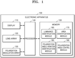
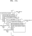
- FIG. 1 is a block diagram of an electronic apparatus 100 according to an embodiment of the disclosure.
- the electronic apparatus 100 may include a display 110, a lens array 120, a polarization modulation array 130, a processor 140, and a memory 150.
- components of the electronic apparatus 100 are not limited thereto, and the electronic apparatus 100 may further include other components or include some of the components.
- the display 110 may display various types of content such as text, images, moving pictures, icons, or symbols.
- the display 110 may include, but is not limited to, at least one of a liquid crystal display (LCD), a light-emitting diode (LED) display, an organic LED (OLED) display, a micro-LED display, a digital micromirror device (DMD), or a liquid- crystal-on-silicon (LCoS) display device.
- LCD liquid crystal display
- LED light-emitting diode
- OLED organic LED
- micro-LED organic LED
- DMD digital micromirror device
- LCD liquid- crystal-on-silicon
- the display 110 may include a plurality of displays.
- the display 110 may include a first display and a second display.
- the lens array 120 may include a field-of-view separator such as a lenticular lens to allow a user to view different images according to a viewing position.
- the lens array 120 may include a plurality of lenticular lenses having different pattern angles to realize a fine parallax.
- the electronic apparatus 100 may control an angle of polarization of polarized light incident on the polarization modulation array 130.
- the electronic apparatus 100 may control an angle of polarization by differently setting a variation in an angle of variation in each of areas in the polarization modulation array 130 on which polarized light is incident.
- the electronic apparatus 100 may change an angle of polarization of polarized light incident on a first area in the polarization modulation array 130 by a first polarization angle variation and an angle of polarization of polarized light incident on a second area in the polarization modulation array 130 by a second polarization angle variation.
- the polarization modulation array 130 may be a liquid crystal spatial light modulator (LCSLM). According to another embodiment, the polarization modulation array 130 may be manufactured by removing a color filter, two polarizers, and a black matrix from a liquid crystal display, but is not limited thereto.
- LCDMSLM liquid crystal spatial light modulator
- the polarization modulation array 130 may be manufactured by removing a color filter, two polarizers, and a black matrix from a liquid crystal display, but is not limited thereto.
- the processor 140 may execute at least one instruction stored in the memory 150 to control overall operations of the electronic apparatus 100.
- the processor 140 may identify (obtain) a first area in the second display having a luminance lower than a reference luminance.
- the processor 140 may identify the first polarization angle variation, which corresponds to a first area in the first polarization modulation array, and the second polarization angle variation, which corresponds to a first area in the second polarization modulation array, for controlling a first luminance of the first area to be the reference luminance.
- the processor 140 may control the first polarization modulation array, based on the first polarization angle variation.
- the processor 140 may control the second polarization modulation array, based on the second polarization angle variation.
- the memory 150 may include a luminance identification module 160, an area identification module 170, a polarization angle variation identification module 180, and a polarization angle control module 190.
- the luminance identification module 160 may store instructions for identifying a luminance of a reference area in the second display.
- the area identification module 170 may store instructions for identifying a first area in the second display having a luminance lower than the reference luminance.
- the polarization angle variation identification module 180 may store instructions for identifying the first polarization angle variation, which corresponds to the first area in the first polarization modulation array, and the second polarization angle variation, which corresponds to the first area in the second polarization modulation array, for controlling the first luminance of the first area to be the same as the reference luminance.
- the polarization angle control module 190 may store instructions for controlling the first polarization modulation array, based on the first polarization angle variation, and controlling the second polarization modulation array, based on the second polarization angle variation.
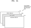
- FIGS. 2A and 2B illustrate examples of an electronic apparatus according to embodiments of the disclosure.
- FIG. 2A illustrates a configuration of an electronic apparatus 200 of the related art.
- the electronic apparatus 200 of the related art may include a first display 210, a second display 215, and a lens array 220.
- the lens array 220 may be positioned between the first display 210 and the second display 215.
- the lens array 220 may be formed of a material having a birefringence feature or may have the birefringence feature due to stress applied during a manufacturing process.
- the birefringence features of the lens array 220 may be changed due to stress applied during the manufacturing process. Accordingly, an angle of polarization of polarized light incident on the lens array 220 and a state of the polarized light may change when the polarized light passes through the lens array 220, and a luminance of the polarized light having passed through the lens array 220 may decrease when the polarized light passes through the second display 215.
- Areas in the lens array 220 may have different birefringence features due to stress applied during the manufacturing process.
- the different birefringence features of the areas may be understood to mean that the areas are different from one another in terms of a fast axis and a slow axis.
- a change of an angle and state of polarized light incident on each of the areas and a degree of reduction in a luminance of each of the areas may be different from those of the other areas due to the different birefringence features of the areas, as will be described with reference to FIGS. 3A to 3D below.
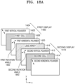
- FIG. 2B illustrates a configuration of an electronic apparatus 100 according to an embodiment of the disclosure.
- the electronic apparatus 100 may include a first display 260, a second display 265, a lens array 270, a first polarization modulation array 280, and a second polarization modulation array 285.
- the lens array 270 may be positioned between the first display 260 and the second display 265.
- the first polarization modulation array 280 may be positioned between the first display 260 and the lens array 270
- the second polarization modulation array 285 may be positioned between the lens array 270 and the second display 265.
- the first display 260 and the second display 265 may correspond to the display 110 of FIG. 1
- the lens array 270 may correspond to the lens array 120 of FIG. 1
- the first polarization modulation array 280 and the second polarization modulation array 285 may correspond to the polarization modulation array 130 of FIG. 1 .
- the electronic apparatus 100 may control the first polarization modulation array 280 and the second polarization modulation array 285 to control an angle of polarization of polarized light incident on the lens array 270.
- the electronic apparatus 100 may control a luminance of output light to be uniform by differently controlling a variation in an angle of polarization in areas in the first polarization modulation array 280 and the second polarization modulation array 285 on which polarized light is incident, as will be described with reference to FIGS. 4A to 4D below.
- An area in the lens array 270 may include one or more subpixels, but is not limited thereto.
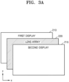
- FIGS. 3A to 3D illustrate an operation of an electronic apparatus 200 of the related art.
- FIG. 3A illustrates a configuration of an electronic apparatus 200 of the related art.
- the electronic apparatus 200 of the related art may include a first display 210, a second display 215, and a lens array 220.
- the lens array 220 may be positioned between the first display 210 and the second display 215.
- components of the electronic apparatus 200 of the related art are not limited thereto, and the electronic apparatus 200 may further include other components or include some of the components.
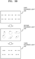
- FIG. 3B illustrates examples of polarized light having passed through each components of the electronic apparatus 200 of the related art.
- Pieces of first polarized light 330 are examples of a component having passed through the first display 210 among a plurality of components of light from backlight unit
- pieces of second polarized light 340 are examples of polarized light after the pieces of first polarized light 330 pass through the lens array 220
- pieces of polarized light 350 are examples a component having passed through the second display 215 among a plurality of components of the pieces of second polarized light 340.
- the pieces of first polarized light 330 may be pieces of linear polarized light having the same intensity and angle of polarization. For example, when all of pieces of light from the backlight are pieces of white light, only a component parallel to an orientation of a gap in a polarizer in the first display 210 among components of the pieces of white light may pass through the first display 210. Accordingly, the pieces of first polarized light 330 may be pieces of linear polarized light that have the same intensity and form an angle of 0° with respect to an X-axis.
- the pieces of second polarized light 340 may be linear polarized light, circular polarized light or elliptical polarized light.
- linear polarized light may change into linear polarized light, circular polarized light, or elliptical polarized light when passing through the lens array 220.
- areas in the lens array 220 may have different birefringence features due to stress applied during a manufacturing process and thus the pieces of second polarized light 340 may be pieces of linear, circular or elliptical polarized light having different intensities, shapes and/or directions of rotation.
- the pieces of third polarized light 350 may be pieces of linear polarized light having different intensities and the same angle of polarization.
- the pieces of second polarized light 340 are pieces of circular or elliptical polarized light having different intensities, shapes and directions of rotation, only a component parallel to the orientation of the gap in the polarizer in the second display 215 among the components of the pieces of second polarized light 340 may pass through the second display 215.
- the pieces of second polarized light 340 are different from one another in terms of a shape and direction of rotation, the amplitudes of components of the pieces of second polarized light 340 parallel to the orientation of the gap in the polarizer in the second display 215 are different from one another and thus the pieces of third polarized light 350 may be pieces of linear polarized light that have different intensities and form an angle of 0° with the X-axis.
- FIG. 3C illustrates examples of polarized light having passed through components of the electronic apparatus 200 of the related art.
- Pieces of first polarized light 360 are examples of a component having passed through the first display 210 among a plurality of components of light from a backlight unit
- pieces of second polarized light 350 are examples of polarized light after the pieces of first polarized light 360 pass through the lens array 220
- pieces of polarized light 380 are examples a component having passed through the second display 215 among a plurality of components of the pieces of second polarized light 370.
- the pieces of first polarized light 360 may be pieces of linear polarized light having the same intensity and angle of polarization. For example, when pieces of light from the backlight are pieces of white light corresponding to three pixels, only a component parallel to an orientation of a gap in a polarizer in the first display 210 among components of the pieces of white light may pass through the first display 210. Accordingly, the pieces of first polarized light 360 may be pieces of the first linear polarized light 362, the second linear polarized light 364, and the third linear polarized light 366 that have an amplitude of 255 and form an angle of 0° with respect to an X-axis.
- the pieces of second polarized light 370 may be linear polarized light, circular polarized light or elliptical polarized light.
- areas in the lens array 220 may have different birefringence features and the pieces of the first linear polarized light 362, the second linear polarized light 364, and the third linear polarized light 366 may change into pieces of circular polarized light having different intensities and shapes when passing through the areas in the lens array 220.
- the first linear polarized light 362 may change into first elliptical polarized light 372 having an amplitude of 250 in an X-axis direction and an amplitude of 20 in a Y-axis direction when passing through the lens array 220.
- the second linear polarized light 364 may change into second elliptical polarized light 374 having an amplitude of 200 in the X-axis direction and an amplitude of 158 in the Y-axis direction when passing through the lens array 220.
- the third linear polarized light 366 may change into third elliptical polarized light 376 having an amplitude of 210 in the X-axis direction and an amplitude of 144 in the Y-axis direction when passing through the lens array 220.
- the pieces of third polarized light 380 may be pieces of linear polarized light having different intensities and the same angle of polarization.
- the pieces of second polarized light 370 are pieces of circular or elliptical polarized light having different intensities, shapes and directions of rotation, only a component parallel to the orientation of the gap in the polarizer in the second display 215 among the components of the pieces of second polarized light 370 may pass through the second display 215.
- first linear polarized light 382 that have an amplitude of 250 in the X-axis direction and form an angle of 0° with the X-axis among components of the first elliptical polarized light 372 may pass through the second display 215.
- only second linear polarized light 384 that have an amplitude of 200 in the X-axis direction and form an angle of 0° with the X-axis among components of the second elliptical polarized light 374 may pass through the second display 215, and only third linear polarized light 386 that have an amplitude of 210 in the X-axis direction and form an angle of 0° with the X-axis among components of the third elliptical polarized light 376 may pass through the second display 215.
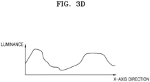
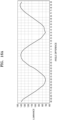
- FIG. 3D illustrates examples of a luminance of the electronic apparatus 200 of the related art on an X-axis.
- an amplitude of light having passed through the second display may decrease due to a birefringence feature of a lens array in the electronic apparatus 200 of the related art and thus the luminance of the electronic apparatus 200 may decrease.
- a luminance on the X-axis may vary according to a birefringence feature of the lens array in the electronic apparatus 200 of the related art.
- a luminance on the Y-axis may vary according to the birefringence feature of the lens array in the electronic apparatus 200 of the related art.
- FIGS. 4A to 4D illustrate an operation of an electronic apparatus 100 according to an embodiment of the disclosure.
- FIG. 4A illustrates a configuration of an electronic apparatus 100 according to an embodiment of the disclosure.
- the electronic apparatus 100 may include a first display 260, a second display 265, a lens array 270, a first polarization modulation array 280, and a second polarization modulation array 285.
- the lens array 270 may be positioned between the first display 260 and the second display 265.
- the first polarization modulation array 280 may be positioned between the first display 260 and the lens array 270
- the second polarization modulation array 285 may be positioned between the lens array 270 and the second display 265.
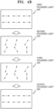
- FIG. 4B illustrates examples of polarized light having passed through components of the electronic apparatus 100.
- Pieces of first polarized light 440 are examples of a component having passed through the first display 260 among a plurality of components of light from a backlight
- pieces of second polarized light 445 are examples of polarized light after the pieces of first polarized light 440 pass through the first polarization modulation array 280.
- Pieces of third polarized light 450 are examples of polarized light after the pieces of second polarized light 445 pass through the lens array 270
- pieces of fourth polarized light 455 are examples of polarized light after the pieces of third polarized light 450 pass through the second polarization modulation array 285.
- the pieces of first polarized light 440 may be pieces of linear polarized light having the same intensity and angle of polarization. For example, when all of pieces of light from the backlight are pieces of white light, only a component parallel to an orientation of a gap in a polarizer in the first display 260 among components of the pieces of white light may pass through the first display 260. Accordingly, the pieces of first polarized light 440 may be pieces of linear polarized light that have the same intensity and form an angle of 0° with respect to an X-axis.
- the pieces of second polarized light 445 may be pieces of linear polarized light having the same intensity and different angles of polarization.
- the electronic apparatus 100 may change only an angle of polarization of polarized light incident on the first polarization modulation array 280 while maintaining the intensity of the polarized light.
- the electronic apparatus 100 may adjust the angle of polarization of the incident polarized light by differently changing a polarization angle variation of each area in the first polarization modulation array 280.
- the pieces of second polarized light 445 may be pieces of linear polarized light having different polarization angles according to an incident area.
- a polarization angle variation corresponding to each area in the first polarization modulation array 280 may be understood to mean a value for allowing a luminance of the electronic apparatus 100 to be equal to a reference luminance.
- the pieces of second polarized light 445 may be parallel to a fast axis or a slow axis in each area in the lens array as an angle of polarization of polarized light incident on each area in the first polarization modulation array 280 is adjusted based on a polarization angle variation.
- the pieces of third polarized light 450 may be pieces of linear polarized light having the same intensity and different angles of polarization. For example, when a first area in the lens array 270 has a quarter-wave plate feature, an intensity of and angle of polarization of polarized light having passed through the first area may be maintained. When a second area in the lens array 270 has a half-wave plate feature, an intensity of polarized light having passed through the second area may be maintained but an angle of polarization may change. Accordingly, the pieces of third polarized light 450 may have the same intensity as the pieces of second polarized light 445 and an angle of polarization that is the same as or different from the angle of polarization of the pieces of second polarized light 445.
- the pieces of fourth polarized light 455 may be pieces of linear polarized light having the same intensity and angle of polarization.
- the electronic apparatus 100 may change only an angle of polarization of polarized light incident on the second polarization modulation array 285 while maintaining the intensity of the polarized light.
- the electronic apparatus 100 may adjust the angle of polarization of the incident polarized light by differently changing a polarization angle variation of each area in the second polarization modulation array 285.
- the polarization angle variation corresponding to each area in the second polarization modulation array 285 may be understood to mean a value for allowing the pieces of fourth polarized light 455 to be parallel to an orientation of a gap in the polarizer in the second display 265.
- an angle of polarization of polarized light incident on each area in the second polarization modulation array 285 may be adjusted and thus the pieces of fourth polarized light 455 may have the same intensity and form an angle of 0° with the X-axis.
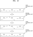
- FIG. 4C illustrates examples of polarized light having passed through components of the electronic apparatus 100.
- Pieces of first polarized light 460 are examples of a component having passed through the first display 260 among a plurality of components of light from a backlight unit
- pieces of second polarized light 465 are examples of polarized light after the pieces of first polarized light 440 pass through the first polarization modulation array 280.
- Pieces of third polarized light 470 are examples of polarized light after the pieces of second polarized light 465 pass through the lens array 270
- pieces of fourth polarized light 475 are examples of polarized light after the pieces of third polarized light 470 pass through the second polarization modulation array 285.
- the pieces of first polarized light 460 may be pieces of linear polarized light having the same intensity and angle of polarization. For example, when pieces of light from the backlight are pieces of white light corresponding to three pixels, only a component parallel to an orientation of a gap in a polarizer in the first display 260 among components of the pieces of white light may pass through the first display 260. Accordingly, the pieces of first polarized light 460 may be pieces of linear polarized light that have an amplitude of 255 and form an angle of 0° with the X-axis.
- the pieces of second polarized light 465 may be pieces of linear polarized light having the same intensity and different angles of polarization.
- the electronic apparatus 100 may adjust an angle of polarization of incident polarized light by differently setting a polarization angle variation for each area in the first polarization modulation array 280 and thus the pieces of second polarized light 465 may be pieces of linear polarized light that have an amplitude of 255 and form different angles with the X-axis.
- the pieces of third polarized light 470 may be pieces of linear polarized light having the same intensity and different angles of polarization.
- the pieces of third polarized light 470 may be pieces of linear polarized light having an amplitude of 255 and the same angle of polarization as the pieces of second polarized light 465.
- the pieces of fourth polarized light 475 may be pieces of linear polarized light having the same intensity and angle of polarization.
- the electronic apparatus 100 may adjust an angle of polarization of incident polarized light by differently setting a polarization angle variation for each area in the second polarization modulation array 285 and thus the pieces of fourth polarized light 475 may be pieces of linear polarized light that have an amplitude of 255 and form an angle of 0° with the X-axis.
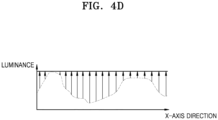
- FIG. 4D illustrates examples of a luminance of the electronic apparatus 100 on an X-axis.
- the electronic device 100 may adjust an angle of polarization of polarized light, based on a polarization angle variation for each area in the first polarization modulation array 280 and the second polarization modulation array 285, thereby maintaining an intensity of light passing through the electronic apparatus 100. Accordingly, the electronic apparatus 100 may have the same luminance regardless of an area.
- the electronic apparatus 100 may adjust an angle of polarization of polarized light incident on the first polarization modulation array 280 and the second polarization modulation array 285, so that a luminance on the Y-axis may be the same.
- FIGS. 5A to 5H are diagrams for describing a process of controlling a luminance by the electronic apparatus 100 according to an embodiment of the disclosure.
- the electronic apparatus 100 may set polarization angle variations of the first polarization modulation array 280 and the second polarization modulation array 285 to an initial value and identify a luminance of a reference area 510 in a second display.
- the electronic apparatus 100 may set polarization angle variations of the first polarization modulation array 280 and the second polarization modulation array 285 to the an initial value and identify a luminance of the reference area 510 when white light is generated from backlight.
- the initial value of the polarization angle variations may be set, based on previous data, but embodiments of the disclosure are not limited thereto.
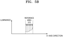
- FIG. 5B illustrates an example of a luminance of a reference area that reduces due to a birefringent feature of the lens array 270 in the electronic apparatus 100.
- the electronic apparatus 100 may identify a third polarization angle variation corresponding to a reference area in the first polarization modulation array 280 and a fourth polarization angle variation corresponding to a reference area in the second polarization modulation array 285 for maximizing the luminance of the reference area 510. Thereafter, the electronic apparatus 100 may control the first polarization modulation array 280, based on the third polarization angle variation, and control the second polarization modulation array 285 based on the fourth polarization angle variation, thereby maximizing the luminance of the reference area 510.
- the electronic apparatus 100 may appropriately adjust a polarization angle variation corresponding to reference areas in the first polarization modulation array 280 and the second polarization modulation array 285, so that the reference area 510 may uniformly have a maximum luminance on the X-axis as shown in FIG. 5B .
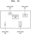
- the electronic apparatus 100 may identify an area having a luminance lower than a luminance of the reference area 510 or a reference luminance. For example, the electronic apparatus 100 may identify luminance of areas other than the reference area 510 when white light is generated from backlight unit and identify at least one area having a luminance lower than a reference luminance. Referring to FIG. 5C , the electronic apparatus 100 may identify four dark areas 520 to 550 having luminance lower than the reference luminance.
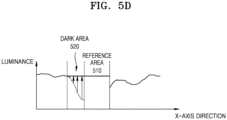
- FIG. 5D illustrates examples of identified luminance of all areas in the second display 265.
- luminance of the second display 265 may change along the X-axis as shown in FIG. 5D .
- the electronic apparatus 100 may identify a first polarization angle variation corresponding to a dark area in the first polarization modulation array 280 and a second polarization angle variation corresponding to a dark area in the second polarization modulation array 285 for controlling a luminance of a dark area in the electronic apparatus 100 to be the same as a reference luminance. Thereafter, the electronic apparatus 100 may control the first polarization modulation array 280, based on the first polarization angle variation, and control the second polarization modulation array 285 based on the second polarization angle variation, so that the luminance of the dark area may be the same as the reference luminance.
- the electronic apparatus 100 may appropriately adjust a polarization angle variation corresponding to the dark area 520 in the first polarization modulation array 280 and the second polarization modulation array 285, so that a luminance of the dark area 520 may be the same as a luminance of a reference area as shown in FIG. 5D .
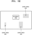
- FIG. 5E illustrates an example of a result of adjusting a polarization angle variation corresponding to a dark area in the first polarization modulation array 280 and the second polarized modulation array 285.
- a polarization angle variation corresponding to the dark area 520 in the first polarization modulation array 280 and the second polarization modulation array 285 may be appropriately adjusted so that the luminance of the dark area 520 may be the same as a luminance of a reference area, and thus, the dark area 520 may be unidentifiable.
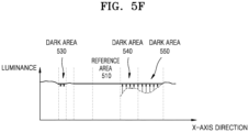
- FIG. 5F illustrates examples of identified luminance of all areas in the second display 265.
- the electronic apparatus 100 may identify a first polarization angle variation corresponding to a dark area in the first polarization modulation array 280 and a second polarization angle variation corresponding to a dark area in the second polarization modulation array 285, which are set to make a luminance of a dark area a reference luminance. Thereafter, the electronic apparatus 100 may control the first polarization modulation array 280, based on the first polarization angle variation, and control the second polarization modulation array 285 based on the second polarization angle variation, so that the luminance of the dark area may be equal to the reference luminance.
- the electronic apparatus 100 may appropriately adjust polarization angle variations corresponding to the dark areas 530 to 550 in the first polarization modulation array 280 and the second polarization modulation array 285, so that a luminance of the dark areas 530 to 550 may be the same as the luminance of the reference area as shown in FIG. 5F .
- FIG. 5G illustrates an example of a result of adjusting a polarization angle variation corresponding to an dark area in the first polarization modulation array 280 and the second polarized modulation array 285.
- a polarization angle variation corresponding to the dark areas 530 to 550 in the first polarization modulation array 280 and the second polarization modulation array 285 may be appropriately adjusted so that the luminance of each of the dark areas 530 to 550 may be the same as a luminance of a reference area, and thus, the dark areas 530 to 550 may be unidentifiable.
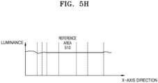
- FIG. 5H illustrates examples of identified luminance of all areas in the second display 270.
- a luminance of all areas in the second display 270 may be greater than or equal to a luminance of a reference area.
- a change in a luminance on the X-axis is shown in FIGS. 5B , 5D , 5F and 5H , a change in a luminance on the Y-axis may be substantially the same as the change in the luminance on the X-axis when the above-described operations are performed.
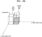
- FIGS. 6A to 6F are diagrams for describing a process of controlling a luminance by the electronic apparatus 100 according to an embodiment of the disclosure.
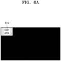
- the electronic apparatus 100 may set polarization angle variations of the first polarization modulation array 280 and the second polarization modulation array 285 to an initial value and identify a luminance of a first area 610 in the second display 270.
- the electronic apparatus 100 may set polarization angle variations of the first polarization modulation array 280 and the second polarization modulation array 285 to the initial value and identify a luminance of the first area 610 when white light is generated from backlight.
- the initial value of the polarization angle variation may be set, based on previous data, but embodiments of the disclosure are not limited thereto.
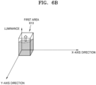
- the electronic apparatus 100 may identify a first polarization angle variation corresponding to the first area 610 in the first polarization modulation array 280 and a second polarization angle variation corresponding to the first area 610 in the second polarization modulation array 285 for maximizing a luminance of the first area 610. Thereafter, the electronic apparatus 100 may control the first polarization modulation array 280, based on the first polarization angle variation, and control the second polarization modulation array 285 based on the second polarization angle variation, thereby maximizing the luminance of the first area 610.
- the electronic apparatus 100 may set polarization angle variations of the first polarization modulation array 280 and the second polarization modulation array 285 to an initial value and identify a luminance of a second area 620 in the second display 270.
- the electronic apparatus 100 may set polarization angle variations of the first polarization modulation array 280 and the second polarization modulation array 285 to the initial value and identify a luminance of the second area 620 when white light is generated from backlight.
- the electronic apparatus 100 may identify a third polarization angle variation corresponding to the second area 620 in the first polarization modulation array 280 and a fourth polarization angle variation corresponding to the second area 620 in the second polarization modulation array 285 for maximizing a luminance of the second area 620. Thereafter, the electronic apparatus 100 may control the first polarization modulation array 280, based on the third polarization angle variation, and control the second polarization modulation array 285 based on the fourth polarization angle variation, thereby maximizing the luminance of the second area 620.
- the electronic apparatus 100 may appropriately adjust polarization angle variations corresponding to areas in the first polarization modulation array 280 and the second polarization modulation array 285, thereby maximizing luminance of all areas.
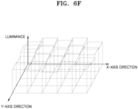
- all areas in the second display 270 may have a maximum luminance.
- FIG. 6F illustrates that all the areas in the second display 270 have different maximum luminance
- FIG. 6F provides only an example, and at least one of all of the areas in the second display 270 may have the same maximum luminance.
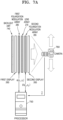
- FIGS. 7A and 7B are diagrams for describing a process of controlling a luminance by an electronic apparatus 100 according to an embodiment of the disclosure.
- the electronic apparatus 100 may include a first display 260, a second display 265, a lens array 270, a first polarization modulation array 280, a second polarization modulation array 285, and a backlight unit 740.
- the lens array 270 is positioned between the first display 260 and the second display 265, and the backlight unit 740 may be positioned before the first display 260.
- the first polarization modulation array 280 may be positioned between the first display 260 and the lens array 270, and the second polarization modulation array 285 may be positioned between the lens array 270 and the second display 265.
- the electronic apparatus 100 may include a processor 750 and a camera 760.
- the camera 760 may identify a luminance of the second display 265 according to a position of the camera 760, and the processor 750 may identify a polarization angle variation for maximizing the luminance of the second display 265 provided from the camera 760.
- the above description is intended to provide only an example and the electronic apparatus 100 may not include the camera 760.
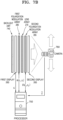
- the camera 760 may identify a luminance l ⁇ of a first area in the second display 265.
- the first area may include one or more adjacent pixels.
- the electronic apparatus 100 may identify a first polarization angle variation ⁇ (x 1 ,y 1) corresponding to a first area in the first polarization modulation array 280 and a second polarization angle variation ⁇ (x 2 ,y 2 ) corresponding to a first area in the second polarization modulation array 285 for maximizing the luminance l ⁇ , as expressed in Equations (1) to (3) below.
- p denotes an index of each of pixels included in a first area
- P denotes the total number of the pixels included in the first area
- l ⁇ (x p ,y p ) denotes a luminance of a pixel with an index p in the second display 265
- i ( x p ,y p ) denotes a luminance of a pixel with an index p in first display 260.
- F denotes a polarization modulation function of the first polarization modulation array 280
- Q denotes a polarization modulation function of the second polarization modulation array 285.
- ( x 1 , y 1 ) denotes a position of liquid crystal (LC) in the first polarization modulation array 280 corresponding to the first area
- ( x 2 , y 2 ) denotes a position of LC in the second polarization modulation array 285 corresponding to the first area
- the position of the LC in the first polarization modulation array 280 corresponding to the first area and the position of the LC in the second polarization modulation array 285 corresponding to the first area may be the same as the position of the first area in the second display 265, but are not limited thereto.
- the electronic apparatus 100 may identify a luminance of the second display 265 according to a viewing angle of the camera 760 while changing the viewing angle of the camera 769, and identify a polarization angle variation for maximizing the identified luminance.
- the electronic apparatus 100 may identify a luminance l ⁇ of the first area in the second display 265 and a luminance i of the first area in the first display 260, and identify the difference between l ⁇ and i .
- the first area may include one or more adjacent pixels.
- the electronic apparatus 100 may identify a first polarization angle variation ⁇ ( x 1, y 1 ) corresponding to the first area in the first polarization modulation array 280 and a second polarization angle variation ⁇ (x 2 ,y 2 ) corresponding to the first area in the second polarization modulation array 285 for minimizing the difference between l and i as expressed in Equations (4) to (6) below.
- p denotes an index of each of pixels included in a first area
- P denotes the total number of the pixels included in the first area l ⁇ (x p ,y p ) denotes a luminance of a pixel with an index p in the second display 265, and i ( x p ,y p ) denotes a luminance of a pixel with an index p in first display 260.
- F denotes a polarization modulation function of the first polarization modulation array 280
- Q denotes a polarization modulation function of the second polarization modulation array 285.
- a range of ⁇ ( x 1 , y 1 ) and ⁇ ( x 2 , y 2 ) is limited to 0 ⁇ 2 but is only intended to reduce load due to calculation and thus embodiments of the disclosure are not limited thereto.
- FIGS. 8A to 8G are diagrams for describing a process of controlling a luminance by an electronic apparatus 100 according to an embodiment of the disclosure.
- FIG. 8A illustrates a configuration of the electronic apparatus 100 according to an embodiment of the disclosure.
- the electronic apparatus 100 may include a first display 260, a second display 265, a lens array 270, a first polarization modulation array 280, and a second polarization modulation array 285.
- the lens array 270 may be positioned between the first display 260 and the second display 265.
- the first polarization modulation array 280 may be positioned between the first display 260 and the lens array 270
- the second polarization modulation array 285 may be positioned between the lens array 270 and the second display 265.
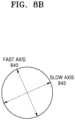
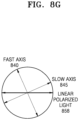
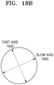
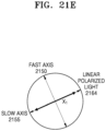
- FIG. 8B illustrates an example of a fast axis and a slow axis of a first area in the lens array 270.
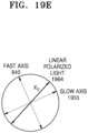
- the first area in the lens array 270 may have the quarter-wave plate feature, and a fast axis 840 and a slow axis 845 of the first area in the lens array 270 may be provided as illustrated in FIG. 8B .
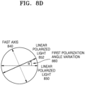
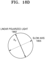
- FIG. 8C illustrates an example of linear polarized light having passed through the first display 260.
- linear polarized light 850 having passed through the first display 260 may have an intensity and an angle of polarization as shown in FIG. 8C .
- the linear polarized light 850 having passed through the first display 260 may change to linear polarized light 852 parallel to the slow axis 845 while passing through the first area in the first polarization modulation array 280.
- the electronic apparatus 100 may identify a first polarization angle variation 860, i.e., ⁇ , for maximizing a luminance of the second display 265 or controlling the luminance of the second display 265 to be the same as a reference luminance, and the linear polarized light 850 may rotate by the first polarization angle variation 860 to change to the linear polarized light 852 parallel to the slow axis 845 when passing through the first area in the first polarization modulation array 280.
- a first polarization angle variation 860 i.e., ⁇
- the linear polarized light 850 may rotate by the first polarization angle variation 860 to change to the linear polarized light 852 parallel to the slow axis 845 when passing through the first area in the first polarization modulation array 280.
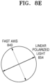
- an intensity and an angle of polarization of the linear polarized light 852 having passed through the first polarization modulation array 280 may be maintained when the linear polarized light 852 passes through the first area in the lens array 270.
- the linear polarized light 852 is parallel to the slow axis 845 of the first area in the lens array 270 and thus may change to linear polarized light 854 having the same intensity and angle of polarization as the linear polarized light 852 when passing through the area in the lens array 270.
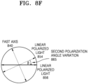
- the linear polarized light 854 having passed through the lens array 270 may change to linear polarized light 856 parallel to an orientation of a gap in a polarizer in the second display 265 while passing through the first area in the second polarization modulation array 285.
- the electronic apparatus 100 may identify a polarization angle variation 865, i.e., ⁇ , for maximizing the luminance of the second display 265 or controlling the luminance of the second display 265 to be the same as a reference luminance.
- the second polarization angle variation 865 and the first polarization angle variation 860 may be the same value with opposite direction, but embodiments of the disclosure are not limited thereto.
- the linear polarized light 854 may rotate by the second polarization angle variation 865 to change to the linear polarized light 856 parallel to the orientation of the gap in the polarizer in the second display 265, when passing through the first area in the second polarization modulation array 285.
- the linear polarized light 856 may be linear polarized light having the same intensity and angle of polarization as the linear polarized light 850.
- FIG. 8G illustrates an example of linear polarized light having passed through the second display 265.
- linear polarized light 858 having passed through the second display 265 may have the same intensity and angle of polarization as the linear polarized light 856.
- the linear polarized light 850 having passed through the first display 260 and the linear polarized light 858 having passed through the second display 265 may have the same intensity.
- the electronic apparatus 100 may identify the first polarization angle variation 860 corresponding to the first area in the first polarization modulation array 280 and the second polarization angle variation 865 corresponding to the first area in the second polarization modulation array 285 for maximizing the luminance of the second display 265 or controlling the luminance of the second display 265 to be the same as the reference luminance, and respectively control the first polarization modulation array 280 and the second polarization modulation array 285, based on the first polarization angle variation 860 and the second polarization angle variation 865. Accordingly, the linear polarized light 850 having passed through the first display 260 and the linear polarized light 858 having passed through the second display 265 may have the same intensity, thereby a reduction in the luminance of the second display 2
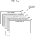
- FIGS. 9A to 9G are diagrams for describing a process of controlling a luminance by an electronic apparatus 100 according to an embodiment of the disclosure.
- FIG. 9A illustrates a configuration of the electronic apparatus 100 according to an embodiment of the disclosure.
- the electronic apparatus 100 may include a first display 260, a second display 265, a lens array 270, a first polarization modulation array 280, and a second polarization modulation array 285.
- the lens array 270 may be positioned between the first display 260 and the second display 265.
- the first polarization modulation array 280 may be positioned between the first display 260 and the lens array 270
- the second polarization modulation array 285 may be positioned between the lens array 270 and the second display 265.
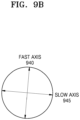
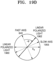
- FIG. 9B illustrates an example of a fast axis and a slow axis of a first area in the lens array 270.
- the first area in the lens array 270 may have the quarter-wave plate feature, and a fast axis 940 and a slow axis 945 in the first area in the lens array 270 may be formed as illustrated in FIG. 9B .
- FIG. 9C illustrates an example of linear polarized light having passed through the first display 260.
- linear polarized light 950 having passed through the first display 260 may have an intensity and an angle of polarization as shown in FIG. 9C .
- the linear polarized light 950 having passed through the first display 260 may change to linear polarized light 952 parallel to a fast axis 940 while passing through the first area in the first polarization modulation array 280.
- the electronic apparatus 100 may identify a fir9st polarization angle variation 960, e.g., ⁇ , for maximizing a luminance of the second display 265 or controlling the luminance of the second display 265 to be the same as a reference luminance, and the linear polarized light 950 may rotate by the first polarization angle variation 860 to change to the linear polarized light 952 parallel to the fast axis 940 when passing through the first area in the first polarization modulation array 280.
- a fir9st polarization angle variation 960 e.g., ⁇
- the linear polarized light 950 may rotate by the first polarization angle variation 860 to change to the linear polarized light 952 parallel to the fast axis 940 when passing through the first area in the first polarization modulation array 280.
- an intensity and an angle of polarization of the linear polarized light 952 having passed through the first polarization modulation array 280 may be maintained when the linear polarized light 952 passes through the first area in the lens array 270.
- the linear polarized light 952 is parallel to the fast axis 940 of the first area in the lens array 270 and thus may change to linear polarized light 954 having the same intensity and angle of polarization as the linear polarized light 952 when passing through the area in the lens array 270.
- the linear polarized light 954 having passed through the lens array 270 may change to linear polarized light 956 parallel to an orientation of a gap in a polarizer in the second display 265 while passing through the first area in the second polarization modulation array 285.
- the electronic apparatus 100 may identify a second polarization angle variation 965, i.e., ⁇ , for maximizing the luminance of the second display 265 or controlling the luminance of the second display 265 to be the same as a reference luminance.
- the second polarization angle variation 965 may be a value same with that of the first polarization angle variation 960 and a direction opposite to that of the first polarization angle variation 960 but is not limited thereto.
- the linear polarized light 954 may rotate by the second polarization angle variation 965 to change to the linear polarized light 956 parallel to the orientation of the gap in the polarizer in the second display 265, when passing through the first area in the second polarization modulation array 285.
- the linear polarized light 956 may be linear polarized light having the same intensity and angle of polarization as the linear polarized light 950.
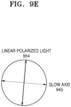
- FIG. 9G illustrates an example of linear polarized light having passed through the second display 265.
- linear polarized light 958 having passed through the second display 265 may have the same intensity and angle of polarization as the linear polarized light 956.
- the linear polarized light 950 having passed through the first display 260 and the linear polarized light 958 having passed through the second display 265 may have the same intensity.
- the electronic apparatus 100 may identify the first polarization angle variation 960 corresponding to the first area in the first polarization modulation array 280 and the second polarization angle variation 965 corresponding to the first area in the second polarization modulation array 285 for maximizing the luminance of the second display 265 or controlling the luminance of the second display 265 to be the same as the reference luminance, and respectively control the first polarization modulation array 280 and the second polarization modulation array 285, based on the first polarization angle variation 960 and the second polarization angle variation 965. Accordingly, the linear polarized light 950 having passed through the first display 260 and the linear polarized light 958 having passed through the second display 265 may have the same intensity, thereby a reduction in the luminance of the second display 2
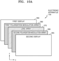
- FIGS. 10A to 10G are diagrams for describing a process of controlling a luminance by an electronic apparatus 100 according to an embodiment of the disclosure.
- FIG. 10A illustrates a configuration of the electronic apparatus 100 according to an embodiment of the disclosure.
- the electronic apparatus 100 may include a first display 260, a second display 265, a lens array 270, a first polarization modulation array 280, and a second polarization modulation array 285.
- the lens array 270 may be positioned between the first display 260 and the second display 265.
- the first polarization modulation array 280 may be positioned between the first display 260 and the lens array 270
- the second polarization modulation array 285 may be positioned between the lens array 270 and the second display 265.
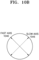
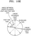
- FIG. 10B illustrates examples of a fast axis and a slow axis of the first area in the lens array 270.
- the first area in the lens array 270 may have the half-wave plate feature, and a fast axis 1040 and a slow axis 1045 in the first area in the lens array 270 may be formed as illustrated in FIG. 10B .
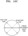
- FIG. 10C illustrates an example of linear polarized light having passed through the first display 260.
- linear polarized light 1050 having passed through the first display 260 may have an intensity and an angle of polarization as shown in FIG. 10C .
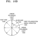
- the linear polarized light 1050 having passed through the first display 260 may change to linear polarized light 1052 that are not parallel to the fast axis 1040 and the slow axis 1045 when passing through the first area in the first polarization modulation array 280.
- the electronic apparatus 100 may identify a first polarization angle variation 1060, i.e.., ⁇ , for maximizing a luminance of the second display 265 or controlling the luminance of the second display 265 to be the same as a reference luminance, and the linear polarized light 1050 may rotate by the first polarization angle variation 1060 to change to the linear polarized light 1052 parallel to the fast axis 1040 when passing through the first area in the first polarization modulation array 280.
- the first polarization angle variation 1060 may be a certain value.
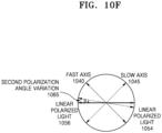
- an intensity of the linear polarized light 1052 having passed through the first polarization modulation array 280 may be maintained but an angle of polarization may change, when the linear polarized light 1052 passes through the first area in the lens array 270.
- the linear polarized light 1052 may rotate by twice an angle 1070, i.e., ⁇ , between the linear polarized light 1052 and the fast axis 1040 while passing through the first area in the lens array 270 and thus may change to linear polarized light 1054 having the same intensity as the linear polarized light 1052 and a different angle of polarization from that of the linear polarized light 1052.
- ⁇ an angle 1070
- the linear polarized light 1054 having passed through the lens array 270 may change to linear polarized light 1056 parallel to an orientation of a gap in a polarizer in the second display 265 while passing through the first area in the second polarization modulation array 285.
- the electronic apparatus 100 may identify a second polarization angle variation 1065, i.e., ⁇ , for maximizing the luminance of the second display 265 or controlling the luminance of the second display 265 to be the same as a reference luminance.
- the second polarization angle variation 1065 and the first polarization angle variation 1060 may be different values but embodiments of the disclosure are not limited thereto.
- the linear polarized light 1054 may rotate by the second polarization angle variation 1065 to change to the linear polarized light 1056 parallel to the orientation of the gap in the polarizer in the second display 265, when passing through the first area in the second polarization modulation array 285.
- the linear polarized light 1056 may be linear polarized light having the same intensity and angle of polarization as the linear polarized light 1050.
- FIG. 10G illustrates an example of linear polarized light having passed through the second display 265.
- linear polarized light 1058 having passed through the second display 265 may have the same intensity and angle of polarization as the linear polarized light 1056.
- the linear polarized light 1050 having passed through the first display 260 and the linear polarized light 1058 having passed through the second display 265 may have the same intensity.
- the electronic apparatus 100 may identify the first polarization angle variation 1060 corresponding to the first area in the first polarization modulation array 280 and the second polarization angle variation 1065 corresponding to the first area in the second polarization modulation array 285 for maximizing the luminance of the second display 265 or controlling the luminance of the second display 265 to be the same as the reference luminance, and respectively control the first polarization modulation array 280 and the second polarization modulation array 285, based on the first polarization angle variation 1060 and the second polarization angle variation 1065. Accordingly, the linear polarized light 1050 having passed through the first display 260 and the linear polarized light 1058 having passed through the second display 265 may have the same intensity, thereby a reduction in the luminance of the second display 2
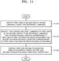
- FIG. 11 is a flowchart of a process of controlling a luminance by an electronic apparatus according to an embodiment of the disclosure.
- the electronic apparatus may identify a first area having a luminance lower than a reference luminance in a second display.
- the reference luminance may be a maximum luminance of a reference area in the second display.
- the electronic apparatus may identify the luminance of the reference area in the second display, and identify, for maximizing the luminance of the reference area, a third polarization angle variation corresponding to a reference area in a first polarization modulation array and a fourth polarization angle variation corresponding to a reference area in a second polarization modulation array.
- the electronic apparatus may respectively control the first and second polarization modulation arrays, based on the third and fourth polarization angle variations, so that the reference area may have a maximum luminance.
- the electronic apparatus may identify a difference value between a luminance of a reference area in a first display and the luminance in the reference area in the second display area, and identify the third polarization angle variation and the fourth polarization angle variation for minimizing the difference.
- the third polarization angle variation and the fourth polarization angle variation may be the same as an angle of a fast or slow axis of a lens array with respect to the X-axis.
- the electronic apparatus may include a camera for identifying the luminance of the reference area and identify the luminance of the reference area according to a viewing angle of the camera.
- the electronic apparatus may identify, for controlling a first luminance of the first area to be a reference luminance, a first polarization angle variation corresponding to a first area in the first polarization modulation array and a second polarization angle variation corresponding to a first area in the second polarization modulation array.
- the electronic apparatus may control a rotation angle of the lens array, and identify the first and second polarization angle variations, based on the rotation angle of the lens array.
- the electronic apparatus may respectively control the first and second polarization modulation arrays, based on the first and second polarization angle variations. Therefore, the luminance of the first area in the second display may be the same as the reference luminance.
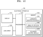
- FIG. 12 is a block diagram of an electronic apparatus 1200 according to an embodiment of the disclosure.
- the electronic apparatus 100 may include a display 1210, a lens array 1220, a polarization modulation array 1230, and a processor 1240.
- components of the electronic apparatus 1200 are not limited thereto, and the electronic apparatus 1200 may further include other components or include some of the components.
- the display 1210 may display various types of content such as text, images, moving pictures, icons, or symbols. According to an embodiment of the disclosure, the display 1210 may include, but is not limited to, at least one of an LCD, an LED display, an OLED display, a micro-LED display, a DMD, or an LCoS display device.
- the display 1210 may include a plurality of displays.
- the display 1210 may include a first display and a second display.
- each of the first display and the second display may include a vertical polarizer, a horizontal polarizer, and a cell.
- the lens array 1220 may include a field-of-view separator such as a lenticular lens to allow a user to view different images according to a viewing position.
- the lens array 1220 may include a plurality of lenticular lenses having different pattern angles to realize a fine parallax.
- the processor 1230 may execute at least one instruction stored in the memory 1240 to control overall operations of the electronic apparatus 1200.
- the processor 1230 may identify a luminance of the second display.
- the processor 1230 may identify a first rotation angle corresponding to the first display and a second rotation angle corresponding to the second display for maximizing the luminance of the second display.
- the processor 1230 may rotate a polarizer in the first display, based on the first rotation angle.
- the processor 1230 may rotate a polarizer in the second display, based on the second rotation angle.
- the memory 1240 may include a luminance identification module 1250, an angle-of-rotation identification module 1260, and a polarizer control module 1270.
- the luminance identification module 1250 may store instructions for identifying the luminance of the second display.
- the angle-of-rotation identification module 1260 may store instructions for identifying the first rotation angle corresponding to the first display and the second rotation angle corresponding to the second display for maximizing the luminance of the second display.
- the polarizer control module 1270 may store instructions for rotating the polarizer in the first display, based on the first rotation angle, and rotating the polarizer in the second display, based on the second rotation angle.
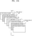
- FIGS. 13A to 13D illustrate an operation of an electronic apparatus of the related art.
- FIG. 13A illustrates a configuration of the electronic apparatus of the related art.
- the electronic apparatus of the related art may include a first display 1300, a second display 1310, and a lens array 1320.
- the lens array 1320 may be positioned between the first display 1300 and the second display 1310.
- the first display 1300 may include a first vertical polarizer 1304, a first cell 1302, and a first horizontal polarizer 1306, and the second display 1310 may include a second horizontal polarizer 1316, a second cell 1312, and a second vertical polarizer 1314.
- components of the electronic apparatus of the related art are not limited thereto, and the electronic apparatus may further include other components or include some of the components.
- FIG. 13B illustrates an example of polarized light having passed through the first display 1300 of the electronic apparatus of the related art.
- the first linear polarized light 1350 may be linear polarized light that has an amplitude X 0 and forms an angle of 0° with the X-axis.
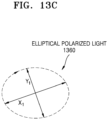
- FIG. 13C illustrates an example of polarized light having passed through the lens array 1320 of the electronic apparatus of the related art. Due to a birefringent feature of the lens array 1320, the first linear polarized light 1350 may change to elliptical polarized light 1360 while passing through the lens array 1320. For example, when the lens array 1320 has the quarter-wave plate feature, the first linear polarized light 1350 may change to the elliptical polarized light 1360 while passing through the lens array 1320.
- the elliptical polarized light 1360 may include a component having an amplitude X 1 in a direction of a fast axis (or a slow axis) of the lens array 1320 and a component having an amplitude Y 1 in the direction of the slow axis (or the fast axis).
- a relation between an amplitude of each component and an amplitude of the first polarized light 1350 may be expressed by Equation (7) below.
- X 1 2 + Y 1 2 X 0 2
- FIG. 13D illustrates an example of polarized light having passed through the second display 1310 of the electronic apparatus of the related art. Only a component parallel to an orientation of a gap in the second horizontal polarizer 1316 in the second display 1310 among components of elliptical polarized light having passed through the lens array 1320 may pass through the second horizontal polarizer 1316.
- the second linear polarized light 1370 may be linear polarized light that has an amplitude X 0 ' and forms an angle of 0° with the X-axis.
- the amplitude X 0 ' of the second linear polarized light 1370 may be less than the amplitude X 0 of the first linear polarized light 1350. As a result, the luminance of the second display 1310 may decrease.
- FIGS. 14A to 14D illustrate an operation of an electronic apparatus 1200 according to an embodiment of the disclosure.
- FIG. 14A illustrates a configuration of the electronic apparatus 1200 according to an embodiment of the disclosure.
- the electronic apparatus 1200 may include a first display 1400, a second display 1410, and a lens array 1420.
- the lens array 1420 may be positioned between the first display 1400 and the second display 1410.
- the first display 1400 may include a first vertical polarizer 1404, a first cell 1402, and a first horizontal polarizer 1406, and the second display 1410 may include a second horizontal polarizer 1416, a second cell 1412, and a second vertical polarizer 1414.
- components of the electronic apparatus 1200 are not limited thereto, and the electronic apparatus 1200 may further include other components or include some of the components.
- the first display 1400 and the second display 1410 may correspond to the display 1210 of FIG. 12
- the lens array 1420 may correspond to the lens array 1220 of FIG. 12 .
- the electronic apparatus 1200 may identify a rotation angle of a polarizer in a display for maximizing a luminance of the second display 1410, and rotate the polarizer in the display, based on the rotation angle. For example, the electronic apparatus 1200 may rotate the first horizontal polarizer 1406 in the first display 1400 by a first rotation angle 1430, i.e., ⁇ , and rotate the first vertical polarizer 1404 such that an orientation of a gap in the first vertical polarizer 1404 is perpendicular to an orientation of a gap in the first horizontal polarizer 1406.
- a first rotation angle 1430 i.e., ⁇
- the electronic apparatus 1200 may rotate the second horizontal polarizer 1416 in the second display 1410 by a second rotation angle 1440, i.e., ⁇ , and rotate the second vertical polarizer 1414 such that an orientation of a gap in the second vertical polarizer 1414 is perpendicular to an orientation of a gap in the second horizontal polarizer 1416.
- a second rotation angle 1440 i.e., ⁇
- FIG. 14B illustrates an example of polarized light having passed through the first display 1400 of the electronic apparatus 1200.
- the first horizontal polarizer 1406 when all of pieces of light from backlight are pieces of white light, only a component parallel to the orientation of the gap in the first horizontal polarizer 1406 in the first display 1400 among components of the pieces of white light may pass through the first horizontal polarizer 1406.
- the first linear polarized light 1450 may be linear polarized light that has an amplitude X 0 and forms an angle ⁇ with the X-axis.
- FIG. 14C illustrates an example of polarized light having passed through the lens array 1420.
- the first linear polarized light 1450 may change to elliptical polarized light 1460 while passing through the lens array 1420.
- the lens array 1420 has the quarter-wave plate feature
- the first linear polarized light 1450 may change to the elliptical polarized light 1460 while passing through the lens array 1420.
- the first linear polarized light 1450 having passed through the first horizontal polarizer 1406 may be parallel to the fast or slow axis of the lens array 1420 of forms a very small angle with the fast or slow axis of the lens array 1420.
- a component in a direction of the fast axis (or slow axis) of the lens array 1420 may have an amplitude X 1 and a component in a direction of the slow axis (or fast axis) may have a very low amplitude.
- a relation between the amplitude of the component in the fast axis (or the slow axis) and the amplitude of the first polarized light 1450 may be expressed by Equation (8) below.
- FIG. 14D illustrates an example of polarized light having passed through the second display 1410 of the electronic apparatus 1200.
- only a component parallel to an orientation of a gap in the second horizontal polarizer 1416 in the second display 1410 among components of elliptical polarized light having passed through the lens array 1420 may pass through the second horizontal polarizer 1416.
- the orientation of the gap in the second horizontal polarizer 1416 may be parallel to the fast or slow axis of the lens array 1420 or form a very small angle with the fast or slow axis of the lens array 1420.
- the second linear polarized light 1470 may be linear polarized light that has an amplitude X 0 ' and form an angle ⁇ with the X-axis.
- the X 0 ' may be similar to or the same as an amplitude X 0 of the first linear polarized light 1450. As a result, a degree of reduction in the luminance of the second display 1410 may be minimized due to the birefringence feature of the lens array 1420.
- FIGS. 15A and 15B are diagrams for describing a process of controlling a luminance by an electronic apparatus 1200 according to an embodiment of the disclosure.
- the electronic apparatus 1200 may identify a luminance of the second display 1410 by rotating the lens array 1420 and the second display 1410 while the first display 1400 is fixed.
- the electronic apparatus 1200 may identify the luminance of the second display 1410 by rotating the lens array 1420 and the polarizer in the second display 1410 while a rotation angle of the polarizer in the first display 1400 is fixed to 0°.
- FIG. 15A illustrates an example of a luminance of the second display 1410 when the lens array 1420 has the quarter-wave plate feature.
- the electronic apparatus 1200 may identify a luminance of the second display 1410 by rotating the polarizer in the second display 1410 while the fast or slow axis of the lens array 1420 is rotated by 0°, 30°, 60° and 90°.
- the second display 1410 may have a maximum luminance when a rotation angle of the fast or slow axis of the lens array 1420 is 0° and a rotation angle of the polarizer in the second display 1410 is 0°.
- FIG. 15B illustrates an example of a luminance of the second display 1410 when the lens array 1420 has the half-wave plate feature.
- the electronic apparatus 1200 may identify a luminance of the second display 1410 by rotating the polarizer in the second display 1410 while the fast or slow axis of the lens array 1420 is rotated by 0°, 30°, 60° and 90°.
- the second display 1410 may have a maximum luminance when a rotation angle of the fast or slow axis of the lens array 1420 is 0° and a rotation angle of the polarizer in the second display 1410 is 0°. Otherwise, the second display 1410 may have a maximum luminance when a rotation angle of the fast or slow axis of the lens array 1420 is 30° and a rotation angle of the polarizer in the second display 1410 is 60°. The second display 1410 may have a maximum luminance when a rotation angle of the fast or slow axis of the lens array 1420 is 45° and a rotation angle of the polarizer in the second display 1410 is 90°.
- FIGS. 16A and 16B are diagrams for describing a process of controlling a luminance by an electronic apparatus 1200 according to an embodiment of the disclosure.
- the electronic apparatus 1200 may identify an optimum rotation angle of the lens array 1420, and rotate the lens array 1420, based on the identified rotation angle. For example, the electronic apparatus 1200 may identify an optimum rotation angle of the lens array 1420 for reducing crosstalk, and rotate the lens array 1420, based on the identified rotation angle. According to another embodiment, the electronic apparatus 1200 may identify an optimum rotation angle for effectively reducing the moiré phenomenon, and rotate the lens array 1420, based on the identified rotation angle.
- the above description is only intended to provide an embodiment of the disclosure, and the electronic apparatus1200 may identify an optimum rotation angle of the lens array 1420 in consideration of the number of views, resolution, parallax, etc.
- the electronic apparatus 1200 may identify the luminance of the second display 1410 by simultaneously rotating the polarizers in the first display 1400 and the second display 1410 while the lens array 1420 is rotated by the identified rotation angle.
- the electronic apparatus 1200 may identify a luminance of the second display 1410 by simultaneously rotating the polarizers in the first display 1400 and the second display 1410 while the fast or slow axis of the lens array 1420 is rotated by 16.5°.
- FIG. 16A illustrates an example of a luminance of the second display 1410 when the polarizers in the first display 1400 and the second display 1410 are simultaneously rotated while the fast or slow axis of the lens array 1420 is rotated by 16.5.
- the second display 1410 when the difference between angles of the polarizers in the first display 1400 and the second display 1410 with the lens array 1420 is -5°, the second display 1410 may have a maximum luminance. Otherwise, when the difference between angles of the polarizers in the first display 1400 and the second display 1410 with the lens array 1420 is 85°, the second display 1410 may have a maximum luminance.
- FIG. 16B illustrates an example of a luminance of the second display 1410 when the polarizers in the first display 1400 and the second display 1410 are simultaneously rotated while the fast or slow axis of the lens array 1420 is rotated by 16.5.
- the second display 1410 when the polarizers in the first display 1400 and the second display 1410 rotate by 21.5°, the second display 1410 may have a maximum luminance of 1407. That is, as the polarizers in the first display 1400 and the second display 1410 rotate by 21.5°, the luminance of the second display 1410 may be higher by 34% than a luminance of 8513 of the second display 1410 when the polarizers in the first display 1400 and the second display 1410 do not rotate.
- a rotation angle of the polarizers in the first display 1400 and the second display 1410 for maximizing a luminance of the second display 1410 may vary according to an arrangement of the lens array 1420.
- FIGS. 16A and 16B illustrate a luminance when the lens array 1420 is inverted and thus angles of rotation of the polarizers in the first display 1400 and the second display 1410 for maximizing a luminance of the second display 1410 are different from each other.
- FIGS. 17A to 17E are diagrams for describing a process of controlling a luminance by an electronic apparatus 1200 according to an embodiment of the disclosure.
- FIG. 17A illustrates a configuration of the electronic apparatus 1200 according to an embodiment of the disclosure.
- the electronic apparatus 1200 may include a first display 1400, a second display 1410, and a lens array 1420.
- the lens array 1420 may be positioned between the first display 1400 and the second display 1410.
- the first display 1400 may include a first vertical polarizer 1404, a first cell 1402, and a first horizontal polarizer 1406, and the second display 1410 may include a second horizontal polarizer 1416, a second cell 1412, and a second vertical polarizer 1414.
- components of the electronic apparatus 1200 are not limited thereto, and the electronic apparatus 1200 may further include other components or include some of the components.
- the electronic apparatus 1200 may identify a rotation angle of a polarizer in a display for maximizing a luminance of the second display 1410, and rotate the polarizer in the display, based on the rotation angle. For example, the electronic apparatus 1200 may rotate the first horizontal polarizer 1406 in the first display 1400 by a first rotation angle 1730, and rotate the first vertical polarizer 1404 such that an orientation of a gap in the first vertical polarizer 1404 is perpendicular to an orientation of a gap in the first horizontal polarizer 1406.
- the electronic apparatus 1200 may rotate the second horizontal polarizer 1416 in the second display 1410 by a second rotation angle 1740, and rotate the second vertical polarizer 1414 such that an orientation of a gap in the second vertical polarizer 1414 is perpendicular to an orientation of a gap in the second horizontal polarizer 1416.
- the orientation of the gap in the first horizontal polarizer 1406 may be parallel to a slow axis 1755 of the lens array 1420.
- the orientation of the gap in the second horizontal polarizer 1416 may be parallel to the slow axis 1755 of the lens array 1420.
- FIG. 17B illustrates examples of a fast axis and a slow axis of the lens array 1420.
- the lens array 1420 may have the quarter-wave plate feature, and the fast axis 1750 and the slow axis 1755 of the lens array 1420 may be formed as illustrated in FIG. 17B .
- FIG. 17C illustrates an example of linear polarized light having passed through the first display 1400.
- linear polarized light 1760 may be linear polarized light that has an amplitude X 0 and is parallel to the slow axis 1755 of the lens array 1420.
- FIG. 17D illustrates an example of polarized light having passed through the lens array 1420.
- the amplitude of and an angle of polarization of the linear polarized light 1760 may be maintained.
- the linear polarized light 1760 may change to linear polarized light 1762 having the same amplitude and angle of polarization as the linear polarized light 1760 when the linear polarized light 1760 passes through the lens array 1420.
- FIG. 17E illustrates an example of polarized light having passed through the second display 1410 of the electronic apparatus 1200.
- only a component parallel to an orientation of a gap in the second horizontal polarizer 1416 in the second display 1410 among components of linear polarized light having passed through the lens array 1420 may pass through the second horizontal polarizer 1416.
- the linear polarized light 1764 may be linear polarized light having an amplitude X 0 and parallel to the slow axis 1755 of the lens array 1420.
- the amplitude X 0 of the linear polarized light 1764 may be the same as the amplitude X 0 of the linear polarized light 1760.
- the luminance of the second display 1410 may not reduce due to the birefringence feature of the lens array 1420.
- FIGS. 18A to 18E are diagrams for describing a process of controlling a luminance by an electronic apparatus 1200 according to an embodiment of the disclosure.
- FIG. 18A illustrates a configuration of the electronic apparatus 1200 according to an embodiment of the disclosure.
- the electronic apparatus 1200 may include a first display 1400, a second display 1410, and a lens array 1420.
- the lens array 1420 may be positioned between the first display 1400 and the second display 1410.
- the first display 1400 may include a first vertical polarizer 1404, a first cell 1402, and a first horizontal polarizer 1406, and the second display 1410 may include a second horizontal polarizer 1416, a second cell 1412, and a second vertical polarizer 1414.
- components of the electronic apparatus 1200 are not limited thereto, and the electronic apparatus 1200 may further include other components or include some of the components.
- the electronic apparatus 1200 may identify a rotation angle of a polarizer in a display for maximizing a luminance of the second display 1410, and rotate the polarizer in the display, based on the rotation angle. For example, the electronic apparatus 1200 may rotate the first horizontal polarizer 1406 in the first display 1400 by a first rotation angle 1830, and rotate the first vertical polarizer 1404 such that an orientation of a gap in the first vertical polarizer 1404 is perpendicular to an orientation of a gap in the first horizontal polarizer 1406.
- the electronic apparatus 1200 may rotate the second horizontal polarizer 1416 in the second display 1410 by a second rotation angle 1840, and rotate the second vertical polarizer 1414 such that an orientation of a gap in the second vertical polarizer 1414 is perpendicular to an orientation of a gap in the second horizontal polarizer 1416.
- the orientation of the gap in the first horizontal polarizer 1406 may be parallel to a fast axis 1850 of the lens array 1420.
- the orientation of the gap in the second horizontal polarizer 1416 may be parallel to the fast axis 1850 of the lens array 1420.
- FIG. 18B illustrates examples of a fast axis and a slow axis of the lens array 1420.
- the lens array 1420 may have the quarter-wave plate feature, and the fast axis 1850 and a slow axis 1855 of the lens array 1420 may be formed as illustrated in FIG. 18B .
- FIG. 18C illustrates an example of linear polarized light having passed through the first display 1410.
- linear polarized light 1860 may be linear polarized light that has an amplitude X 0 and is parallel to the fast axis 1850 of the lens array 1420.
- FIG. 18D illustrates an example of polarized light having passed through the lens array 1420.
- the amplitude of and an angle of polarization of the linear polarized light 1860 may be maintained.
- the linear polarized light 1860 may change to linear polarized light 1862 having the same amplitude and angle of polarization as the linear polarized light 1860 when the linear polarized light 1860 passes through the lens array 1420.
- FIG. 18E illustrates an example of polarized light having passed through the second display 1410 of the electronic apparatus 1200.
- only a component parallel to an orientation of a gap in the second horizontal polarizer 1416 in the second display 1410 among components of linear polarized light having passed through the lens array 1420 may pass through the second horizontal polarizer 1416.
- linear polarized light 1864 may be linear polarized light that has an amplitude X 0 and is parallel to the fast axis 1850 of the lens array 1420.
- the amplitude X 0 of the linear polarized light 1864 may be the same as the amplitude X 0 of the linear polarized light 1860.
- the luminance of the second display 1410 may not reduce due to the birefringence feature of the lens array 1420.
- FIGS. 19A to 19E are diagrams for describing a process of controlling a luminance by an electronic apparatus 1200 according to an embodiment of the disclosure.
- FIG. 19A illustrates a configuration of the electronic apparatus 1200 according to an embodiment of the disclosure.
- the electronic apparatus 1200 may include a first display 1400, a second display 1410, and a lens array 1420.
- the lens array 1420 may be positioned between the first display 1400 and the second display 1410.
- the first display 1400 may include a first vertical polarizer 1404, a first cell 1402, and a first horizontal polarizer 1406, and the second display 1410 may include a second horizontal polarizer 1416, a second cell 1412, and a second vertical polarizer 1414.
- components of the electronic apparatus 1200 are not limited thereto, and the electronic apparatus 1200 may further include other components or include some of the components.
- the electronic apparatus 1200 may identify a rotation angle of a polarizer in a display for maximizing a luminance of the second display 1410, and rotate the polarizer in the display, based on the rotation angle. For example, the electronic apparatus 1200 may rotate the first horizontal polarizer 1406 in the first display 1400 by a first rotation angle 1930, and rotate the first vertical polarizer 1404 such that an orientation of a gap in the first vertical polarizer 1404 is perpendicular to an orientation of a gap in the first horizontal polarizer 1406.
- the electronic apparatus 1200 may rotate the second horizontal polarizer 1416 in the second display 1410 by a second rotation angle 1940, and rotate the second vertical polarizer 1414 such that an orientation of a gap in the second vertical polarizer 1414 is perpendicular to an orientation of a gap in the second horizontal polarizer 1416.
- the first rotation angle 1930 of the first horizontal polarizer 1406 in the first display 1400 may be a certain value.
- the first rotation angle 1930 of the first horizontal polarizer 1406 may be 0° as shown in FIG. 19A .
- FIG. 19B illustrates examples of a fast axis and a slow axis of the lens array 1420.
- the lens array 1420 may have the half-wave plate feature, and a fast axis 1950 and a slow axis 1955 of the lens array 1420 may be formed as illustrated in FIG. 19B .
- FIG. 19C illustrates an example of linear polarized light having passed through the first display 1410.
- FIG. 19C illustrates an example of linear polarized light having passed through the first display 1410.
- the first horizontal polarizer 1406 when all of pieces of light from backlight are pieces of white light, only a component parallel to the orientation of the gap in the first horizontal polarizer 1406 in the first display 1400 among components of the pieces of white light may pass through the first horizontal polarizer 1406.
- an angle of the orientation of the gap in the first horizontal polarizer 1406 with the X-axis is 0° and thus the linear polarized light 1960 may be linear polarized light that has an amplitude X 0 and forms an angle of 0° with the X-axis.
- FIG. 19D illustrates an example of polarized light having passed through the lens array 1420.
- the amplitude of the linear polarized light 1960 may be maintained but an angle of polarization of the linear polarized light 1960 may change.
- the linear polarized light 1960 may rotate by -2 ⁇ to change to linear polarized light 1962 when passing through the lens array 1420.
- FIG. 19E illustrates an example of polarized light having passed through the second display 1410 of the electronic apparatus 1200.
- only a component parallel to an orientation of a gap in the second horizontal polarizer 1416 in the second display 1410 among components of linear polarized light having passed through the lens array 1420 may pass through the second horizontal polarizer 1416.
- the second horizontal polarizer 1416 is rotated to cause the orientation of the gap in the second horizontal polarizer 1416 to be parallel to the linear polarized light 1962 and thus linear polarized light 1964 may be linear polarized light having an amplitude X 0 and parallel to the linear polarized light 1962.
- the amplitude X 0 of the linear polarized light 1964 may be the same as the amplitude X 0 of the linear polarized light 1960.
- the luminance of the second display 1410 may not reduce due to the birefringence feature of the lens array 1420.
- FIGS. 20A to 20F are diagrams for describing a process of controlling a luminance by an electronic apparatus 1200 according to an embodiment of the disclosure.
- FIG. 20A illustrates a configuration of the electronic apparatus 1200 according to an embodiment of the disclosure.
- the electronic apparatus 1200 may include a first display 1400, a second display 1410, and a lens array 1420.
- the lens array 1420 may be positioned between the first display 1400 and the second display 1410.
- the first display 1400 may include a first vertical polarizer 1404, a first cell 1402, and a first horizontal polarizer 1406, and the second display 1410 may include a second horizontal polarizer 1416, a second cell 1412, and a second vertical polarizer 1414.
- components of the electronic apparatus 1200 are not limited thereto, and the electronic apparatus 1200 may further include other components or include some of the components.
- the electronic apparatus 1200 may identify a rotation angle of the lens array 1420 for maximizing a luminance of the second display 1410, and rotate the lens array 1420, based on the rotation angle. For example, the electronic apparatus 1200 may rotate the lens array 1420 by a rotation angle 2030.
- a fast axis 2050 or a slow axis 2055 of the lens array 1420 may be parallel to orientations of gaps in the first horizontal polarizer 1406 and the second horizontal polarizer 1416.
- FIG. 20B illustrates examples of a fast axis and a slow axis of the lens array 1420 before the lens array 1420 is rotated.
- the lens array 1420 may have the quarter-wave plate feature, and a fast axis 2040 and a slow axis 2045 of the lens array 1420 may be formed as illustrated in FIG. 20B .
- FIG. 20C illustrates examples of a fast axis and a slow axis of the lens array 1420 after the lens array 1420 is rotated.
- a fast axis 2050 and a slow axis 2055 of the lens array 1420 may be formed as illustrated in FIG. 20C after the lens array 1420 is rotated by the rotation angle 2030.
- FIG. 20D illustrates an example of linear polarized light having passed through the first display 1410.
- the first horizontal polarizer 1406 is not rotated and thus the linear polarized light 2060 may be linear polarized light having an amplitude X 0 and forming an angle of 0° with the X-axis.
- FIG. 20E illustrates an example of polarized light having passed through the lens array 1420.
- the fast axis 2050 or the slow shaft 2055 of the lens array 1420 is parallel to the linear polarized light 2060
- an amplitude of and an angle of polarization of the linear polarized light 2060 may be maintained
- the slow axis 2055 of the lens array 1420 is parallel to the linear polarized light 2060 due to the rotation of the lens array 1420 and thus the linear polarized light 2060 may change to linear polarized light 2062 having the same amplitude and angle of polarization as the linear polarized light 2060 when passing through the lens array 1420.
- FIG. 20F illustrates an example of polarized light having passed through the second display 1410 of the electronic apparatus 1200.
- only a component parallel to an orientation of a gap in the second horizontal polarizer 1416 in the second display 1410 among components of linear polarized light having passed through the lens array 1420 may pass through the second horizontal polarizer 1416.
- an orientation in a gap in the second horizontal polarizer 1416 is parallel to the slow axis 2055 of the lens array 1420 and thus the linear polarized light 2064 may be linear polarized light having an amplitude X 0 and parallel to the slow axis 2055 of the lens array 1420.
- the amplitude X 0 of the linear polarized light 2064 may be the same as the X 0 of the linear polarized light 2060.
- the luminance of the second display 1410 may not reduce due to the birefringence feature of the lens array 1420.
- FIGS. 21A to 20E are diagrams for describing a process of controlling a luminance by an electronic apparatus 1200 according to an embodiment of the disclosure.
- FIG. 21A illustrates a configuration of the electronic apparatus 1200 according to an embodiment of the disclosure.
- the electronic apparatus 1200 may include a first display 1400, a second display 1410, and a lens array 1420.
- the lens array 1420 may be positioned between the first display 1400 and the second display 1410.
- the first display 1400 may include a first vertical polarizer 1404, a first cell 1402, and a first horizontal polarizer 1406, and the second display 1410 may include a second horizontal polarizer 1416, a second cell 1412, and a second vertical polarizer 1414.
- components of the electronic apparatus 1200 are not limited thereto, and the electronic apparatus 1200 may further include other components or include some of the components.
- the electronic apparatus 1200 may identify a rotation angle of the polarizer in the second display 1410 for maximizing a luminance of the second display 1410 while the polarizer in the first display 1400 is not rotated.
- the electronic apparatus 1200 may identify a second rotation angle 2140 of the polarizer in the second display 1410 for maximizing a luminance of the second display 1410 while a first rotation angle 2130 of the polarizer in the first display 1400 is fixed to 0°.
- the electronic apparatus 1200 may rotate only the polarizer in the second display 1410, based on the identified second rotation angle 140. For example, the electronic apparatus 1200 may rotate the second horizontal polarizer 1416 in the second display 1410 by the second rotation angle 2140, and rotate the second vertical polarizer 1414 such that an orientation of a gap in the second vertical polarizer 1414 is perpendicular to an orientation of a gap in the second horizontal polarizer 1416.
- the orientation of the gap in the second horizontal polarizer 1416 may be parallel to the fast axis 2150 or the slow axis 2155 of the lens array 1420.
- FIG. 21B illustrates examples of a fast axis and a slow axis of the lens array 1420.
- the lens array 1420 may have the quarter-wave plate feature, and a fast axis 2150 and a slow axis 2155 of the lens array 1420 may be formed as illustrated in FIG. 21B .
- FIG. 21C illustrates an example of linear polarized light having passed through the first display 1410.
- the linear polarized light 2160 may be linear polarized light having an amplitude X 0 and forming an angle of 0° with the X-axis.
- FIG. 21D illustrates an example of polarized light having passed through the lens array 1420.
- the linear polarized light 2160 may change to elliptical polarized light 2162 when passing through the lens array 1420.
- the linear polarized light 2160 is not parallel to the fast axis 2150 or the slow axis 2155 of the lens array 1420 and thus may change to the elliptical polarized light 2162 having an amplitude X 1 in a direction of the fast axis 2150 and an amplitude Y 1 in a direction of the slow axis 2155 when passing through the lens array 1420.
- FIG. 21E illustrates an example of polarized light having passed through the second display 1410 of the electronic apparatus 1200.
- only a component parallel to an orientation of a gap in the second horizontal polarizer 1416 in the second display 1410 among components of linear polarized light having passed through the lens array 1420 may pass through the second horizontal polarizer 1416.
- the linear polarized light 1764 may be linear polarized light having an amplitude X 1 and parallel to the slow axis 2155 of the lens array 1420.
- the difference between the amplitude X 1 of the linear polarized light 2164 and the amplitude X 0 of the linear polarized light 2160 may be very small. As a result, a degree of reduction in the luminance of the second display 1410 may be minimized due to the birefringence feature of the lens array 1420.
- FIG. 22 is a flowchart of a process of controlling a luminance by an electronic apparatus according to an embodiment of the disclosure.
- the electronic apparatus may identify a luminance of a second display.
- the electronic apparatus may identify, for maximizing the luminance of the second display, a first rotation angle corresponding to a polarizer in a first display and a second rotation angle corresponding to a polarizer in the second display.
- the electronic apparatus may rotate a lens array, and identify the first rotation angle and the second rotation angle, based on a rotation angle of the lens array.
- the electronic apparatus may identify a rotation angle of the polarizer in the second display without rotating the polarizer in the first display. For example, the electronic apparatus may identify a second rotation angle of the polarizer in the second display for maximizing the luminance of the second display while a first rotation angle of the polarizer in the first display is fixed to 0°.
- the electronic apparatus may rotate the polarizer in the first display, based on the first rotation angle, and rotate the polarizer in the second display, based on the second rotation angle.
- orientations of gaps in the polarizers in the first and second displays may be parallel to a fast or slow axis of the lens array as the polarizers in the first and second displays are rotated.
- the first rotation angle corresponding to the polarizer in the first display may have a certain value.
- the orientation of the gap in the second display may be parallel to the fast or slow axis of the lens array.
Landscapes
- Engineering & Computer Science (AREA)
- Physics & Mathematics (AREA)
- Computer Hardware Design (AREA)
- General Physics & Mathematics (AREA)
- Theoretical Computer Science (AREA)
- Devices For Indicating Variable Information By Combining Individual Elements (AREA)
Applications Claiming Priority (3)
| Application Number | Priority Date | Filing Date | Title |
|---|---|---|---|
| KR20210064978 | 2021-05-20 | ||
| KR1020210156054A KR20220157276A (ko) | 2021-05-20 | 2021-11-12 | 휘도를 제어하기 위한 방법 및 장치 |
| PCT/KR2022/006747 WO2022245040A1 (ko) | 2021-05-20 | 2022-05-11 | 휘도를 제어하기 위한 방법 및 장치 |
Publications (2)
| Publication Number | Publication Date |
|---|---|
| EP4321908A1 true EP4321908A1 (de) | 2024-02-14 |
| EP4321908A4 EP4321908A4 (de) | 2024-10-09 |
Family
ID=84141742
Family Applications (1)
| Application Number | Title | Priority Date | Filing Date |
|---|---|---|---|
| EP22804895.5A Pending EP4321908A4 (de) | 2021-05-20 | 2022-05-11 | Verfahren und vorrichtung zur luminanzsteuerung |
Country Status (3)
| Country | Link |
|---|---|
| US (1) | US11842666B2 (de) |
| EP (1) | EP4321908A4 (de) |
| WO (1) | WO2022245040A1 (de) |
Family Cites Families (21)
| Publication number | Priority date | Publication date | Assignee | Title |
|---|---|---|---|---|
| JPH05122733A (ja) | 1991-10-28 | 1993-05-18 | Nippon Hoso Kyokai <Nhk> | 3次元画像表示装置 |
| GB2398130A (en) | 2003-02-05 | 2004-08-11 | Ocuity Ltd | Switchable active lens for display apparatus |
| JP4654570B2 (ja) | 2003-07-07 | 2011-03-23 | 日本電気株式会社 | 誘導ブリルアン散乱抑圧装置及びこれを用いた光ファイバ伝送システム |
| JP4751650B2 (ja) | 2004-06-11 | 2011-08-17 | 株式会社リコー | 微小光学素子、この微小光学素子を用いた空間光変調装置及びプロジェクタ装置 |
| JP4215058B2 (ja) * | 2006-01-19 | 2009-01-28 | エプソンイメージングデバイス株式会社 | 画像表示装置及び電子機器 |
| KR101255210B1 (ko) * | 2006-05-04 | 2013-04-23 | 삼성전자주식회사 | 다시점 입체 영상 디스플레이 장치 |
| JP4981394B2 (ja) * | 2006-09-28 | 2012-07-18 | 株式会社ジャパンディスプレイイースト | 表示装置 |
| US8432411B2 (en) * | 2007-05-18 | 2013-04-30 | Pure Depth Limited | Method and system for improving display quality of a multi-component display |
| US9343020B2 (en) | 2013-08-05 | 2016-05-17 | Massachusetts Institute Of Technology | Methods and apparatus for visual display |
| JP2015099321A (ja) * | 2013-11-20 | 2015-05-28 | 株式会社東芝 | 立体画像表示装置 |
| KR102260874B1 (ko) | 2014-11-13 | 2021-06-04 | 삼성디스플레이 주식회사 | 곡면형 액정 표시 장치 및 그 제조 방법 |
| KR20170089472A (ko) * | 2016-01-26 | 2017-08-04 | 삼성디스플레이 주식회사 | 3차원 영상 표시 장치 및 그 구동 방법 |
| JP6791034B2 (ja) * | 2017-06-16 | 2020-11-25 | 株式会社Jvcケンウッド | 表示システム、映像処理装置、画素ずらし表示装置、映像処理方法、表示方法、及びプログラム |
| CN107464524B (zh) * | 2017-08-25 | 2021-03-30 | 惠科股份有限公司 | 亮度补偿的优化方式 |
| CN109507829B (zh) * | 2017-09-15 | 2021-09-14 | 群创光电股份有限公司 | 显示设备 |
| US11448918B2 (en) | 2019-01-30 | 2022-09-20 | Samsung Electronics Co., Ltd. | Grating device, screen including the grating device, method of manufacturing the screen and display apparatus for augmented reality and/or virtual reality including the screen |
| US11808957B2 (en) * | 2019-02-25 | 2023-11-07 | Visteon Global Technologies, Inc. | System and method for adjusting light intensity in a display system |
| US11967028B2 (en) * | 2019-04-17 | 2024-04-23 | Newtonoid Technologies, L.L.C. | Watch having an intelligent display system |
| CN111624814B (zh) | 2020-06-15 | 2022-07-12 | 武汉华星光电技术有限公司 | 显示装置及显示优化方法 |
| US11067853B1 (en) | 2020-06-15 | 2021-07-20 | Wuhan China Star Optoelectronics Technology Co., Ltd. | Display device and display optimization method |
| CN112068314B (zh) * | 2020-09-29 | 2022-04-22 | 京东方科技集团股份有限公司 | 一种近眼显示装置 |
-
2022
- 2022-05-11 EP EP22804895.5A patent/EP4321908A4/de active Pending
- 2022-05-11 WO PCT/KR2022/006747 patent/WO2022245040A1/ko not_active Ceased
- 2022-05-20 US US17/750,078 patent/US11842666B2/en active Active
Also Published As
| Publication number | Publication date |
|---|---|
| WO2022245040A1 (ko) | 2022-11-24 |
| EP4321908A4 (de) | 2024-10-09 |
| US11842666B2 (en) | 2023-12-12 |
| US20220383791A1 (en) | 2022-12-01 |
Similar Documents
| Publication | Publication Date | Title |
|---|---|---|
| EP2183632B1 (de) | Verfahren und vorrichtung zur autofokussierung mit adaptiver flüssigkristalloptik | |
| US8786812B2 (en) | Liquid crystal display device | |
| US11474352B2 (en) | Optical system and method for providing expanded field of view | |
| KR101135757B1 (ko) | 입체 디스플레이 시스템 | |
| US9709863B2 (en) | Liquid crystal display device | |
| KR20210114793A (ko) | 도파관형 디스플레이 장치 | |
| WO2010070772A1 (ja) | 液晶フィルタ、位相差板及び光学ローパスフィルタ | |
| US9405138B2 (en) | Liquid crystal display device | |
| US11226512B2 (en) | Liquid crystal display device and display method | |
| CN115909913B (zh) | 一种显示模组及成像控制方法 | |
| JPH06118359A (ja) | 位相型空間光変調器 | |
| WO2016125624A1 (ja) | 表示装置 | |
| WO2023097056A1 (en) | Light guide display system for providing increased pixel density | |
| WO2002095494A2 (en) | Liquid-crystal display device | |
| JPH079560B2 (ja) | マッチドフィルタリング方法 | |
| EP4321908A1 (de) | Verfahren und vorrichtung zur luminanzsteuerung | |
| CN106842677A (zh) | 一种透明液晶显示面板及包含其的显示器 | |
| US5237437A (en) | Apparatus and method for a high contrast, wide angle, color, flat panel, liquid crystal display | |
| JPH1083030A (ja) | デジタル画像形成装置 | |
| KR20220157276A (ko) | 휘도를 제어하기 위한 방법 및 장치 | |
| US10768476B1 (en) | Display device | |
| JP2021128232A (ja) | 液晶表示装置 | |
| US12050320B2 (en) | Display device and electronic apparatus | |
| US7289189B2 (en) | Birefringent filter-based color generation scheme for a passive matrix display device | |
| KR20200044621A (ko) | 조리개 크기의 조절이 가능한 화상 인식 장치용 광 조절장치 |
Legal Events
| Date | Code | Title | Description |
|---|---|---|---|
| STAA | Information on the status of an ep patent application or granted ep patent |
Free format text: STATUS: THE INTERNATIONAL PUBLICATION HAS BEEN MADE |
|
| PUAI | Public reference made under article 153(3) epc to a published international application that has entered the european phase |
Free format text: ORIGINAL CODE: 0009012 |
|
| STAA | Information on the status of an ep patent application or granted ep patent |
Free format text: STATUS: REQUEST FOR EXAMINATION WAS MADE |
|
| 17P | Request for examination filed |
Effective date: 20231108 |
|
| AK | Designated contracting states |
Kind code of ref document: A1 Designated state(s): AL AT BE BG CH CY CZ DE DK EE ES FI FR GB GR HR HU IE IS IT LI LT LU LV MC MK MT NL NO PL PT RO RS SE SI SK SM TR |
|
| DAV | Request for validation of the european patent (deleted) | ||
| DAX | Request for extension of the european patent (deleted) | ||
| REG | Reference to a national code |
Ref country code: DE Ref legal event code: R079 Free format text: PREVIOUS MAIN CLASS: G02B0005300000 Ipc: G09G0003200000 |
|
| A4 | Supplementary search report drawn up and despatched |
Effective date: 20240911 |
|
| RIC1 | Information provided on ipc code assigned before grant |
Ipc: H04N 13/388 20180101ALI20240905BHEP Ipc: G02B 30/50 20200101ALI20240905BHEP Ipc: G02B 5/30 20060101ALI20240905BHEP Ipc: G09G 3/20 20060101AFI20240905BHEP |