EP4319989B1 - Reifen für ein landwirtschaftliches nutzfahrzeug mit gemischter verwendung - Google Patents
Reifen für ein landwirtschaftliches nutzfahrzeug mit gemischter verwendung Download PDFInfo
- Publication number
- EP4319989B1 EP4319989B1 EP22717640.1A EP22717640A EP4319989B1 EP 4319989 B1 EP4319989 B1 EP 4319989B1 EP 22717640 A EP22717640 A EP 22717640A EP 4319989 B1 EP4319989 B1 EP 4319989B1
- Authority
- EP
- European Patent Office
- Prior art keywords
- row
- equal
- circumferential
- tyre
- block
- Prior art date
- Legal status (The legal status is an assumption and is not a legal conclusion. Google has not performed a legal analysis and makes no representation as to the accuracy of the status listed.)
- Active
Links
Images


Classifications
-
- B—PERFORMING OPERATIONS; TRANSPORTING
- B60—VEHICLES IN GENERAL
- B60C—VEHICLE TYRES; TYRE INFLATION; TYRE CHANGING; CONNECTING VALVES TO INFLATABLE ELASTIC BODIES IN GENERAL; DEVICES OR ARRANGEMENTS RELATED TO TYRES
- B60C11/00—Tyre tread bands; Tread patterns; Anti-skid inserts
- B60C11/03—Tread patterns
- B60C11/13—Tread patterns characterised by the groove cross-section, e.g. for buttressing or preventing stone-trapping
- B60C11/1307—Tread patterns characterised by the groove cross-section, e.g. for buttressing or preventing stone-trapping with special features of the groove walls
-
- B—PERFORMING OPERATIONS; TRANSPORTING
- B60—VEHICLES IN GENERAL
- B60C—VEHICLE TYRES; TYRE INFLATION; TYRE CHANGING; CONNECTING VALVES TO INFLATABLE ELASTIC BODIES IN GENERAL; DEVICES OR ARRANGEMENTS RELATED TO TYRES
- B60C11/00—Tyre tread bands; Tread patterns; Anti-skid inserts
- B60C11/03—Tread patterns
- B60C11/0302—Tread patterns directional pattern, i.e. with main rolling direction
-
- B—PERFORMING OPERATIONS; TRANSPORTING
- B60—VEHICLES IN GENERAL
- B60C—VEHICLE TYRES; TYRE INFLATION; TYRE CHANGING; CONNECTING VALVES TO INFLATABLE ELASTIC BODIES IN GENERAL; DEVICES OR ARRANGEMENTS RELATED TO TYRES
- B60C11/00—Tyre tread bands; Tread patterns; Anti-skid inserts
- B60C11/03—Tread patterns
- B60C11/0306—Patterns comprising block rows or discontinuous ribs
-
- B—PERFORMING OPERATIONS; TRANSPORTING
- B60—VEHICLES IN GENERAL
- B60C—VEHICLE TYRES; TYRE INFLATION; TYRE CHANGING; CONNECTING VALVES TO INFLATABLE ELASTIC BODIES IN GENERAL; DEVICES OR ARRANGEMENTS RELATED TO TYRES
- B60C11/00—Tyre tread bands; Tread patterns; Anti-skid inserts
- B60C11/03—Tread patterns
- B60C11/0311—Patterns comprising tread lugs arranged parallel or oblique to the axis of rotation
-
- B—PERFORMING OPERATIONS; TRANSPORTING
- B60—VEHICLES IN GENERAL
- B60C—VEHICLE TYRES; TYRE INFLATION; TYRE CHANGING; CONNECTING VALVES TO INFLATABLE ELASTIC BODIES IN GENERAL; DEVICES OR ARRANGEMENTS RELATED TO TYRES
- B60C11/00—Tyre tread bands; Tread patterns; Anti-skid inserts
- B60C11/03—Tread patterns
- B60C11/0327—Tread patterns characterised by special properties of the tread pattern
- B60C11/033—Tread patterns characterised by special properties of the tread pattern by the void or net-to-gross ratios of the patterns
-
- B—PERFORMING OPERATIONS; TRANSPORTING
- B60—VEHICLES IN GENERAL
- B60C—VEHICLE TYRES; TYRE INFLATION; TYRE CHANGING; CONNECTING VALVES TO INFLATABLE ELASTIC BODIES IN GENERAL; DEVICES OR ARRANGEMENTS RELATED TO TYRES
- B60C11/00—Tyre tread bands; Tread patterns; Anti-skid inserts
- B60C11/03—Tread patterns
- B60C11/12—Tread patterns characterised by the use of narrow slits or incisions, e.g. sipes
- B60C11/1272—Width of the sipe
- B60C11/1281—Width of the sipe different within the same sipe, i.e. enlarged width portion at sipe bottom or along its length
-
- B—PERFORMING OPERATIONS; TRANSPORTING
- B60—VEHICLES IN GENERAL
- B60C—VEHICLE TYRES; TYRE INFLATION; TYRE CHANGING; CONNECTING VALVES TO INFLATABLE ELASTIC BODIES IN GENERAL; DEVICES OR ARRANGEMENTS RELATED TO TYRES
- B60C11/00—Tyre tread bands; Tread patterns; Anti-skid inserts
- B60C11/03—Tread patterns
- B60C11/13—Tread patterns characterised by the groove cross-section, e.g. for buttressing or preventing stone-trapping
- B60C11/1353—Tread patterns characterised by the groove cross-section, e.g. for buttressing or preventing stone-trapping with special features of the groove bottom
-
- B—PERFORMING OPERATIONS; TRANSPORTING
- B60—VEHICLES IN GENERAL
- B60C—VEHICLE TYRES; TYRE INFLATION; TYRE CHANGING; CONNECTING VALVES TO INFLATABLE ELASTIC BODIES IN GENERAL; DEVICES OR ARRANGEMENTS RELATED TO TYRES
- B60C11/00—Tyre tread bands; Tread patterns; Anti-skid inserts
- B60C11/03—Tread patterns
- B60C11/0311—Patterns comprising tread lugs arranged parallel or oblique to the axis of rotation
- B60C2011/0313—Patterns comprising tread lugs arranged parallel or oblique to the axis of rotation directional type
-
- B—PERFORMING OPERATIONS; TRANSPORTING
- B60—VEHICLES IN GENERAL
- B60C—VEHICLE TYRES; TYRE INFLATION; TYRE CHANGING; CONNECTING VALVES TO INFLATABLE ELASTIC BODIES IN GENERAL; DEVICES OR ARRANGEMENTS RELATED TO TYRES
- B60C11/00—Tyre tread bands; Tread patterns; Anti-skid inserts
- B60C11/03—Tread patterns
- B60C2011/0337—Tread patterns characterised by particular design features of the pattern
- B60C2011/0339—Grooves
- B60C2011/0341—Circumferential grooves
- B60C2011/0355—Circumferential grooves characterised by depth
-
- B—PERFORMING OPERATIONS; TRANSPORTING
- B60—VEHICLES IN GENERAL
- B60C—VEHICLE TYRES; TYRE INFLATION; TYRE CHANGING; CONNECTING VALVES TO INFLATABLE ELASTIC BODIES IN GENERAL; DEVICES OR ARRANGEMENTS RELATED TO TYRES
- B60C11/00—Tyre tread bands; Tread patterns; Anti-skid inserts
- B60C11/03—Tread patterns
- B60C2011/0337—Tread patterns characterised by particular design features of the pattern
- B60C2011/0339—Grooves
- B60C2011/0358—Lateral grooves, i.e. having an angle of 45 to 90 degees to the equatorial plane
- B60C2011/036—Narrow grooves, i.e. having a width of less than 3 mm
-
- B—PERFORMING OPERATIONS; TRANSPORTING
- B60—VEHICLES IN GENERAL
- B60C—VEHICLE TYRES; TYRE INFLATION; TYRE CHANGING; CONNECTING VALVES TO INFLATABLE ELASTIC BODIES IN GENERAL; DEVICES OR ARRANGEMENTS RELATED TO TYRES
- B60C11/00—Tyre tread bands; Tread patterns; Anti-skid inserts
- B60C11/03—Tread patterns
- B60C2011/0337—Tread patterns characterised by particular design features of the pattern
- B60C2011/0386—Continuous ribs
- B60C2011/0388—Continuous ribs provided at the equatorial plane
-
- B—PERFORMING OPERATIONS; TRANSPORTING
- B60—VEHICLES IN GENERAL
- B60C—VEHICLE TYRES; TYRE INFLATION; TYRE CHANGING; CONNECTING VALVES TO INFLATABLE ELASTIC BODIES IN GENERAL; DEVICES OR ARRANGEMENTS RELATED TO TYRES
- B60C11/00—Tyre tread bands; Tread patterns; Anti-skid inserts
- B60C11/03—Tread patterns
- B60C11/12—Tread patterns characterised by the use of narrow slits or incisions, e.g. sipes
- B60C11/1204—Tread patterns characterised by the use of narrow slits or incisions, e.g. sipes with special shape of the sipe
- B60C2011/1209—Tread patterns characterised by the use of narrow slits or incisions, e.g. sipes with special shape of the sipe straight at the tread surface
-
- B—PERFORMING OPERATIONS; TRANSPORTING
- B60—VEHICLES IN GENERAL
- B60C—VEHICLE TYRES; TYRE INFLATION; TYRE CHANGING; CONNECTING VALVES TO INFLATABLE ELASTIC BODIES IN GENERAL; DEVICES OR ARRANGEMENTS RELATED TO TYRES
- B60C2200/00—Tyres specially adapted for particular applications
- B60C2200/08—Tyres specially adapted for particular applications for agricultural vehicles
Definitions
- the present invention relates to a tire for a mixed-use agricultural vehicle, that is to say for road and field use, such as an agricultural tractor or an agro-industrial vehicle, and more particularly relates to its tread.
- a tire for an agricultural vehicle includes a tread, intended to come into contact with the ground via a rolling surface, the two axial ends of which are connected via two sidewalls with two beads ensuring the mechanical connection between the tire and the rim on which it is intended to be mounted.
- the circumferential (or longitudinal), axial (or transverse) and radial directions respectively designate a direction tangent to the tread surface and oriented in the direction of rotation of the tire, a direction parallel to the axis of rotation of the tire and a direction perpendicular to the axis of rotation of the tire.
- a radial (or meridian) plane is defined by a radial direction and the axial direction, and contains the axis of rotation of the tire.
- a circumferential plane is defined by a radial direction and a circumferential direction, and is therefore perpendicular to the axis of rotation of the tire.
- the circumferential plane passing through the middle of the tread is called the median circumferential plane or equatorial plane.
- the tread of a tire for an agricultural vehicle generally comprises a sculpture constituted by a plurality of raised elements extending radially outward from a bearing surface to the rolling surface, and separated from each other by hollows.
- a tread for an agricultural vehicle usually comprises tread elements in the form of bars.
- a bar generally has an elongated, generally parallelepipedal shape, continuous or discontinuous, and consisting of at least one rectilinear or curvilinear portion.
- a bar is separated from adjacent bars by hollows or grooves.
- a bar extends axially from a median zone of the tread to its axial ends or shoulders.
- a bar comprises a contact face, positioned in the tread surface and intended to come into full contact with the ground, a leading face, intersecting the tread surface and the edge of which intersects with the latter is intended to come into contact first with the ground, a trailing face, intersecting the rolling surface and whose intersection edge with it is intended to come into contact last with the ground, and two lateral faces.
- the lugs are distributed circumferentially at a constant or variable pitch, measured between the respective mean lines of two consecutive lugs, and are generally arranged on either side of the equatorial plane of the tire, so as to form a V-shaped pattern, the tip of the V-shaped pattern (or chevron pattern) being intended to enter the contact area with the ground first.
- the lugs generally have symmetry with respect to the equatorial plane of the tire, with most often a circumferential offset between the two rows of lugs, obtained by a rotation about the axis of the tire of one half of the tread relative to the other half of the tread.
- a tire for an agricultural vehicle is intended to run on various types of ground such as more or less compacted earth in fields, unpaved access roads to fields and paved road surfaces. Given the diversity of use, in the field and on the road, a tire for an agricultural vehicle must offer a compromise in performance between, but not limited to, traction in the field on soft ground, resistance to tearing, resistance to wear on the road, resistance to forward movement and vibration comfort on the road.
- the road performance of the tyre becomes essential.
- the tyre initially designed for efficiency in the field, must also have high road performance, in particular in terms of energy efficiency and wear life.
- Energy efficiency means a significant contribution to the fuel economy of the vehicle, thanks to limited resistance to forward movement, and in particular rolling resistance.
- Concerning wear on the road, the tyre must allow high mileage on the road, thanks to a wear rate that is not too fast and controlled forms of wear on its tread.
- the search for the compromise in road performance described above must not lead to a deterioration in field performance, such as traction capacity and flotation, i.e. the ability to not sink deeply into the ground.
- the inventors set themselves the objective of proposing an optimal compromise between rolling resistance and the wear life of a tire for an agricultural vehicle, in road use, without degrading either the grip when braking on the road, or the essential performances in the field such as traction capacity and flotation.
- the tread of a tire according to the invention comprises sculpture elements which are not traditional bars, extending axially from a median zone of the tread to its axial ends or shoulders, but blocks distributed across the width of the tread.
- These blocks are arranged in five circumferential rows: a middle row, two intermediate rows, axially positioned on either side of the middle row, and two lateral rows, respectively axially positioned outside an intermediate row.
- the arrangement of the respective blocks of a lateral row and the neighboring intermediate row constitutes a system of partial bars.
- Any block comprises a contact face, positioned in the rolling surface and intended to come into full contact with the ground, a leading face, intersecting the rolling surface and whose edge of intersection with it is intended to come into contact first with the ground, a trailing face, intersecting the rolling surface and whose edge of intersection with it is intended to come into contact last with the ground, and two lateral faces.
- the leading and trailing faces respectively, not necessarily contained in a plane, are generally characterized by the average angle that they form with a radial direction of the tire.
- Any block can be geometrically characterized by a radial height H in a radial direction, an axial width A in an axial direction and a length circumferential B in a circumferential direction.
- H, A and B are average values measured on the block.
- the axial width and the circumferential length vary over the height of the tread element: they can, for example, decrease from the bearing surface at the bottom of the hollow to the rolling surface, due to the inclination of the faces of the block.
- the radial height H is generally at least equal to 50 mm and most often at least equal to 60 mm. From these three dimensions H, A and B, a circumferential slenderness H/B, an axial slenderness H/A and a surface aspect ratio B/A determining the rigidities of the tread element can be defined for a given block.
- a circumferential hollow in a broad sense, forms, with the circumferential direction, an angle at most equal to 30°.
- its mean line forms an average angle, with respect to the circumferential direction of the tire, which is not zero, but included in the range of values [0°; 30°]. Its mean line forms a smaller inclination with respect to the circumferential direction than with respect to the axial direction.
- the hollow is therefore not strictly circumferential, but globally circumferential.
- transverse hollow in a broad sense, forms, with the circumferential direction, an angle at least equal to 60°.
- its mean line forms an average angle, with respect to the circumferential direction of the tire, which is not zero, but included in the range of values [60°; 90°]. Its mean line forms a greater inclination with respect to the circumferential direction than with respect to the axial direction.
- the hollow is therefore not strictly transverse, but globally transverse.
- a hollow is delimited by the two walls of the blocks that it separates.
- the blocks deform as they pass through the contact area of the tire with the ground while rolling, these walls tend to move closer together and the hollow that they delimit to close.
- These deformations depend on the mechanical stresses applied to the tire while rolling, these being themselves functions of the conditions of use of the tire.
- the conditions of use (load, speed, pressure) of a tire for agricultural vehicles are defined in standards, such as, for example, the "ETRTO” standard or “European Tire and Rim Technical Organization” in its “Standards Manual-2019” (Standards Manual 2019), in the section devoted to "Agricultural equipment tyres”.
- the walls of blocks delimiting a hollow may or may not come into contact with each other at least in part, that is to say that the hollow may or may not close.
- the hollow When there is no contact of the walls, the hollow is called a groove.
- the hollow When there is at least partial contact of the walls, the hollow is called an incision.
- a hollow is generally characterized geometrically by a width and a depth.
- the width of a hollow is measured perpendicular to the average surface of the hollow, positioned at an equal distance from the walls delimiting the hollow, and at the level of the rolling surface, or possibly in the vicinity of it in the event of the presence of chamfers on the blocks facing each other.
- the depth of the hollow is measured perpendicular to the rolling surface, between the emerging surface and the bottom of the hollow.
- two consecutive blocks of the middle row are separated by a transverse hollow having a width at most equal to 2.5 mm.
- a middle row transverse hollow is an incision, likely to close at least partially as it passes through the contact patch.
- the middle row consisting of blocks separated by incisions, constitutes a quasi-continuous rib incised periodically, which is favorable with respect to wear and rolling resistance performances in road use. Due to the small thickness of the middle transverse hollows, the volume of rubber material of the middle portion, intended to be worn by abrasion, is high, which is favorable to the service life with respect to wear. In addition, the surface area of rubber material of the middle portion, intended to come into contact with the ground, is also high, which reduces the ground contact pressures, and therefore abrasion, and consequently wear.
- the average circumferential slenderness of any block of the middle row is at least equal to 0.95 and at most equal to 1.15.
- a circumferential slenderness of a middle row block close to 1 is considered optimal with respect to the compromise, for the middle row, between its circumferential flattening, for wear and rolling resistance, and the level of slip obtained in the contact patch, for braking on a wet road.
- each block of each intermediate row comprises a leading face, in the circumferential rolling direction of the tire, forming, with a radial direction of the tire, an average angle at least equal to 30°.
- An average intermediate row block leading face angle of at least 30° makes it possible to have an intermediate block with a high material volume and high circumferential rigidity.
- a high material volume ensures a satisfactory wear life.
- High circumferential rigidity limits sliding of the intermediate row block in the contact area, and therefore abrasion, and consequently wear.
- circumferential deformations of the intermediate row block, by Poisson effects and in shear, are also limited. This results in less energy dissipation of the rubber material in the intermediate row blocks, which reduces rolling resistance.
- an average angle of attack face of intermediate row block at least equal to 30°, therefore high, makes it possible to increase the cohesion of the ground in front of and under the block, which makes it possible to develop a greater traction force.
- the average circumferential slenderness of any block of each lateral row is at most equal to 0.9.
- the reduction in the average circumferential slenderness of any block of each lateral row is achieved by an increase in the circumferential length of the block, which makes it possible to have a large volume of material to be worn, favorable to wear, and a high circumferential rigidity.
- a high volume of material makes it possible to guarantee a satisfactory wear life.
- a high circumferential rigidity limits the sliding of the intermediate row block in the contact patch, and therefore the abrasion, and consequently the wear.
- the circumferential deformations of the intermediate row block by Poisson effects and in shear, are also limited. This results in less energy dissipation of the rubber material in the intermediate row blocks, which reduces the rolling resistance.
- the middle row has an axial width at least equal to 15% and at most equal to 25% of the axial width of the tread.
- the axial width of the middle row must be sufficient so that the desired technical advantages in terms of wear and rolling resistance in road use are significant, but not too high so that the traction function in the field can be ensured correctly.
- the middle row has a local volumetric hollow rate of at most 20%.
- the proportion of gullets in a tread is usually quantified by an overall gullet volume ratio, defined as the ratio between the gullet volume and the total volume of the tread assumed to be gullet-free corresponding to the geometric volume delimited by the bearing surface and the rolling surface.
- the overall gullet volume ratio is also called the overall gullet volume ratio. Since the tread surface varies with tread wear, the overall gullet volume ratio generally, but not necessarily, varies with the level of wear. Thus, the overall gullet volume ratio can be defined for a new condition or for a given state of wear. For example, a tire for a drive wheel of an agricultural tractor in new condition has an overall gullet volume ratio generally at least equal to 50% and often at least equal to 60%. In the following, the expression "overall gullet volume ratio" implicitly means "overall gullet volume ratio in new condition".
- a local volumetric void ratio can also be defined for any portion of tread, extending circumferentially over the entire circumference of the tire and extending axially from a first circumferential plane to a second circumferential plane, the distance between these two circumferential planes representing the axial width, more simply called width, of the portion of tread.
- the local volumetric void ratio is defined as the ratio between the volume of voids and the total volume of the portion of tread assumed to be void-free, corresponding to the geometric volume delimited by the bearing surface, the rolling surface and the two circumferential planes.
- the local volumetric void ratio is also called the local volumetric notch ratio.
- the local volumetric void ratio can be defined for a new condition or for a given state of wear.
- the expression "local volumetric hollow rate” implicitly means "local volumetric hollow rate in new condition”.
- a local volumetric hollow rate of at most 20%, for the middle row, guarantees a significant favorable impact on wear and rolling resistance performance, in road use.
- any transverse hollow separating two consecutive blocks of the middle row forms, with the circumferential direction, an angle at least equal to 70°.
- the circumferential flattening of the middle row is facilitated by a transverse hollow angle as close as possible to the axial direction, i.e. as close as possible to 90°.
- any transverse hollow separating two consecutive blocks of the middle row has a depth at least equal to 50%, preferably at least equal to 70%, of the average radial height of the block.
- the middle row transverse hollow depth is insufficient to ensure a hinge effect allowing circumferential flattening of the middle row with a significant impact on rolling resistance.
- any transverse hollow separating two consecutive blocks of the middle row is extended radially inwards by a cavity.
- each intermediate row has an axial width at least equal to 15% and at most equal to 25% of the axial width of the tread.
- This range of axial width values of each intermediate row guarantees effective field traction over a significant portion of the tread.
- each intermediate row has a local volumetric hollow rate of at least 40%, preferably at least 55%.
- the average circumferential slenderness of any block respectively of each intermediate row is at least equal to 0.5 and at most equal to 1.
- An average circumferential slenderness of any intermediate row block in the range of values [0.5; 1], combined with an average leading face angle of said block at least equal to 30°, makes it possible to obtain an optimum circumferential rigidity of the block with respect to the compromise between road performance of wear and rolling resistance and traction in the field.
- any block of an intermediate row comprises a leading face forming, with a radial direction of the tire, an average angle at least equal to 35°.
- each lateral row has an axial width at least equal to 15% and at most equal to 25% of the axial width of the tread.
- each side row has a local volumetric hollow rate of at least 40%, preferably at least 55%.
- the average circumferential slenderness of any block respectively of each lateral row is at most equal to 0.8.
- the average circumferential slenderness of any block respectively of each lateral row is at least equal to 0.6.
- An average circumferential slenderness of any side row block in the range of values [0.6; 0.8] allows to obtain an optimum circumferential stiffness of the block with respect to the compromise between road performance of wear and rolling resistance and performance in traction field and earth evacuation.
- any block of a lateral row comprises a leading face forming, with a radial direction of the tire, an average angle at least equal to 10° and at most equal to 30°.
- transverse hollows separating two consecutive blocks of side row become too small to guarantee sufficient traction capacity and soil evacuation (or clearing) capacity.
- a reduction in the width of the transverse hollows can be at least partly compensated by an increase in the depth of the transverse hollows.
- each block of a lateral row comprises a leading face and a trailing face forming, with a radial direction of the tire, respective average angles equal in absolute value.
- This configuration therefore implies a symmetry of the inclinations of the leading and trailing faces of a lateral row block.
- each intermediate and lateral row comprises at least 26 blocks.
- each intermediate and lateral row comprises at most 32 blocks.
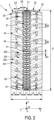
- the tire 1 for an agricultural vehicle comprises a tread 2 consisting of blocks (31, 32, 33), two by two separated by hollows (41, 42, 43, 51, 52) and arranged, in the width of the tread 2, in a middle row 21, two intermediate rows 22 and two lateral rows 23.
- the hollows (41, 42, 43, 51, 52) are either transverse hollows (41, 42, 43) or circumferential hollows (51, 52).
- the tire 1 for an agricultural vehicle having an outside diameter D in a state not mounted on a rim and not inflated, comprises a tread 2 having an axial width L, in an axial direction YY', and consisting of blocks (31, 32, 33), two by two separated by hollows (41, 42, 43, 51, 52) and arranged, in the width of the tread 2, in a middle row 21, two intermediate rows 22 and two lateral rows 23.
- the hollows (41, 42, 43, 51, 52) are either transverse hollows (41, 42, 43), forming, with a circumferential direction XX' of the tire 1, an angle at least equal to 60°, or circumferential hollows (51, 52), forming, with the circumferential direction XX', an angle at most equal to 30°.
- the middle row 21, having an axial width L1 is centered on a median circumferential plane E of the tire.
- the two intermediate rows 22, each having an axial width L2 are axially positioned on either side of the middle row 21 and separated therefrom by circumferential hollows 51, each having a width E2.
- the two lateral rows 23, having each an axial width L3, are respectively axially positioned outside an intermediate row 22 and separated therefrom by a circumferential hollow 52, having a width E3.
- Each respectively median 21, intermediate 22 and lateral 23 row is constituted by a circumferential distribution of blocks (31, 32, 33) two by two separated by transverse hollows (41, 42, 43) and each having an average circumferential length (B1, B2, B3).
- the circumferential length B1 of a block 31 of median row 21 is the circumferential distance measured between the two transverse hollows 41, of the incision type, delimiting it.
- the circumferential length B2 of a block 32 of intermediate row 22 is the average circumferential distance measured between a leading face 321 and a trailing face 322 of said block 32.
- the circumferential length B3 of a block 33 of lateral row 23 is the average circumferential distance measured between a leading face 331 and a trailing face 332 of said block 33.
- the blocks 33 of the same lateral row 23 extend axially outwards in the extension of the blocks 32 of the adjacent intermediate row 22, such that any set of two blocks (33, 32) respectively of lateral row 23 and intermediate row 22, in the extension of one another, forms a bar.
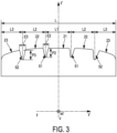
- FIG. 3 is a meridian sectional view of a tread of a tire according to the invention.
- the tread has an axial width L and is divided into a middle row 21 having an axial width L1, two intermediate rows 22 each having an axial width L2 and two lateral rows 23 each having an axial width L3.
- Each intermediate row 22 is respectively separated from the middle row 21 by a circumferential hollow 51 having a width E2 and a depth P2, and from the closest lateral row 23 by a circumferential hollow 52 having a width E3 and a depth P3.
- FIG 4 is a circumferential sectional view, along a plane XZ, of a portion of a middle row 21 of a tread of a tire according to the invention.
- the middle row 21 is formed by a circumferential distribution of blocks 31, each having a circumferential length B1 and a height H1.
- the blocks 31 are separated in pairs by transverse hollows 41, of the incision type, having a width E1.
- two consecutive blocks 31 of the middle row 21 are separated by a transverse hollow 41 having a width E1 at most equal to 2.5 mm.
- there is an alternation of transverse incisions 41 having respectively a depth H1 and a lower depth H1. This choice makes it possible to facilitate the manufacture of the tire, by reducing the effort necessary for demolding the tire after baking thanks to a reduced depth of some of the transverse incisions.
- FIG. 5 is a circumferential sectional view, along a plane XZ, of a portion of an intermediate row 22 of a tread of a tire according to the invention.
- the intermediate row 22 is constituted by a circumferential distribution of blocks 32, each having a circumferential length B2, average distance measured between a leading face 321 and a trailing face 322, and a height H2.
- the blocks 32 are separated in pairs by transverse hollows 42, of the groove type.
- each block 32 of each intermediate row 22 comprises a leading face 321, along the circumferential rolling direction of the tire, forming, with a radial direction ZZ' of the tire, an average angle D2 at least equal to 30°, and a trailing face 322 forming, with the radial direction ZZ' of the tire, an average angle D'2.
- FIG. 6 is a circumferential sectional view, along a plane XZ, of a portion of a lateral row 23 of a tread of a tire according to the invention.
- the lateral row 23 is constituted by a circumferential distribution of blocks 33, each having a circumferential length B3, average distance measured between a leading face 331 and a trailing face 332, and a height H3.
- the blocks 33 are separated in pairs by transverse hollows 43, of the groove type.
- the average circumferential slenderness of any block 33 of each lateral row 23 is at most equal to 0.9.
- each block 33 of each lateral row 23 comprises a leading face 331, in the circumferential rolling direction of the tire, forming, with a radial direction ZZ' of the tire, a mean angle D3 at least equal to 10° and at most equal to 30°, and a trailing face 332 forming, with the radial direction ZZ' of the tire, a mean angle D'3.
- the invention was more particularly studied for an agricultural tire of dimension 600/70 R 30.
- the inventors compared, on digital simulations and/or on internal tests, the performances of the invention and those of a reference tire 600/70 R 30 Michelin MACHXBIB.
- the wear life defined as the mileage traveled on the road before removal of the tire at complete wear, for the tire according to the invention, is 20% greater than that of the reference tire.
Landscapes
- Engineering & Computer Science (AREA)
- Mechanical Engineering (AREA)
- Tires In General (AREA)
Claims (18)
- Reifen (1) für ein landwirtschaftliches Fahrzeug, der eine Lauffläche (2) beinhaltet, die eine axiale Breite (L) aufweist und aus Blöcken (31, 32, 33) besteht, die jeweils paarweise durch Hohlräume (41, 42, 43, 51, 52) getrennt sind und in der Breite der Lauffläche (2) gemäß einer mittleren Reihe (21), zwei Zwischenreihen (22) und zwei seitlichen Reihen (23) eingerichtet sind,- wobei die Hohlräume (41, 42, 43, 51, 52) entweder Querhohlräume (41, 42, 43), die mit einer Umfangsrichtung (XX') des Reifens (1) einen Winkel von mindestens 60° bilden, oder Umfangshohlräume (51, 52), die mit der Umfangsrichtung (XX') einen Winkel von höchstens 30° bilden, sind,- wobei die mittlere Reihe (21) auf eine Umfangsmittelebene (E) des Reifens zentriert ist, die zwei Zwischenreihen (22) axial zu beiden Seiten der mittleren Reihe (21) positioniert und von dieser durch Umfangshohlräume (51) getrennt sind und die zwei seitlichen Reihen (23) jeweils axial auf der Außenseite einer Zwischenreihe (22) positioniert und von dieser durch einen Umfangshohlraum (52) getrennt sind,- wobei jede mittlere (21), Zwischen- (22) bzw. seitliche (23) Reihe aus einer Umfangsverteilung von Blöcken (31, 32, 33) besteht, die jeweils paarweise durch Querhohlräume (41, 42, 43) getrennt sind und jeweils eine mittlere radiale Höhe (H1, H2, H3), eine mittlere Umfangslänge (B1, B2, B3) und einen mittleren Schlankheitsgrad in Umfangsrichtung, der als das Verhältnis zwischen der mittleren radialen Höhe und der mittleren Umfangslänge des Blocks definiert ist, aufweisen,- wobei sich die Blöcke (33) einer gleichen seitlichen Reihe (23) in der Verlängerung der Blöcke (32) der benachbarten Zwischenreihe (22) axial nach außen erstrecken, sodass jede Anordnung von zwei Blöcken (33, 32) jeweils einer seitlichen Reihe (23) und einer Zwischenreihe (22) in der gegenseitigen Verlängerung einen Stollen bildet, wobei der mittlere Schlankheitsgrad in Umfangsrichtung jedes Blocks (33) jeder seitlichen Reihe (23) höchstens 0,9 beträgt, dadurch gekennzeichnet, dass zwei aufeinanderfolgende Blöcke (31) der mittleren Reihe (21) durch einen Querhohlraum (41) getrennt sind, der eine Breite (E1) von höchstens 2,5 mm aufweist, dass der mittlere Schlankheitsgrad in Umfangsrichtung jedes Blocks (31) der mittleren Reihe (21) mindestens 0,95 und höchstens 1,15 beträgt und dass jeder Block (32) jeder Zwischenreihe (22) eine Vorderfläche (321) gemäß der Rollumfangsrichtung des Reifens beinhaltet, die mit einer radialen Richtung (ZZ') des Reifens einen mittleren Winkel (D2) von mindestens 30° bildet.
- Reifen (1) nach Anspruch 1, wobei die mittlere Reihe (21) eine axiale Breite (L1) von mindestens 15 % und höchstens 25 % der axialen Breite (L) der Lauffläche (2) aufweist.
- Reifen (1) nach einem der Ansprüche 1 oder 2, wobei die mittlere Reihe (21) einen lokalen volumenbezogenen Hohlraumanteil von höchstens 20 % aufweist.
- Reifen (1) nach einem der Ansprüche 1 bis 3, wobei jeder Querhohlraum (41), der zwei aufeinanderfolgende Blöcke (31) der mittleren Reihe (21) trennt, mit der Umfangsrichtung (XX') einen Winkel von mindestens 70° bildet.
- Reifen (1) nach einem der Ansprüche 1 bis 4, wobei jeder Querhohlraum (41), der zwei aufeinanderfolgende Blöcke (31) der mittleren Reihe (21) trennt, eine Tiefe (P1) von mindestens 50 %, vorzugsweise mindestens 70 %, der mittleren radialen Höhe (H1) eines Blocks (31) aufweist.
- Reifen (1) nach einem der Ansprüche 1 bis 5, wobei jeder Querhohlraum (41), der zwei aufeinanderfolgende Blöcke (31) der mittleren Reihe (21) trennt, durch eine Aushöhlung (411) radial nach innen verlängert ist.
- Reifen (1) nach einem der Ansprüche 1 bis 6, wobei jede Zwischenreihe (22) eine axiale Breite (L2) von mindestens 15 % und höchstens 25 % der axialen Breite (L) der Lauffläche (2) aufweist.
- Reifen (1) nach einem der Ansprüche 1 bis 7, wobei jede Zwischenreihe (22) einen lokalen volumenbezogenen Hohlraumanteil von mindestens 40 %, vorzugsweise mindestens 55 %, aufweist.
- Reifen (1) nach einem der Ansprüche 1 bis 8, wobei der mittlere Schlankheitsgrad in Umfangsrichtung jedes Blocks (32) jeder jeweiligen Zwischenreihe (22) mindestens 0,5 und höchstens 1,0 beträgt.
- Reifen (1) nach einem der Ansprüche 1 bis 9, wobei jeder Block (32) einer Zwischenreihe (22) eine Vorderfläche (321) beinhaltet, die mit einer radialen Richtung (ZZ') des Reifens einen mittleren Winkel (D2) von mindestens 35° bildet.
- Reifen (1) nach einem der Ansprüche 1 bis 10, wobei jede seitliche Reihe (23) eine axiale Breite (L3) von mindestens 15 % und höchstens 25 % der axialen Breite (L) der Lauffläche (2) aufweist.
- Reifen (1) nach einem der Ansprüche 1 bis 11, wobei jede seitliche Reihe (23) einen lokalen volumenbezogenen Hohlraumanteil von mindestens 40 %, vorzugsweise mindestens 55 %, aufweist.
- Reifen (1) nach einem der Ansprüche 1 bis 12, wobei der mittlere Schlankheitsgrad in Umfangsrichtung jedes Blocks (33) jeder jeweiligen seitlichen Reihe (23) höchstens 0,8 beträgt.
- Reifen (1) nach einem der Ansprüche 1 bis 13, wobei der mittlere Schlankheitsgrad in Umfangsrichtung jedes Blocks (33) jeder jeweiligen seitlichen Reihe (23) mindestens 0,6 beträgt.
- Reifen (1) nach einem der Ansprüche 1 bis 14, wobei jeder Block (33) einer seitlichen Reihe (23) eine Vorderfläche (331) beinhaltet, die mit einer radialen Richtung (ZZ') des Reifens einen mittleren Winkel (D3) von mindestens 10° und höchstens 30° bildet.
- Reifen (1) nach einem der Ansprüche 1 bis 15, wobei jeder Block (33) einer seitlichen Reihe (23) eine Vorderfläche (331) und eine Hinterfläche (332) beinhaltet, die mit einer radialen Richtung (ZZ') des Reifens jeweilige mittlere Winkel (D3, D'3) bilden, die vom Absolutwert her gleich sind.
- Reifen (1) nach einem der Ansprüche 1 bis 16, wobei die Umfangsverteilung von Blöcken (31, 32, 33) jeder Zwischen- (22) und seitlichen (23) Reihe mindestens 26 Blöcke beinhaltet.
- Reifen (1) nach einem der Ansprüche 1 bis 17, wobei die Umfangsverteilung von Blöcken (31, 32, 33) jeder Zwischen- (22) und seitlichen (23) Reihe höchstens 32 Blöcke beinhaltet.
Applications Claiming Priority (2)
| Application Number | Priority Date | Filing Date | Title |
|---|---|---|---|
| FR2103624A FR3121631B1 (fr) | 2021-04-09 | 2021-04-09 | Pneumatique pour véhicule agricole à usage mixte |
| PCT/FR2022/050574 WO2022214750A1 (fr) | 2021-04-09 | 2022-03-28 | Pneumatique pour véhicule agricole à usage mixte |
Publications (2)
| Publication Number | Publication Date |
|---|---|
| EP4319989A1 EP4319989A1 (de) | 2024-02-14 |
| EP4319989B1 true EP4319989B1 (de) | 2025-01-22 |
Family
ID=76730693
Family Applications (1)
| Application Number | Title | Priority Date | Filing Date |
|---|---|---|---|
| EP22717640.1A Active EP4319989B1 (de) | 2021-04-09 | 2022-03-28 | Reifen für ein landwirtschaftliches nutzfahrzeug mit gemischter verwendung |
Country Status (6)
| Country | Link |
|---|---|
| US (1) | US12459304B2 (de) |
| EP (1) | EP4319989B1 (de) |
| CN (1) | CN117120276A (de) |
| BR (1) | BR112023020564A2 (de) |
| FR (1) | FR3121631B1 (de) |
| WO (1) | WO2022214750A1 (de) |
Families Citing this family (4)
| Publication number | Priority date | Publication date | Assignee | Title |
|---|---|---|---|---|
| USD1086978S1 (en) * | 2021-03-18 | 2025-08-05 | Compagnie Generale Des Etablissements Michelin | Tire |
| USD1067168S1 (en) * | 2023-06-15 | 2025-03-18 | Traxxas, L.P. | Model vehicle tire |
| USD1089053S1 (en) * | 2023-12-15 | 2025-08-19 | Tianjin Wanda Tyre Co., Ltd. | Tire |
| USD1083755S1 (en) | 2024-01-11 | 2025-07-15 | Traxxas, L.P. | Model vehicle tire |
Family Cites Families (12)
| Publication number | Priority date | Publication date | Assignee | Title |
|---|---|---|---|---|
| US5127455A (en) * | 1990-09-28 | 1992-07-07 | Michelin Recherche Et Technique | Drive axle truck tire |
| WO2000013923A1 (en) * | 1998-09-02 | 2000-03-16 | The Goodyear Tire & Rubber Company | Runflat all terrain tire |
| US6530404B1 (en) * | 1998-09-02 | 2003-03-11 | The Goodyear Tire & Rubber Company | Runflat all terrain tire |
| JP4111474B2 (ja) * | 1998-09-21 | 2008-07-02 | 東洋ゴム工業株式会社 | 空気入りラジアルタイヤ |
| CN102883895B (zh) * | 2010-03-12 | 2015-03-25 | 株式会社普利司通 | 充气轮胎 |
| JP5738566B2 (ja) * | 2010-10-04 | 2015-06-24 | 株式会社ブリヂストン | 農業用タイヤ |
| FR2970205B1 (fr) * | 2011-01-06 | 2014-01-10 | Michelin Soc Tech | Bande de roulement pour pneumatique agricole |
| FR3044596A1 (fr) * | 2015-12-07 | 2017-06-09 | Michelin & Cie | Bande de roulement de pneumatique pour vehicule lourd de type genie civil |
| FR3062343A1 (fr) * | 2017-01-27 | 2018-08-03 | Compagnie Generale Des Etablissements Michelin | Pneumatique a bande de roulement optimisee |
| FR3068648A1 (fr) * | 2017-07-04 | 2019-01-11 | Compagnie Generale Des Etablissements Michelin | Bande de roulement de pneumatique pour vehicule agricole |
| FR3094270B1 (fr) * | 2019-03-29 | 2021-03-19 | Michelin & Cie | Pneumatique pour véhicule agricole comprenant une bande de roulement améliorée |
| FR3097153B1 (fr) * | 2019-06-14 | 2022-09-16 | Michelin & Cie | Moule en deux parties pour la vulcanisation de pneumatiques |
-
2021
- 2021-04-09 FR FR2103624A patent/FR3121631B1/fr active Active
-
2022
- 2022-03-28 CN CN202280027399.5A patent/CN117120276A/zh active Pending
- 2022-03-28 BR BR112023020564A patent/BR112023020564A2/pt unknown
- 2022-03-28 EP EP22717640.1A patent/EP4319989B1/de active Active
- 2022-03-28 WO PCT/FR2022/050574 patent/WO2022214750A1/fr not_active Ceased
- 2022-03-28 US US18/285,299 patent/US12459304B2/en active Active
Also Published As
| Publication number | Publication date |
|---|---|
| BR112023020564A2 (pt) | 2023-12-05 |
| WO2022214750A1 (fr) | 2022-10-13 |
| US20240181813A1 (en) | 2024-06-06 |
| FR3121631A1 (fr) | 2022-10-14 |
| EP4319989A1 (de) | 2024-02-14 |
| FR3121631B1 (fr) | 2024-04-26 |
| US12459304B2 (en) | 2025-11-04 |
| CN117120276A (zh) | 2023-11-24 |
Similar Documents
| Publication | Publication Date | Title |
|---|---|---|
| EP4319989B1 (de) | Reifen für ein landwirtschaftliches nutzfahrzeug mit gemischter verwendung | |
| EP2874829B1 (de) | Reifenprofil für eine antriebsachse eines schwerlastfahrzeugs und reifen | |
| EP2788205B1 (de) | Laufstreinfen profil mit variablen fasen | |
| EP1264713B1 (de) | Lauffläche mit neigungsvariablen Feineinschnitten enthaltenden Rippen | |
| EP2661376B1 (de) | Reifen für schwerlastfahrzeug und anordnung von reifen auf lenkachse und auf antriebachse | |
| EP3589503B1 (de) | Reifenlauffläche für einen lkw-anhänger | |
| EP3439897B1 (de) | Reifenlauffläche | |
| EP1795373B1 (de) | Lauffläche für einen Lastkraftwagen | |
| EP3377340B1 (de) | Reifen mit einem block mit einer geneigten seitenwand | |
| EP3969295B1 (de) | Reifenlauffläche für schwerlastfahrzeug vom baumaschinentyp | |
| EP2825399B1 (de) | Dicke lauffläche für reifen ziviler baufahrzeuge | |
| WO2022090651A1 (fr) | Bande de roulement de pneumatique pour véhicule poids lourd à robustesse améliorée | |
| EP4182175B1 (de) | Reifen für ein landwirtschaftliches fahrzeug mit verbesserter lauffläche | |
| EP3934922B1 (de) | Reifen mit laufstreifen | |
| EP4347279B1 (de) | Mehrzweck-lastfahrzeugreifen mit geringem strassengeräusch | |
| FR3154344A1 (fr) | Pneumatique pour véhicule poids lourd avec une bande de roulement à usure améliorée | |
| EP3383673B1 (de) | Reifenlaufflächenblockgeometrie | |
| FR3136697A1 (fr) | Pneumatique pour un véhicule poids lourd à adhérence améliorée | |
| WO2023194096A1 (fr) | Pneumatique comportant une bande de roulement recreusable |
Legal Events
| Date | Code | Title | Description |
|---|---|---|---|
| STAA | Information on the status of an ep patent application or granted ep patent |
Free format text: STATUS: UNKNOWN |
|
| STAA | Information on the status of an ep patent application or granted ep patent |
Free format text: STATUS: THE INTERNATIONAL PUBLICATION HAS BEEN MADE |
|
| PUAI | Public reference made under article 153(3) epc to a published international application that has entered the european phase |
Free format text: ORIGINAL CODE: 0009012 |
|
| STAA | Information on the status of an ep patent application or granted ep patent |
Free format text: STATUS: REQUEST FOR EXAMINATION WAS MADE |
|
| 17P | Request for examination filed |
Effective date: 20231109 |
|
| AK | Designated contracting states |
Kind code of ref document: A1 Designated state(s): AL AT BE BG CH CY CZ DE DK EE ES FI FR GB GR HR HU IE IS IT LI LT LU LV MC MK MT NL NO PL PT RO RS SE SI SK SM TR |
|
| DAV | Request for validation of the european patent (deleted) | ||
| DAX | Request for extension of the european patent (deleted) | ||
| GRAP | Despatch of communication of intention to grant a patent |
Free format text: ORIGINAL CODE: EPIDOSNIGR1 |
|
| STAA | Information on the status of an ep patent application or granted ep patent |
Free format text: STATUS: GRANT OF PATENT IS INTENDED |
|
| INTG | Intention to grant announced |
Effective date: 20240829 |
|
| GRAS | Grant fee paid |
Free format text: ORIGINAL CODE: EPIDOSNIGR3 |
|
| GRAA | (expected) grant |
Free format text: ORIGINAL CODE: 0009210 |
|
| STAA | Information on the status of an ep patent application or granted ep patent |
Free format text: STATUS: THE PATENT HAS BEEN GRANTED |
|
| AK | Designated contracting states |
Kind code of ref document: B1 Designated state(s): AL AT BE BG CH CY CZ DE DK EE ES FI FR GB GR HR HU IE IS IT LI LT LU LV MC MK MT NL NO PL PT RO RS SE SI SK SM TR |
|
| REG | Reference to a national code |
Ref country code: GB Ref legal event code: FG4D Free format text: NOT ENGLISH |
|
| REG | Reference to a national code |
Ref country code: CH Ref legal event code: EP |
|
| REG | Reference to a national code |
Ref country code: IE Ref legal event code: FG4D Free format text: LANGUAGE OF EP DOCUMENT: FRENCH |
|
| REG | Reference to a national code |
Ref country code: DE Ref legal event code: R096 Ref document number: 602022009817 Country of ref document: DE |
|
| PGFP | Annual fee paid to national office [announced via postgrant information from national office to epo] |
Ref country code: DE Payment date: 20250319 Year of fee payment: 4 |
|
| PGFP | Annual fee paid to national office [announced via postgrant information from national office to epo] |
Ref country code: AT Payment date: 20250417 Year of fee payment: 4 |
|
| PGFP | Annual fee paid to national office [announced via postgrant information from national office to epo] |
Ref country code: FR Payment date: 20250326 Year of fee payment: 4 |
|
| REG | Reference to a national code |
Ref country code: NL Ref legal event code: MP Effective date: 20250122 |
|
| PG25 | Lapsed in a contracting state [announced via postgrant information from national office to epo] |
Ref country code: NL Free format text: LAPSE BECAUSE OF FAILURE TO SUBMIT A TRANSLATION OF THE DESCRIPTION OR TO PAY THE FEE WITHIN THE PRESCRIBED TIME-LIMIT Effective date: 20250122 |
|
| PG25 | Lapsed in a contracting state [announced via postgrant information from national office to epo] |
Ref country code: RS Free format text: LAPSE BECAUSE OF FAILURE TO SUBMIT A TRANSLATION OF THE DESCRIPTION OR TO PAY THE FEE WITHIN THE PRESCRIBED TIME-LIMIT Effective date: 20250422 |
|
| PG25 | Lapsed in a contracting state [announced via postgrant information from national office to epo] |
Ref country code: FI Free format text: LAPSE BECAUSE OF FAILURE TO SUBMIT A TRANSLATION OF THE DESCRIPTION OR TO PAY THE FEE WITHIN THE PRESCRIBED TIME-LIMIT Effective date: 20250122 |
|
| PG25 | Lapsed in a contracting state [announced via postgrant information from national office to epo] |
Ref country code: PL Free format text: LAPSE BECAUSE OF FAILURE TO SUBMIT A TRANSLATION OF THE DESCRIPTION OR TO PAY THE FEE WITHIN THE PRESCRIBED TIME-LIMIT Effective date: 20250122 |
|
| PG25 | Lapsed in a contracting state [announced via postgrant information from national office to epo] |
Ref country code: ES Free format text: LAPSE BECAUSE OF FAILURE TO SUBMIT A TRANSLATION OF THE DESCRIPTION OR TO PAY THE FEE WITHIN THE PRESCRIBED TIME-LIMIT Effective date: 20250122 |
|
| REG | Reference to a national code |
Ref country code: LT Ref legal event code: MG9D |
|
| PG25 | Lapsed in a contracting state [announced via postgrant information from national office to epo] |
Ref country code: IS Free format text: LAPSE BECAUSE OF FAILURE TO SUBMIT A TRANSLATION OF THE DESCRIPTION OR TO PAY THE FEE WITHIN THE PRESCRIBED TIME-LIMIT Effective date: 20250522 Ref country code: NO Free format text: LAPSE BECAUSE OF FAILURE TO SUBMIT A TRANSLATION OF THE DESCRIPTION OR TO PAY THE FEE WITHIN THE PRESCRIBED TIME-LIMIT Effective date: 20250422 |
|
| REG | Reference to a national code |
Ref country code: AT Ref legal event code: MK05 Ref document number: 1761211 Country of ref document: AT Kind code of ref document: T Effective date: 20250122 |
|
| PG25 | Lapsed in a contracting state [announced via postgrant information from national office to epo] |
Ref country code: HR Free format text: LAPSE BECAUSE OF FAILURE TO SUBMIT A TRANSLATION OF THE DESCRIPTION OR TO PAY THE FEE WITHIN THE PRESCRIBED TIME-LIMIT Effective date: 20250122 |
|
| PG25 | Lapsed in a contracting state [announced via postgrant information from national office to epo] |
Ref country code: LV Free format text: LAPSE BECAUSE OF FAILURE TO SUBMIT A TRANSLATION OF THE DESCRIPTION OR TO PAY THE FEE WITHIN THE PRESCRIBED TIME-LIMIT Effective date: 20250122 Ref country code: PT Free format text: LAPSE BECAUSE OF FAILURE TO SUBMIT A TRANSLATION OF THE DESCRIPTION OR TO PAY THE FEE WITHIN THE PRESCRIBED TIME-LIMIT Effective date: 20250522 |
|
| PG25 | Lapsed in a contracting state [announced via postgrant information from national office to epo] |
Ref country code: BG Free format text: LAPSE BECAUSE OF FAILURE TO SUBMIT A TRANSLATION OF THE DESCRIPTION OR TO PAY THE FEE WITHIN THE PRESCRIBED TIME-LIMIT Effective date: 20250122 Ref country code: GR Free format text: LAPSE BECAUSE OF FAILURE TO SUBMIT A TRANSLATION OF THE DESCRIPTION OR TO PAY THE FEE WITHIN THE PRESCRIBED TIME-LIMIT Effective date: 20250423 |
|
| PG25 | Lapsed in a contracting state [announced via postgrant information from national office to epo] |
Ref country code: AT Free format text: LAPSE BECAUSE OF FAILURE TO SUBMIT A TRANSLATION OF THE DESCRIPTION OR TO PAY THE FEE WITHIN THE PRESCRIBED TIME-LIMIT Effective date: 20250122 |
|
| PG25 | Lapsed in a contracting state [announced via postgrant information from national office to epo] |
Ref country code: SE Free format text: LAPSE BECAUSE OF FAILURE TO SUBMIT A TRANSLATION OF THE DESCRIPTION OR TO PAY THE FEE WITHIN THE PRESCRIBED TIME-LIMIT Effective date: 20250122 |
|
| PG25 | Lapsed in a contracting state [announced via postgrant information from national office to epo] |
Ref country code: SM Free format text: LAPSE BECAUSE OF FAILURE TO SUBMIT A TRANSLATION OF THE DESCRIPTION OR TO PAY THE FEE WITHIN THE PRESCRIBED TIME-LIMIT Effective date: 20250122 |
|
| PG25 | Lapsed in a contracting state [announced via postgrant information from national office to epo] |
Ref country code: DK Free format text: LAPSE BECAUSE OF FAILURE TO SUBMIT A TRANSLATION OF THE DESCRIPTION OR TO PAY THE FEE WITHIN THE PRESCRIBED TIME-LIMIT Effective date: 20250122 |
|
| PG25 | Lapsed in a contracting state [announced via postgrant information from national office to epo] |
Ref country code: MC Free format text: LAPSE BECAUSE OF FAILURE TO SUBMIT A TRANSLATION OF THE DESCRIPTION OR TO PAY THE FEE WITHIN THE PRESCRIBED TIME-LIMIT Effective date: 20250122 |
|
| PG25 | Lapsed in a contracting state [announced via postgrant information from national office to epo] |
Ref country code: IT Free format text: LAPSE BECAUSE OF FAILURE TO SUBMIT A TRANSLATION OF THE DESCRIPTION OR TO PAY THE FEE WITHIN THE PRESCRIBED TIME-LIMIT Effective date: 20250122 |
|
| PG25 | Lapsed in a contracting state [announced via postgrant information from national office to epo] |
Ref country code: CZ Free format text: LAPSE BECAUSE OF FAILURE TO SUBMIT A TRANSLATION OF THE DESCRIPTION OR TO PAY THE FEE WITHIN THE PRESCRIBED TIME-LIMIT Effective date: 20250122 Ref country code: EE Free format text: LAPSE BECAUSE OF FAILURE TO SUBMIT A TRANSLATION OF THE DESCRIPTION OR TO PAY THE FEE WITHIN THE PRESCRIBED TIME-LIMIT Effective date: 20250122 |
|
| REG | Reference to a national code |
Ref country code: CH Ref legal event code: H13 Free format text: ST27 STATUS EVENT CODE: U-0-0-H10-H13 (AS PROVIDED BY THE NATIONAL OFFICE) Effective date: 20251023 Ref country code: DE Ref legal event code: R097 Ref document number: 602022009817 Country of ref document: DE |
|
| PG25 | Lapsed in a contracting state [announced via postgrant information from national office to epo] |
Ref country code: RO Free format text: LAPSE BECAUSE OF FAILURE TO SUBMIT A TRANSLATION OF THE DESCRIPTION OR TO PAY THE FEE WITHIN THE PRESCRIBED TIME-LIMIT Effective date: 20250122 |
|
| PG25 | Lapsed in a contracting state [announced via postgrant information from national office to epo] |
Ref country code: SK Free format text: LAPSE BECAUSE OF FAILURE TO SUBMIT A TRANSLATION OF THE DESCRIPTION OR TO PAY THE FEE WITHIN THE PRESCRIBED TIME-LIMIT Effective date: 20250122 |
|
| PG25 | Lapsed in a contracting state [announced via postgrant information from national office to epo] |
Ref country code: LU Free format text: LAPSE BECAUSE OF NON-PAYMENT OF DUE FEES Effective date: 20250328 |
|
| PLBE | No opposition filed within time limit |
Free format text: ORIGINAL CODE: 0009261 |
|
| STAA | Information on the status of an ep patent application or granted ep patent |
Free format text: STATUS: NO OPPOSITION FILED WITHIN TIME LIMIT |
|
| REG | Reference to a national code |
Ref country code: BE Ref legal event code: MM Effective date: 20250331 |
|
| 26N | No opposition filed |
Effective date: 20251023 |
|
| PG25 | Lapsed in a contracting state [announced via postgrant information from national office to epo] |
Ref country code: BE Free format text: LAPSE BECAUSE OF NON-PAYMENT OF DUE FEES Effective date: 20250331 |
|
| PG25 | Lapsed in a contracting state [announced via postgrant information from national office to epo] |
Ref country code: CH Free format text: LAPSE BECAUSE OF NON-PAYMENT OF DUE FEES Effective date: 20250331 |
|
| PG25 | Lapsed in a contracting state [announced via postgrant information from national office to epo] |
Ref country code: IE Free format text: LAPSE BECAUSE OF NON-PAYMENT OF DUE FEES Effective date: 20250328 |