EP4319521A1 - Charge/discharge test device and method for controlling same - Google Patents
Charge/discharge test device and method for controlling same Download PDFInfo
- Publication number
- EP4319521A1 EP4319521A1 EP22904705.5A EP22904705A EP4319521A1 EP 4319521 A1 EP4319521 A1 EP 4319521A1 EP 22904705 A EP22904705 A EP 22904705A EP 4319521 A1 EP4319521 A1 EP 4319521A1
- Authority
- EP
- European Patent Office
- Prior art keywords
- air
- duct
- installation space
- charge
- frame
- Prior art date
- Legal status (The legal status is an assumption and is not a legal conclusion. Google has not performed a legal analysis and makes no representation as to the accuracy of the status listed.)
- Granted
Links
Images



Classifications
-
- H—ELECTRICITY
- H05—ELECTRIC TECHNIQUES NOT OTHERWISE PROVIDED FOR
- H05K—PRINTED CIRCUITS; CASINGS OR CONSTRUCTIONAL DETAILS OF ELECTRIC APPARATUS; MANUFACTURE OF ASSEMBLAGES OF ELECTRICAL COMPONENTS
- H05K7/00—Constructional details common to different types of electric apparatus
- H05K7/20—Modifications to facilitate cooling, ventilating, or heating
- H05K7/20009—Modifications to facilitate cooling, ventilating, or heating using a gaseous coolant in electronic enclosures
- H05K7/20136—Forced ventilation, e.g. by fans
- H05K7/20145—Means for directing air flow, e.g. ducts, deflectors, plenum or guides
-
- H—ELECTRICITY
- H01—ELECTRIC ELEMENTS
- H01M—PROCESSES OR MEANS, e.g. BATTERIES, FOR THE DIRECT CONVERSION OF CHEMICAL ENERGY INTO ELECTRICAL ENERGY
- H01M10/00—Secondary cells; Manufacture thereof
- H01M10/42—Methods or arrangements for servicing or maintenance of secondary cells or secondary half-cells
- H01M10/4285—Testing apparatus
-
- H—ELECTRICITY
- H01—ELECTRIC ELEMENTS
- H01M—PROCESSES OR MEANS, e.g. BATTERIES, FOR THE DIRECT CONVERSION OF CHEMICAL ENERGY INTO ELECTRICAL ENERGY
- H01M10/00—Secondary cells; Manufacture thereof
- H01M10/42—Methods or arrangements for servicing or maintenance of secondary cells or secondary half-cells
- H01M10/46—Accumulators structurally combined with charging apparatus
-
- H—ELECTRICITY
- H01—ELECTRIC ELEMENTS
- H01M—PROCESSES OR MEANS, e.g. BATTERIES, FOR THE DIRECT CONVERSION OF CHEMICAL ENERGY INTO ELECTRICAL ENERGY
- H01M10/00—Secondary cells; Manufacture thereof
- H01M10/60—Heating or cooling; Temperature control
- H01M10/61—Types of temperature control
- H01M10/613—Cooling or keeping cold
-
- H—ELECTRICITY
- H01—ELECTRIC ELEMENTS
- H01M—PROCESSES OR MEANS, e.g. BATTERIES, FOR THE DIRECT CONVERSION OF CHEMICAL ENERGY INTO ELECTRICAL ENERGY
- H01M10/00—Secondary cells; Manufacture thereof
- H01M10/60—Heating or cooling; Temperature control
- H01M10/65—Means for temperature control structurally associated with the cells
- H01M10/656—Means for temperature control structurally associated with the cells characterised by the type of heat-exchange fluid
- H01M10/6561—Gases
- H01M10/6563—Gases with forced flow, e.g. by blowers
-
- H—ELECTRICITY
- H01—ELECTRIC ELEMENTS
- H01M—PROCESSES OR MEANS, e.g. BATTERIES, FOR THE DIRECT CONVERSION OF CHEMICAL ENERGY INTO ELECTRICAL ENERGY
- H01M10/00—Secondary cells; Manufacture thereof
- H01M10/60—Heating or cooling; Temperature control
- H01M10/66—Heat-exchange relationships between the cells and other systems, e.g. central heating systems or fuel cells
- H01M10/667—Heat-exchange relationships between the cells and other systems, e.g. central heating systems or fuel cells the system being an electronic component, e.g. a CPU, an inverter or a capacitor
-
- H—ELECTRICITY
- H02—GENERATION; CONVERSION OR DISTRIBUTION OF ELECTRIC POWER
- H02J—ELECTRIC POWER NETWORKS; CIRCUIT ARRANGEMENTS OR SYSTEMS FOR SUPPLYING OR DISTRIBUTING ELECTRIC POWER; SYSTEMS FOR STORING ELECTRIC ENERGY
- H02J7/00—Circuit arrangements for charging or discharging batteries or for supplying loads from batteries
- H02J7/50—Circuit arrangements for charging or discharging batteries or for supplying loads from batteries acting upon multiple batteries simultaneously or sequentially
-
- H—ELECTRICITY
- H02—GENERATION; CONVERSION OR DISTRIBUTION OF ELECTRIC POWER
- H02J—ELECTRIC POWER NETWORKS; CIRCUIT ARRANGEMENTS OR SYSTEMS FOR SUPPLYING OR DISTRIBUTING ELECTRIC POWER; SYSTEMS FOR STORING ELECTRIC ENERGY
- H02J7/00—Circuit arrangements for charging or discharging batteries or for supplying loads from batteries
- H02J7/70—Circuit arrangements for charging or discharging batteries or for supplying loads from batteries characterised by the mechanical construction
-
- H—ELECTRICITY
- H05—ELECTRIC TECHNIQUES NOT OTHERWISE PROVIDED FOR
- H05K—PRINTED CIRCUITS; CASINGS OR CONSTRUCTIONAL DETAILS OF ELECTRIC APPARATUS; MANUFACTURE OF ASSEMBLAGES OF ELECTRICAL COMPONENTS
- H05K7/00—Constructional details common to different types of electric apparatus
- H05K7/18—Construction of rack or frame
-
- H—ELECTRICITY
- H05—ELECTRIC TECHNIQUES NOT OTHERWISE PROVIDED FOR
- H05K—PRINTED CIRCUITS; CASINGS OR CONSTRUCTIONAL DETAILS OF ELECTRIC APPARATUS; MANUFACTURE OF ASSEMBLAGES OF ELECTRICAL COMPONENTS
- H05K7/00—Constructional details common to different types of electric apparatus
- H05K7/20—Modifications to facilitate cooling, ventilating, or heating
- H05K7/20009—Modifications to facilitate cooling, ventilating, or heating using a gaseous coolant in electronic enclosures
- H05K7/20136—Forced ventilation, e.g. by fans
- H05K7/20172—Fan mounting or fan specifications
-
- H—ELECTRICITY
- H05—ELECTRIC TECHNIQUES NOT OTHERWISE PROVIDED FOR
- H05K—PRINTED CIRCUITS; CASINGS OR CONSTRUCTIONAL DETAILS OF ELECTRIC APPARATUS; MANUFACTURE OF ASSEMBLAGES OF ELECTRICAL COMPONENTS
- H05K7/00—Constructional details common to different types of electric apparatus
- H05K7/20—Modifications to facilitate cooling, ventilating, or heating
- H05K7/20009—Modifications to facilitate cooling, ventilating, or heating using a gaseous coolant in electronic enclosures
- H05K7/20209—Thermal management, e.g. fan control
-
- H—ELECTRICITY
- H02—GENERATION; CONVERSION OR DISTRIBUTION OF ELECTRIC POWER
- H02J—ELECTRIC POWER NETWORKS; CIRCUIT ARRANGEMENTS OR SYSTEMS FOR SUPPLYING OR DISTRIBUTING ELECTRIC POWER; SYSTEMS FOR STORING ELECTRIC ENERGY
- H02J7/00—Circuit arrangements for charging or discharging batteries or for supplying loads from batteries
- H02J7/875—Charging or discharging for charge maintenance, battery initiation or rejuvenation
-
- Y—GENERAL TAGGING OF NEW TECHNOLOGICAL DEVELOPMENTS; GENERAL TAGGING OF CROSS-SECTIONAL TECHNOLOGIES SPANNING OVER SEVERAL SECTIONS OF THE IPC; TECHNICAL SUBJECTS COVERED BY FORMER USPC CROSS-REFERENCE ART COLLECTIONS [XRACs] AND DIGESTS
- Y02—TECHNOLOGIES OR APPLICATIONS FOR MITIGATION OR ADAPTATION AGAINST CLIMATE CHANGE
- Y02E—REDUCTION OF GREENHOUSE GAS [GHG] EMISSIONS, RELATED TO ENERGY GENERATION, TRANSMISSION OR DISTRIBUTION
- Y02E60/00—Enabling technologies; Technologies with a potential or indirect contribution to GHG emissions mitigation
- Y02E60/10—Energy storage using batteries
Definitions
- the present invention relates to a charge-and-discharge test apparatus, and a control method thereof, and relates to, in detail, a charge-and-discharge test apparatus capable of cooling a power supply part supplying power to a charging part performing a charge-and-discharge test of a battery cell during a battery cell activation process, and a control method thereof.
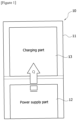
- Figure 1 schematically illustrates a configuration diagram of a conventional jig formation device.
- the formation process is a process of activating battery cells by repeatedly charging and discharging the battery cells, and removing gas. Upon the formation process of such battery cells, a lot of heat is generated, and in the case of a high-capacity battery cell, the calorific value is further increased.
- the conventional jig formation device (10) for performing the formation process comprises a device frame (11), a charging part (13), and a power supply part (12).
- the device frame (11) is a frame supporting the charging part (13) and the power supply part (12), respectively.
- the charging part (13) is provided to perform an activation process of a battery cell. In the activation process, the battery cell is charged and discharged through the charging part.
- the charging part (13) receives power from the power supply part (12).
- the power supply part (12) is installed below the charging part (13).
- the supply current specification of the power supply part increases.
- the size and calorific value of the power supply part increase together.
- the present invention is intended to provide a charge-and-discharge test apparatus capable of effectively cooling a power supply part supplying power to a charging part during a battery cell activation process, and a control method thereof.
- the present invention is intended to provide a charge-and-discharge test apparatus having a charging part and a power supply part mounted on a separate space in a frame part, and capable of supplying cooling air to a frame passage located between the charging part and the power supply part, and a control method thereof.
- the present invention is intended to provide a charge-and-discharge test apparatus capable of blocking heat generated from a power supply part from being transferred to a charging part, and a control method thereof.
- the present invention is intended to provide a charge-and-discharge test apparatus capable of improving air conditioning efficiency in the apparatus during a battery activation process, and a control method thereof.
- a charge-and-discharge test apparatus which comprises a charging part for charging and discharging battery cells, a power supply part for applying power to the charging part, a frame part comprising a first installation space in which the power supply part is disposed, a second installation space in which the charging part is disposed, a frame passage located between the first installation space and the second installation space, a first partition wall partitioning the frame passage and the first installation space and having a first flow hole, and a second partition wall partitioning the frame passage and the second installation space and having a second flow hole, a cooling duct disposed in the frame passage and having a supply hole open to the frame passage, one or more duct air supply parts provided to supply cooling air to the cooling duct, a first blowing fan provided to introduce air in the frame passage into the first installation space through the first flow hole, and a second blowing fan provided to introduce air in the second installation space into the frame passage through the second flow hole.
- the frame part has a first discharge hole for discharging air in the first installation space to the outside, which may be provided such that the cooling air introduced into the frame passage through the cooling duct is introduced into the first installation space, and then discharged to the outside of the frame part through the first discharge hole.
- the air introduced into the frame passage from the second installation space through the second flow hole is introduced into the first installation space together with the cooling air supplied from the cooling duct, and then discharged to the outside of the frame part through the first discharge hole.
- the charge-and-discharge test apparatus may comprise a first duct air supply part connected to one end of the cooling duct and a second duct air supply part connected to the other end of the cooling duct.
- the first duct air supply part may comprise a first air supply duct connected to the cooling duct and a first air supply fan provided in the first air supply duct
- the second duct air supply part may comprise a second air supply duct connected to the cooling duct and a second air supply fan provided in the second air supply duct.
- the cooling air may be supplied to both sides of the cooling duct, respectively.
- first discharge hole may be positioned to face the first flow hole.
- the power supply part may be located between the first discharge hole and the first flow hole.
- first flow hole and the second flow hole may be provided to be positioned at different heights within the frame part.
- the supply hole of the cooling duct may be provided at a higher position than the first flow hole in the frame part.
- the charge-and-discharge test apparatus may comprise a control part provided to control the power supply part, the charging part, the duct air supply part, and the first and second blowing fans.
- control part may be provided such that when the power is applied to the charging part, it operates the duct air supply part to supply the cooling air to the cooling duct, and operates the first and second blowing fans, respectively.
- the charge-and-discharge test apparatus may comprise a power supply room surrounding the frame part and including a room air supply part and a room exhaust part.
- the air introduced into the power supply room through the room air supply part is introduced into the second installation space of the frame part.
- the air discharged into the power supply room through the first discharge hole of the frame part may be discharged to the outside of the power supply room by the room exhaust part of the power supply room.
- a method of controlling a charge-and-discharge test apparatus comprises steps of: applying power to a charging part; supplying cooling air to a cooling duct; operating a first blowing fan to supply cooling air in a frame passage into a first installation space; and operating a second blowing fan to discharge the air in the first installation space to the frame passage.
- the charge-and-discharge test apparatus and its control method related to one example of the present invention have the following effects.
- the charging part and the power supply part in a separate space within the frame part and supplying cooling air to the frame passage located between the charging part and the power supply part, it is possible to block heat generated in the power supply part from being transferred to the charging part.
- first, second, and the like are used for the purpose of distinguishing one component from another.
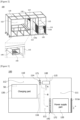
- Figure 2 is a perspective diagram showing main constitutions of a charge-and-discharge test apparatus (100) according to one example of the present invention
- Figure 3 is a front view showing main constitutions of a charge-and-discharge test apparatus according to one example of the present invention
- Figure 4 is a plan view showing main constitutions of a charge-and-discharge test apparatus according to one example of the present invention.
- the charge-and-discharge test apparatus (100) of the present invention comprises a charging part (130) for charging and discharging a battery cell (50), a power supply part (120) for applying power to the charging part (130), a frame part (110) in which the charging part (130) and the power supply part (120) are each installed, a cooling duct (140), one or more duct air supply parts (150, 160), a first blowing fan (172), and a second blowing fan (171).
- the charging part (130) is provided such that it performs the charge and discharge of the battery cell (50), and performs an activation process of the battery cell (50).
- the battery cell (50) may be a pouch-type battery cell that a stack cell, in which electrodes and separators are laminated, and an electrolyte are each accommodated in a pouch.
- the power supply part (120) applies power to the charging part (130).
- the charging part (130) and the power supply part (120) are known devices used in conventional jig formation devices, and detailed descriptions thereof will be omitted.
- the frame part (110) has a first installation space (111), a second installation space (112), and a frame passage (113).
- the frame part (110) comprises a first installation space (111) in which the power supply part (120) is disposed, a second installation space (112) in which the charging part (130) is disposed, and a frame passage (113) located between the first installation space (111) and the second installation space (112).
- the frame part (110) comprises a first partition wall (115) partitioning the frame passage (113) and the first installation space (111) and having a first flow hole (115a), and a second partition wall (116) partitioning the frame passage (113) and the second installation space (112) and having a second flow hole (114).
- the first flow hole (115a) and the second flow hole (114) may be configured in the form of a mesh through which air may flow.
- the internal space of the frame part (110) may be partitioned into the first installation space (111), the second installation space (112), and the frame passage (113) located between the first installation space (111) and the second installation space (112).
- the frame passage (113) physically separates the space in which the power supply part (120) and the charging part (130) are disposed, and provides a space capable of blocking heat generated from the power supply part (120) from being transferred to the charging part (130).
- the charge-and-discharge test apparatus (100) comprises a cooling duct (140) disposed in the frame passage (113) and having a supply hole (143) open to the frame passage (113), and one or more duct air supply parts (150, 160) provided to supply cooling air (A) to the cooling duct (140).
- the cooling air (A) When the cooling air (A) is supplied to the cooling duct (140) through the duct air supply parts (150, 160), the cooling air (A) may be introduced to the frame passage (113) through the supply hole (143) of the cooling duct (140). In this structure, the cooling air (A) may be supplied into the frame passage (113) between the first installation space (111) and the second installation space (112).
- the charge-and-discharge test apparatus (100) comprises a first blowing fan (172) provided to introduce air in the frame passage (113) into the first installation space (111) through the first flow hole (115a), and a second blowing fan (172) provided to introduce air in the second installation space (112) into the frame passage (113) through the second flow hole (114).
- first blowing fan (172) may be disposed to generate air flow in a direction from the frame passage (113) toward the first installation space (111). Furthermore, the first blowing fan (172) may be mounted on the first partition wall (115) and disposed adjacent to the first flow hole (115a).
- the second blowing fan (171) may be disposed to generate air flow in a direction from the second installation space (112) toward the frame passage (113).
- the second blowing fan (171) may be mounted on the second partition wall (114) and disposed adjacent to the second flow hole (114).
- the frame part (110) has a first discharge hole (111a) for discharging air in the first installation space (111) to the outside.
- the first discharge hole (111a) may be positioned to face the first flow hole (115a).
- the power supply part (120) may be positioned between the first discharge hole (111a) and the first flow hole (115a). In this structure, the air introduced into the first installation space (111) through the first flow hole (115a) may passes through the power supply part (120) to be discharged to the outside of the frame part (110) through the first discharge hole (111a).
- the cooling air (A) is supplied to the cooling duct (140) through the duct air supply parts (150, 160).
- cooling air (A) supplied to the frame passage (113) through the supply hole (143) of the cooling duct (140) is introduced into the first installation space (111) through the first flow hole (115a), and then discharged to the outside of the frame part (110) through the first discharge hole (111a).
- the air (B) introduced into the frame passage (113) from the second installation space (112) through the second flow hole (114a) is introduced into the first installation space (111) through the first flow hole (115a) together with the cooling air (A) supplied from the cooling duct (140), and then discharged to the outside of the frame part through the first discharge hole (111a).
- the cooling air (A) introduced into the frame passage (113) flows into the first installation space (111) through the first flow hole (115a) and heat-exchanges in the power supply part (120), and the air (C) heat-exchanged with the power supply part (120) is discharged from the first installation space (111) to the outside of the frame part (110) through the first discharge hole (111a). That is, the air (C) heat-exchanged with the power supply part (120) is discharged to the outside of the frame part (110) without being transferred to the charging part (120).
- first flow hole (115a) and the second flow hole (114) may be positioned at different heights within the frame part (110).
- the second flow hole (114) may be provided at a higher position than the first flow hole (115a).
- the supply hole (143) of the cooling duct (140) may be provided at a higher position than the first flow hole (115a) within the frame part (120).
- the cooling air (A) introduced into the frame passage through the supply hole (143) may fall toward the first flow hole (115a) and then be supplied to the first installation space (111).
- the air (B) supplied to the frame passage from the second installation space (112) may fall toward the first flow hole (115a) together with the cooling air (A), and then be supplied to the first installation space (111).
- the charge-and-discharge test apparatus (100) may comprise a control part (190) provided to control the power supply part (120), the charging part (130), the duct air supply parts (150, 160), the first blowing fan (172), and the second blowing fan (171).
- control part (190) may be provided such that it operates the duct air supply parts (150, 160) to supply the cooling air (A) to the cooling duct (140), and operates the first and second blowing fans (172, 171), respectively.
- the charge-and-discharge test apparatus (100) may comprise a first duct air supply part (150) connected to one end (141) of the cooling duct (140) and a second duct air supply part (160) connected to the other end (143) of the cooling duct (140).
- the cooling air (A) may be supplied to both sides of the cooling duct (140), respectively.
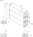
- Figures 5 to 7 are diagrams for explaining, in a state where a plurality of frame parts are stacked in a power supply room, flows of cooling air supplied to each frame part.
- the first duct air supply part (150) may comprise a first air supply duct (151) connected with the cooling duct (140) and a first air supply fan (152) provided in the first air supply duct (151).
- the second duct air supply part (160) may comprise a second air supply duct (161) connected with the cooling duct (140) and a second air supply fan (162) provided in the second air supply duct (161).
- the charge-and-discharge test apparatus (100) may comprise a power supply room (20) surrounding the frame part (110) and including a room air supply part (180) and a room exhaust part (185).
- the room air supply part (180) may be provided to supply air into the power supply room (20), and comprise one or more blowing fans
- the room exhaust part (185) may be provided to discharge air to the outside of the power supply room (20), and comprise one or more blowing fans.
- the air introduced into the power supply room (20) through the room air supply part (180) is introduced into the second installation space (112) of the frame part (110).
- the frame part (110) a part of the portion forming the second installation space (112) is opened into the power supply room (20).
- the air introduced into the second installation space (112) is heat-exchanged with the charging part (120), and the air (B) heat-exchanged with the charging part (120) flows into the frame passage (113) by the second blowing fan (172).
- the cooling air (A) supplied to the frame passage (113) through the cooling duct (140) flows into the first installation space (111), and then is discharged to the outside of the frame part (110) through the first discharge hole (111a).
- the air (C) discharged into the power supply room (20) through the first discharge hole (111a) of the frame part (110) may be discharged to the outside of the power supply room (20) by the room exhaust part (185) of the power supply room (20).
- the charge-and-discharge test apparatus (100) may comprise a plurality of frame parts (110) inside the power supply room (20). At this time, the charging part (130) and the power supply part (120) are disposed inside each frame part (110).
- the plurality of frame parts (110) may be stacked such that the respective frame passages (113) are arranged in a row along the height direction.
- the first and second air supply ducts (151, 161) are each connected to the cooling duct (140), and guide the cooling air (A) to the cooling duct (140).
- the first and second air supply fans (152, 162) are provided in the first and second air supply ducts (151, 161), respectively, which are blowing fans such that the cooling air (A) flows to the cooling duct (140) via the first and second air supply ducts (151, 162).
- the cooling air (A) is introduced into the cooling duct (140) through the first and second air supply ducts (151, 161), and the cooling air (A) flows from the cooling duct (140) to the first installation space (111) via the frame passage (113), and heat-exchanges with the power supply part (120) in the first installation space (111).
- the first air supply duct (151) and the second air supply duct (161) may be branched into several branches to be connected to the cooling duct (140) of the frame part (110).
- first and second air supply ducts (151, 161) may each comprise a plurality of air supply branch pipes (151a, 161a).
- branch air supply fans (153, 163) may be individually installed in each of the air supply branch pipes (151a, 161a). At this time, the respective branch air supply fans (153, 163) may be operated individually.
- the control method comprises steps of: applying power to a charging part; supplying cooling air to a cooling duct; operating a first blowing fan to supply cooling air in the frame passage into a first installation space; and operating a second blowing fan to discharge air in the first installation space to the frame passage.
- the charge-and-discharge test apparatus and its control method related to one example of the present invention by disposing the charging part and the power supply part in a separate space in the frame part, and supplying cooling air to the frame passage located between the charging part and the power supply part, it is possible to block heat generated form the power supply part from being transferred to the charging part.
Landscapes
- Engineering & Computer Science (AREA)
- Microelectronics & Electronic Packaging (AREA)
- Thermal Sciences (AREA)
- Physics & Mathematics (AREA)
- Chemical & Material Sciences (AREA)
- Electrochemistry (AREA)
- General Chemical & Material Sciences (AREA)
- Chemical Kinetics & Catalysis (AREA)
- Manufacturing & Machinery (AREA)
- Power Engineering (AREA)
- Secondary Cells (AREA)
- Cooling Or The Like Of Electrical Apparatus (AREA)
- Charge And Discharge Circuits For Batteries Or The Like (AREA)
Abstract
Description
- The present invention relates to a charge-and-discharge test apparatus, and a control method thereof, and relates to, in detail, a charge-and-discharge test apparatus capable of cooling a power supply part supplying power to a charging part performing a charge-and-discharge test of a battery cell during a battery cell activation process, and a control method thereof.
- The present application claims the benefit of priority based on
Korean Patent Application No. 10-2021-0175786 dated December 9, 2021 -
Figure 1 schematically illustrates a configuration diagram of a conventional jig formation device. - The formation process is a process of activating battery cells by repeatedly charging and discharging the battery cells, and removing gas. Upon the formation process of such battery cells, a lot of heat is generated, and in the case of a high-capacity battery cell, the calorific value is further increased.
- Referring to
Figure 1 , the conventional jig formation device (10) for performing the formation process comprises a device frame (11), a charging part (13), and a power supply part (12). - The device frame (11) is a frame supporting the charging part (13) and the power supply part (12), respectively. The charging part (13) is provided to perform an activation process of a battery cell. In the activation process, the battery cell is charged and discharged through the charging part. The charging part (13) receives power from the power supply part (12). In the conventional jig formation device, the power supply part (12) is installed below the charging part (13).
- As the battery cell is manufactured to have a high capacity, the supply current specification of the power supply part increases. In addition, when the capacity of the power supply part increases, the size and calorific value of the power supply part increase together.
- In the conventional jig formation device (10), there was a problem that in the battery cell activation process, the heat generated in the power supply part (12) is transferred to the charging part (13).
- The present invention is intended to provide a charge-and-discharge test apparatus capable of effectively cooling a power supply part supplying power to a charging part during a battery cell activation process, and a control method thereof.
- Also, the present invention is intended to provide a charge-and-discharge test apparatus having a charging part and a power supply part mounted on a separate space in a frame part, and capable of supplying cooling air to a frame passage located between the charging part and the power supply part, and a control method thereof.
- In addition, the present invention is intended to provide a charge-and-discharge test apparatus capable of blocking heat generated from a power supply part from being transferred to a charging part, and a control method thereof.
- Furthermore, the present invention is intended to provide a charge-and-discharge test apparatus capable of improving air conditioning efficiency in the apparatus during a battery activation process, and a control method thereof.
- In order to solve the above problems, according to one aspect of the present invention, a charge-and-discharge test apparatus is provided, which comprises a charging part for charging and discharging battery cells, a power supply part for applying power to the charging part, a frame part comprising a first installation space in which the power supply part is disposed, a second installation space in which the charging part is disposed, a frame passage located between the first installation space and the second installation space, a first partition wall partitioning the frame passage and the first installation space and having a first flow hole, and a second partition wall partitioning the frame passage and the second installation space and having a second flow hole, a cooling duct disposed in the frame passage and having a supply hole open to the frame passage, one or more duct air supply parts provided to supply cooling air to the cooling duct, a first blowing fan provided to introduce air in the frame passage into the first installation space through the first flow hole, and a second blowing fan provided to introduce air in the second installation space into the frame passage through the second flow hole.
- Also, the frame part has a first discharge hole for discharging air in the first installation space to the outside, which may be provided such that the cooling air introduced into the frame passage through the cooling duct is introduced into the first installation space, and then discharged to the outside of the frame part through the first discharge hole.
- In addition, it may be provided such that the air introduced into the frame passage from the second installation space through the second flow hole is introduced into the first installation space together with the cooling air supplied from the cooling duct, and then discharged to the outside of the frame part through the first discharge hole.
- Furthermore, a plurality of duct air supply parts may be provided. In this case, the charge-and-discharge test apparatus may comprise a first duct air supply part connected to one end of the cooling duct and a second duct air supply part connected to the other end of the cooling duct.
- Also, the first duct air supply part may comprise a first air supply duct connected to the cooling duct and a first air supply fan provided in the first air supply duct, and the second duct air supply part may comprise a second air supply duct connected to the cooling duct and a second air supply fan provided in the second air supply duct. In this structure, the cooling air may be supplied to both sides of the cooling duct, respectively.
- In addition, the first discharge hole may be positioned to face the first flow hole.
- Furthermore, the power supply part may be located between the first discharge hole and the first flow hole.
- Also, the first flow hole and the second flow hole may be provided to be positioned at different heights within the frame part.
- In addition, the supply hole of the cooling duct may be provided at a higher position than the first flow hole in the frame part.
- Furthermore, the charge-and-discharge test apparatus may comprise a control part provided to control the power supply part, the charging part, the duct air supply part, and the first and second blowing fans.
- Also, the control part may be provided such that when the power is applied to the charging part, it operates the duct air supply part to supply the cooling air to the cooling duct, and operates the first and second blowing fans, respectively.
- In addition, the charge-and-discharge test apparatus may comprise a power supply room surrounding the frame part and including a room air supply part and a room exhaust part.
- Furthermore, it may be provided such that the air introduced into the power supply room through the room air supply part is introduced into the second installation space of the frame part.
- In addition, the air discharged into the power supply room through the first discharge hole of the frame part may be discharged to the outside of the power supply room by the room exhaust part of the power supply room.
- According to another aspect of the present invention, as a control method of the charge-and-discharge test apparatus, a method of controlling a charge-and-discharge test apparatus is provided, which comprises steps of: applying power to a charging part; supplying cooling air to a cooling duct; operating a first blowing fan to supply cooling air in a frame passage into a first installation space; and operating a second blowing fan to discharge the air in the first installation space to the frame passage.
- As described above, the charge-and-discharge test apparatus and its control method related to one example of the present invention have the following effects.
- During the activation process of the battery cell, it is possible to effectively cool the power supply part supplying power to the charging part.
- Also, by disposing the charging part and the power supply part in a separate space within the frame part and supplying cooling air to the frame passage located between the charging part and the power supply part, it is possible to block heat generated in the power supply part from being transferred to the charging part.
- In addition, during the battery activation process, it is possible to improve air conditioning efficiency in the apparatus.
-
-
Figure 1 schematically illustrates a configuration diagram of a conventional jig formation device. -
Figure 2 is a perspective diagram showing main constitutions of a charge-and-discharge test apparatus according to one example of the present invention. -
Figure 3 is a front view showing main constitutions of a charge-and-discharge test apparatus according to one example of the present invention. -
Figure 4 is a plan view showing main constitutions of a charge-and-discharge test apparatus according to one example of the present invention. -
Figures 5 to 7 are diagrams for explaining, in a state where a plurality of frame parts are stacked in a power supply room, flows of cooling air supplied to each frame part. - Hereinafter, a charge-and-discharge test apparatus according to one example of the present invention, and a control method thereof will be described in detail with reference to the accompanying drawings.
- The accompanying drawings illustrate exemplary forms of the present invention, which are provided only to explain the present invention in detail, and the technical scope of the present invention is not limited thereto.
- In addition, regardless of reference numerals, the same or corresponding components are given with the same reference numerals, and redundant descriptions thereof will be omitted, and for convenience of description, the size and shape of each component member as shown may be exaggerated or reduced.
- The terms of first, second, and the like are used for the purpose of distinguishing one component from another.
-
Figure 2 is a perspective diagram showing main constitutions of a charge-and-discharge test apparatus (100) according to one example of the present invention,Figure 3 is a front view showing main constitutions of a charge-and-discharge test apparatus according to one example of the present invention, andFigure 4 is a plan view showing main constitutions of a charge-and-discharge test apparatus according to one example of the present invention. - The charge-and-discharge test apparatus (100) of the present invention comprises a charging part (130) for charging and discharging a battery cell (50), a power supply part (120) for applying power to the charging part (130), a frame part (110) in which the charging part (130) and the power supply part (120) are each installed, a cooling duct (140), one or more duct air supply parts (150, 160), a first blowing fan (172), and a second blowing fan (171).
- Here, the charging part (130) is provided such that it performs the charge and discharge of the battery cell (50), and performs an activation process of the battery cell (50). As one example, the battery cell (50) may be a pouch-type battery cell that a stack cell, in which electrodes and separators are laminated, and an electrolyte are each accommodated in a pouch.
- In addition, the power supply part (120) applies power to the charging part (130). The charging part (130) and the power supply part (120) are known devices used in conventional jig formation devices, and detailed descriptions thereof will be omitted.
- The frame part (110) has a first installation space (111), a second installation space (112), and a frame passage (113). Specifically, the frame part (110) comprises a first installation space (111) in which the power supply part (120) is disposed, a second installation space (112) in which the charging part (130) is disposed, and a frame passage (113) located between the first installation space (111) and the second installation space (112).
- In addition, the frame part (110) comprises a first partition wall (115) partitioning the frame passage (113) and the first installation space (111) and having a first flow hole (115a), and a second partition wall (116) partitioning the frame passage (113) and the second installation space (112) and having a second flow hole (114). The first flow hole (115a) and the second flow hole (114) may be configured in the form of a mesh through which air may flow.
- In this way, through the first partition wall (115) and the second partition wall (116), the internal space of the frame part (110) may be partitioned into the first installation space (111), the second installation space (112), and the frame passage (113) located between the first installation space (111) and the second installation space (112).
- The frame passage (113) physically separates the space in which the power supply part (120) and the charging part (130) are disposed, and provides a space capable of blocking heat generated from the power supply part (120) from being transferred to the charging part (130).
- The charge-and-discharge test apparatus (100) comprises a cooling duct (140) disposed in the frame passage (113) and having a supply hole (143) open to the frame passage (113), and one or more duct air supply parts (150, 160) provided to supply cooling air (A) to the cooling duct (140).
- When the cooling air (A) is supplied to the cooling duct (140) through the duct air supply parts (150, 160), the cooling air (A) may be introduced to the frame passage (113) through the supply hole (143) of the cooling duct (140). In this structure, the cooling air (A) may be supplied into the frame passage (113) between the first installation space (111) and the second installation space (112).
- Also, the charge-and-discharge test apparatus (100) comprises a first blowing fan (172) provided to introduce air in the frame passage (113) into the first installation space (111) through the first flow hole (115a), and a second blowing fan (172) provided to introduce air in the second installation space (112) into the frame passage (113) through the second flow hole (114).
- In addition, the first blowing fan (172) may be disposed to generate air flow in a direction from the frame passage (113) toward the first installation space (111). Furthermore, the first blowing fan (172) may be mounted on the first partition wall (115) and disposed adjacent to the first flow hole (115a).
- Also, the second blowing fan (171) may be disposed to generate air flow in a direction from the second installation space (112) toward the frame passage (113). In addition, the second blowing fan (171) may be mounted on the second partition wall (114) and disposed adjacent to the second flow hole (114).
- Also, the frame part (110) has a first discharge hole (111a) for discharging air in the first installation space (111) to the outside. In addition, the first discharge hole (111a) may be positioned to face the first flow hole (115a). Furthermore, the power supply part (120) may be positioned between the first discharge hole (111a) and the first flow hole (115a). In this structure, the air introduced into the first installation space (111) through the first flow hole (115a) may passe through the power supply part (120) to be discharged to the outside of the frame part (110) through the first discharge hole (111a).
- Upon operation of the duct air supply parts (150, 160), the cooling air (A) is supplied to the cooling duct (140) through the duct air supply parts (150, 160).
- It may be provided such that the cooling air (A) supplied to the frame passage (113) through the supply hole (143) of the cooling duct (140) is introduced into the first installation space (111) through the first flow hole (115a), and then discharged to the outside of the frame part (110) through the first discharge hole (111a).
- In addition, it may be provided such that the air (B) introduced into the frame passage (113) from the second installation space (112) through the second flow hole (114a) is introduced into the first installation space (111) through the first flow hole (115a) together with the cooling air (A) supplied from the cooling duct (140), and then discharged to the outside of the frame part through the first discharge hole (111a).
- The cooling air (A) introduced into the frame passage (113) flows into the first installation space (111) through the first flow hole (115a) and heat-exchanges in the power supply part (120), and the air (C) heat-exchanged with the power supply part (120) is discharged from the first installation space (111) to the outside of the frame part (110) through the first discharge hole (111a). That is, the air (C) heat-exchanged with the power supply part (120) is discharged to the outside of the frame part (110) without being transferred to the charging part (120).
- Also, the first flow hole (115a) and the second flow hole (114) may be positioned at different heights within the frame part (110). The second flow hole (114) may be provided at a higher position than the first flow hole (115a). In addition, the supply hole (143) of the cooling duct (140) may be provided at a higher position than the first flow hole (115a) within the frame part (120). In this structure, the cooling air (A) introduced into the frame passage through the supply hole (143) may fall toward the first flow hole (115a) and then be supplied to the first installation space (111). Furthermore, the air (B) supplied to the frame passage from the second installation space (112) may fall toward the first flow hole (115a) together with the cooling air (A), and then be supplied to the first installation space (111).
- In addition, the charge-and-discharge test apparatus (100) may comprise a control part (190) provided to control the power supply part (120), the charging part (130), the duct air supply parts (150, 160), the first blowing fan (172), and the second blowing fan (171).
- Furthermore, when the power is applied to the charging part (130), the control part (190) may be provided such that it operates the duct air supply parts (150, 160) to supply the cooling air (A) to the cooling duct (140), and operates the first and second blowing fans (172, 171), respectively.
- Referring to
Figure 4 , a plurality of duct air supply parts may be provided. In this case, the charge-and-discharge test apparatus (100) may comprise a first duct air supply part (150) connected to one end (141) of the cooling duct (140) and a second duct air supply part (160) connected to the other end (143) of the cooling duct (140). In this structure, the cooling air (A) may be supplied to both sides of the cooling duct (140), respectively. -
Figures 5 to 7 are diagrams for explaining, in a state where a plurality of frame parts are stacked in a power supply room, flows of cooling air supplied to each frame part. - Referring to
Figure 5 , the first duct air supply part (150) may comprise a first air supply duct (151) connected with the cooling duct (140) and a first air supply fan (152) provided in the first air supply duct (151). In addition, the second duct air supply part (160) may comprise a second air supply duct (161) connected with the cooling duct (140) and a second air supply fan (162) provided in the second air supply duct (161). - Referring to
Figure 7 , the charge-and-discharge test apparatus (100) may comprise a power supply room (20) surrounding the frame part (110) and including a room air supply part (180) and a room exhaust part (185). In addition, the room air supply part (180) may be provided to supply air into the power supply room (20), and comprise one or more blowing fans, and the room exhaust part (185) may be provided to discharge air to the outside of the power supply room (20), and comprise one or more blowing fans. - Also, it may be provided such that the air introduced into the power supply room (20) through the room air supply part (180) is introduced into the second installation space (112) of the frame part (110). In the frame part (110), a part of the portion forming the second installation space (112) is opened into the power supply room (20).
- In this structure, the air introduced into the second installation space (112) is heat-exchanged with the charging part (120), and the air (B) heat-exchanged with the charging part (120) flows into the frame passage (113) by the second blowing fan (172). In addition, through
Figure 3 , as described above, the cooling air (A) supplied to the frame passage (113) through the cooling duct (140) flows into the first installation space (111), and then is discharged to the outside of the frame part (110) through the first discharge hole (111a). - Also, referring to
Figure 7 , the air (C) discharged into the power supply room (20) through the first discharge hole (111a) of the frame part (110) may be discharged to the outside of the power supply room (20) by the room exhaust part (185) of the power supply room (20). - In addition, the charge-and-discharge test apparatus (100) may comprise a plurality of frame parts (110) inside the power supply room (20). At this time, the charging part (130) and the power supply part (120) are disposed inside each frame part (110).
- Referring to
Figures 5 and7 , the plurality of frame parts (110) may be stacked such that the respective frame passages (113) are arranged in a row along the height direction. - The first and second air supply ducts (151, 161) are each connected to the cooling duct (140), and guide the cooling air (A) to the cooling duct (140). In addition, the first and second air supply fans (152, 162) are provided in the first and second air supply ducts (151, 161), respectively, which are blowing fans such that the cooling air (A) flows to the cooling duct (140) via the first and second air supply ducts (151, 162).
- Upon operation of the first air supply fan (152) and the second air supply fan (162), the cooling air (A) is introduced into the cooling duct (140) through the first and second air supply ducts (151, 161), and the cooling air (A) flows from the cooling duct (140) to the first installation space (111) via the frame passage (113), and heat-exchanges with the power supply part (120) in the first installation space (111).
- Referring to
Figures 5 and6 , when the plurality of frame parts (110) is stacked and assembled in the height direction, the first air supply duct (151) and the second air supply duct (161) may be branched into several branches to be connected to the cooling duct (140) of the frame part (110). - To this end, the first and second air supply ducts (151, 161) may each comprise a plurality of air supply branch pipes (151a, 161a). In addition, branch air supply fans (153, 163) may be individually installed in each of the air supply branch pipes (151a, 161a). At this time, the respective branch air supply fans (153, 163) may be operated individually.
- According to another example of the present invention, as a control method of the charge-and-discharge test apparatus (100), the control method comprises steps of: applying power to a charging part; supplying cooling air to a cooling duct; operating a first blowing fan to supply cooling air in the frame passage into a first installation space; and operating a second blowing fan to discharge air in the first installation space to the frame passage.
- The preferred examples of the present invention as described above have been disclosed for illustrative purposes, and those skilled in the art having ordinary knowledge of the present invention will be able to make various modifications, changes, and additions within the spirit and scope of the present invention, and such modifications and changes and additions are intended to fall within the scope of the following claims.
- As described above, according to the charge-and-discharge test apparatus and its control method related to one example of the present invention, by disposing the charging part and the power supply part in a separate space in the frame part, and supplying cooling air to the frame passage located between the charging part and the power supply part, it is possible to block heat generated form the power supply part from being transferred to the charging part.
Claims (13)
- A charge-and-discharge test apparatus comprising:a charging part for charging and discharging battery cells;a power supply part for applying power to the charging part;a frame part comprising a first installation space in which the power supply part is disposed, a second installation space in which the charging part is disposed, a frame passage located between the first installation space and the second installation space, a first partition wall partitioning the frame passage and the first installation space and having a first flow hole, and a second partition wall partitioning the frame passage and the second installation space and having a second flow hole;a cooling duct disposed in the frame passage and having a supply hole open to the frame passage;one or more duct air supply parts provided to supply cooling air to the cooling duct;a first blowing fan provided to introduce air in the frame passage into the first installation space through the first flow hole; anda second blowing fan provided to introduce air in the second installation space into the frame passage through the second flow hole.
- The charge-and-discharge test apparatus according to claim 1, whereinthe frame part has a first discharge hole for discharging air in the first installation space to the outside, andthe cooling air introduced into the frame passage through the cooling duct is introduced into the first installation space, and then discharged to the outside of the frame part through the first discharge hole.
- The charge-and-discharge test apparatus according to claim 2, wherein
the air introduced into the frame passage from the second installation space through the second flow hole is introduced into the first installation space together with the cooling air supplied from the cooling duct, and then discharged to the outside of the frame part through the first discharge hole. - The charge-and-discharge test apparatus according to claim 1, whereinthe apparatus is provided with a plurality of duct air supply parts, andthe duct air supply part comprises a first duct air supply part connected to one end of the cooling duct and a second duct air supply part connected to the other end of the cooling duct, andthe first duct air supply part comprises a first air supply duct connected to the cooling duct; and a first air supply fan provided in the first air supply duct, andthe second duct air supply part comprises a second air supply duct connected to the cooling duct; and a second air supply fan provided in the second air supply duct.
- The charge-and-discharge test apparatus according to claim 2, wherein
the first discharge hole is positioned to face the first flow hole. - The charge-and-discharge test apparatus according to claim 5, wherein
the power supply part is located between the first discharge hole and the first flow hole. - The charge-and-discharge test apparatus according to claim 1, wherein
the first flow hole and the second flow hole are provided to be located at different heights in the frame part. - The charge-and-discharge test apparatus according to claim 1, wherein
the supply hole of the cooling duct is provided at a higher position than the first flow hole in the frame part. - The charge-and-discharge test apparatus according to claim 1,further comprising a control part provided to control the power supply part, the charging part, the duct air supply part, and the first and second blowing fans, whereinthe control part is provided such that when the power is applied to the charging part, it operates the duct air supply part to supply the cooling air to the cooling duct, and operates the first and second blowing fans, respectively.
- The charge-and-discharge test apparatus according to claim 2,
further comprising a power supply room surrounding the frame part and including a room air supply part and a room exhaust part. - The charge-and-discharge test apparatus according to claim 10,
provided such that the air introduced into the power supply room through the room air supply part is introduced into the second installation space of the frame part. - The charge-and-discharge test apparatus according to claim 11, wherein
the air discharged into the power supply room through the first discharge hole of the frame part is discharged to the outside of the power supply room by the room exhaust part of the power supply room. - A control method of the charge-and-discharge test apparatus according to any one of claims 1 to 12, wherein the control method of the charge-and-discharge test apparatus comprises steps of:applying power to a charging part;supplying cooling air to a cooling duct;operating a first blowing fan to supply cooling air in a frame passage into a first installation space; andoperating a second blowing fan to discharge the air in the first installation space to the frame passage.
Applications Claiming Priority (2)
| Application Number | Priority Date | Filing Date | Title |
|---|---|---|---|
| KR20210175786 | 2021-12-09 | ||
| PCT/KR2022/020001 WO2023106876A1 (en) | 2021-12-09 | 2022-12-09 | Charge/discharge test device and method for controlling same |
Publications (3)
| Publication Number | Publication Date |
|---|---|
| EP4319521A1 true EP4319521A1 (en) | 2024-02-07 |
| EP4319521A4 EP4319521A4 (en) | 2024-09-25 |
| EP4319521B1 EP4319521B1 (en) | 2025-07-16 |
Family
ID=86731002
Family Applications (1)
| Application Number | Title | Priority Date | Filing Date |
|---|---|---|---|
| EP22904705.5A Active EP4319521B1 (en) | 2021-12-09 | 2022-12-09 | Charge/discharge test device and method for controlling same |
Country Status (8)
| Country | Link |
|---|---|
| US (1) | US12446183B2 (en) |
| EP (1) | EP4319521B1 (en) |
| JP (1) | JP7631650B2 (en) |
| KR (1) | KR102857514B1 (en) |
| CN (1) | CN117242905A (en) |
| ES (1) | ES3049237T3 (en) |
| HU (1) | HUE073158T2 (en) |
| WO (1) | WO2023106876A1 (en) |
Family Cites Families (28)
| Publication number | Priority date | Publication date | Assignee | Title |
|---|---|---|---|---|
| JPH0779084A (en) * | 1993-07-16 | 1995-03-20 | Toshiba Corp | Electronic device cooling fin device |
| JP5034316B2 (en) | 2006-05-22 | 2012-09-26 | トヨタ自動車株式会社 | Power supply |
| JP2008269111A (en) * | 2007-04-17 | 2008-11-06 | Fujitsu Ltd | Electronic device storage box |
| US8216713B2 (en) | 2009-02-25 | 2012-07-10 | Sb Limotive Co., Ltd. | Battery housing formed with cooling passages and battery pack having the same |
| JP5450128B2 (en) * | 2010-01-28 | 2014-03-26 | 三洋電機株式会社 | Power supply device and vehicle equipped with the same |
| KR20100011256U (en) | 2010-10-31 | 2010-11-18 | 임재현 | Battery room air conditioner with refrigerant jacket |
| JP5738660B2 (en) * | 2011-04-18 | 2015-06-24 | エスペック株式会社 | Secondary battery charge / discharge evaluation system |
| US9048483B2 (en) * | 2012-07-16 | 2015-06-02 | Sanyo Electric Co., Ltd. | Power supply device, power-supply-device separator, and power supply-device-equipped vehicle and electric power storage |
| WO2014037988A1 (en) * | 2012-09-04 | 2014-03-13 | 富士通株式会社 | Temperature administration system |
| KR102119155B1 (en) * | 2013-01-30 | 2020-06-04 | 삼성에스디아이 주식회사 | Charge and discharge system |
| JP6124770B2 (en) * | 2013-10-30 | 2017-05-10 | エスペック株式会社 | Test apparatus and secondary battery evaluation method |
| US10263297B2 (en) * | 2014-04-22 | 2019-04-16 | The Boeing Company | Control system for a battery |
| JP6385766B2 (en) * | 2014-09-17 | 2018-09-05 | 株式会社東芝 | Vehicle storage battery device |
| US9559393B2 (en) * | 2014-09-30 | 2017-01-31 | Johnson Controls Technology Company | Battery module thermal management fluid guide assembly |
| JP5869093B1 (en) * | 2014-12-05 | 2016-02-24 | 株式会社日立パワーソリューションズ | control panel |
| JP2016145557A (en) * | 2015-02-09 | 2016-08-12 | アネスト岩田株式会社 | Package type fluid machinery |
| EP3259800B1 (en) | 2015-02-18 | 2022-12-07 | Shift Clean Solutions Ltd. | Lithium ion battery module with cooling system |
| JP2016207928A (en) * | 2015-04-27 | 2016-12-08 | ファナック株式会社 | Heat sink that cools multiple heat-generating components |
| CN105070950A (en) | 2015-09-07 | 2015-11-18 | 浙江杭可科技有限公司 | Formatting and grading equipment for soft package lithium-ion batteries |
| US10618692B2 (en) * | 2016-03-09 | 2020-04-14 | Makita Corporation | Stackable cases |
| JP6586698B2 (en) * | 2016-03-22 | 2019-10-09 | 福島工業株式会社 | Environmental performance evaluation equipment |
| KR102258818B1 (en) | 2017-01-09 | 2021-05-31 | 주식회사 엘지에너지솔루션 | Battery Pack having indirect cooling system |
| CN112514145B (en) * | 2018-07-30 | 2023-12-05 | 三洋电机株式会社 | Battery systems for vehicles and vehicles equipped with the battery systems |
| CN109546246A (en) | 2018-11-22 | 2019-03-29 | 浙江杭可科技股份有限公司 | Soft Roll power battery discharge energy recycles component capacitive equipment |
| KR102135773B1 (en) * | 2018-12-06 | 2020-07-20 | 효성중공업 주식회사 | Sub-module cooling device for power transmission system |
| KR102329209B1 (en) | 2019-12-20 | 2021-11-22 | 주식회사 성우하이텍 | Battery module assembly for electric vehicle |
| KR102289714B1 (en) * | 2021-01-15 | 2021-08-13 | 퍼스트 유한회사 | Storage box for battery cell |
| CN113410049B (en) * | 2021-06-24 | 2022-05-31 | 景亮 | Track traffic station centralized power supply system based on super capacitor |
-
2022
- 2022-12-09 CN CN202280032459.2A patent/CN117242905A/en active Pending
- 2022-12-09 KR KR1020220171051A patent/KR102857514B1/en active Active
- 2022-12-09 JP JP2023568645A patent/JP7631650B2/en active Active
- 2022-12-09 EP EP22904705.5A patent/EP4319521B1/en active Active
- 2022-12-09 HU HUE22904705A patent/HUE073158T2/en unknown
- 2022-12-09 WO PCT/KR2022/020001 patent/WO2023106876A1/en not_active Ceased
- 2022-12-09 US US18/290,429 patent/US12446183B2/en active Active
- 2022-12-09 ES ES22904705T patent/ES3049237T3/en active Active
Also Published As
| Publication number | Publication date |
|---|---|
| US12446183B2 (en) | 2025-10-14 |
| US20240260224A1 (en) | 2024-08-01 |
| KR102857514B1 (en) | 2025-09-12 |
| CN117242905A (en) | 2023-12-15 |
| EP4319521B1 (en) | 2025-07-16 |
| KR20230087408A (en) | 2023-06-16 |
| JP7631650B2 (en) | 2025-02-19 |
| EP4319521A4 (en) | 2024-09-25 |
| HUE073158T2 (en) | 2026-01-28 |
| WO2023106876A1 (en) | 2023-06-15 |
| ES3049237T3 (en) | 2025-12-15 |
| JP2024518452A (en) | 2024-05-01 |
Similar Documents
| Publication | Publication Date | Title |
|---|---|---|
| KR102142669B1 (en) | Air cooling type Battery Module having Guide vane | |
| US8748027B2 (en) | Middle or large-sized battery pack case providing improved distribution uniformity of coolant flux | |
| US10164305B2 (en) | Energy storage apparatus and method for cooling the energy storage apparatus | |
| JP5030500B2 (en) | Power supply | |
| US8211564B2 (en) | Middle or large-sized battery pack case providing improved distribution uniformity in coolant flux | |
| KR20210015328A (en) | Refrigerant immersion type battery cooling device | |
| JP2007042642A (en) | Battery module | |
| BRPI0516051B1 (en) | Cooling system for battery pack | |
| CN107431257B (en) | Battery pack | |
| US11075426B2 (en) | Battery pack | |
| EP4319521B1 (en) | Charge/discharge test device and method for controlling same | |
| US11621445B2 (en) | Charging/discharging device, having reduced temperature difference, for secondary battery formation process | |
| KR102034816B1 (en) | Battery Module Assembly | |
| EP4398450A1 (en) | Apparatus for charging and discharging | |
| KR20220046822A (en) | Battery charge and discharge system including cooling unit capable of distributing flow uniformly | |
| CN108140764A (en) | With the energy storage device for improving hot property | |
| KR102358605B1 (en) | Energy storage apparatus | |
| US20250023147A1 (en) | Secondary battery manufacturing system | |
| CN220086161U (en) | Container energy storage system | |
| KR20210063022A (en) | Battery pack cooling apparatus and operation method thereof | |
| US20230059324A1 (en) | Battery pack | |
| KR101252215B1 (en) | Battery Pack | |
| KR20250068894A (en) | Charging and discharging device | |
| JP2026504570A (en) | Charging and discharging device for secondary batteries | |
| CN119419431A (en) | Compact energy storage charging box assembly |
Legal Events
| Date | Code | Title | Description |
|---|---|---|---|
| STAA | Information on the status of an ep patent application or granted ep patent |
Free format text: STATUS: THE INTERNATIONAL PUBLICATION HAS BEEN MADE |
|
| PUAI | Public reference made under article 153(3) epc to a published international application that has entered the european phase |
Free format text: ORIGINAL CODE: 0009012 |
|
| STAA | Information on the status of an ep patent application or granted ep patent |
Free format text: STATUS: REQUEST FOR EXAMINATION WAS MADE |
|
| 17P | Request for examination filed |
Effective date: 20231102 |
|
| AK | Designated contracting states |
Kind code of ref document: A1 Designated state(s): AL AT BE BG CH CY CZ DE DK EE ES FI FR GB GR HR HU IE IS IT LI LT LU LV MC ME MK MT NL NO PL PT RO RS SE SI SK SM TR |
|
| A4 | Supplementary search report drawn up and despatched |
Effective date: 20240822 |
|
| RIC1 | Information provided on ipc code assigned before grant |
Ipc: G01R 31/36 20200101ALI20240817BHEP Ipc: H01M 10/667 20140101ALI20240817BHEP Ipc: H01M 10/6563 20140101ALI20240817BHEP Ipc: H02J 7/00 20060101ALI20240817BHEP Ipc: H01M 10/613 20140101ALI20240817BHEP Ipc: H01M 10/42 20060101ALI20240817BHEP Ipc: H01M 10/46 20060101ALI20240817BHEP Ipc: H05K 7/20 20060101AFI20240817BHEP |
|
| GRAP | Despatch of communication of intention to grant a patent |
Free format text: ORIGINAL CODE: EPIDOSNIGR1 |
|
| STAA | Information on the status of an ep patent application or granted ep patent |
Free format text: STATUS: GRANT OF PATENT IS INTENDED |
|
| GRAJ | Information related to disapproval of communication of intention to grant by the applicant or resumption of examination proceedings by the epo deleted |
Free format text: ORIGINAL CODE: EPIDOSDIGR1 |
|
| STAA | Information on the status of an ep patent application or granted ep patent |
Free format text: STATUS: REQUEST FOR EXAMINATION WAS MADE |
|
| DAV | Request for validation of the european patent (deleted) | ||
| DAX | Request for extension of the european patent (deleted) | ||
| GRAP | Despatch of communication of intention to grant a patent |
Free format text: ORIGINAL CODE: EPIDOSNIGR1 |
|
| STAA | Information on the status of an ep patent application or granted ep patent |
Free format text: STATUS: GRANT OF PATENT IS INTENDED |
|
| INTG | Intention to grant announced |
Effective date: 20250228 |
|
| INTC | Intention to grant announced (deleted) | ||
| INTG | Intention to grant announced |
Effective date: 20250324 |
|
| P01 | Opt-out of the competence of the unified patent court (upc) registered |
Free format text: CASE NUMBER: APP_14515/2025 Effective date: 20250325 |
|
| GRAS | Grant fee paid |
Free format text: ORIGINAL CODE: EPIDOSNIGR3 |
|
| GRAA | (expected) grant |
Free format text: ORIGINAL CODE: 0009210 |
|
| STAA | Information on the status of an ep patent application or granted ep patent |
Free format text: STATUS: THE PATENT HAS BEEN GRANTED |
|
| AK | Designated contracting states |
Kind code of ref document: B1 Designated state(s): AL AT BE BG CH CY CZ DE DK EE ES FI FR GB GR HR HU IE IS IT LI LT LU LV MC ME MK MT NL NO PL PT RO RS SE SI SK SM TR |
|
| REG | Reference to a national code |
Ref country code: GB Ref legal event code: FG4D |
|
| REG | Reference to a national code |
Ref country code: CH Ref legal event code: EP Ref country code: DE Ref legal event code: R096 Ref document number: 602022017848 Country of ref document: DE |
|
| REG | Reference to a national code |
Ref country code: IE Ref legal event code: FG4D |
|
| REG | Reference to a national code |
Ref country code: NL Ref legal event code: MP Effective date: 20250716 |
|
| PG25 | Lapsed in a contracting state [announced via postgrant information from national office to epo] |
Ref country code: PT Free format text: LAPSE BECAUSE OF FAILURE TO SUBMIT A TRANSLATION OF THE DESCRIPTION OR TO PAY THE FEE WITHIN THE PRESCRIBED TIME-LIMIT Effective date: 20251117 |
|
| PG25 | Lapsed in a contracting state [announced via postgrant information from national office to epo] |
Ref country code: NL Free format text: LAPSE BECAUSE OF FAILURE TO SUBMIT A TRANSLATION OF THE DESCRIPTION OR TO PAY THE FEE WITHIN THE PRESCRIBED TIME-LIMIT Effective date: 20250716 |
|
| REG | Reference to a national code |
Ref country code: ES Ref legal event code: FG2A Ref document number: 3049237 Country of ref document: ES Kind code of ref document: T3 Effective date: 20251215 Ref country code: AT Ref legal event code: MK05 Ref document number: 1815359 Country of ref document: AT Kind code of ref document: T Effective date: 20250716 |
|
| PG25 | Lapsed in a contracting state [announced via postgrant information from national office to epo] |
Ref country code: IS Free format text: LAPSE BECAUSE OF FAILURE TO SUBMIT A TRANSLATION OF THE DESCRIPTION OR TO PAY THE FEE WITHIN THE PRESCRIBED TIME-LIMIT Effective date: 20251116 |
|
| PGFP | Annual fee paid to national office [announced via postgrant information from national office to epo] |
Ref country code: DE Payment date: 20251120 Year of fee payment: 4 |
|
| PG25 | Lapsed in a contracting state [announced via postgrant information from national office to epo] |
Ref country code: NO Free format text: LAPSE BECAUSE OF FAILURE TO SUBMIT A TRANSLATION OF THE DESCRIPTION OR TO PAY THE FEE WITHIN THE PRESCRIBED TIME-LIMIT Effective date: 20251016 |
|
| REG | Reference to a national code |
Ref country code: LT Ref legal event code: MG9D |
|
| PG25 | Lapsed in a contracting state [announced via postgrant information from national office to epo] |
Ref country code: AT Free format text: LAPSE BECAUSE OF FAILURE TO SUBMIT A TRANSLATION OF THE DESCRIPTION OR TO PAY THE FEE WITHIN THE PRESCRIBED TIME-LIMIT Effective date: 20250716 |
|
| PG25 | Lapsed in a contracting state [announced via postgrant information from national office to epo] |
Ref country code: FI Free format text: LAPSE BECAUSE OF FAILURE TO SUBMIT A TRANSLATION OF THE DESCRIPTION OR TO PAY THE FEE WITHIN THE PRESCRIBED TIME-LIMIT Effective date: 20250716 |
|
| PG25 | Lapsed in a contracting state [announced via postgrant information from national office to epo] |
Ref country code: HR Free format text: LAPSE BECAUSE OF FAILURE TO SUBMIT A TRANSLATION OF THE DESCRIPTION OR TO PAY THE FEE WITHIN THE PRESCRIBED TIME-LIMIT Effective date: 20250716 |
|
| PGFP | Annual fee paid to national office [announced via postgrant information from national office to epo] |
Ref country code: HU Payment date: 20251216 Year of fee payment: 4 Ref country code: FR Payment date: 20251125 Year of fee payment: 4 |
|
| PG25 | Lapsed in a contracting state [announced via postgrant information from national office to epo] |
Ref country code: GR Free format text: LAPSE BECAUSE OF FAILURE TO SUBMIT A TRANSLATION OF THE DESCRIPTION OR TO PAY THE FEE WITHIN THE PRESCRIBED TIME-LIMIT Effective date: 20251017 |
|
| PGFP | Annual fee paid to national office [announced via postgrant information from national office to epo] |
Ref country code: BE Payment date: 20251120 Year of fee payment: 4 |
|
| PG25 | Lapsed in a contracting state [announced via postgrant information from national office to epo] |
Ref country code: SE Free format text: LAPSE BECAUSE OF FAILURE TO SUBMIT A TRANSLATION OF THE DESCRIPTION OR TO PAY THE FEE WITHIN THE PRESCRIBED TIME-LIMIT Effective date: 20250716 |
|
| PG25 | Lapsed in a contracting state [announced via postgrant information from national office to epo] |
Ref country code: LV Free format text: LAPSE BECAUSE OF FAILURE TO SUBMIT A TRANSLATION OF THE DESCRIPTION OR TO PAY THE FEE WITHIN THE PRESCRIBED TIME-LIMIT Effective date: 20250716 |
|
| PG25 | Lapsed in a contracting state [announced via postgrant information from national office to epo] |
Ref country code: BG Free format text: LAPSE BECAUSE OF FAILURE TO SUBMIT A TRANSLATION OF THE DESCRIPTION OR TO PAY THE FEE WITHIN THE PRESCRIBED TIME-LIMIT Effective date: 20250716 Ref country code: PL Free format text: LAPSE BECAUSE OF FAILURE TO SUBMIT A TRANSLATION OF THE DESCRIPTION OR TO PAY THE FEE WITHIN THE PRESCRIBED TIME-LIMIT Effective date: 20250716 |
|
| PG25 | Lapsed in a contracting state [announced via postgrant information from national office to epo] |
Ref country code: RS Free format text: LAPSE BECAUSE OF FAILURE TO SUBMIT A TRANSLATION OF THE DESCRIPTION OR TO PAY THE FEE WITHIN THE PRESCRIBED TIME-LIMIT Effective date: 20251016 |
|
| REG | Reference to a national code |
Ref country code: HU Ref legal event code: AG4A Ref document number: E073158 Country of ref document: HU |
|
| PG25 | Lapsed in a contracting state [announced via postgrant information from national office to epo] |
Ref country code: RO Free format text: LAPSE BECAUSE OF FAILURE TO SUBMIT A TRANSLATION OF THE DESCRIPTION OR TO PAY THE FEE WITHIN THE PRESCRIBED TIME-LIMIT Effective date: 20250716 |
|
| PG25 | Lapsed in a contracting state [announced via postgrant information from national office to epo] |
Ref country code: SM Free format text: LAPSE BECAUSE OF FAILURE TO SUBMIT A TRANSLATION OF THE DESCRIPTION OR TO PAY THE FEE WITHIN THE PRESCRIBED TIME-LIMIT Effective date: 20250716 |
|
| PGFP | Annual fee paid to national office [announced via postgrant information from national office to epo] |
Ref country code: ES Payment date: 20260122 Year of fee payment: 4 |
|
| PG25 | Lapsed in a contracting state [announced via postgrant information from national office to epo] |
Ref country code: DK Free format text: LAPSE BECAUSE OF FAILURE TO SUBMIT A TRANSLATION OF THE DESCRIPTION OR TO PAY THE FEE WITHIN THE PRESCRIBED TIME-LIMIT Effective date: 20250716 |
|
| PG25 | Lapsed in a contracting state [announced via postgrant information from national office to epo] |
Ref country code: IT Free format text: LAPSE BECAUSE OF FAILURE TO SUBMIT A TRANSLATION OF THE DESCRIPTION OR TO PAY THE FEE WITHIN THE PRESCRIBED TIME-LIMIT Effective date: 20250716 |
|
| PG25 | Lapsed in a contracting state [announced via postgrant information from national office to epo] |
Ref country code: CZ Free format text: LAPSE BECAUSE OF FAILURE TO SUBMIT A TRANSLATION OF THE DESCRIPTION OR TO PAY THE FEE WITHIN THE PRESCRIBED TIME-LIMIT Effective date: 20250716 |
|
| PG25 | Lapsed in a contracting state [announced via postgrant information from national office to epo] |
Ref country code: SK Free format text: LAPSE BECAUSE OF FAILURE TO SUBMIT A TRANSLATION OF THE DESCRIPTION OR TO PAY THE FEE WITHIN THE PRESCRIBED TIME-LIMIT Effective date: 20250716 Ref country code: EE Free format text: LAPSE BECAUSE OF FAILURE TO SUBMIT A TRANSLATION OF THE DESCRIPTION OR TO PAY THE FEE WITHIN THE PRESCRIBED TIME-LIMIT Effective date: 20250716 |