EP4318933A1 - Motor control device, motor, compressor, freezer, and vehicle - Google Patents
Motor control device, motor, compressor, freezer, and vehicle Download PDFInfo
- Publication number
- EP4318933A1 EP4318933A1 EP22780617.1A EP22780617A EP4318933A1 EP 4318933 A1 EP4318933 A1 EP 4318933A1 EP 22780617 A EP22780617 A EP 22780617A EP 4318933 A1 EP4318933 A1 EP 4318933A1
- Authority
- EP
- European Patent Office
- Prior art keywords
- motor
- harmonic component
- amplitude
- harmonic
- control apparatus
- Prior art date
- Legal status (The legal status is an assumption and is not a legal conclusion. Google has not performed a legal analysis and makes no representation as to the accuracy of the status listed.)
- Pending
Links
Images




Classifications
-
- H—ELECTRICITY
- H02—GENERATION; CONVERSION OR DISTRIBUTION OF ELECTRIC POWER
- H02P—CONTROL OR REGULATION OF ELECTRIC MOTORS, ELECTRIC GENERATORS OR DYNAMO-ELECTRIC CONVERTERS; CONTROLLING TRANSFORMERS, REACTORS OR CHOKE COILS
- H02P21/00—Arrangements or methods for the control of electric machines by vector control, e.g. by control of field orientation
- H02P21/05—Arrangements or methods for the control of electric machines by vector control, e.g. by control of field orientation specially adapted for damping motor oscillations, e.g. for reducing hunting
-
- B—PERFORMING OPERATIONS; TRANSPORTING
- B60—VEHICLES IN GENERAL
- B60L—PROPULSION OF ELECTRICALLY-PROPELLED VEHICLES; SUPPLYING ELECTRIC POWER FOR AUXILIARY EQUIPMENT OF ELECTRICALLY-PROPELLED VEHICLES; ELECTRODYNAMIC BRAKE SYSTEMS FOR VEHICLES IN GENERAL; MAGNETIC SUSPENSION OR LEVITATION FOR VEHICLES; MONITORING OPERATING VARIABLES OF ELECTRICALLY-PROPELLED VEHICLES; ELECTRIC SAFETY DEVICES FOR ELECTRICALLY-PROPELLED VEHICLES
- B60L15/00—Methods, circuits, or devices for controlling the traction-motor speed of electrically-propelled vehicles
- B60L15/02—Methods, circuits, or devices for controlling the traction-motor speed of electrically-propelled vehicles characterised by the form of the current used in the control circuit
- B60L15/025—Methods, circuits, or devices for controlling the traction-motor speed of electrically-propelled vehicles characterised by the form of the current used in the control circuit using field orientation; Vector control; Direct Torque Control [DTC]
-
- B—PERFORMING OPERATIONS; TRANSPORTING
- B60—VEHICLES IN GENERAL
- B60L—PROPULSION OF ELECTRICALLY-PROPELLED VEHICLES; SUPPLYING ELECTRIC POWER FOR AUXILIARY EQUIPMENT OF ELECTRICALLY-PROPELLED VEHICLES; ELECTRODYNAMIC BRAKE SYSTEMS FOR VEHICLES IN GENERAL; MAGNETIC SUSPENSION OR LEVITATION FOR VEHICLES; MONITORING OPERATING VARIABLES OF ELECTRICALLY-PROPELLED VEHICLES; ELECTRIC SAFETY DEVICES FOR ELECTRICALLY-PROPELLED VEHICLES
- B60L50/00—Electric propulsion with power supplied within the vehicle
- B60L50/50—Electric propulsion with power supplied within the vehicle using propulsion power supplied by batteries or fuel cells
- B60L50/51—Electric propulsion with power supplied within the vehicle using propulsion power supplied by batteries or fuel cells characterised by AC-motors
-
- F—MECHANICAL ENGINEERING; LIGHTING; HEATING; WEAPONS; BLASTING
- F25—REFRIGERATION OR COOLING; COMBINED HEATING AND REFRIGERATION SYSTEMS; HEAT PUMP SYSTEMS; MANUFACTURE OR STORAGE OF ICE; LIQUEFACTION SOLIDIFICATION OF GASES
- F25B—REFRIGERATION MACHINES, PLANTS OR SYSTEMS; COMBINED HEATING AND REFRIGERATION SYSTEMS; HEAT PUMP SYSTEMS
- F25B1/00—Compression machines, plants or systems with non-reversible cycle
- F25B1/04—Compression machines, plants or systems with non-reversible cycle with compressor of rotary type
-
- F—MECHANICAL ENGINEERING; LIGHTING; HEATING; WEAPONS; BLASTING
- F25—REFRIGERATION OR COOLING; COMBINED HEATING AND REFRIGERATION SYSTEMS; HEAT PUMP SYSTEMS; MANUFACTURE OR STORAGE OF ICE; LIQUEFACTION SOLIDIFICATION OF GASES
- F25B—REFRIGERATION MACHINES, PLANTS OR SYSTEMS; COMBINED HEATING AND REFRIGERATION SYSTEMS; HEAT PUMP SYSTEMS
- F25B13/00—Compression machines, plants or systems, with reversible cycle
-
- F—MECHANICAL ENGINEERING; LIGHTING; HEATING; WEAPONS; BLASTING
- F25—REFRIGERATION OR COOLING; COMBINED HEATING AND REFRIGERATION SYSTEMS; HEAT PUMP SYSTEMS; MANUFACTURE OR STORAGE OF ICE; LIQUEFACTION SOLIDIFICATION OF GASES
- F25B—REFRIGERATION MACHINES, PLANTS OR SYSTEMS; COMBINED HEATING AND REFRIGERATION SYSTEMS; HEAT PUMP SYSTEMS
- F25B31/00—Compressor arrangements
- F25B31/02—Compressor arrangements of motor-compressor units
-
- F—MECHANICAL ENGINEERING; LIGHTING; HEATING; WEAPONS; BLASTING
- F25—REFRIGERATION OR COOLING; COMBINED HEATING AND REFRIGERATION SYSTEMS; HEAT PUMP SYSTEMS; MANUFACTURE OR STORAGE OF ICE; LIQUEFACTION SOLIDIFICATION OF GASES
- F25B—REFRIGERATION MACHINES, PLANTS OR SYSTEMS; COMBINED HEATING AND REFRIGERATION SYSTEMS; HEAT PUMP SYSTEMS
- F25B43/00—Arrangements for separating or purifying gases or liquids; Arrangements for vaporising the residuum of liquid refrigerant, e.g. by heat
- F25B43/006—Accumulators
-
- F—MECHANICAL ENGINEERING; LIGHTING; HEATING; WEAPONS; BLASTING
- F25—REFRIGERATION OR COOLING; COMBINED HEATING AND REFRIGERATION SYSTEMS; HEAT PUMP SYSTEMS; MANUFACTURE OR STORAGE OF ICE; LIQUEFACTION SOLIDIFICATION OF GASES
- F25B—REFRIGERATION MACHINES, PLANTS OR SYSTEMS; COMBINED HEATING AND REFRIGERATION SYSTEMS; HEAT PUMP SYSTEMS
- F25B49/00—Arrangement or mounting of control or safety devices
- F25B49/02—Arrangement or mounting of control or safety devices for compression type machines, plants or systems
- F25B49/025—Motor control arrangements
-
- H—ELECTRICITY
- H02—GENERATION; CONVERSION OR DISTRIBUTION OF ELECTRIC POWER
- H02P—CONTROL OR REGULATION OF ELECTRIC MOTORS, ELECTRIC GENERATORS OR DYNAMO-ELECTRIC CONVERTERS; CONTROLLING TRANSFORMERS, REACTORS OR CHOKE COILS
- H02P21/00—Arrangements or methods for the control of electric machines by vector control, e.g. by control of field orientation
- H02P21/22—Current control, e.g. using a current control loop
-
- H—ELECTRICITY
- H02—GENERATION; CONVERSION OR DISTRIBUTION OF ELECTRIC POWER
- H02P—CONTROL OR REGULATION OF ELECTRIC MOTORS, ELECTRIC GENERATORS OR DYNAMO-ELECTRIC CONVERTERS; CONTROLLING TRANSFORMERS, REACTORS OR CHOKE COILS
- H02P27/00—Arrangements or methods for the control of AC motors characterised by the kind of supply voltage
- H02P27/04—Arrangements or methods for the control of AC motors characterised by the kind of supply voltage using variable-frequency supply voltage, e.g. inverter or converter supply voltage
- H02P27/06—Arrangements or methods for the control of AC motors characterised by the kind of supply voltage using variable-frequency supply voltage, e.g. inverter or converter supply voltage using DC to AC converters or inverters
- H02P27/08—Arrangements or methods for the control of AC motors characterised by the kind of supply voltage using variable-frequency supply voltage, e.g. inverter or converter supply voltage using DC to AC converters or inverters with pulse width modulation
-
- H—ELECTRICITY
- H02—GENERATION; CONVERSION OR DISTRIBUTION OF ELECTRIC POWER
- H02P—CONTROL OR REGULATION OF ELECTRIC MOTORS, ELECTRIC GENERATORS OR DYNAMO-ELECTRIC CONVERTERS; CONTROLLING TRANSFORMERS, REACTORS OR CHOKE COILS
- H02P27/00—Arrangements or methods for the control of AC motors characterised by the kind of supply voltage
- H02P27/04—Arrangements or methods for the control of AC motors characterised by the kind of supply voltage using variable-frequency supply voltage, e.g. inverter or converter supply voltage
- H02P27/06—Arrangements or methods for the control of AC motors characterised by the kind of supply voltage using variable-frequency supply voltage, e.g. inverter or converter supply voltage using DC to AC converters or inverters
- H02P27/08—Arrangements or methods for the control of AC motors characterised by the kind of supply voltage using variable-frequency supply voltage, e.g. inverter or converter supply voltage using DC to AC converters or inverters with pulse width modulation
- H02P27/12—Arrangements or methods for the control of AC motors characterised by the kind of supply voltage using variable-frequency supply voltage, e.g. inverter or converter supply voltage using DC to AC converters or inverters with pulse width modulation pulsing by guiding the flux vector, current vector or voltage vector on a circle or a closed curve, e.g. for direct torque control
-
- H—ELECTRICITY
- H02—GENERATION; CONVERSION OR DISTRIBUTION OF ELECTRIC POWER
- H02P—CONTROL OR REGULATION OF ELECTRIC MOTORS, ELECTRIC GENERATORS OR DYNAMO-ELECTRIC CONVERTERS; CONTROLLING TRANSFORMERS, REACTORS OR CHOKE COILS
- H02P29/00—Arrangements for regulating or controlling electric motors, appropriate for both AC and DC motors
- H02P29/50—Reduction of harmonics
-
- B—PERFORMING OPERATIONS; TRANSPORTING
- B60—VEHICLES IN GENERAL
- B60K—ARRANGEMENT OR MOUNTING OF PROPULSION UNITS OR OF TRANSMISSIONS IN VEHICLES; ARRANGEMENT OR MOUNTING OF PLURAL DIVERSE PRIME-MOVERS IN VEHICLES; AUXILIARY DRIVES FOR VEHICLES; INSTRUMENTATION OR DASHBOARDS FOR VEHICLES; ARRANGEMENTS IN CONNECTION WITH COOLING, AIR INTAKE, GAS EXHAUST OR FUEL SUPPLY OF PROPULSION UNITS IN VEHICLES
- B60K1/00—Arrangement or mounting of electrical propulsion units
-
- B—PERFORMING OPERATIONS; TRANSPORTING
- B60—VEHICLES IN GENERAL
- B60L—PROPULSION OF ELECTRICALLY-PROPELLED VEHICLES; SUPPLYING ELECTRIC POWER FOR AUXILIARY EQUIPMENT OF ELECTRICALLY-PROPELLED VEHICLES; ELECTRODYNAMIC BRAKE SYSTEMS FOR VEHICLES IN GENERAL; MAGNETIC SUSPENSION OR LEVITATION FOR VEHICLES; MONITORING OPERATING VARIABLES OF ELECTRICALLY-PROPELLED VEHICLES; ELECTRIC SAFETY DEVICES FOR ELECTRICALLY-PROPELLED VEHICLES
- B60L2240/00—Control parameters of input or output; Target parameters
- B60L2240/40—Drive Train control parameters
- B60L2240/42—Drive Train control parameters related to electric machines
- B60L2240/421—Speed
-
- B—PERFORMING OPERATIONS; TRANSPORTING
- B60—VEHICLES IN GENERAL
- B60L—PROPULSION OF ELECTRICALLY-PROPELLED VEHICLES; SUPPLYING ELECTRIC POWER FOR AUXILIARY EQUIPMENT OF ELECTRICALLY-PROPELLED VEHICLES; ELECTRODYNAMIC BRAKE SYSTEMS FOR VEHICLES IN GENERAL; MAGNETIC SUSPENSION OR LEVITATION FOR VEHICLES; MONITORING OPERATING VARIABLES OF ELECTRICALLY-PROPELLED VEHICLES; ELECTRIC SAFETY DEVICES FOR ELECTRICALLY-PROPELLED VEHICLES
- B60L2240/00—Control parameters of input or output; Target parameters
- B60L2240/40—Drive Train control parameters
- B60L2240/42—Drive Train control parameters related to electric machines
- B60L2240/427—Voltage
-
- B—PERFORMING OPERATIONS; TRANSPORTING
- B60—VEHICLES IN GENERAL
- B60L—PROPULSION OF ELECTRICALLY-PROPELLED VEHICLES; SUPPLYING ELECTRIC POWER FOR AUXILIARY EQUIPMENT OF ELECTRICALLY-PROPELLED VEHICLES; ELECTRODYNAMIC BRAKE SYSTEMS FOR VEHICLES IN GENERAL; MAGNETIC SUSPENSION OR LEVITATION FOR VEHICLES; MONITORING OPERATING VARIABLES OF ELECTRICALLY-PROPELLED VEHICLES; ELECTRIC SAFETY DEVICES FOR ELECTRICALLY-PROPELLED VEHICLES
- B60L2240/00—Control parameters of input or output; Target parameters
- B60L2240/40—Drive Train control parameters
- B60L2240/42—Drive Train control parameters related to electric machines
- B60L2240/429—Current
-
- B—PERFORMING OPERATIONS; TRANSPORTING
- B60—VEHICLES IN GENERAL
- B60L—PROPULSION OF ELECTRICALLY-PROPELLED VEHICLES; SUPPLYING ELECTRIC POWER FOR AUXILIARY EQUIPMENT OF ELECTRICALLY-PROPELLED VEHICLES; ELECTRODYNAMIC BRAKE SYSTEMS FOR VEHICLES IN GENERAL; MAGNETIC SUSPENSION OR LEVITATION FOR VEHICLES; MONITORING OPERATING VARIABLES OF ELECTRICALLY-PROPELLED VEHICLES; ELECTRIC SAFETY DEVICES FOR ELECTRICALLY-PROPELLED VEHICLES
- B60L2240/00—Control parameters of input or output; Target parameters
- B60L2240/40—Drive Train control parameters
- B60L2240/52—Drive Train control parameters related to converters
- B60L2240/526—Operating parameters
-
- B—PERFORMING OPERATIONS; TRANSPORTING
- B60—VEHICLES IN GENERAL
- B60L—PROPULSION OF ELECTRICALLY-PROPELLED VEHICLES; SUPPLYING ELECTRIC POWER FOR AUXILIARY EQUIPMENT OF ELECTRICALLY-PROPELLED VEHICLES; ELECTRODYNAMIC BRAKE SYSTEMS FOR VEHICLES IN GENERAL; MAGNETIC SUSPENSION OR LEVITATION FOR VEHICLES; MONITORING OPERATING VARIABLES OF ELECTRICALLY-PROPELLED VEHICLES; ELECTRIC SAFETY DEVICES FOR ELECTRICALLY-PROPELLED VEHICLES
- B60L2240/00—Control parameters of input or output; Target parameters
- B60L2240/40—Drive Train control parameters
- B60L2240/52—Drive Train control parameters related to converters
- B60L2240/529—Current
-
- B—PERFORMING OPERATIONS; TRANSPORTING
- B60—VEHICLES IN GENERAL
- B60L—PROPULSION OF ELECTRICALLY-PROPELLED VEHICLES; SUPPLYING ELECTRIC POWER FOR AUXILIARY EQUIPMENT OF ELECTRICALLY-PROPELLED VEHICLES; ELECTRODYNAMIC BRAKE SYSTEMS FOR VEHICLES IN GENERAL; MAGNETIC SUSPENSION OR LEVITATION FOR VEHICLES; MONITORING OPERATING VARIABLES OF ELECTRICALLY-PROPELLED VEHICLES; ELECTRIC SAFETY DEVICES FOR ELECTRICALLY-PROPELLED VEHICLES
- B60L2270/00—Problem solutions or means not otherwise provided for
- B60L2270/10—Emission reduction
- B60L2270/14—Emission reduction of noise
- B60L2270/147—Emission reduction of noise electro magnetic [EMI]
-
- F—MECHANICAL ENGINEERING; LIGHTING; HEATING; WEAPONS; BLASTING
- F25—REFRIGERATION OR COOLING; COMBINED HEATING AND REFRIGERATION SYSTEMS; HEAT PUMP SYSTEMS; MANUFACTURE OR STORAGE OF ICE; LIQUEFACTION SOLIDIFICATION OF GASES
- F25B—REFRIGERATION MACHINES, PLANTS OR SYSTEMS; COMBINED HEATING AND REFRIGERATION SYSTEMS; HEAT PUMP SYSTEMS
- F25B2600/00—Control issues
- F25B2600/02—Compressor control
- F25B2600/021—Inverters therefor
-
- F—MECHANICAL ENGINEERING; LIGHTING; HEATING; WEAPONS; BLASTING
- F25—REFRIGERATION OR COOLING; COMBINED HEATING AND REFRIGERATION SYSTEMS; HEAT PUMP SYSTEMS; MANUFACTURE OR STORAGE OF ICE; LIQUEFACTION SOLIDIFICATION OF GASES
- F25B—REFRIGERATION MACHINES, PLANTS OR SYSTEMS; COMBINED HEATING AND REFRIGERATION SYSTEMS; HEAT PUMP SYSTEMS
- F25B2600/00—Control issues
- F25B2600/02—Compressor control
- F25B2600/024—Compressor control by controlling the electric parameters, e.g. current or voltage
-
- F—MECHANICAL ENGINEERING; LIGHTING; HEATING; WEAPONS; BLASTING
- F25—REFRIGERATION OR COOLING; COMBINED HEATING AND REFRIGERATION SYSTEMS; HEAT PUMP SYSTEMS; MANUFACTURE OR STORAGE OF ICE; LIQUEFACTION SOLIDIFICATION OF GASES
- F25B—REFRIGERATION MACHINES, PLANTS OR SYSTEMS; COMBINED HEATING AND REFRIGERATION SYSTEMS; HEAT PUMP SYSTEMS
- F25B2700/00—Sensing or detecting of parameters; Sensors therefor
- F25B2700/15—Power, e.g. by voltage or current
- F25B2700/151—Power, e.g. by voltage or current of the compressor motor
-
- H—ELECTRICITY
- H02—GENERATION; CONVERSION OR DISTRIBUTION OF ELECTRIC POWER
- H02P—CONTROL OR REGULATION OF ELECTRIC MOTORS, ELECTRIC GENERATORS OR DYNAMO-ELECTRIC CONVERTERS; CONTROLLING TRANSFORMERS, REACTORS OR CHOKE COILS
- H02P2207/00—Indexing scheme relating to controlling arrangements characterised by the type of motor
- H02P2207/05—Synchronous machines, e.g. with permanent magnets or DC excitation
-
- H—ELECTRICITY
- H02—GENERATION; CONVERSION OR DISTRIBUTION OF ELECTRIC POWER
- H02P—CONTROL OR REGULATION OF ELECTRIC MOTORS, ELECTRIC GENERATORS OR DYNAMO-ELECTRIC CONVERTERS; CONTROLLING TRANSFORMERS, REACTORS OR CHOKE COILS
- H02P2207/00—Indexing scheme relating to controlling arrangements characterised by the type of motor
- H02P2207/05—Synchronous machines, e.g. with permanent magnets or DC excitation
- H02P2207/055—Surface mounted magnet motors
Definitions
- the present disclosure relates to a motor control apparatus, a motor, a compressor, a refrigeration apparatus and a vehicle.
- a known motor drive control apparatus is configured to convert a direct-current power supply having a constant direct-current voltage to a desirably selected pseudo three-phase alternating current by means of a three-phase bridge circuit, and drive a three-phase motor including a permanent magnet in the rotor.
- This motor drive control apparatus aims for reducing torque ripple on the motor by detecting an average value of the current at a direct-current portion of the three-phase bridge circuit, and controlling a desired current value of a rotation system such that a component having a frequency that is six times higher than the current frequency of the three-phase motor is reduced from the detected average value (for example, see PTL 1).
- a harmonic component is contained in a voltage induced in the motor, a harmonic component also occurs in a power that is input into the motor.
- a harmonic that is the same order as the harmonic component occurring in the power input into the motor may occur in a direct-current portion at an input side of an inverter circuit configured to supply the power to the motor.
- the present disclosure provides a motor control apparatus that can reduce a harmonic component that occurs in a power that is input into a motor, and a harmonic component that occurs in an electromagnetic exciting force of the motor, and a motor.
- the present disclosure provides a motor control apparatus configured to convert an input power supplied from a power supply to an output alternating-current power having a predetermined voltage and a predetermined frequency, the motor control apparatus including:
- the power supply may be an alternating-current power supply.
- a frequency of the first harmonic component and the second harmonic component may be a frequency that is a product of a fundamental frequency of a voltage input into the motor and a multiple of 6.
- the harmonic components (the harmonic components having the frequency that is the product of the fundamental frequency of the voltage input into the motor and a multiple of 6) that occur in the power input into the motor and in the electromagnetic exciting force of the motor.
- the motor control apparatus includes a control unit that is configured to perform the control.
- the control unit may superimpose an amount of compensation that changes synchronously with the rotation rate of the motor on an amount of operation of the motor control apparatus.
- the amount of operation may be at least one selected from a modulation rate of the inverter circuit, an amplitude of a voltage vector of the voltage input into the motor, a phase of the voltage vector, an amplitude of a current vector of a current input into the motor, and a phase of the current vector.
- control unit may detect a value correlating with the first harmonic component, and determine either or both of an amplitude and a phase of the amount of compensation based on a relationship between the first harmonic component and the second harmonic component.
- control unit may detect a value correlating with the second harmonic component, and determine either or both of the amplitude and the phase of the amount of compensation based on a relationship between the first harmonic component and the second harmonic component.
- the motor control apparatus may keep the relationship in the form of a table or a formula.
- control unit may detect a value correlating with the first harmonic component and a value correlating with the second harmonic value, and determine either or both of the amplitude and the phase of the amount of compensation.
- control unit may determine either or both of the amplitude and the phase of the amount of compensation based on the table or formula that is kept.
- a magnitude of variation of a component of energy stored in the motor having a same frequency as the first harmonic component may be lower than a magnitude of variation of a component of energy output through a torque of the motor having a same frequency as the second harmonic component.
- the present disclosure provides a motor controlled by a motor control apparatus configured to suppress a first harmonic component that occurs synchronously with a rotation rate of the motor in a power input into the motor, or a second harmonic component that occurs in an electromagnetic exciting force of the motor at a same frequency as the first harmonic component, wherein when the suppression is performed in the motor, a magnitude of variation of a component of energy stored in the motor having a same frequency as the first harmonic component is lower than a magnitude of variation of a component of energy output through a torque of the motor having a same frequency as the second harmonic component.
- the motor may be a surface magnet synchronous motor including a rotor and a stator.
- the rotor may include a rotor core and a plurality of magnets arranged in a circumferential direction of the rotor core.
- the motor may be an interior magnet synchronous motor including a rotor and a stator.
- the rotor may include a rotor core and a plurality of magnets.
- the rotor core may have a plurality of magnet insertion holes, and a magnetic resistance portion configured to suppress a main magnetic flux of the magnets.
- the present disclosure provides a compressor driven by the motor.
- the present disclosure provides a refrigeration apparatus including the compressor.
- a refrigeration apparatus including a compressor that is mounted with a motor in which a harmonic component that occurs in a power input into the motor and a harmonic component that occurs in an electromagnetic exciting force of the motor can be reduced.
- the present disclosure provides a vehicle mounted with the motor.
- a magnetomotive force and a gap permeance of a motor change in accordance with the rotation position of the motor
- an interlinkage flux changes synchronously with the rotation rate of the motor and a voltage induced in the motor contains harmonic components such as components having frequencies that are five times or seven times higher than the fundamental frequency of the voltage.
- harmonic components such as components having frequencies that are five times or seven times higher than the fundamental frequency of the voltage.
- the voltage induced in the motor contains such harmonic components
- a harmonic component having a frequency that is the product of the fundamental frequency of the induced voltage and a multiple of 6 occurs in a power input into the motor.
- a harmonic component in a power input into a motor likewise brings about occurrence of a harmonic, which has the same order as the harmonic component occurring in the power input into the motor, in the power at an input side of the inverter circuit. If this harmonic flows out into an alternating-current power supply that is present at the input side of the inverter circuit, a harmonic (power supply harmonic) having a frequency, which is the frequency of the power input into the motor ⁇ the frequency of the power supply voltage, is to be contained in the current at the power supply side.
- each power supply harmonic that occurs due to the harmonic component in the power input into the motor becomes lower than or equal to a regulatory power supply harmonic value.
- a power supply is a direct-current power supply such as a vehicle-mounted battery
- a harmonic current having the frequency of a power input into a motor occurs at the input side. Because the harmonic current accelerates deterioration of the battery, it is required to reduce the harmonic in the power input into the motor as it is required for an alternating-current power supply.
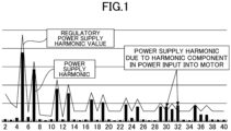
- FIG. 1 is a graph illustrating a harmonic that occurs at an input side of a power converter circuit, and the horizontal axis represents the order of the harmonic (i.e., multiples of the frequency of a power supply voltage).
- FIG. 1 illustrates that 30 th and 32 nd -order power supply harmonics are power supply harmonics due to a harmonic component that occurs in a power input into a motor, and that they exceed the regulatory power supply harmonic value. In this case, it is required to reduce the harmonic component in the power input into the motor such that the 30 th and 32 nd -order power supply harmonics become lower than or equal to the regulatory power supply harmonic value.
- the technique of PTL 1 aims for reducing torque ripple on a motor by detecting an average value of the current at a direct-current portion of a three-phase bridge circuit, and controlling the current such that a component having a frequency that is six times higher than the current frequency of a three-phase motor is reduced from the detected average value.
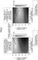
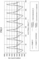
- FIG. 2 is an example of the result of analyzing the magnitudes of the harmonic (motor input power harmonic) that occurred in the power input into the motor and of the torque ripple on the motor, with respect to varying of the amplitude and the phase of a fifth-order harmonic (corresponding to a sixth-order harmonic occurring in the power input into the motor) that was superimposed on a phase current of the motor.
- the obtained result indicates that the amplitude and the phase of the waveform of a current for compensation at which the motor input power harmonic became minimum were different from the amplitude and the phase of the waveform of a current for compensation at which the torque ripple became minimum.
- the obtained result also indicates that a fifth-order harmonic-superimposed current waveform that made the magnitude of the motor input power harmonic minimum made the magnitude of the torque ripple slightly higher than was made by a sinusoidal current on which no fifth-order harmonic was superimposed.
- a technique according to the present disclosure reduces both a harmonic component (motor input power harmonic) that occurs in a power input into a motor and a harmonic component (electromagnetic exciting force harmonic) that occurs in an electromagnetic exciting force of the motor.
- the electromagnetic exciting force contains forces of a rotation direction component (circumferential direction component), a radial direction component, and an axial direction component.
- the torque ripple corresponds to a harmonic component in the rotation direction component of the electromagnetic exciting force.
- FIG. 4 is a diagram illustrating a motor control method, which is one of the techniques of the present disclosure for reducing a motor input power harmonic and an e electromagnetic exciting force harmonic.
- the motor control method reduces a motor input power harmonic and an electromagnetic exciting force harmonic by suppressing the amplitude of the motor input power harmonic to be lower than or equal to a predetermined value and suppressing the amplitude of the electromagnetic exciting force harmonic having the same frequency as the motor input power harmonic to be lower than the amplitude of the electromagnetic exciting force harmonic in a case of the amplitude of the motor input power harmonic being suppressed to a minimum.
- the motor input power harmonic is an example of the first harmonic component that occurs synchronously with the rotation rate of the motor in the power input into the motor.
- the electromagnetic exciting force harmonic having the same frequency as the motor input power harmonic is an example of the second harmonic component that occurs in the electromagnetic exciting force of the motor at the same frequency as the first harmonic component.
- Such a motor control method of the present disclosure can reduce a power supply harmonic to be lower than or equal to a regulatory power supply harmonic value and can reduce the amplitude of the electromagnetic exciting force harmonic to be lower than the amplitude of the electromagnetic exciting force harmonic in a case of the amplitude of the motor input power harmonic being suppressed to a minimum, by setting a predetermined value as a regulatory value for a harmonic component in a power input into the motor, the regulatory value being calculated from the regulatory power supply harmonic value.
- the local minimum value may be the lowest local minimum value among the plurality of local minimum values. Theoretically, a local minimum value is a value (zero) reached by complete suppression. However, there is a case where zero cannot be reached due to a control limit.
- FIG. 4 illustrates an example of a state in which the amplitude of the electromagnetic exciting force harmonic is suppressed to an amplitude value b2 that is lower than an amplitude value b1 assumed by the amplitude of the electromagnetic exciting force harmonic when the amplitude of the motor input power harmonic is suppressed to a minimum amplitude value a1.
- the amplitude of the motor input power harmonic is suppressed to an amplitude value a2 such that it does not exceed a reference value, and the amplitude of the electromagnetic exciting force harmonic is suppressed to the amplitude value b2.
- FIG. 5 is a diagram illustrating a motor structure, which is one of the techniques of the present disclosure for reducing a motor input power harmonic and an electromagnetic exciting force harmonic. As described above, it is difficult to reduce the amplitude of the electromagnetic exciting force harmonic merely by minimizing the amplitude of the motor input power harmonic.
- the motor according to the present disclosure has a motor structure that makes the condition under which the amplitude of the motor input power harmonic becomes minimum close to the condition under which the amplitude of the electromagnetic exciting force harmonic becomes minimum.
- a motor structure ensures reduction in the amplitude of the electromagnetic exciting force harmonic along with reduction in the amplitude of the motor input power harmonic.
- the motor according to the present disclosure has a motor structure that makes the phase difference between a waveform for compensation that minimizes the amplitude of the motor input power harmonic and a waveform for compensation that minimizes the amplitude of the electromagnetic exciting force harmonic less than 90°.
- This motor structure can reduce the amplitude of the electromagnetic exciting force harmonic from the amplitude value b1 to the amplitude value b3, when the amplitude of the motor input power harmonic is reduced to the amplitude value a1, as illustrated in FIG. 5 .
- the inductance of the motor is as low as possible, in order that the energy to be stored in a coil of the motor may be low. In order to make the inductance low, it is effective to employ a motor including a coil having a reduced number of turns, or a surface magnet synchronous motor.
- FIG. 6 is a block diagram illustrating a first configuration example of the motor control apparatus to which the techniques of the present disclosure are applied.
- the motor control apparatus 1A illustrated in FIG. 6 includes a converter circuit 2, a direct-current link section 3, an inverter circuit 4, and a control unit 5, and is configured to convert an input alternating-current power supplied from a three-phase alternating-current power supply 6 to an output alternating-current power having a predetermined voltage and a predetermined frequency, and supply the output alternating-current power to a motor 7.
- the motor 7 is, for example, a three-phase alternating-current motor.
- a specific example of the motor 7 is an electric motor configured to drive a compressor provided in a refrigerant circuit of an air conditioner.
- the motor 7 is, for example, a concentrated winding motor such as a four-pole six-slot type and a six-pole nine-slot type.
- a voltage induced in the motor 7 contains fifth-order and seventh-order components of the fundamental frequency as harmonic components.
- a high-order (e.g., sixth-order) harmonic component that is due to this motor voltage distortion may appear in a power input into the motor 7 and at an input side of the inverter circuit 4.
- This high-order harmonic component may appear in a power supply current i in of the alternating-current power supply 6, a direct-current link voltage v dc of the direct-current link section 3, a reactor voltage v L across both ends of a reactor 8, a reactor current i L flowing through the reactor 8, or a direct current i dc flowing through the direct-current link section 3.
- the converter circuit 2 is connected to the alternating-current power supply 6, and configured to convert an alternating current output by the alternating-current power supply 6 to a direct current.
- the converter circuit 2 is a diode bridge circuit in which a plurality of (in this example, six) diodes are connected in a bridge formation. These diodes are configured to rectify the full wave of the alternating-current voltage of the alternating-current power supply 6 to convert it to a direct-current voltage.
- the converter circuit 2 may be a voltage converter circuit of any other circuit configuration different from a diode bridge, so long as it is a circuit configured to supply the direct-current power obtained by conversion to the inverter circuit 4 via the direct-current link section 3.
- the direct-current link section 3 includes a capacitor 3a connected between the converter circuit 2 and the inverter circuit 4.
- the capacitor 3a is connected in parallel to the output portion of the converter circuit 2, and a direct-current voltage (direct-current link voltage v dc ) occurring across both ends of the capacitor 3a is input into an input node of the inverter circuit 4.
- the capacitor 3a will further be described below.
- the direct-current link section 3 includes a reactor 8 connected between the converter circuit 2 and the inverter circuit 4.
- the reactor 8 is inserted in series in a direct-current bus line between the output portion of the converter circuit 2 and the input portion of the inverter circuit 4.
- the inverter circuit 4 With its input node connected in parallel to the capacitor 3a of the direct-current link section 3, the inverter circuit 4 is configured to switch an output from the direct-current link section 3 to invert it to a three-phase alternating current, and supply it to the motor 7 connected to the inverter circuit 4.
- the inverter circuit 4 of the present embodiment is formed of a plurality of switching elements that are connected in a bridge formation.
- the inverter circuit 4 includes six switching elements, because the inverter circuit 4 outputs the three-phase alternating current to the motor 7.
- the inverter circuit 4 includes three switching legs connected in parallel to one another, and each switching leg includes two switching elements connected in series to each other.
- the middle point between an upper arm switching element and a lower arm switching element of each switching leg is connected to a coil of a corresponding phase of the motor 7.
- a freewheeling diode is connected in antiparallel to each switching element.
- the control unit 5 is configured to perform a control to suppress the amplitude of a first harmonic component that occurs synchronously with the rotation rate of the motor 7 in a power input into the motor 7 to be lower than or equal to a predetermined value, and to suppress the amplitude of a second harmonic component that occurs in an electromagnetic exciting force of the motor 7 at the same frequency as the first harmonic component to be lower than the amplitude of the second harmonic component in a case of the amplitude of the first harmonic component being suppressed to a minimum.
- the control unit 5 controls switching (ON-OFF operations) of the inverter circuit 4 such that the amplitude of the first harmonic component and the amplitude of the second harmonic component are suppressed in this manner.
- FIG. 7 is a diagram illustrating a second configuration example of the motor control apparatus to which the techniques of the present disclosure are applied.
- a motor control apparatus 1B illustrated in FIG. 7 includes a converter circuit 2, a direct-current link section 3, an inverter circuit 4, and a control unit 5, and is configured to convert an input alternating-current power supplied from a single-phase alternating-current power supply 6 to an output alternating-current power having a predetermined voltage and a predetermined frequency, and supply it to the motor 7.
- the converter circuit 2 is connected to the alternating-current power supply 6 via a reactor 8, and configured to rectify (convert) an alternating current output by the alternating-current power supply 6 to a direct current.
- the converter circuit 2 is, for example, a diode bridge circuit in which a plurality of (in this example, four) diodes are connected in a bridge formation. These diodes are configured to rectify the full wave of the alternating-current voltage of the alternating-current power supply 6 to convert it to a direct-current voltage.
- the converter circuit 2 may be a voltage converter circuit of any other circuit configuration different from a diode bridge, so long as it is a circuit configured to supply the direct-current power obtained by conversion to the inverter circuit 4 via the direct-current link section 3.
- the reactor 8 is connected between the alternating-current power supply 6 and the converter circuit 2, more specifically, inserted in series between the alternating current output side of the alternating-current power supply 6 and the alternating-current input side of the converter circuit 2.
- the capacitance of the capacitor 3a is set such that even though an output of the converter circuit 2 is almost unable to be smoothed, a ripple voltage (i.e., a voltage variation matching a switching frequency f c ) that is due to a switching operation of the inverter circuit 4 can be suppressed.
- the capacitor 3a is formed of a low-capacitance capacitor (e.g., a film capacitor) having a capacitance (e.g., approximately some tens of microfarads ( ⁇ F) through some hundreds of microfarads ( ⁇ F)) that is approximately one hundredths of the capacitance of a smoothing capacitor (e.g., an electrolytic capacitor) that is used for smoothing an output of the converter circuit 2 in a typical power converter apparatus or motor control apparatus.
- a low-capacitance capacitor e.g., a film capacitor
- a capacitance e.g., approximately some tens of microfarads ( ⁇ F) through some hundreds of microfarads ( ⁇ F)
- a smoothing capacitor e.g., an electrolytic capacitor
- the direct-current link voltage v dc contains a pulsating component having a frequency that is six times higher than the frequency of the power supply voltage v in of the three-phase alternating-current power supply 6 of FIG. 6 , or contains a pulsating component having a frequency that is twice higher than the frequency of the power supply voltage v in of the single-phase alternating-current power supply 6 of FIG. 7 .
- the reactor 8 and the capacitor 3a constitute an LC filter.
- the inductance of the reactor 8 and the capacitance of the capacitor 3a are set such that the resonance frequency f r of this LC filter is a frequency that is higher than or equal to an N-time multiple of the commercial frequency f in of the N-phase alternating-current power supply 6, and such that a ripple voltage due to a switching operation of the inverter circuit 4 will be decayed.
- N ⁇ f in ⁇ f r ⁇ f c / 4 f r 1 / 2 ⁇ ⁇ LC
- L represents the inductance of the reactor 8
- C represents the capacitance of the capacitor 3a.
- the motor control apparatus is a capacitor-less inverter (more specifically, an electrolytic capacitor-less inverter) in which the capacitance of the capacitor 3a of the direct-current link section 3 is such a low value as specified, there is a risk that a harmonic that is due to a distortion component (harmonic component) occurring in a power input into the motor 7 may flow out into the power supply side.
- the motor control apparatus is a matrix converter, there is likewise a risk that a harmonic due to a distortion component occurring in a power input into the motor may flow out into the power supply side.
- the control unit 5 illustrated in FIG. 6 or FIG. 7 is configured to perform a control to suppress the amplitude of a first harmonic component that occurs synchronously with the rotation rate of the motor 7 in a power input into the motor 7 to be lower than or equal to a predetermined value, and to suppress the amplitude of a second harmonic component that occurs in the electromagnetic exciting force of the motor 7 at the same frequency as the first harmonic component to be lower than the amplitude of the second harmonic component in a case of the amplitude of the first harmonic component being suppressed to a minimum.
- This control is also referred to as a harmonic suppressing control.
- vibrations due to a harmonic e.g., a power supply harmonic flowing out into the power supply side
- a harmonic e.g., a power supply harmonic flowing out into the power supply side
- control unit 5 superimposes an amount of compensation C that changes synchronously with the rotation rate of the motor 7 on an amount of operation D of the motor control apparatus illustrated in FIG. 6 or FIG. 7 .
- the control unit 5 superimposes an amount of compensation C that changes synchronously with the rotation rate of the motor 7 on an amount of operation D of the motor control apparatus illustrated in FIG. 6 or FIG. 7 .
- control unit 5 detects a value f correlating with the first harmonic component that occurs synchronously with the rotation rate of the motor 7 in a power input into the motor 7 by, for example, Fourier transform.
- a harmonic having the same order as the sixth-order harmonic component that occurs in the power input into the motor also occurs in a power at the input side of the inverter circuit.
- the value f correlating with the first harmonic component that occurs synchronously with the rotation rate of the motor 7 in the power input into the motor 7 is, for example, the amplitude of a harmonic component that occurs synchronously with the rotation rate of the motor 7 in the reactor voltage v L , the reactor current i L , the direct-current link voltage v dc , the direct current i dc , or the power supply current i in .
- a harmonic component that occurs synchronously with the rotation rate of the motor 7 in the reactor voltage v L , the reactor current i L , the direct-current link voltage v dc , or the direct current i dc has, for example, the same frequency as the first harmonic component.
- a harmonic component that occurs synchronously with the rotation rate of the motor 7 in the power supply current i in has, for example, a frequency, which is the frequency of the first harmonic component ⁇ the frequency of the power supply voltage.
- the control unit 5 detects the value f correlating with the first harmonic component that occurs synchronously with the rotation rate of the motor 7 in the power input into the motor 7, and derives either or both of an amplitude and a phase of an amount of correction C at which the detected value f becomes minimum.
- the control unit 5 corrects either or both of the amplitude and the phase of the amount of correction C at which the detected value f becomes minimum, such that the amplitude of the first harmonic component becomes lower than or equal to a reference value REF and the amplitude of the second harmonic component becomes lower, based on a relationship between the first harmonic component and the second harmonic component.
- the control unit 5 corrects the phase ⁇ c of the amount of compensation C, from ⁇ c1 to ⁇ c2 .
- data based on which either or both of the amplitude and the phase of the amount of correction C, at which the amplitude of the first harmonic component becomes lower than or equal to the reference value REF and the amplitude of the second harmonic component becomes lower, is or are determined is defined in the relationship between the first harmonic component and the second harmonic component. This relationship is kept in a memory in the form of a previously calculated table or formula.
- control unit 5 configured to perform the harmonic suppressing control.
- FIG. 9 is a block diagram illustrating a first configuration example of the control unit.
- the control unit 5A illustrated in FIG. 9 is an example of the control unit 5.
- the control unit 5A is configured to output a gate control signal G for switching ON or OFF each switching element in the inverter circuit 4 to the inverter circuit 4.
- the control unit 5A includes a motor control unit 11, a compensating unit 20, and a PWM calculating unit 12.
- each unit included in the control unit 5A is realized by, for example, a processor such as a Central Processing Unit (CPU) operating in accordance with a program that is readably stored in a memory.
- the function of each unit may also be realized by a Field Programmable Gate Array (FPGA) or an Application Specific Integrated Circuit (ASIC).
- FPGA Field Programmable Gate Array
- ASIC Application Specific Integrated Circuit
- the motor control unit 11 is configured to generate and output a phase (voltage phase ⁇ [°]) of an alternating-current voltage output by the inverter circuit 4 and a voltage control rate K of the inverter circuit 4.
- the voltage control rate is also referred to as a modulation rate.
- the superscript "*" as in " ⁇ *” represents a command value.
- the unit symbol in the brackets [] represents an example unit.
- the motor control unit 11 includes, for example, a velocity control unit 14, a current command generating unit 15, a current control unit 16, an adder 13, and a modulation rate calculating unit 17.
- the velocity control unit 14 is configured to generate a command torque T* [Nm] of the motor 7 such that the deviation between a command rotation rate ⁇ e * [rad/s] of the motor 7 and a detected rotation rate ⁇ e [rad/s] of the motor 7 becomes zero.
- the current command generating unit 15 is configured to generate an amplitude I a * [A] and a phase ⁇ * [°] of the current vector of a current input into the motor 7 based on the command torque T*.
- the current control unit 16 is configured to generate an amplitude V a * [V] and a phase ⁇ 0 * [°] of the voltage vector of a voltage (e.g., a line voltage) that is input into the motor 7 based on the amplitude I a * and the phase ⁇ * of the current vector, and a d-axis current i d and a q-axis current i q of the motor 7.
- ⁇ 0 * represents the zeroth-order component of the voltage phase ⁇ .
- the adder 13 is configured to generate a command value ⁇ * of the voltage phase ⁇ by adding an amount of compensation C to be generated by the compensating unit 20 to the phase ⁇ 0 * of the voltage vector. In this way, in the example illustrated in FIG.
- the modulation rate calculating unit 17 is configured to generate a command value K* of the voltage control rate K based on the amplitude V a * of the voltage vector and a detected value of the direct-current link voltage v dc .
- the detected rotation rate and the command rotation rate may be a mechanical angular velocity or an electrical angular velocity.
- the electrical angular velocity is obtained by multiplying the mechanical angular velocity by the number of pole pairs in the motor.
- the mechanical angular velocity represents the rotation rate of the motor in the form of an angle by which the motor rotates per unit time.
- the compensating unit 20 is configured to calculate an amount of compensation C based on which a harmonic in a power input into the motor 7 is offset.
- the compensating unit 20 includes, for example, a basic phase calculating unit 22, a phase-for-compensation calculating unit 21, an adder 24, a waveform generating unit 25, an amplitude calculating unit 26, and a multiplier 27.
- the basic phase calculating unit 22 is configured to detect the amplitude of a harmonic component that occurs synchronously with the rotation rate of the motor 7 in the reactor voltage v L by, for example, Fourier transform, as the value f correlating with a motor input power harmonic that occurs synchronously with the rotation rate of the motor 7 in the power input into the motor 7.
- the basic phase calculating unit 22 calculates a basic phase ⁇ vL_min at which the detected amplitude of the harmonic component in the reactor voltage v L is minimum, by using, for example, a hill-climbing method.
- the phase-for-compensation calculating unit 21 is configured to calculate a phase for compensation ⁇ com to be offset from the basic phase ⁇ vL_min , based on at least one selected from the detected rotation rate ⁇ e of the motor 7, the command rotation rate ⁇ e * of the motor 7, and an input power P in0 input into the motor 7.
- the input power P in0 represents, for example, an average value of the input power.
- the phase-for-compensation calculating unit 21 generates a phase for compensation ⁇ com corresponding to the detected rotation rate ⁇ e , based on such a correlation between the detected rotation rate ⁇ e and the phase for compensation ⁇ com as will make the amplitude of an electromagnetic exciting force harmonic, which occurs at the same frequency as the motor input power harmonic, lower than or equal to a predetermined threshold.
- the correlation that will make the amplitude of an electromagnetic exciting force harmonic, which occurs at the same frequency as the motor input power harmonic, lower than or equal to a predetermined threshold is, for example, a relational rule previously determined by, for example, a test, and is defined by, for example, a lookup table or an operation expression.
- the adder 24 is configured to calculate a corrected phase ⁇ ⁇ by adding the phase for compensation ⁇ com to the basic phase ⁇ vL_min .
- the waveform generating unit 25 is configured to generate a periodic waveform cos(6 ⁇ e + ⁇ ⁇ ) by adding the corrected phase ⁇ ⁇ to a rotation angle 6 ⁇ e , which is six times greater than the electrical angle of the motor 7.
- the amplitude calculating unit 26 is configured to calculate an amplitude ⁇ 6 of an amount of compensation C, based on at least one selected from the detected rotation rate ⁇ e of the motor 7, the command rotation rate ⁇ e * of the motor 7, and the input power P in0 in the motor 7. For example, the amplitude calculating unit 26 generates an amplitude ⁇ 6 corresponding to the detected rotation rate ⁇ e , based on such a correlation between the detected rotation rate ⁇ e and the amplitude ⁇ 6 as will make the amplitude of the motor input power harmonic and the amplitude of the electromagnetic exciting force harmonic, which occurs at the same frequency as the motor input power harmonic, lower than or equal to a predetermined threshold.
- the correlation that will make the amplitude of the motor input power harmonic and the amplitude of the electromagnetic exciting force harmonic, which occurs at the same frequency as the motor input power harmonic, lower than or equal to a predetermined threshold is, for example, a relational rule previously determined by, for example, a test, and is defined by, for example, a lookup table or an operation expression.
- a suitable amplitude ⁇ 6 can likewise be obtained using a correlation of this sort.
- the adder 13 adding the amount of compensation C generated by the compensating unit 20 to the phase ⁇ 0 * generated by the motor control unit 11, the command value ⁇ * of the voltage phase ⁇ is generated.
- the PWM calculating unit 12 is configured to generate a voltage command value for three phases including a u-phase, a v-phase, and a w-phase based on the command value K* of the voltage control rate K and the command value ⁇ * of the voltage phase ⁇ , using, for example, a polar coordinates transform, inverse Park transform, and space vector transform.
- the three-phase voltage command value is a Pulse Width Modulated (PWM) signal.
- PWM Pulse Width Modulated
- the PWM calculating unit 12 can control the magnitude of an alternating-current voltage to be output from the inverter circuit 4, by adjusting the amplitude of the three-phase voltage command value in accordance with the command value K* of the voltage control rate K.
- the PWM calculating unit 12 converts the three-phase voltage command value to a gate control signal G, and outputs it to the inverter circuit 4.
- control unit 5A detects a value correlating with a motor input power harmonic, and determines either or both of the amplitude and the phase of the amount of compensation C based on a relationship between the motor input power harmonic and an electromagnetic exciting force harmonic that occurs at the same frequency as the motor input power harmonic. Hence, it is possible to reduce the motor input power harmonic and the electromagnetic exciting force harmonic.
- the compensating unit 20 superimposes the amount of compensation C on the voltage phase ⁇ , which is an example of the amount of operation D.
- the compensating unit 20 may superimpose the amount of compensation C on at least one selected from the modulation rate K, the amplitude V a , the phase ⁇ , the amplitude I a , and the phase ⁇ .
- the basic phase calculating unit 22 detects the amplitude of a harmonic component that occurs synchronously with the rotation rate of the motor 7 in the reactor voltage v L by, for example, Fourier transform, as the value f correlating with a motor input power harmonic that occurs synchronously with the rotation rate of the motor 7 in a power input into the motor 7.
- the amplitude of a harmonic component occurring in the reactor voltage v L which is to be detected by the basic phase calculating unit 22, may be replaced with the value f described above regarding, for example, the direct-current link voltage v dc .
- the basic phase calculating unit 22 may detect a value g correlating with an electromagnetic exciting force harmonic that occurs at the same frequency as a motor input power harmonic, and calculate a basic phase ⁇ vL_min at which the amplitude of the detected value g is minimum, using, for example, a hill-climbing method.
- the basic phase calculating unit 22 may detect the value f correlating with a motor input power harmonic and the value g correlating with an electromagnetic exciting force harmonic that occurs at the same frequency as the motor input power harmonic, and calculate a basic phase ⁇ vL_min at which the amplitudes of the detected values f and g are lower than or equal to a predetermined value, using, for example, a hill-climbing method.
- the motor 7 according to the present disclosure is an electric motor controlled by the motor control apparatus configured to suppress a first harmonic component that occurs synchronously with the rotation rate of the motor 7 in a power input into the motor 7, or a second harmonic component that occurs in an electromagnetic exciting force of the motor 7 at the same frequency as the first harmonic component.
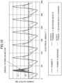
- a magnitude p1 of variation of a component of energy stored in the motor 7 having the same frequency as the first harmonic component is lower than a magnitude p2 of variation of a component of energy output through a torque of the motor 7 having the same frequency as the second harmonic component.
- FIG. 11 is a cross-sectional view illustrating a surface magnet synchronous motor 7A including a rotor 31 and a stator 32.
- the rotor 31 includes a rotor core 33, and a plurality of magnets 34 arranged in the circumferential direction of the rotor core 33.
- the stator 32 includes a stator core 37 and a coil 38.
- the stator core 37 includes a back yoke portion 39 and a plurality of teeth portions 40.
- the back yoke portion 39 is a portion formed in a substantially cylindrical shape.
- the back yoke portion 39 is formed of a magnetic material (e.g., an electromagnetic steel sheet).
- the plurality of teeth portions 40 are portions projecting from the internal periphery of the back yoke portion 39 inward in the radial direction.
- the teeth portions 40 are formed integrally with the back yoke portion 39.
- the teeth portions 40 are formed of a magnetic material (e.g., an electromagnetic steel sheet).
- the coil 38 is wound around the plurality of teeth portions 40.
- the coil 38 is formed of a conductor (e.g., copper) coated with an insulation material.
- the coil 38 is wound around each of the teeth portions 40 in a concentrated winding manner.
- the coil 38 may be wound around the plurality of teeth portions 40 in a distributed winding manner.
- the inductance of the surface magnet synchronous motor 7A is lower, and energy to be stored in the coil 38 provided on the stator 32 of the motor 7A is hence lower and p1 indicated in FIG. 10 is lower. Therefore, an amount of compensation C that reduces the amplitude of a harmonic in a power input into the motor 7A and an amount of compensation C that reduces the amplitude of a harmonic in an electromagnetic exciting force are close to each other, and it is possible to reduce the amplitude of the harmonic in the electromagnetic exciting force only by superimposing the amount of compensation C that reduces the amplitude of the harmonic in the power input into the motor 7A.
- FIG. 12 is a cross-sectional view illustrating an interior magnet synchronous motor 7B including a rotor 31 and a stator 32.
- the rotor 31 includes a rotor core 33, and a plurality of magnets 34 embedded in holes 35 formed in the rotor core 33.
- the holes 35 are slot-shaped voids.
- the rotor core 33 includes a magnetic resistance portions 36 provided to suppress a main magnetic flux of the magnets 34.
- the inductance of the motor 7B provided with the magnetic resistance portions 36 is lower, and energy to be stored in the coil 38 provided on the stator 32 of the motor 7B is hence lower and p1 indicated in FIG. 10 is lower.
- an amount of compensation C that reduces the amplitude of a harmonic in a power input into the motor 7B and an amount of compensation C that reduces the amplitude of a harmonic in an electromagnetic exciting force are close to each other, and it is possible to reduce the amplitude of the harmonic in the electromagnetic exciting force only by superimposing the amount of compensation C that reduces the amplitude of the harmonic in the power input into the motor 7B.
- the magnetic resistance portions 36 are, for example, cavities provided in the rotor core 33.
- the magnetic permeability through air existing in the cavities is lower than the magnetic permeability through the material (e.g., an electromagnetic steel sheet or a powder magnetic core) of the rotor core 33. Therefore, the magnetic resistance portions 36 suppress the main magnetic flux of the magnets 34.
- At least some of the magnetic resistance portions 36 may be replaced with a member (e.g., a nonmagnetic member) having a magnetic permeability lower than that of the material of the rotor core 33.
- the main magnetic flux of the magnets 34 can likewise be suppressed as can be suppressed by the air existing in the cavities.
- FIG. 13 is a diagram illustrating an example of a motor controlled by a motor control apparatus according to an embodiment or a refrigeration apparatus including a compressor driven by a motor according to an embodiment.
- FIG. 13 is a diagram illustrating an example of a refrigerant circuit of an air conditioner 101 in which a compressor 150 according to an embodiment is used.
- the air conditioner 101 is refrigeration cycle equipment (refrigeration apparatus) including a compressor 150.
- Examples of the air conditioner 101 in which the compressor 150 is used include "an air conditioner exclusively for an air-cooling operation", “an air conditioner exclusively for an air-warming operation", "a refrigeration apparatus exclusively for a refrigeration operation", and "an air conditioner switchable to either an air-cooling operation or an air-warming operation by use of a four-way valve". The following description will be given, using "an air conditioner switchable to either an air-cooling operation or an air-warming operation by use of a four-way valve".
- the air conditioner 101 includes an indoor unit 102 and an outdoor unit 103.
- the indoor unit 102 and the outdoor unit 103 are connected through a liquid refrigerant communicating pipe 104 and a gas refrigerant communicating pipe 105.
- the air conditioner 101 is a pair type including the indoor unit 102 and the outdoor unit 103 that are provided one-to-one.
- the air conditioner 101 is not limited to this type, and may be a multi type including a plurality of indoor units 102.
- devices such as an accumulator 115, a compressor 150, a four-way valve 116, an outdoor heat exchanger 117, an expansion valve 118, and an indoor heat exchanger 113 are connected through pipes, and constitute a refrigerant circuit 111.
- the refrigerant circuit 111 is filled with a refrigerant for performing vapor compression-type refrigeration cycles.
- the refrigerant is a mixture refrigerant containing 1,2-difluoroethylene.
- the refrigerant circuit 111 is also filled with a refrigerator oil together with the mixture refrigerant.
- the indoor heat exchanger 113 mounted in the indoor unit 102 is, for example, a cross fin-type fin-tube heat exchanger formed of a heat transfer tube and a plurality of heat transfer fins.
- a liquid side of the indoor heat exchanger 113 is connected to the liquid refrigerant communicating pipe 104, a gas side of the indoor heat exchanger 113 is connected to the gas refrigerant communicating pipe 105, and the indoor heat exchanger 113 functions as an evaporator of the refrigerant during a cooling operation.
- the outdoor unit 103 is mounted with the accumulator 115, the compressor 150, the outdoor heat exchanger 117, and the expansion valve 118.
- the outdoor heat exchanger 117 is, for example, a cross fin-type fin-tube heat exchanger formed of a heat transfer tube and a plurality of heat transfer fins.
- One side of the outdoor heat exchanger 117 is connected to a discharging pipe 124 through which a refrigerant discharged from the compressor 150 flows, and the other side of the outdoor heat exchanger 117 is connected to the liquid refrigerant communicating pipe 104.
- the outdoor heat exchanger 117 functions as a condenser of a gas refrigerant supplied from the compressor 150 through the discharging pipe 124.
- the expansion valve 118 is provided on a pipe that connects the outdoor heat exchanger 117 and the liquid refrigerant communicating pipe 104.
- the expansion valve 118 is an electric-operated valve, of which the opening degree can be adjusted in order to adjust the pressure and the flow rate of the refrigerant flowing through the pipe.
- the accumulator 115 is provided on a pipe that connects the gas refrigerant communicating pipe 105 and a suction pipe 123 of the compressor 150.
- the accumulator 115 is configured to separate the refrigerant that goes from the indoor heat exchanger 113 to the suction pipe 123 through the gas refrigerant communicating pipe 105 into a gas phase and a liquid phase in order to inhibit the liquid refrigerant from being supplied to the compressor 150.
- the gas-phase refrigerant that accumulates in an upper space of the accumulator 115 is supplied to the compressor 150.
- the four-way valve 116 includes first to fourth ports.
- the first port is connected to the discharging side of the compressor 150
- the second port is connected to the suction side of the compressor 150
- the third port is connected to the gas-side end portion of the outdoor heat exchanger 117
- the fourth port is connected to a gas-side shut-off valve Vg.
- the four-way valve 116 switches between a first state and a second state.
- the first port and the third port are connected, and the second port and the fourth port are connected.
- the four-way valve 116 is in the second state, the first port and the fourth port are connected, and the second port and the third port are connected.
- the compressor 150 is, for example, a scroll compressor.
- the compressor 150 includes a motor 170 controlled by a motor control apparatus 160, and a compression mechanism driven by the motor 170.
- the compressor 150 is configured to compress a refrigerant taken in through the suction pipe 123 in a compression chamber and discharge the refrigerant after being compressed from the discharging pipe 124 by being driven to rotate by the motor 170.
- the motor control apparatus 160 is configured to control the motor 170 by using an alternating-current power supplied from an alternating-current power supply.
- the motor control apparatus 160 corresponds to, for example, the motor control apparatuses 1A and 1B according to the embodiments described above.
- the motor 170 corresponds to, for example, the motor 7 controlled by, for example, the motor control apparatuses 1A and 1B according to the embodiments described above, or to, for example, the motors 7A and 7B according to the embodiments described above. Accordingly, the air conditioner 101 including the compressor 150 mounted with the motor 170 is provided, wherein a harmonic component that occurs in a power input into the motor 170 and a harmonic component that occurs in an electromagnetic exciting force of the motor 170 can be reduced.
- the refrigeration apparatus is not limited to the air conditioner, and may be, for example, oil cooling equipment.
- FIG. 14 is a view illustrating an example of a motor controlled by a motor control apparatus according to an embodiment or a vehicle mounted with a motor according to an embodiment.
- a motor 180 is configured to transmit a driving force to a driving shaft configured to drive a driving wheel of a vehicle 400.
- the vehicle 400 may be an Electric Vehicle (EV) using only the motor 180 as a power source, or may be a Hybrid Vehicle (HV) or a Plug-in Hybrid Electric Vehicle (PHEV) using both the motor 180 and, for example, an internal combustion engine as driving sources.
- EV Electric Vehicle
- HV Hybrid Vehicle
- PHEV Plug-in Hybrid Electric Vehicle
- the vehicle 400 includes a motor control apparatus 190, and a motor 180 controlled by the motor control apparatus 190.
- the illustrated mounting positions of the motor control apparatus 190 and the motor 180 are for expediency, and their mounting positions are not limited to the illustrated positions.
- the motor control apparatus 190 is configured to control the motor 180 using a direct-current power supplied from a direct-current power supply such as a vehicle-mounted battery.
- the motor control apparatus 190 corresponds to, for example, the motor control apparatuses 1A and 1B according to the embodiments described above.
- the motor 180 corresponds to, for example, the motor 7 controlled by, for example, the motor control apparatuses 1A and 1B according to the embodiments described above, or to, for example, the motors 7A and 7B according to the embodiments described above. Accordingly, the vehicle 400 mounted with the motor 180 is provided, wherein a harmonic component that occurs in a power input into the motor 180 and a harmonic component that occurs in an electromagnetic exciting force of the motor 180 can be reduced.
Landscapes
- Engineering & Computer Science (AREA)
- Power Engineering (AREA)
- Mechanical Engineering (AREA)
- General Engineering & Computer Science (AREA)
- Physics & Mathematics (AREA)
- Thermal Sciences (AREA)
- Transportation (AREA)
- Sustainable Energy (AREA)
- Sustainable Development (AREA)
- Life Sciences & Earth Sciences (AREA)
- Chemical & Material Sciences (AREA)
- Analytical Chemistry (AREA)
- Control Of Ac Motors In General (AREA)
Abstract
Description
- The present disclosure relates to a motor control apparatus, a motor, a compressor, a refrigeration apparatus and a vehicle.
- A known motor drive control apparatus is configured to convert a direct-current power supply having a constant direct-current voltage to a desirably selected pseudo three-phase alternating current by means of a three-phase bridge circuit, and drive a three-phase motor including a permanent magnet in the rotor. This motor drive control apparatus aims for reducing torque ripple on the motor by detecting an average value of the current at a direct-current portion of the three-phase bridge circuit, and controlling a desired current value of a rotation system such that a component having a frequency that is six times higher than the current frequency of the three-phase motor is reduced from the detected average value (for example, see PTL 1).
- [PTL 1]
Japanese Patent Application Publication No. 2010-88228 - If a harmonic component is contained in a voltage induced in the motor, a harmonic component also occurs in a power that is input into the motor. Hence, a harmonic that is the same order as the harmonic component occurring in the power input into the motor may occur in a direct-current portion at an input side of an inverter circuit configured to supply the power to the motor.
- However, even if a harmonic component that occurs in a power input into the motor is reduced, there may be a case where it is impossible to reduce a harmonic component, such as torque ripple, which occurs in an electromagnetic exciting force of the motor.
- The present disclosure provides a motor control apparatus that can reduce a harmonic component that occurs in a power that is input into a motor, and a harmonic component that occurs in an electromagnetic exciting force of the motor, and a motor.
- The present disclosure provides a motor control apparatus configured to convert an input power supplied from a power supply to an output alternating-current power having a predetermined voltage and a predetermined frequency, the motor control apparatus including:
- an inverter circuit configured to supply the output alternating-current power to a motor,
- wherein the motor control apparatus is configured to perform a control to suppress an amplitude of a first harmonic component that occurs synchronously with a rotation rate of the motor in a power input into the motor to be lower than or equal to a predetermined value and to suppress an amplitude of a second harmonic component that occurs in an electromagnetic exciting force of the motor at a same frequency as the first harmonic component to be lower than the amplitude of the second harmonic component in a case of the amplitude of the first harmonic component being suppressed to a minimum.
- Hence, it is possible to reduce the harmonic component that occurs in the power input into the motor and the harmonic component that occurs in the electromagnetic exciting force of the motor.
- In the motor control apparatus, the power supply may be an alternating-current power supply.
- Hence, it is possible to reduce a harmonic that flows out into the alternating-current power supply.
- In the motor control apparatus, a frequency of the first harmonic component and the second harmonic component may be a frequency that is a product of a fundamental frequency of a voltage input into the motor and a multiple of 6.
- Hence, it is possible to reduce the harmonic components (the harmonic components having the frequency that is the product of the fundamental frequency of the voltage input into the motor and a multiple of 6) that occur in the power input into the motor and in the electromagnetic exciting force of the motor.
- The motor control apparatus includes a control unit that is configured to perform the control.
- The control unit may superimpose an amount of compensation that changes synchronously with the rotation rate of the motor on an amount of operation of the motor control apparatus.
- Hence, it is possible to easily realize reduction in the harmonic component that occurs in the power input into the motor and the harmonic component that occurs in the electromagnetic exciting force of the motor.
- In the motor control apparatus, the amount of operation may be at least one selected from a modulation rate of the inverter circuit, an amplitude of a voltage vector of the voltage input into the motor, a phase of the voltage vector, an amplitude of a current vector of a current input into the motor, and a phase of the current vector.
- Hence, it is possible to more easily realize reduction in the harmonic component that occurs in the power input into the motor and the harmonic component that occurs in the electromagnetic exciting force of the motor.
- In the motor control apparatus, the control unit may detect a value correlating with the first harmonic component, and determine either or both of an amplitude and a phase of the amount of compensation based on a relationship between the first harmonic component and the second harmonic component.
- Hence, it is possible to easily realize reduction in the harmonic component that occurs in the power input into the motor and the harmonic component that occurs in the electromagnetic exciting force of the motor.
- In the motor control apparatus, the control unit may detect a value correlating with the second harmonic component, and determine either or both of the amplitude and the phase of the amount of compensation based on a relationship between the first harmonic component and the second harmonic component.
- Hence, it is possible to easily realize reduction in the harmonic component that occurs in the power input into the motor and the harmonic component that occurs in the electromagnetic exciting force of the motor.
- The motor control apparatus may keep the relationship in the form of a table or a formula.
- Hence, it is possible to easily realize reduction in the harmonic component that occurs in the power input into the motor and the harmonic component that occurs in the electromagnetic exciting force of the motor.
- In the motor control apparatus, the control unit may detect a value correlating with the first harmonic component and a value correlating with the second harmonic value, and determine either or both of the amplitude and the phase of the amount of compensation.
- Hence, it is possible to easily realize reduction in the harmonic component that occurs in the power input into the motor and the harmonic component that occurs in the electromagnetic exciting force of the motor.
- In the motor control apparatus, the control unit may determine either or both of the amplitude and the phase of the amount of compensation based on the table or formula that is kept.
- Hence, it is possible to easily realize reduction in the harmonic component that occurs in the power input into the motor and the harmonic component that occurs in the electromagnetic exciting force of the motor.
- In the motor control apparatus, when the control is performed, a magnitude of variation of a component of energy stored in the motor having a same frequency as the first harmonic component may be lower than a magnitude of variation of a component of energy output through a torque of the motor having a same frequency as the second harmonic component.
- Hence, it is possible to easily realize reduction in the harmonic component that occurs in the power input into the motor and the harmonic component that occurs in the electromagnetic exciting force of the motor.
- The present disclosure provides a motor controlled by a motor control apparatus configured to suppress a first harmonic component that occurs synchronously with a rotation rate of the motor in a power input into the motor, or a second harmonic component that occurs in an electromagnetic exciting force of the motor at a same frequency as the first harmonic component, wherein when the suppression is performed in the motor, a magnitude of variation of a component of energy stored in the motor having a same frequency as the first harmonic component is lower than a magnitude of variation of a component of energy output through a torque of the motor having a same frequency as the second harmonic component.
- Hence, it is possible to reduce the harmonic component that occurs in the power input into the motor and the harmonic component that occurs in the electromagnetic exciting force of the motor.
- The motor may be a surface magnet synchronous motor including a rotor and a stator.
- The rotor may include a rotor core and a plurality of magnets arranged in a circumferential direction of the rotor core.
- Hence, it is possible to reduce the harmonic component that occurs in the power input into the motor and the harmonic component that occurs in the electromagnetic exciting force of the motor.
- The motor may be an interior magnet synchronous motor including a rotor and a stator.
- The rotor may include a rotor core and a plurality of magnets.
- The rotor core may have a plurality of magnet insertion holes, and a magnetic resistance portion configured to suppress a main magnetic flux of the magnets.
- Hence, it is possible to reduce the harmonic component that occurs in the power input into the motor and the harmonic component that occurs in the electromagnetic exciting force of the motor.
- The present disclosure provides a compressor driven by the motor.
- Hence, it is possible to provide a compressor that is mounted with a motor in which a harmonic component that occurs in a power input into the motor and a harmonic component that occurs in an electromagnetic exciting force of the motor can be reduced.
- The present disclosure provides a refrigeration apparatus including the compressor.
- Hence, it is possible to provide a refrigeration apparatus including a compressor that is mounted with a motor in which a harmonic component that occurs in a power input into the motor and a harmonic component that occurs in an electromagnetic exciting force of the motor can be reduced.
- The present disclosure provides a vehicle mounted with the motor.
- Hence, it is possible to provide a vehicle mounted with a motor in which a harmonic component that occurs in a power input into the motor and a harmonic component that occurs in an electromagnetic exciting force of the motor can be reduced.
-
- [
FIG. 1] FIG. 1 is a graph illustrating a harmonic that occurs in a power supply current. - [
FIG. 2] FIG. 2 is an example of a result of analyzing the magnitudes of a harmonic (motor input power harmonic) that occurs in a power input into a motor and of torque ripple on the motor when the amplitude and the phase of a fifth-order harmonic to be superimposed on a phase current of the motor are varied. - [
FIG. 3] FIG. 3 is an example of a power and an output (= torque × rotation rate) of a motor derived by a magnetic field analysis with respect to an electrical angle of the motor. - [
FIG. 4] FIG. 4 is a diagram illustrating a motor control method, which is one of the techniques of the present disclosure for reducing a harmonic component that occurs in a power input into a motor and a harmonic component that occurs in an electromagnetic exciting force of the motor. - [
FIG. 5] FIG. 5 is a diagram illustrating a motor structure, which is one of the techniques of the present disclosure for reducing a harmonic component that occurs in a power input into a motor and a harmonic component that occurs in an electromagnetic exciting force of the motor. - [
FIG. 6] FIG. 6 is a diagram illustrating a first configuration example of a motor control apparatus. - [
FIG. 7] FIG. 7 is a diagram illustrating a second configuration example of a motor control apparatus. - [
FIG. 8] FIG. 8 is a diagram illustrating derivation of an amount of compensation to be superimposed on an amount of operation of a motor control apparatus. - [
FIG. 9] FIG. 9 is a block diagram illustrating a first configuration example of a control unit. - [
FIG. 10] FIG. 10 is an example of a power and an output (= torque × rotation rate) of a motor derived by a magnetic field analysis with respect to an electrical angle of the motor. - [
FIG. 11] FIG. 11 is a cross-sectional view illustrating a surface magnet synchronous motor including a rotor and a stator. - [
FIG. 12] FIG. 12 is a cross-sectional view illustrating an interior magnet synchronous motor including a rotor and a stator. - [
FIG. 13] FIG. 13 is a diagram illustrating an example of a motor controlled by a motor control apparatus according to an embodiment or a refrigeration apparatus including a compressor driven by a motor according to an embodiment. - [
FIG. 14] FIG. 14 is a view illustrating an example of a motor controlled by a motor control apparatus according to an embodiment or a vehicle mounted with a motor according to an embodiment. - Embodiments will be described below. First, a harmonic that occurs at an input side of an inverter circuit will be described.
- Because a magnetomotive force and a gap permeance of a motor change in accordance with the rotation position of the motor, there may be a case where an interlinkage flux changes synchronously with the rotation rate of the motor and a voltage induced in the motor contains harmonic components such as components having frequencies that are five times or seven times higher than the fundamental frequency of the voltage. When the voltage induced in the motor contains such harmonic components, there may be a case where a harmonic component having a frequency that is the product of the fundamental frequency of the induced voltage and a multiple of 6 occurs in a power input into the motor.
- For example, when a motor control apparatus such as a capacitor-less inverter that is free of an internal energy storage element is used, there may be a case where occurrence of a harmonic component in a power input into a motor likewise brings about occurrence of a harmonic, which has the same order as the harmonic component occurring in the power input into the motor, in the power at an input side of the inverter circuit. If this harmonic flows out into an alternating-current power supply that is present at the input side of the inverter circuit, a harmonic (power supply harmonic) having a frequency, which is the frequency of the power input into the motor ± the frequency of the power supply voltage, is to be contained in the current at the power supply side. Hence, it is required to reduce the harmonic component in the power input into the motor such that each power supply harmonic that occurs due to the harmonic component in the power input into the motor becomes lower than or equal to a regulatory power supply harmonic value. Also when a power supply is a direct-current power supply such as a vehicle-mounted battery, a harmonic current having the frequency of a power input into a motor occurs at the input side. Because the harmonic current accelerates deterioration of the battery, it is required to reduce the harmonic in the power input into the motor as it is required for an alternating-current power supply.
-
FIG. 1 is a graph illustrating a harmonic that occurs at an input side of a power converter circuit, and the horizontal axis represents the order of the harmonic (i.e., multiples of the frequency of a power supply voltage).FIG. 1 illustrates that 30th and 32nd-order power supply harmonics are power supply harmonics due to a harmonic component that occurs in a power input into a motor, and that they exceed the regulatory power supply harmonic value. In this case, it is required to reduce the harmonic component in the power input into the motor such that the 30th and 32nd-order power supply harmonics become lower than or equal to the regulatory power supply harmonic value. - Meanwhile, as described above, the technique of
PTL 1 aims for reducing torque ripple on a motor by detecting an average value of the current at a direct-current portion of a three-phase bridge circuit, and controlling the current such that a component having a frequency that is six times higher than the current frequency of a three-phase motor is reduced from the detected average value. - Here, a result illustrated in
FIG. 2 was obtained when examining by magnetic field analysis as to whether both a harmonic occurring in a power input into a motor and torque ripple on the motor are reduced, when superimposing a waveform for harmonic compensation on a current.FIG. 2 is an example of the result of analyzing the magnitudes of the harmonic (motor input power harmonic) that occurred in the power input into the motor and of the torque ripple on the motor, with respect to varying of the amplitude and the phase of a fifth-order harmonic (corresponding to a sixth-order harmonic occurring in the power input into the motor) that was superimposed on a phase current of the motor. - As illustrated in
FIG. 2 , the obtained result indicates that the amplitude and the phase of the waveform of a current for compensation at which the motor input power harmonic became minimum were different from the amplitude and the phase of the waveform of a current for compensation at which the torque ripple became minimum. The obtained result also indicates that a fifth-order harmonic-superimposed current waveform that made the magnitude of the motor input power harmonic minimum made the magnitude of the torque ripple slightly higher than was made by a sinusoidal current on which no fifth-order harmonic was superimposed. As clear from this, there is a case where it is impossible to reduce the torque ripple on the motor by superimposition of a waveform for harmonic compensation that reduces the motor input power harmonic. - Consideration will be given to this point. Provided that loss is ignored, it is considered that "power = torque × rotation rate" is satisfied in terms of an average power value. However, since the magnetic field analysis indicated that the waveform of the power supplied to the motor and the waveform of the output (= torque × rotation rate) of the motor did not match each other as illustrated in
FIG. 3 , it was found that "power = torque × rotation rate" is not satisfied in terms of an instantaneous power value. The reason for this is inferred to be instantaneous storage of energy in a coil of the motor. The energy instantaneously stored in a coil of the motor is referred to as stored energy of the motor. -
FIG. 3 is an example of the power and the output (= torque × rotation rate) of the motor derived by the magnetic field analysis with respect to an electrical angle of the motor. InFIG. 3 , loss is ignored. As illustrated inFIG. 3 , the waveform of the power supplied to the motor and the waveform of the output of the motor match each other in terms of the average power value, but does not match each other in terms of the instantaneous power value. Hence, it is safe to say that reduction in the torque ripple on the motor is not always ensured by mere minimization of a motor input power harmonic. - A technique according to the present disclosure reduces both a harmonic component (motor input power harmonic) that occurs in a power input into a motor and a harmonic component (electromagnetic exciting force harmonic) that occurs in an electromagnetic exciting force of the motor. The electromagnetic exciting force contains forces of a rotation direction component (circumferential direction component), a radial direction component, and an axial direction component. The torque ripple corresponds to a harmonic component in the rotation direction component of the electromagnetic exciting force.
-
FIG. 4 is a diagram illustrating a motor control method, which is one of the techniques of the present disclosure for reducing a motor input power harmonic and an e electromagnetic exciting force harmonic. - The motor control method according to the present disclosure reduces a motor input power harmonic and an electromagnetic exciting force harmonic by suppressing the amplitude of the motor input power harmonic to be lower than or equal to a predetermined value and suppressing the amplitude of the electromagnetic exciting force harmonic having the same frequency as the motor input power harmonic to be lower than the amplitude of the electromagnetic exciting force harmonic in a case of the amplitude of the motor input power harmonic being suppressed to a minimum. The motor input power harmonic is an example of the first harmonic component that occurs synchronously with the rotation rate of the motor in the power input into the motor. The electromagnetic exciting force harmonic having the same frequency as the motor input power harmonic is an example of the second harmonic component that occurs in the electromagnetic exciting force of the motor at the same frequency as the first harmonic component. Such a motor control method of the present disclosure can reduce a power supply harmonic to be lower than or equal to a regulatory power supply harmonic value and can reduce the amplitude of the electromagnetic exciting force harmonic to be lower than the amplitude of the electromagnetic exciting force harmonic in a case of the amplitude of the motor input power harmonic being suppressed to a minimum, by setting a predetermined value as a regulatory value for a harmonic component in a power input into the motor, the regulatory value being calculated from the regulatory power supply harmonic value.
- "When the amplitude of the first harmonic component (in this example, the motor input power harmonic) is suppressed to a minimum" means "when the amplitude of the first harmonic component is suppressed to a local minimum value by a motor control". When a plurality of local minimum values exist, the local minimum value may be the lowest local minimum value among the plurality of local minimum values. Theoretically, a local minimum value is a value (zero) reached by complete suppression. However, there is a case where zero cannot be reached due to a control limit.
FIG. 4 illustrates an example of a state in which the amplitude of the electromagnetic exciting force harmonic is suppressed to an amplitude value b2 that is lower than an amplitude value b1 assumed by the amplitude of the electromagnetic exciting force harmonic when the amplitude of the motor input power harmonic is suppressed to a minimum amplitude value a1. In the example illustrated inFIG. 4 , the amplitude of the motor input power harmonic is suppressed to an amplitude value a2 such that it does not exceed a reference value, and the amplitude of the electromagnetic exciting force harmonic is suppressed to the amplitude value b2. -
FIG. 5 is a diagram illustrating a motor structure, which is one of the techniques of the present disclosure for reducing a motor input power harmonic and an electromagnetic exciting force harmonic. As described above, it is difficult to reduce the amplitude of the electromagnetic exciting force harmonic merely by minimizing the amplitude of the motor input power harmonic. - The motor according to the present disclosure has a motor structure that makes the condition under which the amplitude of the motor input power harmonic becomes minimum close to the condition under which the amplitude of the electromagnetic exciting force harmonic becomes minimum. Such a motor structure ensures reduction in the amplitude of the electromagnetic exciting force harmonic along with reduction in the amplitude of the motor input power harmonic. For example, the motor according to the present disclosure has a motor structure that makes the phase difference between a waveform for compensation that minimizes the amplitude of the motor input power harmonic and a waveform for compensation that minimizes the amplitude of the electromagnetic exciting force harmonic less than 90°. This motor structure can reduce the amplitude of the electromagnetic exciting force harmonic from the amplitude value b1 to the amplitude value b3, when the amplitude of the motor input power harmonic is reduced to the amplitude value a1, as illustrated in
FIG. 5 . - In order to realize a motor structure that makes the condition under which the amplitude of the motor input power harmonic becomes minimum close to the condition under which the amplitude of the electromagnetic exciting force harmonic becomes minimum, it is preferable that the inductance of the motor is as low as possible, in order that the energy to be stored in a coil of the motor may be low. In order to make the inductance low, it is effective to employ a motor including a coil having a reduced number of turns, or a surface magnet synchronous motor.
- Next, a configuration example of the motor control apparatus to which the techniques of the present disclosure are applied will be described.
-
FIG. 6 is a block diagram illustrating a first configuration example of the motor control apparatus to which the techniques of the present disclosure are applied. The motor control apparatus 1A illustrated inFIG. 6 includes aconverter circuit 2, a direct-current link section 3, aninverter circuit 4, and acontrol unit 5, and is configured to convert an input alternating-current power supplied from a three-phase alternating-current power supply 6 to an output alternating-current power having a predetermined voltage and a predetermined frequency, and supply the output alternating-current power to amotor 7. - The
motor 7 is, for example, a three-phase alternating-current motor. A specific example of themotor 7 is an electric motor configured to drive a compressor provided in a refrigerant circuit of an air conditioner. Themotor 7 is, for example, a concentrated winding motor such as a four-pole six-slot type and a six-pole nine-slot type. There is a high tendency that a voltage induced in themotor 7 contains fifth-order and seventh-order components of the fundamental frequency as harmonic components. A high-order (e.g., sixth-order) harmonic component that is due to this motor voltage distortion (the fifth-order and seventh-order harmonic components of the fundamental frequency) may appear in a power input into themotor 7 and at an input side of theinverter circuit 4. This high-order harmonic component may appear in a power supply current iin of the alternating-current power supply 6, a direct-current link voltage vdc of the direct-current link section 3, a reactor voltage vL across both ends of areactor 8, a reactor current iL flowing through thereactor 8, or a direct current idc flowing through the direct-current link section 3. - The
converter circuit 2 is connected to the alternating-current power supply 6, and configured to convert an alternating current output by the alternating-current power supply 6 to a direct current. Theconverter circuit 2 is a diode bridge circuit in which a plurality of (in this example, six) diodes are connected in a bridge formation. These diodes are configured to rectify the full wave of the alternating-current voltage of the alternating-current power supply 6 to convert it to a direct-current voltage. Theconverter circuit 2 may be a voltage converter circuit of any other circuit configuration different from a diode bridge, so long as it is a circuit configured to supply the direct-current power obtained by conversion to theinverter circuit 4 via the direct-current link section 3. - The direct-
current link section 3 includes a capacitor 3a connected between theconverter circuit 2 and theinverter circuit 4. The capacitor 3a is connected in parallel to the output portion of theconverter circuit 2, and a direct-current voltage (direct-current link voltage vdc) occurring across both ends of the capacitor 3a is input into an input node of theinverter circuit 4. The capacitor 3a will further be described below. - The direct-
current link section 3 includes areactor 8 connected between theconverter circuit 2 and theinverter circuit 4. Thereactor 8 is inserted in series in a direct-current bus line between the output portion of theconverter circuit 2 and the input portion of theinverter circuit 4. - With its input node connected in parallel to the capacitor 3a of the direct-
current link section 3, theinverter circuit 4 is configured to switch an output from the direct-current link section 3 to invert it to a three-phase alternating current, and supply it to themotor 7 connected to theinverter circuit 4. Theinverter circuit 4 of the present embodiment is formed of a plurality of switching elements that are connected in a bridge formation. Theinverter circuit 4 includes six switching elements, because theinverter circuit 4 outputs the three-phase alternating current to themotor 7. Specifically, theinverter circuit 4 includes three switching legs connected in parallel to one another, and each switching leg includes two switching elements connected in series to each other. The middle point between an upper arm switching element and a lower arm switching element of each switching leg is connected to a coil of a corresponding phase of themotor 7. A freewheeling diode is connected in antiparallel to each switching element. Through ON-OFF operations of these switching elements, theinverter circuit 4 switches the direct-current link voltage vdc input from the direct-current link section 3 to invert it to a three-phase alternating-current voltage, and supplies it to themotor 7. The control of the ON-OFF operations is performed by thecontrol unit 5. - The
control unit 5 is configured to perform a control to suppress the amplitude of a first harmonic component that occurs synchronously with the rotation rate of themotor 7 in a power input into themotor 7 to be lower than or equal to a predetermined value, and to suppress the amplitude of a second harmonic component that occurs in an electromagnetic exciting force of themotor 7 at the same frequency as the first harmonic component to be lower than the amplitude of the second harmonic component in a case of the amplitude of the first harmonic component being suppressed to a minimum. Thecontrol unit 5 controls switching (ON-OFF operations) of theinverter circuit 4 such that the amplitude of the first harmonic component and the amplitude of the second harmonic component are suppressed in this manner. -
FIG. 7 is a diagram illustrating a second configuration example of the motor control apparatus to which the techniques of the present disclosure are applied. The foregoing description will be referred to for any components that are the same as those in the first configuration example, to omit description about such components. Amotor control apparatus 1B illustrated inFIG. 7 includes aconverter circuit 2, a direct-current link section 3, aninverter circuit 4, and acontrol unit 5, and is configured to convert an input alternating-current power supplied from a single-phase alternating-current power supply 6 to an output alternating-current power having a predetermined voltage and a predetermined frequency, and supply it to themotor 7. - The
converter circuit 2 is connected to the alternating-current power supply 6 via areactor 8, and configured to rectify (convert) an alternating current output by the alternating-current power supply 6 to a direct current. Theconverter circuit 2 is, for example, a diode bridge circuit in which a plurality of (in this example, four) diodes are connected in a bridge formation. These diodes are configured to rectify the full wave of the alternating-current voltage of the alternating-current power supply 6 to convert it to a direct-current voltage. Theconverter circuit 2 may be a voltage converter circuit of any other circuit configuration different from a diode bridge, so long as it is a circuit configured to supply the direct-current power obtained by conversion to theinverter circuit 4 via the direct-current link section 3. - The
reactor 8 is connected between the alternating-current power supply 6 and theconverter circuit 2, more specifically, inserted in series between the alternating current output side of the alternating-current power supply 6 and the alternating-current input side of theconverter circuit 2. - In
FIGS. 6 and 7 , the capacitance of the capacitor 3a is set such that even though an output of theconverter circuit 2 is almost unable to be smoothed, a ripple voltage (i.e., a voltage variation matching a switching frequency fc) that is due to a switching operation of theinverter circuit 4 can be suppressed. Specifically, the capacitor 3a is formed of a low-capacitance capacitor (e.g., a film capacitor) having a capacitance (e.g., approximately some tens of microfarads (µF) through some hundreds of microfarads (µF)) that is approximately one hundredths of the capacitance of a smoothing capacitor (e.g., an electrolytic capacitor) that is used for smoothing an output of theconverter circuit 2 in a typical power converter apparatus or motor control apparatus. - Since the capacitance of the capacitor 3a is such a low value as specified, an output of the
converter circuit 2 is almost not smoothed in the direct-current link section 3, and a pulsating component matching the frequency of the power supply voltage vin of the alternating-current power supply 6 will consequently remain in the direct-current voltage (direct-current link voltage vdc). For example, the direct-current link voltage vdc contains a pulsating component having a frequency that is six times higher than the frequency of the power supply voltage vin of the three-phase alternating-current power supply 6 ofFIG. 6 , or contains a pulsating component having a frequency that is twice higher than the frequency of the power supply voltage vin of the single-phase alternating-current power supply 6 ofFIG. 7 . - When not only the capacitor 3a but also the
reactor 8 are used in the power converter apparatus, thereactor 8 and the capacitor 3a constitute an LC filter. The inductance of thereactor 8 and the capacitance of the capacitor 3a are set such that the resonance frequency fr of this LC filter is a frequency that is higher than or equal to an N-time multiple of the commercial frequency fin of the N-phase alternating-current power supply 6, and such that a ripple voltage due to a switching operation of theinverter circuit 4 will be decayed.

reactor 8, and C represents the capacitance of the capacitor 3a. - When the motor control apparatus is a capacitor-less inverter (more specifically, an electrolytic capacitor-less inverter) in which the capacitance of the capacitor 3a of the direct-
current link section 3 is such a low value as specified, there is a risk that a harmonic that is due to a distortion component (harmonic component) occurring in a power input into themotor 7 may flow out into the power supply side. When the motor control apparatus is a matrix converter, there is likewise a risk that a harmonic due to a distortion component occurring in a power input into the motor may flow out into the power supply side. - The
control unit 5 illustrated inFIG. 6 or FIG. 7 is configured to perform a control to suppress the amplitude of a first harmonic component that occurs synchronously with the rotation rate of themotor 7 in a power input into themotor 7 to be lower than or equal to a predetermined value, and to suppress the amplitude of a second harmonic component that occurs in the electromagnetic exciting force of themotor 7 at the same frequency as the first harmonic component to be lower than the amplitude of the second harmonic component in a case of the amplitude of the first harmonic component being suppressed to a minimum. This control is also referred to as a harmonic suppressing control. Because the amplitudes of the first harmonic component and the second harmonic component are reduced through the harmonic suppressing control, vibrations due to a harmonic (e.g., a power supply harmonic flowing out into the power supply side) that occurs at the input side of theinverter circuit 4 and the electromagnetic exciting force can be reduced. - For example, the
control unit 5 superimposes an amount of compensation C that changes synchronously with the rotation rate of themotor 7 on an amount of operation D of the motor control apparatus illustrated inFIG. 6 or FIG. 7 . Hence, it is possible to easily realize reduction in the amplitudes of the first harmonic component and the second harmonic component. - For example, the
control unit 5 detects a value f correlating with the first harmonic component that occurs synchronously with the rotation rate of themotor 7 in a power input into themotor 7 by, for example, Fourier transform. A harmonic having the same order as the sixth-order harmonic component that occurs in the power input into the motor also occurs in a power at the input side of the inverter circuit. Hence, the value f correlating with the first harmonic component that occurs synchronously with the rotation rate of themotor 7 in the power input into themotor 7 is, for example, the amplitude of a harmonic component that occurs synchronously with the rotation rate of themotor 7 in the reactor voltage vL, the reactor current iL, the direct-current link voltage vdc, the direct current idc, or the power supply current iin. A harmonic component that occurs synchronously with the rotation rate of themotor 7 in the reactor voltage vL, the reactor current iL, the direct-current link voltage vdc, or the direct current idc has, for example, the same frequency as the first harmonic component. A harmonic component that occurs synchronously with the rotation rate of themotor 7 in the power supply current iin has, for example, a frequency, which is the frequency of the first harmonic component ± the frequency of the power supply voltage. - The
control unit 5 detects the value f correlating with the first harmonic component that occurs synchronously with the rotation rate of themotor 7 in the power input into themotor 7, and derives either or both of an amplitude and a phase of an amount of correction C at which the detected value f becomes minimum. Thecontrol unit 5 corrects either or both of the amplitude and the phase of the amount of correction C at which the detected value f becomes minimum, such that the amplitude of the first harmonic component becomes lower than or equal to a reference value REF and the amplitude of the second harmonic component becomes lower, based on a relationship between the first harmonic component and the second harmonic component. In the example illustrated inFIG. 8 , thecontrol unit 5 corrects the phase θc of the amount of compensation C, from θc1 to θc2. - For example, data based on which either or both of the amplitude and the phase of the amount of correction C, at which the amplitude of the first harmonic component becomes lower than or equal to the reference value REF and the amplitude of the second harmonic component becomes lower, is or are determined is defined in the relationship between the first harmonic component and the second harmonic component. This relationship is kept in a memory in the form of a previously calculated table or formula.
- Next, a configuration example of the
control unit 5 configured to perform the harmonic suppressing control will be described. -
FIG. 9 is a block diagram illustrating a first configuration example of the control unit. Thecontrol unit 5A illustrated inFIG. 9 is an example of thecontrol unit 5. Thecontrol unit 5A is configured to output a gate control signal G for switching ON or OFF each switching element in theinverter circuit 4 to theinverter circuit 4. Thecontrol unit 5A includes amotor control unit 11, a compensatingunit 20, and aPWM calculating unit 12. - The function of each unit included in the
control unit 5A is realized by, for example, a processor such as a Central Processing Unit (CPU) operating in accordance with a program that is readably stored in a memory. The function of each unit may also be realized by a Field Programmable Gate Array (FPGA) or an Application Specific Integrated Circuit (ASIC). - The
motor control unit 11 is configured to generate and output a phase (voltage phase δ [°]) of an alternating-current voltage output by theinverter circuit 4 and a voltage control rate K of theinverter circuit 4. The voltage control rate is also referred to as a modulation rate. The superscript "*" as in "δ*" represents a command value. The unit symbol in the brackets [] represents an example unit. - The
motor control unit 11 includes, for example, avelocity control unit 14, a currentcommand generating unit 15, acurrent control unit 16, anadder 13, and a modulationrate calculating unit 17. Thevelocity control unit 14 is configured to generate a command torque T* [Nm] of themotor 7 such that the deviation between a command rotation rate ωe* [rad/s] of themotor 7 and a detected rotation rate ωe [rad/s] of themotor 7 becomes zero. The currentcommand generating unit 15 is configured to generate an amplitude Ia* [A] and a phase β* [°] of the current vector of a current input into themotor 7 based on the command torque T*. Thecurrent control unit 16 is configured to generate an amplitude Va* [V] and a phase δ0* [°] of the voltage vector of a voltage (e.g., a line voltage) that is input into themotor 7 based on the amplitude Ia* and the phase β* of the current vector, and a d-axis current id and a q-axis current iq of themotor 7. δ0* represents the zeroth-order component of the voltage phase δ. Theadder 13 is configured to generate a command value δ* of the voltage phase δ by adding an amount of compensation C to be generated by the compensatingunit 20 to the phase δ0* of the voltage vector. In this way, in the example illustrated inFIG. 9 , the amount of compensation C that changes synchronously with the rotation rate of themotor 7 is superimposed on the voltage phase δ, which is an example of an amount of operation D. The modulationrate calculating unit 17 is configured to generate a command value K* of the voltage control rate K based on the amplitude Va* of the voltage vector and a detected value of the direct-current link voltage vdc. Here, the detected rotation rate and the command rotation rate may be a mechanical angular velocity or an electrical angular velocity. The electrical angular velocity is obtained by multiplying the mechanical angular velocity by the number of pole pairs in the motor. The mechanical angular velocity represents the rotation rate of the motor in the form of an angle by which the motor rotates per unit time. - The compensating
unit 20 is configured to calculate an amount of compensation C based on which a harmonic in a power input into themotor 7 is offset. The compensatingunit 20 includes, for example, a basicphase calculating unit 22, a phase-for-compensation calculating unit 21, anadder 24, awaveform generating unit 25, anamplitude calculating unit 26, and amultiplier 27. - In the example illustrated in
FIG. 9 , the basicphase calculating unit 22 is configured to detect the amplitude of a harmonic component that occurs synchronously with the rotation rate of themotor 7 in the reactor voltage vL by, for example, Fourier transform, as the value f correlating with a motor input power harmonic that occurs synchronously with the rotation rate of themotor 7 in the power input into themotor 7. The basicphase calculating unit 22 calculates a basic phase θvL_min at which the detected amplitude of the harmonic component in the reactor voltage vL is minimum, by using, for example, a hill-climbing method. - The phase-for-
compensation calculating unit 21 is configured to calculate a phase for compensation θcom to be offset from the basic phase θvL_min, based on at least one selected from the detected rotation rate ωe of themotor 7, the command rotation rate ωe* of themotor 7, and an input power Pin0 input into themotor 7. The input power Pin0 represents, for example, an average value of the input power. For example, the phase-for-compensation calculating unit 21 generates a phase for compensation θcom corresponding to the detected rotation rate ωe, based on such a correlation between the detected rotation rate ωe and the phase for compensation θcom as will make the amplitude of an electromagnetic exciting force harmonic, which occurs at the same frequency as the motor input power harmonic, lower than or equal to a predetermined threshold. The correlation that will make the amplitude of an electromagnetic exciting force harmonic, which occurs at the same frequency as the motor input power harmonic, lower than or equal to a predetermined threshold is, for example, a relational rule previously determined by, for example, a test, and is defined by, for example, a lookup table or an operation expression. When the detected rotation rate ωe is replaced with the command rotation rate ωe* or the input power Pin0, a suitable phase for compensation θcom can likewise be obtained using a correlation of this sort. - The
adder 24 is configured to calculate a corrected phase θδ by adding the phase for compensation θcom to the basic phase θvL_min. - The
waveform generating unit 25 is configured to generate a periodic waveform cos(6θe+θδ) by adding the corrected phase θδ to a rotation angle 6θe, which is six times greater than the electrical angle of themotor 7. - The
amplitude calculating unit 26 is configured to calculate an amplitude δ6 of an amount of compensation C, based on at least one selected from the detected rotation rate ωe of themotor 7, the command rotation rate ωe* of themotor 7, and the input power Pin0 in themotor 7. For example, theamplitude calculating unit 26 generates an amplitude δ6 corresponding to the detected rotation rate ωe, based on such a correlation between the detected rotation rate ωe and the amplitude δ6 as will make the amplitude of the motor input power harmonic and the amplitude of the electromagnetic exciting force harmonic, which occurs at the same frequency as the motor input power harmonic, lower than or equal to a predetermined threshold. The correlation that will make the amplitude of the motor input power harmonic and the amplitude of the electromagnetic exciting force harmonic, which occurs at the same frequency as the motor input power harmonic, lower than or equal to a predetermined threshold is, for example, a relational rule previously determined by, for example, a test, and is defined by, for example, a lookup table or an operation expression. When the detected rotation rate ωe is replaced with an output torque Te or the input power Pin0, a suitable amplitude δ6 can likewise be obtained using a correlation of this sort. - The
multiplier 27 is configured to calculate an amount of compensation C (=δ6sin(6θe+θδ)) by multiplying cos(6θe+θδ) by the amplitude δ6. By theadder 13 adding the amount of compensation C generated by the compensatingunit 20 to the phase δ0* generated by themotor control unit 11, the command value δ* of the voltage phase δ is generated. - The
PWM calculating unit 12 is configured to generate a voltage command value for three phases including a u-phase, a v-phase, and a w-phase based on the command value K* of the voltage control rate K and the command value δ* of the voltage phase δ, using, for example, a polar coordinates transform, inverse Park transform, and space vector transform. The three-phase voltage command value is a Pulse Width Modulated (PWM) signal. ThePWM calculating unit 12 can control the magnitude of an alternating-current voltage to be output from theinverter circuit 4, by adjusting the amplitude of the three-phase voltage command value in accordance with the command value K* of the voltage control rate K. ThePWM calculating unit 12 converts the three-phase voltage command value to a gate control signal G, and outputs it to theinverter circuit 4. - In this way, the
control unit 5A detects a value correlating with a motor input power harmonic, and determines either or both of the amplitude and the phase of the amount of compensation C based on a relationship between the motor input power harmonic and an electromagnetic exciting force harmonic that occurs at the same frequency as the motor input power harmonic. Hence, it is possible to reduce the motor input power harmonic and the electromagnetic exciting force harmonic. - In the example illustrated in
FIG. 9 , the compensatingunit 20 superimposes the amount of compensation C on the voltage phase δ, which is an example of the amount of operation D. Instead, the compensatingunit 20 may superimpose the amount of compensation C on at least one selected from the modulation rate K, the amplitude Va, the phase δ, the amplitude Ia, and the phase β. - In the example illustrated in
FIG. 9 , the basicphase calculating unit 22 detects the amplitude of a harmonic component that occurs synchronously with the rotation rate of themotor 7 in the reactor voltage vL by, for example, Fourier transform, as the value f correlating with a motor input power harmonic that occurs synchronously with the rotation rate of themotor 7 in a power input into themotor 7. However, the amplitude of a harmonic component occurring in the reactor voltage vL, which is to be detected by the basicphase calculating unit 22, may be replaced with the value f described above regarding, for example, the direct-current link voltage vdc. - The basic
phase calculating unit 22 may detect a value g correlating with an electromagnetic exciting force harmonic that occurs at the same frequency as a motor input power harmonic, and calculate a basic phase θvL_min at which the amplitude of the detected value g is minimum, using, for example, a hill-climbing method. Alternatively, the basicphase calculating unit 22 may detect the value f correlating with a motor input power harmonic and the value g correlating with an electromagnetic exciting force harmonic that occurs at the same frequency as the motor input power harmonic, and calculate a basic phase θvL_min at which the amplitudes of the detected values f and g are lower than or equal to a predetermined value, using, for example, a hill-climbing method. -
FIG. 10 is an example of a power and an output (= torque × rotation rate) of a motor that are derived by a magnetic field analysis with respect to an electrical angle of the motor. Themotor 7 according to the present disclosure is an electric motor controlled by the motor control apparatus configured to suppress a first harmonic component that occurs synchronously with the rotation rate of themotor 7 in a power input into themotor 7, or a second harmonic component that occurs in an electromagnetic exciting force of themotor 7 at the same frequency as the first harmonic component. Regarding thismotor 7, when an amount of correction C is superimposed on an amount of operation D, it is preferable that a magnitude p1 of variation of a component of energy stored in themotor 7 having the same frequency as the first harmonic component is lower than a magnitude p2 of variation of a component of energy output through a torque of themotor 7 having the same frequency as the second harmonic component. This makes an amount of compensation C that reduces the amplitude of the harmonic in the power input into themotor 7 and an amount of compensation C that reduces the amplitude of the harmonic in the electromagnetic exciting force close to each other. Hence, it is possible to reduce the amplitude of the harmonic in the electromagnetic exciting force only by superimposing the amount of compensation C that reduces the amplitude of the harmonic in the power input into themotor 7. -
FIG. 11 is a cross-sectional view illustrating a surface magnetsynchronous motor 7A including arotor 31 and astator 32. Therotor 31 includes arotor core 33, and a plurality ofmagnets 34 arranged in the circumferential direction of therotor core 33. Thestator 32 includes astator core 37 and acoil 38. Thestator core 37 includes aback yoke portion 39 and a plurality ofteeth portions 40. Theback yoke portion 39 is a portion formed in a substantially cylindrical shape. Theback yoke portion 39 is formed of a magnetic material (e.g., an electromagnetic steel sheet). The plurality ofteeth portions 40 are portions projecting from the internal periphery of theback yoke portion 39 inward in the radial direction. Theteeth portions 40 are formed integrally with theback yoke portion 39. Theteeth portions 40 are formed of a magnetic material (e.g., an electromagnetic steel sheet). Thecoil 38 is wound around the plurality ofteeth portions 40. Thecoil 38 is formed of a conductor (e.g., copper) coated with an insulation material. Thecoil 38 is wound around each of theteeth portions 40 in a concentrated winding manner. Thecoil 38 may be wound around the plurality ofteeth portions 40 in a distributed winding manner. - When compared with typical interior magnet synchronous motors, the inductance of the surface magnet
synchronous motor 7A is lower, and energy to be stored in thecoil 38 provided on thestator 32 of themotor 7A is hence lower and p1 indicated inFIG. 10 is lower. Therefore, an amount of compensation C that reduces the amplitude of a harmonic in a power input into themotor 7A and an amount of compensation C that reduces the amplitude of a harmonic in an electromagnetic exciting force are close to each other, and it is possible to reduce the amplitude of the harmonic in the electromagnetic exciting force only by superimposing the amount of compensation C that reduces the amplitude of the harmonic in the power input into themotor 7A. -
FIG. 12 is a cross-sectional view illustrating an interior magnetsynchronous motor 7B including arotor 31 and astator 32. Therotor 31 includes arotor core 33, and a plurality ofmagnets 34 embedded inholes 35 formed in therotor core 33. Theholes 35 are slot-shaped voids. Therotor core 33 includes amagnetic resistance portions 36 provided to suppress a main magnetic flux of themagnets 34. When compared with typical interior magnet synchronous motors free of themagnetic resistance portions 36, the inductance of themotor 7B provided with themagnetic resistance portions 36 is lower, and energy to be stored in thecoil 38 provided on thestator 32 of themotor 7B is hence lower and p1 indicated inFIG. 10 is lower. Therefore, an amount of compensation C that reduces the amplitude of a harmonic in a power input into themotor 7B and an amount of compensation C that reduces the amplitude of a harmonic in an electromagnetic exciting force are close to each other, and it is possible to reduce the amplitude of the harmonic in the electromagnetic exciting force only by superimposing the amount of compensation C that reduces the amplitude of the harmonic in the power input into themotor 7B. - The
magnetic resistance portions 36 are, for example, cavities provided in therotor core 33. The magnetic permeability through air existing in the cavities is lower than the magnetic permeability through the material (e.g., an electromagnetic steel sheet or a powder magnetic core) of therotor core 33. Therefore, themagnetic resistance portions 36 suppress the main magnetic flux of themagnets 34. At least some of themagnetic resistance portions 36 may be replaced with a member (e.g., a nonmagnetic member) having a magnetic permeability lower than that of the material of therotor core 33. Also in this case, the main magnetic flux of themagnets 34 can likewise be suppressed as can be suppressed by the air existing in the cavities. -
FIG. 13 is a diagram illustrating an example of a motor controlled by a motor control apparatus according to an embodiment or a refrigeration apparatus including a compressor driven by a motor according to an embodiment.FIG. 13 is a diagram illustrating an example of a refrigerant circuit of anair conditioner 101 in which acompressor 150 according to an embodiment is used. Theair conditioner 101 is refrigeration cycle equipment (refrigeration apparatus) including acompressor 150. Examples of theair conditioner 101 in which thecompressor 150 is used include "an air conditioner exclusively for an air-cooling operation", "an air conditioner exclusively for an air-warming operation", "a refrigeration apparatus exclusively for a refrigeration operation", and "an air conditioner switchable to either an air-cooling operation or an air-warming operation by use of a four-way valve". The following description will be given, using "an air conditioner switchable to either an air-cooling operation or an air-warming operation by use of a four-way valve". - In
FIG. 13 , theair conditioner 101 includes anindoor unit 102 and anoutdoor unit 103. Theindoor unit 102 and theoutdoor unit 103 are connected through a liquidrefrigerant communicating pipe 104 and a gasrefrigerant communicating pipe 105. As illustrated inFIG. 13 , theair conditioner 101 is a pair type including theindoor unit 102 and theoutdoor unit 103 that are provided one-to-one. However, theair conditioner 101 is not limited to this type, and may be a multi type including a plurality ofindoor units 102. - In the
air conditioner 101, devices such as anaccumulator 115, acompressor 150, a four-way valve 116, anoutdoor heat exchanger 117, anexpansion valve 118, and anindoor heat exchanger 113 are connected through pipes, and constitute arefrigerant circuit 111. - In the present embodiment, the
refrigerant circuit 111 is filled with a refrigerant for performing vapor compression-type refrigeration cycles. The refrigerant is a mixture refrigerant containing 1,2-difluoroethylene. Therefrigerant circuit 111 is also filled with a refrigerator oil together with the mixture refrigerant. - The
indoor heat exchanger 113 mounted in theindoor unit 102 is, for example, a cross fin-type fin-tube heat exchanger formed of a heat transfer tube and a plurality of heat transfer fins. A liquid side of theindoor heat exchanger 113 is connected to the liquidrefrigerant communicating pipe 104, a gas side of theindoor heat exchanger 113 is connected to the gasrefrigerant communicating pipe 105, and theindoor heat exchanger 113 functions as an evaporator of the refrigerant during a cooling operation. - The
outdoor unit 103 is mounted with theaccumulator 115, thecompressor 150, theoutdoor heat exchanger 117, and theexpansion valve 118. - The
outdoor heat exchanger 117 is, for example, a cross fin-type fin-tube heat exchanger formed of a heat transfer tube and a plurality of heat transfer fins. One side of theoutdoor heat exchanger 117 is connected to a dischargingpipe 124 through which a refrigerant discharged from thecompressor 150 flows, and the other side of theoutdoor heat exchanger 117 is connected to the liquidrefrigerant communicating pipe 104. Theoutdoor heat exchanger 117 functions as a condenser of a gas refrigerant supplied from thecompressor 150 through the dischargingpipe 124. - The
expansion valve 118 is provided on a pipe that connects theoutdoor heat exchanger 117 and the liquidrefrigerant communicating pipe 104. Theexpansion valve 118 is an electric-operated valve, of which the opening degree can be adjusted in order to adjust the pressure and the flow rate of the refrigerant flowing through the pipe. - The
accumulator 115 is provided on a pipe that connects the gasrefrigerant communicating pipe 105 and asuction pipe 123 of thecompressor 150. Theaccumulator 115 is configured to separate the refrigerant that goes from theindoor heat exchanger 113 to thesuction pipe 123 through the gasrefrigerant communicating pipe 105 into a gas phase and a liquid phase in order to inhibit the liquid refrigerant from being supplied to thecompressor 150. The gas-phase refrigerant that accumulates in an upper space of theaccumulator 115 is supplied to thecompressor 150. - The four-
way valve 116 includes first to fourth ports. In the four-way valve 116, the first port is connected to the discharging side of thecompressor 150, the second port is connected to the suction side of thecompressor 150, the third port is connected to the gas-side end portion of theoutdoor heat exchanger 117, and the fourth port is connected to a gas-side shut-off valve Vg. - The four-
way valve 116 switches between a first state and a second state. When the four-way valve 116 is in the first state, the first port and the third port are connected, and the second port and the fourth port are connected. When the four-way valve 116 is in the second state, the first port and the fourth port are connected, and the second port and the third port are connected. - The
compressor 150 is, for example, a scroll compressor. Thecompressor 150 includes amotor 170 controlled by amotor control apparatus 160, and a compression mechanism driven by themotor 170. Thecompressor 150 is configured to compress a refrigerant taken in through thesuction pipe 123 in a compression chamber and discharge the refrigerant after being compressed from the dischargingpipe 124 by being driven to rotate by themotor 170. - The
motor control apparatus 160 is configured to control themotor 170 by using an alternating-current power supplied from an alternating-current power supply. Themotor control apparatus 160 corresponds to, for example, themotor control apparatuses 1A and 1B according to the embodiments described above. Themotor 170 corresponds to, for example, themotor 7 controlled by, for example, themotor control apparatuses 1A and 1B according to the embodiments described above, or to, for example, themotors air conditioner 101 including thecompressor 150 mounted with themotor 170 is provided, wherein a harmonic component that occurs in a power input into themotor 170 and a harmonic component that occurs in an electromagnetic exciting force of themotor 170 can be reduced. - The refrigeration apparatus is not limited to the air conditioner, and may be, for example, oil cooling equipment.
-
FIG. 14 is a view illustrating an example of a motor controlled by a motor control apparatus according to an embodiment or a vehicle mounted with a motor according to an embodiment. Amotor 180 is configured to transmit a driving force to a driving shaft configured to drive a driving wheel of avehicle 400. Thevehicle 400 may be an Electric Vehicle (EV) using only themotor 180 as a power source, or may be a Hybrid Vehicle (HV) or a Plug-in Hybrid Electric Vehicle (PHEV) using both themotor 180 and, for example, an internal combustion engine as driving sources. - The
vehicle 400 includes amotor control apparatus 190, and amotor 180 controlled by themotor control apparatus 190. The illustrated mounting positions of themotor control apparatus 190 and themotor 180 are for expediency, and their mounting positions are not limited to the illustrated positions. - The
motor control apparatus 190 is configured to control themotor 180 using a direct-current power supplied from a direct-current power supply such as a vehicle-mounted battery. Themotor control apparatus 190 corresponds to, for example, themotor control apparatuses 1A and 1B according to the embodiments described above. Themotor 180 corresponds to, for example, themotor 7 controlled by, for example, themotor control apparatuses 1A and 1B according to the embodiments described above, or to, for example, themotors vehicle 400 mounted with themotor 180 is provided, wherein a harmonic component that occurs in a power input into themotor 180 and a harmonic component that occurs in an electromagnetic exciting force of themotor 180 can be reduced. - Embodiments have been described above. However, it will be understood that various modifications are applicable to the embodiments and particulars without departing from the spirit and scope of the claims. Various modifications and improvements such as combination or replacement with parts or the whole of any other embodiment are possible.
- This international application claims priority to
Japanese Patent Application No. 2021-059252 filed March 31, 2021 Japanese Patent Application No. 2021-059252 -
- 1A,1B: motor control apparatus
- 4: inverter circuit
- 5,5A: control unit
- 6: alternating-current power supply
- 7,7A,7B: motor
- 8: reactor
- 20: compensating unit
- 101: air conditioner
- 111: refrigerant circuit
- 150: compressor
- 160,190: motor control apparatus
- 170,180: motor
- 400: vehicle
Claims (17)
- A motor control apparatus configured to convert an input power supplied from a power supply to an output alternating-current power having a predetermined voltage and a predetermined frequency, the motor control apparatus comprising:an inverter circuit configured to supply the output alternating-current power to a motor,wherein the motor control apparatus is configured to perform a control to suppress an amplitude of a first harmonic component that occurs synchronously with a rotation rate of the motor in a power input into the motor to be lower than or equal to a predetermined value and to suppress an amplitude of a second harmonic component that occurs in an electromagnetic exciting force of the motor at a same frequency as the first harmonic component to be lower than the amplitude of the second harmonic component in a case of the amplitude of the first harmonic component being suppressed to a minimum.
- The motor control apparatus according to claim 1,
wherein the power supply is an alternating-current power supply. - The motor control apparatus according to claim 1 or 2,
wherein a frequency of the first harmonic component and the second harmonic component is a frequency that is a product of a fundamental frequency of a voltage input into the motor and a multiple of 6. - The motor control apparatus according to any one of claims 1 to 3, further comprising:a control unit configured to perform the control,wherein the control unit superimposes an amount of compensation that changes synchronously with the rotation rate of the motor on an amount of operation of the motor control apparatus.
- The motor control apparatus according to claim 4,
wherein the amount of operation is at least one selected from a modulation rate of the inverter circuit, an amplitude of a voltage vector of a voltage input into the motor, a phase of the voltage vector, an amplitude of a current vector of a current input into the motor, and a phase of the current vector. - The motor control apparatus according to claim 4 or 5,
wherein the control unit detects a value correlating with the first harmonic component, and determines either or both of an amplitude and a phase of the amount of compensation based on a relationship between the first harmonic component and the second harmonic component. - The motor control apparatus according to claim 4 or 5,
wherein the control unit detects a value correlating with the second harmonic component, and determines either or both of an amplitude and a phase of the amount of amplitude based on a relationship between the first harmonic component and the second harmonic component. - The motor control apparatus according to claim 6 or 7,
wherein the motor control apparatus keeps the relationship in a form of a table or a formula. - The motor control apparatus according to claim 4 or 5,
wherein the control unit detects a value correlating with the first harmonic component and a value correlating with the second harmonic value, and determines either or both of an amplitude and a phase of the amount of compensation. - The motor control apparatus according to claim 4 or 5,
wherein the control unit determines either or both of an amplitude and a phase of the amount of compensation based on a table or a formula that is kept. - The motor control apparatus according to any one of claims 1 to 10,
wherein when the control is performed, a magnitude of variation of a component of energy stored in the motor having a same frequency as the first harmonic component is lower than a magnitude of variation of a component of energy output through a torque of the motor having a same frequency as the second harmonic component. - A motor controlled by a motor control apparatus configured to suppress a first harmonic component that occurs synchronously with a rotation rate of the motor in a power input into the motor, or a second harmonic component that occurs in an electromagnetic exciting force of the motor at a same frequency as the first harmonic component,
wherein when the suppression is performed in the motor, a magnitude of variation of a component of energy stored in the motor having a same frequency as the first harmonic component is lower than a magnitude of variation of a component of energy output through a torque of the motor having a same frequency as the second harmonic component. - The motor according to claim 12,wherein the motor is a surface magnet synchronous motor including a rotor and a stator, andthe rotor includes a rotor core and a plurality of magnets arranged in a circumferential direction of the rotor core.
- The motor according to claim 12,wherein the motor is an interior magnet synchronous motor including a rotor and a stator,the rotor includes a rotor core and a plurality of magnets embedded in holes formed in the rotor core, andthe rotor core includes a magnetic resistance portion provided to suppress a main magnetic flux of the magnets.
- A compressor driven by a motor controlled by the motor control apparatus according to any one of claims 1 to 11, or by the motor according to any one of claims 12 to 14.
- A refrigeration apparatus, comprising:
the compressor according to claim 15. - A vehicle mounted with a motor controlled by the motor control apparatus according to any one of claims 1 to 11, or with the motor according to any one of claims 12 to 14.
Applications Claiming Priority (2)
| Application Number | Priority Date | Filing Date | Title |
|---|---|---|---|
| JP2021059252 | 2021-03-31 | ||
| PCT/JP2022/014590 WO2022210404A1 (en) | 2021-03-31 | 2022-03-25 | Motor control device, motor, compressor, freezer, and vehicle |
Publications (2)
| Publication Number | Publication Date |
|---|---|
| EP4318933A1 true EP4318933A1 (en) | 2024-02-07 |
| EP4318933A4 EP4318933A4 (en) | 2024-12-11 |
Family
ID=83456161
Family Applications (1)
| Application Number | Title | Priority Date | Filing Date |
|---|---|---|---|
| EP22780617.1A Pending EP4318933A4 (en) | 2021-03-31 | 2022-03-25 | ENGINE CONTROL DEVICE, MOTOR, COMPRESSOR, FREEZER AND VEHICLE |
Country Status (5)
| Country | Link |
|---|---|
| US (1) | US11984827B2 (en) |
| EP (1) | EP4318933A4 (en) |
| JP (1) | JP7201952B2 (en) |
| CN (1) | CN116982253B (en) |
| WO (1) | WO2022210404A1 (en) |
Family Cites Families (20)
| Publication number | Priority date | Publication date | Assignee | Title |
|---|---|---|---|---|
| US5481451A (en) * | 1992-10-30 | 1996-01-02 | Arex Electronics Corporation | AC-to-AC power inverter apparatus functioning without smoothing capacitor, and control method thereof |
| JP4253156B2 (en) | 2002-03-25 | 2009-04-08 | 勲 高橋 | Inverter control method and apparatus |
| JP4234359B2 (en) * | 2002-06-27 | 2009-03-04 | オークマ株式会社 | Control device for synchronous motor |
| EP1553693B1 (en) * | 2002-10-17 | 2007-12-19 | Denso Corporation | Ac rotary electric machine magnetic noise reduction method, motor control device and ac rotary electric machine using the same |
| JP4117554B2 (en) * | 2003-08-06 | 2008-07-16 | 株式会社デンソー | Motor control device |
| JP5412784B2 (en) | 2008-10-01 | 2014-02-12 | パナソニック株式会社 | Air conditioner |
| WO2011099122A1 (en) * | 2010-02-10 | 2011-08-18 | 株式会社 日立製作所 | Power conversion device |
| WO2012098875A1 (en) * | 2011-01-18 | 2012-07-26 | ダイキン工業株式会社 | Power conversion apparatus |
| JP5795980B2 (en) * | 2012-03-16 | 2015-10-14 | 株式会社東芝 | Electric motor control device |
| JP5861554B2 (en) * | 2012-04-18 | 2016-02-16 | 日産自動車株式会社 | Vibration suppression control device for vehicle |
| JP2014027730A (en) * | 2012-07-25 | 2014-02-06 | Sharp Corp | Control device |
| JP2016005348A (en) | 2014-06-17 | 2016-01-12 | パナソニックIpマネジメント株式会社 | Motor inverter device |
| JP6349269B2 (en) * | 2015-02-17 | 2018-06-27 | 株式会社日立製作所 | Vehicle drive system |
| US10608561B2 (en) * | 2015-07-10 | 2020-03-31 | Hitachi, Ltd. | Control device of AC motor |
| WO2018042895A1 (en) * | 2016-09-05 | 2018-03-08 | 日立オートモティブシステムズ株式会社 | Control method and control device for rotary electric motor, and rotary electric motor drive system |
| CN110235357B (en) * | 2017-01-30 | 2022-12-13 | 日立安斯泰莫株式会社 | Inverter Control |
| JP6988447B2 (en) | 2017-12-21 | 2022-01-05 | 日産自動車株式会社 | Motor control method and motor control device |
| CN111293939B (en) * | 2018-12-06 | 2022-04-05 | 无锡凌博电子技术有限公司 | A method for suppressing the harmonic current of a motor |
| JP7323329B2 (en) | 2019-05-13 | 2023-08-08 | 日立Astemo株式会社 | Motor control device, electric power steering system, electric brake system, electric vehicle system |
| JP7318472B2 (en) | 2019-10-08 | 2023-08-01 | 住友ゴム工業株式会社 | tire |
-
2022
- 2022-03-16 JP JP2022041803A patent/JP7201952B2/en active Active
- 2022-03-25 EP EP22780617.1A patent/EP4318933A4/en active Pending
- 2022-03-25 US US18/548,136 patent/US11984827B2/en active Active
- 2022-03-25 WO PCT/JP2022/014590 patent/WO2022210404A1/en not_active Ceased
- 2022-03-25 CN CN202280021204.6A patent/CN116982253B/en active Active
Also Published As
| Publication number | Publication date |
|---|---|
| CN116982253A (en) | 2023-10-31 |
| US20240039439A1 (en) | 2024-02-01 |
| EP4318933A4 (en) | 2024-12-11 |
| JP2022159013A (en) | 2022-10-17 |
| US11984827B2 (en) | 2024-05-14 |
| JP7201952B2 (en) | 2023-01-11 |
| CN116982253B (en) | 2024-09-27 |
| WO2022210404A1 (en) | 2022-10-06 |
Similar Documents
| Publication | Publication Date | Title |
|---|---|---|
| EP2545642B1 (en) | Method and system for controlling a permanent magnet synchronous motor | |
| US9929636B2 (en) | DC power-supply device, motor drive device including the same, and refrigeration-cycle application device including the motor drive device | |
| EP3258591B1 (en) | Motor drive control device | |
| KR20170113140A (en) | Inverter controller and on-vehicle fluid machine | |
| EP2804310A1 (en) | Inverter control device | |
| EP2804311A1 (en) | Inverter control device | |
| JP6190967B2 (en) | Power generation system | |
| US11711040B2 (en) | Motor driving apparatus and refrigeration cycle equipment | |
| US20210305921A1 (en) | Motor driving apparatus and refrigeration cycle equipment | |
| JP4060805B2 (en) | Electric motor torque control device, electric motor torque control method, electric motor rotor position detection device, electric motor rotor position detection method, hermetic compressor, and refrigeration air conditioner | |
| EP4050788B1 (en) | Power conversion device | |
| US10868488B2 (en) | Six-wire three-phase motor, inverter device, and motor system | |
| EP4318933A1 (en) | Motor control device, motor, compressor, freezer, and vehicle | |
| WO2024160169A1 (en) | Air-conditioning system | |
| US20250219564A1 (en) | Motor drive device and refrigeration cycle apparatus | |
| JP4679487B2 (en) | Motor control device and refrigeration air conditioner | |
| Omi et al. | Vibration Suppression Method using Disturbance Observer in Sensorless 120-degree Conduction Compressor Motor Drive | |
| US20180198386A1 (en) | Control Device of AC Motor | |
| EP4614801A1 (en) | Open-winding motor drive device | |
| JP2010288348A (en) | Synchronous motor control device and refrigeration device and air conditioner using the same | |
| JP2017070049A (en) | Brushless DC motor control method and inverter device | |
| CN112242801A (en) | Electric motor drive device and refrigerator and refrigeration cycle device using the same |
Legal Events
| Date | Code | Title | Description |
|---|---|---|---|
| STAA | Information on the status of an ep patent application or granted ep patent |
Free format text: STATUS: THE INTERNATIONAL PUBLICATION HAS BEEN MADE |
|
| PUAI | Public reference made under article 153(3) epc to a published international application that has entered the european phase |
Free format text: ORIGINAL CODE: 0009012 |
|
| STAA | Information on the status of an ep patent application or granted ep patent |
Free format text: STATUS: REQUEST FOR EXAMINATION WAS MADE |
|
| 17P | Request for examination filed |
Effective date: 20230915 |
|
| AK | Designated contracting states |
Kind code of ref document: A1 Designated state(s): AL AT BE BG CH CY CZ DE DK EE ES FI FR GB GR HR HU IE IS IT LI LT LU LV MC MK MT NL NO PL PT RO RS SE SI SK SM TR |
|
| DAV | Request for validation of the european patent (deleted) | ||
| DAX | Request for extension of the european patent (deleted) | ||
| P01 | Opt-out of the competence of the unified patent court (upc) registered |
Free format text: CASE NUMBER: APP_38447/2024 Effective date: 20240627 |
|
| RIC1 | Information provided on ipc code assigned before grant |
Ipc: H02P 27/06 20060101ALI20240819BHEP Ipc: H02P 21/05 20060101AFI20240819BHEP |
|
| A4 | Supplementary search report drawn up and despatched |
Effective date: 20241113 |
|
| RIC1 | Information provided on ipc code assigned before grant |
Ipc: H02P 27/06 20060101ALI20241107BHEP Ipc: H02P 21/05 20060101AFI20241107BHEP |
|
| STAA | Information on the status of an ep patent application or granted ep patent |
Free format text: STATUS: EXAMINATION IS IN PROGRESS |
|
| 17Q | First examination report despatched |
Effective date: 20250731 |