EP4318417A1 - Information processing system, information processing device, information processing method, and storage medium - Google Patents
Information processing system, information processing device, information processing method, and storage medium Download PDFInfo
- Publication number
- EP4318417A1 EP4318417A1 EP21932969.5A EP21932969A EP4318417A1 EP 4318417 A1 EP4318417 A1 EP 4318417A1 EP 21932969 A EP21932969 A EP 21932969A EP 4318417 A1 EP4318417 A1 EP 4318417A1
- Authority
- EP
- European Patent Office
- Prior art keywords
- target person
- image
- body temperature
- information processing
- lane
- Prior art date
- Legal status (The legal status is an assumption and is not a legal conclusion. Google has not performed a legal analysis and makes no representation as to the accuracy of the status listed.)
- Withdrawn
Links
Images




Classifications
-
- G—PHYSICS
- G07—CHECKING-DEVICES
- G07C—TIME OR ATTENDANCE REGISTERS; REGISTERING OR INDICATING THE WORKING OF MACHINES; GENERATING RANDOM NUMBERS; VOTING OR LOTTERY APPARATUS; ARRANGEMENTS, SYSTEMS OR APPARATUS FOR CHECKING NOT PROVIDED FOR ELSEWHERE
- G07C9/00—Individual registration on entry or exit
- G07C9/30—Individual registration on entry or exit not involving the use of a pass
- G07C9/32—Individual registration on entry or exit not involving the use of a pass in combination with an identity check
- G07C9/37—Individual registration on entry or exit not involving the use of a pass in combination with an identity check using biometric data, e.g. fingerprints, iris scans or voice recognition
-
- A—HUMAN NECESSITIES
- A61—MEDICAL OR VETERINARY SCIENCE; HYGIENE
- A61B—DIAGNOSIS; SURGERY; IDENTIFICATION
- A61B5/00—Measuring for diagnostic purposes; Identification of persons
- A61B5/01—Measuring temperature of body parts ; Diagnostic temperature sensing, e.g. for malignant or inflamed tissue
- A61B5/015—By temperature mapping of body part
-
- G—PHYSICS
- G01—MEASURING; TESTING
- G01J—MEASUREMENT OF INTENSITY, VELOCITY, SPECTRAL CONTENT, POLARISATION, PHASE OR PULSE CHARACTERISTICS OF INFRARED, VISIBLE OR ULTRAVIOLET LIGHT; COLORIMETRY; RADIATION PYROMETRY
- G01J5/00—Radiation pyrometry, e.g. infrared or optical thermometry
- G01J5/0022—Radiation pyrometry, e.g. infrared or optical thermometry for sensing the radiation of moving bodies
- G01J5/0025—Living bodies
-
- G—PHYSICS
- G07—CHECKING-DEVICES
- G07C—TIME OR ATTENDANCE REGISTERS; REGISTERING OR INDICATING THE WORKING OF MACHINES; GENERATING RANDOM NUMBERS; VOTING OR LOTTERY APPARATUS; ARRANGEMENTS, SYSTEMS OR APPARATUS FOR CHECKING NOT PROVIDED FOR ELSEWHERE
- G07C9/00—Individual registration on entry or exit
- G07C9/10—Movable barriers with registering means
-
- G—PHYSICS
- G07—CHECKING-DEVICES
- G07C—TIME OR ATTENDANCE REGISTERS; REGISTERING OR INDICATING THE WORKING OF MACHINES; GENERATING RANDOM NUMBERS; VOTING OR LOTTERY APPARATUS; ARRANGEMENTS, SYSTEMS OR APPARATUS FOR CHECKING NOT PROVIDED FOR ELSEWHERE
- G07C9/00—Individual registration on entry or exit
- G07C9/30—Individual registration on entry or exit not involving the use of a pass
- G07C9/38—Individual registration on entry or exit not involving the use of a pass with central registration
-
- A—HUMAN NECESSITIES
- A61—MEDICAL OR VETERINARY SCIENCE; HYGIENE
- A61B—DIAGNOSIS; SURGERY; IDENTIFICATION
- A61B5/00—Measuring for diagnostic purposes; Identification of persons
- A61B5/01—Measuring temperature of body parts ; Diagnostic temperature sensing, e.g. for malignant or inflamed tissue
-
- G—PHYSICS
- G01—MEASURING; TESTING
- G01J—MEASUREMENT OF INTENSITY, VELOCITY, SPECTRAL CONTENT, POLARISATION, PHASE OR PULSE CHARACTERISTICS OF INFRARED, VISIBLE OR ULTRAVIOLET LIGHT; COLORIMETRY; RADIATION PYROMETRY
- G01J5/00—Radiation pyrometry, e.g. infrared or optical thermometry
- G01J2005/0077—Imaging
Definitions
- the present disclosure relates to a technical field of an information processing system that includes a thermal camera configured to generate a body temperature information indicating a body temperature of a target person by capturing an image of the target person and an information processing apparatus that obtains the body temperature information from the thermal camera, and an information processing apparatus, an information processing method and a recording medium that obtain the body temperature information from the thermal camera, for example.
- Patent Literature 1 discloses a gate apparatus including, as a sensing device that detects a passing person and the like, a thermal sensor that detects a heat such as a body temperature.
- Patent Literatures 2 to 4 as a background art document relating to the present disclosure.
- One example aspect of an information processing system includes: a plurality of gate apparatuses that are respectively placed at a plurality of lanes through each of which a target person can pass; a thermal camera that is configured to generate a body temperature information indicating a body temperature of the target person by capturing an image of the target person included in an imaging range thereof, the imaging range including at least a part of each of the plurality of lanes; and an information processing apparatus that obtains the body temperature information from the thermal camera.
- One example aspect of an information processing apparatus includes: an obtaining unit that obtains a body temperature image from a thermal camera, an imaging range of the thermal camera including at least a part of each of a plurality of lanes through each of which a target person can pass and the thermal camera being configured to generate the body temperature image indicating a body temperature of the target person by capturing an image of the target person included in the imaging range; and determining unit that determines, as a passing lane, a lane of the plurality of lanes through which the target person indicated by the body temperature image passes.
- One example aspect of an information processing method includes: obtaining a body temperature image from a thermal camera, an imaging range of the thermal camera including at least a part of each of a plurality of lanes through each of which a target person can pass and the thermal camera being configured to generate the body temperature image indicating a body temperature of the target person by capturing an image of the target person included in the imaging range; and determining, as a passing lane, a lane of the plurality of lanes through which the target person indicated by the body temperature image passes.
- a recording medium on which a computer program that allows a computer to execute an information processing method is recorded, the information processing method includes: obtaining a body temperature image from a thermal camera, an imaging range of the thermal camera including at least a part of each of a plurality of lanes through each of which a target person can pass and the thermal camera being configured to generate the body temperature image indicating a body temperature of the target person by capturing an image of the target person included in the imaging range; and determining, as a passing lane, a lane of the plurality of lanes through which the target person indicated by the body temperature image passes.
- an example embodiment of an information processing system, an information processing apparatus, an information processing method and a recording medium will be described.
- the example embodiment of the information processing system, the information processing apparatus, the information processing method and the recording medium will be described by using an information processing system SYS to which the example embodiment of the information processing system, the information processing apparatus, the information processing method and the recording medium is applied.
- FIG. 1 is a block diagram that illustrates the entire configuration of the information processing system SYS in the present example embodiment.
- FIG. 1 it includes a plurality of gate apparatuses 1, a plurality of optical cameras 2, a thermal camera 3 and an information processing apparatus 4 that is one specific example of an "information processing apparatus".
- the plurality of gate apparatuses 1 and the information processing apparatus 4 may be configured to communicate with each other through a communication network 5.
- the plurality of optical cameras 2 and the information processing apparatus 4 may be configured to communicate with each other through the communication network 5.
- the thermal camera 3 and the information processing apparatus 4 may be configured to communicate with each other through the communication network 5.
- the communication network 4 may include a wired communication network.
- the communication network 5 may include a wireless communication network.
- the gate apparatus 1 is an apparatus that is configured to control a passing of a target person P.
- a state of the gate apparatus 1 is switchable between a close state in which the target person P cannot pass through the gate apparatus 1 and an open state in which the target person P can pass through the gate apparatus 1.
- the gate apparatus 1 includes a gate bar 11 (see FIG. 2 described later)
- the state of the gate apparatus 2 may be switchable between the close state in which the gate bar 11 is closed and the open state in which the gate bar 11 is opened.
- the plurality of gate apparatuses 1 may be placed at an entrance of a management area MA (see FIG. 2 described later) which the target person P that satisfies a predetermined entry condition is permitted to enter and the target person P that does not satisfy the predetermined entry condition is not permitted (namely, is prohibited) to enter.
- a management area MA see FIG. 2 described later
- the target person P that satisfies a predetermined entry condition is permitted to enter
- the target person P that does not satisfy the predetermined entry condition is not permitted (namely, is prohibited) to enter.
- the state of one gate apparatus 1 through which this target person P will pass is switched to the open state.
- the target person P that satisfies the predetermined entry condition can enter the management area MA by passing through the gate apparatus 1 that is in the open state.
- the state of one gate apparatus 1 through which this target person P will pass is switched to the closed state.
- the target person P that does not satisfy the predetermined entry condition cannot pass through the gate apparatus 1 that is in the closed state and thus cannot enter the management area MA.
- the plurality of gate apparatuses 1 may be placed at a position that is different from the entrance of the management area MA. In the below described description, an example in which the plurality of gate apparatuses 1 may be placed at the entrance of the management area MA will be described for convenience of description.
- the optical camera 2 is an imaging apparatus that is configured to optically capture an image of the target person P that is located in an imaging range PRG of the optical camera 2.
- the optical camera 2 generates a person image IMG_P that indicates the target person P the image of which is captured by the optical camera 2 by capturing the image of the target person P.
- the person image IMG_P that indicates the target person P may be typically an image in which the target person P is included. Note that the "person image IMG P in which the target person P is included" may include an image that is generated by means of the optical camera 2 capturing the image of the target person P that does not have an intention of wanting the optical camera 2 to capture the image of the target person P.
- the "person image IMG_P in which the target person P is included” may include an image that is generated by means of the optical camera 2 capturing the image of the target person P that has the intention of wanting the optical camera 2 to capture the image of the target person P.
- the optical camera 2 transmits the generated person image IMG_P to the information processing apparatus 4 through the communication network 5.
- the gate apparatuses 1 and the plurality of optical cameras 2 are placed so as to have one to one relationship between each other.
- the number of the optical cameras 2 is equal to the number of the gate apparatuses 1.
- the information processing system SYS includes three gate apparatuses 1 (specifically, the gate apparatus 1#1, the gate apparatus 1#2 and the gate apparatus 1#3) and three optical cameras 2 (specifically, the optical camera 2#1, the optical camera 2#2 and the optical camera 2#3) will be described for convenience of description.
- each gate apparatus 1 is placed at one lane L through which the target person P can pass in order to pass through each gate apparatus 1.
- each optical camera 2 is placed so that the imaging range PRG of each optical camera 2 includes at least a part of one lane L through which the target person P can pass in order to pass through one gate apparatus 1 that corresponds to each optical camera 2.
- each optical camera 2 is placed so that the imaging range PRG of each optical camera 2 includes at least a part of an area of one lane L, which corresponds to each optical camera 2, through which the target person P can pass before the target person P passes through one gate apparatus 1 that corresponds to each optical camera 2.
- each optical camera 2 is placed so as to capture the image of the target person P that moves toward the gate apparatus 1 corresponding to each optical camera 2.
- each optical camera 2 is typically placed at or near the gate apparatus 1 that corresponds to each optical camera 2.
- each optical camera 2 is placed so that the imaging range PRG includes at least a part of a lane part La of the lane L, which corresponds to each optical camera 2, through which the target person P passes before passing through the gate apparatus 1 (namely, a lane part that is located toward one side from the gate apparatus 1).
- each optical camera 2 may not be placed so that the imaging range PRG includes at least a part of a lane part Lb of the lane L, which corresponds to each optical camera 2, through which the target person P passes after passing through the gate apparatus 1 (namely, a lane part that is located toward other side from the gate apparatus 1).
- each optical camera 2 captures the image of the target person P that passes through one lane L corresponding to each optical camera 2 before the target person P passes through one gate apparatus 1 corresponding to each optical camera 2.
- the optical camera 2#1 is placed so that the imaging range PRG#1 of the optical camera 2#1 includes at least a part of the lane L#1 through which the target person P, which passes through the gate apparatus 1#1 corresponding to the optical camera 2#1, can pass.
- the optical camera 2#1 captures the image of the target person P that passes through the lane L#1 before the target person P passes through the gate apparatus 1#1.
- the optical camera 2#2 is placed so that the imaging range PRG#2 of the optical camera 2#2 includes at least a part of the lane L#2 through which the target person P, which passes through the gate apparatus 1#2 corresponding to the optical camera 2#2, can pass.
- the optical camera 2#2 captures the image of the target person P that passes through the lane L#2 before the target person P passes through the gate apparatus 1#2.
- the optical camera 2#3 is placed so that the imaging range PRG#3 of the optical camera 2#3 includes at least a part of the lane L#3 through which the target person P, which passes through the gate apparatus 1#3 corresponding to the optical camera 2#3, can pass.
- the optical camera 2#3 captures the image of the target person P that passes through the lane L#3 before the target person P passes through the gate apparatus 1#3.
- the lanes L#1 to L#3 may not be physically separated (in other words, isolated).
- the lanes L#1 to L#3 may not be physically divided.
- the lanes L#1 to L#3 may be physically separated.
- the lanes L#1 to L#3 may be physically separated by a structural object (for example, a fence) for physically separating the lanes L#1 to L#3.
- the thermal camera 3 is an imaging apparatus that is configured to capture an image of the target person P that is located in an imaging range TRG of the thermal camera 3.
- the thermal camera 3 generates a body temperature information that indicates a body temperature of the target person P the image of which is captured by the thermal camera 3 by capturing the image of the target person P.
- the body temperature information may include an image information (namely, a body temperature image, and it is referred to as a "thermal image IMG_T" hereinafter) that indicates the body temperature of the target person P.
- the thermal image IMG T may be an image that indicates a distribution of the body temperature of the target person by a color or a contrast.
- the body temperature information may include a numerical information that quantitatively indicates the body temperature of the target person.
- the body temperature information may include any data that directly or indirectly indicates the body temperature of the target person.
- the thermal image IMG_T indicating the body temperature of the target person P may be an image in which the target person P is substantially included by the distribution of the body temperature of the target person P.
- the "thermal image IMG T in which the target person P is included” may include an image that is generated by means of the thermal camera 3 capturing the image of the target person P that does not have an intention of wanting the thermal camera 3 to capture the image of the target person P.
- the "thermal image IMG T in which the target person P is included” may include an image that is generated by means of the thermal camera 3 capturing the image of the target person P that has the intention of wanting the thermal camera 3 to capture the image of the target person P.
- the thermal camera 3 transmits the generated thermal image IMG_T (namely, the generated body temperature information) to the information processing apparatus 4 through the communication network 5.
- the thermal camera 3 is placed so that the imaging range TRG of the thermal camera 3 includes at least a part of each of the plurality of lanes L. Namely, the thermal camera 3 is placed so that the imaging range TRG of the thermal camera 3 includes at least a part of the lane L#1, at least a part of the lane L#2 and at least a part of the lane L#3. Especially, the thermal camera 3 is placed so that the imaging range TRG of the thermal camera 3 includes at least a part of an area of each lane L through which the target person P can pass before the target person P passes through one gate apparatus 1 that corresponds to each lane L.
- the thermal camera 3 is placed so as to capture the image of the target person P that moves toward the gate apparatus 1.
- the thermal camera 3 is typically placed at or near either one of the plurality of gate apparatuses 1.
- the thermal camera 3 captures the image of the target person P that passes through each lane L corresponding to each gate apparatus 1 before the target person P passes through each gate apparatus 1.
- the thermal camera 3 captures the image of the target person P that passes through the lane L#1 before the target person P passes through the gate apparatus 1#1.
- the thermal camera 3 captures the image of the target person P that passes through the lane L#2 before the target person P passes through the gate apparatus 1#2.
- the thermal camera 3 captures the image of the target person P that passes through the lane L#3 before the target person P passes through the gate apparatus 1#3.
- the information processing apparatus 4 obtains the person image IMG_P from at least one of the plurality of optical cameras 2. Furthermore, the information processing apparatus 4 obtains the thermal image IMG_T (namely, the body temperature information) from the thermal cameras 3. The information processing apparatus 4 performs a desired operation based on the obtained person image IMG P and thermal image IMG_T (namely, the body temperature information).
- the entry management operation may include an operation for authenticating the target person P included in the person image IMG_P (namely, determining whether or not the target person P is same as a registered person) based on the person image IMG_P.
- the entry condition that should be satisfied for the target person P to enter the management area MA may include an authentication condition that the authentication of the target person succeeds (namely, the target person P is same as the registered person).
- the entry management operation may include an operation for determining the body temperature of the authenticated target person P based on the thermal image IMG_T and determining whether or not the determined body temperature is normal (typically, is lower than an allowable upper limit value).
- the entry condition that should be satisfied for the target person P to enter the management area MA may include a body temperature condition that the body temperature of the target person is normal.
- FIG. 3 is a block diagram that illustrates the configuration of the information processing apparatus 4.
- the information processing apparatus 4 includes an arithmetic apparatus 41, a storage apparatus 42 and a communication apparatus 43. Furthermore, the information processing apparatus 4 may include an input apparatus 44 and an output apparatus 45. However, the information processing apparatus 4 may not include at least one of the input apparatus 44 and the output apparatus 45.
- the arithmetic apparatus 41, the storage apparatus 42, the communication apparatus 43, the input apparatus 44 and the output apparatus 45 may be interconnected through a data bus 46.
- the arithmetic apparatus 41 includes at least one of a CPU (Central Processing Unit), a GPU (Graphic Processing Unit) and a FPGA (Field Programmable Gate Array), for example.
- the arithmetic apparatus 41 reads a computer program.
- the arithmetic apparatus 41 may read a computer program that is stored in the storage apparatus 42.
- the arithmetic apparatus 41 may read a computer program that is stored in a non-transitory computer-readable recording medium by using a non-illustrated recording medium reading apparatus of the information processing apparatus 4.
- the arithmetic apparatus 41 may obtain (namely, download or read) a computer program from a non-illustrated apparatus that is placed outside the information processing apparatus 4 through the communication apparatus 43 (alternatively, other communication apparatus)
- the arithmetic apparatus 41 executes the read computer program.
- a logical functional block for performing an operation for example, the above described entry management operation
- the arithmetic apparatus 41 is configured to serve as a controller for implementing the logical functional block for performing the operation (in other words, a processing) that should be performed by the information processing apparatus 4.
- FIG. 3 illustrates one example of the logical functional block that is implemented in the arithmetic apparatus 41 for performing the entry management operation.
- an image obtaining unit 411 that is one specific example of "an obtaining unit”
- an authentication unit 412 that is one specific example of “an authenticating unit”
- a body temperature calculation unit 413 that is one specific example of "a determining unit”
- an entry management unit 414 that is one specific example of "a generating unit”
- the image obtaining unit 411 obtains the person image IMG_P from at least one of the plurality of optical cameras 2. Furthermore, the obtaining unit 411 obtains the thermal image IMG_T from the thermal camera 3.
- the authentication unit 412 authenticates the target person P included in the person image IMG_P (namely, determining whether or not the target person P is same as the registered person) based on the person image IMG_P.
- the body temperature calculation unit 413 calculates, based on the thermal image IMG_T, the body temperature of the target person P that is authenticated by the authentication unit 412.
- the entry management unit 414 manages the entry of the target person P to the management area MA. Furthermore, the entry management unit 414 generates an entry history DB (DataBase) 421 for managing an entry history of the target person P to the management area MA.
- DataBase DataBase
- FIG. 4 illustrates one example of a data structure of the entry history DB 421. As illustrated in FIG. 4 , it includes a history record 4210.
- the history record 4210 may include an identification information 4211 for identifying the target person P, a time information 4212 that indicates a time at which the target person P is authenticated, a body temperature information 4213 that indicates the body temperature of the target person P, a gate information 4214 for identifying the gate apparatus 1 through which the target person P has passed (alternatively, tried to pass), and an entry permission information 4215 that indicates whether or not entry of the target person P has been permitted.
- the identification information 4211 for identifying the target person P is associated with the body temperature information 4213 that indicates the body temperature of the target person P in the history record 4210.
- an information indicating a name of the target person P is used as the identification information 4211 in an example illustrated in FIG. 4 .
- the storage apparatus 42 is configured to store a desired data.
- the storage apparatus 42 may temporarily store the computer program that is executed by the arithmetic apparatus 41.
- the storage apparatus 42 may temporarily store a data that is temporarily used by the arithmetic apparatus 41 when the arithmetic apparatus 41 executes the computer program.
- the storage apparatus 42 may store a data that is stored for a long term by the information processing apparatus 4.
- the storage apparatus 42 may store the entry history DB 421.
- the storage apparatus 42 may include at least one of a RAM (Random Access Memory), a ROM (Read Only Memory), a hard disk apparatus, a magneto-optical disc, a SSD (Solid State Drive) and a disk array apparatus.
- the storage apparatus 42 may include a non-transitory recording medium.
- the communication apparatus 43 is configured to communicate with the plurality of optical cameras 2 and the thermal camera 3 through the communication network 5.
- the communication apparatus 43 receives (namely, obtains) the person image IMG_P from at least one of the plurality of optical cameras 2 through the communication network 5.
- the communication apparatus 43 receives (namely, obtains) the thermal image IMG_T from the thermal camera 3 through the communication network 5.
- the input apparatus 44 is an apparatus that receives an input of an information from an outside of the information processing apparatus 4 to the information processing apparatus 4.
- the input apparatus 44 may include an operational apparatus (for example, at least one of a keyboard, a mouse and a touch panel) that is operable by an operator of the information processing apparatus 4.
- the input apparatus 44 may include a reading apparatus that is configured to read an information recorded as a data in a recording medium that is attachable to the information processing apparatus 4.
- the output apparatus 45 is an apparatus that outputs an information to an outside of the information processing apparatus 4.
- the output apparatus 45 may output the information as an image.
- the output apparatus 45 may include a display apparatus (what we call a display) that is configured to display the image representing the information to be outputted.
- the output apparatus 45 may output the information as a sound.
- the output apparatus 45 may include an audio apparatus (what we call a speaker) that is configured to output the sound.
- the output apparatus 45 may output the information on a paper.
- the output apparatus 45 may include a print apparatus (what we call a printer) that is configured to print a desired information on the paper.
- FIG. 5 is a flowchart that illustrates the entire flow of the entry management operation that is performed by the information processing apparatus 4.
- the image obtaining unit 411 obtains the person image IMG_P from at least one of the plurality of optical cameras 2 (a step S1). Then, the authentication unit 412 authenticates the target person P that is included in the person image IMG_P obtained at the step S1 based on the person image IMG_P obtained at the step S1 (a step S2). Specifically, the authentication unit 412 authenticates the target person P that passes through the lane L#1 (namely, the target person P that moves toward the gate apparatus 1#1 in order to pass through the gate apparatus 1#1) based on the person image IMG_P obtained from the optical camera 2#1.
- the authentication unit 412 authenticates the target person P that passes through the lane L#2 (namely, the target person P that moves toward the gate apparatus 1#2 in order to pass through the gate apparatus 1#2) based on the person image IMG_P obtained from the optical camera 2#2.
- the authentication unit 412 authenticates the target person P that passes through the lane L#3 (namely, the target person P that moves toward the gate apparatus 1#3 in order to pass through the gate apparatus 1#3) based on the person image IMG_P obtained from the optical camera 2#3.
- the authentication unit 412 may perform a face authentication operation for authenticating the target person P by using a feature point of a face of the target person P included in the person image IMG_P.
- the authentication unit 412 may perform an iris authentication operation for authenticating the target person P by using a feature point of an iris of the target person P included in the person image IMG P.
- the image obtaining unit 411 obtains the thermal image IMG_T from the thermal camera 3 (a step S3). Then, the body temperature calculation unit 413 calculates, based on the thermal image IMG T obtained at the step S3, the body temperature of the target person P that is authenticated at the step S2 (a step S4)
- the imaging range TRG of the thermal camera 3 includes at least a part of each of the plurality of lanes L.
- FIG. 6 that conceptually illustrates the thermal image IMG_T
- the target person P that is passing through either one of the lanes #1 to L#3 and the target person P that is passing through another one of the lanes #1 to L#3 are included in the thermal image IMG T at the same time.
- the plurality of target persons P that pass through the plurality of different lanes L, respectively, are included in the thermal image IMG_T.
- the body temperature calculation unit 413 determines one lane L through which each target person P included in the thermal image IMG_T is passing through in order to calculate the body temperature of the target person P authenticated at the step S2. Then, the body temperature calculation unit 413 calculates, based on the thermal image IMG_T, the body temperature of each target person P that is passing through the determined one lane L as the body temperature of each target person P that is authenticated based on the person image IMG_P obtained from one optical camera 2 corresponding to the determined one lane L. Specifically, when the person image IMG P is obtained from the optical camera 2#1 at the step S2, the target person P included in the person image IMG_P is passing through the lane L#1.
- the body temperature calculation unit 413 determines the target person P that is passing through the lane L#1 in the thermal image IMG_T by determining one lane L through which each target person P included in the thermal image IMG_T is passing, and calculates the body temperature of the determined target person P as the body temperature of the target person P that is passing through the lane L# 1 (namely, the target person P that is included in the person image IMG_P obtained from the optical camera 2#1).
- the person image IMG P is obtained from the optical camera 2#2 or 2#3 at the step S2.
- the body temperature calculation unit 413 is capable of properly calculating the body temperatures of the plurality of target persons P that pass through the plurality of different lanes L, respectively.
- the entry management unit 414 determines whether or not to permit the target person P, which is include in the person image IMG_P obtained at the step S1, to enter the management area MA (a step S6). Specifically, when the authentication of the target person P succeeds at the step S2 and the body temperature of the target person calculated at the step S4 is normal (typically, is lower than the allowable upper limit value), the entry management unit 414 may determine to permit the target person P to enter the management area MA.
- the entry management unit 414 may determine not to permit the target person P to enter the management area MA.
- the entry management unit 414 controls the state of one gate apparatus 1 so that the state of one gate apparatus 1 through which the target person P will pass (namely, one gate apparatus 1 corresponding to one optical camera 2 that generates the person image IMG_P in which the target person P is included) becomes the open state (a step S7).
- the entry management unit 414 may transmits, to one gate apparatus 1, a control signal for setting the state of one gate apparatus 1 to be the open state through the communication network 5.
- the target person P can enter the management area MA by passing through the gate apparatus 1 that is in the open state.
- the entry management unit 414 controls the state of one gate apparatus 1 so that the state of one gate apparatus 1 through which the target person P will pass (namely, one gate apparatus 1 corresponding to one optical camera 2 that generates the person image IMG_P in which the target person P is included) becomes the close state (a step S8).
- the entry management unit 414 may transmits, to one gate apparatus 1, a control signal for setting the state of one gate apparatus 1 to be the close state through the communication network 5.
- the target person P cannot pass through the gate apparatus 1 that is in the close state and thus cannot enter the management area MA.
- the entry management unit 414 updates the entry history DB 421 (a step S9). Specifically, the entry management unit 414 adds, to the entry history DB 421, a new history record 4210 that includes an information relating to an authenticated result of the target person at the step S2 (specifically, the identification information 4211, the time information 4212 and the authentication information 4214 described above), an information relating to the body temperature of the target person P calculated at the step S4 (specifically, the body temperature information 4213) and an information relating to a determined result at the step S6 (specifically, the entry permission information 4215).
- a new history record 4210 that includes an information relating to an authenticated result of the target person at the step S2 (specifically, the identification information 4211, the time information 4212 and the authentication information 4214 described above), an information relating to the body temperature of the target person P calculated at the step S4 (specifically, the body temperature information 4213) and an information relating to a determined result at the step S6 (specifically, the entry permission information 42
- FIG. 7 conceptually illustrates the thermal image IMG_T.
- the body temperature calculation unit 413 divides the thermal image IMG_T into a plurality of image areas TR (specifically, image areas TR#1 to TR#3) that corresponds to the lanes L#1 to L#3 (namely, the plurality of lanes L).
- the image area TR#1 is an image area in which the target person P passing through the lane L#1 is expected to be included in the thermal image IMG_T.
- the image area TR#2 is an image area in which the target person P passing through the lane L#2 is expected to be included in the thermal image IMG_T.
- the image area TR#3 is an image area in which the target person P passing through the lane L#3 is expected to be included in the thermal image IMG_T.
- the body temperature calculation unit 413 determines, as one lane L through which each target person P is passing, one lane L that corresponds to one image area TR of the image areas TR#1 to TR#3 in which each target person P is included. For example, in an example illustrated in FIG. 7 , the target person P#a is included in the image area TR#1 and the target person P#b is included in the image area TR#2. In this case, the body temperature calculation unit 413 determines the lane #1 as the lane L through which the target person P#a is passing.
- the body temperature calculation unit 413 calculates, based on the thermal image IMG_T, the body temperature of the target person P#a included in the thermal image IMG_T as the body temperature of the target person P that is passing through the lane L#1 (namely, the target person P that is included in the person image IMG_P obtained from the optical camera 2#1). Similarly, the body temperature calculation unit 413 determines the lane #2 as the lane L through which the target person P#b is passing.
- the body temperature calculation unit 413 calculates, based on the thermal image IMG_T, the body temperature of the target person P#b included in the thermal image IMG T as the body temperature of the target person P that is passing through the lane L#2 (namely, the target person P that is included in the person image IMG_P obtained from the optical camera 2#2).
- the body temperature calculation unit 413 may divide the thermal image IMG T into the image areas TR#1 to TR#3 based on positions of the lanes L#1 to L#3 (namely, the positions of the gate apparatuses 1#1 to 1#3), the position of the thermal camera 3 and an optical characteristic (for example, the imaging range TRG) of the thermal camera 3.
- positions of the lanes L#1 to L#3 namely, the positions of the gate apparatuses 1#1 to 1#3
- the position of the thermal camera 3 and the optical characteristic (for example, the imaging range TRG) of the thermal camera 3 be an information that is known to the body temperature calculation unit 413.
- a characteristic of at least one of the image areas TR#1 to TR#3 may be fixed.
- the characteristic of the image area TR may include at least one of a size of the image area TR and a shape of the image area TR.
- the body temperature calculation unit 413 may change the characteristic of at least one of the image areas TR#1 to TR#3.
- the body temperature calculation unit 413 may change the characteristic of at least one of the image areas TR#1 to TR#3.
- the body temperature calculation unit 413 may divide the thermal image IMG_T into the image areas TR#1 to TR#3 illustrated in FIG. 8 the characteristics of which are different from those of the image areas TR#1 to TR#3 illustrated in FIG. 7 .
- FIG. 9 is a planar view that illustrates the target persons P#1 to P#3 that pass through the lanes L#1 to L#3, respectively, together with the optical cameras 2#1 to 2#3 and the thermal camera 3.
- the optical cameras 2#1 to 2#3 respectively capture the images of the target persons P#1 to P#3 that respectively pass through the lanes L#1 to L#3.
- the body temperature calculation unit 413 calculates, in a world coordinate system for representing a position in a space in which the lane L#1 to L#3 are provided (namely, the gate apparatuses 1#1 to 1#3 are placed), a position of the target person P#k included in the person image IMG_P based on the person image IMG_P that is generated by the optical camera 2#k (note that k is a variable number indicating 1, 2 or 3).
- the body temperature calculation unit 413 calculates, in a person image coordinate system for representing a position in the person image IMG_P, a position of a right eye (alternatively, another part that is different from the right eye) of the target person P#k based on the person image IMG_P, for example.
- the body temperature calculation unit 413 calculates the position of the target person P#k in the world coordinate system based on the position of the right eye of the target person P#k, the positions of the lanes L#1 to L#3 (namely, the positions of the gate apparatuses 1#1 to 1#3), the position of the optical camera 2#k, a characteristic (for example, the imaging range PRG#k) of the optical camera 2#k and an average distance between eyes (namely, an average value of a distance between both eyes of a human).
- a characteristic for example, the imaging range PRG#k
- the body temperature calculation unit 413 is capable of accurately determining whether or not the target person P#k included in the person image IMG_P is the target person P that is passing through the lane L#k (namely, is the target person P that is moving toward the gate apparatus 1#k placed at the lane L#k). Namely, even when the target person that is different from the target person P#k (specifically, the target person passing through the lane L that is different from the lane L#k) is included in the person image IMG_P that is generated by the optical camera 2#k, the target person P#k that is passing through the lane L#k is extractable from the person image IMG_P. Note that one example of technique for extracting the target person P#k that is passing through the lane L#k is disclosed in the Patent Literature 5, for example.
- the body temperature calculation unit 413 calculates a timing at which the target person P#k passes through the lane L#k based on the position of the target person P#k I the world coordinate system. Specifically, the body temperature calculation unit 413 calculates a timing at which the target person P#k reaches the gate apparatus 1#k placed at the lane L#k based on the position of the target person P#k I the world coordinate system. Then, the body temperature calculation unit 413 determines one lane L through which each target person P included in the thermal image IMG T is passing based on the calculated timing and the thermal image IMG T. Specifically, as illustrated in FIG.
- each target person P#k is included in the thermal image IMG_T to exist in a position nearer to a front side as a distance between the thermal camera 3 and each target person P#k becomes shorter, because the thermal camera 3 captures the image of the target person P#k that moves toward the gate apparatus 1#k.
- a size of each target person P#k included in the thermal image IMG_T becomes larger as the distance between the thermal camera 3 and each target person P#k becomes shorter.
- the distance between the thermal camera 3 and each target person P#k becomes shorter as the target person P#k reaches the gate apparatus 1#k earlier, and thus, each target person P#k is included in the thermal image IMG_T to exist in the position nearer to the front side. Therefore, since the position in the thermal image IMG T at which each target person P#k exists has a correlation with the timing at which the target person P#k reaches the gate apparatus 1#k, the body temperature calculation unit 413 is capable of determining one lane L through which each target person P included in the thermal image IMG T is passing based on the thermal image IMG_T and the timing at which the target person P#k reaches the gate apparatus 1#k.
- the body temperature calculation unit 413 recognizes that a timing at which the target person P#2 reaches the gate apparatus 1#2 is the earliest, a timing at which the target person P#3 reaches the gate apparatus 1#3 is the second earliest and a timing at which the target person P#1 reaches the gate apparatus 1#1 is the latest, by calculating the timings at which the target persons P#1 to P#3 reach the gate apparatuses 1#1 to 1#3, respectively.
- the target person P#a is included in the thermal image IMG_T illustrated in FIG. 10 to exist in the position that is nearest to the front side.
- the body temperature calculation unit 413 determines the lane L#2 through which the target person P#2, which reaches the gate apparatus 1 at the earliest timing, is passing as one lane L through which the target person P#a included in the thermal image IMG T is passing. As a result, the body temperature calculation unit 413 calculates, based on the thermal image IMG_T, the body temperature of the target person P#a included in the thermal image IMG T as the body temperature of the target person P#2 that is passing through the lane L#2 (namely, the target person P#2 that is included in the person image IMG_P obtained from the optical camera 2#2). Moreover, the target person P#b is included in the thermal image IMG_T illustrated in FIG.
- the body temperature calculation unit 413 determines the lane L#3 through which the target person P#3, which reaches the gate apparatus 1 at the second earliest timing, is passing as one lane L through which the target person P#b included in the thermal image IMG_T is passing. As a result, the body temperature calculation unit 413 calculates, based on the thermal image IMG_T, the body temperature of the target person P#b included in the thermal image IMG_T as the body temperature of the target person P#3 that is passing through the lane L#3 (namely, the target person P#3 that is included in the person image IMG_P obtained from the optical camera 2#3).
- the target person P#c is included in the thermal image IMG T illustrated in FIG. 10 to exist in the position that is farthest from the front side.
- the body temperature calculation unit 413 determines the lane L#1 through which the target person P#1, which reaches the gate apparatus 1 at the latest timing, is passing as one lane L through which the target person P#c included in the thermal image IMG T is passing.
- the body temperature calculation unit 413 calculates, based on the thermal image IMG_T, the body temperature of the target person P#c included in the thermal image IMG_T as the body temperature of the target person P#1 that is passing through the lane L#1 (namely, the target person P#1 that is included in the person image IMG_P obtained from the optical camera 2#1).
- the body temperature calculation unit 413 calculates the position of the target person P included in the thermal image IMG T in the world coordinate system based on the thermal image IMG_T.
- An operation for calculating the position of the target person P included in the thermal image IMG T may be same as an operation for calculating the position of the target person P included in the person image IMG_P described in the second specific example.
- the body temperature calculation unit 413 may calculate, in a thermal image coordinate system for representing a position in the thermal image IMG_T, a position of the right eye (alternatively, another part that is different from the right eye) of the target person P#k based on the thermal image IMG_T.
- the body temperature calculation unit 413 mayt calculate the position of the target person P#k in the world coordinate system based on the position of the right eye of the target person P#k, the positions of the lanes L#1 to L#3 (namely, the positions of the gate apparatuses 1#1 to 1#3), the position of the thermal camera 3, the characteristic (for example, the imaging range TRG) of the thermal camera 3 and the average distance between eyes (namely, the average value of the distance between both eyes of the human).
- the body temperature calculation unit 413 is capable of accurately determining whether or not the target person P#k included in the thermal image IMG_T is the target person P that is passing through the lane L#k (namely, is the target person P that is moving toward the gate apparatus 1#k placed at the lane L#k). Namely, the body temperature calculation unit 413 is capable of accurately determining the lane L through which the target person P included in the thermal image IMG T is passing.
- the body temperature calculation unit 413 substantially calculates the distance between the thermal camera 3 and the target person P. Namely, it can be said that the body temperature calculation unit 413 substantially calculates a distance between the gate apparatus 1 and the target person P.
- the body temperature calculation unit 413 may perform an operation considering the distance between the gate apparatus 1 and the target person P. For example, the body temperature calculation unit 413 may calculate the body temperature of the target person P that is included in the thermal image IMG_T and that is so close to the gate apparatus that the distance between the gate apparatus 1 and the target person P is shorter than a predetermined distance.
- the body temperature calculation unit 413 may not calculate the body temperature of the target person P that is included in the thermal image IMG_T and that is so far from the gate apparatus until the distance between the gate apparatus 1 and the target person P is longer than the predetermined distance. This is because the target person P takes more time to reach the gate apparatus 1 and a necessity for calculating the body temperature of the target person is relatively low.
- each target person P is included in the thermal image IMG_T to exist in the position nearer to the front side as the distance between the gate apparatus 1 and each target person P becomes shorter.
- the size of each target person P included in the thermal image IMG T becomes larger as the distance between the gate apparatus 1 and each target person P becomes shorter. Therefore, it can be said that a state (for example, a size) of the target person P included in the thermal image IMG_T includes an information relating to the distance between the gate apparatus 1 and the target person P.
- the body temperature calculation unit 413 may perform the operation considering the distance between the gate apparatus 1 and the target person P based on the state (for example, the size) of the target person P included in the thermal image IMG_T without calculating the position of the target person P in the world coordinate system based on the thermal image IMG_T.
- FIG. 11 is a planar view that illustrates the lanes L#1 to L#3.
- adjacent two lanes L of the lanes L#1 to L#3 are physically separated by a partition member BD.
- adjacent lanes L#1 and L#2 are physically separated by a partition member BD#12 that is placed at a border between the lanes L#1 and L#2.
- Adjacent lanes L#2 and L#3 are physically separated by a partition member BD#23 that is placed at a border between the lanes L#2 and L#3.
- a temperature of the partition member BD is set to be a temperature that is different from a temperature of a space in which the lanes L#1 to L#3 are provided (namely, the gate apparatus 1#1 to 1#3 are placed).
- the partition member BD may be a member that is less susceptible to the temperature of the space in which the partition member BD is placed. In this case, even when an operation for adjusting the temperature of the partition member BD is not performed, there is a higher possibility that the temperature of the partition member BD is the temperature that is different from the temperature of the space in which the partition member BD is placed.
- the temperature of the partition member BD may be adjusted by a temperature adjustment apparatus that is configured to adjust the temperature of the partition member BD.
- the temperature adjustment apparatus may include at least one of an air cooling apparatus and a water cooling apparatus.
- the temperature adjustment apparatus may adjust the temperature of the partition member BD so that the temperature of the partition member BD is the temperature that is different from the temperature of the space in which the partition member BD is placed
- the partition member BD When the partition member BD is placed, not only the target person P but also the partition member BD are included in the thermal image IMG_T. In this case, as illustrated in FIG. 12 that illustrates the thermal image IMG T in which the partition member BD is included, the partition member BD is included in the thermal image IMG T in an aspect in which the partition member BD is distinguishable. This is because the temperature of the partition member BD is the temperature that is different from the temperature of the space in which the partition member BD is placed as described above.
- the body temperature calculation unit 413 is capable of determining one lane L through which the target person P included in the thermal image IMG T is passing based on a positional relationship between the partition member BD and the target person P in the thermal image IMG_T. Namely, the body temperature calculation unit 413 is capable of determining one lane L through which the target person P included in the thermal image IMG_T is passing based on a of the partition member BD and the position of the target person P in the thermal image IMG T. For example, in an example illustrated in FIG.
- the body temperature calculation unit 413 when the target person P is included at the left of the partition member BD#12 in the thermal image IMG_T, the body temperature calculation unit 413 is capable of determining the lane L#1 as one lane L through which the target person P is passing. For example, when the target person P is included between the partition member BD#12 and the partition member BD#23 in the thermal image IMG_T, the body temperature calculation unit 413 is capable of determining the lane L#2 as one lane L through which the target person P is passing. For example, when the target person P is included at the right of the partition member BD#23 in the thermal image IMG_T, the body temperature calculation unit 413 is capable of determining the lane L#3 as one lane L through which the target person P is passing.
- the thermal camera 3 is capable of capturing the image of the plurality of target persons P that pass through the plurality of lanes L, respectively.
- the information processing system SYS may not include a plurality of thermal cameras 3 the imaging ranges TRG of which include the plurality of lanes L, respectively.
- the information processing system SYS may not include the plurality of thermal cameras 3 that respectively capture the images of the plurality of target persons P that respectively pass through the plurality of lanes L.
- a cost of the information processing system SYS is reducible.
- the information processing apparatus 4 determines one lane L through which each target person P included in the thermal image IMG T is passing.
- the body temperature calculation unit 413 is capable of properly calculating the body temperatures of the plurality of target persons P that pass through the plurality of different lanes L, respectively.
- the information processing apparatus 4 may divide the thermal image IMG_T into the plurality of image areas TR and determine, as one lane L through which the target person P included in the thermal image IMG T is passing, one lane L that corresponds to one image area TR of the plurality of image areas TR in which the target person P is included. In this case, the information processing apparatus 4 is capable of determining one lane L through which the target person P is passing relatively easily.
- the body temperature calculation unit 413 may calculate the timing at which the target person P included in the person image IMG P reaches the gate apparatus 1 and determine one lane L through which the target person P included in the thermal image IMG T is passing based on the calculated timing.
- the information processing apparatus 4 is capable of determining one lane L through which the target person P is passing relatively accurately.
- the body temperature calculation unit 413 may calculate the position of the target person P included in the thermal image IMG T in the world coordinate system based on the thermal image IMG_T and determine one lane L through which the target person P included in the thermal image IMG_T is passing based on the calculated position.
- the information processing apparatus 4 is capable of determining one lane L through which the target person P is passing relatively accurately.
- the body temperature calculation unit 413 may determine one lane L through which the target person P included in the thermal image IMG T is passing based on the positional relationship between the partition member BD and the target person P in the thermal image IMG T.
- the information processing apparatus 4 is capable of determining one lane L through which the target person P is passing relatively easily and relatively accurately.
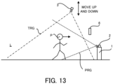
- the thermal camera 3 may be placed above the plurality of lanes L.
- the thermal camera 3 may capture the image of the plurality of target persons P that pass through the plurality of lanes L, respectively, above the plurality of lanes L. Namely, the thermal camera 3 may capture the image of the plurality of target persons P above the plurality of target persons P.
- the thermal camera 3 is not capable of properly capturing the image of one target person P due to another target person P that is located between one target person P and the thermal camera 3, compared to a case where the thermal camera 3 captures the image of the plurality of target persons P in front of the plurality of target persons P.
- the thermal camera is capable of capturing the image of the plurality of target persons P that pass through the plurality of lanes L, respectively.
- the information processing system SYS may output a message to the target person P so that the target person P turns his face toward the thermal camera 3.
- the information processing system SYS may include, at or near the gate apparatus 1, a display 6 that displays the message to the target person P so that the target person P turns his face toward the thermal camera 3.
- the thermal camera 3 even when the thermal camera 3 captures the image of the target person P above the target person P, the thermal camera 3 is capable of properly capturing the image of the surface of the body of the target person P (namely, is capable of generating the thermal image IMG T that indicates the body temperature of the target person P properly).
- the information processing system SYS may move the thermal camera 3, in addition to or instead of outputting the message to the target person P so that the target person P turns his face toward the thermal camera 3.
- the information processing system SYS may move the thermal camera 3 so that the thermal camera 3 is capable of properly capturing the image of the surface of the body (for example, the surface of the face) of the target person P in front of the target person P.
- the information processing system SYS may move the thermal camera 3 downward so that the thermal camera 3 is capable of properly capturing the image of the surface of the body of the target person P in front of the target person P.
- the information processing system SYS may move the thermal camera 3 upward. Namely, the thermal camera 3 may be movable upward and downward. As a result, even when the thermal camera 3 captures the image of the target person P above the target person P, the thermal camera 3 is capable of properly capturing the image of the surface of the body of the target person P (namely, is capable of generating the thermal image IMG_T that indicates the body temperature of the target person P properly).
- the target person P passing through the gate apparatus 1 moves from the lane part La to the lane part Lb of the lane L. Namely, the target person P moves toward a one-way direction.
- the target person P passing through the gate apparatus 1 may move from the lane part Lb to the lane part La of the lane L. Namely, a moving direction of the target person P may not be limited to one-way direction.
- the thermal camera 3 capture not only the image of the target person P that passes through the lane part La but also the image of the target person P that passes through the lane part Lb.
- the information processing system SYS may include, as the thermal camera 3, a thermal camera 3b the imaging range TRG of which is a 360-degree range.
- the thermal camera 3b may include a fish-eye lens as an optical system.
- the thermal camera 3b is capable of capturing the image of the target person P that is passing through the lane part La before the target person P that is passing through the lane part La toward the gate apparatus 1 passes through the gate apparatus 1 and capturing the image of the target person P that is passing through the lane part Lb before the target person P that is passing through the lane part Lb toward the gate apparatus 1 passes through the gate apparatus 1.
- the information processing system SYS may move the thermal camera 3 so that an imaging direction of the thermal camera 3 is inverted (namely, is changed). Specifically, the information processing system SYS may move the thermal camera 3 so that the imaging direction of the thermal camera 3 inverted from a direction along which the thermal camera 3 faces either one of the lane parts La and Lb to a direction along which the thermal camera 3 faces the other one of the lane parts La and Lb.
- the thermal camera 3 that faces the lane part La is capable of capturing the image of the target person P that is passing through the lane part La before the target person P that is passing through the lane part La toward the gate apparatus 1 passes through the gate apparatus 1.
- the thermal camera 3 that faces the lane part Lb is capable of capturing the image of the target person P that is passing through the lane part Lb before the target person P that is passing through the lane part Lb toward the gate apparatus 1 passes through the gate apparatus 1.
- the information processing system SYS may rotate the thermal camera 3 around a predetermined rotational axis.
- the information processing system SYS may rotate the thermal camera 3 around a rotational axis that extends along a vertical direction.
- the thermal camera 3 may capture the image of the target person P that passes through the lane part La but may not capture the image of the target person P that passes through the lane part Lb.
- the thermal camera 3 may capture the image of the target person P that is passing through the lane part La before the target person P that is passing through the lane part La toward the gate apparatus 1 passes through the gate apparatus 1 and capture the image of the target person P that is passing through the lane part La after the target person P that is passing through the lane part La to be away from the gate apparatus 1 passes through the gate apparatus 1.
- the thermal camera 3 may capture the image of the target person P that newly enters the management area MA and capture the image of the target person P that exits from the management area MA.
- the information processing apparatus 4 may perform an exit management operation of managing an exit of the target person P from the management area MA. For example, the information processing apparatus 4 may calculate, based on the thermal image IMG_T, the body temperature of the target person P that exits from the management area MA. Then, when the body temperature of the target person P that exits from the management area MA is not normal, the information processing apparatus 4 may output a message for giving notice of that fact. The information processing apparatus 4 may output a message for notifying an operator and so on of the management area MA that the body temperature of the target person P that exits from the management area MA is not normal.
- the thermal camera 3 captures the image of the target person P that exits from the management area MA
- the thermal camera 3 captures the image of the target person P in the rear of the target person P.
- the information processing apparatus 4 is capable of calculating, based on the thermal image IMG_T, the body temperature of the target person P that exits from the management area MA is not normal, as long as the surface of the body (for example, a back of a neck or a back of a hand) of the target person P is included in the thermal image IMG_T.
- the information processing system SYS includes the plurality of optical cameras 2 that correspond to the plurality of gate apparatuses 1, respectively.
- the information processing system SYS may include the single that corresponds to at least two gate apparatuses 1.
- the information processing system SYS includes the single that corresponds to the gate apparatuses 1#1 to 1#3.
- the optical camera 2 is placed so that at least a part of each of the lanes L#1 to L#3 is included in the imaging range RPG of the optical camera 2.
- the optical camera 2 is placed so that at least a part of the lane L#1, at least a part of the lane L#2 and at least a part of the lane L#3 are included in the imaging range RPG of the optical camera 2.
- the information processing apparatus 4 may determine one lane L through which each target person P included in the person image IMG_P is passing through by performing an operation that is same as an operation for determining one lane L through which each target person P included in the thermal image IMG T is passing through.
- the optical camera 2 is not capable of properly capturing the image of the surface of the body (for example, the surface of the face) of the target person P depending on a positional relationship between the optical camera 2 and the target person P.
- the optical camera 2 that is placed at the lane L#2 namely, placed at or near the gate apparatus 1#2 is not capable of properly capturing the image of the surface of the body of the target person P that passes through the lane L#1 or L#3.
- the information processing system SYS may output a message to the target person P so that the target person P turns his face toward the optical camera 2.
- the information processing system SYS may include, at or near the gate apparatus 1, a display 7 that displays the message to the target person P so that the target person P turns his face toward the optical camera 2.
- the information processing system SYS may include, at or near the gate apparatus 1#1, a display 7#1 that displays the message to the target person P so that the target person P that passes through the lane L#1 (namely, that moves toward the gate apparatus 1#1) turns his face toward the optical camera 2.
- the information processing system SYS may include, at or near the gate apparatus 1#2, a display 7#2 that displays the message to the target person P so that the target person P that passes through the lane L#2 (namely, that moves toward the gate apparatus 1#2) turns his face toward the optical camera 2.
- the information processing system SYS may include, at or near the gate apparatus 1#3, a display 7#3 that displays the message to the target person P so that the target person P that passes through the lane L#3 (namely, that moves toward the gate apparatus 1#3) turns his face toward the optical camera 2.
- the information processing system STYS may not all of the plurality of displays 7 that correspond to the plurality of gate apparatuses 1, respectively.
- the optical camera 2 since the optical camera 2 is placed at or near the gate apparatus 1#2, there is a relatively high possibility that the optical camera 2 is capable of properly capturing the image of the surface of the body (for example, the surface of the face) of the target person P that passes through the lane L#2 (namely, that moves toward the gate apparatus 1#2).
- the information processing system SYS may not include the display 7#2.
- the information processing apparatus 4 includes the authentication unit 412 and the entry management unit 414 in order to perform the entry management operation.
- the information processing apparatus 4 may not perform the entry management operation.
- the information processing apparatus 4 may not include the authentication unit 412 and the entry management unit 414.
- the information processing apparatus 4 may not store the entry history DB 421.
- the information processing system SYS may not include the plurality of gate apparatuses 1 and the plurality of optical cameras 2. Even in this case, the information processing apparatus 4 may obtain the thermal image IMG_T from the thermal camera 3 and determine one lane L through which the target person included in the thermal image IMG T passes.
- An information processing system including:
- the information processing apparatus includes:
- the determining unit divides the body temperature image into a plurality of image areas that respectively correspond to the plurality of lanes, and determines, as the passing lane, one lane that corresponds to one image area of the plurality of image areas that includes the target person.
- the determining unit determines a position of the target person in a world coordinate system that represents a position in a space in which the plurality of lanes are provided based on a position of a predetermined part of the target person indicated by the body temperature image, and determines the passing lane based on the determined position of the target person.
- thermo camera is movable so that an imaging direction of the thermal camera is inverted.
- An information processing apparatus including:
- An information processing method including:
Landscapes
- Physics & Mathematics (AREA)
- General Physics & Mathematics (AREA)
- Engineering & Computer Science (AREA)
- Health & Medical Sciences (AREA)
- Life Sciences & Earth Sciences (AREA)
- Human Computer Interaction (AREA)
- Spectroscopy & Molecular Physics (AREA)
- General Health & Medical Sciences (AREA)
- Veterinary Medicine (AREA)
- Molecular Biology (AREA)
- Surgery (AREA)
- Animal Behavior & Ethology (AREA)
- Biomedical Technology (AREA)
- Public Health (AREA)
- Medical Informatics (AREA)
- Pathology (AREA)
- Biophysics (AREA)
- Heart & Thoracic Surgery (AREA)
- Closed-Circuit Television Systems (AREA)
- Time Recorders, Dirve Recorders, Access Control (AREA)
- Image Analysis (AREA)
Abstract
Description
- The present disclosure relates to a technical field of an information processing system that includes a thermal camera configured to generate a body temperature information indicating a body temperature of a target person by capturing an image of the target person and an information processing apparatus that obtains the body temperature information from the thermal camera, and an information processing apparatus, an information processing method and a recording medium that obtain the body temperature information from the thermal camera, for example.
- A
Patent Literature 1 discloses a gate apparatus including, as a sensing device that detects a passing person and the like, a thermal sensor that detects a heat such as a body temperature. - Additionally, there are
Patent Literatures 2 to 4 as a background art document relating to the present disclosure. -
- Patent Literature 1:
JP2019-071126A - Patent Literature 2:
JP2001-257927A - Patent Literature 3:
JP2009-043046A - Patent Literature 4:
JP2020-205117A - Patent Literature 5:
JP2020-201999A - It is an example object of the present disclosure to provide an information processing system, an information processing apparatus, an information processing method and a recording medium that aims to an improvement of a technique disclosed in the background art document.
- One example aspect of an information processing system includes: a plurality of gate apparatuses that are respectively placed at a plurality of lanes through each of which a target person can pass; a thermal camera that is configured to generate a body temperature information indicating a body temperature of the target person by capturing an image of the target person included in an imaging range thereof, the imaging range including at least a part of each of the plurality of lanes; and an information processing apparatus that obtains the body temperature information from the thermal camera.
- One example aspect of an information processing apparatus includes: an obtaining unit that obtains a body temperature image from a thermal camera, an imaging range of the thermal camera including at least a part of each of a plurality of lanes through each of which a target person can pass and the thermal camera being configured to generate the body temperature image indicating a body temperature of the target person by capturing an image of the target person included in the imaging range; and determining unit that determines, as a passing lane, a lane of the plurality of lanes through which the target person indicated by the body temperature image passes.
- One example aspect of an information processing method includes: obtaining a body temperature image from a thermal camera, an imaging range of the thermal camera including at least a part of each of a plurality of lanes through each of which a target person can pass and the thermal camera being configured to generate the body temperature image indicating a body temperature of the target person by capturing an image of the target person included in the imaging range; and determining, as a passing lane, a lane of the plurality of lanes through which the target person indicated by the body temperature image passes.
- One example aspect of a recording medium is a recording medium on which a computer program that allows a computer to execute an information processing method is recorded, the information processing method includes: obtaining a body temperature image from a thermal camera, an imaging range of the thermal camera including at least a part of each of a plurality of lanes through each of which a target person can pass and the thermal camera being configured to generate the body temperature image indicating a body temperature of the target person by capturing an image of the target person included in the imaging range; and determining, as a passing lane, a lane of the plurality of lanes through which the target person indicated by the body temperature image passes.
-
- [
FIG. 1] FIG. 1 is a block diagram that illustrates an entire configuration of an information processing system in a present example embodiment. - [
FIG. 2] FIG. 2 is a planar view that illustrates positions of a plurality of optical cameras, a plurality of gate apparatuses and a thermal camera. - [
FIG. 3] FIG. 3 is a block diagram that illustrates a configuration of an information processing apparatus in the present example embodiment. - [
FIG. 4] FIG. 4 illustrates one example of a data structure of an entry history DB. - [
FIG. 5] FIG. 5 is a flow chart that illustrates an entire flow of an entry management operation that is performed by the information processing apparatus. - [
FIG. 6] FIG. 6 conceptually illustrates a thermal image. - [
FIG. 7] FIG. 7 conceptually illustrates the thermal image that is divided into a plurality of image areas. - [
FIG. 8] FIG. 8 conceptually illustrates the thermal image that is divided into the plurality of image areas. - [
FIG. 9] FIG. 9 is a planar view that illustrates a target person passing through a lane together with the optical camera and the thermal camera. - [
FIG. 10] FIG. 10 conceptually illustrates the thermal image. - [
FIG. 11] FIG. 11 is a planar view that illustrates a plurality of lanes that are physically separated by partition members. - [
FIG. 12] FIG. 12 conceptually illustrates the thermal image. - [
FIG. 13] FIG. 13 illustrates a position of the thermal camera in a first modified example. - [
FIG. 14] FIG. 14 conceptually illustrates a movement of the target person P in a second modified example. - [
FIG. 15] FIG. 15 conceptually illustrates the movement of the target person Pin the second modified example. - [
FIG. 16] FIG. 16 conceptually illustrates the movement of the target person P in the second modified example. - [
FIG. 17] FIG. 17 illustrates a position of the optical camera in a third modified example. - [
FIG. 18] FIG. 18 is a block diagram that illustrates a configuration of an information processing apparatus in a fourth modified example. - [
FIG. 19] FIG. 19 is a block diagram that illustrates a configuration of an information processing system in the fourth modified example. - Next, an example embodiment of an information processing system, an information processing apparatus, an information processing method and a recording medium will be described. In the below described description, the example embodiment of the information processing system, the information processing apparatus, the information processing method and the recording medium will be described by using an information processing system SYS to which the example embodiment of the information processing system, the information processing apparatus, the information processing method and the recording medium is applied.
- Firstly, a configuration of the information processing system SYS in the present example embodiment will be described.
- Firstly, with reference to
FIG. 1 , an entire configuration of the information processing system SYS in the present example embodiment will be described.FIG. 1 is a block diagram that illustrates the entire configuration of the information processing system SYS in the present example embodiment. - As illustrated in
FIG. 1 , it includes a plurality ofgate apparatuses 1, a plurality ofoptical cameras 2, athermal camera 3 and aninformation processing apparatus 4 that is one specific example of an "information processing apparatus". The plurality ofgate apparatuses 1 and theinformation processing apparatus 4 may be configured to communicate with each other through acommunication network 5. The plurality ofoptical cameras 2 and theinformation processing apparatus 4 may be configured to communicate with each other through thecommunication network 5. Thethermal camera 3 and theinformation processing apparatus 4 may be configured to communicate with each other through thecommunication network 5. Thecommunication network 4 may include a wired communication network. Thecommunication network 5 may include a wireless communication network. - The
gate apparatus 1 is an apparatus that is configured to control a passing of a target person P. A state of thegate apparatus 1 is switchable between a close state in which the target person P cannot pass through thegate apparatus 1 and an open state in which the target person P can pass through thegate apparatus 1. For example, when thegate apparatus 1 includes a gate bar 11 (seeFIG. 2 described later), the state of thegate apparatus 2 may be switchable between the close state in which thegate bar 11 is closed and the open state in which thegate bar 11 is opened. - The plurality of
gate apparatuses 1 may be placed at an entrance of a management area MA (seeFIG. 2 described later) which the target person P that satisfies a predetermined entry condition is permitted to enter and the target person P that does not satisfy the predetermined entry condition is not permitted (namely, is prohibited) to enter. In this case, when the target person P satisfies the predetermined entry condition, the state of onegate apparatus 1 through which this target person P will pass is switched to the open state. As a result, the target person P that satisfies the predetermined entry condition can enter the management area MA by passing through thegate apparatus 1 that is in the open state. On the other hand, when the target person P does not satisfy the predetermined entry condition, the state of onegate apparatus 1 through which this target person P will pass is switched to the closed state. As a result, the target person P that does not satisfy the predetermined entry condition cannot pass through thegate apparatus 1 that is in the closed state and thus cannot enter the management area MA. However, the plurality ofgate apparatuses 1 may be placed at a position that is different from the entrance of the management area MA. In the below described description, an example in which the plurality ofgate apparatuses 1 may be placed at the entrance of the management area MA will be described for convenience of description. - The
optical camera 2 is an imaging apparatus that is configured to optically capture an image of the target person P that is located in an imaging range PRG of theoptical camera 2. Theoptical camera 2 generates a person image IMG_P that indicates the target person P the image of which is captured by theoptical camera 2 by capturing the image of the target person P. The person image IMG_P that indicates the target person P may be typically an image in which the target person P is included. Note that the "person image IMG P in which the target person P is included" may include an image that is generated by means of theoptical camera 2 capturing the image of the target person P that does not have an intention of wanting theoptical camera 2 to capture the image of the target person P. The "person image IMG_P in which the target person P is included" may include an image that is generated by means of theoptical camera 2 capturing the image of the target person P that has the intention of wanting theoptical camera 2 to capture the image of the target person P. Theoptical camera 2 transmits the generated person image IMG_P to theinformation processing apparatus 4 through thecommunication network 5. - The
gate apparatuses 1 and the plurality ofoptical cameras 2 are placed so as to have one to one relationship between each other. Thus, the number of theoptical cameras 2 is equal to the number of thegate apparatuses 1. Incidentally, in the below described description, an example in which the information processing system SYS includes three gate apparatuses 1 (specifically, thegate apparatus 1#1, thegate apparatus 1#2 and thegate apparatus 1#3) and three optical cameras 2 (specifically, theoptical camera 2#1, theoptical camera 2#2 and theoptical camera 2#3) will be described for convenience of description. - Specifically, as illustrated in
FIG. 2 that is a planar view illustrating positions of thegate apparatuses 1#1 to 1#3 and theoptical cameras 2#1 to 2#3, eachgate apparatus 1 is placed at one lane L through which the target person P can pass in order to pass through eachgate apparatus 1. Furthermore, eachoptical camera 2 is placed so that the imaging range PRG of eachoptical camera 2 includes at least a part of one lane L through which the target person P can pass in order to pass through onegate apparatus 1 that corresponds to eachoptical camera 2. Especially, eachoptical camera 2 is placed so that the imaging range PRG of eachoptical camera 2 includes at least a part of an area of one lane L, which corresponds to eachoptical camera 2, through which the target person P can pass before the target person P passes through onegate apparatus 1 that corresponds to eachoptical camera 2. Namely, eachoptical camera 2 is placed so as to capture the image of the target person P that moves toward thegate apparatus 1 corresponding to eachoptical camera 2. In this case, eachoptical camera 2 is typically placed at or near thegate apparatus 1 that corresponds to eachoptical camera 2. Moreover, eachoptical camera 2 is placed so that the imaging range PRG includes at least a part of a lane part La of the lane L, which corresponds to eachoptical camera 2, through which the target person P passes before passing through the gate apparatus 1 (namely, a lane part that is located toward one side from the gate apparatus 1). On the other hand, eachoptical camera 2 may not be placed so that the imaging range PRG includes at least a part of a lane part Lb of the lane L, which corresponds to eachoptical camera 2, through which the target person P passes after passing through the gate apparatus 1 (namely, a lane part that is located toward other side from the gate apparatus 1). Thus, eachoptical camera 2 captures the image of the target person P that passes through one lane L corresponding to eachoptical camera 2 before the target person P passes through onegate apparatus 1 corresponding to eachoptical camera 2. Specifically, theoptical camera 2#1 is placed so that the imagingrange PRG# 1 of theoptical camera 2#1 includes at least a part of thelane L# 1 through which the target person P, which passes through thegate apparatus 1#1 corresponding to theoptical camera 2#1, can pass. Thus, theoptical camera 2#1 captures the image of the target person P that passes through thelane L# 1 before the target person P passes through thegate apparatus 1#1. Moreover, theoptical camera 2#2 is placed so that the imagingrange PRG# 2 of theoptical camera 2#2 includes at least a part of thelane L# 2 through which the target person P, which passes through thegate apparatus 1#2 corresponding to theoptical camera 2#2, can pass. Thus, theoptical camera 2#2 captures the image of the target person P that passes through thelane L# 2 before the target person P passes through thegate apparatus 1#2. Moreover, theoptical camera 2#3 is placed so that the imagingrange PRG# 3 of theoptical camera 2#3 includes at least a part of thelane L# 3 through which the target person P, which passes through thegate apparatus 1#3 corresponding to theoptical camera 2#3, can pass. Thus, theoptical camera 2#3 captures the image of the target person P that passes through thelane L# 3 before the target person P passes through thegate apparatus 1#3. - The
lanes L# 1 to L#3 (namely, the plurality of lanes) may not be physically separated (in other words, isolated). Thelanes L# 1 toL# 3 may not be physically divided. However, thelanes L# 1 toL# 3 may be physically separated. For example, thelanes L# 1 toL# 3 may be physically separated by a structural object (for example, a fence) for physically separating thelanes L# 1 toL# 3. - Again in
FIG. 1 , thethermal camera 3 is an imaging apparatus that is configured to capture an image of the target person P that is located in an imaging range TRG of thethermal camera 3. Thethermal camera 3 generates a body temperature information that indicates a body temperature of the target person P the image of which is captured by thethermal camera 3 by capturing the image of the target person P. The body temperature information may include an image information (namely, a body temperature image, and it is referred to as a "thermal image IMG_T" hereinafter) that indicates the body temperature of the target person P. The thermal image IMG T may be an image that indicates a distribution of the body temperature of the target person by a color or a contrast. The body temperature information may include a numerical information that quantitatively indicates the body temperature of the target person. The body temperature information may include any data that directly or indirectly indicates the body temperature of the target person. Incidentally, in the below describe description, an example in which thethermal camera 3 generates the thermal image IMG T will be described for convenience of description. Typically, the thermal image IMG_T indicating the body temperature of the target person P may be an image in which the target person P is substantially included by the distribution of the body temperature of the target person P. Note that the "thermal image IMG T in which the target person P is included" may include an image that is generated by means of thethermal camera 3 capturing the image of the target person P that does not have an intention of wanting thethermal camera 3 to capture the image of the target person P. The "thermal image IMG T in which the target person P is included" may include an image that is generated by means of thethermal camera 3 capturing the image of the target person P that has the intention of wanting thethermal camera 3 to capture the image of the target person P. Thethermal camera 3 transmits the generated thermal image IMG_T (namely, the generated body temperature information) to theinformation processing apparatus 4 through thecommunication network 5. - As illustrated in
FIG. 2 that illustrates a position of thethermal camera 3, thethermal camera 3 is placed so that the imaging range TRG of thethermal camera 3 includes at least a part of each of the plurality of lanes L. Namely, thethermal camera 3 is placed so that the imaging range TRG of thethermal camera 3 includes at least a part of thelane L# 1, at least a part of thelane L# 2 and at least a part of thelane L# 3. Especially, thethermal camera 3 is placed so that the imaging range TRG of thethermal camera 3 includes at least a part of an area of each lane L through which the target person P can pass before the target person P passes through onegate apparatus 1 that corresponds to each lane L. Namely, thethermal camera 3 is placed so as to capture the image of the target person P that moves toward thegate apparatus 1. In this case, thethermal camera 3 is typically placed at or near either one of the plurality ofgate apparatuses 1. Thus, thethermal camera 3 captures the image of the target person P that passes through each lane L corresponding to eachgate apparatus 1 before the target person P passes through eachgate apparatus 1. Specifically, thethermal camera 3 captures the image of the target person P that passes through thelane L# 1 before the target person P passes through thegate apparatus 1#1. Moreover, thethermal camera 3 captures the image of the target person P that passes through thelane L# 2 before the target person P passes through thegate apparatus 1#2. Moreover, thethermal camera 3 captures the image of the target person P that passes through thelane L# 3 before the target person P passes through thegate apparatus 1#3. - Again in
FIG. 1 , theinformation processing apparatus 4 obtains the person image IMG_P from at least one of the plurality ofoptical cameras 2. Furthermore, theinformation processing apparatus 4 obtains the thermal image IMG_T (namely, the body temperature information) from thethermal cameras 3. Theinformation processing apparatus 4 performs a desired operation based on the obtained person image IMG P and thermal image IMG_T (namely, the body temperature information). - In the below described description, an example in which the
information processing apparatus 4 performs, as one example of the desired operation, an entry management operation for managing an entry of the target person P to the management area MA at which thegate apparatuses 1#1 to 1#3 are placed. The entry management operation may include an operation for authenticating the target person P included in the person image IMG_P (namely, determining whether or not the target person P is same as a registered person) based on the person image IMG_P. In this case, the entry condition that should be satisfied for the target person P to enter the management area MA may include an authentication condition that the authentication of the target person succeeds (namely, the target person P is same as the registered person). Moreover, the entry management operation may include an operation for determining the body temperature of the authenticated target person P based on the thermal image IMG_T and determining whether or not the determined body temperature is normal (typically, is lower than an allowable upper limit value). In this case, the entry condition that should be satisfied for the target person P to enter the management area MA may include a body temperature condition that the body temperature of the target person is normal. - Next, with reference to
FIG. 3 , a configuration of theinformation processing apparatus 4 will be described.FIG. 3 is a block diagram that illustrates the configuration of theinformation processing apparatus 4. - As illustrated in
FIG. 3 , theinformation processing apparatus 4 includes anarithmetic apparatus 41, astorage apparatus 42 and acommunication apparatus 43. Furthermore, theinformation processing apparatus 4 may include aninput apparatus 44 and anoutput apparatus 45. However, theinformation processing apparatus 4 may not include at least one of theinput apparatus 44 and theoutput apparatus 45. Thearithmetic apparatus 41, thestorage apparatus 42, thecommunication apparatus 43, theinput apparatus 44 and theoutput apparatus 45 may be interconnected through adata bus 46. - The
arithmetic apparatus 41 includes at least one of a CPU (Central Processing Unit), a GPU (Graphic Processing Unit) and a FPGA (Field Programmable Gate Array), for example. Thearithmetic apparatus 41 reads a computer program. For example, thearithmetic apparatus 41 may read a computer program that is stored in thestorage apparatus 42. For example, thearithmetic apparatus 41 may read a computer program that is stored in a non-transitory computer-readable recording medium by using a non-illustrated recording medium reading apparatus of theinformation processing apparatus 4. Thearithmetic apparatus 41 may obtain (namely, download or read) a computer program from a non-illustrated apparatus that is placed outside theinformation processing apparatus 4 through the communication apparatus 43 (alternatively, other communication apparatus) Thearithmetic apparatus 41 executes the read computer program. As a result, a logical functional block for performing an operation (for example, the above described entry management operation) that should be performed by theinformation processing apparatus 4 is implemented in thearithmetic apparatus 41. Namely, thearithmetic apparatus 41 is configured to serve as a controller for implementing the logical functional block for performing the operation (in other words, a processing) that should be performed by theinformation processing apparatus 4. -
FIG. 3 illustrates one example of the logical functional block that is implemented in thearithmetic apparatus 41 for performing the entry management operation. As illustrated inFIG. 3 , in thearithmetic apparatus 41, animage obtaining unit 411 that is one specific example of "an obtaining unit", anauthentication unit 412 that is one specific example of "an authenticating unit", a bodytemperature calculation unit 413 that is one specific example of "a determining unit" and anentry management unit 414 that is one specific example of "a generating unit" are implemented. Note that a detail of an operation of each of theimage obtaining unit 411, theauthentication unit 412, the bodytemperature calculation unit 413 and theentry management unit 414 will be described later in detail, however, a summary thereof will be described briefly here. Theimage obtaining unit 411 obtains the person image IMG_P from at least one of the plurality ofoptical cameras 2. Furthermore, the obtainingunit 411 obtains the thermal image IMG_T from thethermal camera 3. Theauthentication unit 412 authenticates the target person P included in the person image IMG_P (namely, determining whether or not the target person P is same as the registered person) based on the person image IMG_P. The bodytemperature calculation unit 413 calculates, based on the thermal image IMG_T, the body temperature of the target person P that is authenticated by theauthentication unit 412. Theentry management unit 414 manages the entry of the target person P to the management area MA. Furthermore, theentry management unit 414 generates an entry history DB (DataBase) 421 for managing an entry history of the target person P to the management area MA. -
FIG. 4 illustrates one example of a data structure of theentry history DB 421. As illustrated inFIG. 4 , it includes a history record 4210. The history record 4210 may include anidentification information 4211 for identifying the target person P, atime information 4212 that indicates a time at which the target person P is authenticated, abody temperature information 4213 that indicates the body temperature of the target person P, agate information 4214 for identifying thegate apparatus 1 through which the target person P has passed (alternatively, tried to pass), and an entry permission information 4215 that indicates whether or not entry of the target person P has been permitted. In this manner, theidentification information 4211 for identifying the target person P is associated with thebody temperature information 4213 that indicates the body temperature of the target person P in the history record 4210. Note that an information indicating a name of the target person P is used as theidentification information 4211 in an example illustrated inFIG. 4 . - Again in
FIG. 3 , thestorage apparatus 42 is configured to store a desired data. For example, thestorage apparatus 42 may temporarily store the computer program that is executed by thearithmetic apparatus 41. Thestorage apparatus 42 may temporarily store a data that is temporarily used by thearithmetic apparatus 41 when thearithmetic apparatus 41 executes the computer program. Thestorage apparatus 42 may store a data that is stored for a long term by theinformation processing apparatus 4. Especially in the present example embodiment, thestorage apparatus 42 may store theentry history DB 421. Note that thestorage apparatus 42 may include at least one of a RAM (Random Access Memory), a ROM (Read Only Memory), a hard disk apparatus, a magneto-optical disc, a SSD (Solid State Drive) and a disk array apparatus. Namely, thestorage apparatus 42 may include a non-transitory recording medium. - The
communication apparatus 43 is configured to communicate with the plurality ofoptical cameras 2 and thethermal camera 3 through thecommunication network 5. In the present example embodiment, thecommunication apparatus 43 receives (namely, obtains) the person image IMG_P from at least one of the plurality ofoptical cameras 2 through thecommunication network 5. Furthermore, thecommunication apparatus 43 receives (namely, obtains) the thermal image IMG_T from thethermal camera 3 through thecommunication network 5. - The
input apparatus 44 is an apparatus that receives an input of an information from an outside of theinformation processing apparatus 4 to theinformation processing apparatus 4. For example, theinput apparatus 44 may include an operational apparatus (for example, at least one of a keyboard, a mouse and a touch panel) that is operable by an operator of theinformation processing apparatus 4. For example, theinput apparatus 44 may include a reading apparatus that is configured to read an information recorded as a data in a recording medium that is attachable to theinformation processing apparatus 4. - The
output apparatus 45 is an apparatus that outputs an information to an outside of theinformation processing apparatus 4. For example, theoutput apparatus 45 may output the information as an image. Namely, theoutput apparatus 45 may include a display apparatus (what we call a display) that is configured to display the image representing the information to be outputted. For example, theoutput apparatus 45 may output the information as a sound. Namely, theoutput apparatus 45 may include an audio apparatus (what we call a speaker) that is configured to output the sound. For example, theoutput apparatus 45 may output the information on a paper. Namely, theoutput apparatus 45 may include a print apparatus (what we call a printer) that is configured to print a desired information on the paper. - Next, the entry management operation that is performed by the
information processing apparatus 4 will be described. - Firstly, with reference to
FIG. 5 , an entire flow of the entry management operation that is performed by theinformation processing apparatus 4 will be described.FIG. 5 is a flowchart that illustrates the entire flow of the entry management operation that is performed by theinformation processing apparatus 4. - As illustrated in
FIG. 5 , theimage obtaining unit 411 obtains the person image IMG_P from at least one of the plurality of optical cameras 2 (a step S1). Then, theauthentication unit 412 authenticates the target person P that is included in the person image IMG_P obtained at the step S1 based on the person image IMG_P obtained at the step S1 (a step S2). Specifically, theauthentication unit 412 authenticates the target person P that passes through the lane L#1 (namely, the target person P that moves toward thegate apparatus 1#1 in order to pass through thegate apparatus 1#1) based on the person image IMG_P obtained from theoptical camera 2#1. Similarly, theauthentication unit 412 authenticates the target person P that passes through the lane L#2 (namely, the target person P that moves toward thegate apparatus 1#2 in order to pass through thegate apparatus 1#2) based on the person image IMG_P obtained from theoptical camera 2#2. Similarly, theauthentication unit 412 authenticates the target person P that passes through the lane L#3 (namely, the target person P that moves toward thegate apparatus 1#3 in order to pass through thegate apparatus 1#3) based on the person image IMG_P obtained from theoptical camera 2#3. - The
authentication unit 412 may perform a face authentication operation for authenticating the target person P by using a feature point of a face of the target person P included in the person image IMG_P. Theauthentication unit 412 may perform an iris authentication operation for authenticating the target person P by using a feature point of an iris of the target person P included in the person image IMG P. - In parallel with the operation from the step S1 to the step S2, the
image obtaining unit 411 obtains the thermal image IMG_T from the thermal camera 3 (a step S3). Then, the bodytemperature calculation unit 413 calculates, based on the thermal image IMG T obtained at the step S3, the body temperature of the target person P that is authenticated at the step S2 (a step S4) - Here, as described above, the imaging range TRG of the
thermal camera 3 includes at least a part of each of the plurality of lanes L. Thus, as illustrated inFIG. 6 that conceptually illustrates the thermal image IMG_T, there is a possibility that the target person P that is passing through either one of thelanes # 1 toL# 3 and the target person P that is passing through another one of thelanes # 1 toL# 3 are included in the thermal image IMG T at the same time. Namely, there is a possibility that the plurality of target persons P that pass through the plurality of different lanes L, respectively, are included in the thermal image IMG_T. Thus, in the present example embodiment, the bodytemperature calculation unit 413 determines one lane L through which each target person P included in the thermal image IMG_T is passing through in order to calculate the body temperature of the target person P authenticated at the step S2. Then, the bodytemperature calculation unit 413 calculates, based on the thermal image IMG_T, the body temperature of each target person P that is passing through the determined one lane L as the body temperature of each target person P that is authenticated based on the person image IMG_P obtained from oneoptical camera 2 corresponding to the determined one lane L. Specifically, when the person image IMG P is obtained from theoptical camera 2#1 at the step S2, the target person P included in the person image IMG_P is passing through thelane L# 1. In this case, the bodytemperature calculation unit 413 determines the target person P that is passing through thelane L# 1 in the thermal image IMG_T by determining one lane L through which each target person P included in the thermal image IMG_T is passing, and calculates the body temperature of the determined target person P as the body temperature of the target person P that is passing through the lane L# 1 (namely, the target person P that is included in the person image IMG_P obtained from theoptical camera 2#1). The same applies to a case where the person image IMG P is obtained from theoptical camera 2#2 or 2#3 at the step S2. As a result, even when thethermal camera 3 captures the image of the plurality of target persons P that pass through the plurality of different lanes L, respectively, the bodytemperature calculation unit 413 is capable of properly calculating the body temperatures of the plurality of target persons P that pass through the plurality of different lanes L, respectively. - Note that the operation for determining one lane L through which each target person P included in the thermal image IMG_T is passing will be described later in detail with reference to
FIG. 7 and so on, and thus a description thereof is omitted here. - Again in
FIG. 5 , then, theentry management unit 414 determines whether or not to permit the target person P, which is include in the person image IMG_P obtained at the step S1, to enter the management area MA (a step S6). Specifically, when the authentication of the target person P succeeds at the step S2 and the body temperature of the target person calculated at the step S4 is normal (typically, is lower than the allowable upper limit value), theentry management unit 414 may determine to permit the target person P to enter the management area MA. On the other hand, when the authentication of the target person P does not succeed at the step S2 and / or the body temperature of the target person calculated at the step S4 is not normal (typically, is higher than the allowable upper limit value), theentry management unit 414 may determine not to permit the target person P to enter the management area MA. - As a result of the determination at the step S6, when it is determined that the target person P is permitted to enter the management area MA (the step S6: Yes), the
entry management unit 414 controls the state of onegate apparatus 1 so that the state of onegate apparatus 1 through which the target person P will pass (namely, onegate apparatus 1 corresponding to oneoptical camera 2 that generates the person image IMG_P in which the target person P is included) becomes the open state (a step S7). For example, theentry management unit 414 may transmits, to onegate apparatus 1, a control signal for setting the state of onegate apparatus 1 to be the open state through thecommunication network 5. As a result, the target person P can enter the management area MA by passing through thegate apparatus 1 that is in the open state. - On the other hand, as a result of the determination at the step S6, when it is determined that the target person P is not permitted to enter the management area MA (the step S6: No), the
entry management unit 414 controls the state of onegate apparatus 1 so that the state of onegate apparatus 1 through which the target person P will pass (namely, onegate apparatus 1 corresponding to oneoptical camera 2 that generates the person image IMG_P in which the target person P is included) becomes the close state (a step S8). For example, theentry management unit 414 may transmits, to onegate apparatus 1, a control signal for setting the state of onegate apparatus 1 to be the close state through thecommunication network 5. As a result, the target person P cannot pass through thegate apparatus 1 that is in the close state and thus cannot enter the management area MA. - Then, the
entry management unit 414 updates the entry history DB 421 (a step S9). Specifically, theentry management unit 414 adds, to theentry history DB 421, a new history record 4210 that includes an information relating to an authenticated result of the target person at the step S2 (specifically, theidentification information 4211, thetime information 4212 and theauthentication information 4214 described above), an information relating to the body temperature of the target person P calculated at the step S4 (specifically, the body temperature information 4213) and an information relating to a determined result at the step S6 (specifically, the entry permission information 4215). - Next, the operation for determining one lane L through which each target person P included in the thermal image IMG_T is passing will be described.
- Firstly, with reference to
FIG. 7 , a first specific example of the operation for determining one lane L through which each target person P included in the thermal image IMG T is passing will be described.FIG. 7 conceptually illustrates the thermal image IMG_T. - As illustrated in
FIG. 7 , in the first specific example, the bodytemperature calculation unit 413 divides the thermal image IMG_T into a plurality of image areas TR (specifically, imageareas TR# 1 to TR#3) that corresponds to thelanes L# 1 to L#3 (namely, the plurality of lanes L). The imagearea TR# 1 is an image area in which the target person P passing through thelane L# 1 is expected to be included in the thermal image IMG_T. The imagearea TR# 2 is an image area in which the target person P passing through thelane L# 2 is expected to be included in the thermal image IMG_T. The imagearea TR# 3 is an image area in which the target person P passing through thelane L# 3 is expected to be included in the thermal image IMG_T. - Then, the body
temperature calculation unit 413 determines, as one lane L through which each target person P is passing, one lane L that corresponds to one image area TR of the imageareas TR# 1 toTR# 3 in which each target person P is included. For example, in an example illustrated inFIG. 7 , the target person P#a is included in the imagearea TR# 1 and the target person P#b is included in the imagearea TR# 2. In this case, the bodytemperature calculation unit 413 determines thelane # 1 as the lane L through which the target person P#a is passing. As a result, the bodytemperature calculation unit 413 calculates, based on the thermal image IMG_T, the body temperature of the target person P#a included in the thermal image IMG_T as the body temperature of the target person P that is passing through the lane L#1 (namely, the target person P that is included in the person image IMG_P obtained from theoptical camera 2#1). Similarly, the bodytemperature calculation unit 413 determines thelane # 2 as the lane L through which the target person P#b is passing. As a result, the bodytemperature calculation unit 413 calculates, based on the thermal image IMG_T, the body temperature of the target person P#b included in the thermal image IMG T as the body temperature of the target person P that is passing through the lane L#2 (namely, the target person P that is included in the person image IMG_P obtained from theoptical camera 2#2). - The body
temperature calculation unit 413 may divide the thermal image IMG T into the imageareas TR# 1 toTR# 3 based on positions of thelanes L# 1 to L#3 (namely, the positions of thegate apparatuses 1#1 to 1#3), the position of thethermal camera 3 and an optical characteristic (for example, the imaging range TRG) of thethermal camera 3. Thus, in the first specific example, it is preferable that an information relating to the positions of thelanes L# 1 to L#3 (namely, the positions of thegate apparatuses 1#1 to 1#3), the position of thethermal camera 3 and the optical characteristic (for example, the imaging range TRG) of thethermal camera 3 be an information that is known to the bodytemperature calculation unit 413. - A characteristic of at least one of the image
areas TR# 1 toTR# 3 may be fixed. Note that the characteristic of the image area TR may include at least one of a size of the image area TR and a shape of the image area TR. Alternatively, the bodytemperature calculation unit 413 may change the characteristic of at least one of the imageareas TR# 1 toTR# 3. For example, when at least one of the positions of thelanes L# 1 to L#3 (namely, the positions of thegate apparatuses 1#1 to 1#3), the position of thethermal camera 3 and the optical characteristic (for example, the imaging range TRG) of thethermal camera 3 changes, the bodytemperature calculation unit 413 may change the characteristic of at least one of the imageareas TR# 1 toTR# 3. As one example,FIG. 7 illustrates one example of the imageareas TR# 1 toTR# 3 when thethermal camera 2 is placed at thelane L# 2 that is located between thelane L# 1 and thelane L# 3, for example. On the other hand, when thethermal camera 3 is placed at thelane L# 1, the bodytemperature calculation unit 413 may divide the thermal image IMG_T into the imageareas TR# 1 toTR# 3 illustrated inFIG. 8 the characteristics of which are different from those of the imageareas TR# 1 toTR# 3 illustrated inFIG. 7 . - Next, with reference to
FIG. 9 , a second specific example of the operation for determining one lane L through which each target person P included in the thermal image IMG T is passing will be described.FIG. 9 is a planar view that illustrates the targetpersons P# 1 toP# 3 that pass through thelanes L# 1 toL# 3, respectively, together with theoptical cameras 2#1 to 2#3 and thethermal camera 3. - As illustrated in
FIG. 9 , theoptical cameras 2#1 to 2#3 respectively capture the images of the targetpersons P# 1 toP# 3 that respectively pass through thelanes L# 1 toL# 3. In this case, the bodytemperature calculation unit 413 calculates, in a world coordinate system for representing a position in a space in which thelane L# 1 toL# 3 are provided (namely, thegate apparatuses 1#1 to 1#3 are placed), a position of the target person P#k included in the person image IMG_P based on the person image IMG_P that is generated by theoptical camera 2#k (note that k is a variable number indicating 1, 2 or 3). In order to calculate the position of the target person P#k in the world coordinate system, the bodytemperature calculation unit 413 calculates, in a person image coordinate system for representing a position in the person image IMG_P, a position of a right eye (alternatively, another part that is different from the right eye) of the target person P#k based on the person image IMG_P, for example. Then, the bodytemperature calculation unit 413 calculates the position of the target person P#k in the world coordinate system based on the position of the right eye of the target person P#k, the positions of thelanes L# 1 to L#3 (namely, the positions of thegate apparatuses 1#1 to 1#3), the position of theoptical camera 2#k, a characteristic (for example, the imaging range PRG#k) of theoptical camera 2#k and an average distance between eyes (namely, an average value of a distance between both eyes of a human). As a result, the bodytemperature calculation unit 413 is capable of accurately determining whether or not the target person P#k included in the person image IMG_P is the target person P that is passing through the lane L#k (namely, is the target person P that is moving toward thegate apparatus 1#k placed at the lane L#k). Namely, even when the target person that is different from the target person P#k (specifically, the target person passing through the lane L that is different from the lane L#k) is included in the person image IMG_P that is generated by theoptical camera 2#k, the target person P#k that is passing through the lane L#k is extractable from the person image IMG_P. Note that one example of technique for extracting the target person P#k that is passing through the lane L#k is disclosed in thePatent Literature 5, for example. - Then, the body
temperature calculation unit 413 calculates a timing at which the target person P#k passes through the lane L#k based on the position of the target person P#k I the world coordinate system. Specifically, the bodytemperature calculation unit 413 calculates a timing at which the target person P#k reaches thegate apparatus 1#k placed at the lane L#k based on the position of the target person P#k I the world coordinate system. Then, the bodytemperature calculation unit 413 determines one lane L through which each target person P included in the thermal image IMG T is passing based on the calculated timing and the thermal image IMG T. Specifically, as illustrated inFIG. 10 that illustrates one example of the thermal image IMG_T, each target person P#k is included in the thermal image IMG_T to exist in a position nearer to a front side as a distance between thethermal camera 3 and each target person P#k becomes shorter, because thethermal camera 3 captures the image of the target person P#k that moves toward thegate apparatus 1#k. Typically, a size of each target person P#k included in the thermal image IMG_T becomes larger as the distance between thethermal camera 3 and each target person P#k becomes shorter. Thus, the distance between thethermal camera 3 and each target person P#k becomes shorter as the target person P#k reaches thegate apparatus 1#k earlier, and thus, each target person P#k is included in the thermal image IMG_T to exist in the position nearer to the front side. Therefore, since the position in the thermal image IMG T at which each target person P#k exists has a correlation with the timing at which the target person P#k reaches thegate apparatus 1#k, the bodytemperature calculation unit 413 is capable of determining one lane L through which each target person P included in the thermal image IMG T is passing based on the thermal image IMG_T and the timing at which the target person P#k reaches thegate apparatus 1#k. - In an example illustrated in
FIG. 9 , the bodytemperature calculation unit 413 recognizes that a timing at which the targetperson P# 2 reaches thegate apparatus 1#2 is the earliest, a timing at which the targetperson P# 3 reaches thegate apparatus 1#3 is the second earliest and a timing at which the targetperson P# 1 reaches thegate apparatus 1#1 is the latest, by calculating the timings at which the targetpersons P# 1 toP# 3 reach thegate apparatuses 1#1 to 1#3, respectively. In this case, the target person P#a is included in the thermal image IMG_T illustrated inFIG. 10 to exist in the position that is nearest to the front side. Thus, the bodytemperature calculation unit 413 determines thelane L# 2 through which the targetperson P# 2, which reaches thegate apparatus 1 at the earliest timing, is passing as one lane L through which the target person P#a included in the thermal image IMG T is passing. As a result, the bodytemperature calculation unit 413 calculates, based on the thermal image IMG_T, the body temperature of the target person P#a included in the thermal image IMG T as the body temperature of the targetperson P# 2 that is passing through the lane L#2 (namely, the targetperson P# 2 that is included in the person image IMG_P obtained from theoptical camera 2#2). Moreover, the target person P#b is included in the thermal image IMG_T illustrated inFIG. 10 to exist in the position that is second nearest to the front side. Thus, the bodytemperature calculation unit 413 determines thelane L# 3 through which the targetperson P# 3, which reaches thegate apparatus 1 at the second earliest timing, is passing as one lane L through which the target person P#b included in the thermal image IMG_T is passing. As a result, the bodytemperature calculation unit 413 calculates, based on the thermal image IMG_T, the body temperature of the target person P#b included in the thermal image IMG_T as the body temperature of the targetperson P# 3 that is passing through the lane L#3 (namely, the targetperson P# 3 that is included in the person image IMG_P obtained from theoptical camera 2#3). Moreover, the target person P#c is included in the thermal image IMG T illustrated inFIG. 10 to exist in the position that is farthest from the front side. Thus, the bodytemperature calculation unit 413 determines thelane L# 1 through which the targetperson P# 1, which reaches thegate apparatus 1 at the latest timing, is passing as one lane L through which the target person P#c included in the thermal image IMG T is passing. As a result, the bodytemperature calculation unit 413 calculates, based on the thermal image IMG_T, the body temperature of the target person P#c included in the thermal image IMG_T as the body temperature of the targetperson P# 1 that is passing through the lane L#1 (namely, the targetperson P# 1 that is included in the person image IMG_P obtained from theoptical camera 2#1). - Next, a third specific example of the operation for determining one lane L through which each target person P included in the thermal image IMG T is passing will be described. In the third specific example, the body
temperature calculation unit 413 calculates the position of the target person P included in the thermal image IMG T in the world coordinate system based on the thermal image IMG_T. An operation for calculating the position of the target person P included in the thermal image IMG T may be same as an operation for calculating the position of the target person P included in the person image IMG_P described in the second specific example. Namely, the bodytemperature calculation unit 413 may calculate, in a thermal image coordinate system for representing a position in the thermal image IMG_T, a position of the right eye (alternatively, another part that is different from the right eye) of the target person P#k based on the thermal image IMG_T. Then, the bodytemperature calculation unit 413 mayt calculate the position of the target person P#k in the world coordinate system based on the position of the right eye of the target person P#k, the positions of thelanes L# 1 to L#3 (namely, the positions of thegate apparatuses 1#1 to 1#3), the position of thethermal camera 3, the characteristic (for example, the imaging range TRG) of thethermal camera 3 and the average distance between eyes (namely, the average value of the distance between both eyes of the human). - As a result, the body
temperature calculation unit 413 is capable of accurately determining whether or not the target person P#k included in the thermal image IMG_T is the target person P that is passing through the lane L#k (namely, is the target person P that is moving toward thegate apparatus 1#k placed at the lane L#k). Namely, the bodytemperature calculation unit 413 is capable of accurately determining the lane L through which the target person P included in the thermal image IMG T is passing. - Incidentally, when the position of the target person P in the world coordinate system is calculated, it can be said that the body
temperature calculation unit 413 substantially calculates the distance between thethermal camera 3 and the target person P. Namely, it can be said that the bodytemperature calculation unit 413 substantially calculates a distance between thegate apparatus 1 and the target person P. In this case, the bodytemperature calculation unit 413 may perform an operation considering the distance between thegate apparatus 1 and the target person P. For example, the bodytemperature calculation unit 413 may calculate the body temperature of the target person P that is included in the thermal image IMG_T and that is so close to the gate apparatus that the distance between thegate apparatus 1 and the target person P is shorter than a predetermined distance. On the other hand, the bodytemperature calculation unit 413 may not calculate the body temperature of the target person P that is included in the thermal image IMG_T and that is so far from the gate apparatus until the distance between thegate apparatus 1 and the target person P is longer than the predetermined distance. This is because the target person P takes more time to reach thegate apparatus 1 and a necessity for calculating the body temperature of the target person is relatively low. - Alternatively, as described in the second specific example, each target person P is included in the thermal image IMG_T to exist in the position nearer to the front side as the distance between the
gate apparatus 1 and each target person P becomes shorter. Typically, the size of each target person P included in the thermal image IMG T becomes larger as the distance between thegate apparatus 1 and each target person P becomes shorter. Therefore, it can be said that a state (for example, a size) of the target person P included in the thermal image IMG_T includes an information relating to the distance between thegate apparatus 1 and the target person P. Thus, the bodytemperature calculation unit 413 may perform the operation considering the distance between thegate apparatus 1 and the target person P based on the state (for example, the size) of the target person P included in the thermal image IMG_T without calculating the position of the target person P in the world coordinate system based on the thermal image IMG_T. - Next, with reference to
FIG. 11 , a fourth specific example of the operation for determining one lane L through which each target person P included in the thermal image IMG T is passing will be described.FIG. 11 is a planar view that illustrates thelanes L# 1 toL# 3. - As illustrated in
FIG. 11 , in the fourth specific example, adjacent two lanes L of thelanes L# 1 to L#3 (namely, the plurality of lanes L) are physically separated by a partition member BD. Specifically, adjacentlanes L# 1 andL# 2 are physically separated by a partitionmember BD# 12 that is placed at a border between thelanes L# 1 andL# 2. Adjacentlanes L# 2 andL# 3 are physically separated by a partitionmember BD# 23 that is placed at a border between thelanes L# 2 andL# 3. - A temperature of the partition member BD is set to be a temperature that is different from a temperature of a space in which the
lanes L# 1 toL# 3 are provided (namely, thegate apparatus 1#1 to 1#3 are placed). For example, the partition member BD may be a member that is less susceptible to the temperature of the space in which the partition member BD is placed. In this case, even when an operation for adjusting the temperature of the partition member BD is not performed, there is a higher possibility that the temperature of the partition member BD is the temperature that is different from the temperature of the space in which the partition member BD is placed. Alternatively, the temperature of the partition member BD may be adjusted by a temperature adjustment apparatus that is configured to adjust the temperature of the partition member BD. The temperature adjustment apparatus may include at least one of an air cooling apparatus and a water cooling apparatus. In this case, the temperature adjustment apparatus may adjust the temperature of the partition member BD so that the temperature of the partition member BD is the temperature that is different from the temperature of the space in which the partition member BD is placed - When the partition member BD is placed, not only the target person P but also the partition member BD are included in the thermal image IMG_T. In this case, as illustrated in
FIG. 12 that illustrates the thermal image IMG T in which the partition member BD is included, the partition member BD is included in the thermal image IMG T in an aspect in which the partition member BD is distinguishable. This is because the temperature of the partition member BD is the temperature that is different from the temperature of the space in which the partition member BD is placed as described above. - As a result, the body
temperature calculation unit 413 is capable of determining one lane L through which the target person P included in the thermal image IMG T is passing based on a positional relationship between the partition member BD and the target person P in the thermal image IMG_T. Namely, the bodytemperature calculation unit 413 is capable of determining one lane L through which the target person P included in the thermal image IMG_T is passing based on a of the partition member BD and the position of the target person P in the thermal image IMG T. For example, in an example illustrated inFIG. 12 , when the target person P is included at the left of the partitionmember BD# 12 in the thermal image IMG_T, the bodytemperature calculation unit 413 is capable of determining thelane L# 1 as one lane L through which the target person P is passing. For example, when the target person P is included between the partitionmember BD# 12 and the partitionmember BD# 23 in the thermal image IMG_T, the bodytemperature calculation unit 413 is capable of determining thelane L# 2 as one lane L through which the target person P is passing. For example, when the target person P is included at the right of the partitionmember BD# 23 in the thermal image IMG_T, the bodytemperature calculation unit 413 is capable of determining thelane L# 3 as one lane L through which the target person P is passing. - As described above, in the information processing system SYS in the present example embodiment, at least a part of each of the plurality of lanes L are included in the imaging range TRG of the
thermal camera 3. Thus, thethermal camera 3 is capable of capturing the image of the plurality of target persons P that pass through the plurality of lanes L, respectively. As a result, the information processing system SYS may not include a plurality ofthermal cameras 3 the imaging ranges TRG of which include the plurality of lanes L, respectively. Namely, the information processing system SYS may not include the plurality ofthermal cameras 3 that respectively capture the images of the plurality of target persons P that respectively pass through the plurality of lanes L. Thus, a cost of the information processing system SYS is reducible. - Moreover, the
information processing apparatus 4 determines one lane L through which each target person P included in the thermal image IMG T is passing. Thus, even when hethermal camera 3 captures the image of the plurality of target persons P that pass through the plurality of different lanes L, respectively, the bodytemperature calculation unit 413 is capable of properly calculating the body temperatures of the plurality of target persons P that pass through the plurality of different lanes L, respectively. - Moreover, the
information processing apparatus 4 may divide the thermal image IMG_T into the plurality of image areas TR and determine, as one lane L through which the target person P included in the thermal image IMG T is passing, one lane L that corresponds to one image area TR of the plurality of image areas TR in which the target person P is included. In this case, theinformation processing apparatus 4 is capable of determining one lane L through which the target person P is passing relatively easily. - Moreover, the body
temperature calculation unit 413 may calculate the timing at which the target person P included in the person image IMG P reaches thegate apparatus 1 and determine one lane L through which the target person P included in the thermal image IMG T is passing based on the calculated timing. In this case, theinformation processing apparatus 4 is capable of determining one lane L through which the target person P is passing relatively accurately. - Moreover, the body
temperature calculation unit 413 may calculate the position of the target person P included in the thermal image IMG T in the world coordinate system based on the thermal image IMG_T and determine one lane L through which the target person P included in the thermal image IMG_T is passing based on the calculated position. In this case, theinformation processing apparatus 4 is capable of determining one lane L through which the target person P is passing relatively accurately. - Moreover, the body
temperature calculation unit 413 may determine one lane L through which the target person P included in the thermal image IMG T is passing based on the positional relationship between the partition member BD and the target person P in the thermal image IMG T. In this case, theinformation processing apparatus 4 is capable of determining one lane L through which the target person P is passing relatively easily and relatively accurately. - Next, a modified example of the information processing system SYS will be described.
- In a first modified example, as illustrated in
FIG. 13 that illustrates the position of thethermal camera 3 in the first modified example, thethermal camera 3 may be placed above the plurality of lanes L. Thethermal camera 3 may capture the image of the plurality of target persons P that pass through the plurality of lanes L, respectively, above the plurality of lanes L. Namely, thethermal camera 3 may capture the image of the plurality of target persons P above the plurality of target persons P. In this case, the there is a lower possibility that thethermal camera 3 is not capable of properly capturing the image of one target person P due to another target person P that is located between one target person P and thethermal camera 3, compared to a case where thethermal camera 3 captures the image of the plurality of target persons P in front of the plurality of target persons P. As a result, the thermal camera is capable of capturing the image of the plurality of target persons P that pass through the plurality of lanes L, respectively. - However, when the
thermal camera 3 captures the image of the target person P above the target person P, there is a possibility that thethermal camera 3 is not capable of properly capturing the image of a surface of a body (for example, a surface of a face) of the target person P due to at least one of a hair of the target person P and a cap which the target person P wears. Thus, in the first modified example, the information processing system SYS may output a message to the target person P so that the target person P turns his face toward thethermal camera 3. For example, the information processing system SYS may include, at or near thegate apparatus 1, adisplay 6 that displays the message to the target person P so that the target person P turns his face toward thethermal camera 3. As a result, even when thethermal camera 3 captures the image of the target person P above the target person P, thethermal camera 3 is capable of properly capturing the image of the surface of the body of the target person P (namely, is capable of generating the thermal image IMG T that indicates the body temperature of the target person P properly). - Alternatively, the information processing system SYS may move the
thermal camera 3, in addition to or instead of outputting the message to the target person P so that the target person P turns his face toward thethermal camera 3. For example, when thethermal camera 3 is not capable of properly capturing the image of the surface of the body (for example, the surface of the face) of the target person P above the target person P, the information processing system SYS may move thethermal camera 3 so that thethermal camera 3 is capable of properly capturing the image of the surface of the body (for example, the surface of the face) of the target person P in front of the target person P. Typically, the information processing system SYS may move thethermal camera 3 downward so that thethermal camera 3 is capable of properly capturing the image of the surface of the body of the target person P in front of the target person P. Then, after thethermal camera 3 captures the image of the surface of the body of the target person P in front of the target person P, the information processing system SYS may move thethermal camera 3 upward. Namely, thethermal camera 3 may be movable upward and downward. As a result, even when thethermal camera 3 captures the image of the target person P above the target person P, thethermal camera 3 is capable of properly capturing the image of the surface of the body of the target person P (namely, is capable of generating the thermal image IMG_T that indicates the body temperature of the target person P properly). - In the above described description, the target person P passing through the
gate apparatus 1 moves from the lane part La to the lane part Lb of the lane L. Namely, the target person P moves toward a one-way direction. On the other hand, in a second modified example, as illustrated inFIG. 14 that conceptually illustrates a movement of the target person P in the second modified example, the target person P passing through thegate apparatus 1 may move from the lane part Lb to the lane part La of the lane L. Namely, a moving direction of the target person P may not be limited to one-way direction. - In this case, it is preferable that the
thermal camera 3 capture not only the image of the target person P that passes through the lane part La but also the image of the target person P that passes through the lane part Lb. Thus, in the second modified example, as illustrated inFIG. 14 , the information processing system SYS may include, as thethermal camera 3, athermal camera 3b the imaging range TRG of which is a 360-degree range. Thethermal camera 3b may include a fish-eye lens as an optical system. In this case, thethermal camera 3b is capable of capturing the image of the target person P that is passing through the lane part La before the target person P that is passing through the lane part La toward thegate apparatus 1 passes through thegate apparatus 1 and capturing the image of the target person P that is passing through the lane part Lb before the target person P that is passing through the lane part Lb toward thegate apparatus 1 passes through thegate apparatus 1. - Alternatively, as illustrated in
FIG. 15 , the information processing system SYS may move thethermal camera 3 so that an imaging direction of thethermal camera 3 is inverted (namely, is changed). Specifically, the information processing system SYS may move thethermal camera 3 so that the imaging direction of thethermal camera 3 inverted from a direction along which thethermal camera 3 faces either one of the lane parts La and Lb to a direction along which thethermal camera 3 faces the other one of the lane parts La and Lb. As a result, thethermal camera 3 that faces the lane part La is capable of capturing the image of the target person P that is passing through the lane part La before the target person P that is passing through the lane part La toward thegate apparatus 1 passes through thegate apparatus 1. Furthermore, thethermal camera 3 that faces the lane part Lb is capable of capturing the image of the target person P that is passing through the lane part Lb before the target person P that is passing through the lane part Lb toward thegate apparatus 1 passes through thegate apparatus 1. - When the
thermal camera 3 moves so that the imaging direction of thethermal camera 3 is inverted, the information processing system SYS may rotate thethermal camera 3 around a predetermined rotational axis. For example, the information processing system SYS may rotate thethermal camera 3 around a rotational axis that extends along a vertical direction. - Alternatively, even in the second modified example, the
thermal camera 3 may capture the image of the target person P that passes through the lane part La but may not capture the image of the target person P that passes through the lane part Lb. In this case, thethermal camera 3 may capture the image of the target person P that is passing through the lane part La before the target person P that is passing through the lane part La toward thegate apparatus 1 passes through thegate apparatus 1 and capture the image of the target person P that is passing through the lane part La after the target person P that is passing through the lane part La to be away from thegate apparatus 1 passes through thegate apparatus 1. Namely, thethermal camera 3 may capture the image of the target person P that newly enters the management area MA and capture the image of the target person P that exits from the management area MA. In this case, theinformation processing apparatus 4 may perform an exit management operation of managing an exit of the target person P from the management area MA. For example, theinformation processing apparatus 4 may calculate, based on the thermal image IMG_T, the body temperature of the target person P that exits from the management area MA. Then, when the body temperature of the target person P that exits from the management area MA is not normal, theinformation processing apparatus 4 may output a message for giving notice of that fact. Theinformation processing apparatus 4 may output a message for notifying an operator and so on of the management area MA that the body temperature of the target person P that exits from the management area MA is not normal. - Incidentally, when the
thermal camera 3 captures the image of the target person P that exits from the management area MA, thethermal camera 3 captures the image of the target person P in the rear of the target person P. even in this case, theinformation processing apparatus 4 is capable of calculating, based on the thermal image IMG_T, the body temperature of the target person P that exits from the management area MA is not normal, as long as the surface of the body (for example, a back of a neck or a back of a hand) of the target person P is included in the thermal image IMG_T. - In the above described description, the information processing system SYS includes the plurality of
optical cameras 2 that correspond to the plurality ofgate apparatuses 1, respectively. On the other hand, in a third modified example, as illustrated inFIG. 17 that is a planar view illustrating the position of theoptical camera 2 in the third modified example, the information processing system SYS may include the single that corresponds to at least twogate apparatuses 1. In an example illustrated inFIG. 17 , the information processing system SYS includes the single that corresponds to thegate apparatuses 1#1 to 1#3. In this case, theoptical camera 2 is placed so that at least a part of each of thelanes L# 1 toL# 3 is included in the imaging range RPG of theoptical camera 2. Namely, theoptical camera 2 is placed so that at least a part of thelane L# 1, at least a part of thelane L# 2 and at least a part of thelane L# 3 are included in the imaging range RPG of theoptical camera 2. - In this case, there is a possibility that the target person P that is passing through either one of the
lanes # 1 toL# 3 and the target person P that is passing through another one of thelanes # 1 toL# 3 are included in the thermal image IMG T at the same time. Thus, in the third modified example, theinformation processing apparatus 4 may determine one lane L through which each target person P included in the person image IMG_P is passing through by performing an operation that is same as an operation for determining one lane L through which each target person P included in the thermal image IMG T is passing through. - Note that there is a possibility that the
optical camera 2 is not capable of properly capturing the image of the surface of the body (for example, the surface of the face) of the target person P depending on a positional relationship between theoptical camera 2 and the target person P. For example, in the example illustrated inFIG. 17 , there is a possibility that theoptical camera 2 that is placed at the lane L#2 (namely, placed at or near thegate apparatus 1#2) is not capable of properly capturing the image of the surface of the body of the target person P that passes through thelane L# 1 orL# 3. Thus, in the third modified example, the information processing system SYS may output a message to the target person P so that the target person P turns his face toward theoptical camera 2. For example, the information processing system SYS may include, at or near thegate apparatus 1, adisplay 7 that displays the message to the target person P so that the target person P turns his face toward theoptical camera 2. As one example, as illustrated inFIG. 17 , the information processing system SYS may include, at or near thegate apparatus 1#1, adisplay 7#1 that displays the message to the target person P so that the target person P that passes through the lane L#1 (namely, that moves toward thegate apparatus 1#1) turns his face toward theoptical camera 2. The information processing system SYS may include, at or near thegate apparatus 1#2, adisplay 7#2 that displays the message to the target person P so that the target person P that passes through the lane L#2 (namely, that moves toward thegate apparatus 1#2) turns his face toward theoptical camera 2. The information processing system SYS may include, at or near thegate apparatus 1#3, adisplay 7#3 that displays the message to the target person P so that the target person P that passes through the lane L#3 (namely, that moves toward thegate apparatus 1#3) turns his face toward theoptical camera 2. - However, the information processing system STYS may not all of the plurality of
displays 7 that correspond to the plurality ofgate apparatuses 1, respectively. For example, inFIG. 17 , since theoptical camera 2 is placed at or near thegate apparatus 1#2, there is a relatively high possibility that theoptical camera 2 is capable of properly capturing the image of the surface of the body (for example, the surface of the face) of the target person P that passes through the lane L#2 (namely, that moves toward thegate apparatus 1#2). In this case, the information processing system SYS may not include thedisplay 7#2. - In the above described description, the
information processing apparatus 4 includes theauthentication unit 412 and theentry management unit 414 in order to perform the entry management operation. However, in a fourth modified example, theinformation processing apparatus 4 may not perform the entry management operation. In this case, as illustrated inFIG. 18 , theinformation processing apparatus 4 may not include theauthentication unit 412 and theentry management unit 414. Furthermore, theinformation processing apparatus 4 may not store theentry history DB 421. Furthermore, as illustrated inFIG. 19 , the information processing system SYS may not include the plurality ofgate apparatuses 1 and the plurality ofoptical cameras 2. Even in this case, theinformation processing apparatus 4 may obtain the thermal image IMG_T from thethermal camera 3 and determine one lane L through which the target person included in the thermal image IMG T passes. - With respect to the example embodiments described above, the following Supplementary Notes will be further disclosed.
- An information processing system including:
- a plurality of gate apparatuses that are respectively placed at a plurality of lanes through each of which a target person can pass;
- a thermal camera that is configured to generate a body temperature information indicating a body temperature of the target person by capturing an image of the target person included in an imaging range thereof, the imaging range including at least a part of each of the plurality of lanes; and
- an information processing apparatus that obtains the body temperature information from the thermal camera.
- The information processing system according to
Supplementary Note 1, wherein
the information processing apparatus includes: - an obtaining unit that obtains, as the body temperature information, a body temperature image indicating the body temperature of the target person from the thermal camera; and
- determining unit that determines, as a passing lane, a lane of the plurality of lanes through which the target person indicated by the body temperature image passes.
- The information processing system according to
Supplementary Note 2, wherein
the determining unit divides the body temperature image into a plurality of image areas that respectively correspond to the plurality of lanes, and determines, as the passing lane, one lane that corresponds to one image area of the plurality of image areas that includes the target person. - The information processing system according to
Supplementary Note - the information processing system further includes an optical camera an imaging range of which includes at least a part of a predetermined lane of the plurality of lanes and that is configured to generate a person image indicating the target person by capturing an image of the target person included in the imaging range,
- the obtaining unit obtains the person image from the optical camera,
- the determining unit determines a timing at which the target person indicated by the person image passes through the gate apparatus placed at the predetermined lane based on a position of a predetermined part of the target person indicated by the person image, and determines the passing lane based on the determined timing.
- The information processing system according to any one of
Supplementary Notes 2 to 4, wherein
the determining unit determines a position of the target person in a world coordinate system that represents a position in a space in which the plurality of lanes are provided based on a position of a predetermined part of the target person indicated by the body temperature image, and determines the passing lane based on the determined position of the target person. - The information processing system according to any one of
Supplementary Notes 2 to 5, wherein - the plurality of lanes are separated by a partition member,
- the determining unit determines the passing lane based on a position of the partition member and a position of the target person that are indicated by the body temperature image
- The information processing system according to any one of
Supplementary Notes 2 to 6, wherein - the information processing system further includes an optical camera an imaging range of which includes at least a part of a predetermined lane of the plurality of lanes and that is configured to generate a person image indicating the target person by capturing an image of the target person included in the imaging range,
- the information processing apparatus includes:
- an authenticating unit that authenticates the target person indicated by the person image based on the person image; and
- a generating unit that generates a management information in which an information relating to the body temperature of the target person indicated by the body temperature image and an information relating to an authenticated result of the target person when the passing lane is same as the predetermined lane.
- The information processing system according to any one of
Supplementary Notes 1 to 7, wherein
the thermal camera is placed above the plurality of lanes. - The information processing system according to Supplementary Note 8, wherein
the thermal camera is movable upward and downward. - The information processing system according to any one of
Supplementary Notes 1 to 9, wherein
the thermal camera is movable so that an imaging direction of the thermal camera is inverted. - An information processing apparatus including:
- an obtaining unit that obtains a body temperature image from a thermal camera, an imaging range of the thermal camera including at least a part of each of a plurality of lanes through each of which a target person can pass and the thermal camera being configured to generate the body temperature image indicating a body temperature of the target person by capturing an image of the target person included in the imaging range; and
- determining unit that determines, as a passing lane, a lane of the plurality of lanes through which the target person indicated by the body temperature image passes.
- An information processing method including:
- obtaining a body temperature image from a thermal camera, an imaging range of the thermal camera including at least a part of each of a plurality of lanes through each of which a target person can pass and the thermal camera being configured to generate the body temperature image indicating a body temperature of the target person by capturing an image of the target person included in the imaging range; and
- determining, as a passing lane, a lane of the plurality of lanes through which the target person indicated by the body temperature image passes.
- A recording medium on which a computer program that allows a computer to execute an information processing method is recorded,
the information processing method including: - obtaining a body temperature image from a thermal camera, an imaging range of the thermal camera including at least a part of each of a plurality of lanes through each of which a target person can pass and the thermal camera being configured to generate the body temperature image indicating a body temperature of the target person by capturing an image of the target person included in the imaging range; and
- determining, as a passing lane, a lane of the plurality of lanes through which the target person indicated by the body temperature image passes.
- At least a part of the feature of each embodiment described above may be combined with at least other part of the feature of each embodiment described above. A part of the feature of each embodiment described above may not be used. Moreover, the disclosures of all documents (for example, publications) that are cited in the present disclosure described above are incorporated in the present disclosure by reference if it is legally permitted.
- The present disclosure is allowed to be changed, if desired, without departing from the essence or spirit of the invention which can be read from the claims and the entire specification, and an information processing system, an information processing apparatus, an information processing method and a recording medium, which involve such changes, are also intended to be within the technical scope of the present disclosure.
-
- SYS
- information processing system
- 1
- gate apparatus
- 2
- optical camera
- 3
- thermal camera
- 4
- information processing apparatus
- 41
- arithmetic apparatus
- 411
- image obtaining unit
- 412
- authentication unit
- 413
- body temperature calculation unit
- 414
- entry management unit
- IMG_P
- person image
- IMG_T
- thermal image
- L
- lane
- P
- target person
Claims (13)
- An information processing system comprising:a plurality of gate apparatuses that are respectively placed at a plurality of lanes through each of which a target person can pass;a thermal camera that is configured to generate a body temperature information indicating a body temperature of the target person by capturing an image of the target person included in an imaging range thereof, the imaging range including at least a part of each of the plurality of lanes; andan information processing apparatus that obtains the body temperature information from the thermal camera.
- The information processing system according to claim 1, wherein
the information processing apparatus comprises:an obtaining unit that obtains, as the body temperature information, a body temperature image indicating the body temperature of the target person from the thermal camera; anddetermining unit that determines, as a passing lane, a lane of the plurality of lanes through which the target person indicated by the body temperature image passes. - The information processing system according to claim 2, wherein
the determining unit divides the body temperature image into a plurality of image areas that respectively correspond to the plurality of lanes, and determines, as the passing lane, one lane that corresponds to one image area of the plurality of image areas that includes the target person. - The information processing system according to claim 2 or 3, whereinthe information processing system further comprises an optical camera an imaging range of which includes at least a part of a predetermined lane of the plurality of lanes and that is configured to generate a person image indicating the target person by capturing an image of the target person included in the imaging range,the obtaining unit obtains the person image from the optical camera,the determining unit determines a timing at which the target person indicated by the person image passes through the gate apparatus placed at the predetermined lane based on a position of a predetermined part of the target person indicated by the person image, and determines the passing lane based on the determined timing.
- The information processing system according to any one of claims 2 to 4, wherein
the determining unit determines a position of the target person in a world coordinate system that represents a position in a space in which the plurality of lanes are provided based on a position of a predetermined part of the target person indicated by the body temperature image, and determines the passing lane based on the determined position of the target person. - The information processing system according to any one of claims 2 to 5, whereinthe plurality of lanes are separated by a partition member,the determining unit determines the passing lane based on a position of the partition member and a position of the target person that are indicated by the body temperature image
- The information processing system according to any one of claims 2 to 6, whereinthe information processing system further comprises an optical camera an imaging range of which includes at least a part of a predetermined lane of the plurality of lanes and that is configured to generate a person image indicating the target person by capturing an image of the target person included in the imaging range,the information processing apparatus comprises:an authenticating unit that authenticates the target person indicated by the person image based on the person image; anda generating unit that generates a management information in which an information relating to the body temperature of the target person indicated by the body temperature image and an information relating to an authenticated result of the target person when the passing lane is same as the predetermined lane.
- The information processing system according to any one of claims 1 to 7, wherein
the thermal camera is placed above the plurality of lanes. - The information processing system according to claim 8, wherein
the thermal camera is movable upward and downward. - The information processing system according to any one of claims 1 to 9, wherein
the thermal camera is movable so that an imaging direction of the thermal camera is inverted. - An information processing apparatus comprising:an obtaining unit that obtains a body temperature image from a thermal camera, an imaging range of the thermal camera including at least a part of each of a plurality of lanes through each of which a target person can pass and the thermal camera being configured to generate the body temperature image indicating a body temperature of the target person by capturing an image of the target person included in the imaging range; anddetermining unit that determines, as a passing lane, a lane of the plurality of lanes through which the target person indicated by the body temperature image passes.
- An information processing method comprising:obtaining a body temperature image from a thermal camera, an imaging range of the thermal camera including at least a part of each of a plurality of lanes through each of which a target person can pass and the thermal camera being configured to generate the body temperature image indicating a body temperature of the target person by capturing an image of the target person included in the imaging range; anddetermining, as a passing lane, a lane of the plurality of lanes through which the target person indicated by the body temperature image passes.
- A recording medium on which a computer program that allows a computer to execute an information processing method is recorded,
the information processing method comprising:obtaining a body temperature image from a thermal camera, an imaging range of the thermal camera including at least a part of each of a plurality of lanes through each of which a target person can pass and the thermal camera being configured to generate the body temperature image indicating a body temperature of the target person by capturing an image of the target person included in the imaging range; anddetermining, as a passing lane, a lane of the plurality of lanes through which the target person indicated by the body temperature image passes.
Applications Claiming Priority (1)
| Application Number | Priority Date | Filing Date | Title |
|---|---|---|---|
| PCT/JP2021/012244 WO2022201359A1 (en) | 2021-03-24 | 2021-03-24 | Information processing system, information processing device, information processing method, and storage medium |
Publications (2)
| Publication Number | Publication Date |
|---|---|
| EP4318417A1 true EP4318417A1 (en) | 2024-02-07 |
| EP4318417A4 EP4318417A4 (en) | 2024-05-29 |
Family
ID=83396577
Family Applications (1)
| Application Number | Title | Priority Date | Filing Date |
|---|---|---|---|
| EP21932969.5A Withdrawn EP4318417A4 (en) | 2021-03-24 | 2021-03-24 | Information processing system, information processing device, information processing method, and storage medium |
Country Status (5)
| Country | Link |
|---|---|
| US (1) | US20240096158A1 (en) |
| EP (1) | EP4318417A4 (en) |
| JP (1) | JP7548417B2 (en) |
| CN (1) | CN117099139A (en) |
| WO (1) | WO2022201359A1 (en) |
Families Citing this family (1)
| Publication number | Priority date | Publication date | Assignee | Title |
|---|---|---|---|---|
| CN114554137A (en) * | 2020-11-24 | 2022-05-27 | 京东方科技集团股份有限公司 | Region management and control method, device, equipment and storage medium |
Family Cites Families (23)
| Publication number | Priority date | Publication date | Assignee | Title |
|---|---|---|---|---|
| JP2001257927A (en) | 2000-03-09 | 2001-09-21 | Technosonic:Kk | Object tracking device |
| JP2009043046A (en) | 2007-08-09 | 2009-02-26 | Kenwood Corp | Personal authentication device, personal authentication system, personal authentication method, and program |
| JP5446227B2 (en) | 2008-11-28 | 2014-03-19 | 株式会社大林組 | Admission management system |
| JP2011085004A (en) | 2009-10-16 | 2011-04-28 | Nippon Harukon Kk | Security gate |
| JP2011204062A (en) | 2010-03-26 | 2011-10-13 | Panasonic Electric Works Co Ltd | Entrance/exit management system and entrance/exit management device |
| JP2018022320A (en) | 2016-08-03 | 2018-02-08 | 清水建設株式会社 | Access management system |
| EP3522119A4 (en) | 2016-09-30 | 2019-10-09 | Panasonic Intellectual Property Management Co., Ltd. | PORTIC DEVICE AND GATE DEVICE ARRANGEMENT STRUCTURE |
| JP2018092293A (en) | 2016-12-01 | 2018-06-14 | 清水建設株式会社 | Entrance / exit management system |
| JP6409929B1 (en) * | 2017-09-19 | 2018-10-24 | 日本電気株式会社 | Verification system |
| JP6947202B2 (en) | 2017-09-19 | 2021-10-13 | 日本電気株式会社 | Matching system |
| WO2020050397A1 (en) * | 2018-09-06 | 2020-03-12 | Necソリューションイノベータ株式会社 | Biological information management device, biological information management method, program and recording medium |
| JP6605104B2 (en) | 2018-09-19 | 2019-11-13 | 株式会社竹中工務店 | Suspicious person detection device and program |
| JP7136710B2 (en) * | 2019-01-25 | 2022-09-13 | i-PRO株式会社 | Information processing device and matching method |
| JP6962431B2 (en) | 2019-06-17 | 2021-11-05 | 日本電気株式会社 | Face recognition device |
| JP7006668B2 (en) | 2019-10-10 | 2022-01-24 | 日本電気株式会社 | Information processing equipment |
| CN111599053B (en) * | 2020-05-15 | 2022-12-13 | 北京昕众生物科技有限公司 | A rapid detection device for fever |
| CN111724522B (en) * | 2020-05-25 | 2022-04-08 | 浙江大华技术股份有限公司 | Access control system, method and device, control equipment and storage medium |
| JP2022008143A (en) | 2020-06-08 | 2022-01-13 | 株式会社トリプルアイズ | Information processing system, information processing device, information processing method, and program |
| CN212411255U (en) | 2020-07-29 | 2021-01-26 | 美国西北仪器公司 | Entrance guard system with body temperature detection function |
| JP7040578B2 (en) | 2020-09-25 | 2022-03-23 | 日本電気株式会社 | Collation system |
| CN112330868B (en) * | 2020-12-23 | 2022-08-05 | 广西科技大学 | A face recognition and infrared body temperature detection access control system |
| CN113570638A (en) | 2021-08-31 | 2021-10-29 | 福建工程学院 | Station, terminal special identification, body temperature detection and health code linkage monitoring management system and method |
| CN114093067A (en) | 2021-11-19 | 2022-02-25 | 海南友源科技有限公司 | A smart campus security prevention and control body temperature detection integrated access control and its identification system |
-
2021
- 2021-03-24 EP EP21932969.5A patent/EP4318417A4/en not_active Withdrawn
- 2021-03-24 CN CN202180096189.7A patent/CN117099139A/en active Pending
- 2021-03-24 US US17/639,684 patent/US20240096158A1/en not_active Abandoned
- 2021-03-24 WO PCT/JP2021/012244 patent/WO2022201359A1/en not_active Ceased
- 2021-03-24 JP JP2023508258A patent/JP7548417B2/en active Active
Also Published As
| Publication number | Publication date |
|---|---|
| EP4318417A4 (en) | 2024-05-29 |
| JP7548417B2 (en) | 2024-09-10 |
| WO2022201359A1 (en) | 2022-09-29 |
| CN117099139A (en) | 2023-11-21 |
| JPWO2022201359A1 (en) | 2022-09-29 |
| US20240096158A1 (en) | 2024-03-21 |
Similar Documents
| Publication | Publication Date | Title |
|---|---|---|
| US10579865B2 (en) | Facial verification method and apparatus | |
| CN108664782B (en) | Facial verification methods and devices | |
| EP3067829A1 (en) | Person authentication method | |
| CN110069970A (en) | Activity test method and equipment | |
| JP7396375B2 (en) | Gate system, gate device, its control method, and program | |
| EP4160527A1 (en) | Information processing device, information processing method, and program | |
| JP7424469B2 (en) | Gate system, gate device, its image processing method, program, and gate device placement method | |
| EP4318417A1 (en) | Information processing system, information processing device, information processing method, and storage medium | |
| KR102296550B1 (en) | Electronic access list creation and order payment system using kiosks | |
| KR102777663B1 (en) | Face recognition system and method for controlling the same | |
| JP7772241B2 (en) | Information processing device, information processing method, and computer program | |
| US11769349B2 (en) | Information processing system, data accumulation apparatus, data generation apparatus, information processing method, data accumulation method, data generation method, recording medium and database | |
| KR101372365B1 (en) | Illegal access detecting device for atm | |
| JP7556338B2 (en) | Admission management device, admission management method, and computer program | |
| JP7540822B2 (en) | Information presentation system, information presentation method, computer program, and authentication system | |
| JP7729396B2 (en) | Authentication device, engine generation device, authentication method, engine generation method, and recording medium | |
| KR101057718B1 (en) | How to determine whether the acquired image can be identified by the user | |
| EP4053788A1 (en) | Authentication apparatus, authentication method, and recording medium | |
| US12230005B2 (en) | Information processing apparatus, information processing method and recording medium | |
| KR102636568B1 (en) | Method, System for Walk-Through Automatic In/Out Control Using Deep Learning | |
| JP2012226598A (en) | Personal authentication device, personal authentication method, and program | |
| JP7673792B2 (en) | Information processing device, information processing method, and recording medium | |
| US20250363847A1 (en) | Information processing apparatus, information processing method, and non-transitory recording medium | |
| US20240153263A1 (en) | Information processing system, information processing apparatus, information processing method, and recording medium | |
| EP3992905A1 (en) | Authentication system, authentication method, control device, computer program, and recording medium |
Legal Events
| Date | Code | Title | Description |
|---|---|---|---|
| STAA | Information on the status of an ep patent application or granted ep patent |
Free format text: STATUS: THE INTERNATIONAL PUBLICATION HAS BEEN MADE |
|
| PUAI | Public reference made under article 153(3) epc to a published international application that has entered the european phase |
Free format text: ORIGINAL CODE: 0009012 |
|
| STAA | Information on the status of an ep patent application or granted ep patent |
Free format text: STATUS: REQUEST FOR EXAMINATION WAS MADE |
|
| 17P | Request for examination filed |
Effective date: 20230915 |
|
| AK | Designated contracting states |
Kind code of ref document: A1 Designated state(s): AL AT BE BG CH CY CZ DE DK EE ES FI FR GB GR HR HU IE IS IT LI LT LU LV MC MK MT NL NO PL PT RO RS SE SI SK SM TR |
|
| REG | Reference to a national code |
Ref country code: DE Ref legal event code: R079 Free format text: PREVIOUS MAIN CLASS: G07C0009370000 Ipc: G07C0009100000 |
|
| A4 | Supplementary search report drawn up and despatched |
Effective date: 20240429 |
|
| RIC1 | Information provided on ipc code assigned before grant |
Ipc: A61B 5/01 20060101ALN20240423BHEP Ipc: G07C 9/38 20200101ALI20240423BHEP Ipc: G07C 9/37 20200101ALI20240423BHEP Ipc: G07C 9/10 20200101AFI20240423BHEP |
|
| DAV | Request for validation of the european patent (deleted) | ||
| DAX | Request for extension of the european patent (deleted) | ||
| STAA | Information on the status of an ep patent application or granted ep patent |
Free format text: STATUS: THE APPLICATION HAS BEEN WITHDRAWN |
|
| 18W | Application withdrawn |
Effective date: 20240909 |