EP4317043A1 - Crane, and control method for crane - Google Patents
Crane, and control method for crane Download PDFInfo
- Publication number
- EP4317043A1 EP4317043A1 EP21935165.7A EP21935165A EP4317043A1 EP 4317043 A1 EP4317043 A1 EP 4317043A1 EP 21935165 A EP21935165 A EP 21935165A EP 4317043 A1 EP4317043 A1 EP 4317043A1
- Authority
- EP
- European Patent Office
- Prior art keywords
- rope
- transport device
- horizontal transport
- payload
- state
- Prior art date
- Legal status (The legal status is an assumption and is not a legal conclusion. Google has not performed a legal analysis and makes no representation as to the accuracy of the status listed.)
- Withdrawn
Links
Images




Classifications
-
- B—PERFORMING OPERATIONS; TRANSPORTING
- B66—HOISTING; LIFTING; HAULING
- B66C—CRANES; LOAD-ENGAGING ELEMENTS OR DEVICES FOR CRANES, CAPSTANS, WINCHES, OR TACKLES
- B66C13/00—Other constructional features or details
- B66C13/04—Auxiliary devices for controlling movements of suspended loads, or preventing cable slack
- B66C13/06—Auxiliary devices for controlling movements of suspended loads, or preventing cable slack for minimising or preventing longitudinal or transverse swinging of loads
- B66C13/063—Auxiliary devices for controlling movements of suspended loads, or preventing cable slack for minimising or preventing longitudinal or transverse swinging of loads electrical
-
- B—PERFORMING OPERATIONS; TRANSPORTING
- B66—HOISTING; LIFTING; HAULING
- B66C—CRANES; LOAD-ENGAGING ELEMENTS OR DEVICES FOR CRANES, CAPSTANS, WINCHES, OR TACKLES
- B66C13/00—Other constructional features or details
- B66C13/04—Auxiliary devices for controlling movements of suspended loads, or preventing cable slack
- B66C13/08—Auxiliary devices for controlling movements of suspended loads, or preventing cable slack for depositing loads in desired attitudes or positions
-
- B—PERFORMING OPERATIONS; TRANSPORTING
- B66—HOISTING; LIFTING; HAULING
- B66C—CRANES; LOAD-ENGAGING ELEMENTS OR DEVICES FOR CRANES, CAPSTANS, WINCHES, OR TACKLES
- B66C13/00—Other constructional features or details
- B66C13/04—Auxiliary devices for controlling movements of suspended loads, or preventing cable slack
- B66C13/10—Auxiliary devices for controlling movements of suspended loads, or preventing cable slack for preventing cable slack
- B66C13/105—Auxiliary devices for controlling movements of suspended loads, or preventing cable slack for preventing cable slack electrical
-
- B—PERFORMING OPERATIONS; TRANSPORTING
- B66—HOISTING; LIFTING; HAULING
- B66C—CRANES; LOAD-ENGAGING ELEMENTS OR DEVICES FOR CRANES, CAPSTANS, WINCHES, OR TACKLES
- B66C17/00—Overhead travelling cranes comprising one or more substantially horizontal girders the ends of which are directly supported by wheels or rollers running on tracks carried by spaced supports
Definitions
- This invention relates to a crane for hanging and transporting a payload and a method of controlling the crane.
- the payload may start pendular movement at the moment when the payload leaves the ground, causing payload sway (initial sway).
- Patent Document 1 a technique is disclosed in Patent Document 1.
- the existing technique according to Patent Document 1 winds up the rope into a taut and slackless state before hoisting the payload, measures the length of the rope in the taut state, slightly moves the trolley in the direction to reduce the rope length, and repeats the foregoing operation until the trolley is positioned directly above the payload where the rope length is minimized and the positional deviation is eliminated.
- the condition to determine that the rope length is minimized is that the variation in rope length caused by move of the trolley has decreased to a predetermined small value or the variation in rope length changes from decreasing to increasing.
- Patent Document 1 determines whether the rope length is minimized with its variation. However, the variation in rope length becomes smaller as the positional deviation of the trolley from the payload becomes smaller and accordingly, the precision in detecting the position where the rope length is minimized has a limit, generating a limit in reducing the positional deviation.
- Patent Document 1 repeats straining the rope by winding up, measuring the rope length, and slightly moving the trolley and therefore, if the positional deviation is large, the operation has to be repeated for a large number of times. It takes a long time (operation time) to move the trolley to directly above the payload.
- This invention is accomplished in view of these problems and aims to provide a crane and a method of controlling the crane that can hoist a grounded payload sooner by attaining a smaller horizontal positional deviation of the trolley from the payload in a shorter operating time of the trolley before the hoisting operation.
- a crane includes a horizontal transport device horizontally movable with a motor, a hoisting device mounted on the horizontal transport device, the hoisting device being capable of winding a rope with a hoist motor, a hook attached on the rope to hang a payload and a control unit including a processor and a memory, the control unit being configured to control the horizontal transport device and the hoisting device.
- the control unit includes a rope tension determination unit configured to determine whether the rope is in a taut state without a slack; a state measurement unit configured to measure at least one state value of the crane when the rope has been wound up into a taut state by the hoisting device being driven and a transport control unit configured to move the horizontal transport device.
- the state measurement unit is configured to identify a payload location xp of a grounded payload, using a position x of the horizontal transport device and the at least one state value measured when the rope is in a taut state, and the transport control unit is configured to move the horizontal transport device to the identified payload location xp to position the rope directly above the payload.
- This invention enables a crane to hoist a grounded payload sooner by attaining a smaller horizontal positional deviation of a trolley from the payload in a shorter operating time of the trolley before the hoisting operation.
- FIG. 1 illustrates a general configuration of an overhead crane.
- the crane 1 includes runways 2 provided along the walls on opposite sides of a building such as a factory (not shown), a girder 3 that moves on the top sides of the runways 2, and a trolley 4 that moves along the underside of the girder 3.
- the girder 3 and the trolley 4 have wheels (not shown) to be driven by electric motors (not shown); the girder 3 and the trolley 4 can move with these wheels.
- the girder 3 travels along the runways 2 and the trolley 4 moves along the underside of the girder 3 transversely (horizontally: leftward and rightward in FIG. 1 ) between the runways 2.
- the trolley 4 is provided with a hoisting device (hoist) 5.
- the hoisting device 5 includes a drum (not shown) to be driven by an electric motor; this drum is rotated to wind or unwind a rope 6, so that a hook 7 at the end of the rope 6 is raised or lowered.
- a payload 9 is hooked on the hook 7 directly or through wires 8; the payload 9 is raised and lowered with up and down of the hook 7.
- the crane 1 can move the payload 9 horizontally by horizontal movement (traveling) of the girder 3 and horizontal movement (traversing) of the trolley 4 and can move the payload 9 vertically (up and down) with the hoisting device 5.
- the sling member for hanging the payload 9 from the hook 7 is not limited to the wires 8; other kinds of slings such as chain and rope can be employed.
- the trolley 4 and the girder 3 correspond to horizontal transport devices. However, at least either one of the trolley 4 and the girder 3 can be referred to as horizontal transport device; otherwise, the trolley 4 that moves along the girder 3 can be referred to as a first horizontal transport device and the girder 3 that moves along the runways 2 can be referred to as a second horizontal transport device.
- the hoisting device 5 includes an encoder 5a (see FIG. 2 ) for detecting the rotation angle of the drum to measure the length of the rope 6 (rope length) paid out from the drum.
- FIG. 2 illustrates a configuration of the control device of the crane 1 in this embodiment.
- FIG. 2 illustrates traverse control for the trolley 4 and up and down control for the hoisting device 5 and excludes travel control for the girder 3.
- FIG. 2 also does not include driving members such as electric motors.
- the control device 100 of the crane 1 includes an arithmetic and control unit, a traverse motor controller 300 for controlling the electric motor (traverse motor) of the trolley 4, a hoist motor controller 310 for controlling the electric motor (hoist motor) of the hoisting device 5, an operation input device 200, and a display device 210.
- the control device 100 includes a travel motor controller for controlling the electric motor (travel motor) to drive the girder 3 along the runways 2.
- the control device 100 calculates and outputs speed command values for the trolley 4 and the hoisting device 5 and outputs information to the display device 210, based on the operation command input through the operation input device 200 and information acquired from sensors including the encoder 5a (first sensor).
- the arithmetic and control unit in the control device 100 is commonly a general-purpose computer; it includes a micro-processing unit (MPU) 101 for performing control and arithmetic operation using installed programs and data, a memory 102 for storing the programs and data, and an input/output control unit 103 for inputting data and signals from the external and outputting signals arithmetically processed by the MPU 101 to the external.
- the MPU 101, the memory 102, and the input/output control unit 103 are connected by a bus line 104 for transmitting signals and data.
- the operation input device 200 is connected to an operation terminal 201 to be operated by the operator of the crane 1.
- the operation terminal 201 has operation buttons 202 associated with transport directions of the payload: forward, backward, rightward, leftward, upward, and downward.
- the display device 210 displays information such as the state of the crane 1.
- the operation terminal 201 can be connected to the control device 100 with wire or wirelessly.
- the display device 210 can be mounted on the same housing as the operation terminal 201.
- the traverse motor controller 300 and the hoist motor controller 310 control the electric motors of the trolley 4 and the hoisting device 5 in accordance with the speed command values output from the control device 100.
- FIG. 2 does not illustrate specific configurations of the traverse motor controller 300 and the hoist motor controller 310, they can be configured with general-use computers like the control device 100 or inverter circuits.
- the traverse motor controller 300 and the hoist motor controller 310 can be mounted on the same housing as the control device 100.
- control device 100 further outputs a speed command value for the girder 3, in addition to the speed command values for the trolley 4 and hoisting device 5.
- a not-shown electric motor (travel motor) controller controls an electric motor in accordance with this speed command value.
- the memory 102 includes a rope tension determination unit 21, a state measurement unit 22, a hoisting control unit 23, and a transport control unit 24, which are programs loaded and executed by the MPU 101.
- the MPU 101 performs processing in accordance with the programs of function units to work as the function units for providing predetermined functions. For example, the MPU 101 performs processing in accordance with the rope tension determination program to function as the rope tension determination unit 21. The same applies to the other programs. Furthermore, the MPU 101 works as function units for providing functions of a plurality of processes executed by a program.
- a computer and a computer system are an apparatus and a system including these function units.
- the rope tension determination unit 21 determines whether the rope 6 is in a taut and slackless state based on the current value of the electric motor of the hoisting device 5.
- the state measurement unit 22 measures the state values such as the rope length and the positions of the trolley 4 and the girder 3 after winding up the rope 6 connected to a grounded payload into a taut state, infers the location of the payload from the state values, and positions the crane 1 by moving the trolley 4 and the girder 3 so that the rope 6 is positioned directly above the payload 9.
- the transport control unit 24 receives command values from the operation terminal 201 and the payload location from the state measurement unit 22 and drives the trolley 4 and the girder 3 with the traverse motor controller 300 and a not-shown travel motor controller, respectively, to horizontally move the trolley 4 and the girder 3.
- the hoisting control unit 23 outputs command values to the hoist motor controller 310 in accordance with the command values from the operation terminal 201 and the state measurement unit 22.
- FIGS. 3A and 3B illustrate the movement of the crane 1 in hoisting a grounded payload 9. If the trolley 4 has a positional deviation D from the grounded payload 9 in a horizontal direction as illustrated in FIG. 3A , the payload 9 starts pendular movement with an amplitude D (positional deviation D) and an angular frequency (g/L) 1/2 (L: the distance from the trolley 4 to the payload 9, g: the acceleration of gravity) when the rope 6 is wound and the payload 9 leaves the ground as illustrated in FIG. 3B . This is the initial sway.
- This existing art winds up the rope into a taut and slackless state before hoisting the payload, measures the length of the rope in the taut state, slightly moves the trolley in the direction to reduce the rope length, and repeats the foregoing operation until the trolley is positioned directly above the payload where the rope length is minimized and the positional deviation is eliminated.
- the condition to determine that the rope length is minimized is that the variation in rope length caused by the movement of the trolley has decreased to a predetermined small value or the variation in rope length changes from decreasing to increasing.
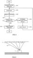
- FIG. 4 is a flowchart of an example of the control in accordance with an existing art. The details are as follows. Described here is an example of the control such that the control device controls the trolley and the hoisting device to transport a payload.
- the control device first prohibits a hoisting operation (S101). Next, the control device instructs the hoisting device to wind up the rope into a taut and slackless state (S102). The control device detects the rope length as a state value ⁇ with an encoder attached on the hoisting device (S103).
- Step S104 the control device performs termination determination based on the state value ⁇ .
- the termination condition is that the variation in rope length is smaller than a predetermined value or that the rope length changes from decreasing to increasing. If the termination condition is not satisfied, the control device proceeds to Step S105 and if satisfied, proceeds to Step S107.
- Step S105 the control device determines the direction to move the trolley. It determines the direction to decrease the rope length to be the direction to move (transversally) the trolley.
- Step S106 the control device moves the trolley in the direction determined by the control device at the foregoing Step S105 by a predetermined distance. After the trolley has moved, the control device returns to Step S102 and repeats the above-described processing.
- Step S107 the control device determines whether the termination condition is satisfied and the trolley has moved to directly above the payload and permits a hoisting operation to the operator.
- FIG. 5 illustrates the movement of the crane 1 in accordance with the existing art.
- the existing art moves the trolly 4 asymptotically to directly above the payload 9 by repeating straining the rope 6 by winding up, measuring the rope length, and slightly moving the trolly 4.
- FIG. 6 illustrates the relation among the positions of the trolley 4 and the payload 9 and the rope length.
- D be the positional deviation of the trolley 4 from the payload 9 in a horizontal direction
- H be the height from the payload 9 to the trolley 4
- FIG. 7 is a graph representing the relation between the positional deviation D and the rope length L obtained from Expression 1.
- FIG. 7 indicates that the variation of the rope length L becomes smaller and the travel distance of the trolley 4 required to detect variation of the rope length L becomes longer as the positional deviation D becomes smaller.
- the rope length L can be detected by the encoder 5a and let ⁇ L be the detection resolution of the encoder 5a for the rope length L.
- the minimum value Dmin for the positional deviation D depends on the detection resolution of the encoder 5a and reducing the positional deviation D has a limit.
- FIG. 8 is a graph representing the relation between the rope length L and the trolly position x for illustrating the principle of this invention.
- FIG. 9 is a diagram illustrating the movement of the crane 1 in this invention.
- the payload location xp is the position of the trolley 4 where the rope length L takes a minimum value when the trolley 4 is moved transversely (along the girder 3) and is the location (payload location) xp of the payload 9 in the transverse direction.
- the squared value of the rope length L(i) can be expressed by a quadratic function of the trolley position x(i).
- the control device 100 in this embodiment moves the trolley 4 transversely and measures at least two different trolley positions x(i) and the rope lengths L(i) of the taut rope there as state values and fits the acquired trolley positions x(i) and rope lengths L(i) to the foregoing Expression (5) by a well-known or publicly known method such as the method of least squares to calculate the parameters p1 and p2.
- the fitting in this embodiment obtains the best curve (the foregoing expression (5)) that fits the measured data by curve fitting or curve regression.
- control device 100 measures at least two different girder positions y(i) in its traveling direction and the rope length L(i) there to calculate the payload location yp of the payload 9 in the traveling direction where the rope length L from the trolley 4 takes the minimum value in the traveling direction of the girder 3, like the payload location xp.
- the control device 100 can reduce the horizontal positional deviation D of the trolley 4 from the payload 9 by moving the trolley 4 in the transverse direction and the traveling direction to the calculated payload location (xp, yp) and as a result, the initial sway is reduced.
- the method of this invention fits the rope lengths L(i) and the trolley positions x(i) to the quadratic curve expressed by the foregoing Expression (5).
- This method can determine the position directly above the payload 9 more precisely than the existing art that depends on the detection resolution of the encoder, achieving a smaller positional deviation D.
- the method of this invention requires at least two times of operation of straining the rope 6 by winding up, measuring the rope length L, and moving the trolley 4 in each of the transverse direction and the traveling direction.
- the number of repeats is smaller than the existing art, achieving a shorter operating time.
- FIG. 10 is a flowchart of an example of processing to be performed in the control device 100 of this invention. This processing starts based on the operator's instruction. The details are as follows.
- the control device 100 changes the operation mode to an initial positioning mode in this invention to move the trolley before hoisting a grounded payload.
- the operation input device 200 can have an operation mode selection switch and the operator operates the switch to change the operation mode.
- the control device 100 may display the operation mode with the display device 210 or the crane 1 can have a lamp for indicating the operation mode so that the surroundings can know the selected operation mode.
- Step S202 the control device 100 moves the trolley 4 to identify the payload location xp in the transverse direction. The details of this control will be described later.
- Step S203 the control device 100 moves the girder 3 along the runways 2 to identify the payload location yp in the traveling direction of the girder 3.
- Step S204 the control device 100 moves the trolley and the girder 3 to the identified payload location (xp, yp). As a result, the rope 6 drooping from the trolley 4 is positioned directly above the payload 9.
- the control device 100 changes the operation mode to a normal operation mode in which the crane 1 transports the payload 9 in the direction corresponding to the pressed operation button 202 of the operation terminal 201.
- This mode change can be performed not only in response to an explicit operation such as operating the operation mode selection switch of the operation terminal 201 but also automatically as soon as the trolley 4 reaches the payload location (xp, yp).
- the trolley 4 can be configured to move only when an operation button 202 of the operation terminal 201 is being pressed in the above-described Steps S202, S203, and S204.
- FIG. 11 is a flowchart of the details of identifying the payload location xp at Step S202 in FIG. 10 .
- the details are as follows.
- the details of Step S203 are the same as those of Step S202 in which the transverse direction in the following description is replaced by the traveling direction.
- Step S301 the control device 100 winds up the rope 6 until it becomes taut at the initial position x(1) of the trolley 4 and measures the rope length L(1) when the rope 6 is taut from the detection value of the encoder 5a.
- Whether the rope 6 is taut can be determined by a well-known or publicly-known technique, for example, by determining whether the current value of the hoist motor is higher than a threshold value or by determining whether the tension of the rope 6 is higher than a threshold value with a tension sensor attached to the rope 6.
- the control device 100 moves the trolley 4 to a trolley position x(2) that is distant from the trolley position x(1) by a predetermined distance dx, winds up the rope 6 at the position x(2) until the rope becomes taut, and measures the rope length L(2) with the encoder 5a.
- the horizontal position of the trolley 4 can be calculated from the moving time of the trolley 4 or measured with a laser distance sensor attached on the trolley 4.
- the control device 100 performs the foregoing Steps S301 and S302 with respect to the traveling direction of the girder 3 in the same way; specifically, the control device 100 moves the girder 3 to a girder position y(2) that is distant from the initial girder position y(1) by a predetermined distance dy, winds up the rope 6 at the position y(2) until the rope 6 becomes taut, and measures the rope length L(2) with the encoder 5a.
- the control device 100 fits the trolley positions and rope lengths (x(1), L(1)) and (x(2), L(2)) measured at the foregoing Steps S301 and S302 to the aforementioned Expression (5) by a well-known or publicly-known method such as the method of least squares to identify the parameters p1 and p2 in the traversing direction of the trolley 4.
- the control device 100 further identifies the parameters p1 and p2 in the traveling direction of the girder 3 by the same method as described above, or by fitting the girder positions and rope lengths (y(1), L(1)) and (y(2), L(2)) to the aforementioned Expression (5) by a well-known or publicly-known method such as the method of least squares.
- the control device 100 determines the payload location xp in the transverse direction where the rope length L (state value) takes a minimum value using the aforementioned Expression (6) with the parameter in the traversing direction of the trolley 4 denoted by p1x in FIG. 11 . Further, the control device 100 determines the payload location yp in the traveling direction where the rope length L takes a minimum value using the aforementioned Expression (6) with the parameter in the traveling direction of the girder 3 denoted by ply in FIG. 11 .
- Step S302 if the trolley 4 is moved in the state where the rope 6 is taut, the payload 9 may be dragged. Accordingly, the rope 6 should be paid out before moving the trolley 4. The same applies to moving the girder 3 in the traveling direction.
- the location of the payload 9 can be determined more precisely by fitting the trolley positions x(1) and x(2) and the lengths L(1) and L(2) of the taut rope to the quadratic curve in FIG. 8 , so that a smaller positional deviation is attained.
- This embodiment requires straining the rope 6 by the hoisting device 5 winding up, measuring the rope length L, and moving the trolley 4 (or the girder 3) for at least two times in each of the transverse direction and the traveling direction, achieving a smaller number of repeats. Accordingly, the operating time of the trolley 4 before hoisting the grounded payload can be reduced, enabling the hoisting operation to start sooner.
- This wire length Lw enables automatic acquisition of the distance L from the trolley 4 to the payload 9 by being added to the length Lr of the rope 6 from the trolley 4 to the hook 7 detected with the encoder 5a.
- This distance L is the same as the aforementioned rope length L from the trolley 4 to the payload 9.
- This distance L is a parameter necessary for the control to suppress the payload sway occurring in transporting a suspended payload 9.
- the payload sway in transportation is generated by an inertia force caused by acceleration or deceleration of the trolley 4 and acting on the suspended payload 9.
- This payload sway can be suppressed by payload sway suppression control to remove the frequency component of angular frequency ⁇ r from the speed command value for the trolley 4, as provided in WO 2018/211739 A (hereinafter, the known art), for example.
- this known art predetermines the wire length Lw or reads out a recorded value; it does not disclose a method of automatically acquiring the wire length Lw depending on the wires 8 in use.
- the foregoing calculation enables automatic acquisition of the wire length Lw, improving the performance to suppress the payload sway in transporting a payload.
- the foregoing calculation also enables automatic acquisition of the height H from the payload 9 to the trolley 4.
- the limit in unwinding (paying out) the rope 6 can be automatically determined; the payload can prevent inadvertent impact onto the ground or unhook from slack wires caused by excessive unwinding, increasing the safeness of the crane 1.
- Embodiment 2 Described next is a crane 1 in Embodiment 2 of this invention.
- the repetitive description of the points in common with the foregoing embodiment is omitted here.
- the configurations of the crane 1 and the control device 100 are the same as those in Embodiment 1.
- the crane 1 in Embodiment 1 identifies the payload location using the distance between the trolley 4 and the payload 9 (the length of the rope 6 including the length of the wires 8) as a state value.
- a hook 7 is attached at the end of the rope 6 drooping from the trolley 4 to hang the payload 9 with the wires 8, as illustrated in FIG. 1 .
- the crane 1 does not usually equip a device for directly detecting the distance from the hook 7 to the payload 9 or the length of the wires 8. Accordingly, this embodiment regards the length of the wires 8 as an unknown to identify the payload location xp (yp).
- control device 100 measures at least three different girder positions y(i) in the traveling direction and the rope lengths Lr(i) there. Then, the control device 100 can calculate the payload location yp of the payload 9 in the traveling direction where the rope length Lr takes a minimum value when the girder 3 is moved in the traveling direction.
- the control device 100 can eliminate the horizontal positional deviations of the trolley 4 and the girder 3 from the payload 9 by moving the trolley 4 and the girder 3 to the calculated payload location (xp, yp) and as a result, the initial sway is reduced.
- the above-described method enables the location of the payload 9 to be identified, even if the distance from the hook 7 to the payload 9 or the wire length Lw is unknown.
- the above-described method enables automatic acquisition of the wire length Lw, which improves the payload sway suppression control in transporting a payload. Further, automatic acquisition of the height H is also available; the safeness of the crane 1 can be increased by automatically determining the limit in unwinding the rope 6.
- FIG. 14 illustrates a configuration of the control device of the crane 1 in Embodiment 3.
- the configurations same as those in the foregoing Embodiment 1 are assigned same reference signs and repetitive description thereof is omitted here.
- FIG. 14 includes a force sensor 4a (fourth sensor) on the trolley 4 to detect the force transversely acting on the trolley 4, a tension sensor 5b (third sensor) on the hoisting device 5 to detect the tension of the rope 6, and a sway angle sensor 7a (second sensor) on the hook 7 to detect the angle of the rope 6, in addition to the configuration in the foregoing Embodiment 1.
- the control device 100 additionally includes a horizontal force detector 301 (another implementation means of the fourth sensor) for detecting the transversal force applied to the trolley 4 and a tension detector 311 (another implementation means of the third sensor) for measuring the tension of the rope 6.
- FIG. 12 illustrates the movement of the crane 1 in Embodiment 3.
- the crane 1 in this Embodiment 3 detects the angle (rope sway angle) of the rope 6 in a taut state with respect to the vertical direction of the trolley 4 with the sway angle sensor 7a and uses the rope sway angle as a state value to identify the payload location.
- the rope sway angle can be detected with the encoder by detecting the angle of a weight hanging from the hook 7 as described in the aforementioned Patent Document 1 or with a gyrosensor attached on the hook 7.
- the control device 100 transversely moves the trolley 4 and measures at least two different trolley positions x(i) and the rope sway angles ⁇ (i) there and fits the acquired trolley positions x(i) and rope sway angles ⁇ (i) to the foregoing Expression (16) by the method of least squares to calculate the parameters p1 and p2.
- control device 100 measures at least two different girder positions y(i) in the traveling direction of the girder 3 and the rope sway angles ⁇ (i) there. Then, the control device 100 can calculate the payload location yp of the payload 9 in the traveling direction where the rope sway angle takes a minimum value when the girder 3 is moved in the traveling direction.
- the acquired location (xp, yp) is the location of the payload; the control device 100 can eliminate the horizontal positional deviations of the trolley 4 and the girder 3 from the payload 9 by moving the trolley 4 and the girder 3 to this calculated payload location, and as a result, the initial sway is reduced.
- the above-described method enables the location of the payload 9 to be identified, using the sway angle ⁇ of a taut rope 6 as a state value.
- the above-described method enables automatic acquisition of the wire length Lw, which improves the payload sway suppression control in transporting a payload. Further, automatic acquisition of the height H is also available; the safeness of the crane 1 can be increased by automatically determining the limit in unwinding the rope 6.
- Embodiment 4 Described next is a crane 1 in Embodiment 4 of this invention.
- the repetitive description of the points in common with the foregoing embodiments is omitted here.
- the configurations of the crane 1 and the control device 100 are the same as those in Embodiment 3 illustrated in FIG. 14 .
- FIG. 13 illustrates the movement of the crane 1 in Embodiment 4.
- the crane 1 in this embodiment uses the tension of the taut rope 6 and the force horizontally acting on the trolley 4 as state values to identify the payload location.
- the tension of the rope 6 can be detected by the tension sensor 5b attached on the hoisting device 5 or the tension detector 311 that calculates the tension of the rope 6 from the current value of the hoist motor acquired from the hoist motor controller 310.
- the force horizontally acting on the trolley 4 can be detected by the force sensor 4a or the horizontal force detector 301 that detects the motor current when the trolley 4 keeps a horizontal position in a transverse direction.
- the control device 100 transversely moves the trolley 4 and measures at least two different trolley positions x(i) and the tensions T(i) of the rope 6 and the forces F(i) horizontally acting on the trolley 4 there and fits the acquired trolley positions x(i), tensions T(i), and forces F(i) to the foregoing Expression (21) by the method of least squares to calculate the parameters p1 and p2.
- control device 100 measures at least two different girder positions y(i) in the traveling direction of the girder 3 and the tensions T(i) of the rope 6 and the forces F(i) horizontally acting on the trolley 4 there to calculate the payload location yp of the payload 9 in the traveling direction where the rope sway angle ⁇ (i) takes a minimum value when the girder 3 is moved in the traveling direction.
- the control device 100 can eliminate the horizontal positional deviations of the trolley 4 and the girder 3 from the payload 9 by moving the trolley 4 and the girder 3 to the calculated payload location (xp, yp), and as a result, the initial sway is reduced.
- the above-described method enables the location of the payload 9 to be identified, using the tension of the rope 6 and the force horizontally acting on the trolley 4 as state values.
- the crane 1 in this Modified Example 4 can also identify the wire length Lw and the height H in the same way as the crane 1 in Modified Example 3. Automatic acquisition of the wire length Lw enables improvement in payload sway suppression control in transporting a payload and automatic acquisition of the height H enables increase in safeness of the crane 1 because automatic determination of the limit in unwinding the rope 6 is available.
- Embodiment 5 Described next is a crane 1 in Embodiment 5 of this invention.
- the repetitive description of the points in common with the foregoing embodiments is omitted here.
- the configurations of the crane 1 and the control device 100 are the same as those in Embodiment 3 illustrated in FIG. 14 .
- the crane 1 in Embodiment 5 pays out the rope 6 before moving the trolley 4 to prevent the payload 9 from being lifted or dragged, in the case where the payload 9 is grounded.
- the control device 100 uses the time taken to wind up the rope 6 from the paid-out state to a taut state as a state value to identify the payload location.
- Lf(i) be the paid-out length of the rope 6
- Tf(i) be the time taken to wind up the rope 6 into a taut state
- V be the winding speed
- L0 be the rope length when the rope 6 is first wounded up to a taut state
- x(i) be the position of the trolley 4
- xp be the location of the payload 9, these have relations expressed by Expressions (23) and (24) below.
- the winding speed V can be calculated by the control device 100 from the time Tf taken to wind up the rope 6 into a taut state and the variation of the rope length L0 when the rope 6 is wounded to the taut state.
- the time Tf taken to wind up the rope 6 into a taut state can be measured with a timer included in the control device 100.
- the rope length L0 can be measured with the encoder 5a, like in the above-described Embodiment 1.
- control device 100 measures at least three different girder positions y(i) in the traveling direction of the girder 3 and the lengths Lf(i) of the rope 6 paid out before moving the girder 3 and the times Tf(i) taken to wind up the rope into a taut state there to calculate the payload location yp of the payload 9 in the traveling direction where dL takes a maximum value when the girder 3 is moved in the traveling direction.
- the control device 100 can eliminate the horizontal positional deviations of the trolley 4 and the girder 3 from the payload 9 by moving the trolley 4 and the girder 3 to the calculated payload location (xp, yp), and as a result, the initial sway is reduced.
- the above-described method enables the location of the payload 9 to be identified, using the length of the rope 6 paid out before moving the trolley 4 and the time taken to wind up the rope 6 into a taut state as state values.
- the above-described method enables automatic acquisition of the wire length Lw, which improves the payload sway suppression control in transporting a payload. Further, automatic acquisition of the height H is also available; the safeness of the crane 1 can be increased by automatically determining the limit in unwinding the rope 6.
- this invention is generally effective for cranes 1 capable of horizontally transporting a payload 9 and is applicable to not only a crane 1 (such as an overhead crane) for transporting a payload in the transverse direction and the traveling direction with a trolley 4 and a girder 3 but also a crane (such as an unloader) for transporting a load only in either the transverse direction or the traveling direction. That is to say, the term "crane" referred to in the subsequent description includes any kinds of cranes capable of horizontally transporting a payload 9.
- the payload (hooked payload) to be transported by the crane 1 is hung by a rope 6 or a chain in transportation.
- the hanging member (or sling member) used in this invention is not limited to a specific one, even in terms of its material or shape, as far as it can be used to hang a payload.
- rope is used as a generic term for referring to a hanging member (sling member) for hanging a payload, as already stated. That is to say, the term “rope” includes not only a so-called rope but also chain, belt, wire, cable, band, cord, and the like.
- the above-described configuration enables the control device 100 to automatically acquire the wire length Lw, improving the payload sway suppression control in transporting a payload.
- Some of all of the components, functions, processing units, and processing means described above may be implemented by hardware by, for example, designing the components, the functions, and the like as an integrated circuit.
- the components, functions, and the like described above may also be implemented by software by a processor interpreting and executing programs that implement their respective functions.
- Programs, tables, files, and other types of information for implementing the functions can be put in a memory, in a storage apparatus such as a hard disk, or a solid state drive (SSD), or on a recording medium such as an IC card, an SD card, or a DVD.
- SSD solid state drive
- control lines and information lines described are lines that are deemed necessary for the description of this invention, and not all of control lines and information lines of a product are mentioned. In actuality, it can be considered that almost all components are coupled to one another.
Landscapes
- Engineering & Computer Science (AREA)
- Mechanical Engineering (AREA)
- Control And Safety Of Cranes (AREA)
Abstract
Description
- The present application claims priority from Japanese patent application
JP 2021-55350 filed on March 29, 2021 - This invention relates to a crane for hanging and transporting a payload and a method of controlling the crane.
- In recent years, aging of skilled crane operators and increasing installation of cranes have caused labor shortage; inexperienced and unskilled workers more often operate cranes. Unskilled workers are especially not good at steadying operation to suppress sway of the payload (payload sway). Payload sway generates high risks of accidents such as collision with and press by the payload. Furthermore, it takes a long time to be stopped, which increases the working time. Accordingly, a technique for automatically suppressing the payload sway is demanded to increase the safeness and work efficiency.
- In hoisting a grounded payload, if the horizontal transport device (trolley) carrying the payload with a rope has a horizontal positional deviation from the payload, the payload may start pendular movement at the moment when the payload leaves the ground, causing payload sway (initial sway).
- To reduce this initial sway, a technique is disclosed in
Patent Document 1. The existing technique according toPatent Document 1 winds up the rope into a taut and slackless state before hoisting the payload, measures the length of the rope in the taut state, slightly moves the trolley in the direction to reduce the rope length, and repeats the foregoing operation until the trolley is positioned directly above the payload where the rope length is minimized and the positional deviation is eliminated. According toPatent Document 1, the condition to determine that the rope length is minimized is that the variation in rope length caused by move of the trolley has decreased to a predetermined small value or the variation in rope length changes from decreasing to increasing. -
- Patent Document 1:
JP 2019-119583 A - Patent Document 2:
WO 2018/211739 A -
Patent Document 1 determines whether the rope length is minimized with its variation. However, the variation in rope length becomes smaller as the positional deviation of the trolley from the payload becomes smaller and accordingly, the precision in detecting the position where the rope length is minimized has a limit, generating a limit in reducing the positional deviation. - Furthermore,
Patent Document 1 repeats straining the rope by winding up, measuring the rope length, and slightly moving the trolley and therefore, if the positional deviation is large, the operation has to be repeated for a large number of times. It takes a long time (operation time) to move the trolley to directly above the payload. - This invention is accomplished in view of these problems and aims to provide a crane and a method of controlling the crane that can hoist a grounded payload sooner by attaining a smaller horizontal positional deviation of the trolley from the payload in a shorter operating time of the trolley before the hoisting operation.
- One aspect of the present invention is a crane includes a horizontal transport device horizontally movable with a motor, a hoisting device mounted on the horizontal transport device, the hoisting device being capable of winding a rope with a hoist motor, a hook attached on the rope to hang a payload and a control unit including a processor and a memory, the control unit being configured to control the horizontal transport device and the hoisting device. The control unit includes a rope tension determination unit configured to determine whether the rope is in a taut state without a slack; a state measurement unit configured to measure at least one state value of the crane when the rope has been wound up into a taut state by the hoisting device being driven and
a transport control unit configured to move the horizontal transport device. The state measurement unit is configured to identify a payload location xp of a grounded payload, using a position x of the horizontal transport device and the at least one state value measured when the rope is in a taut state, and the transport control unit is configured to move the horizontal transport device to the identified payload location xp to position the rope directly above the payload. - This invention enables a crane to hoist a grounded payload sooner by attaining a smaller horizontal positional deviation of a trolley from the payload in a shorter operating time of the trolley before the hoisting operation.
- The details of at least one embodiment of a subject matter disclosed herein are set forth in the accompanying drawings and the following description. Other features, aspects, and effects of the disclosed subject matter become apparent from the following disclosure, drawings, and claims.
-
-
FIG. 1 illustrates a general configuration of an overhead crane in a first embodiment of this invention. -
FIG. 2 illustrates a configuration of the control device of the crane in the first embodiment of this invention. -
FIG. 3A illustrates the movement of the crane in hoisting a grounded payload in the first embodiment of this invention. -
FIG. 3B illustrates the movement of the crane in hoisting a grounded payload in the first embodiment of this invention. -
FIG. 4 is a flowchart of an example of the control in accordance with an existing art. -
FIG. 5 illustrates the movement of the crane in accordance with the existing art. -
FIG. 6 illustrates the relation among the positions of the trolley and the payload and the rope length in the first embodiment of this invention. -
FIG. 7 is a graph representing the relation between the positional deviation D and the rope length L obtained from Expression in the first embodiment of this invention. -
FIG. 8 is a graph representing the relation between the rope length L and the trolly position x for illustrating the principle of the first embodiment of this invention. this invention. -
FIG. 9 is a diagram illustrating the movement of the crane in the first embodiment of this invention. -
FIG. 10 is a flowchart of an example of processing to be performed in thecontrol device 100 of the first embodiment of this invention. -
FIG. 11 is a flowchart of the details of identifying the payload location in the first embodiment of this invention. -
FIG. 12 illustrates the movement of the crane in a third embodiment of this invention. -
FIG. 13 illustrates the movement of the crane in a fourth embodiment of this invention. -
FIG. 14 illustrates a configuration of the control device of the crane in the third and fourth embodiment of this invention. - Hereinafter, embodiments of this invention will be specifically described with reference to the drawings. However, this invention is not limited to the embodiments and the scope of this invention includes various modifications and applications within its technical concept.
- The configuration and operation of a
crane 1 inEmbodiment 1 of this invention are described. Throughout the drawings, the same apparatuses (devices and components) are denoted by the same reference signs and description about already described apparatuses may be skipped in the subsequent description. -
FIG. 1 illustrates a general configuration of an overhead crane. Thecrane 1 includesrunways 2 provided along the walls on opposite sides of a building such as a factory (not shown), agirder 3 that moves on the top sides of therunways 2, and atrolley 4 that moves along the underside of thegirder 3. - The
girder 3 and thetrolley 4 have wheels (not shown) to be driven by electric motors (not shown); thegirder 3 and thetrolley 4 can move with these wheels. Thegirder 3 travels along therunways 2 and thetrolley 4 moves along the underside of thegirder 3 transversely (horizontally: leftward and rightward inFIG. 1 ) between therunways 2. - The
trolley 4 is provided with a hoisting device (hoist) 5. The hoistingdevice 5 includes a drum (not shown) to be driven by an electric motor; this drum is rotated to wind or unwind arope 6, so that ahook 7 at the end of therope 6 is raised or lowered. - A
payload 9 is hooked on thehook 7 directly or throughwires 8; thepayload 9 is raised and lowered with up and down of thehook 7. Thecrane 1 can move thepayload 9 horizontally by horizontal movement (traveling) of thegirder 3 and horizontal movement (traversing) of thetrolley 4 and can move thepayload 9 vertically (up and down) with thehoisting device 5. - The sling member for hanging the
payload 9 from thehook 7 is not limited to thewires 8; other kinds of slings such as chain and rope can be employed. - In
FIG. 1 , thetrolley 4 and thegirder 3 correspond to horizontal transport devices. However, at least either one of thetrolley 4 and thegirder 3 can be referred to as horizontal transport device; otherwise, thetrolley 4 that moves along thegirder 3 can be referred to as a first horizontal transport device and thegirder 3 that moves along therunways 2 can be referred to as a second horizontal transport device. - The
hoisting device 5 includes anencoder 5a (seeFIG. 2 ) for detecting the rotation angle of the drum to measure the length of the rope 6 (rope length) paid out from the drum. -
FIG. 2 illustrates a configuration of the control device of thecrane 1 in this embodiment. For simplicity of description,FIG. 2 illustrates traverse control for thetrolley 4 and up and down control for thehoisting device 5 and excludes travel control for thegirder 3. -
FIG. 2 also does not include driving members such as electric motors. Thecontrol device 100 of thecrane 1 includes an arithmetic and control unit, atraverse motor controller 300 for controlling the electric motor (traverse motor) of thetrolley 4, a hoistmotor controller 310 for controlling the electric motor (hoist motor) of thehoisting device 5, anoperation input device 200, and adisplay device 210. Although not shown inFIG. 2 , thecontrol device 100 includes a travel motor controller for controlling the electric motor (travel motor) to drive thegirder 3 along therunways 2. - The
control device 100 calculates and outputs speed command values for thetrolley 4 and thehoisting device 5 and outputs information to thedisplay device 210, based on the operation command input through theoperation input device 200 and information acquired from sensors including theencoder 5a (first sensor). - The arithmetic and control unit in the
control device 100 is commonly a general-purpose computer; it includes a micro-processing unit (MPU) 101 for performing control and arithmetic operation using installed programs and data, amemory 102 for storing the programs and data, and an input/output control unit 103 for inputting data and signals from the external and outputting signals arithmetically processed by theMPU 101 to the external. TheMPU 101, thememory 102, and the input/output control unit 103 are connected by abus line 104 for transmitting signals and data. - The
operation input device 200 is connected to anoperation terminal 201 to be operated by the operator of thecrane 1. Theoperation terminal 201 hasoperation buttons 202 associated with transport directions of the payload: forward, backward, rightward, leftward, upward, and downward. - The
display device 210 displays information such as the state of thecrane 1. Theoperation terminal 201 can be connected to thecontrol device 100 with wire or wirelessly. Thedisplay device 210 can be mounted on the same housing as theoperation terminal 201. - The
traverse motor controller 300 and the hoistmotor controller 310 control the electric motors of thetrolley 4 and thehoisting device 5 in accordance with the speed command values output from thecontrol device 100. AlthoughFIG. 2 does not illustrate specific configurations of thetraverse motor controller 300 and the hoistmotor controller 310, they can be configured with general-use computers like thecontrol device 100 or inverter circuits. Thetraverse motor controller 300 and the hoistmotor controller 310 can be mounted on the same housing as thecontrol device 100. - Although not shown in
FIG. 2 , thecontrol device 100 further outputs a speed command value for thegirder 3, in addition to the speed command values for thetrolley 4 andhoisting device 5. As for thegirder 3, a not-shown electric motor (travel motor) controller controls an electric motor in accordance with this speed command value. - The
memory 102 includes a ropetension determination unit 21, astate measurement unit 22, a hoistingcontrol unit 23, and atransport control unit 24, which are programs loaded and executed by theMPU 101. - The
MPU 101 performs processing in accordance with the programs of function units to work as the function units for providing predetermined functions. For example, theMPU 101 performs processing in accordance with the rope tension determination program to function as the ropetension determination unit 21. The same applies to the other programs. Furthermore, theMPU 101 works as function units for providing functions of a plurality of processes executed by a program. A computer and a computer system are an apparatus and a system including these function units. - The rope
tension determination unit 21 determines whether therope 6 is in a taut and slackless state based on the current value of the electric motor of thehoisting device 5. Thestate measurement unit 22 measures the state values such as the rope length and the positions of thetrolley 4 and thegirder 3 after winding up therope 6 connected to a grounded payload into a taut state, infers the location of the payload from the state values, and positions thecrane 1 by moving thetrolley 4 and thegirder 3 so that therope 6 is positioned directly above thepayload 9. - The
transport control unit 24 receives command values from theoperation terminal 201 and the payload location from thestate measurement unit 22 and drives thetrolley 4 and thegirder 3 with thetraverse motor controller 300 and a not-shown travel motor controller, respectively, to horizontally move thetrolley 4 and thegirder 3. - The hoisting
control unit 23 outputs command values to the hoistmotor controller 310 in accordance with the command values from theoperation terminal 201 and thestate measurement unit 22. - In hoisting a grounded
payload 9, payload sway (initial sway) may occur when thepayload 9 leaves the ground (or the floor).FIGS. 3A and 3B illustrate the movement of thecrane 1 in hoisting a groundedpayload 9. If thetrolley 4 has a positional deviation D from the groundedpayload 9 in a horizontal direction as illustrated inFIG. 3A , thepayload 9 starts pendular movement with an amplitude D (positional deviation D) and an angular frequency (g/L)1/2 (L: the distance from thetrolley 4 to thepayload 9, g: the acceleration of gravity) when therope 6 is wound and thepayload 9 leaves the ground as illustrated inFIG. 3B . This is the initial sway. - To reduce this initial sway, the horizontal positional deviation of the
trolley 4 from thepayload 9 when thepayload 9 leaves the ground should be reduced and accordingly, thetrolley 4 should be moved to directly above thepayload 9 before hoisting thepayload 9. To satisfy this condition, there exists an art disclosed in theaforementioned Patent Document 1. - This existing art winds up the rope into a taut and slackless state before hoisting the payload, measures the length of the rope in the taut state, slightly moves the trolley in the direction to reduce the rope length, and repeats the foregoing operation until the trolley is positioned directly above the payload where the rope length is minimized and the positional deviation is eliminated.
- According to
Patent Document 1, the condition to determine that the rope length is minimized is that the variation in rope length caused by the movement of the trolley has decreased to a predetermined small value or the variation in rope length changes from decreasing to increasing. -
FIG. 4 is a flowchart of an example of the control in accordance with an existing art. The details are as follows. Described here is an example of the control such that the control device controls the trolley and the hoisting device to transport a payload. - The control device first prohibits a hoisting operation (S101). Next, the control device instructs the hoisting device to wind up the rope into a taut and slackless state (S102). The control device detects the rope length as a state value ψ with an encoder attached on the hoisting device (S103).
- At Step S104, the control device performs termination determination based on the state value ψ. The termination condition is that the variation in rope length is smaller than a predetermined value or that the rope length changes from decreasing to increasing. If the termination condition is not satisfied, the control device proceeds to Step S105 and if satisfied, proceeds to Step S107.
- At Step S105, the control device determines the direction to move the trolley. It determines the direction to decrease the rope length to be the direction to move (transversally) the trolley. At Step S106, the control device moves the trolley in the direction determined by the control device at the foregoing Step S105 by a predetermined distance. After the trolley has moved, the control device returns to Step S102 and repeats the above-described processing.
- At Step S107, the control device determines whether the termination condition is satisfied and the trolley has moved to directly above the payload and permits a hoisting operation to the operator.
-
FIG. 5 illustrates the movement of thecrane 1 in accordance with the existing art. The existing art moves thetrolly 4 asymptotically to directly above thepayload 9 by repeating straining therope 6 by winding up, measuring the rope length, and slightly moving thetrolly 4. - This existing art has raised two issues. One of them is the limit of reducing the positional deviation because of the precision in detection of the rope length.
FIG. 6 illustrates the relation among the positions of thetrolley 4 and thepayload 9 and the rope length. Letting D be the positional deviation of thetrolley 4 from thepayload 9 in a horizontal direction and H be the height from thepayload 9 to thetrolley 4, the distance from thetrolley 4 to thepayload 9 or the length L of therope 6 including the length of thewires 8 can be expressed by the following Expression (1):
[Expression 1]
-
FIG. 7 is a graph representing the relation between the positional deviation D and the rope length L obtained fromExpression 1.FIG. 7 indicates that the variation of the rope length L becomes smaller and the travel distance of thetrolley 4 required to detect variation of the rope length L becomes longer as the positional deviation D becomes smaller. The rope length L can be detected by theencoder 5a and let ΔL be the detection resolution of theencoder 5a for the rope length L. The minimum value Dmin for the positional deviation D can be expressed by the following Expression (2):
[Expression 2]
- As understood from the above description, the minimum value Dmin for the positional deviation D depends on the detection resolution of the
encoder 5a and reducing the positional deviation D has a limit. - Another issue is that the operating time to move the
trolly 4 to directly above thepayload 9 is long when the positional deviation D is large. As illustrated inFIG. 4 , the existing art repeats straining the rope by winding up, measuring the rope length, and slightly moving thetrolley 4. For this reason, when the positional deviation D is large, more repeats are required, increasing the operating time. - This invention addresses the above-described issues as follows.
FIG. 8 is a graph representing the relation between the rope length L and the trolly position x for illustrating the principle of this invention.FIG. 9 is a diagram illustrating the movement of thecrane 1 in this invention. The trolley position x(i) in the traversing direction of thetrolley 4 and the distance L(i) between thetrolley 4 at the position x(i) and the payload 9 (the length of the taut rope including the length of the wires 8) have the relation expressed by the following Expression (3):
[Expression 3]
- In
FIG. 8 , the payload location xp is the position of thetrolley 4 where the rope length L takes a minimum value when thetrolley 4 is moved transversely (along the girder 3) and is the location (payload location) xp of thepayload 9 in the transverse direction. The following Expression (4) can be obtained by squaring the both members of the Expression (3):
[Expression 4]
- Letting p1 and p2 be the parameters including the height H from the
payload 9 to the trolley 4 (or the hoisting device 5) and the payload location xp, the foregoing Expression (4) can be expressed by the following Expression (5):
[Expression 5]
- As expressed by Expression (5), the squared value of the rope length L(i) can be expressed by a quadratic function of the trolley position x(i). Hence, the
control device 100 in this embodiment moves thetrolley 4 transversely and measures at least two different trolley positions x(i) and the rope lengths L(i) of the taut rope there as state values and fits the acquired trolley positions x(i) and rope lengths L(i) to the foregoing Expression (5) by a well-known or publicly known method such as the method of least squares to calculate the parameters p1 and p2. The fitting in this embodiment obtains the best curve (the foregoing expression (5)) that fits the measured data by curve fitting or curve regression. - The
control device 100 can calculate the payload location xp of thepayload 9 in the transverse direction, using the following Expression (6) with the calculated parameters p1 and p2:
[Expression 6]
- In similar, the
control device 100 measures at least two different girder positions y(i) in its traveling direction and the rope length L(i) there to calculate the payload location yp of thepayload 9 in the traveling direction where the rope length L from thetrolley 4 takes the minimum value in the traveling direction of thegirder 3, like the payload location xp. - The
control device 100 can reduce the horizontal positional deviation D of thetrolley 4 from thepayload 9 by moving thetrolley 4 in the transverse direction and the traveling direction to the calculated payload location (xp, yp) and as a result, the initial sway is reduced. - As described above, the method of this invention fits the rope lengths L(i) and the trolley positions x(i) to the quadratic curve expressed by the foregoing Expression (5). This method can determine the position directly above the
payload 9 more precisely than the existing art that depends on the detection resolution of the encoder, achieving a smaller positional deviation D. - Furthermore, the method of this invention requires at least two times of operation of straining the
rope 6 by winding up, measuring the rope length L, and moving thetrolley 4 in each of the transverse direction and the traveling direction. The number of repeats is smaller than the existing art, achieving a shorter operating time. -
FIG. 10 is a flowchart of an example of processing to be performed in thecontrol device 100 of this invention. This processing starts based on the operator's instruction. The details are as follows. - At Step S201, the
control device 100 changes the operation mode to an initial positioning mode in this invention to move the trolley before hoisting a grounded payload. For example, theoperation input device 200 can have an operation mode selection switch and the operator operates the switch to change the operation mode. - The
control device 100 may display the operation mode with thedisplay device 210 or thecrane 1 can have a lamp for indicating the operation mode so that the surroundings can know the selected operation mode. - At Step S202, the
control device 100 moves thetrolley 4 to identify the payload location xp in the transverse direction. The details of this control will be described later. At Step S203, thecontrol device 100 moves thegirder 3 along therunways 2 to identify the payload location yp in the traveling direction of thegirder 3. - At Step S204, the
control device 100 moves the trolley and thegirder 3 to the identified payload location (xp, yp). As a result, therope 6 drooping from thetrolley 4 is positioned directly above thepayload 9. - At Step S205, the
control device 100 changes the operation mode to a normal operation mode in which thecrane 1 transports thepayload 9 in the direction corresponding to the pressedoperation button 202 of theoperation terminal 201. This mode change can be performed not only in response to an explicit operation such as operating the operation mode selection switch of theoperation terminal 201 but also automatically as soon as thetrolley 4 reaches the payload location (xp, yp). - To ensure the safeness, the
trolley 4 can be configured to move only when anoperation button 202 of theoperation terminal 201 is being pressed in the above-described Steps S202, S203, and S204. -
FIG. 11 is a flowchart of the details of identifying the payload location xp at Step S202 inFIG. 10 . The details are as follows. The details of Step S203 are the same as those of Step S202 in which the transverse direction in the following description is replaced by the traveling direction. - At Step S301, the
control device 100 winds up therope 6 until it becomes taut at the initial position x(1) of thetrolley 4 and measures the rope length L(1) when therope 6 is taut from the detection value of theencoder 5a. - Whether the
rope 6 is taut can be determined by a well-known or publicly-known technique, for example, by determining whether the current value of the hoist motor is higher than a threshold value or by determining whether the tension of therope 6 is higher than a threshold value with a tension sensor attached to therope 6. - At Step S302, the
control device 100 moves thetrolley 4 to a trolley position x(2) that is distant from the trolley position x(1) by a predetermined distance dx, winds up therope 6 at the position x(2) until the rope becomes taut, and measures the rope length L(2) with theencoder 5a. The horizontal position of thetrolley 4 can be calculated from the moving time of thetrolley 4 or measured with a laser distance sensor attached on thetrolley 4. - The
control device 100 performs the foregoing Steps S301 and S302 with respect to the traveling direction of thegirder 3 in the same way; specifically, thecontrol device 100 moves thegirder 3 to a girder position y(2) that is distant from the initial girder position y(1) by a predetermined distance dy, winds up therope 6 at the position y(2) until therope 6 becomes taut, and measures the rope length L(2) with theencoder 5a. - At Step S303, the
control device 100 fits the trolley positions and rope lengths (x(1), L(1)) and (x(2), L(2)) measured at the foregoing Steps S301 and S302 to the aforementioned Expression (5) by a well-known or publicly-known method such as the method of least squares to identify the parameters p1 and p2 in the traversing direction of thetrolley 4. - The
control device 100 further identifies the parameters p1 and p2 in the traveling direction of thegirder 3 by the same method as described above, or by fitting the girder positions and rope lengths (y(1), L(1)) and (y(2), L(2)) to the aforementioned Expression (5) by a well-known or publicly-known method such as the method of least squares. - At Step S304, the
control device 100 determines the payload location xp in the transverse direction where the rope length L (state value) takes a minimum value using the aforementioned Expression (6) with the parameter in the traversing direction of thetrolley 4 denoted by p1x inFIG. 11 . Further, thecontrol device 100 determines the payload location yp in the traveling direction where the rope length L takes a minimum value using the aforementioned Expression (6) with the parameter in the traveling direction of thegirder 3 denoted by ply inFIG. 11 . - At the aforementioned Step S302, if the
trolley 4 is moved in the state where therope 6 is taut, thepayload 9 may be dragged. Accordingly, therope 6 should be paid out before moving thetrolley 4. The same applies to moving thegirder 3 in the traveling direction. - Although this example moves the trolley transversally to measure the rope length at two positions, the positions to measure the rope length can be increased for higher accuracy in detecting the payload location xp.
- As described above, the location of the
payload 9 can be determined more precisely by fitting the trolley positions x(1) and x(2) and the lengths L(1) and L(2) of the taut rope to the quadratic curve inFIG. 8 , so that a smaller positional deviation is attained. - This embodiment requires straining the
rope 6 by thehoisting device 5 winding up, measuring the rope length L, and moving the trolley 4 (or the girder 3) for at least two times in each of the transverse direction and the traveling direction, achieving a smaller number of repeats. Accordingly, the operating time of thetrolley 4 before hoisting the grounded payload can be reduced, enabling the hoisting operation to start sooner. - Focusing on the constant terms of the foregoing Expressions (4) and (5), the height H can be calculated by the following Expression (7):
[Expression 7]
- Subtracting the rope length Lr (x = xp) of the
taut rope 6 from thetrolley 4 positioned directly above thepayload 9 to thehook 7 from this height H provides the length Lw of thewires 8 from thehook 7 to thepayload 9 as expressed in the following Expression (8):
[Expression 8]
- The above expression enables automatic acquisition of the length Lw of the wires 8 (hereinafter wire length). This wire length Lw enables automatic acquisition of the distance L from the
trolley 4 to thepayload 9 by being added to the length Lr of therope 6 from thetrolley 4 to thehook 7 detected with theencoder 5a. This distance L is the same as the aforementioned rope length L from thetrolley 4 to thepayload 9. - This distance L is a parameter necessary for the control to suppress the payload sway occurring in transporting a suspended
payload 9. The payload sway in transportation is generated by an inertia force caused by acceleration or deceleration of thetrolley 4 and acting on the suspendedpayload 9. The inertia force exerts sway at an angular frequency ωr expressed as follows:

- This payload sway can be suppressed by payload sway suppression control to remove the frequency component of angular frequency ωr from the speed command value for the
trolley 4, as provided inWO 2018/211739 A (hereinafter, the known art), for example. - However, this known art predetermines the wire length Lw or reads out a recorded value; it does not disclose a method of automatically acquiring the wire length Lw depending on the
wires 8 in use. The foregoing calculation enables automatic acquisition of the wire length Lw, improving the performance to suppress the payload sway in transporting a payload. - The foregoing calculation also enables automatic acquisition of the height H from the
payload 9 to thetrolley 4. Hence, the limit in unwinding (paying out) therope 6 can be automatically determined; the payload can prevent inadvertent impact onto the ground or unhook from slack wires caused by excessive unwinding, increasing the safeness of thecrane 1. - Described next is a
crane 1 inEmbodiment 2 of this invention. The repetitive description of the points in common with the foregoing embodiment is omitted here. The configurations of thecrane 1 and thecontrol device 100 are the same as those inEmbodiment 1. - The
crane 1 inEmbodiment 1 identifies the payload location using the distance between thetrolley 4 and the payload 9 (the length of therope 6 including the length of the wires 8) as a state value. In this regard, ahook 7 is attached at the end of therope 6 drooping from thetrolley 4 to hang thepayload 9 with thewires 8, as illustrated inFIG. 1 . - Although the distance from the
trolley 4 to thehook 7 or the length of therope 6 can be detected with the encoder attached on thehoisting device 5, thecrane 1 does not usually equip a device for directly detecting the distance from thehook 7 to thepayload 9 or the length of thewires 8. Accordingly, this embodiment regards the length of thewires 8 as an unknown to identify the payload location xp (yp). - Letting Lr(i) be the rope length, Lw be the wire length, x(i) be the position of the
trolley 4, xp be the payload location, and H be the height from thepayload 9 to thetrolley 4, these have a relation as expressed by the following Expression (9):
[Expression 10]
- The following Expression (10) can be obtained by squaring the both members of Expression (9):
[Expression 11]
- Letting p1, p2, and p3 be the parameters including the wire length Lw, the height H, and the payload location xp, the following Expression (11) is obtained:
[Expression 12]
- The
control device 100 transversely moves thetrolley 4 and measures at least three different trolley positions x(i) and the rope lengths Lr(i) of thetaut rope 6 there and fits the acquired trolley positions x(i) and rope lengths Lr(i) to the foregoing Expression (11) by the method of least squares to calculate the parameters p1, p2, and p3. Then, the payload location xp of thepayload 9 in the transverse direction can be calculated by the following Expression (12) with the calculated parameters:
[Expression 13]
- In similar, the
control device 100 measures at least three different girder positions y(i) in the traveling direction and the rope lengths Lr(i) there. Then, thecontrol device 100 can calculate the payload location yp of thepayload 9 in the traveling direction where the rope length Lr takes a minimum value when thegirder 3 is moved in the traveling direction. - The
control device 100 can eliminate the horizontal positional deviations of thetrolley 4 and thegirder 3 from thepayload 9 by moving thetrolley 4 and thegirder 3 to the calculated payload location (xp, yp) and as a result, the initial sway is reduced. - The above-described method enables the location of the
payload 9 to be identified, even if the distance from thehook 7 to thepayload 9 or the wire length Lw is unknown. - Focusing on the coefficients of the rope length Lr(i) in the foregoing Expressions (10) and (11), the wire length Lw can be calculated by the following Expression (13):
[Expression 14]
- Focusing on the constant terms of the Expressions (10) and (11), the height H can be calculated by the following Expression (14):
[Expression 15]
- The wire length Lw can also be calculated by the aforementioned Expression (8) with the calculated height H and the rope length Lr (x = xp) of the
taut rope 6 from thetrolley 4 positioned directly above thepayload 9 to thehook 7. - The above-described method enables automatic acquisition of the wire length Lw, which improves the payload sway suppression control in transporting a payload. Further, automatic acquisition of the height H is also available; the safeness of the
crane 1 can be increased by automatically determining the limit in unwinding therope 6. - Described next is a
crane 1 inEmbodiment 3 of this invention. The repetitive description of the points in common with the foregoing embodiments is omitted here. -
FIG. 14 illustrates a configuration of the control device of thecrane 1 inEmbodiment 3. The configurations same as those in the foregoingEmbodiment 1 are assigned same reference signs and repetitive description thereof is omitted here.FIG. 14 includes aforce sensor 4a (fourth sensor) on thetrolley 4 to detect the force transversely acting on thetrolley 4, atension sensor 5b (third sensor) on thehoisting device 5 to detect the tension of therope 6, and asway angle sensor 7a (second sensor) on thehook 7 to detect the angle of therope 6, in addition to the configuration in the foregoingEmbodiment 1. Furthermore, thecontrol device 100 additionally includes a horizontal force detector 301 (another implementation means of the fourth sensor) for detecting the transversal force applied to thetrolley 4 and a tension detector 311 (another implementation means of the third sensor) for measuring the tension of therope 6. -
FIG. 12 illustrates the movement of thecrane 1 inEmbodiment 3. Thecrane 1 in thisEmbodiment 3 detects the angle (rope sway angle) of therope 6 in a taut state with respect to the vertical direction of thetrolley 4 with thesway angle sensor 7a and uses the rope sway angle as a state value to identify the payload location. - The rope sway angle can be detected with the encoder by detecting the angle of a weight hanging from the
hook 7 as described in theaforementioned Patent Document 1 or with a gyrosensor attached on thehook 7. - Letting θ(i) be the rope sway angle, x(i) be the position of the
trolley 4, xp (or yp) be the location of thepayload 9, and H be the height from thepayload 9 to thetrolley 4, these have a relation expressed by the following Expression (15):
[Expression 16]
- Letting p1 and p2 be the parameters including the height H and the payload location xp, the following Expression (16) is obtained:
[Expression 17]
- The
control device 100 transversely moves thetrolley 4 and measures at least two different trolley positions x(i) and the rope sway angles θ(i) there and fits the acquired trolley positions x(i) and rope sway angles θ(i) to the foregoing Expression (16) by the method of least squares to calculate the parameters p1 and p2. - The
control device 100 can calculate the trolley position where the rope sway angle takes a minimum value or the location of thepayload 9 in the transverse direction, using the following Expression (17) with the calculated parameters p1 and p2:
[Expression 18]
- In similar, the
control device 100 measures at least two different girder positions y(i) in the traveling direction of thegirder 3 and the rope sway angles θ(i) there. Then, thecontrol device 100 can calculate the payload location yp of thepayload 9 in the traveling direction where the rope sway angle takes a minimum value when thegirder 3 is moved in the traveling direction. - The acquired location (xp, yp) is the location of the payload; the
control device 100 can eliminate the horizontal positional deviations of thetrolley 4 and thegirder 3 from thepayload 9 by moving thetrolley 4 and thegirder 3 to this calculated payload location, and as a result, the initial sway is reduced. - The above-described method enables the location of the
payload 9 to be identified, using the sway angle θ of ataut rope 6 as a state value. - Focusing on the coefficient of tanθ in the foregoing Expressions (15) and (16), the height H can be calculated by the following Expression (18):
[Expression 19]
- The
control device 100 can calculate the wire length Lw by the aforementioned Expression (8) with the calculated height H and the rope length Lr (x = xp) of thetaut rope 6 from thetrolley 4 positioned directly above thepayload 9 to thehook 7. - The above-described method enables automatic acquisition of the wire length Lw, which improves the payload sway suppression control in transporting a payload. Further, automatic acquisition of the height H is also available; the safeness of the
crane 1 can be increased by automatically determining the limit in unwinding therope 6. - Described next is a
crane 1 inEmbodiment 4 of this invention. The repetitive description of the points in common with the foregoing embodiments is omitted here. The configurations of thecrane 1 and thecontrol device 100 are the same as those inEmbodiment 3 illustrated inFIG. 14 . -
FIG. 13 illustrates the movement of thecrane 1 inEmbodiment 4. Thecrane 1 in this embodiment uses the tension of thetaut rope 6 and the force horizontally acting on thetrolley 4 as state values to identify the payload location. - The tension of the
rope 6 can be detected by thetension sensor 5b attached on thehoisting device 5 or thetension detector 311 that calculates the tension of therope 6 from the current value of the hoist motor acquired from the hoistmotor controller 310. - The force horizontally acting on the
trolley 4 can be detected by theforce sensor 4a or thehorizontal force detector 301 that detects the motor current when thetrolley 4 keeps a horizontal position in a transverse direction. - Letting T(i) be the tension of the
rope 6, F(i) be the force horizontally acting on thetrolley 4, x(i) be the position of the trolley, xp (or yp) be the location of thepayload 9, and H be the height from thepayload 9 to thetrolley 4, these have relations expressed by the following Expressions (19) and (20):

- Letting p1 and p2 be the parameters including the height H and the payload location xp, the following Expression (21) is obtained:
[Expression 21]
- The
control device 100 transversely moves thetrolley 4 and measures at least two different trolley positions x(i) and the tensions T(i) of therope 6 and the forces F(i) horizontally acting on thetrolley 4 there and fits the acquired trolley positions x(i), tensions T(i), and forces F(i) to the foregoing Expression (21) by the method of least squares to calculate the parameters p1 and p2. - Then, the
control device 100 can calculate the position xp of thetrolley 4 where the rope sway angle θ(i) takes a minimum value or the location xp of thepayload 9 in the transverse direction, using the following Expression (22) with the calculated parameters p1 and p2:
[Expression 22]
- In similar, the
control device 100 measures at least two different girder positions y(i) in the traveling direction of thegirder 3 and the tensions T(i) of therope 6 and the forces F(i) horizontally acting on thetrolley 4 there to calculate the payload location yp of thepayload 9 in the traveling direction where the rope sway angle θ(i) takes a minimum value when thegirder 3 is moved in the traveling direction. - The
control device 100 can eliminate the horizontal positional deviations of thetrolley 4 and thegirder 3 from thepayload 9 by moving thetrolley 4 and thegirder 3 to the calculated payload location (xp, yp), and as a result, the initial sway is reduced. - The above-described method enables the location of the
payload 9 to be identified, using the tension of therope 6 and the force horizontally acting on thetrolley 4 as state values. - The
crane 1 in this Modified Example 4 can also identify the wire length Lw and the height H in the same way as thecrane 1 in Modified Example 3. Automatic acquisition of the wire length Lw enables improvement in payload sway suppression control in transporting a payload and automatic acquisition of the height H enables increase in safeness of thecrane 1 because automatic determination of the limit in unwinding therope 6 is available. - Described next is a
crane 1 inEmbodiment 5 of this invention. The repetitive description of the points in common with the foregoing embodiments is omitted here. The configurations of thecrane 1 and thecontrol device 100 are the same as those inEmbodiment 3 illustrated inFIG. 14 . - The
crane 1 inEmbodiment 5 pays out therope 6 before moving thetrolley 4 to prevent thepayload 9 from being lifted or dragged, in the case where thepayload 9 is grounded. Thecontrol device 100 uses the time taken to wind up therope 6 from the paid-out state to a taut state as a state value to identify the payload location. - Letting Lf(i) be the paid-out length of the
rope 6, Tf(i) be the time taken to wind up therope 6 into a taut state, V be the winding speed, L0 be the rope length when therope 6 is first wounded up to a taut state, x(i) be the position of thetrolley 4, and xp be the location of thepayload 9, these have relations expressed by Expressions (23) and (24) below. The winding speed V can be calculated by thecontrol device 100 from the time Tf taken to wind up therope 6 into a taut state and the variation of the rope length L0 when therope 6 is wounded to the taut state. The time Tf taken to wind up therope 6 into a taut state can be measured with a timer included in thecontrol device 100. The rope length L0 can be measured with theencoder 5a, like in the above-describedEmbodiment 1.
- The following Expression (25) can be obtained by squaring the both members of Expression (24):
[Expression 24]
- Letting p1, p2, and p3 be the parameters including the rope length L0, the height H, and the payload location xp, the following Expression (26) is obtained:
[Expression 25]
- The
control device 100 transversely moves thetrolley 4 and measures at least three different trolley positions x(i) and the lengths Lf(i) of therope 6 paid out before moving thetrolley 4 and the times Tf(i) taken to wind up the rope into a taut state there and fits the acquired trolley positions x(i), paid-out lengths Lf(i), and winding times Tf(i) to the foregoing Expression (25) by the method of least squares to calculate the parameters p1, p2, and p3. Then, thecontrol device 100 can calculate the trolley position where dL takes a maximum value or the location of thepayload 9 in the transverse direction, using the following Expression (27) with the calculated parameters:
[Expression 26]
- In similar, the
control device 100 measures at least three different girder positions y(i) in the traveling direction of thegirder 3 and the lengths Lf(i) of therope 6 paid out before moving thegirder 3 and the times Tf(i) taken to wind up the rope into a taut state there to calculate the payload location yp of thepayload 9 in the traveling direction where dL takes a maximum value when thegirder 3 is moved in the traveling direction. - The
control device 100 can eliminate the horizontal positional deviations of thetrolley 4 and thegirder 3 from thepayload 9 by moving thetrolley 4 and thegirder 3 to the calculated payload location (xp, yp), and as a result, the initial sway is reduced. - The above-described method enables the location of the
payload 9 to be identified, using the length of therope 6 paid out before moving thetrolley 4 and the time taken to wind up therope 6 into a taut state as state values. - Focusing on the coefficient of the dL(i) and the constant terms in the foregoing Expressions (24) and (25), the height H can be calculated by the following Expressions (28) and (29):

- The
control device 100 can calculate the wire length Lw by the aforementioned Expression (8) with the calculated height H and the rope length Lr (x = xp) of thetaut rope 6 from thetrolley 4 positioned directly above thepayload 9 to thehook 7. - The above-described method enables automatic acquisition of the wire length Lw, which improves the payload sway suppression control in transporting a payload. Further, automatic acquisition of the height H is also available; the safeness of the
crane 1 can be increased by automatically determining the limit in unwinding therope 6. - As described in the foregoing
Embodiments 1 to 5, this invention is generally effective forcranes 1 capable of horizontally transporting apayload 9 and is applicable to not only a crane 1 (such as an overhead crane) for transporting a payload in the transverse direction and the traveling direction with atrolley 4 and agirder 3 but also a crane (such as an unloader) for transporting a load only in either the transverse direction or the traveling direction. That is to say, the term "crane" referred to in the subsequent description includes any kinds of cranes capable of horizontally transporting apayload 9. - The payload (hooked payload) to be transported by the
crane 1 is hung by arope 6 or a chain in transportation. The hanging member (or sling member) used in this invention is not limited to a specific one, even in terms of its material or shape, as far as it can be used to hang a payload. - Accordingly, the term "rope" is used as a generic term for referring to a hanging member (sling member) for hanging a payload, as already stated. That is to say, the term "rope" includes not only a so-called rope but also chain, belt, wire, cable, band, cord, and the like.
- As set forth above, claims based on the above-described embodiments can be configured as follows.
-
- (1) A crane comprising a horizontal transport device (trolley 4) horizontally movable with a motor, a hoisting device (5) mounted on the horizontal transport device (4) and being capable of winding a rope (6) with a hoist motor, a hook (7) attached on the rope (6) to hang a payload (9), and a control unit (control device 100) including a processor (MPU 101) and a memory (102) and being configured to control the horizontal transport device (4) and the hoisting device (5), wherein the control unit (100) includes a rope tension determination unit (21) configured to determine whether the rope (6) is in a taut state without a slack, a state measurement unit (22) configured to measure at least one state value of the crane when the rope (6) has been wound up into a taut state by the hoisting device (5) being driven, and a transport control unit (24) configured to move the horizontal transport device (4); the state measurement unit (22) is configured to identify a payload (9) location of a grounded payload (9), using a position of the horizontal transport device (4) and the at least one state value measured when the rope (6) is in a taut state; and the transport control unit (24) is configured to move the horizontal transport device (4) to the identified payload (9) location to position the rope (6) directly above the payload (9).
The above-described configuration enables thecontrol device 100 to determine the location of thepayload 9 more precisely by fitting the trolley positions x(1) and x(2) and the lengths L(1) and L(2) of the taut rope to the quadratic curve inFIG. 8 , attaining a smaller positional deviation. - (2) The crane according to the foregoing (1), wherein the at least one state value is a distance L from the horizontal transport device (4) to the payload (9) when the rope (6) has been wound up into a taut state; and the state measurement unit is configured to measure the position x of the horizontal transport device (4) and the distance L from the horizontal transport device (4) to the payload (9) with a first sensor (
encoder 5a) attached on the horizontal transport device (4) at least two points in a moving direction, calculate parameters p1 and p2 in x2 - L2 + p1 × x + p2 = 0 with results of the measurement, and calculate a position x of the horizontal transport device (4) at which the distance L takes a minimum value as the payload (9) location xp, using the calculated parameters p1 and p2.
The above-described configuration enables thecontrol device 100 inEmbodiment 1 to require straining therope 6 by thehoisting device 5 winding up, measuring the rope length L, and moving the trolley 4 (or the girder 3) for at least two times in each of the transverse direction and the traveling direction, achieving a smaller number of repeats. Accordingly, the operating time of thetrolley 4 before hoisting the grounded payload can be reduced, enabling the hoisting operation to start sooner. - (3) The crane according to the foregoing (1), wherein the rope (6) is connected to the hook (7) at an end and the hook (7) is connected to a sling member to hang the payload (9); the at least one state value is a rope (6) length when the rope (6) has been wound up into a taut state; and the state measurement unit (22) is configured to measure the position x of the horizontal transport device (4) and the rope (6) length Lr with a first sensor (5a) attached on the horizontal transport device (4) at least three points in a moving direction, calculate parameters p1, p2, and p3 in x2 - Lr2 + p1 × x + p2 × Lr + p3= 0 with results of the measurement, and calculate a position x of the horizontal transport device (4) at which the rope (6) length Lr takes a minimum value as the payload (9) location xp, using the calculated parameters p1, p2, and p3.
The above-described configuration enables thecontrol device 100 to automatically acquire the wire length Lw, so that thecontrol device 100 can identify the location of thepayload 9 even if the distance from thehook 7 to thepayload 9 or the distance including the wire length Lw is unknown. - (4) The crane according to the foregoing (1), wherein the at least one state value is a sway angle (θ) of the rope (6) with respect to the horizontal transport device (4) when the rope (6) has been wound up into a taut state; and the state measurement unit (22) is configured to measure the position x of the horizontal transport device (4) and the sway angle θ of the rope (6) with a second sensor (sway
angle sensor 7a) attached on the horizontal transport device (4) at least two points in a moving direction, calculate parameters p1 and p2 in x + p1 × tanθ + p2 = 0 with results of the measurement, and calculate a position x of the horizontal transport device (4) at which the sway angle θ takes a minimum value as the payload (9) location xp, using the calculated parameters p1 and p2.
The above-described configuration enables thecontrol device 100 to identify the location of thepayload 9 using the sway angle θ of therope 6 in a taut state as a state value and eliminate the horizontal positional deviations of thetrolley 4 and thegirder 3 from thepayload 9 by moving thetrolley 4 and thegirder 3 to the calculated payload location, so that the initial sway is reduced. - (5) The crane according to the foregoing (1), wherein the at least one state value comprises a tension T of the rope (6) and a force F horizontally acting on the horizontal transport device (4) when the rope (6) has been wound up into a taut state; and the state measurement unit (22) is configured to measure the position x of the horizontal transport device (4) and the tension T of the rope (6) with a third sensor (
tension sensor 5b) attached on the hoisting device (5) and the horizontally acting force F with a fourth sensor (horizontal force detector 301) attached on the horizontal transport device (4) at least two points in a moving direction, calculate a sway angle θ of the rope (6) and parameters p1 and p2 in x + p1 x tanθ + p2 = 0 using θ = arcsin(F/T) and results of the measurement, and calculate a position x of the horizontal transport device (4) at which the sway angle θ takes a minimum value as the payload (9) location xp, using the calculated parameters p1 and p2.
The above-described configuration enables thecontrol device 100 to identify the location of thepayload 9 using the tension of therope 6 and the force horizontally acting on thetrolley 4 as state values and eliminate the horizontal positional deviations of thetrolley 4 and thegirder 3 from thepayload 9, so that the initial sway is reduced. - (6) The crane according to the foregoing (1), wherein the at least one state value comprises a length Lf of the rope (6) paid out before moving the horizontal transport device (4) and a time Tf taken to wind up the rope (6) into a taut state; and the state measurement unit (22) is configured to measure the position x of the horizontal transport device (4), the paid-out length Lf of the rope (6), and the time Tf taken to wind up the rope (6) into a taut state at least three points in a moving direction, calculate a rope (6) winding speed V from variations t in the paid-out length Lf of the rope (6) and the times Tf taken to wind up the rope into a taut state, calculate parameters p1, p2, and p3 in x2 - dL2 + p1 × x + p2 × dL + p3 = 0 using dL = Lf - V × Tf and results of the measurement, and calculate a position x of the horizontal transport device (4) at which dL takes a minimum value as the payload (9) location xp, using the calculated parameters p1, p2, and p3.
The above-described configuration enables thecontrol device 100 to identify the location of thepayload 9 using the length of therope 6 paid out before moving thetrolley 4 and the time taken to wind up therope 6 into a taut state as state values and eliminate the horizontal positional deviations of thetrolley 4 and thegirder 3 from thepayload 9 by moving thetrolley 4 and thegirder 3 to the calculated payload location (xp, yp), so that the initial sway is reduced. - (7) The crane according to any one of the foregoing (1) to (6), wherein the state measurement unit (22) is configured to identify a height H from the payload (9) to the horizontal transport device (4) based on the at least one state value and the position x of the horizontal transport device (4).
The above-described configuration enables thecontrol device 100 to automatically acquire the height H from thepayload 9 to thetrolley 4. Hence, the limit in unwinding therope 6 can be automatically determined; the payload can prevent inadvertent impact onto the ground or unhook from slack wires caused by excessive unwinding, increasing the safeness of thecrane 1. - (8) The crane according to the foregoing (7), wherein the state measurement unit (22) is configured to identify the height H from the payload (9) to the horizontal transport device (4) based on the at least one state value and the position x of the horizontal transport device (4) and identify a length Lw of a sling member from a length Lr of the rope (6) and the height H.
The above-described configuration enables thecontrol device 100 to automatically acquire the wire length Lw, improving he payload sway suppression control in transporting a payload. Further, automatic acquisition of the height H is also available. - (9) The crane according to the foregoing (3), wherein the state measurement unit (22) is configured to identify a length Lw of the sling member based on the at least one state value and the position x of the horizontal transport device (4).
- The above-described configuration enables the
control device 100 to automatically acquire the wire length Lw, improving the payload sway suppression control in transporting a payload. - This invention is not limited to the embodiments described above, and encompasses various modification examples. For instance, the embodiments are described in detail for easier understanding of this invention, and this invention is not limited to modes that have all of the described components. Some components of one embodiment can be replaced with components of another embodiment, and components of one embodiment may be added to components of another embodiment. In each embodiment, other components may be added to, deleted from, or replace some components of the embodiment, and the addition, deletion, and the replacement may be applied alone or in combination.
- Some of all of the components, functions, processing units, and processing means described above may be implemented by hardware by, for example, designing the components, the functions, and the like as an integrated circuit. The components, functions, and the like described above may also be implemented by software by a processor interpreting and executing programs that implement their respective functions. Programs, tables, files, and other types of information for implementing the functions can be put in a memory, in a storage apparatus such as a hard disk, or a solid state drive (SSD), or on a recording medium such as an IC card, an SD card, or a DVD.
- The control lines and information lines described are lines that are deemed necessary for the description of this invention, and not all of control lines and information lines of a product are mentioned. In actuality, it can be considered that almost all components are coupled to one another.
Claims (18)
- A crane comprising:a horizontal transport device horizontally movable with a motor;a hoisting device mounted on the horizontal transport device, the hoisting device being capable of winding a rope with a hoist motor;a hook attached on the rope to hang a payload; anda control unit including a processor and a memory, the control unit being configured to control the horizontal transport device and the hoisting device,wherein the control unit includes:a rope tension determination unit configured to determine whether the rope is in a taut state without a slack;a state measurement unit configured to measure at least one state value of the crane when the rope has been wound up into a taut state by the hoisting device being driven; anda transport control unit configured to move the horizontal transport device,wherein the state measurement unit is configured to identify a payload location xp of a grounded payload, using a position x of the horizontal transport device and the at least one state value measured when the rope is in a taut state, andwherein the transport control unit is configured to move the horizontal transport device to the identified payload location xp to position the rope directly above the payload.
- The crane according to claim 1,wherein the at least one state value is a distance L from the horizontal transport device to the payload when the rope has been wound up into a taut state, andwherein the state measurement unit is configured to:measure the position x of the horizontal transport device and the distance L from the horizontal transport device to the payload with a first sensor attached on the horizontal transport device at least two points in a moving direction; andcalculate parameters p1 and p2 in x2 - L2 + p1 × x + p2 = 0 with results of the measurement and calculate a position x of the horizontal transport device at which the distance L takes a minimum value as the payload location xp, using the calculated parameters p1 and p2.
- The crane according to claim 1,wherein the rope is connected to the hook at an end and the hook is connected to a sling member to hang the payload,wherein the at least one state value is a rope length Lr when the rope has been wound up into a taut state, andwherein the state measurement unit is configured to:measure the position x of the horizontal transport device and the rope length Lr with a first sensor attached on the horizontal transport device at least three points in a moving direction; andcalculate parameters p1, p2, and p3 in x2 - Lr2 + p1 × x + p2 × Lr + p3= 0 with results of the measurement and calculate a position x of the horizontal transport device at which the rope length Lr takes a minimum value as the payload location xp, using the calculated parameters p1, p2, and p3.
- The crane according to claim 1,wherein the at least one state value is a sway angle θ of the rope with respect to the horizontal transport device when the rope has been wound up into a taut state, andwherein the state measurement unit is configured to:measure the position x of the horizontal transport device and the sway angle θ of the rope with a second sensor attached on the horizontal transport device at least two points in a moving direction; andcalculate parameters p1 and p2 in x + p1 × tanθ + p2 = 0 with results of the measurement and calculate a position x of the horizontal transport device at which the sway angle θ takes a minimum value as the payload location xp, using the calculated parameters p1 and p2.
- The crane according to claim 1,wherein the at least one state value comprises a tension T of the rope and a force F horizontally acting on the horizontal transport device when the rope has been wound up into a taut state, andwherein the state measurement unit is configured to:measure the position x of the horizontal transport device and the tension T of the rope with a third sensor attached on the horizontal transport device and the horizontally acting force F with a fourth sensor attached on the horizontal transport device at least two points in a moving direction; andcalculate sway angles θ of the rope and parameters p1 and p2 in x + p1 × tanθ + p2 = 0 using θ = arcsin(F/T) and results of the measurement and calculate a position x of the horizontal transport device at which the sway angle θ takes a minimum value as the payload location xp, using the calculated parameters p1 and p2.
- The crane according to claim 1,wherein the at least one state value comprises a length Lf of the rope paid out before moving the horizontal transport device and a time Tf taken to wind up the rope into a taut state, andwherein the state measurement unit is configured to:measure the position x of the horizontal transport device, the paid-out length Lf of the rope, and the time Tf taken to wind up the rope into a taut state at least three points in a moving direction and calculate a rope winding speed V from variations t in the paid-out length Lf of the rope and the times Tf taken to wind up the rope into a taut state; andcalculate parameters p1, p2, and p3 in x2 - dL2 + p1 × x + p2 × dL + p3 = 0 using dL = Lf - V × Tf and results of the measurement and calculate a position x of the horizontal transport device at which dL takes a minimum value as the payload location xp, using the calculated parameters p1, p2, and p3.
- The crane according to any one of claims 1 to 6, wherein the state measurement unit is configured to identify a height H from the payload to the horizontal transport device based on the at least one state value and the position x of the horizontal transport device.
- The crane according to claim 7, wherein the state measurement unit is configured to identify the height H from the payload to the horizontal transport device based on the at least one state value and the position x of the horizontal transport device and identify a length Lw of a sling member from a rope length Lr and the height H.
- The crane according to claim 3, wherein the state measurement unit is configured to identify a length Lw of the sling member based on the at least one state value and the position x of the horizontal transport device.
- A method of controlling a crane including a horizontal transport device horizontally movable with a motor, a hoisting device mounted on the horizontal transport device and being capable of winding a rope with a hoist motor, a hook attached on the rope to hang a payload, and a control unit including a processor and a memory and configured to control the horizontal transport device and the hoisting device,the method comprising:a rope tension determination step of determining, by the control unit, whether the rope is in a taut state without a slack;a state measurement step of measuring, by the control unit, at least one state value of the crane when the rope has been wound up into a taut state by the hoisting device being driven; anda transport control step of moving, by the control unit, the horizontal transport device,wherein the state measurement step includes identifying a payload location xp of a grounded payload using a position x of the horizontal transport device and the at least one state value measured when the rope is in a taut state, andwherein the transport control step includes moving the horizontal transport device to the identified payload location xp to position the rope directly above the payload.
- The method of controlling the crane according to claim 10,wherein the at least one state value is a distance L from the horizontal transport device to the payload when the rope has been wound up into a taut state, andwherein the state measurement step includes:measuring the position x of the horizontal transport device and the distance L from the horizontal transport device to the payload with a first sensor attached on the horizontal transport device at least two points in a moving direction; andcalculating parameters p1 and p2 in x2 - L2 + p1 × x + p2 = 0 with results of the measurement and calculating a position x of the horizontal transport device at which the distance L takes a minimum value as the payload location xp, using the calculated parameters p1 and p2.
- The method of controlling the crane according to claim 10,wherein the rope is connected to the hook at an end and the hook is connected to a sling member to hang the payload,wherein the at least one state value is a rope length Lr when the rope has been wound up into a taut state, andwherein the state measurement step includes:measuring the position x of the horizontal transport device and the rope length Lr with a first sensor attached on the horizontal transport device at least three points in a moving direction; andcalculating parameters p1, p2, and p3 in x2 - Lr2 + p1 × x + p2 × Lr + p3= 0 with results of the measurement and calculating a position x of the horizontal transport device at which the rope length Lr takes a minimum value as the payload location xp, using the calculated parameters p1, p2, and p3.
- The method of controlling the crane according to claim 10,wherein the at least one state value is a sway angle θ of the rope with respect to the horizontal transport device when the rope has been wound up into a taut state, andwherein the state measurement step includes:measuring the position x of the horizontal transport device and the sway angle θ of the rope with a second sensor attached on the horizontal transport device at least two points in a moving direction; andcalculating parameters p1 and p2 in x + p1 × tanθ + p2 = 0 with results of the measurement and calculating a position x of the horizontal transport device at which the sway angle θ takes a minimum value as the payload location xp, using the calculated parameters p1 and p2.
- The method of controlling the crane according to claim 10,wherein the at least one state value comprises a tension T of the rope and a force F horizontally acting on the horizontal transport device when the rope has been wound up into a taut state, andwherein the state measurement step includes:measuring the position x of the horizontal transport device and the tension T of the rope with a third sensor attached on the horizontal transport device and the horizontally acting force F with a fourth sensor attached on the horizontal transport device at least two points in a moving direction; andcalculating a sway angle θ of the rope and parameters p1 and p2 in x + p1 × tanθ + p2 = 0 using θ = arcsin(F/T) and results of the measurement, and calculating a position x of the horizontal transport device at which the sway angle θ takes a minimum value as the payload location xp, using the calculated parameters p1 and p2.
- The method of controlling the crane according to claim 10,wherein the at least one state value comprises a length Lf of the rope paid out before moving the horizontal transport device and a time Tf taken to wind up the rope into a taut state, andwherein the state measurement step includes:measuring the position x of the horizontal transport device, the paid-out length Lf of the rope, and the time Tf taken to wind up the rope into a taut state at least three points in a moving direction and calculating a rope winding speed V from variations t in the paid-out length Lf of the rope and the times Tf taken to wind up the rope into a taut state; andcalculating parameters p1, p2, and p3 in x2 - dL2 + p1 × x + p2 × dL + p3 = 0 using dL = Lf - V × Tf and results of the measurement and calculating a position x of the horizontal transport device at which dL takes a minimum value as the payload location xp, using the calculated parameters p1, p2, and p3.
- The method of controlling the crane according to any one of claims 10 to 15, wherein the state measurement step includes identifying a height H from the payload to the horizontal transport device based on the at least one state value and the position x of the horizontal transport device.
- The method of controlling the crane according to claim 16, wherein the state measurement step includes:
identifying the height H from the payload to the horizontal transport device based on the at least one state value and the position x of the horizontal transport device and identifying a length Lw of a sling member from a rope length Lr and the height H. - The method of controlling the crane according to claim 12, wherein the state measurement step includes:
identifying a length Lw of the sling member based on the at least one state value and the position x of the horizontal transport device.
Applications Claiming Priority (2)
| Application Number | Priority Date | Filing Date | Title |
|---|---|---|---|
| JP2021055350A JP7509712B2 (en) | 2021-03-29 | 2021-03-29 | Crane and crane control method |
| PCT/JP2021/044415 WO2022209012A1 (en) | 2021-03-29 | 2021-12-03 | Crane, and control method for crane |
Publications (2)
| Publication Number | Publication Date |
|---|---|
| EP4317043A1 true EP4317043A1 (en) | 2024-02-07 |
| EP4317043A4 EP4317043A4 (en) | 2025-01-22 |
Family
ID=83455838
Family Applications (1)
| Application Number | Title | Priority Date | Filing Date |
|---|---|---|---|
| EP21935165.7A Withdrawn EP4317043A4 (en) | 2021-03-29 | 2021-12-03 | CRANE AND METHOD FOR CONTROLLING A CRANE |
Country Status (4)
| Country | Link |
|---|---|
| EP (1) | EP4317043A4 (en) |
| JP (1) | JP7509712B2 (en) |
| CN (1) | CN116583478B (en) |
| WO (1) | WO2022209012A1 (en) |
Families Citing this family (3)
| Publication number | Priority date | Publication date | Assignee | Title |
|---|---|---|---|---|
| JP7506452B2 (en) * | 2021-06-30 | 2024-06-26 | 株式会社キトー | TRANSPORT SYSTEM AND CONTROL METHOD FOR TRANSPORT SYSTEM |
| FI131701B1 (en) * | 2023-08-29 | 2025-10-01 | Konecranes Global Oy | Crane system |
| CN119683460B (en) * | 2025-02-26 | 2025-06-27 | 江苏瑞仕达电气设备有限公司 | An anti-overload hoisting system for a hoisting crane |
Family Cites Families (9)
| Publication number | Priority date | Publication date | Assignee | Title |
|---|---|---|---|---|
| JP2004244151A (en) * | 2003-02-13 | 2004-09-02 | Ishikawajima Transport Machinery Co Ltd | Crane suspension length measuring method and device |
| JP2010149943A (en) * | 2008-12-24 | 2010-07-08 | Hitachi Industrial Equipment Systems Co Ltd | Hoist |
| JP2010235249A (en) * | 2009-03-31 | 2010-10-21 | Tadano Ltd | Control device of crane, and crane |
| TWI399706B (en) * | 2010-03-23 | 2013-06-21 | Avermedia Information Inc | Warning system and method for detecting obstacle |
| FI20115922A0 (en) * | 2011-09-20 | 2011-09-20 | Konecranes Oyj | Crane control |
| JP6113342B1 (en) * | 2016-08-29 | 2017-04-12 | 菱栄工機株式会社 | Lifting position adjustment device for overhead crane |
| JP6895515B2 (en) * | 2017-05-15 | 2021-06-30 | 株式会社日立産機システム | Winding machine |
| JP7117852B2 (en) * | 2018-01-10 | 2022-08-15 | 株式会社日立産機システム | hoisting machine |
| JP7321864B2 (en) | 2019-09-30 | 2023-08-07 | 大和ハウス工業株式会社 | Fixing structure of exterior wall panel |
-
2021
- 2021-03-29 JP JP2021055350A patent/JP7509712B2/en active Active
- 2021-12-03 WO PCT/JP2021/044415 patent/WO2022209012A1/en not_active Ceased
- 2021-12-03 EP EP21935165.7A patent/EP4317043A4/en not_active Withdrawn
- 2021-12-03 CN CN202180081603.7A patent/CN116583478B/en active Active
Also Published As
| Publication number | Publication date |
|---|---|
| CN116583478A (en) | 2023-08-11 |
| WO2022209012A1 (en) | 2022-10-06 |
| JP2022152540A (en) | 2022-10-12 |
| JP7509712B2 (en) | 2024-07-02 |
| EP4317043A4 (en) | 2025-01-22 |
| CN116583478B (en) | 2026-04-17 |
Similar Documents
| Publication | Publication Date | Title |
|---|---|---|
| EP4317043A1 (en) | Crane, and control method for crane | |
| US8005598B2 (en) | Crane and controller thereof | |
| CN103998367B (en) | Crane control | |
| JP3150636B2 (en) | Crane lowering collision prevention device | |
| EP4059875B1 (en) | Crane and crane control method | |
| JPH10167663A (en) | Hoist down collision prevention device for crane | |
| US20190193998A1 (en) | Operating method for a crane installation, in particular for a container crane | |
| JP5768552B2 (en) | Traveling control device for cargo handling crane | |
| JP6280838B2 (en) | Moving device, hoisting machine, crane device, and wheel life estimation method used therefor | |
| JP7614081B2 (en) | Cargo collision prevention device | |
| CN103612985B (en) | Portal crane pull-type correcting device and method | |
| CN111542484B (en) | Crane system | |
| JP5809788B2 (en) | Electric hoist with earthing stop mechanism | |
| JP7117852B2 (en) | hoisting machine | |
| JP2003118949A (en) | Elevator equipment | |
| JP2002003118A (en) | Elevator device | |
| JP4481031B2 (en) | Trolley crane and its steadying method | |
| JP2002160891A (en) | Hoisting accessory height control method and hoisting accessory height control system for crane | |
| CN111620256A (en) | Hoisting device and hoisting system | |
| JP6394849B1 (en) | Elevator control device that allows the car to function as a scaffold | |
| JP2003246583A (en) | Crane trolley collision prevention method and apparatus | |
| JP2022103766A (en) | Hoist | |
| HK40114635A (en) | Method and device for operating a boom slewing crane and boom slewing crane | |
| CN115818480A (en) | Winch control device for cable-driven robot and control method thereof | |
| CN121866219A (en) | Crane system |
Legal Events
| Date | Code | Title | Description |
|---|---|---|---|
| STAA | Information on the status of an ep patent application or granted ep patent |
Free format text: STATUS: THE INTERNATIONAL PUBLICATION HAS BEEN MADE |
|
| PUAI | Public reference made under article 153(3) epc to a published international application that has entered the european phase |
Free format text: ORIGINAL CODE: 0009012 |
|
| STAA | Information on the status of an ep patent application or granted ep patent |
Free format text: STATUS: REQUEST FOR EXAMINATION WAS MADE |
|
| 17P | Request for examination filed |
Effective date: 20231030 |
|
| AK | Designated contracting states |
Kind code of ref document: A1 Designated state(s): AL AT BE BG CH CY CZ DE DK EE ES FI FR GB GR HR HU IE IS IT LI LT LU LV MC MK MT NL NO PL PT RO RS SE SI SK SM TR |
|
| RIN1 | Information on inventor provided before grant (corrected) |
Inventor name: TAGAMI, TATSUYA Inventor name: OIKAWA, YUGO Inventor name: IESHIGE, KOJI Inventor name: WATANABE, MICHIHARU Inventor name: MOMOI, YASUYUKI |
|
| DAV | Request for validation of the european patent (deleted) | ||
| DAX | Request for extension of the european patent (deleted) | ||
| A4 | Supplementary search report drawn up and despatched |
Effective date: 20250103 |
|
| RIC1 | Information provided on ipc code assigned before grant |
Ipc: B66C 17/00 20060101ALI20241219BHEP Ipc: B66C 13/08 20060101ALI20241219BHEP Ipc: B66C 13/10 20060101ALI20241219BHEP Ipc: B66C 13/22 20060101ALI20241219BHEP Ipc: B66C 13/06 20060101AFI20241219BHEP |
|
| STAA | Information on the status of an ep patent application or granted ep patent |
Free format text: STATUS: THE APPLICATION HAS BEEN WITHDRAWN |
|
| 18W | Application withdrawn |
Effective date: 20251031 |