EP4316760A2 - System for applying a building material - Google Patents
System for applying a building material Download PDFInfo
- Publication number
- EP4316760A2 EP4316760A2 EP23200998.5A EP23200998A EP4316760A2 EP 4316760 A2 EP4316760 A2 EP 4316760A2 EP 23200998 A EP23200998 A EP 23200998A EP 4316760 A2 EP4316760 A2 EP 4316760A2
- Authority
- EP
- European Patent Office
- Prior art keywords
- building material
- print head
- mixing
- binder composition
- mixing device
- Prior art date
- Legal status (The legal status is an assumption and is not a legal conclusion. Google has not performed a legal analysis and makes no representation as to the accuracy of the status listed.)
- Pending
Links
- 239000004566 building material Substances 0.000 title claims abstract description 140
- 238000002156 mixing Methods 0.000 claims abstract description 104
- 239000000203 mixture Substances 0.000 claims description 130
- 239000011230 binding agent Substances 0.000 claims description 108
- 229910052500 inorganic mineral Inorganic materials 0.000 claims description 46
- 239000011707 mineral Substances 0.000 claims description 46
- 239000000126 substance Substances 0.000 claims description 24
- 238000000034 method Methods 0.000 claims description 20
- 230000000704 physical effect Effects 0.000 claims description 19
- 230000008569 process Effects 0.000 claims description 14
- 230000001105 regulatory effect Effects 0.000 claims description 9
- 239000004567 concrete Substances 0.000 claims description 8
- 239000004570 mortar (masonry) Substances 0.000 claims description 8
- 238000007711 solidification Methods 0.000 claims description 8
- 230000008023 solidification Effects 0.000 claims description 8
- 238000001816 cooling Methods 0.000 claims description 2
- 238000010438 heat treatment Methods 0.000 claims description 2
- RTZKZFJDLAIYFH-UHFFFAOYSA-N Diethyl ether Chemical compound CCOCC RTZKZFJDLAIYFH-UHFFFAOYSA-N 0.000 description 62
- 235000010755 mineral Nutrition 0.000 description 44
- XLYOFNOQVPJJNP-UHFFFAOYSA-N water Substances O XLYOFNOQVPJJNP-UHFFFAOYSA-N 0.000 description 42
- 229920005646 polycarboxylate Polymers 0.000 description 39
- 239000000654 additive Substances 0.000 description 38
- 230000000996 additive effect Effects 0.000 description 33
- 238000000518 rheometry Methods 0.000 description 22
- 239000000463 material Substances 0.000 description 21
- 239000000945 filler Substances 0.000 description 20
- VYPSYNLAJGMNEJ-UHFFFAOYSA-N Silicium dioxide Chemical compound O=[Si]=O VYPSYNLAJGMNEJ-UHFFFAOYSA-N 0.000 description 19
- 239000002706 dry binder Substances 0.000 description 19
- 238000004519 manufacturing process Methods 0.000 description 19
- 239000004568 cement Substances 0.000 description 18
- 229920002678 cellulose Polymers 0.000 description 16
- 235000010980 cellulose Nutrition 0.000 description 16
- 229920001282 polysaccharide Polymers 0.000 description 16
- 230000003068 static effect Effects 0.000 description 16
- 239000001913 cellulose Substances 0.000 description 14
- 239000002245 particle Substances 0.000 description 14
- 238000011161 development Methods 0.000 description 13
- DIZPMCHEQGEION-UHFFFAOYSA-H aluminium sulfate (anhydrous) Chemical compound [Al+3].[Al+3].[O-]S([O-])(=O)=O.[O-]S([O-])(=O)=O.[O-]S([O-])(=O)=O DIZPMCHEQGEION-UHFFFAOYSA-H 0.000 description 12
- 239000007787 solid Substances 0.000 description 12
- 238000003756 stirring Methods 0.000 description 12
- 150000004676 glycans Chemical class 0.000 description 11
- 230000000813 microbial effect Effects 0.000 description 11
- 239000005017 polysaccharide Substances 0.000 description 11
- VTYYLEPIZMXCLO-UHFFFAOYSA-L Calcium carbonate Chemical compound [Ca+2].[O-]C([O-])=O VTYYLEPIZMXCLO-UHFFFAOYSA-L 0.000 description 10
- 125000002843 carboxylic acid group Chemical group 0.000 description 10
- 150000002170 ethers Chemical class 0.000 description 10
- 239000003795 chemical substances by application Substances 0.000 description 9
- -1 gravel Substances 0.000 description 9
- 229920000642 polymer Polymers 0.000 description 9
- 238000007639 printing Methods 0.000 description 9
- 239000004576 sand Substances 0.000 description 9
- 239000003513 alkali Substances 0.000 description 8
- 239000013530 defoamer Substances 0.000 description 8
- 229920001515 polyalkylene glycol Polymers 0.000 description 8
- 239000000843 powder Substances 0.000 description 8
- 229910052784 alkaline earth metal Inorganic materials 0.000 description 7
- 239000007788 liquid Substances 0.000 description 7
- 239000006083 mineral thickener Substances 0.000 description 7
- OYPRJOBELJOOCE-UHFFFAOYSA-N Calcium Chemical compound [Ca] OYPRJOBELJOOCE-UHFFFAOYSA-N 0.000 description 6
- 229920000881 Modified starch Polymers 0.000 description 6
- 229920002472 Starch Polymers 0.000 description 6
- 230000008901 benefit Effects 0.000 description 6
- 229910052791 calcium Inorganic materials 0.000 description 6
- 239000011575 calcium Substances 0.000 description 6
- 229920001577 copolymer Polymers 0.000 description 6
- 235000019426 modified starch Nutrition 0.000 description 6
- 239000002893 slag Substances 0.000 description 6
- 235000019698 starch Nutrition 0.000 description 6
- 239000008107 starch Substances 0.000 description 6
- 238000009423 ventilation Methods 0.000 description 6
- ABLZXFCXXLZCGV-UHFFFAOYSA-N Phosphorous acid Chemical group OP(O)=O ABLZXFCXXLZCGV-UHFFFAOYSA-N 0.000 description 5
- 125000000129 anionic group Chemical group 0.000 description 5
- 239000000835 fiber Substances 0.000 description 5
- 239000000178 monomer Substances 0.000 description 5
- 239000008030 superplasticizer Substances 0.000 description 5
- 235000019738 Limestone Nutrition 0.000 description 4
- 239000004368 Modified starch Substances 0.000 description 4
- 239000011398 Portland cement Substances 0.000 description 4
- 229910000019 calcium carbonate Inorganic materials 0.000 description 4
- 125000003827 glycol group Chemical group 0.000 description 4
- NLYAJNPCOHFWQQ-UHFFFAOYSA-N kaolin Chemical compound O.O.O=[Al]O[Si](=O)O[Si](=O)O[Al]=O NLYAJNPCOHFWQQ-UHFFFAOYSA-N 0.000 description 4
- 239000006028 limestone Substances 0.000 description 4
- 239000012764 mineral filler Substances 0.000 description 4
- 238000000465 moulding Methods 0.000 description 4
- 239000004575 stone Substances 0.000 description 4
- 238000013022 venting Methods 0.000 description 4
- 238000010146 3D printing Methods 0.000 description 3
- HRPVXLWXLXDGHG-UHFFFAOYSA-N Acrylamide Chemical compound NC(=O)C=C HRPVXLWXLXDGHG-UHFFFAOYSA-N 0.000 description 3
- WSFSSNUMVMOOMR-UHFFFAOYSA-N Formaldehyde Chemical compound O=C WSFSSNUMVMOOMR-UHFFFAOYSA-N 0.000 description 3
- PEDCQBHIVMGVHV-UHFFFAOYSA-N Glycerine Chemical compound OCC(O)CO PEDCQBHIVMGVHV-UHFFFAOYSA-N 0.000 description 3
- CERQOIWHTDAKMF-UHFFFAOYSA-N Methacrylic acid Chemical compound CC(=C)C(O)=O CERQOIWHTDAKMF-UHFFFAOYSA-N 0.000 description 3
- 229910019142 PO4 Inorganic materials 0.000 description 3
- 239000006004 Quartz sand Substances 0.000 description 3
- 229910000831 Steel Inorganic materials 0.000 description 3
- 150000001414 amino alcohols Chemical class 0.000 description 3
- 230000006399 behavior Effects 0.000 description 3
- 230000015572 biosynthetic process Effects 0.000 description 3
- 150000007942 carboxylates Chemical group 0.000 description 3
- 150000001735 carboxylic acids Chemical class 0.000 description 3
- KRKNYBCHXYNGOX-UHFFFAOYSA-N citric acid Chemical compound OC(=O)CC(O)(C(O)=O)CC(O)=O KRKNYBCHXYNGOX-UHFFFAOYSA-N 0.000 description 3
- 230000001276 controlling effect Effects 0.000 description 3
- 230000008878 coupling Effects 0.000 description 3
- 238000010168 coupling process Methods 0.000 description 3
- 238000005859 coupling reaction Methods 0.000 description 3
- 238000013499 data model Methods 0.000 description 3
- BUACSMWVFUNQET-UHFFFAOYSA-H dialuminum;trisulfate;hydrate Chemical compound O.[Al+3].[Al+3].[O-]S([O-])(=O)=O.[O-]S([O-])(=O)=O.[O-]S([O-])(=O)=O BUACSMWVFUNQET-UHFFFAOYSA-H 0.000 description 3
- 230000007613 environmental effect Effects 0.000 description 3
- 235000021317 phosphate Nutrition 0.000 description 3
- 239000010453 quartz Substances 0.000 description 3
- 150000003839 salts Chemical class 0.000 description 3
- 229910021487 silica fume Inorganic materials 0.000 description 3
- 239000010959 steel Substances 0.000 description 3
- RGHNJXZEOKUKBD-SQOUGZDYSA-N D-gluconic acid Chemical compound OC[C@@H](O)[C@@H](O)[C@H](O)[C@@H](O)C(O)=O RGHNJXZEOKUKBD-SQOUGZDYSA-N 0.000 description 2
- 239000001856 Ethyl cellulose Substances 0.000 description 2
- ZZSNKZQZMQGXPY-UHFFFAOYSA-N Ethyl cellulose Chemical compound CCOCC1OC(OC)C(OCC)C(OCC)C1OC1C(O)C(O)C(OC)C(CO)O1 ZZSNKZQZMQGXPY-UHFFFAOYSA-N 0.000 description 2
- VZCYOOQTPOCHFL-OWOJBTEDSA-N Fumaric acid Chemical compound OC(=O)\C=C\C(O)=O VZCYOOQTPOCHFL-OWOJBTEDSA-N 0.000 description 2
- 239000004354 Hydroxyethyl cellulose Substances 0.000 description 2
- 229920000663 Hydroxyethyl cellulose Polymers 0.000 description 2
- 229920001479 Hydroxyethyl methyl cellulose Polymers 0.000 description 2
- 229920001732 Lignosulfonate Polymers 0.000 description 2
- BAPJBEWLBFYGME-UHFFFAOYSA-N Methyl acrylate Chemical compound COC(=O)C=C BAPJBEWLBFYGME-UHFFFAOYSA-N 0.000 description 2
- DLRVVLDZNNYCBX-UHFFFAOYSA-N Polydextrose Polymers OC1C(O)C(O)C(CO)OC1OCC1C(O)C(O)C(O)C(O)O1 DLRVVLDZNNYCBX-UHFFFAOYSA-N 0.000 description 2
- 239000002202 Polyethylene glycol Substances 0.000 description 2
- 229920002125 Sokalan® Polymers 0.000 description 2
- PPBRXRYQALVLMV-UHFFFAOYSA-N Styrene Chemical compound C=CC1=CC=CC=C1 PPBRXRYQALVLMV-UHFFFAOYSA-N 0.000 description 2
- CZMRCDWAGMRECN-UGDNZRGBSA-N Sucrose Chemical compound O[C@H]1[C@H](O)[C@@H](CO)O[C@@]1(CO)O[C@@H]1[C@H](O)[C@@H](O)[C@H](O)[C@@H](CO)O1 CZMRCDWAGMRECN-UGDNZRGBSA-N 0.000 description 2
- 229930006000 Sucrose Natural products 0.000 description 2
- 229910000287 alkaline earth metal oxide Inorganic materials 0.000 description 2
- 239000011411 calcium sulfoaluminate cement Substances 0.000 description 2
- BVKZGUZCCUSVTD-UHFFFAOYSA-N carbonic acid Chemical class OC(O)=O BVKZGUZCCUSVTD-UHFFFAOYSA-N 0.000 description 2
- 125000002057 carboxymethyl group Chemical group [H]OC(=O)C([H])([H])[*] 0.000 description 2
- 125000002091 cationic group Chemical group 0.000 description 2
- 230000008859 change Effects 0.000 description 2
- 239000003638 chemical reducing agent Substances 0.000 description 2
- 239000002131 composite material Substances 0.000 description 2
- 238000010276 construction Methods 0.000 description 2
- 230000007547 defect Effects 0.000 description 2
- 230000008021 deposition Effects 0.000 description 2
- 230000000694 effects Effects 0.000 description 2
- 235000019325 ethyl cellulose Nutrition 0.000 description 2
- 229920001249 ethyl cellulose Polymers 0.000 description 2
- 150000002191 fatty alcohols Chemical class 0.000 description 2
- 239000012530 fluid Substances 0.000 description 2
- IVJISJACKSSFGE-UHFFFAOYSA-N formaldehyde;1,3,5-triazine-2,4,6-triamine Chemical class O=C.NC1=NC(N)=NC(N)=N1 IVJISJACKSSFGE-UHFFFAOYSA-N 0.000 description 2
- 230000002209 hydrophobic effect Effects 0.000 description 2
- 239000001341 hydroxy propyl starch Substances 0.000 description 2
- 235000019447 hydroxyethyl cellulose Nutrition 0.000 description 2
- 229920003063 hydroxymethyl cellulose Polymers 0.000 description 2
- 229940031574 hydroxymethyl cellulose Drugs 0.000 description 2
- 235000013828 hydroxypropyl starch Nutrition 0.000 description 2
- BDAGIHXWWSANSR-UHFFFAOYSA-N methanoic acid Natural products OC=O BDAGIHXWWSANSR-UHFFFAOYSA-N 0.000 description 2
- 229920000609 methyl cellulose Polymers 0.000 description 2
- 239000001923 methylcellulose Substances 0.000 description 2
- 235000010981 methylcellulose Nutrition 0.000 description 2
- 239000002480 mineral oil Substances 0.000 description 2
- 235000010446 mineral oil Nutrition 0.000 description 2
- 239000003921 oil Substances 0.000 description 2
- 235000019198 oils Nutrition 0.000 description 2
- 239000010452 phosphate Substances 0.000 description 2
- NBIIXXVUZAFLBC-UHFFFAOYSA-K phosphate Chemical compound [O-]P([O-])([O-])=O NBIIXXVUZAFLBC-UHFFFAOYSA-K 0.000 description 2
- 125000002467 phosphate group Chemical group [H]OP(=O)(O[H])O[*] 0.000 description 2
- 239000004584 polyacrylic acid Substances 0.000 description 2
- 229920001223 polyethylene glycol Polymers 0.000 description 2
- 238000006116 polymerization reaction Methods 0.000 description 2
- 229920001296 polysiloxane Polymers 0.000 description 2
- 239000011148 porous material Substances 0.000 description 2
- 238000012545 processing Methods 0.000 description 2
- 229920005989 resin Polymers 0.000 description 2
- 239000011347 resin Substances 0.000 description 2
- 238000005070 sampling Methods 0.000 description 2
- 238000007493 shaping process Methods 0.000 description 2
- 239000000377 silicon dioxide Substances 0.000 description 2
- 238000003860 storage Methods 0.000 description 2
- 239000005720 sucrose Substances 0.000 description 2
- VZCYOOQTPOCHFL-UHFFFAOYSA-N trans-butenedioic acid Natural products OC(=O)C=CC(O)=O VZCYOOQTPOCHFL-UHFFFAOYSA-N 0.000 description 2
- 238000009489 vacuum treatment Methods 0.000 description 2
- 230000000007 visual effect Effects 0.000 description 2
- SQAINHDHICKHLX-UHFFFAOYSA-N 1-naphthaldehyde Chemical class C1=CC=C2C(C=O)=CC=CC2=C1 SQAINHDHICKHLX-UHFFFAOYSA-N 0.000 description 1
- CBQFBEBEBCHTBK-UHFFFAOYSA-N 1-phenylprop-2-ene-1-sulfonic acid Chemical compound OS(=O)(=O)C(C=C)C1=CC=CC=C1 CBQFBEBEBCHTBK-UHFFFAOYSA-N 0.000 description 1
- AEQDJSLRWYMAQI-UHFFFAOYSA-N 2,3,9,10-tetramethoxy-6,8,13,13a-tetrahydro-5H-isoquinolino[2,1-b]isoquinoline Chemical compound C1CN2CC(C(=C(OC)C=C3)OC)=C3CC2C2=C1C=C(OC)C(OC)=C2 AEQDJSLRWYMAQI-UHFFFAOYSA-N 0.000 description 1
- LXOFYPKXCSULTL-UHFFFAOYSA-N 2,4,7,9-tetramethyldec-5-yne-4,7-diol Chemical class CC(C)CC(C)(O)C#CC(C)(O)CC(C)C LXOFYPKXCSULTL-UHFFFAOYSA-N 0.000 description 1
- JAHNSTQSQJOJLO-UHFFFAOYSA-N 2-(3-fluorophenyl)-1h-imidazole Chemical compound FC1=CC=CC(C=2NC=CN=2)=C1 JAHNSTQSQJOJLO-UHFFFAOYSA-N 0.000 description 1
- OSWFIVFLDKOXQC-UHFFFAOYSA-N 4-(3-methoxyphenyl)aniline Chemical class COC1=CC=CC(C=2C=CC(N)=CC=2)=C1 OSWFIVFLDKOXQC-UHFFFAOYSA-N 0.000 description 1
- NIXOWILDQLNWCW-UHFFFAOYSA-M Acrylate Chemical compound [O-]C(=O)C=C NIXOWILDQLNWCW-UHFFFAOYSA-M 0.000 description 1
- 229920000178 Acrylic resin Polymers 0.000 description 1
- 239000004925 Acrylic resin Substances 0.000 description 1
- 229920000945 Amylopectin Polymers 0.000 description 1
- 241000416162 Astragalus gummifer Species 0.000 description 1
- 235000008733 Citrus aurantifolia Nutrition 0.000 description 1
- RGHNJXZEOKUKBD-UHFFFAOYSA-N D-gluconic acid Natural products OCC(O)C(O)C(O)C(O)C(O)=O RGHNJXZEOKUKBD-UHFFFAOYSA-N 0.000 description 1
- FEWJPZIEWOKRBE-JCYAYHJZSA-N Dextrotartaric acid Chemical compound OC(=O)[C@H](O)[C@@H](O)C(O)=O FEWJPZIEWOKRBE-JCYAYHJZSA-N 0.000 description 1
- JIGUQPWFLRLWPJ-UHFFFAOYSA-N Ethyl acrylate Chemical compound CCOC(=O)C=C JIGUQPWFLRLWPJ-UHFFFAOYSA-N 0.000 description 1
- LYCAIKOWRPUZTN-UHFFFAOYSA-N Ethylene glycol Chemical group OCCO LYCAIKOWRPUZTN-UHFFFAOYSA-N 0.000 description 1
- 229920000926 Galactomannan Polymers 0.000 description 1
- WHNWPMSKXPGLAX-UHFFFAOYSA-N N-Vinyl-2-pyrrolidone Chemical compound C=CN1CCCC1=O WHNWPMSKXPGLAX-UHFFFAOYSA-N 0.000 description 1
- UFWIBTONFRDIAS-UHFFFAOYSA-N Naphthalene Chemical compound C1=CC=CC2=CC=CC=C21 UFWIBTONFRDIAS-UHFFFAOYSA-N 0.000 description 1
- NBIIXXVUZAFLBC-UHFFFAOYSA-N Phosphoric acid Chemical compound OP(O)(O)=O NBIIXXVUZAFLBC-UHFFFAOYSA-N 0.000 description 1
- 229920001100 Polydextrose Polymers 0.000 description 1
- 239000004372 Polyvinyl alcohol Substances 0.000 description 1
- OFOBLEOULBTSOW-UHFFFAOYSA-N Propanedioic acid Natural products OC(=O)CC(O)=O OFOBLEOULBTSOW-UHFFFAOYSA-N 0.000 description 1
- 239000004113 Sepiolite Substances 0.000 description 1
- FEWJPZIEWOKRBE-UHFFFAOYSA-N Tartaric acid Natural products [H+].[H+].[O-]C(=O)C(O)C(O)C([O-])=O FEWJPZIEWOKRBE-UHFFFAOYSA-N 0.000 description 1
- 235000011941 Tilia x europaea Nutrition 0.000 description 1
- 229920001615 Tragacanth Polymers 0.000 description 1
- XTXRWKRVRITETP-UHFFFAOYSA-N Vinyl acetate Chemical compound CC(=O)OC=C XTXRWKRVRITETP-UHFFFAOYSA-N 0.000 description 1
- 229920002310 Welan gum Polymers 0.000 description 1
- 239000002253 acid Substances 0.000 description 1
- 150000001252 acrylic acid derivatives Chemical class 0.000 description 1
- NIXOWILDQLNWCW-UHFFFAOYSA-N acrylic acid group Chemical group C(C=C)(=O)O NIXOWILDQLNWCW-UHFFFAOYSA-N 0.000 description 1
- 230000006978 adaptation Effects 0.000 description 1
- 229920000615 alginic acid Polymers 0.000 description 1
- 235000010443 alginic acid Nutrition 0.000 description 1
- 229910001854 alkali hydroxide Inorganic materials 0.000 description 1
- 229910052783 alkali metal Inorganic materials 0.000 description 1
- 229910001508 alkali metal halide Inorganic materials 0.000 description 1
- 229910001963 alkali metal nitrate Inorganic materials 0.000 description 1
- 229910052910 alkali metal silicate Inorganic materials 0.000 description 1
- 150000001340 alkali metals Chemical class 0.000 description 1
- 229910001615 alkaline earth metal halide Inorganic materials 0.000 description 1
- 229910001860 alkaline earth metal hydroxide Inorganic materials 0.000 description 1
- 229910001964 alkaline earth metal nitrate Inorganic materials 0.000 description 1
- 229910052915 alkaline earth metal silicate Inorganic materials 0.000 description 1
- 229920005628 alkoxylated polyol Polymers 0.000 description 1
- 125000005907 alkyl ester group Chemical group 0.000 description 1
- AZDRQVAHHNSJOQ-UHFFFAOYSA-N alumane Chemical class [AlH3] AZDRQVAHHNSJOQ-UHFFFAOYSA-N 0.000 description 1
- WNROFYMDJYEPJX-UHFFFAOYSA-K aluminium hydroxide Chemical class [OH-].[OH-].[OH-].[Al+3] WNROFYMDJYEPJX-UHFFFAOYSA-K 0.000 description 1
- 229910000329 aluminium sulfate Inorganic materials 0.000 description 1
- 125000003368 amide group Chemical group 0.000 description 1
- 229910021486 amorphous silicon dioxide Inorganic materials 0.000 description 1
- 239000007864 aqueous solution Substances 0.000 description 1
- 125000003118 aryl group Chemical group 0.000 description 1
- 239000000440 bentonite Substances 0.000 description 1
- 229910000278 bentonite Inorganic materials 0.000 description 1
- SVPXDRXYRYOSEX-UHFFFAOYSA-N bentoquatam Chemical compound O.O=[Si]=O.O=[Al]O[Al]=O SVPXDRXYRYOSEX-UHFFFAOYSA-N 0.000 description 1
- 238000009530 blood pressure measurement Methods 0.000 description 1
- 238000009529 body temperature measurement Methods 0.000 description 1
- 239000011449 brick Substances 0.000 description 1
- QHIWVLPBUQWDMQ-UHFFFAOYSA-N butyl prop-2-enoate;methyl 2-methylprop-2-enoate;prop-2-enoic acid Chemical compound OC(=O)C=C.COC(=O)C(C)=C.CCCCOC(=O)C=C QHIWVLPBUQWDMQ-UHFFFAOYSA-N 0.000 description 1
- 150000004649 carbonic acid derivatives Chemical class 0.000 description 1
- 150000001733 carboxylic acid esters Chemical class 0.000 description 1
- 229920006317 cationic polymer Polymers 0.000 description 1
- 235000015165 citric acid Nutrition 0.000 description 1
- 239000004927 clay Substances 0.000 description 1
- 239000002734 clay mineral Substances 0.000 description 1
- 238000004891 communication Methods 0.000 description 1
- 238000004590 computer program Methods 0.000 description 1
- 230000007797 corrosion Effects 0.000 description 1
- 238000005260 corrosion Methods 0.000 description 1
- LDHQCZJRKDOVOX-NSCUHMNNSA-N crotonic acid Chemical compound C\C=C\C(O)=O LDHQCZJRKDOVOX-NSCUHMNNSA-N 0.000 description 1
- 230000001419 dependent effect Effects 0.000 description 1
- 238000013461 design Methods 0.000 description 1
- 235000014113 dietary fatty acids Nutrition 0.000 description 1
- 150000002009 diols Chemical class 0.000 description 1
- 239000004815 dispersion polymer Substances 0.000 description 1
- 239000010459 dolomite Substances 0.000 description 1
- 229910000514 dolomite Inorganic materials 0.000 description 1
- 238000005516 engineering process Methods 0.000 description 1
- 239000003822 epoxy resin Substances 0.000 description 1
- 150000002148 esters Chemical class 0.000 description 1
- BEFDCLMNVWHSGT-UHFFFAOYSA-N ethenylcyclopentane Chemical compound C=CC1CCCC1 BEFDCLMNVWHSGT-UHFFFAOYSA-N 0.000 description 1
- 239000000194 fatty acid Substances 0.000 description 1
- 229930195729 fatty acid Natural products 0.000 description 1
- 150000004665 fatty acids Chemical class 0.000 description 1
- 230000009969 flowable effect Effects 0.000 description 1
- 238000003682 fluorination reaction Methods 0.000 description 1
- 239000010881 fly ash Substances 0.000 description 1
- 239000011494 foam glass Substances 0.000 description 1
- 235000019253 formic acid Nutrition 0.000 description 1
- 239000012634 fragment Substances 0.000 description 1
- 239000001530 fumaric acid Substances 0.000 description 1
- 239000011521 glass Substances 0.000 description 1
- 239000000174 gluconic acid Substances 0.000 description 1
- 235000012208 gluconic acid Nutrition 0.000 description 1
- 150000002314 glycerols Chemical class 0.000 description 1
- 150000002334 glycols Chemical class 0.000 description 1
- 239000008187 granular material Substances 0.000 description 1
- 230000005484 gravity Effects 0.000 description 1
- 239000010440 gypsum Substances 0.000 description 1
- 229910052602 gypsum Inorganic materials 0.000 description 1
- LNEPOXFFQSENCJ-UHFFFAOYSA-N haloperidol Chemical compound C1CC(O)(C=2C=CC(Cl)=CC=2)CCN1CCCC(=O)C1=CC=C(F)C=C1 LNEPOXFFQSENCJ-UHFFFAOYSA-N 0.000 description 1
- 230000036541 health Effects 0.000 description 1
- 150000004677 hydrates Chemical class 0.000 description 1
- 238000006703 hydration reaction Methods 0.000 description 1
- 239000004572 hydraulic lime Substances 0.000 description 1
- 229930195733 hydrocarbon Natural products 0.000 description 1
- 150000002430 hydrocarbons Chemical class 0.000 description 1
- 125000002768 hydroxyalkyl group Chemical group 0.000 description 1
- 150000003949 imides Chemical class 0.000 description 1
- 239000003112 inhibitor Substances 0.000 description 1
- 239000004571 lime Substances 0.000 description 1
- 238000012423 maintenance Methods 0.000 description 1
- VZCYOOQTPOCHFL-UPHRSURJSA-N maleic acid Chemical compound OC(=O)\C=C/C(O)=O VZCYOOQTPOCHFL-UPHRSURJSA-N 0.000 description 1
- 239000011976 maleic acid Substances 0.000 description 1
- 238000002844 melting Methods 0.000 description 1
- 230000008018 melting Effects 0.000 description 1
- 239000012528 membrane Substances 0.000 description 1
- 150000002734 metacrylic acid derivatives Chemical class 0.000 description 1
- 125000002496 methyl group Chemical group [H]C([H])([H])* 0.000 description 1
- LVHBHZANLOWSRM-UHFFFAOYSA-N methylenebutanedioic acid Natural products OC(=O)CC(=C)C(O)=O LVHBHZANLOWSRM-UHFFFAOYSA-N 0.000 description 1
- 239000001788 mono and diglycerides of fatty acids Substances 0.000 description 1
- 235000010935 mono and diglycerides of fatty acids Nutrition 0.000 description 1
- RQAKESSLMFZVMC-UHFFFAOYSA-N n-ethenylacetamide Chemical compound CC(=O)NC=C RQAKESSLMFZVMC-UHFFFAOYSA-N 0.000 description 1
- ZQXSMRAEXCEDJD-UHFFFAOYSA-N n-ethenylformamide Chemical compound C=CNC=O ZQXSMRAEXCEDJD-UHFFFAOYSA-N 0.000 description 1
- TWNQGVIAIRXVLR-UHFFFAOYSA-N oxo(oxoalumanyloxy)alumane Chemical compound O=[Al]O[Al]=O TWNQGVIAIRXVLR-UHFFFAOYSA-N 0.000 description 1
- 239000011236 particulate material Substances 0.000 description 1
- 230000035515 penetration Effects 0.000 description 1
- PNJWIWWMYCMZRO-UHFFFAOYSA-N pent‐4‐en‐2‐one Natural products CC(=O)CC=C PNJWIWWMYCMZRO-UHFFFAOYSA-N 0.000 description 1
- 239000010451 perlite Substances 0.000 description 1
- 235000019362 perlite Nutrition 0.000 description 1
- UEZVMMHDMIWARA-UHFFFAOYSA-M phosphonate Chemical compound [O-]P(=O)=O UEZVMMHDMIWARA-UHFFFAOYSA-M 0.000 description 1
- 150000003013 phosphoric acid derivatives Chemical class 0.000 description 1
- 239000004014 plasticizer Substances 0.000 description 1
- 229920000233 poly(alkylene oxides) Polymers 0.000 description 1
- 229920002401 polyacrylamide Polymers 0.000 description 1
- 229920002239 polyacrylonitrile Polymers 0.000 description 1
- 229920001281 polyalkylene Polymers 0.000 description 1
- 239000001259 polydextrose Substances 0.000 description 1
- 235000013856 polydextrose Nutrition 0.000 description 1
- 229940035035 polydextrose Drugs 0.000 description 1
- 229920000647 polyepoxide Polymers 0.000 description 1
- 239000004848 polyfunctional curative Substances 0.000 description 1
- 229920000151 polyglycol Polymers 0.000 description 1
- 239000010695 polyglycol Substances 0.000 description 1
- 229920005749 polyurethane resin Polymers 0.000 description 1
- 229920002451 polyvinyl alcohol Polymers 0.000 description 1
- 229920000036 polyvinylpyrrolidone Polymers 0.000 description 1
- 239000001267 polyvinylpyrrolidone Substances 0.000 description 1
- 235000013855 polyvinylpyrrolidone Nutrition 0.000 description 1
- 239000003755 preservative agent Substances 0.000 description 1
- 230000002335 preservative effect Effects 0.000 description 1
- UIIIBRHUICCMAI-UHFFFAOYSA-N prop-2-ene-1-sulfonic acid Chemical compound OS(=O)(=O)CC=C UIIIBRHUICCMAI-UHFFFAOYSA-N 0.000 description 1
- 239000008262 pumice Substances 0.000 description 1
- 230000009257 reactivity Effects 0.000 description 1
- 235000019355 sepiolite Nutrition 0.000 description 1
- 229910052624 sepiolite Inorganic materials 0.000 description 1
- 238000005029 sieve analysis Methods 0.000 description 1
- 150000004760 silicates Chemical class 0.000 description 1
- 229920002545 silicone oil Polymers 0.000 description 1
- 229920002050 silicone resin Polymers 0.000 description 1
- 238000005245 sintering Methods 0.000 description 1
- 239000000176 sodium gluconate Substances 0.000 description 1
- 229940005574 sodium gluconate Drugs 0.000 description 1
- 235000012207 sodium gluconate Nutrition 0.000 description 1
- 239000000243 solution Substances 0.000 description 1
- 239000004334 sorbic acid Substances 0.000 description 1
- 235000010199 sorbic acid Nutrition 0.000 description 1
- 229940075582 sorbic acid Drugs 0.000 description 1
- 238000005507 spraying Methods 0.000 description 1
- 125000001273 sulfonato group Chemical group [O-]S(*)(=O)=O 0.000 description 1
- 150000003460 sulfonic acids Chemical class 0.000 description 1
- 229920003002 synthetic resin Polymers 0.000 description 1
- 239000000057 synthetic resin Substances 0.000 description 1
- 239000011975 tartaric acid Substances 0.000 description 1
- 235000002906 tartaric acid Nutrition 0.000 description 1
- 229920001897 terpolymer Polymers 0.000 description 1
- 230000008719 thickening Effects 0.000 description 1
- 239000002562 thickening agent Substances 0.000 description 1
- 235000010487 tragacanth Nutrition 0.000 description 1
- 239000000196 tragacanth Substances 0.000 description 1
- 229940116362 tragacanth Drugs 0.000 description 1
- LDHQCZJRKDOVOX-UHFFFAOYSA-N trans-crotonic acid Natural products CC=CC(O)=O LDHQCZJRKDOVOX-UHFFFAOYSA-N 0.000 description 1
- 238000002604 ultrasonography Methods 0.000 description 1
- 229920006337 unsaturated polyester resin Polymers 0.000 description 1
- 235000015112 vegetable and seed oil Nutrition 0.000 description 1
- 239000008158 vegetable oil Substances 0.000 description 1
- 239000010455 vermiculite Substances 0.000 description 1
- 229910052902 vermiculite Inorganic materials 0.000 description 1
- 235000019354 vermiculite Nutrition 0.000 description 1
- 229920006163 vinyl copolymer Polymers 0.000 description 1
- 229920001567 vinyl ester resin Polymers 0.000 description 1
- 125000000391 vinyl group Chemical group [H]C([*])=C([H])[H] 0.000 description 1
- ZTWTYVWXUKTLCP-UHFFFAOYSA-N vinylphosphonic acid Chemical compound OP(O)(=O)C=C ZTWTYVWXUKTLCP-UHFFFAOYSA-N 0.000 description 1
- NLVXSWCKKBEXTG-UHFFFAOYSA-N vinylsulfonic acid Chemical compound OS(=O)(=O)C=C NLVXSWCKKBEXTG-UHFFFAOYSA-N 0.000 description 1
- 239000000080 wetting agent Substances 0.000 description 1
- 229920001285 xanthan gum Polymers 0.000 description 1
- 239000000230 xanthan gum Substances 0.000 description 1
- 235000010493 xanthan gum Nutrition 0.000 description 1
- 229940082509 xanthan gum Drugs 0.000 description 1
Images

Classifications
-
- B—PERFORMING OPERATIONS; TRANSPORTING
- B28—WORKING CEMENT, CLAY, OR STONE
- B28B—SHAPING CLAY OR OTHER CERAMIC COMPOSITIONS; SHAPING SLAG; SHAPING MIXTURES CONTAINING CEMENTITIOUS MATERIAL, e.g. PLASTER
- B28B1/00—Producing shaped prefabricated articles from the material
- B28B1/001—Rapid manufacturing of 3D objects by additive depositing, agglomerating or laminating of material
-
- B—PERFORMING OPERATIONS; TRANSPORTING
- B01—PHYSICAL OR CHEMICAL PROCESSES OR APPARATUS IN GENERAL
- B01F—MIXING, e.g. DISSOLVING, EMULSIFYING OR DISPERSING
- B01F25/00—Flow mixers; Mixers for falling materials, e.g. solid particles
- B01F25/40—Static mixers
- B01F25/42—Static mixers in which the mixing is affected by moving the components jointly in changing directions, e.g. in tubes provided with baffles or obstructions
- B01F25/43—Mixing tubes, e.g. wherein the material is moved in a radial or partly reversed direction
- B01F25/431—Straight mixing tubes with baffles or obstructions that do not cause substantial pressure drop; Baffles therefor
-
- B—PERFORMING OPERATIONS; TRANSPORTING
- B01—PHYSICAL OR CHEMICAL PROCESSES OR APPARATUS IN GENERAL
- B01F—MIXING, e.g. DISSOLVING, EMULSIFYING OR DISPERSING
- B01F27/00—Mixers with rotary stirring devices in fixed receptacles; Kneaders
- B01F27/05—Stirrers
- B01F27/07—Stirrers characterised by their mounting on the shaft
- B01F27/071—Fixing of the stirrer to the shaft
-
- B—PERFORMING OPERATIONS; TRANSPORTING
- B01—PHYSICAL OR CHEMICAL PROCESSES OR APPARATUS IN GENERAL
- B01F—MIXING, e.g. DISSOLVING, EMULSIFYING OR DISPERSING
- B01F27/00—Mixers with rotary stirring devices in fixed receptacles; Kneaders
- B01F27/05—Stirrers
- B01F27/07—Stirrers characterised by their mounting on the shaft
- B01F27/072—Stirrers characterised by their mounting on the shaft characterised by the disposition of the stirrers with respect to the rotating axis
- B01F27/0722—Stirrers characterised by their mounting on the shaft characterised by the disposition of the stirrers with respect to the rotating axis perpendicular with respect to the rotating axis
-
- B—PERFORMING OPERATIONS; TRANSPORTING
- B01—PHYSICAL OR CHEMICAL PROCESSES OR APPARATUS IN GENERAL
- B01F—MIXING, e.g. DISSOLVING, EMULSIFYING OR DISPERSING
- B01F27/00—Mixers with rotary stirring devices in fixed receptacles; Kneaders
- B01F27/05—Stirrers
- B01F27/11—Stirrers characterised by the configuration of the stirrers
- B01F27/112—Stirrers characterised by the configuration of the stirrers with arms, paddles, vanes or blades
- B01F27/1121—Stirrers characterised by the configuration of the stirrers with arms, paddles, vanes or blades pin-shaped
-
- B—PERFORMING OPERATIONS; TRANSPORTING
- B01—PHYSICAL OR CHEMICAL PROCESSES OR APPARATUS IN GENERAL
- B01F—MIXING, e.g. DISSOLVING, EMULSIFYING OR DISPERSING
- B01F27/00—Mixers with rotary stirring devices in fixed receptacles; Kneaders
- B01F27/21—Mixers with rotary stirring devices in fixed receptacles; Kneaders characterised by their rotating shafts
- B01F27/2123—Shafts with both stirring means and feeding or discharging means
-
- B—PERFORMING OPERATIONS; TRANSPORTING
- B28—WORKING CEMENT, CLAY, OR STONE
- B28C—PREPARING CLAY; PRODUCING MIXTURES CONTAINING CLAY OR CEMENTITIOUS MATERIAL, e.g. PLASTER
- B28C5/00—Apparatus or methods for producing mixtures of cement with other substances, e.g. slurries, mortars, porous or fibrous compositions
- B28C5/08—Apparatus or methods for producing mixtures of cement with other substances, e.g. slurries, mortars, porous or fibrous compositions using driven mechanical means affecting the mixing
- B28C5/10—Mixing in containers not actuated to effect the mixing
- B28C5/12—Mixing in containers not actuated to effect the mixing with stirrers sweeping through the materials, e.g. with incorporated feeding or discharging means or with oscillating stirrers
- B28C5/1238—Mixing in containers not actuated to effect the mixing with stirrers sweeping through the materials, e.g. with incorporated feeding or discharging means or with oscillating stirrers for materials flowing continuously through the mixing device and with incorporated feeding or discharging devices
- B28C5/1292—Mixing in containers not actuated to effect the mixing with stirrers sweeping through the materials, e.g. with incorporated feeding or discharging means or with oscillating stirrers for materials flowing continuously through the mixing device and with incorporated feeding or discharging devices with rotating stirring and feeding or discharging means fixed on the same axis, e.g. in an inclined container fed at its lower part
-
- B—PERFORMING OPERATIONS; TRANSPORTING
- B28—WORKING CEMENT, CLAY, OR STONE
- B28C—PREPARING CLAY; PRODUCING MIXTURES CONTAINING CLAY OR CEMENTITIOUS MATERIAL, e.g. PLASTER
- B28C7/00—Controlling the operation of apparatus for producing mixtures of clay or cement with other substances; Supplying or proportioning the ingredients for mixing clay or cement with other substances; Discharging the mixture
- B28C7/02—Controlling the operation of the mixing
- B28C7/022—Controlling the operation of the mixing by measuring the consistency or composition of the mixture, e.g. with supply of a missing component
- B28C7/024—Controlling the operation of the mixing by measuring the consistency or composition of the mixture, e.g. with supply of a missing component by measuring properties of the mixture, e.g. moisture, electrical resistivity, density
-
- B—PERFORMING OPERATIONS; TRANSPORTING
- B33—ADDITIVE MANUFACTURING TECHNOLOGY
- B33Y—ADDITIVE MANUFACTURING, i.e. MANUFACTURING OF THREE-DIMENSIONAL [3-D] OBJECTS BY ADDITIVE DEPOSITION, ADDITIVE AGGLOMERATION OR ADDITIVE LAYERING, e.g. BY 3-D PRINTING, STEREOLITHOGRAPHY OR SELECTIVE LASER SINTERING
- B33Y30/00—Apparatus for additive manufacturing; Details thereof or accessories therefor
-
- E—FIXED CONSTRUCTIONS
- E04—BUILDING
- E04G—SCAFFOLDING; FORMS; SHUTTERING; BUILDING IMPLEMENTS OR AIDS, OR THEIR USE; HANDLING BUILDING MATERIALS ON THE SITE; REPAIRING, BREAKING-UP OR OTHER WORK ON EXISTING BUILDINGS
- E04G21/00—Preparing, conveying, or working-up building materials or building elements in situ; Other devices or measures for constructional work
- E04G21/02—Conveying or working-up concrete or similar masses able to be heaped or cast
- E04G21/04—Devices for both conveying and distributing
- E04G21/0418—Devices for both conveying and distributing with distribution hose
-
- B—PERFORMING OPERATIONS; TRANSPORTING
- B33—ADDITIVE MANUFACTURING TECHNOLOGY
- B33Y—ADDITIVE MANUFACTURING, i.e. MANUFACTURING OF THREE-DIMENSIONAL [3-D] OBJECTS BY ADDITIVE DEPOSITION, ADDITIVE AGGLOMERATION OR ADDITIVE LAYERING, e.g. BY 3-D PRINTING, STEREOLITHOGRAPHY OR SELECTIVE LASER SINTERING
- B33Y10/00—Processes of additive manufacturing
Definitions
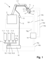
- the invention relates to a system for applying a building material and the use of the system for producing three-dimensional objects from curable building materials, in particular from mineral binders or mineral binder compositions, in particular from concrete and/or mortar compositions.
- generative manufacturing process refers to processes in which a spatial object or a shaped body is produced through targeted spatial deposition, application and/or solidification of material.
- the deposition, application and/or solidification of the material takes place in particular on the basis of a data model of the object to be created and in particular in layers or layers.
- Each object is typically made from one or more layers using generative manufacturing processes.
- a shapeless material e.g. liquids, powders, granules, etc.
- a shape-neutral material e.g. strips, wires
- Generative manufacturing processes are also referred to as “additive manufacturing processes”, “additive manufacturing” or “3D printing”, among other things.
- WO 2013/064826 A1 a method and a device for applying cementitious materials.
- Liquid cementitious material is applied to a destination using a movable robot arm.
- the disadvantage of such systems is that the building material is often not sufficiently constant with regard to various Properties, especially regarding mixing of components. This can lead to irregularities in a structure made with the building material.
- the cured building material composition depending on the objects to be manufactured, different requirements are placed on the cured building material composition. For example, it may be necessary to control the flow properties, kinetics and shrinkage behavior during the solidification and curing process or the strength and surface finish after curing in order to produce an object with the desired properties.
- the object of the present invention is therefore to create improved systems for the generative production of moldings.
- the systems should in particular enable efficient, reliable and as flexible as possible production of moldings from curable building materials, in particular from mineral binder compositions. If possible, this should be done with as little outlay on equipment as possible and as cost-effectively as possible.
- Binder compositions are produced. Due to the limited expenditure on equipment, the costs for the systems according to the invention can be kept relatively low.
- the system can also be expanded in a relatively simple manner for various applications using designed control units and/or optional measuring units.
- building material is understood to mean a material which is formed from or consists of at least two separate components.
- the building material is used in particular to construct three-dimensional objects, which can, for example, be components of structures and/or buildings.
- a “hardenable building material” refers to a building material that is typically flowable or liquefiable and can harden as a solid after mixing, for example by adding mixing water and/or by mixing components.
- these are reactive resins, a mineral Binders, mineral binder compositions or mixtures thereof.
- a “setting building material” is a hardenable building material in a setting or hardening state, in which the setting process has been initiated, for example by adding mixing water and/or a hardener.
- Reactive resins are in particular liquid or liquefiable synthetic resins that harden to duromers through polymerization or polyaddition.
- unsaturated polyester resins vinyl ester resins, acrylic resins, epoxy resins, polyurethane resins and/or silicone resins can be used.
- mineral binder is understood to mean, in particular, a binder which reacts in the presence of water in a hydration reaction to form solid hydrates or hydrate phases.
- This can be, for example, a hydraulic binder (e.g. cement or hydraulic lime), a latent hydraulic binder (e.g. slag), a pozzolanic binder (e.g. fly ash) or a non-hydraulic binder (e.g. gypsum or white lime).
- a “mineral binder composition” is accordingly a composition containing at least one mineral binder. In the present case, this contains in particular the binder, aggregates and optionally one or more additives. Aggregates that can be present include, for example, aggregates, gravel, sand (in natural and/or processed (e.g. broken) form) and/or fillers.
- the mixing device is designed in particular in such a way that it can be operated continuously while the setting building material is being applied.
- the mixing device is preferably designed such that an average residence time of the components of the curable building material in the mixing device, in particular a dynamic mixer, is less than 10 s, more preferably less than 7 s, particularly preferably less than 4 s.
- the average residence time of the components of the curable building material in the mixing device is the average length of time that a particle of the curable building material stays in the mixing device, from the inlet to the outlet.
- the mixing device preferably includes a dynamic mixer.
- a “dynamic mixer” is understood to mean a mixing device which comprises movable elements and is suitable for mixing solid and/or liquid components by moving the movable elements. Using a dynamic mixer, particularly effective mixing of the components can be achieved and energy can be introduced into the curable building material during the mixing process. This is particularly advantageous if the curable building material comprises a mineral binder composition.
- a static mixer can also be used.
- a static mixer is a mixer in which mixing is effected solely by the flow movement of the fluids moved through the mixer, without any moving elements being present.
- a static mixer has flow-influencing elements in a tubular mixing chamber. The flow-influencing elements can deflect, divide and/or merge the material flow, thereby achieving mixing.
- the print head is advantageously arranged spatially separated and/or spaced apart from the mixing device, in particular a dynamic mixer. This applies in particular to all dynamic mixers in the system.
- the mixing device in particular a dynamic mixer, is arranged such that when the print head moves during operation, a position of the print head is changed relative to the mixing device, in particular a dynamic mixer. This applies in particular to all dynamic mixers.
- the mixing device in particular a dynamic mixer of the mixing device, is preferably arranged stationary. This means that it does not have to move with the moving print head during operation. All dynamic mixers are preferably arranged stationary.
- the mixing device in particular a dynamic mixer, is not arranged on the movable print head and/or no mixing device, in particular no dynamic mixer, is arranged on the movable print head.
- the mixing device includes a dynamic mixer and a static mixer, the static mixer preferably being arranged in the delivery line and/or in the print head.
- the dynamic mixer is preferably arranged at a distance from the static mixer in the direction of flow.
- the dynamic mixer is arranged in front of the static mixer in the direction of flow.
- the hardenable building material can be mixed again in the static mixer after initial mixing in the dynamic mixer. If the static mixer is arranged directly in front of the print head or in the print head itself, this can be done immediately before the setting building material exits the print head, which can improve the homogeneity of the setting building material emerging from the print head.
- a static mixer in the area of the print head also has the advantage that it can be integrated into the delivery line or be present as part of it, whereby the area of the print head can be kept compact.
- static mixers are typically relatively light compared to dynamic mixers, which means that the mechanics for moving the print head have to be less robust, which reduces both the equipment complexity and the costs.
- the device for influencing the chemical and/or physical properties of the setting building material there is also a device for influencing the chemical and/or physical properties of the setting building material.
- the device for influencing the chemical and/or physical properties is preferably arranged in or on the delivery line and/or the print head. Especially in or on the print head.
- setting building material can be controlled and/or adjusted, for example with regard to the flow properties and/or the solidification behavior.
- an inlet nozzle for adding an additive to the setting building material.
- the additive serves in particular to influence the chemical and/or physical properties of the setting building material.
- the additive is preferably selected from a retarder, a rheology aid and/or a flow agent. This is preferably a retarder, a rheology aid or a flow agent for mineral binder compositions.
- Retarders are, for example, selected from the list comprising hydroxycarboxylic acids, sucrose and/or phosphates. This is particularly true if the curable building material is a mineral binder or a mineral binder composition.
- rheological aid is understood to mean a substance that can change the rheological properties of the setting building material, in particular a water-containing mineral binder composition, in particular it increases the viscosity, the yield point and/or the thixotropy.
- the rheology aid is selected from the group consisting of modified starches, modified celluloses, microbial polysaccharides and/or mineral thickeners.
- the modified starch is preferably a starch ether, in particular hydroxypropyl starch, carboxymethyl starch or carboxymethylhydroxypropyl starch.
- the modified cellulose is preferably methyl cellulose, Ethylcellulose, hydroxymethylcellulose, hydroxyethylcellulose or methylhydroxyethylcellulose.
- the above-mentioned representatives of additives can be used to adjust the flow, setting or hardening behavior of curable building materials in the form of mineral binder compositions particularly well.
- the rheology aid is particularly suitable for ensuring the dimensional stability of the water-containing binder composition and for giving an applied layer sufficient stability to support one or more further layers without significantly changing the shape.
- the use of retarders can be advantageous because it extends the processing time of the water-containing binder composition.
- the inlet nozzle is located in the flow direction in front of any static mixer and/or in the area of an outlet opening of the print head. This means that the additive can be effectively added to the setting building material and mixed with it if necessary.
- an additive can also be present as part of a component and/or as a separate component when mixing the at least two components.
- a device for ventilation and/or ventilation of the setting building material This is in particular an air supply system, a vacuum treatment device and/or a vibration device.
- the device for ventilation and/or venting is preferably present on or in the delivery line and/or on or in the print head.
- the flow properties of the setting building material can be controlled and/or changed during application using a device for ventilation and/or venting. This can be useful, for example, to keep the flow properties constant under changing environmental conditions and/or to adapt the flow properties to the section of the object to be created.
- a device for changing the temperature of the setting building material This is in particular a heating element and/or a cooling element.
- the device for changing the temperature is preferably present on or in the delivery line and/or on or in the print head.
- the temperature of the setting building material can be controlled and/or changed during application. This can be useful, for example, to monitor and/or control the solidification and/or hardening processes.
- the temperature of the setting building material can be adjusted as environmental conditions change.
- the solidification and/or hardening processes can be changed for different sections of the object to be produced by adjusting the temperature.
- the feed device is advantageously designed in such a way that a solid component of the building material can be added to the mixing device via a first inlet and a liquid component via a second inlet.
- a solid component of a mineral binder composition which comprises, for example, a mineral binder and aggregates in solid form, to be added to the mixing device via the first inlet, while a liquid component, e.g. water, is added separately from the first component via the second inlet can be.
- a liquid component e.g. water
- the feed device is designed such that at least three separate components of the building material can be added to the mixing device via at least three separate inlets.
- a solid component of a mineral binder composition comprising, for example, a mineral binder and aggregates in solid form, may be added to the mixing device via the first inlet.
- a second component which comprises, for example, fibers, can then be added separately into the mixing device via the second inlet, while the third component, for example water, can be added into the mixing device separately from the other two components via the third inlet. This means that the mixing ratio of all three components can be adjusted at any time.
- curable building material can be adapted to almost any desired composition in terms of its composition.
- the feed device advantageously has a further inlet, which corresponds, for example, to an additive reservoir, and a further outlet, which is connected to the inlet nozzle.
- fibers are understood to mean materials whose ratio of length to diameter or length to equivalent diameter is at least 10:1. This ratio is also known as the form factor.
- equivalent diameter of a fiber is understood to mean the diameter of a circle having the same area as the cross-sectional area of a fiber with a non-round cross-section.
- the feeding device has in particular at least one or more metering devices.
- the at least one metering device is designed such that one or more of the components of the curable building material can be metered into the mixing device in a controlled manner and/or at a defined addition rate.
- each inlet of the mixing device prefferably has a separate and individually controllable metering device.
- the feed device advantageously has a further metering device, which is designed such that an additive can be added to the inlet nozzle in a controlled manner and/or at a defined addition rate.
- the metering device is a gravimetric metering device.
- such metering devices have proven to be easy to handle, but still precise.
- Providing a gravimetric metering device offers the advantage that a component, in particular a solid component, can be supplied to the system in precise quantities. This allows the quality of the building material to be kept constant.
- the metering device comprises a funnel and a conveyor device.
- the conveyor device can in particular be designed as a screw conveyor or conveyor belt.
- Providing a funnel and a conveyor device has the advantage that large units of a component of the building material, such as large containers or sacks (called “big bags” in technical language), can be used. For example, such large units can be hung in a container and fed to a conveyor device via a funnel.
- the funnel has the advantage that it can be used as a storage device, thus saving a period of time when the containers in the first one are replaced Part of the first component of the building material can bridge. For example, a first component can be fed to the metering device by the conveying device.
- the conveying device is present in the mixing device, in the conveying line and/or in the print head, or the conveying device is a component of these elements. This makes a compact design possible. However, arrangements of the conveyor device are also possible.
- a pump is used as the conveying device, for example a screw conveyor.
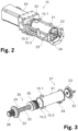
- the mixing device comprises a stirring shaft, which is equipped with stirring elements on a first section and on which a conveying element is arranged on a second section.
- the components of the curable building material can be mixed in this way in the mixing device and at the same time conveyed out of the mixing device in mixed form.
- the stirring elements are designed as pins.
- the stirring elements have an external thread, so that the stirring elements can be screwed into recesses with internal threads on the stirring shaft.
- the conveying element is designed as a screw conveyor.
- the first section of the agitator shaft is arranged in a first region of a drum of the mixer, in which the drum has at least two has inlets.
- the second section of the agitator shaft is arranged in a second area of the drum, in which the drum has an outlet.
- the conveying element can be removed from the agitator shaft in the direction of an axis of the agitator shaft.
- the conveying element comprises a fastening element for locking the conveying element on the agitator shaft.
- a drum of the mixer is designed in one piece and/or tubular.
- the system according to the invention has at least one container in which at least one of the two components of the building material can be stored.
- the system according to the invention particularly preferably has at least two containers in which the at least two components of the building material can be stored spatially separated.
- system according to the invention can have a reservoir for an additive.
- An additive which is added via the inlet nozzle, for example, can be stored in such a reservoir.
- the one or more containers preferably correspond to the feed device, so that a component present in a container can be fed directly into the mixing device via an assigned inlet.
- the system according to the invention can produce a defined part or the entire object to be produced essentially without further intervention after loading the containers and/or connecting to a transport line.
- a measuring unit with which a chemical and/or physical property of the curable building material can be determined in the mixing device, in the delivery line, in the print head and/or after delivery from the print head.
- a chemical and/or physical property of the setting building material By determining a chemical and/or physical property of the setting building material, its specific condition can be assessed. This makes it possible, if necessary, to adjust, for example, the ratio of the components, the conveying speed of the setting building material and/or the addition rate of an additive depending on the chemical and/or physical properties. Overall, a more constant quality of the curable building material can be achieved and/or the curable building material can be specifically adapted or changed for specific sections of the object to be produced.
- the measuring unit is in particular designed such that a measuring frequency for determining the chemical and/or physical property is >0.01 Hz, preferably >0.1 Hz, particularly preferably >1 Hz, very particularly preferably >10 Hz. This allows the chemical and/or physical properties of the setting building material to be determined at regular intervals or continuously.
- the measuring unit is particularly preferably designed in such a way that the chemical and/or physical property can be determined during the application of the building material, in particular in real time.
- the measuring unit is preferably arranged in the mixing device, in the delivery line and/or in the print head.
- the measuring device comprises a temperature measuring device, a pressure measuring device, a moisture measuring device, a measuring device for determining electrical conductivity, a penetrometer, an ultrasonic transducer and/or a rheometer.
- a temperature measuring device e.g., a thermometer, a pressure measuring device, a moisture measuring device, a measuring device for determining electrical conductivity, a penetrometer, an ultrasonic transducer and/or a rheometer.
- an outlet on the print head that can be controlled with respect to the size of the passage opening, the outlet preferably being completely closable.
- This can be done, for example, by means of a valve that can be opened and closed, the valve being able to be opened and closed in particular pneumatically and/or electromechanically. This allows the delivery rate to be specifically adjusted when applying the setting building material.
- the system according to the invention has a control unit.
- the control unit is designed in particular in such a way that at least some of the devices and units present in the system can be controlled and/or regulated in a controlled manner.
- the term “regulate” or “regulated” is understood in particular to mean the setting of a predetermined target value and its maintenance for a defined period of time.
- the control unit has in particular a processor, a data memory, an interface for receiving data from any existing measuring devices and/or an interface for controlling devices of the system according to the invention.
- the devices and units present in the system are preferably connected to the control unit via data lines, control lines and/or wireless communication systems.
- controllable devices are in particular the movable print head, the controllable outlet opening, the mixing device, the conveying device, the inlet nozzle and/or the feed device.
- a data model which represents at least part of the object to be created or the entire object to be created is preferably stored in the control unit.
- the control unit is also advantageously designed in such a way that parameters and/or target values to be maintained during the application can be determined taking the data model into account.
- parameters and/or target values are preferably defined for different sections of the object to be created and/or these are present in the control unit.
- the parameters or target values are, for example, the delivery rate of the conveying device, the size of the opening of the outlet nozzle, the mixing ratio of the at least two components, the addition rate of the additive via the inlet nozzle, the pressure of the setting building material, the viscosity of the setting building material, etc Temperature of the setting building material and/or the ambient temperature of the area in which the object to be created is created.
- one or more properties of the at least two components of the curable building material for example the chemical composition, a previously determined flow limit and/or a previously determined viscosity, can or are stored in the control unit.
- the control unit is preferably designed such that the size of the passage opening of the controllable outlet is controlled depending on the structure of the object to be produced. This allows the structure to be created to be produced more precisely and in a more controlled manner.
- control unit is designed in such a way that the conveying capacity of the conveying device is determined in relation to a chemical and/or physical property of the curable building material determined by the measuring unit, in particular in relation to a pressure of the curable building material in the conveying line and/or in the print head. is controlled and/or regulated.
- control unit is designed such that the conveying capacity of the conveying device is regulated in relation to a fill level of the components in one or more containers. This can prevent the system from running empty and air being introduced.
- control is designed in such a way that an addition rate of at least one component of the building material with the feed device depends on the chemical and/or physical properties of the curable building material and/or depending on the size and/or structure of the material to be created Object, can be regulated or takes place.
- the composition and properties of the curable building material can be kept constant and/or adjusted in a targeted manner.
- the control is advantageously designed in such a way that the addition rate can or does take place during the application of the curable building material, in particular in real time.
- control unit which is designed such that a volume flow of the curable building material emerging from the print head depends on the size and/or the structure of an object to be created with the curable building material.
- the control unit is preferably designed in such a way that the conveying device takes place depending on a chemical and/or physical property of the curable building material and/or depending on the size and/or structure of an object to be produced with the curable building material.
- control unit is designed in particular in such a way that an addition rate of an additive, in particular a rheology aid and/or a retarder, via the inlet nozzle depends on a chemical and/or physical property of the curable building material and/or depending on the size and/or the Structure of an object to be created with the curable building material is controlled.
- control unit is designed in such a way that the application of the setting building material is controlled and/or regulated taking into account the ambient temperature of an area in which the object to be created is created.
- the addition rate of an additive via the inlet nozzle, the delivery rate of the conveying device and/or the addition rate of at least one component of the building material can be controlled and/or regulated depending on the ambient temperature of an area in which the object to be created is produced.
- control unit is designed such that the delivery rate and the movement of the print head are coordinated with one another.
- the first component is a dry mineral binder composition comprising cement and mineral fillers, the binder composition containing at least one setting accelerator based on aluminum sulfate, at least one superplasticizer based on a polycarboxylate ether and comprises at least one rheology aid, wherein the polycarboxylate ether, assuming all carboxylic acid groups are present as a free acid, has at least 1 mmol, in particular at least 1.2 mmol, in particular at least 1.8 mmol, of carboxylic acid groups per gram of dry polycarboxylate ether.
- dry mineral binder composition is understood to mean a free-flowing mineral binder composition with a moisture content of less than 0.5% by weight.
- water-containing mineral binder composition is understood to mean a mineral binder composition mixed with water, in particular in fluid form. Accordingly, a “water-containing mineral binder composition” is a curable building material in a setting state.
- polycarboxylate ether is understood to mean a comb polymer comprising a backbone made of hydrocarbons with carboxylic acid groups or their salts bound thereto and polyalkylene glycol side chains also covalently bound to the backbone.
- the side chains are bonded to the polycarboxylate backbone in particular via ester, ether, imide and/or amide groups.
- the amount of carboxylic acid groups in the polycarboxylate ether is understood to be millimoles of carboxylic acid groups in one gram of the polycarboxylate ether (mmol/g).
- any salts of the carboxylic acids that may be present are counted among the carboxylic acid groups and the weight of the polycarboxylate ether is used in non-neutralized form.
- Carboxylic acid esters are not counted among the carboxylic acid groups here, even if they are present in latent form, that is, if they can be hydrolyzed in an alkaline medium at pH 12.
- dimensional stability is understood to mean a material property in which the material changes the individual dimensions by a maximum of 10% after shaping, provided that no external force other than gravity acts on the shaped material.
- “stability” is understood to mean the strength that a curable material has after application before curing.
- cement type or a mixture of two or more cement types can be used as cement, for example those classified under DIN EN 197-1 Cements: Portland cement (CEM I), Portland composite cement (CEM II), blast furnace slag cement (CEM III), Pozzolanic cement (CEM IV) and composite cement (CEM V).
- CEM I Portland cement
- CEM II Portland composite cement
- CEM III blast furnace slag cement
- CEM IV Pozzolanic cement
- CEM V composite cement
- cements produced according to an alternative standard such as the ASTM standard or the Indian standard, are equally suitable.
- Portland cement CEM I or CEM II according to DIN EN 197-1 is preferred.
- Portland cement CEM 142.5 or CEM I 52.5 is particularly preferred. Such cements provide good strength and good workability.
- the dry mineral binder composition advantageously also contains at least one latent hydraulic or pozzolanic binder, in particular metakaolin and/or silica fume (amorphous SiO 2 ).
- the latent hydraulic or pozzolanic binder is preferably present in the binder composition in 0.1 to 10% by weight, in particular in 0.5 to 5% by weight. These additives can increase the processability of the aqueous binder composition and the strength of the cured binder composition.
- the dry mineral binder composition contains mineral fillers.
- Fillers are chemically inert solid particulate materials and are offered in various shapes, sizes and materials, ranging from the finest sand particles to large coarse stones. In principle, all fillers that are commonly used for concrete and mortar are suitable. Examples of particularly suitable fillers are aggregates, gravel, sand, especially quartz sand, limestone sand and slag sand, crushed stones, calcined pebbles or light fillers such as expanded clay, expanded glass, foam glass, pumice, perlite and vermiculite. Further advantageous fillers are fine or very fine fillers such as ground limestone or dolomite, aluminum oxide, silica fume, quartz powder or ground steel slag with no or only weak latent hydraulic reactivity.
- Preferred fillers are selected from the group consisting of quartz sand, quartz powder, limestone sand, ground limestone and ground steel slag.
- the filler preferably comprises at least one finely ground crystalline filler, in particular limestone. This can promote the early strength development of the binder composition mixed with water.
- the particle size of the fillers depends on the application and ranges from 0.1 ⁇ m to 32 mm and more. Different particle sizes are preferably mixed in order to optimally adjust the properties of the binder composition. Fillers made from different materials can also be mixed. The particle size can be determined using a sieve analysis.
- the particle size is determined in particular by the planned layer thickness of the applied layers in 3D printing or the generative manufacturing process. A maximum particle size of the fillers is therefore sensibly as large as the layer thickness during application.
- the dry mineral binder composition preferably contains 20 to 40% by weight, in particular 22 to 36% by weight, based on the total weight of the dry binder composition, of fine fillers with a particle size of less than 0.125 mm.
- Suitable fillers with a small particle size are, in particular, fine quartz sand, quartz powder, ground calcium carbonate or ground steel slag.
- the mineral binder composition preferably contains 1 to 10% by weight, more preferably 2 to 5% by weight, of ground calcium carbonate with a particle size of less than 0.01 mm.
- the fine calcium carbonate improves the processability of the water-mixed binder composition and can increase the strength development of the binder composition.
- Aqueous binder compositions with such particle sizes are easy to convey, can be mixed well with the aqueous accelerator in the continuous mixer and result in a very homogeneous surface after application.
- fillers with particle sizes of up to 32 mm, more preferably up to 20 mm, most preferably up to 16 mm, can also be used.
- the mineral fillers are preferably present in 45 to 85% by weight, in particular 50 to 80% by weight, based on the total weight of the dry mineral binder composition.
- the dry mineral binder composition preferably contains an aluminum sulfate-based accelerator.
- the accelerator is a free-flowing powder and advantageously contains at least 30% by weight, preferably at least 35% by weight, more preferably at least 40% by weight, aluminum sulfate, calculated as aluminum sulfate hydrate Al 2 (SO 4 ) 3 ⁇ 16 H 2 O.
- the accelerator can advantageously contain other components such as amino alcohols, alkali and alkaline earth metal nitrates, alkali and alkaline earth metal nitrites, alkali and alkaline earth metal thiocyanates, alkali and alkaline earth metal halides, alkali carbonates, glycerol, glycerol derivatives, other aluminum salts, aluminum hydroxides, alkali and alkaline earth metal hydroxides, alkali - and alkaline earth metal silicates, alkali and alkaline earth metal oxides or alkali and alkaline earth metal salts of formic acid, or mixtures thereof.
- other components such as amino alcohols, alkali and alkaline earth metal nitrates, alkali and alkaline earth metal nitrites, alkali and alkaline earth metal thiocyanates, alkali and alkaline earth metal halides, alkali carbonates, glycerol, glycerol derivatives, other aluminum salt
- the accelerator consists of at least 90% by weight, in particular at least 95% by weight, of aluminum sulfate hydrate or is aluminum sulfate hydrate.
- the binder composition is preferably free of amino alcohols.
- Amino alcohols have an intense, unpleasant smell, can endanger health and lead to uncontrolled stiffening of the binder composition mixed with water.
- the accelerator based on aluminum sulfate is preferably present in 0.1 to 2% by weight, more preferably in 0.3 to 1.5% by weight, in particular in 0.4 to 1.0% by weight, based on the total weight of the dry mortar mixture.
- Such a dosage of the accelerator leads to a rapid development of strength of the binder composition mixed with water without restricting the processability for the printing process, especially in combination with polycarboxylate ethers.
- the binder composition comprises at least one superplasticizer based on a polycarboxylate ether.
- the at least one polycarboxylate ether contains carboxylic acid groups in the form of free, that is to say non-neutralized, carboxylic acid groups and/or in the form of their alkali metal and/or alkaline earth metal salts. Polycarboxylate ethers which have no further anionic groups in addition to the carboxylic acid groups are preferred.
- polycarboxylate ethers whose side chains consist of at least 80 mol%, preferably at least 90 mol%, particularly preferably 100 mol%, of ethylene glycol units.
- the side chains preferably have an average molecular weight Mw in the range from 500 to 10,000 g/mol, preferably 800 to 8,000 g/mol, particularly preferably 1,000 to 5,000 g/mol. It Side chains with different molecular weights may also be present in the polycarboxylate ether.
- polycarboxylate ethers which are made up of methacrylic acid and/or acrylic acid units and methyl polyalkylene glycol methacrylates or acrylates.
- the at least one polycarboxylate ether preferably has an average molecular weight Mw of 8,000 to 200,000 g/mol, in particular 10,000 to 100,000 g/mol, measured against polyethylene glycol standards.
- Such polycarboxylate ethers are particularly suitable for enabling good processability of the binder composition even at low water contents.
- a low water content results in high strength of a hardened molded body.
- such polycarboxylate ethers work particularly well as an agent for controlling the stiffening of the aqueous binder composition.
- the at least one polycarboxylate ether can be introduced into the binder composition as an aqueous solution, for example by spraying onto the fillers before mixing with the mineral binder.
- the at least one polycarboxylate ether is preferably present as a polymer powder in the dry binder composition.
- the at least one polycarboxylate ether has a block or gradient structure.
- “polycarboxylate ether with block or gradient structure” is understood to mean a polymer in which the monomer units are present in a non-random sequence, i.e. the sequence is not obtained randomly.
- at least one section comprises monomer units comprising polyalkylene glycol side chains and no or hardly any monomer units with carboxylate groups and at least one section comprises monomer units with carboxylate groups and no or hardly any monomer units with polyalkylene glycol side chains.
- Such block or gradient polymers therefore have sections with a high density of anionic groups and sections that contain no or only a few anionic groups.
- polycarboxylate ethers with a block or gradient structure very quickly develop their effect as plasticizers. They are therefore particularly suitable for applications in which the mixing time of binder composition and water is very short, especially for continuous mixing.
- Polycarboxylate ethers with a block or gradient structure also result in a low viscosity of the binder composition, which improves pumpability.
- the liquefying effect of the polycarboxylate ethers with block or gradient structure in the binder compositions according to the invention only lasts for a few minutes, which is advantageous for 3D printing because it ensures good processability of the aqueous binder composition directly after mixing and good stability after application can be achieved.
- the at least one polycarboxylate ether is preferably present at 0.02 to 5% by weight, preferably at 0.05 to 4% by weight, in particular at 0.1 to 3% by weight, calculated as a dry polymer, based on the total weight of the dry binder composition.
- the dosage of the at least one polycarboxylate ether in the binder composition is advantageously adapted to the respective printing task.
- the printing parameters such as typically the desired height of the molded body, the thickness of the applied layers, the printing speed and the expected ambient temperature, are advantageously recorded before printing and then the optimal amount of polycarboxylate ether in the binder composition is determined using empirical values, tables and/or a computer program determined.
- the total amount of polycarboxylate ether is provided in the dry binder composition.
- the further part of the polycarboxylate ether is advantageously added together with the mixing water in a continuous mixing process.
- the binder composition can thus be produced in large quantities, which is advantageous, and the adaptation to the respective pressure conditions is carried out easily and inexpensively on the construction site.
- the binder composition preferably contains at least one organic and/or inorganic rheology aid.
- Suitable rheology aids are, in particular, modified starch, amylopectin, modified cellulose, microbial polysaccharides, galactomannans, alginates, tragacanth, polydextrose, superabsorbents or mineral thickeners.
- the rheology aid is preferably selected from the group consisting of modified starches, modified celluloses, microbial polysaccharides, superabsorbers and mineral thickeners.
- the total amount of rheology aid is preferably 0.01 to 5% by weight, based on the total weight of the dry binder composition.
- the modified starch is preferably a starch ether, in particular hydroxypropyl starch, carboxymethyl starch or carboxymethylhydroxypropyl starch.
- the modified starch is preferably present in 0.01 to 2% by weight, based on the total weight of the dry binder composition.
- the modified cellulose is preferably methylcellulose, ethylcellulose, hydroxymethylcellulose, hydroxyethylcellulose or methylhydroxyethylcellulose and is preferably present in 0.01 to 2% by weight, based on the total weight of the dry binder composition.
- the microbial polysaccharide is preferably Welan Gum, Xanthan Gum or Diutan Gum and is preferably present in 0.01 to 0.1% by weight, based on the total weight of the dry binder composition.
- the superabsorber is preferably selected from the group comprising polyacrylamide, polyacrylonitrile, polyvinyl alcohol, isobutylene-maleic anhydride copolymers, polyvinylpyrrolidone, homo- and copolymers of monoethylenically unsaturated carboxylic acids such as (meth) acrylic acid, crotonic acid, sorbic acid, maleic acid, fumaric acid, itaconic acid, preferably polyacrylic acid, which can be partially or completely neutralized, and co- and terpolymers of the above-mentioned monoethylenically unsaturated carboxylic acids with vinyl sulfonic acid, (meth) acrylamidoalkyl sulfonic acids, allyl sulfonic acid, vinyl toluene sulfonic acid, Vinylphosphonic acid, (meth)acrylamide, N-alkylated (meth)acrylamide, N-methylol (meth)acrylamide, N-vinylform
- the superabsorbent homo- and copolymers can be linear or branched; the copolymers can be present randomly or as block or gradient polymers.
- the homo- and copolymers are preferably also cross-linked.
- the superabsorber is preferably polyacrylic acid, which can be partially or completely neutralized and crosslinked.
- the superabsorbent if present, is preferably present in 0.01 to 0.5% by weight, in particular in 0.05 to 0.3% by weight, based on the total weight of the dry binder composition.
- mineral thickeners For example, special silicates or clay minerals can be used as mineral thickeners. Bentonite and sepiolite are preferred.
- the mineral thickener is preferably present in 0.1 to 1% by weight, based on the total weight of the dry binder composition.
- the binder composition preferably contains at least two, more preferably at least three, different rheology aids.
- the rheology aid is particularly suitable for ensuring the dimensional stability of the water-containing binder composition and for giving an applied layer sufficient stability to support one or more further layers without significantly changing the shape before the cement begins to hydrate.
- the different thickening properties of the rheology aids can be optimally coordinated with one another. This results in good processability and good stability of the water-containing binder composition.
- a combination of rheology aids which comprises at least one superabsorber is particularly preferred.
- the superabsorbent also acts as a means of reducing shrinkage, which is particularly advantageous.
- the binder composition preferably also contains 0.1 to 5% by weight, preferably 0.5 to 3% by weight, of calcium sulfoaluminate, based on the total weight of the dry binder composition.
- the calcium sulfoaluminate especially in the preferred dosage, can on the one hand increase the early strength development of the aqueous binder composition and at the same time reduce shrinkage.
- a higher level of calcium sulfoaluminate in the binder composition can reduce the final strength of a printed article and increases the cost of the composition.
- the special combination of calcium sulfoaluminate and rheology aids can greatly reduce the shrinkage of the binder composition after application. Shrinkage can lead to the formation of cracks in the molded article produced. Cracks can reduce the durability of the printed structures and disrupt the visual impression.
- Calcium sulfoaluminate is particularly advantageous as a calcium sulfoaluminate cement.
- the binder composition advantageously contains at least one further additive for reducing shrinkage selected from the group consisting of glycols, polyglycols and water-storing materials, such as in particular porous stones, ground bricks, and/or ground cement stone.
- the binder composition preferably also contains at least one defoamer, in particular selected from the group consisting of oil-based defoamers, in particular defoamers based on mineral oil, vegetable oil or white oil which contain a wax and/or hydrophobic silica, silicone-based defoamers which can be modified, for example, by alkoxylation or fluorination, alkyl esters of phosphoric or phosphonic acid, alkoxylated polyols, in particular ethoxylated diols, fatty acid-based defoamers, in particular mono- and diglycerides of fatty acids and alkoxylated fatty alcohols, and mixtures thereof.
- defoamer in particular selected from the group consisting of oil-based defoamers, in particular defoamers based on mineral oil, vegetable oil or white oil which contain a wax and/or hydrophobic silica, silicone-based defoamers which can be modified, for example, by alkoxylation or flu
- the defoamer is preferably selected from the group comprising ethoxylated 2,4,7,9-tetramethyl-5-decyn-4,7-diol, a combination of fatty alcohol alkoxylates and polysiloxane and a combination of mineral oil and a silicone oil containing hydrophobic silica.
- the defoamer is preferably present in 0.01 to 1% by weight, in particular in 0.1 to 0.8% by weight, based on the total weight of the dry binder composition.
- a defoamer is advantageous because it prevents or reduces the formation of air voids when the dry binder composition is mixed with water. Air pores can disrupt the delivery of the water-containing binder composition to the print head, and reduce the strength of the cured molded body, and pores disrupt the visual impression of the molded body.
- the defoamer also reduces shrinkage and thus the formation of cracks in the hardened molded body.
- the mineral binder composition can contain at least one further additive, for example a concrete additive and/or a mortar additive.
- the at least one further additive includes in particular a flow agent, a retarder, a defoamer, a wetting agent, fibers, a dye, a preservative, a further accelerator, a dispersion polymer, a cationic polymer, a cationic polycondensate, a cationic comb polymer, an air entraining agent, a another shrinkage reducer or a corrosion inhibitor or combinations thereof.
- the flow agent is in particular sodium gluconate, a lignosulfonate, a sulfonated naphthalene-formaldehyde condensate, a sulfonated melamine-formaldehyde condensate, a sulfonated vinyl copolymer, a polyalkylene glycol with phosphonate groups, a polyalkylene glycol with phosphate groups or an aromatic condensate with phosphonate groups and polyalkylene glycol chains.
- the use of hardening retarders can be advantageous because it extends the processing time of the water-containing binder composition.
- the hardening retarder is preferably a hydroxycarboxylic acid, in particular tartaric acid, Citric acid or gluconic acid, a sugar, especially sucrose, a phosphate or a phosphonate, or their salts or mixtures thereof.
- the accelerator and the polycarboxylate ether are preferably metered in such an amount that a binder composition mixed with water remains easily moldable for several seconds to a few minutes.
- the layers can be applied homogeneously, form a good cohesion and the surface of the shaped body produced can, if desired, be further treated, for example smoothed.
- a water-containing mineral binder composition that is optimal for the process is obtained in a setting state.
- Mixing with water is preferably carried out using a continuous mixer.
- the strength development of the water-containing binder composition is advantageously determined before its application. This helps to be able to set the printing parameters and/or to adjust the binder composition, in particular the content of polycarboxylate ether in the dry and/or water-containing binder composition.
- the start of setting of the water-containing binder composition is between about 10 minutes and 1 hour, and the end of setting is between about 30 minutes and 3 hours, measured according to DIN EN 196-3 at 20 ° C with an automatic Vicat apparatus.
- the binder composition reaches a strength of at least 0.05 MPa, preferably at least 0.08 MPa, in particular at least 0.1 MPa, one hour after application, and at least 0.5 MPa, in particular 1 MPa, after 3 hours, preferably 2 hours.
- Strength can be determined using a penetration method such as that described in ASTM C 403.
- Such strength development of the water-containing binder composition is particularly advantageous for the efficient and homogeneous production of moldings.
- a further aspect of the present invention relates to the use of a system as described above for producing three-dimensional objects from curable building materials.
- the curable building materials are preferably mineral binders or mineral binder compositions, in particular concrete and/or mortar compositions.
- the objects produced can have almost any shape.
- An object can, for example, be a building, a prefabricated part for a building, a structural element, a masonry, a bridge, a column, a decorative element such as artificial mountains, reefs or sculptures, a pool, a fountain or a tub.
- the shaped body can be a solid shape or a hollow shape, with or without a bottom.
- FIG. 1 an exemplary system 1 for applying a curable building material is shown schematically.
- the system 1 includes a movement device 2 with a movable arm 2.1.
- a print head 3 is attached to the free end of the arm 2.1 and can be moved in all three spatial dimensions by the arm 2.1. The print head 3 can thus be moved to any position in the working area of the movement device 2.
- the print head 3 has an inside facing the arm 2.1 end face (in Fig. 1 above) to the opposite and free end face continuous tubular passage 3.1 for the passage of hardenable building material. At the free end, the passage 3.1 opens into a controllable outlet 4 in the form of a nozzle that can be continuously opened and closed.
- An inlet nozzle 5 for adding an additive opens laterally into the passage 3.1 in an area facing the arm 2.1. If necessary, an additive, for example a rheology aid, can be added to the curable building material moving through the passage 3.1 through the inlet nozzle 5.
- an additive for example a rheology aid
- a static mixer 6 is further arranged in the passage 3.1, which additionally mixes the curable building material and the additive as it flows through.
- a sampling rate of the measuring unit 8 is, for example, 10 Hz.
- a device 7 for venting the curable building material is also attached to the print head 3.
- the device is designed as a vacuum treatment device and makes it possible to reduce the proportion of air in the curable building material.
- a section of the wall of the passage 3.1 can be designed as a gas-permeable membrane, so that air is drawn out of the curable building material by applying a negative pressure outside the passage 3.1.
- the system 1 for applying a curable building material also has a feed device 9, which corresponds on the input side to three containers 11.1, 11.2, 11.3 and an additive reservoir 11.4.
- Each of the three containers 11.1, 11.2, 11.3 contains one component of the curable building material.
- the first component, which is present in the first container 11.1, comprises, for example, cement and aggregates, for example sand and filler.
- the second component, which is present in the second container 11.2, consists, for example, of water.
- the third component present in the third container 11.3 is, for example, a flow agent in the form of a polycarboxylate ether.
- a rheology aid in the form of modified cellulose and/or a microbial polysaccharide is present in the additive reservoir 11.4.
- the feed device 9 On the output side, the feed device 9 has three separate outlets, each of which is connected to one of three inlets 10.1, 10.2, 10.3 of a mixing device 10.
- the feed device 9 also has individually controllable dosing devices (in Fig. 1 not shown), so that the individual components in the individual containers 11.1, 11.2, 11.3 can be dosed individually into the mixing device 10.
- Another outlet of the feed device is connected to the inlet nozzle 5 (in Fig. 1 not shown), so that additives can be conveyed from the additive reservoir 11.4 into the inlet nozzle 5 via a further metering device of the feed device 9.
- the mixing device 10 is designed as a dynamic mixer and, in addition to this, includes an integrated conveying device in the form of a screw conveyor.
- the mixing device the individually metered components are mixed with one another and conveyed into the flexible line 12 attached to the output side of the mixing device.
- the curable building material can be mixed and conveyed continuously.
- the curable building material can be conveyed into the print head 3 and continuously applied through the controllable outlet 4.
- a measuring unit 13 which is integrated into the delivery line 12 in the area between the mixing device 10 and the print head 3.
- the measuring unit contains, for example, an ultrasound transducer, which is designed to determine the flow properties of the curable material.
- a sampling rate of the measuring unit 13 is, for example, 10 Hz.
- a central control unit 14 of the system 1 includes a processor, a memory unit and several interfaces for receiving data and several interfaces for controlling individual components of the system 1.
- the mixing device 10 is connected to the control unit 14 via a first control line 15a, while the feed device is connected to the control unit 14 via a second control line 15b. This allows the individual components in the containers 11.1, 11.2, 11.3 to be metered into the mixing device 10 via the central control unit in accordance with predetermined recipes stored in the control unit and conveyed into the flexible line 12 at adjustable delivery rates.
- controllable outlet 4, the inlet nozzle 5, and the device 7 for venting the curable building material on the print head are each also connected to the control unit 14 via a separate control line 15c, 15d, 15e and can be controlled or monitored by this.
- the movement device 2 is also connected to the control unit 14 via a further control line 15g.
- the movement of the print head 3 can thus be controlled via the control unit 14.
- the measuring unit 8 is connected to the control unit 14 via a data line 15h, so that pressure data recorded in the measuring unit can be transmitted to the control unit 14.
- the measuring unit 13 is connected to the control unit 14 via a data line 15f, so that data recorded in the measuring unit, which characterize the flow properties, can be transmitted to the control unit 14.
- the dry mineral binder composition used as the first component has, for example, the composition described in Table 1.
- Table 1 Composition of the dry binder composition component Weight % in the binder composition Cement CEM I 52.5 25 Metakaolin 4.5 Betoflow ® D 5 Nekafill® 15 20 Sand 0-1mm 42 Denka CSA #20 2 Sika ® ViscoCrete ® -225P 0.25 Carbowet® 4000 0.5 Modified cellulose 0.05 Inorganic thickener 0.10 Superabsorbent 0.1 Aluminum sulfate 0.5
- FIG. 2 is an exemplary embodiment of the mixing device 10 Fig. 1 shown.
- the mixing device 10 comprises a drive 20, a drum 21, a proximal closure 22, a distal closure 23, an outlet 24, a first inlet 10.1, a second inlet 10.2, a third inlet 10.3 and a support device 25.
- the distal closure 23 is connected to the drive 20 via the support device 25, so that a stirring shaft (not visible in this figure) can be stored both in the proximal closure 22 and in the distal closure 23.
- the first component is supplied via the first inlet 10.1, the second component via the second inlet 10.2 and the third component via the third inlet 10.3
- the mixing device 10 is shown without the drive module 20 in a separated state.
- the mixing device 10 comprises a shaft module 26 and a drum module 27.
- the shaft module 26 includes a coupling element 28 for mechanical coupling to the drive unit 20, the proximal closure 22, a stirring shaft 29 and a conveying element 30.
- the drum module 27 comprises an integrally formed tubular drum 31 and a distal closure 23.
- the drum 31 has a first inlet 10.1, a second inlet 10.2 and a third inlet 10.3, all of which are arranged in a first end region of the drum 31 are.
- the outlet 24 is arranged at a second end region of the drum 31.
- the distal closure 23 has a sacrificial plate 32 which is arranged on a side of the distal closure 23 which faces the drum 31.
- the sacrificial plate 32 becomes worn during operation of the system and can be replaced if necessary. This allows the distal closure 23 to be used over a longer period of time.
- the conveying element 30 is designed as a screw conveyor in this exemplary embodiment.
- the conveying element 30 is arranged so that it can be plugged onto the agitator shaft 29.
- the conveying element 30 is secured with a locking element on the agitator shaft 29 (not visible in this illustration).
- pins 33 which protrude radially from the stirring shaft 29 are also fastened as stirring elements (in Fig. 3 only a single pin is shown).
- Fig. 4 illustrates a method using the system 1 according to the invention.
- the dry mineral binder composition from Table 1 (see above) is provided as the first component in the container 11.1.
- Water is placed in container 11.2 as the second component and in container 11.3 a superplasticizer is placed as the third component.
- the components are continuously added to the mixing device 10 via the feed device 9 and mixed there in the next step 43 to obtain a mineral binder composition mixed with water.
- the dry binder composition with the composition given in Table 1 is mixed with such an amount of water in the mixing device 10 that a weight ratio of water to dry binder composition of approximately 0.16 is obtained.
- the superplasticizer is added in such a way that a specified flow limit is reached.
- the mineral binder composition mixed with water corresponds to a hardenable building material in a setting state.
- the prepared binder composition is then fed to the print head 3 via the delivery line 12 in the fourth step 44 using the screw conveyor integrated in the mixing device 10.
- an additive in the form of a rheology aid for example a modified cellulose and/or a microbial polysaccharide, is metered into the prepared binder composition in step 45 via the inlet nozzle 5 and/or the binder composition is vented using the device 7. This means that the chemical and/or physical properties are adjusted if necessary so that specified target values for the flow properties are maintained.
- the binder composition is then applied layer by layer in step 46 via the outlet 4 of the print head, so that the object to be produced is produced.
- All steps in the method 40 including the control of the print head are controlled and monitored with the control unit 14.
- a pipe 2 m high with a diameter of around 600 mm was produced as an example.
- the individual applied layers were approximately 30 mm wide and approximately 10 mm high.
- the horizontal speed of the print head was approximately 40 mm per second.
- the printing of the molded body took 2 hours and 40 minutes.
- the height of the lower layers and the upper layers did not differ by more than 5%.
- the printed molded body had a wavy, very uniform surface with no visible defects. Even after 3 days of storage at 25 ° C and about 40% relative humidity, the molded body showed no visible cracks. About 16 hours after the last layer was applied, the hollow body was lifted onto a transport pallet using carrying straps and a crane without causing any damage to the printed molded body.
- the molded body was destroyed using a heavy hammer and the fragments were analyzed optically.
- the fracture surfaces had a uniform surface, without air pockets or defects.
- the fracture surfaces did not show a preferred orientation, which means that the applied layers had an equally good bond with each other as within the same layer.
- the static mixer 6 can be omitted so that there is neither a static nor a dynamic mixer in the print head.
- one or more further conveying devices can be provided in the conveying line 12 and/or in the print head 3. These can also involve conveying devices other than screw conveyors.
- measuring units in the area of the print head 3 and/or in the delivery line 12 instead of or in addition to the measuring units 8, 13, which, for example, enable temperature measurement. It is also conceivable to completely omit the measuring unit 13 in the delivery line or to integrate it into the print head.
- the mixing device 10 can also have fewer or more inlets so that additional components, which are present in additional containers, can be metered in.
- connections to external sources e.g. to a water connection, can also be present.
- control unit it is also possible to program the control unit differently, for example so that a volume flow through the delivery line 12 and/or the print head 3 is taken into account.
Abstract
Ein System (1) zum Applizieren eines Baustoffs, umfasst:eine Mischvorrichtung (10) zum Vermischen von einzelnen Komponenten des Baustoffs zu einem aushärtbaren Baustoff;einen in wenigstens einer Raumrichtung bewegbaren Druckkopf (3), mit welchem der verarbeitbare Baustoff appliziert werden kann;eine Förderleitung (12), mit welcher der aushärtbare Baustoff von der Mischvorrichtung (10) zum Druckkopf (3) geleitet werden kann;wenigstens eine Fördervorrichtung (30) zum Fördern des aushärtbaren Baustoffs von der Mischvorrichtung (19) durch die Förderleitung (12) zum Druckkopf (3);eine Zuführvorrichtung (9), welche derart ausgebildet ist, dass wenigstens zwei separate Komponenten des Baustoffs über wenigstens zwei getrennte Einlässe (10.1, 10.2, 10.3) in die Mischvorrichtung (10), insbesondere in eine Mischkammer der Mischvorrichtung (10), zugegeben werden können undeine Vorrichtung zur Temperaturveränderung des abbindenden Baustoffs.A system (1) for applying a building material, comprising:a mixing device (10) for mixing individual components of the building material to form a curable building material;a print head (3) movable in at least one spatial direction, with which the processable building material can be applied;a Conveying line (12), with which the curable building material can be conveyed from the mixing device (10) to the print head (3); at least one conveying device (30) for conveying the curable building material from the mixing device (19) through the conveying line (12) to the print head (3);a feed device (9), which is designed such that at least two separate components of the building material are fed into the mixing device (10), in particular into a mixing chamber of the mixing device (10), via at least two separate inlets (10.1, 10.2, 10.3). , can be added and a device for changing the temperature of the setting building material.
Description
Die Erfindung betrifft ein System zum Applizieren eines Baustoffs sowie die Verwendung des Systems zur Herstellung von dreidimensionalen Objekten aus aushärtbaren Baustoffen, insbesondere aus mineralischen Bindemitteln oder mineralischen Bindemittelzusammensetzungen, im Besonderen aus Beton- und/oder Mörtelzusammensetzungen.The invention relates to a system for applying a building material and the use of the system for producing three-dimensional objects from curable building materials, in particular from mineral binders or mineral binder compositions, in particular from concrete and/or mortar compositions.
Die Herstellung von Formkörpern durch generative Fertigungsverfahren gewinnt in sämtlichen Technologiebereichen zunehmend an Bedeutung. Der Begriff "generatives Fertigungsverfahren" bzw. "generative Fertigung" bezeichnet dabei Verfahren, bei welchen durch gezielte räumliche Ablagerung, Aufbringung und/oder Verfestigung von Material ein räumliches Objekt bzw. ein Formkörper erzeugt wird.The production of shaped bodies using generative manufacturing processes is becoming increasingly important in all areas of technology. The term “generative manufacturing process” or “generative manufacturing” refers to processes in which a spatial object or a shaped body is produced through targeted spatial deposition, application and/or solidification of material.
Die Ablagerung, Aufbringung und/oder Verfestigung des Materials erfolgt dabei insbesondere anhand eines Datenmodells des zu erzeugenden Objekts und insbesondere lage- oder schichtweise. Jedes Objekt wird im generativen Fertigungsverfahren typischerweise aus einer oder mehreren Lagen hergestellt. Üblicherweise wird zur Fertigung eines Objekts ein formloses Material (z.B. Flüssigkeiten, Pulver, Granulate, etc.) und/oder ein formneutrales Material (z.B. Bänder, Drähte) verwendet, welches insbesondere chemischen und/oder physikalischen Prozessen (z.B. Schmelzen, Polymerisieren, Sintern, Aushärten) unterzogen wird. Generative Fertigungsverfahren werden unter anderem auch als "Additive Fertigungsverfahren", "Additive Manufacturing" oder "3D-Druck" bezeichnet.The deposition, application and/or solidification of the material takes place in particular on the basis of a data model of the object to be created and in particular in layers or layers. Each object is typically made from one or more layers using generative manufacturing processes. Usually, to produce an object, a shapeless material (e.g. liquids, powders, granules, etc.) and/or a shape-neutral material (e.g. strips, wires) is used, which is particularly subject to chemical and/or physical processes (e.g. melting, polymerization, sintering, Hardening). Generative manufacturing processes are also referred to as “additive manufacturing processes”, “additive manufacturing” or “3D printing”, among other things.
Im Baubereich wird seit einiger Zeit ebenfalls versucht, geometrisch anspruchsvolle Bauelemente wie beispielsweise Betonelemente mit generativen Verfahren herzustellen.In the construction sector, attempts have also been made for some time to produce geometrically sophisticated building elements such as concrete elements using generative processes.
Dies ist mit entsprechenden Apparaturen zwar bis zu einem gewissen Grad möglich. So offenbart beispielsweise die
Allgemein erschweren die physikalischen und chemischen Eigenschaften von mineralischen Bindemittelzusammensetzungen die generative Herstellung von Objekten bzw. Formkörpern aus solchen Bindemittelzusammensetzungen stark. Wie sich herausgestellt hat, ist dies insbesondere darauf zurückzuführen, dass die Eigenschaften von mineralischen Bindemittelzusammensetzungen im verarbeitbaren Zustand, während dem Aushärtevorgang als auch im ausgehärteten Zustand stark von den Umgebungsbedingungen und den apparativen Gegebenheiten bei der Herstellung und Applikation mitbeeinflusst werden.In general, the physical and chemical properties of mineral binder compositions make the generative production of objects or shaped bodies from such binder compositions very difficult. As has been shown, this is due in particular to the fact that the properties of mineral binder compositions in the processable state, during the curing process and in the hardened state are strongly influenced by the environmental conditions and the equipment conditions during production and application.
Zudem werden je nach herzustellenden Objekten andere Anforderungen an die ausgehärtete Baustoffzusammensetzung gestellt. Beispielsweise kann es erforderlich sein, die Fliesseigenschaften, die Kinetik und das Schrumpfverhalten während dem Erstarrungs- und Aushärtevorgang oder die Festigkeit und die Oberflächenbeschaffenheit nach dem Aushärten zu kontrollieren, um ein Objekt mit den gewünschten Eigenschaften herzustellen.In addition, depending on the objects to be manufactured, different requirements are placed on the cured building material composition. For example, it may be necessary to control the flow properties, kinetics and shrinkage behavior during the solidification and curing process or the strength and surface finish after curing in order to produce an object with the desired properties.
Bislang bekannte Systeme zur generativen Herstellung von Objekten aus aushärtbaren Baustoffen vermögen nicht vollständig zu überzeugen oder sie sind komplex im Aufbau und dem Betrieb.Previously known systems for the generative production of objects from hardenable building materials are not entirely convincing or they are complex to set up and operate.
Es besteht deshalb weiterhin das Bedürfnis nach neuen und verbesserten Lösungen, welche die vorstehend genannten Nachteile möglichst überwinden.There is therefore still a need for new and improved solutions that overcome the above-mentioned disadvantages as far as possible.
Aufgabe der vorliegenden Erfindung ist es daher, verbesserte Systeme zur generativen Herstellung von Formkörpern zu schaffen. Die Systeme sollen insbesondere eine effiziente, zuverlässige und möglichst flexible Herstellung von Formkörpern aus aushärtbaren Baustoffen, insbesondere aus mineralischen Bindemittelzusammensetzungen, ermöglichen. Dies nach Möglichkeit mit einem möglichst geringen apparativen Aufwand und möglichst kostengünstig.The object of the present invention is therefore to create improved systems for the generative production of moldings. The systems should in particular enable efficient, reliable and as flexible as possible production of moldings from curable building materials, in particular from mineral binder compositions. If possible, this should be done with as little outlay on equipment as possible and as cost-effectively as possible.
Überraschenderweise wurde gefunden, dass die erfindungsgemässe Aufgabe durch ein System zum Applizieren eines aushärtbaren Baustoffs gemäss Anspruch 1 gelöst werden kann.Surprisingly, it was found that the problem according to the invention can be solved by a system for applying a curable building material according to
Wie sich gezeigt hat, können mit einem solchen System, welches in apparativer Hinsicht relativ einfach gehalten werden kann, in effizienter, zuverlässiger und flexibler Art und Weise Objekte aus aushärtbaren Baustoffen, wie beispielsweise aus mineralischen Bindemittelzusammensetzungen, hergestellt werden. Aufgrund des beschränkten apparativen Aufwands, können die Kosten für die erfindungsgemässen Systeme relativ tief gehalten werden.As has been shown, such a system, which can be kept relatively simple in terms of equipment, can be used to create objects made of hardenable building materials, such as mineral ones, in an efficient, reliable and flexible manner Binder compositions are produced. Due to the limited expenditure on equipment, the costs for the systems according to the invention can be kept relatively low.
Überraschenderweise hat sich gezeigt, dass mit solchen Systemen dennoch Objekte herstellbar sind, welche hinsichtlich Festigkeit und Oberflächenbeschaffenheit eine gute Qualität aufweisen. Die Systeme sind darüber hinaus universell einsetzbar und können bei Bedarf für die Applikation von unterschiedlichsten aushärtbaren Baustoffen, z.B. Mörtel- oder Betonzusammensetzungen, verwendet werden.Surprisingly, it has been shown that such systems can still be used to produce objects that have good quality in terms of strength and surface quality. The systems can also be used universally and, if necessary, can be used for the application of a wide variety of hardenable building materials, e.g. mortar or concrete compositions.
Dies dürfte darauf zurückzuführen sein, dass eine Zuführvorrichtung vorliegt, mit welcher wenigstens zwei separate Komponenten des Baustoffs über wenigstens zwei getrennte Einlässe in die Mischvorrichtung zugegeben werden können. Damit kann die Zusammensetzung des aushärtenden Baustoffs jederzeit und in flexibler Art und Weise angepasst werden.This is probably due to the fact that there is a feed device with which at least two separate components of the building material can be added to the mixing device via at least two separate inlets. This means that the composition of the hardening building material can be adjusted at any time and in a flexible manner.
Durch ausgestaltete Steuereinheiten und/oder optionale Messeinheiten kann das System zudem für verschiedenen Anwendungen in relativ einfacher Art und Weise erweitert werden.The system can also be expanded in a relatively simple manner for various applications using designed control units and/or optional measuring units.
Weitere Aspekte der Erfindung sind Gegenstand weiterer unabhängiger Ansprüche. Besonders bevorzugte Ausführungsformen der Erfindung sind Gegenstand der abhängigen Ansprüche.Further aspects of the invention are the subject of further independent claims. Particularly preferred embodiments of the invention are the subject of the dependent claims.
In einem ersten Aspekt betrifft die Erfindung ein System zum Applizieren eines aushärtbaren Baustoffs umfassend:
- eine Mischvorrichtung zum Vermischen von einzelnen Komponenten des Baustoffs zu einem aushärtbaren Baustoff in abbindendem Zustand;
- einen in wenigstens einer Raumrichtung bewegbaren Druckkopf, mit welchem abbindender Baustoff appliziert werden kann, dies insbesondere an einer vorgegebenen Stelle;
- eine Förderleitung, mit welcher abbindender Baustoff von der Mischvorrichtung zum Druckkopf geleitet werden kann;
- wenigstens eine Fördervorrichtung zum Fördern von abbindendem Baustoffs von der Mischvorrichtung durch die Förderleitung zum Druckkopf;
- eine Zuführvorrichtung, welche derart ausgebildet ist, dass wenigstens zwei separate Komponenten des aushärtbaren Baustoffs über wenigstens zwei getrennte Einlässe in die Mischvorrichtung, insbesondere in eine Mischkammer der Mischvorrichtung, zugegeben werden können.
- a mixing device for mixing individual components of the building material to form a curable building material in a setting state;
- a print head that can be moved in at least one spatial direction and with which setting building material can be applied, in particular at a predetermined location;
- a delivery line with which setting building material can be conveyed from the mixing device to the print head;
- at least one conveying device for conveying setting building material from the mixing device through the conveying line to the print head;
- a feed device which is designed such that at least two separate components of the curable building material can be added via at least two separate inlets into the mixing device, in particular into a mixing chamber of the mixing device.
Unter dem Begriff "Baustoff" wird vorliegend ein Material verstanden, welches mindestens aus mindestens zwei separaten Komponenten gebildet wird oder daraus besteht. Der Baustoff dient insbesondere zum Errichten von dreidimensionalen Objekten, welche z.B. Bestandteile von Bauwerken und/oder Gebäuden sein können.In the present case, the term “building material” is understood to mean a material which is formed from or consists of at least two separate components. The building material is used in particular to construct three-dimensional objects, which can, for example, be components of structures and/or buildings.
Ein "aushärtbarer Baustoff' steht für einen Baustoff, welcher typischerweise fliessfähig oder verflüssigbar ist und nach dem Anmachen, beispielsweise durch die Zugabe von Anmachwasser und/oder durch das Vermischen von Komponenten, als Feststoff aushärten kann. Beispielsweise handelt es sich um Reaktionsharze, ein mineralisches Bindemittel, mineralische Bindemittelzusammensetzungen oder Mischungen davon.A “hardenable building material” refers to a building material that is typically flowable or liquefiable and can harden as a solid after mixing, for example by adding mixing water and/or by mixing components. For example, these are reactive resins, a mineral Binders, mineral binder compositions or mixtures thereof.
Ein "abbindender Baustoff' ist entsprechend ein aushärtbarer Baustoff in abbindendem oder aushärtendem Zustand, bei welchem der Abbindungsprozess in Gang gesetzt wurde, beispielsweise durch Zugabe von Anmachwasser und/oder einem Härter.A “setting building material” is a hardenable building material in a setting or hardening state, in which the setting process has been initiated, for example by adding mixing water and/or a hardener.
Reaktionsharze sind insbesondere flüssige oder verflüssigbare Kunstharze, welche durch Polymerisation oder Polyaddition zu Duromeren aushärten. Beispielsweise können ungesättigte Polyesterharze, Vinylesterharze, Acrylharze, Epoxidharze, Polyurethanharze und/oder Siliconharze eingesetzt werden.Reactive resins are in particular liquid or liquefiable synthetic resins that harden to duromers through polymerization or polyaddition. For example, unsaturated polyester resins, vinyl ester resins, acrylic resins, epoxy resins, polyurethane resins and/or silicone resins can be used.
Unter dem Ausdruck "mineralisches Bindemittel" ist insbesondere ein Bindemittel zu verstehen, welches in Anwesenheit von Wasser in einer Hydratationsreaktion zu festen Hydraten oder Hydratphasen reagiert. Dies kann beispielsweise ein hydraulisches Bindemittel (z.B. Zement oder hydraulischer Kalk), ein latent hydraulisches Bindemittel (z.B. Schlacke), ein puzzolanisches Bindemittel (z.B. Flugasche) oder ein nicht hydraulisches Bindemittel (z.B. Gips oder Weisskalk) sein.The term “mineral binder” is understood to mean, in particular, a binder which reacts in the presence of water in a hydration reaction to form solid hydrates or hydrate phases. This can be, for example, a hydraulic binder (e.g. cement or hydraulic lime), a latent hydraulic binder (e.g. slag), a pozzolanic binder (e.g. fly ash) or a non-hydraulic binder (e.g. gypsum or white lime).
Eine "mineralische Bindemittelzusammensetzung" ist entsprechend eine Zusammensetzung enthaltend mindestens ein mineralisches Bindemittel. Diese enthält vorliegend insbesondere das Bindemittel, Aggregate und optional eines oder mehrere Zusatzmittel. Als Aggregate können z.B. Gesteinskörnungen, Kies, Sand (in natürlicher und/oder bearbeiteter (z.B. gebrochener) Form) und/oder Füller vorliegen.A “mineral binder composition” is accordingly a composition containing at least one mineral binder. In the present case, this contains in particular the binder, aggregates and optionally one or more additives. Aggregates that can be present include, for example, aggregates, gravel, sand (in natural and/or processed (e.g. broken) form) and/or fillers.
Die Mischvorrichtung ist insbesondere derart ausgelegt, dass diese während dem Applizieren von abbindendem Baustoff kontinuierlich betrieben werden kann. Dies im Besonderen so, dass aus den mindestens zwei separaten Komponenten kontinuierlich aushärtbarer Baustoff in abbindendem Zustand bereitgestellt werden kann, welcher über die Förderleitung zum Druckkopf gefördert werden kann.The mixing device is designed in particular in such a way that it can be operated continuously while the setting building material is being applied. In particular, this means that continuously curable building material can be provided in a setting state from the at least two separate components, which can be conveyed to the print head via the delivery line.
Bevorzugt ist die Mischvorrichtung derart ausgelegt, dass eine mittlere Verweildauer der Komponenten des aushärtbaren Baustoffs in der Mischvorrichtung, insbesondere einem dynamischen Mischer, weniger als 10 s, mehr bevorzugt weniger als 7 s, besonders bevorzugt weniger als 4 s, beträgt. Die mittlere Verweildauer der der Komponenten des aushärtbaren Baustoffs in der Mischeinrichtung ist dabei die Zeitdauer, welche ein Partikel des aushärtbaren Baustoffs in der Mischeinrichtung, vom Einlass bis zum Auslass, durchschnittlich verweilt.The mixing device is preferably designed such that an average residence time of the components of the curable building material in the mixing device, in particular a dynamic mixer, is less than 10 s, more preferably less than 7 s, particularly preferably less than 4 s. The average residence time of the components of the curable building material in the mixing device is the average length of time that a particle of the curable building material stays in the mixing device, from the inlet to the outlet.
Die Mischvorrichtung beinhaltet bevorzugt einen dynamischen Mischer. Unter einem "dynamischen Mischer" wird im vorliegenden Dokument eine Mischvorrichtung verstanden, welche bewegbare Elemente umfasst und geeignet ist, durch eine Bewegung der bewegbaren Elemente feste und/oder flüssige Bestandteile zu vermischen. Durch einen dynamischen Mischer lässt sich eine besonders effektive Vermischung der Komponenten erreichen und es kann während dem Mischvorgang Energie in den aushärtbaren Baustoff eingetragen werden. Dies ist insbesondere von Vorteil, wenn der aushärtbare Baustoff eine mineralische Bindemittelzusammensetzung umfasst.The mixing device preferably includes a dynamic mixer. In the present document, a “dynamic mixer” is understood to mean a mixing device which comprises movable elements and is suitable for mixing solid and/or liquid components by moving the movable elements. Using a dynamic mixer, particularly effective mixing of the components can be achieved and energy can be introduced into the curable building material during the mixing process. This is particularly advantageous if the curable building material comprises a mineral binder composition.
Prinzipiell kann aber auch ein statischer Mischer verwendet werden. Ein statischer Mischer ist ein Mischer in welchen die Vermischung allein durch die Strömungsbewegung der durch den Mischer bewegten Fluide bewirkt wird, ohne dass bewegte Elemente vorliegen. Typischerweise verfügt ein statischer Mischer über strömungsbeeinflussende Elemente in einer rohrförmigen Mischkammer. Die strömungsbeeinflussenden Elemente können den Stoffstrom ablenken, aufteilen, und/oder zusammenführen, wodurch die Vermischung erreicht wird.In principle, a static mixer can also be used. A static mixer is a mixer in which mixing is effected solely by the flow movement of the fluids moved through the mixer, without any moving elements being present. Typically, a static mixer has flow-influencing elements in a tubular mixing chamber. The flow-influencing elements can deflect, divide and/or merge the material flow, thereby achieving mixing.
Mit Vorteil ist der Druckkopf räumlich von der Mischvorrichtung, insbesondere einem dynamischen Mischer, getrennt und/oder beabstandet angeordnet. Dies gilt im Besonderen für alle dynamischen Mischer des Systems.The print head is advantageously arranged spatially separated and/or spaced apart from the mixing device, in particular a dynamic mixer. This applies in particular to all dynamic mixers in the system.
Bevorzugt ist die Mischvorrichtung, insbesondere ein dynamischer Mischer, so angeordnet, dass bei einer Bewegung des Druckkopfs im Betrieb eine Position des Druckkopfs relativ zur Mischvorrichtung, insbesondere einem dynamischen Mischer, verändert wird. Dies gilt im Besonderen für alle dynamischen Mischer.Preferably, the mixing device, in particular a dynamic mixer, is arranged such that when the print head moves during operation, a position of the print head is changed relative to the mixing device, in particular a dynamic mixer. This applies in particular to all dynamic mixers.
Die Mischvorrichtung, insbesondere ein dynamischer Mischer der Mischvorrichtung, ist bevorzugt stationär angeordnet. Damit muss dieser im Betrieb nicht mit dem sich bewegendem Druckkopf mitbewegt werden. Bevorzugt sind alle dynamischen Mischer stationär angeordnet.The mixing device, in particular a dynamic mixer of the mixing device, is preferably arranged stationary. This means that it does not have to move with the moving print head during operation. All dynamic mixers are preferably arranged stationary.
Gemäss einer bevorzugten Ausführungsform ist die Mischvorrichtung, insbesondere ein dynamischer Mischer, nicht am beweglichen Druckkopf angeordnet und/oder am beweglichen Druckkopf ist keine Mischvorrichtung, insbesondere kein dynamischer Mischer, angeordnet.According to a preferred embodiment, the mixing device, in particular a dynamic mixer, is not arranged on the movable print head and/or no mixing device, in particular no dynamic mixer, is arranged on the movable print head.
Damit wird erreicht, dass bei einer Bewegung des Druckkopfs die Mischvorrichtung, insbesondere ein dynamischer Mischer, nicht mitbewegt werden muss. Dies hat wiederum den Vorteil, dass die Mechanik zur Bewegung des Druckkopfs einfacher ausgestaltet sein kann, was sowohl den apparativen Aufwand als auch die Kosten reduziert.This ensures that when the print head moves, the mixing device, in particular a dynamic mixer, does not have to be moved. This in turn has the advantage that the mechanics for moving the print head can be designed to be simpler, which reduces both the outlay on equipment and the costs.
Grundsätzlich ist es aber auch möglich, die Mischvorrichtung zumindest teilweise im Bereich des sich bewegenden Druckkopfs anzubringen.In principle, however, it is also possible to attach the mixing device at least partially in the area of the moving print head.
Gemäss einer besonderen Ausführungsform beinhaltet die Mischvorrichtung einen dynamischen Mischer und einen statischen Mischer, wobei bevorzugt der statische Mischer in der Förderleitung und/oder im Druckkopf angeordnet ist. Der dynamische Mischer ist bevorzugt in Strömungsrichtung vom statischen Mischer beabstandet angeordnet. Im Besonderen ist der dynamische Mischer in Strömungsrichtung vor dem statischen Mischer angeordnet.According to a special embodiment, the mixing device includes a dynamic mixer and a static mixer, the static mixer preferably being arranged in the delivery line and/or in the print head. The dynamic mixer is preferably arranged at a distance from the static mixer in the direction of flow. In particular, the dynamic mixer is arranged in front of the static mixer in the direction of flow.
Dadurch lässt sich der aushärtbare Baustoff nach einer ersten Vermischung im dynamischen Mischer im statischen Mischer nochmals aufmischen. Wird der statische Mischer direkt vor dem Druckkopf oder im Druckkopf selbst angeordnet, kann dies unmittelbar vor dem Austritt des abbindenden Baustoffs aus dem Druckkopf erfolgen, was die Homogenität des aus dem Druckkopf austretenden abbindenden Baustoffs verbessern kann.This means that the hardenable building material can be mixed again in the static mixer after initial mixing in the dynamic mixer. If the static mixer is arranged directly in front of the print head or in the print head itself, this can be done immediately before the setting building material exits the print head, which can improve the homogeneity of the setting building material emerging from the print head.
Ein statischer Mischer im Bereich des Druckkopfs hat zudem den Vorteil, dass dieser in die Förderleitung integriert oder als Bestandteil dieser vorliegen kann, wodurch der Bereich des Druckkopfs kompakt gehalten werden kann. Zudem sind statische Mischer im Vergleich mit dynamischen Mischern typischerweise relativ leicht, womit die Mechanik zur Bewegung des Druckkopfs weniger robust sein muss, was sowohl den apparativen Aufwand als auch die Kosten reduziert.A static mixer in the area of the print head also has the advantage that it can be integrated into the delivery line or be present as part of it, whereby the area of the print head can be kept compact. In addition, static mixers are typically relatively light compared to dynamic mixers, which means that the mechanics for moving the print head have to be less robust, which reduces both the equipment complexity and the costs.
Im Besonderen liegt zudem eine Vorrichtung zur Beeinflussung der chemischen und/oder physikalischen Eigenschaften des abbindenden Baustoffs vor. Im Besonderen handelt es sich um eine Vorrichtung zur Beeinflussung der physikalischen Eigenschaften des abbindenden Baustoffs. Die Vorrichtung zur Beeinflussung der chemischen und/oder physikalischen Eigenschaften ist bevorzugt in oder an der Förderleitung und/oder dem Druckkopf angeordnet. Im Besonderen in oder am Druckkopf.In particular, there is also a device for influencing the chemical and/or physical properties of the setting building material. In particular it is about a device for influencing the physical properties of the setting building material. The device for influencing the chemical and/or physical properties is preferably arranged in or on the delivery line and/or the print head. Especially in or on the print head.
Damit kann der abbindende Baustoff beispielsweise bezüglich der Fliesseigenschaften und/oder des Erstarrungsverhaltens kontrolliert und/oder angepasst werden.This means that the setting building material can be controlled and/or adjusted, for example with regard to the flow properties and/or the solidification behavior.
In der Förderleitung und/oder im Bereich des Druckkopfs kann beispielsweise eine Einlassdüse zur Beigabe eines Zusatzmittels, in den abbindenden Baustoff vorliegen. Das Zusatzmittel dient dabei insbesondere zur Beeinflussung der chemischen und/oder physikalischen Eigenschaften des abbindenden Baustoffs. Bevorzugt ist das Zusatzmittel ausgewählt aus einem Verzögerer, einem Rheologiehilfsmittel und/oder einem Fliessmittel. Dabei handelt es sich bevorzugt um einen Verzögerer, ein Rheologiehilfsmittel oder ein Fliessmittel für mineralische Bindemittelzusammensetzungen.For example, in the delivery line and/or in the area of the print head there may be an inlet nozzle for adding an additive to the setting building material. The additive serves in particular to influence the chemical and/or physical properties of the setting building material. The additive is preferably selected from a retarder, a rheology aid and/or a flow agent. This is preferably a retarder, a rheology aid or a flow agent for mineral binder compositions.
Verzögerer sind beispielsweise ausgewählt aus der Liste umfassend Hydroxycarbonsäuren, Saccharose und/oder Phosphate. Dies im Besonderen, falls es sich beim aushärtbaren Baustoff um ein mineralisches Bindemittel oder eine mineralische Bindemittelzusammensetzung handelt.Retarders are, for example, selected from the list comprising hydroxycarboxylic acids, sucrose and/or phosphates. This is particularly true if the curable building material is a mineral binder or a mineral binder composition.
Als Fliessmittel kommen beispielsweise Lignosulfonate, sulfonierte Naphthalin-Formaldehyd-Kondensate, sulfonierte Melamin-Formaldehyd-Kondensate, sulfonierte Vinylcopolymere, Polyalkylenglykole mit Phosphonatgruppen, Polyalkylenglykole mit Phosphatgruppen, Polycarboxylate, Polycarboxylathether, Kammpolymere mit Polyalkylenoxid-Seitenketten und anionischen Gruppen im Polymer-Rückgrat, wobei die anionischen Gruppen im Besonderen ausgewählt sind aus Carboxylatgruppen, Sulfonatgruppen, Phosphonatgruppen oder Phosphatgruppen, oder Mischungen der genannten Fliessmittel, in Frage.Lignosulfonates, sulfonized naphthaline formaldehyde capacitis, sulfonated melamine formaldehyde condensates, sulfonated vinylcopolymes, polyalkylene glycoles with phosphonate groups, polyalkylene glycole with phosphate, polycarboxylate, polycarboxyl, are Athether, comb polymers with polyalkylene oxide side chains and anionic groups in the polymer backbone, whereby the Anionic groups in particular are selected from carboxylate groups, sulfonate groups, phosphonate groups or phosphate groups, or mixtures of the flow agents mentioned.
Unter "Rheologiehilfsmittel" versteht man im vorliegenden Dokument eine Substanz, die die rheologischen Eigenschaften des abbindenden Baustoffs, insbesondere einer wasserhaltigen mineralischen Bindemittelzusammensetzung, verändern kann, insbesondere erhöht sie die Viskosität, die Fliessgrenze und/oder die Thixotropie.In the present document, “rheological aid” is understood to mean a substance that can change the rheological properties of the setting building material, in particular a water-containing mineral binder composition, in particular it increases the viscosity, the yield point and/or the thixotropy.
Beispielsweise ist das Rheologiehilfsmittel ausgewählt aus der Gruppe bestehend aus modifizierten Stärken, modifizierten Cellulosen, mikrobiellen Polysacchariden und/oder mineralischen Verdickungsmitteln. Die modifizierte Stärke ist bevorzugt ein Stärkeether, insbesondere Hydroxypropylstärke, Carboxymethylstärke oder Carboxymethylhydroxypropylstärke. Die modifizierte Cellulose ist bevorzugt Methylcellulose, Ethylcellulose, Hydroxymethylcellulose, Hydroxyethylcellulose oder Methylhydroxyethylcellulose.For example, the rheology aid is selected from the group consisting of modified starches, modified celluloses, microbial polysaccharides and/or mineral thickeners. The modified starch is preferably a starch ether, in particular hydroxypropyl starch, carboxymethyl starch or carboxymethylhydroxypropyl starch. The modified cellulose is preferably methyl cellulose, Ethylcellulose, hydroxymethylcellulose, hydroxyethylcellulose or methylhydroxyethylcellulose.
Durch die genannten Vertreter von Zusatzmitteln kann das Fliess-, Abbinde- oder Aushärteverhalten von aushärtbaren Baustoffen in Form von mineralischen Bindemittelzusammensetzungen besonders gut eingestellt werden. Das Rheologiehilfsmittel ist besonders geeignet, die Formstabilität der wasserhaltigen Bindemittelzusammensetzung zu gewährleisten und einer aufgebrachten Schicht genügend Standfestigkeit zu verleihen, um eine oder mehrere weitere Schichten zu tragen, ohne die Form wesentlich zu ändern. Der Einsatz von Verzögerern kann vorteilhaft sein, da dadurch die Verarbeitungsdauer der wasserhaltigen Bindemittelzusammensetzung verlängert wird.The above-mentioned representatives of additives can be used to adjust the flow, setting or hardening behavior of curable building materials in the form of mineral binder compositions particularly well. The rheology aid is particularly suitable for ensuring the dimensional stability of the water-containing binder composition and for giving an applied layer sufficient stability to support one or more further layers without significantly changing the shape. The use of retarders can be advantageous because it extends the processing time of the water-containing binder composition.
Die Einlassdüse liegt in einer vorteilhaften Ausführungsform in Strömungsrichtung vor einem allenfalls vorliegenden statischen Mischer und/oder im Bereich einer Auslassöffnung des Druckkopfs. Damit kann das Zusatzmittel auf effektive Art und Weise in den abbindenden Baustoff beigegeben und bei Bedarf mit diesem vermischt werden.In an advantageous embodiment, the inlet nozzle is located in the flow direction in front of any static mixer and/or in the area of an outlet opening of the print head. This means that the additive can be effectively added to the setting building material and mixed with it if necessary.
Ein Zusatzmittel kann aber auch als Bestandteil einer Komponente und/oder als separate Komponente beim Vermischen der wenigstens zwei Komponenten vorliegen.However, an additive can also be present as part of a component and/or as a separate component when mixing the at least two components.
Auch vorteilhaft kann es sein, wenn eine Vorrichtung zur Be- und/oder Entlüftung des abbindenden Baustoffs vorliegt. Dabei handelt es sich insbesondere um ein Luftzufuhrsystem, eine Vakuumbehandlungsvorrichtung und/oder eine Vibrationsvorrichtung. Bevorzugt liegt die Vorrichtung zu Be- und/oder Entlüftung an oder in der Förderleitung und/oder an oder im Druckkopf vor.It can also be advantageous if there is a device for ventilation and/or ventilation of the setting building material. This is in particular an air supply system, a vacuum treatment device and/or a vibration device. The device for ventilation and/or venting is preferably present on or in the delivery line and/or on or in the print head.
Durch eine Vorrichtung zur Be- und/oder Entlüftung können insbesondere die Fliesseigenschaften des abbindenden Baustoffs beim Applizieren kontrolliert und/oder verändert werden. Dies kann z.B. nützlich sein, um die Fliesseigenschaften bei sich verändernden Umgebungsbedingungen konstant zu halten und/oder die Fliesseigenschaften an den jeweils zu erzeugenden Abschnitt des Objekts anzupassen.In particular, the flow properties of the setting building material can be controlled and/or changed during application using a device for ventilation and/or venting. This can be useful, for example, to keep the flow properties constant under changing environmental conditions and/or to adapt the flow properties to the section of the object to be created.
Gemäss einer weiteren vorteilhaften Ausführungsform liegt eine Vorrichtung zur Temperaturveränderung des abbindenden Baustoffs vor. Dabei handelt es sich insbesondere um ein Heizelement und/oder ein Kühlelement. Bevorzugt liegt die Vorrichtung zur Temperaturveränderung an oder in der Förderleitung und/oder an oder im Druckkopf vor.According to a further advantageous embodiment, there is a device for changing the temperature of the setting building material. This is in particular a heating element and/or a cooling element. The device for changing the temperature is preferably present on or in the delivery line and/or on or in the print head.
Mit einer Vorrichtung zur Temperaturveränderung kann die Temperatur des abbindenden Baustoffs beim Applizieren kontrolliert und/oder verändert werden. Dies kann z.B. nützlich sein, um die Erstarrungs- und/oder Härtungsprozesse zu kontrollieren und/oder steuern. Z.B. kann bei sich verändernden Umgebungsbedingungen die Temperatur des abbindenden Baustoffs angepasst werden. Ebenso können die Erstarrungs- und/oder Härtungsprozesse für verschiedene zu erzeugende Abschnitt des Objekts durch eine Temperaturanpassung verändert werden.With a device for changing the temperature, the temperature of the setting building material can be controlled and/or changed during application. This can be useful, for example, to monitor and/or control the solidification and/or hardening processes. For example, the temperature of the setting building material can be adjusted as environmental conditions change. Likewise, the solidification and/or hardening processes can be changed for different sections of the object to be produced by adjusting the temperature.
Die Zuführvorrichtung ist mit Vorteil derart ausgebildet ist, dass eine feste Komponente des Baustoffs über einen ersten Einlass und eine flüssige Komponente über einen zweiten Einlass in die Mischvorrichtung zugegeben werden kann. Damit kann z.B. eine feste Komponente einer mineralischen Bindemittelzusammensetzung, welche beispielsweise ein mineralisches Bindemittel und Aggregate in fester Form umfasst, über den ersten Einlass in die Mischvorrichtung gegeben werden, während eine flüssige Komponente, z.B. Wasser, separat von der ersten Komponente über den zweiten Einlass zugegeben werden kann. Somit lässt sich das Mischverhältnis der beiden Komponenten jederzeit anpassen.The feed device is advantageously designed in such a way that a solid component of the building material can be added to the mixing device via a first inlet and a liquid component via a second inlet. This allows, for example, a solid component of a mineral binder composition, which comprises, for example, a mineral binder and aggregates in solid form, to be added to the mixing device via the first inlet, while a liquid component, e.g. water, is added separately from the first component via the second inlet can be. This means that the mixing ratio of the two components can be adjusted at any time.
Nach einer weiteren vorteilhaften Ausführungsform ist die Zuführvorrichtung derart ausgebildet, dass wenigstens drei separate Komponenten des Baustoffs über wenigstens drei getrennte Einlässe der Mischvorrichtung in diese zugegeben werden können. Dadurch lässt sich die Zusammensetzung des aushärtbaren Baustoffs noch besser kontrollieren. Beispielsweise kann eine feste Komponente einer mineralischen Bindemittelzusammensetzung, welche beispielsweise ein mineralisches Bindemittel und Aggregate in fester Form umfasst, über den ersten Einlass in die Mischvorrichtung gegeben werden. Eine zweite Komponente, welche z.B. Fasern umfasst, kann dann separat über den zweiten Einlass in die Mischvorrichtung gegeben werden, während die dritte Komponente, z.B. Wasser, separat von den anderen beiden Komponenten über den dritten Einlass in die Mischvorrichtung zugegeben werden kann. Somit lässt sich das Mischverhältnis aller drei Komponenten jederzeit anpassen.According to a further advantageous embodiment, the feed device is designed such that at least three separate components of the building material can be added to the mixing device via at least three separate inlets. This allows the composition of the curable building material to be controlled even better. For example, a solid component of a mineral binder composition, comprising, for example, a mineral binder and aggregates in solid form, may be added to the mixing device via the first inlet. A second component, which comprises, for example, fibers, can then be added separately into the mixing device via the second inlet, while the third component, for example water, can be added into the mixing device separately from the other two components via the third inlet. This means that the mixing ratio of all three components can be adjusted at any time.
Grundsätzlich können auch vier, fünf oder noch mehr separate Einlässe vorliegen. Damit kann der aushärtbare Baustoff hinsichtlich seiner Zusammensetzung nahezu beliebig angepasst werden.In principle, there can also be four, five or even more separate inlets. This means that the curable building material can be adapted to almost any desired composition in terms of its composition.
Falls das System eine Einlassdüse umfasst, verfügt die Zuführvorrichtung mit Vorteil über einen weiteren Einlass, welcher z.B. mit einem Zusatzmittelreservoir korrespondiert, sowie einen weiteren Auslass, welcher mit der Einlassdüse verbunden ist.If the system includes an inlet nozzle, the feed device advantageously has a further inlet, which corresponds, for example, to an additive reservoir, and a further outlet, which is connected to the inlet nozzle.
Unter "Fasern" werden im vorliegenden Dokument Materialien verstanden, deren Verhältnis von Länge zu Durchmesser beziehungsweise von Länge zu Äquivalentdurchmesser mindestens 10:1 beträgt. Dieses Verhältnis wird auch als Formfaktor bezeichnet.In this document, “fibers” are understood to mean materials whose ratio of length to diameter or length to equivalent diameter is at least 10:1. This ratio is also known as the form factor.
Unter "Äquivalentdurchmesser einer Faser" wird im vorliegenden Dokument der Durchmesser verstanden, den ein Kreis aufweist, der dieselbe Fläche hat, wie die Querschnittsfläche einer Faser mit nicht rundem Querschnitt.In this document, “equivalent diameter of a fiber” is understood to mean the diameter of a circle having the same area as the cross-sectional area of a fiber with a non-round cross-section.
Die Zuführvorrichtung verfügt insbesondere über wenigstens eine oder mehrere Dosiervorrichtungen. Die wenigstens eine Dosiervorrichtung ist derart ausgebildet, dass eine oder mehrere der Komponenten des aushärtbaren Baustoffs kontrolliert und/oder mit einer definierten Zugaberate in die Mischvorrichtung zudosiert werden können.The feeding device has in particular at least one or more metering devices. The at least one metering device is designed such that one or more of the components of the curable building material can be metered into the mixing device in a controlled manner and/or at a defined addition rate.
Besonders vorteilhaft verfügt jeder Einlass der Mischvorrichtung über eine separate und individuell ansteuerbare Dosiervorrichtung.It is particularly advantageous for each inlet of the mixing device to have a separate and individually controllable metering device.
Falls das System eine Einlassdüse umfasst, verfügt die Zuführvorrichtung mit Vorteil über eine weitere Dosiervorrichtung, welche derart ausgebildet ist, dass ein Zusatzmittel kontrolliert und/oder mit einer definierten Zugaberate in die Einlassdüse zugegeben werden kann.If the system includes an inlet nozzle, the feed device advantageously has a further metering device, which is designed such that an additive can be added to the inlet nozzle in a controlled manner and/or at a defined addition rate.
Beispielsweise handelt es sich bei der Dosiervorrichtung um eine gravimetrische Dosiervorrichtung. Solche Dosiervorrichtungen haben sich vorliegend als gut handhabbar, aber dennoch präzise herausgestellt.For example, the metering device is a gravimetric metering device. In the present case, such metering devices have proven to be easy to handle, but still precise.
Das Vorsehen einer gravimetrischen Dosiervorrichtung bietet den Vorteil, dass eine Komponente, insbesondere eine feste Komponente, in genauen Mengen dem System zugeführt werden kann. Dadurch kann eine Qualität des Baustoffes konstant gehalten werden.Providing a gravimetric metering device offers the advantage that a component, in particular a solid component, can be supplied to the system in precise quantities. This allows the quality of the building material to be kept constant.
In einer beispielhaften Weiterbildung umfasst die Dosiervorrichtung einen Trichter und eine Fördereinrichtung. Die Fördereinrichtung kann insbesondere als Förderschnecke oder Förderband ausgebildet sein.In an exemplary development, the metering device comprises a funnel and a conveyor device. The conveyor device can in particular be designed as a screw conveyor or conveyor belt.
Das Vorsehen eines Trichters und einer Fördereinrichtung hat den Vorteil, dass dadurch grosse Einheiten einer Komponente des Baustoffes, wie beispielsweise grosse Gebinde oder Säcke (in der Fachsprache "Big Bag" genannt) verwendet werden können. Beispielsweise können solche grossen Einheiten in der einem Behältnis aufgehängt werden und über einen Trichter einer Fördereinrichtung zugeführt werden. Der Trichter hat dabei den Vorteil, dass er als Speicher benutzt werden kann, und so einen Zeitabschnitt bei einem Austausch der Gebinde des ersten Bestandteils der ersten Komponente des Baustoffes überbrücken kann. Durch die Fördereinrichtung kann beispielsweise eine erste Komponente der Dosiervorrichtung zugeführt werden.Providing a funnel and a conveyor device has the advantage that large units of a component of the building material, such as large containers or sacks (called "big bags" in technical language), can be used. For example, such large units can be hung in a container and fed to a conveyor device via a funnel. The funnel has the advantage that it can be used as a storage device, thus saving a period of time when the containers in the first one are replaced Part of the first component of the building material can bridge. For example, a first component can be fed to the metering device by the conveying device.
Bei einer vorteilhaften Ausführungsform liegt die Fördervorrichtung in der Mischvorrichtung, in der Förderleitung und/oder im Druckkopf vor oder die Fördervorrichtung ist ein Bestandteil dieser Elemente. Damit ist eine kompakte Bauweise möglich. Es sind aber auch Anordnungen der Fördervorrichtung möglich.In an advantageous embodiment, the conveying device is present in the mixing device, in the conveying line and/or in the print head, or the conveying device is a component of these elements. This makes a compact design possible. However, arrangements of the conveyor device are also possible.
Im Besonderen liegt im Bereich des Druckkopfs und/oder darin integriert ein Förderelement vor, welches insbesondere bei einer Bewegung des Druckkopfs mitbewegt wird. Dadurch kann die Förderleistung besonders effektiv konstant gehalten werden.In particular, there is a conveying element in the area of the print head and/or integrated therein, which is moved in particular when the print head moves. This allows the delivery rate to be kept constant particularly effectively.
Ganz besonders bevorzugt liegen zwei separate Fördervorrichtungen vor, wobei bevorzugt eine erste Fördervorrichtung in der Mischvorrichtung integriert ist, während die zweite Fördervorrichtung im Druckkopf integriert ist. Dies ergibt eine besonders gleichmässige Förderung des abbindenden Baustoffs.Very particularly preferably there are two separate conveying devices, with a first conveying device preferably being integrated in the mixing device, while the second conveying device is integrated in the print head. This results in a particularly even delivery of the setting building material.
Als Fördervorrichtung kommt insbesondere eine Pumpe zum Einsatz, beispielsweise eine Förderschnecke.In particular, a pump is used as the conveying device, for example a screw conveyor.
In einer beispielhaften Ausführungsform umfasst die Mischvorrichtung eine Rührwelle, welche auf einem ersten Abschnitt mit Rührelementen bestückt ist und an welcher auf einem zweiten Abschnitt ein Förderelement angeordnet ist.In an exemplary embodiment, the mixing device comprises a stirring shaft, which is equipped with stirring elements on a first section and on which a conveying element is arranged on a second section.
Es hat sich gezeigt, dass einerseits die Komponenten des aushärtbaren Baustoffs auf diese Art und Weise in der Mischvorrichtung vermischt und zugleich in vermischter Form aus der Mischvorrichtung gefördert werden können.It has been shown that, on the one hand, the components of the curable building material can be mixed in this way in the mixing device and at the same time conveyed out of the mixing device in mixed form.
In einer vorteilhaften Weiterbildung sind die Rührelemente als Stifte ausgebildet. In einer weiteren vorteilhaften Ausbildung haben die Rührelemente ein Aussengewinde, so dass die Rührelemente in Vertiefungen mit Innengewinden auf der Rührwelle eingedreht werden können.In an advantageous development, the stirring elements are designed as pins. In a further advantageous embodiment, the stirring elements have an external thread, so that the stirring elements can be screwed into recesses with internal threads on the stirring shaft.
In einer beispielhaften Weiterbildung ist das Förderelement als Förderschnecke ausgebildet.In an exemplary further development, the conveying element is designed as a screw conveyor.
In einer beispielhaften Weiterbildung ist der erste Abschnitt der Rührwelle in einem ersten Bereich einer Trommel des Mischers angeordnet, in welchem die Trommel zumindest zwei Einlässe hat. Zudem ist der zweite Abschnitt der Rührwelle in einem zweiten Bereich der Trommel angeordnet, in welchem die Trommel einen Auslass hat.In an exemplary development, the first section of the agitator shaft is arranged in a first region of a drum of the mixer, in which the drum has at least two has inlets. In addition, the second section of the agitator shaft is arranged in a second area of the drum, in which the drum has an outlet.
In einer beispielhaften Weiterbildung ist das Förderelement von der Rührwelle in Richtung einer Achse der Rührwelle abziehbar.In an exemplary development, the conveying element can be removed from the agitator shaft in the direction of an axis of the agitator shaft.
In einer beispielhaften Weiterbildung umfasst das Förderelement ein Befestigungselement zur Verriegelung des Förderelementes auf der Rührwelle.In an exemplary development, the conveying element comprises a fastening element for locking the conveying element on the agitator shaft.
In einer beispielhaften Weiterbildung ist eine Trommel des Mischers einstückig und/oder röhrenförmig ausgebildet.In an exemplary development, a drum of the mixer is designed in one piece and/or tubular.
Im Besonderen verfügt das erfindungsgemässe System über wenigstens ein Behältnis, in welchem wenigstens eine der beiden Komponenten des Baustoffs aufbewahrt werden kann. Besonders bevorzugt verfügt das erfindungsgemässe System über wenigstens zwei Behältnisse in welchem die wenigstens zwei Komponenten des Baustoffs räumlich getrennt aufbewahrt werden können.In particular, the system according to the invention has at least one container in which at least one of the two components of the building material can be stored. The system according to the invention particularly preferably has at least two containers in which the at least two components of the building material can be stored spatially separated.
Weiter kann das erfindungsgemässe System über ein Reservoir für ein Zusatzmittel verfügen. In einem solchen Reservoir kann ein Zusatzmittel, welches beispielsweise über die Einlassdüse zugegeben wird, aufbewahrt werden.Furthermore, the system according to the invention can have a reservoir for an additive. An additive, which is added via the inlet nozzle, for example, can be stored in such a reservoir.
Es ist aber auch möglich, eine oder mehrere der Komponenten und/oder ein Zusatzmittel über einen Transportleitung aus einer externen Quelle zuzuführen.However, it is also possible to supply one or more of the components and/or an additive via a transport line from an external source.
Das eine oder die mehreren Behältnisse korrespondieren bevorzugt mit der Zuführvorrichtung, so dass eine in einem Behältnis vorliegende Komponente direkt über einen zugeordneten Einlass in die Mischvorrichtung gegeben werden kann.The one or more containers preferably correspond to the feed device, so that a component present in a container can be fed directly into the mixing device via an assigned inlet.
Bei einer solchen Anordnung kann das erfindungsgemässe System nach einem beschicken der Behältnisse und/oder einem Anschluss an eine Transportleitung im Wesentlichen ohne weitere Eingriffe einen definierten Teil oder das gesamte zu erzeugende Objekt herstellen.With such an arrangement, the system according to the invention can produce a defined part or the entire object to be produced essentially without further intervention after loading the containers and/or connecting to a transport line.
Weiter ist es bevorzugt, wenn eine Messeinheit vorliegt, mit welcher sich eine chemische und/oder physikalische Eigenschaft des aushärtbaren Baustoffs in der Mischvorrichtung, in der Förderleitung, im Druckkopf und/oder nach der Abgabe aus dem Druckkopf bestimmen lässt.It is further preferred if there is a measuring unit with which a chemical and/or physical property of the curable building material can be determined in the mixing device, in the delivery line, in the print head and/or after delivery from the print head.
Durch die Bestimmung einer chemischen und/oder physikalischen Eigenschaft des abbindenden Baustoffs kann dieser hinsichtlich seines konkreten Zustands beurteilt werden. Dies ermöglicht es, bei Bedarf beispielsweise das Verhältnis der Komponenten, die Fördergeschwindigkeit des abbindenden Baustoffs und/oder die Zugaberate eines Zusatzmittels in Abhängigkeit der chemischen und/oder physikalischen Eigenschaft anzupassen. Insgesamt kann dadurch eine konstantere Qualität des aushärtbaren Baustoffs erreicht werden und/oder der aushärtbare Baustoff kann für spezifische Abschnitte des zu erzeugenden Objekts gezielt angepasst oder verändert werden.By determining a chemical and/or physical property of the setting building material, its specific condition can be assessed. This makes it possible, if necessary, to adjust, for example, the ratio of the components, the conveying speed of the setting building material and/or the addition rate of an additive depending on the chemical and/or physical properties. Overall, a more constant quality of the curable building material can be achieved and/or the curable building material can be specifically adapted or changed for specific sections of the object to be produced.
Die Messeinheit ist insbesondere derart ausgebildet ist, dass eine Messfrequenz zur Bestimmung der chemischen und/oder physikalischen Eigenschaft > 0.01 Hz, bevorzugt, > 0.1 Hz, besonders bevorzugt > 1 Hz, ganz besonders bevorzugt > 10 Hz ist. Damit lassen sich die chemischen und/oder physikalischen Eigenschaften des abbindenden Baustoffs in regelmässigen Abständen oder kontinuierlich bestimmen.The measuring unit is in particular designed such that a measuring frequency for determining the chemical and/or physical property is >0.01 Hz, preferably >0.1 Hz, particularly preferably >1 Hz, very particularly preferably >10 Hz. This allows the chemical and/or physical properties of the setting building material to be determined at regular intervals or continuously.
Besonders bevorzugt ist die Messeinheit derart ausgelegt, dass die Bestimmung der chemischen und/oder physikalischen Eigenschaft während dem Applizieren des Baustoffs erfolgen kann, insbesondere in Echtzeit.The measuring unit is particularly preferably designed in such a way that the chemical and/or physical property can be determined during the application of the building material, in particular in real time.
Die Messeinheit ist bevorzugt in der Mischvorrichtung, in der Förderleitung und/oder im Druckkopf angeordnet.The measuring unit is preferably arranged in the mixing device, in the delivery line and/or in the print head.
Besonders bevorzugt umfasst die Messvorrichtung eine Temperaturmessvorrichtung, eine Druckmessvorrichtung, ein Feuchtigkeitsmessvorrichtung, eine Messvorrichtung zur Bestimmung der elektrischen Leitfähigkeit, einen Penetrometer, einen Ultraschalltransducer und/oder ein Rheometer. Entsprechende Messvorrichtungen sind dem Fachmann an sich bekannt.Particularly preferably, the measuring device comprises a temperature measuring device, a pressure measuring device, a moisture measuring device, a measuring device for determining electrical conductivity, a penetrometer, an ultrasonic transducer and/or a rheometer. Corresponding measuring devices are known to those skilled in the art.
Damit lassen sich im Wesentlichen alle relevanten Eigenschaften des abbindenden Baustoffs bestimmen.This essentially allows all relevant properties of the setting building material to be determined.
Im Besonderen liegt am Druckkopf ein bezüglich der Grösse der Durchlassöffnung steuerbarer Auslass vor, wobei der Auslass bevorzugt vollständig verschliessbar ist. Dies kann z.B. durch öffen- und schliessbares Ventil erfolgen, wobei das Ventil insbesondere pneumatisch und/oder elektromechanisch öffen- und schliessbar ist. Dadurch lässt sich die Förderrate beim Applizieren des abbindenden Baustoffs gezielt anpassen.In particular, there is an outlet on the print head that can be controlled with respect to the size of the passage opening, the outlet preferably being completely closable. This can be done, for example, by means of a valve that can be opened and closed, the valve being able to be opened and closed in particular pneumatically and/or electromechanically. This allows the delivery rate to be specifically adjusted when applying the setting building material.
Insbesondere verfügt das erfindungsgemässe System über eine Steuereinheit. Die Steuereinheit ist insbesondere derart ausgelegt, dass wenigstens ein Teil der im System vorhandenen Vorrichtungen und Einheiten kontrolliert gesteuert und/oder geregelt werden können. Unter dem Begriff "regeln" bzw. "geregelt" wird insbesondere die Einstellung eines vorgegebenen Sollwerts sowie dessen Aufrechterhaltung für einen definierten Zeitraum verstanden.In particular, the system according to the invention has a control unit. The control unit is designed in particular in such a way that at least some of the devices and units present in the system can be controlled and/or regulated in a controlled manner. The term “regulate” or “regulated” is understood in particular to mean the setting of a predetermined target value and its maintenance for a defined period of time.
Die Steuereinheit verfügt insbesondere über einen Prozessor, einen Datenspeicher, eine Schnittstelle zum Empfang von Daten von allenfalls vorhandenen Messvorrichtungen und/oder eine Schnittstelle zur Ansteuerung von Vorrichtungen des erfindungsgemässen Systems.The control unit has in particular a processor, a data memory, an interface for receiving data from any existing measuring devices and/or an interface for controlling devices of the system according to the invention.
Die im System vorhandenen Vorrichtungen und Einheiten sind bevorzugt über Datenleitungen, Steuerleitungen und/oder drahtlose Kommunikationssysteme mit der Steuereinheit verbunden.The devices and units present in the system are preferably connected to the control unit via data lines, control lines and/or wireless communication systems.
Bei den ansteuerbaren Vorrichtungen handelt es sich, soweit vorhanden, insbesondere um den bewegbaren Druckkopf, die steuerbare Auslassöffnung, die Mischvorrichtung, die Fördervorrichtung, die Einlassdüse und/oder die Zuführvorrichtung.The controllable devices, if present, are in particular the movable print head, the controllable outlet opening, the mixing device, the conveying device, the inlet nozzle and/or the feed device.
Bevorzugt ist in der Steuereinheit ein Datenmodell, welches wenigstens einen Teil des zu erzeugenden Objekts oder das gesamte zu erzeugende Objekt repräsentiert, gespeichert. Die Steuereinheit ist zudem mit Vorteil derart ausgebildet, dass während der Applikation einzuhaltenden Parameter und/oder Sollwerte unter Berücksichtigung des Datenmodells festgelegt werden können.A data model which represents at least part of the object to be created or the entire object to be created is preferably stored in the control unit. The control unit is also advantageously designed in such a way that parameters and/or target values to be maintained during the application can be determined taking the data model into account.
Dabei werden bevorzugt für verschiedene Abschnitte des zu erzeugenden Objekts unterschiedliche Parameter und/oder Sollwerte festgelegt und/oder oder diese liegen in der Steuereinheit vor. Bei den Parametern oder Sollwerten handelt es sich beispielsweise um die Förderrate der Fördereinrichtung, die Grösse der Öffnung der Auslassdüse, das Mischverhältnis der wenigstens zwei Komponenten, die Zugaberate des Zusatzmittels über die Einlassdüse, den Druck des abbindenden Baustoffs, die Viskosität des abbindenden Baustoffs, die Temperatur des abbindenden Baustoffs und/oder die Umgebungstemperatur desjenigen Bereichs, in welchem das zu erzeugende Objekt erzeugt wird.Different parameters and/or target values are preferably defined for different sections of the object to be created and/or these are present in the control unit. The parameters or target values are, for example, the delivery rate of the conveying device, the size of the opening of the outlet nozzle, the mixing ratio of the at least two components, the addition rate of the additive via the inlet nozzle, the pressure of the setting building material, the viscosity of the setting building material, etc Temperature of the setting building material and/or the ambient temperature of the area in which the object to be created is created.
Weiter kann es vorteilhaft sein, wenn eine oder mehrere Eigenschaften der wenigstens zwei Komponenten des aushärtbaren Baustoffs, beispielsweise die chemische Zusammensetzung, eine vorgängig bestimmte Fliessgrenze und/oder eine vorgängig bestimmte Viskosität, in der Steuereinheit gespeichert werden können oder sind.Furthermore, it can be advantageous if one or more properties of the at least two components of the curable building material, for example the chemical composition, a previously determined flow limit and/or a previously determined viscosity, can or are stored in the control unit.
Die Steuereinheit ist bevorzugt derart ausgebildet ist, dass die Grösse der Durchlassöffnung des steuerbaren Auslasses in Abhängigkeit der Struktur des zu erzeugenden Objekts gesteuert wird. Dadurch kann die zu erzeugende Struktur präziser und kontrollierter hergestellt werden.The control unit is preferably designed such that the size of the passage opening of the controllable outlet is controlled depending on the structure of the object to be produced. This allows the structure to be created to be produced more precisely and in a more controlled manner.
Im Besonderen ist die Steuereinheit derart ausgebildet ist, dass die Förderleistung der Fördervorrichtung in Bezug auf eine mit der Messeinheit bestimmte chemische und/oder physikalische Eigenschaft des aushärtbaren Baustoffs, insbesondere in Bezug auf einen Druck des aushärtbaren Baustoffs in der Förderleitung und/oder im Druckkopf, gesteuert und/oder geregelt wird.In particular, the control unit is designed in such a way that the conveying capacity of the conveying device is determined in relation to a chemical and/or physical property of the curable building material determined by the measuring unit, in particular in relation to a pressure of the curable building material in the conveying line and/or in the print head. is controlled and/or regulated.
Dies ermöglicht es, in der Förderleitung und/oder dem Druckkopf einen im Wesentlichen konstanten Druck aufrecht zu erhalten. Entsprechend wird damit erreicht, dass ein bei gegebener Auslassöffnung definierter Fluss an aushärtbarem Material aus dem Druckkopf austritt, so dass die Präzision bei der Herstellung des zu erzeugenden Objekts verbessert wird.This makes it possible to maintain a substantially constant pressure in the delivery line and/or the print head. Accordingly, this ensures that a defined flow of curable material emerges from the print head for a given outlet opening, so that the precision in the production of the object to be produced is improved.
Es kann auch von Vorteil sein, wenn die Steuereinheit derart ausgebildet ist, dass die Förderleistung der Fördervorrichtung in Bezug auf einen Füllstand der Komponenten in einem oder mehreren Behältnissen geregelt wird. Damit kann vermieden werden, dass das System leerläuft und Luft eingetragen wird.It can also be advantageous if the control unit is designed such that the conveying capacity of the conveying device is regulated in relation to a fill level of the components in one or more containers. This can prevent the system from running empty and air being introduced.
Weiter kann es vorteilhaft sein, wenn die Steuerung derart ausgebildet ist, dass eine Zugaberate wenigstens einer Komponente des Baustoffs mit der Zuführvorrichtung in Abhängigkeit der chemischen und/oder physikalischen Eigenschaft des aushärtbaren Baustoffs und/oder in Anhängigkeit der Grösse und/oder Struktur des zu erstellenden Objekts, geregelt werden kann oder erfolgt. Dadurch können die Zusammensetzung und Beschaffenheit des aushärtbaren Baustoffs konstant gehalten und/oder gezielt angepasst werden. Die Steuerung ist dabei mit Vorteil so ausgestaltet, dass die Zugaberate während der Applikation des aushärtbaren Baustoffs, insbesondere in Echtzeit, erfolgen kann bzw. erfolgt.Furthermore, it can be advantageous if the control is designed in such a way that an addition rate of at least one component of the building material with the feed device depends on the chemical and/or physical properties of the curable building material and/or depending on the size and/or structure of the material to be created Object, can be regulated or takes place. As a result, the composition and properties of the curable building material can be kept constant and/or adjusted in a targeted manner. The control is advantageously designed in such a way that the addition rate can or does take place during the application of the curable building material, in particular in real time.
Im Besonderen liegt eine Steuereinheit vor, welche derart ausgebildet ist, dass ein aus dem Druckkopf austretender Volumenstrom des aushärtbaren Baustoffs in Abhängigkeit der Grösse und/oder der Struktur eines mit dem aushärtbaren Baustoff zu erstellenden Objekts erfolgt.In particular, there is a control unit which is designed such that a volume flow of the curable building material emerging from the print head depends on the size and/or the structure of an object to be created with the curable building material.
Die Steuereinheit ist bevorzugt derart ausgebildet ist, dass die Fördervorrichtung in Abhängigkeit einer chemischen und/oder physikalischen Eigenschaft des aushärtbaren Baustoffs und/oder in Abhängigkeit der Grösse und/oder Struktur eines mit dem aushärtbaren Baustoff zu erzeugenden Objekts erfolgt.The control unit is preferably designed in such a way that the conveying device takes place depending on a chemical and/or physical property of the curable building material and/or depending on the size and/or structure of an object to be produced with the curable building material.
Weiter ist die Steuereinheit im Besonderen derart ausgebildet, dass eine Zugaberate eines Zusatzmittels, insbesondere eines Rheologiehilfsmittels und/oder eines Verzögerers, über die Einlassdüse in Abhängigkeit einer chemischen und/oder physikalischen Eigenschaft des aushärtbaren Baustoffs und/oder in Abhängigkeit der Grösse und/oder der Struktur eines mit dem aushärtbaren Baustoff zu erstellenden Objekts kontrolliert wird.Furthermore, the control unit is designed in particular in such a way that an addition rate of an additive, in particular a rheology aid and/or a retarder, via the inlet nozzle depends on a chemical and/or physical property of the curable building material and/or depending on the size and/or the Structure of an object to be created with the curable building material is controlled.
Ebenfalls vorteilhaft ist es, wenn die Steuereinheit derart ausgebildet ist, dass die Applikation des abbindenden Baustoffs unter Berücksichtigung der Umgebungstemperatur eines Bereichs, in welcher das zu erstellende Objekt erzeugt wird, gesteuert und/oder geregelt wird. Dabei kann z.B. die Zugaberate eines Zusatzmittels über die Einlassdüse, die Förderleistung der Fördervorrichtung und/oder die Zugaberate wenigstens einer Komponente des Baustoffs in Abhängigkeit der Umgebungstemperatur eines Bereichs, in welcher das zu erstellende Objekt erzeugt wird, gesteuert und/oder geregelt werden.It is also advantageous if the control unit is designed in such a way that the application of the setting building material is controlled and/or regulated taking into account the ambient temperature of an area in which the object to be created is created. For example, the addition rate of an additive via the inlet nozzle, the delivery rate of the conveying device and/or the addition rate of at least one component of the building material can be controlled and/or regulated depending on the ambient temperature of an area in which the object to be created is produced.
Weiter ist es bevorzugt, wenn die Steuereinheit derart ausgebildet ist, dass die Förderrate und die Bewegung des Druckkopfs aufeinander abgestimmt sind.It is further preferred if the control unit is designed such that the delivery rate and the movement of the print head are coordinated with one another.
In einer besonders vorteilhaften Ausführungsform gilt:
- eine erste Komponente des Baustoffs liegt in fester Form vor und umfasst ein mineralisches Bindemittel sowie optional Aggregate, insbesondere Kies, Sand, Gesteinskörnungen und/oder Füller, sowie optional ein Beton- und/oder Mörtelzusatzmittel;
- eine zweite Komponente des Baustoffs liegt in flüssiger Form vor und umfasst Wasser;
- eine optionale dritte Komponente, welche einen Verflüssiger umfasst;
- optional liegt ein Zusatzmittel vor, welches über die Einlassdüse zugegeben werden kann und bevorzugt ein Fliessmittel, ein Rheologiehilfsmittel und/oder einen Verzögerer umfasst;
- a first component of the building material is in solid form and comprises a mineral binder and optionally aggregates, in particular gravel, sand, aggregates and/or fillers, and optionally a concrete and/or mortar additive;
- a second component of the building material is in liquid form and includes water;
- an optional third component comprising a condenser;
- optionally there is an additive which can be added via the inlet nozzle and preferably comprises a flow agent, a rheology aid and/or a retarder;
Besonders bevorzugt ist die erste Komponente eine trockene mineralische Bindemittelzusammensetzung umfassend Zement und mineralische Füllstoffe wobei die Bindemittelzusammensetzung mindestens einen auf Aluminiumsulfat basierenden Abbinde-Beschleuniger, mindestens einen Superverflüssiger auf Basis eines Polycarboxylatethers und mindestens ein Rheologiehilfsmittel umfasst, wobei der Polycarboxylatether, angenommen alle Carbonsäuregruppen liegen als freie Säure vor, mindestens 1 mmol, insbesondere mindestens 1.2 mmol, im Speziellen mindestens 1.8 mmol, Carbonsäuregruppen pro Gramm trockenen Polycarboxylatether aufweist.Particularly preferably, the first component is a dry mineral binder composition comprising cement and mineral fillers, the binder composition containing at least one setting accelerator based on aluminum sulfate, at least one superplasticizer based on a polycarboxylate ether and comprises at least one rheology aid, wherein the polycarboxylate ether, assuming all carboxylic acid groups are present as a free acid, has at least 1 mmol, in particular at least 1.2 mmol, in particular at least 1.8 mmol, of carboxylic acid groups per gram of dry polycarboxylate ether.
Unter "trockener mineralischer Bindemittelzusammensetzung" versteht man im vorliegenden Dokument eine rieselfähige mineralische Bindemittelzusammensetzung mit einem Feuchtegehalt von unter 0.5 Gewichts-%.In the present document, “dry mineral binder composition” is understood to mean a free-flowing mineral binder composition with a moisture content of less than 0.5% by weight.
Unter "wasserhaltige mineralische Bindemittelzusammensetzung" versteht man im vorliegenden Dokument eine mit Wasser angemischte mineralische Bindemittelzusammensetzung, insbesondere in fluider Form. Entsprechend handelt es sich bei einer "wasserhaltigen mineralischen Bindemittelzusammensetzung" um eine aushärtbaren Baustoff in abbindendem Zustand.In the present document, “water-containing mineral binder composition” is understood to mean a mineral binder composition mixed with water, in particular in fluid form. Accordingly, a “water-containing mineral binder composition” is a curable building material in a setting state.
Unter "Polycarboxylatether" versteht man im vorliegenden Dokument ein Kammpolymer umfassend ein Rückgrat aus Kohlenwasserstoffen mit daran gebundenen Carbonsäuregruppen oder deren Salzen und ebenfalls an das Rückgrat kovalent gebundenen Polyalkylenglykol-Seitenketten. Die Seitenketten sind dabei insbesondere über Ester-, Ether-, Imid- und/oder Amidgruppen an das Polycarboxylat-Rückgrat gebunden.In the present document, “polycarboxylate ether” is understood to mean a comb polymer comprising a backbone made of hydrocarbons with carboxylic acid groups or their salts bound thereto and polyalkylene glycol side chains also covalently bound to the backbone. The side chains are bonded to the polycarboxylate backbone in particular via ester, ether, imide and/or amide groups.
Die Menge an Carbonsäuregruppen in dem Polycarboxylatether wird als Millimol Carbonsäuregruppen in einem Gramm des Polycarboxylatethers (mmol/g) verstanden. Hierfür werden möglicherweise vorhandene Salze der Carbonsäuren zu den Carbonsäuregruppen gezählt und das Gewicht des Polycarboxylatethers wird in nicht neutralisierter Form eingesetzt. Carbonsäureester werden hier nicht zu den Carbonsäuregruppen gezählt, auch nicht, wenn sie in latenter Form, das heisst, wenn sie in alkalischem Medium bei pH 12 hydrolisiert werden können, vorliegen.The amount of carboxylic acid groups in the polycarboxylate ether is understood to be millimoles of carboxylic acid groups in one gram of the polycarboxylate ether (mmol/g). For this purpose, any salts of the carboxylic acids that may be present are counted among the carboxylic acid groups and the weight of the polycarboxylate ether is used in non-neutralized form. Carboxylic acid esters are not counted among the carboxylic acid groups here, even if they are present in latent form, that is, if they can be hydrolyzed in an alkaline medium at
Unter "Formstabilität" wird im vorliegenden Dokument eine Materialeigenschaft verstanden, bei der das Material nach der Formgebung die einzelnen Dimensionen um maximal 10% verändert, sofern keine äussere Kraft ausser der Schwerkraft auf das geformte Material einwirkt.In this document, “dimensional stability” is understood to mean a material property in which the material changes the individual dimensions by a maximum of 10% after shaping, provided that no external force other than gravity acts on the shaped material.
Unter "Standfestigkeit" wird im vorliegenden Dokument jene Festigkeit verstanden, die ein härtbares Material nach der Applikation vor dem Aushärten aufweist.In the present document, “stability” is understood to mean the strength that a curable material has after application before curing.
Als Zement kann jeder verfügbare Zementtyp oder eine Mischung von zwei oder mehreren Zementtypen verwendet werden, beispielsweise die unter der DIN EN 197-1 klassifizierten Zemente: Portlandzement (CEM I), Portlandkompositzement (CEM II), Hochofenschlackezement (CEM III), Pozzolanischer Zement (CEM IV) und Kompositzement (CEM V). Selbstverständlich sind Zemente, die gemäß einem alternativen Standard, wie beispielsweise dem ASTM-Standard oder dem indischen Standard, produziert werden, gleichermassen geeignet. Bevorzugt ist Portlandzement CEM I oder CEM II gemäss DIN EN 197-1. Besonders bevorzugt ist Portlandzement CEM 142.5 oder CEM I 52.5. Solche Zemente geben gute Festigkeiten und gute Verarbeitbarkeit.Any available cement type or a mixture of two or more cement types can be used as cement, for example those classified under DIN EN 197-1 Cements: Portland cement (CEM I), Portland composite cement (CEM II), blast furnace slag cement (CEM III), Pozzolanic cement (CEM IV) and composite cement (CEM V). Of course, cements produced according to an alternative standard, such as the ASTM standard or the Indian standard, are equally suitable. Portland cement CEM I or CEM II according to DIN EN 197-1 is preferred. Portland cement CEM 142.5 or CEM I 52.5 is particularly preferred. Such cements provide good strength and good workability.
Für die Herstellung von weissen oder eingefärbten Formkörpern ist es vorteilhaft, wenn ein Weisszement CEM I oder CEM II verwendet wird.For the production of white or colored moldings, it is advantageous if a white cement CEM I or CEM II is used.
Die trockene mineralische Bindemittelzusammensetzung enthält vorteilhaft noch mindestens ein latent hydraulisches oder pozzolanisches Bindemittel, insbesondere Metakaolin und/oder Silicastaub (amorphes SiO2). Das latent hydraulische oder pozzolanische Bindemittel ist bevorzugt in 0.1 bis 10 Gewichts-%, insbesondere in 0.5 bis 5 Gewichts-%, in der Bindemittelzusammensetzung vorhanden. Diese Zusätze können die Verarbeitbarkeit der wässrigen Bindemittelzusammensetzung und die Festigkeit der ausgehärteten Bindemittelzusammensetzung erhöhen.The dry mineral binder composition advantageously also contains at least one latent hydraulic or pozzolanic binder, in particular metakaolin and/or silica fume (amorphous SiO 2 ). The latent hydraulic or pozzolanic binder is preferably present in the binder composition in 0.1 to 10% by weight, in particular in 0.5 to 5% by weight. These additives can increase the processability of the aqueous binder composition and the strength of the cured binder composition.
Die trockene mineralische Bindemittelzusammensetzung enthält mineralische Füllstoffe. Füllstoffe sind chemisch inerte feste partikuläre Materialien und werden in verschiedenen Formen, Grössen und als unterschiedliche Materialien angeboten, die von feinsten Sandpartikeln bis grossen groben Steinen variieren. Geeignet sind prinzipiell alle Füllstoffe, die üblicherweise für Beton und Mörtel verwendet werden. Beispiele von besonders geeigneten Füllstoffen sind Gesteinskörnungen, Kies, Sand, insbesondere Quarzsand, Kalksteinsand und Schlackesand, zerkleinerte Steine, kalzinierte Kiesel oder leichte Füllstoffe wie Blähton, Blähglas, Schaumglas, Bimsstein, Perlit und Vermiculit. Weitere vorteilhafte Füllstoffe sind feine oder sehr feine Füllstoffe wie gemahlener Kalkstein oder Dolomit, Aluminiumoxid, Silicastaub, Quarzmehl oder gemahlene Stahlschlacke ohne oder mit nur schwach latent hydraulischer Reaktivität.The dry mineral binder composition contains mineral fillers. Fillers are chemically inert solid particulate materials and are offered in various shapes, sizes and materials, ranging from the finest sand particles to large coarse stones. In principle, all fillers that are commonly used for concrete and mortar are suitable. Examples of particularly suitable fillers are aggregates, gravel, sand, especially quartz sand, limestone sand and slag sand, crushed stones, calcined pebbles or light fillers such as expanded clay, expanded glass, foam glass, pumice, perlite and vermiculite. Further advantageous fillers are fine or very fine fillers such as ground limestone or dolomite, aluminum oxide, silica fume, quartz powder or ground steel slag with no or only weak latent hydraulic reactivity.
Bevorzugte Füllstoffe sind ausgewählt aus der Gruppe bestehend aus Quarzsand, Quarzmehl, Kalksteinsand, gemahlener Kalkstein und gemahlene Stahlschlacke. Bevorzugt umfasst der Füllstoff mindestens einen fein gemahlenen kristallinen Füllstoff, insbesondere Kalkstein. Dieser kann die frühe Festigkeitsentwicklung der mit Wasser vermischten Bindemittelzusammensetzung fördern.Preferred fillers are selected from the group consisting of quartz sand, quartz powder, limestone sand, ground limestone and ground steel slag. The filler preferably comprises at least one finely ground crystalline filler, in particular limestone. This can promote the early strength development of the binder composition mixed with water.
Die Partikelgrösse der Füllstoffe richtet sich nach der Anwendung und liegt im Bereich von 0.1 µm bis 32 mm und mehr. Bevorzugt werden unterschiedliche Partikelgrössen gemischt, um die Eigenschaften der Bindemittelzusammensetzung optimal einzustellen. Es können auch Füllstoffe aus unterschiedlichen Materialien gemischt werden. Die Partikelgrösse kann mit Hilfe einer Siebanalyse bestimmt werden.The particle size of the fillers depends on the application and ranges from 0.1 µm to 32 mm and more. Different particle sizes are preferably mixed in order to optimally adjust the properties of the binder composition. Fillers made from different materials can also be mixed. The particle size can be determined using a sieve analysis.
Bevorzugt sind Füllstoffe mit Partikelgrössen von maximal 8 mm, mehr bevorzugt maximal 5 mm, noch mehr bevorzugt maximal 3.5 mm, am meisten bevorzugt maximal 2.2 mm, insbesondere maximal 1.2 mm oder maximal 1.0 mm.Preferred are fillers with particle sizes of a maximum of 8 mm, more preferably a maximum of 5 mm, even more preferably a maximum of 3.5 mm, most preferably a maximum of 2.2 mm, in particular a maximum of 1.2 mm or a maximum of 1.0 mm.
Die Partikelgrösse wird insbesondere durch die geplante Schichtdicke der aufgetragenen Schichten im 3D-Druck bzw. dem generativen Fertigungsverfahren bestimmt. So ist eine maximale Partikelgrösse der Füllstoffe sinnvollerweise maximal so gross wie die Schichtdicke bei der Applikation.The particle size is determined in particular by the planned layer thickness of the applied layers in 3D printing or the generative manufacturing process. A maximum particle size of the fillers is therefore sensibly as large as the layer thickness during application.
Bevorzugt enthält die trockene mineralische Bindemittelzusammensetzung 20 bis 40 Gewichts-%, insbesondere 22 bis 36 Gewichts-%, bezogen auf das Gesamtgewicht der trockenen Bindemittelzusammensetzung, feine Füllstoffe mit einer Partikelgrösse von unter 0.125 mm.The dry mineral binder composition preferably contains 20 to 40% by weight, in particular 22 to 36% by weight, based on the total weight of the dry binder composition, of fine fillers with a particle size of less than 0.125 mm.
Geeignete Füllstoffe mit kleiner Partikelgrösse sind insbesondere feine Quarzsande, Quarzmehl, gemahlenes Calciumcarbonat oder gemahlene Stahlschlacke.Suitable fillers with a small particle size are, in particular, fine quartz sand, quartz powder, ground calcium carbonate or ground steel slag.
Bevorzugt enthält die mineralische Bindemittelzusammensetzung 1 bis 10 Gewichts-%, mehr bevorzugt 2 bis 5 Gewichts-%, gemahlenes Calciumcarbonat mit einer Partikelgrösse von unter 0.01 mm. Das feine Calciumcarbonat verbessert die Verarbeitbarkeit der mit Wasser vermischten Bindemittelzusammensetzung und kann die Festigkeitsentwicklung der Bindemittelzusammensetzung erhöhen.The mineral binder composition preferably contains 1 to 10% by weight, more preferably 2 to 5% by weight, of ground calcium carbonate with a particle size of less than 0.01 mm. The fine calcium carbonate improves the processability of the water-mixed binder composition and can increase the strength development of the binder composition.
Wässrige Bindemittelzusammensetzungen mit solchen Partikelgrössen sind gut förderbar, lassen sich in dem kontinuierlichen Mischer gut mit dem wässrigen Beschleuniger vermischen und ergeben nach der Applikation eine sehr homogene Oberfläche.Aqueous binder compositions with such particle sizes are easy to convey, can be mixed well with the aqueous accelerator in the continuous mixer and result in a very homogeneous surface after application.
In speziellen Anwendungen können auch Füllstoffe mit Partikelgrössen bis 32 mm, mehr bevorzugt bis 20 mm, am meisten bevorzugt bis 16 mm, verwendet werden.In special applications, fillers with particle sizes of up to 32 mm, more preferably up to 20 mm, most preferably up to 16 mm, can also be used.
Bevorzugt sind die mineralischen Füllstoffe in 45 bis 85 Gewichts-%, insbesondere 50 bis 80 Gewichts-%, bezogen auf das Gesamtgewicht der trockenen mineralischen Bindemittelzusammensetzung vorhanden.The mineral fillers are preferably present in 45 to 85% by weight, in particular 50 to 80% by weight, based on the total weight of the dry mineral binder composition.
Die trockene mineralische Bindemittelzusammensetzung enthält bevorzugt einen auf Aluminiumsulfat basierenden Beschleuniger. Der Beschleuniger ist ein rieselfähiges Pulver und enthält vorteilhaft mindestens 30 Gewichts-%, bevorzugt mindestens 35 Gewichts-%, mehr bevorzugt mindestens 40 Gewichts-%, Aluminiumsulfat, gerechnet als Aluminiumsulfat-Hydrat Al2(SO4)3·16 H2O.The dry mineral binder composition preferably contains an aluminum sulfate-based accelerator. The accelerator is a free-flowing powder and advantageously contains at least 30% by weight, preferably at least 35% by weight, more preferably at least 40% by weight, aluminum sulfate, calculated as aluminum sulfate hydrate Al 2 (SO 4 ) 3 ·16 H 2 O.
Der Beschleuniger kann vorteilhaft neben dem Aluminiumsulfat noch weitere Bestandteile wie Aminoalkohole, Alkali- und Erdalkalinitrate, Alkali- und Erdalkalinitrite, Alkali- und Erdalkalithiocyanate, Alkali- und Erdalkalihalogenide, Alkalikarbonate, Glyzerin, Glyzerinderivate, weitere Aluminiumsalze, Aluminiumhydroxide, Alkali- und Erdalkalihydroxide, Alkali- und Erdalkalisilikate, Alkali- und Erdalkalioxide oder Alkali- und Erdalkalisalze der Ameisensäure, oder Mischungen davon, enthalten.In addition to the aluminum sulfate, the accelerator can advantageously contain other components such as amino alcohols, alkali and alkaline earth metal nitrates, alkali and alkaline earth metal nitrites, alkali and alkaline earth metal thiocyanates, alkali and alkaline earth metal halides, alkali carbonates, glycerol, glycerol derivatives, other aluminum salts, aluminum hydroxides, alkali and alkaline earth metal hydroxides, alkali - and alkaline earth metal silicates, alkali and alkaline earth metal oxides or alkali and alkaline earth metal salts of formic acid, or mixtures thereof.
In einer speziell bevorzugten Bindemittelzusammensetzung besteht der Beschleuniger zu mindestens 90 Gewichts-%, insbesondere zu mindestens 95 Gewichts%, aus Aluminiumsulfat-Hydrat oder ist Aluminiumsulfat-Hydrat.In a particularly preferred binder composition, the accelerator consists of at least 90% by weight, in particular at least 95% by weight, of aluminum sulfate hydrate or is aluminum sulfate hydrate.
Bevorzugt ist die Bindemittelzusammensetzung frei von Aminoalkoholen. Aminoalkohole haben einen intensiven unangenehmen Geruch, können die Gesundheit gefährden und zu unkontrolliertem Ansteifen der mit Wasser vermischten Bindemittelzusammensetzung führen.The binder composition is preferably free of amino alcohols. Amino alcohols have an intense, unpleasant smell, can endanger health and lead to uncontrolled stiffening of the binder composition mixed with water.
Bevorzugt ist der auf Aluminiumsulfat basierende Beschleuniger in 0.1 bis 2 Gewichts-%, mehr bevorzugt in 0.3 bis 1.5 Gewichts-%, insbesondere in 0.4 bis 1.0 Gewichts-%, bezogen auf das Gesamtgewicht der trockenen Mörtelmischung, vorhanden.The accelerator based on aluminum sulfate is preferably present in 0.1 to 2% by weight, more preferably in 0.3 to 1.5% by weight, in particular in 0.4 to 1.0% by weight, based on the total weight of the dry mortar mixture.
Eine solche Dosierung des Beschleunigers führt zu einer raschen Festigkeitsentwicklung der mit Wasser vermischten Bindemittelzusammensetzung ohne die Verarbeitbarkeit für den Druckvorgang einzuschränken, insbesondere in Kombination mit Polycarboxylatethern.Such a dosage of the accelerator leads to a rapid development of strength of the binder composition mixed with water without restricting the processability for the printing process, especially in combination with polycarboxylate ethers.
Die Bindemittelzusammensetzung umfasst mindestens einen Superverflüssiger auf Basis eines Polycarboxylatethers. Der mindestens eine Polycarboxylatether enthält Carbonsäuregruppen in Form von freien, das bedeutet nicht neutralisierten, Carbonsäuregruppen und/oder in Form ihrer Alkali- und/oder Erdalkalisalze. Bevorzugt sind Polycarboxylatether die neben den Carbonsäuregruppen keine weiteren anionische Gruppen aufweisen.The binder composition comprises at least one superplasticizer based on a polycarboxylate ether. The at least one polycarboxylate ether contains carboxylic acid groups in the form of free, that is to say non-neutralized, carboxylic acid groups and/or in the form of their alkali metal and/or alkaline earth metal salts. Polycarboxylate ethers which have no further anionic groups in addition to the carboxylic acid groups are preferred.
Weiter bevorzugt Polycarboxylatether, deren Seitenketten zu mindestens 80 mol-%, bevorzugt mindestens 90 mol-%, speziell bevorzugt zu 100 mol-% aus Ethylenglykoleinheiten bestehen.Further preferred are polycarboxylate ethers whose side chains consist of at least 80 mol%, preferably at least 90 mol%, particularly preferably 100 mol%, of ethylene glycol units.
Bevorzugt weisen die Seitenketten ein mittleres Molekulargewicht Mw im Bereich von 500 bis 10'000 g/mol, bevorzugt 800 bis 8'000 g/mol, speziell bevorzugt 1'000 bis 5'000 g/mol, auf. Es können auch Seitenketten mit unterschiedlichen Molekulargewichten in dem Polycarboxylatether vorhanden sein.The side chains preferably have an average molecular weight Mw in the range from 500 to 10,000 g/mol, preferably 800 to 8,000 g/mol, particularly preferably 1,000 to 5,000 g/mol. It Side chains with different molecular weights may also be present in the polycarboxylate ether.
Speziell bevorzugt sind Polycarboxylatether, die aus Methacrylsäure- und/oder Acrylsäure-Einheiten und Methyl-Polyalkylenglykol-Methacrylaten oder-Acrylaten aufgebaut ist. Bevorzugt weist der mindestens eine Polycarboxylatether ein mittleres Molekulargewicht Mw von 8'000 bis 200'000 g/mol, insbesondere 10'000 bis 100'000 g/mol, gemessen gegen Polyethylenglykol-Standards, auf.Particularly preferred are polycarboxylate ethers, which are made up of methacrylic acid and/or acrylic acid units and methyl polyalkylene glycol methacrylates or acrylates. The at least one polycarboxylate ether preferably has an average molecular weight Mw of 8,000 to 200,000 g/mol, in particular 10,000 to 100,000 g/mol, measured against polyethylene glycol standards.
Solche Polycarboxylatether sind besonders gut geeignet, eine gute Verarbeitbarkeit der Bindemittelzusammensetzung auch bei tiefem Wassergehalt zu ermöglichen. Ein tiefer Wassergehalt bewirkt eine hohe Festigkeit eines ausgehärteten Formkörpers.Such polycarboxylate ethers are particularly suitable for enabling good processability of the binder composition even at low water contents. A low water content results in high strength of a hardened molded body.
In Kombination mit dem auf Aluminiumsulfat basierenden Beschleuniger wirken solche Polycarboxylatether besonders gut als Mittel zur Steuerung des Ansteifens der wässrigen Bindemittelzusammensetzung.In combination with the aluminum sulfate-based accelerator, such polycarboxylate ethers work particularly well as an agent for controlling the stiffening of the aqueous binder composition.
Der mindestens eine Polycarboxylatether kann als wässrige Lösung in die Bindemittelzusammensetzung eingebracht werden, beispielsweise durch Aufsprühen auf die Füllstoffe vor dem Vermischen mit dem mineralischen Bindemittel.The at least one polycarboxylate ether can be introduced into the binder composition as an aqueous solution, for example by spraying onto the fillers before mixing with the mineral binder.
Bevorzugt liegt der mindestens eine Polycarboxylatether als Polymerpulver in der trockenen Bindemittelzusammensetzung vor.The at least one polycarboxylate ether is preferably present as a polymer powder in the dry binder composition.
In einer bevorzugten Ausführungsform der Erfindung weist der mindestens eine Polycarboxylatether eine Block- oder Gradientenstruktur auf. Unter "Polycarboxylatether mit Block- oder Gradientenstruktur" wird im vorliegenden Dokument ein Polymer verstanden, in dem die Monomereinheiten in nicht-statistischer Abfolge vorliegen, das heisst die Abfolge wird nicht zufällig erhalten. In dem Polycarboxylatether mit Block- oder Gradientenstruktur umfasst mindestens ein Abschnitt Monomereinheiten umfassend Polyalkylenglykol-Seitenketten und keine oder kaum Monomereinheiten mit Carboxylatgruppen und mindestens ein Abschnitt Monomereinheiten mit Carboxylatgruppen und keine oder kaum Monomereinheiten mit Polyalkylenglykol-Seitenketten. Solche Block- oder Gradientenpolymere weisen daher Abschnitte mit hoher Dichte an anionischen Gruppen und Abschnitte, die keine oder nur wenige anionischen Gruppen enthalten auf.In a preferred embodiment of the invention, the at least one polycarboxylate ether has a block or gradient structure. In the present document, “polycarboxylate ether with block or gradient structure” is understood to mean a polymer in which the monomer units are present in a non-random sequence, i.e. the sequence is not obtained randomly. In the polycarboxylate ether with block or gradient structure, at least one section comprises monomer units comprising polyalkylene glycol side chains and no or hardly any monomer units with carboxylate groups and at least one section comprises monomer units with carboxylate groups and no or hardly any monomer units with polyalkylene glycol side chains. Such block or gradient polymers therefore have sections with a high density of anionic groups and sections that contain no or only a few anionic groups.
Überraschenderweise entfalten Polycarboxylatether mit Block- oder Gradientenstruktur sehr rasch ihre Wirkung als Verflüssiger. Sie sind daher besonders gut geeignet für Anwendungen, in denen die Mischzeit von Bindemittelzusammensetzung und Wasser sehr kurz ist, insbesondere für kontinuierliches Mischen.Surprisingly, polycarboxylate ethers with a block or gradient structure very quickly develop their effect as plasticizers. They are therefore particularly suitable for applications in which the mixing time of binder composition and water is very short, especially for continuous mixing.
Polycarboxylatether mit Block- oder Gradientenstruktur bewirken zudem eine tiefe Viskosität der Bindemittelzusammensetzung, dies verbessert die Pumpbarkeit.Polycarboxylate ethers with a block or gradient structure also result in a low viscosity of the binder composition, which improves pumpability.
Ebenfalls überraschend hält die verflüssigende Wirkung der Polycarboxylatether mit Block- oder Gradientenstruktur in den erfindungsgemässen Bindemittelzusammensetzungen nur einige Minuten an, was für den 3D-Druck vorteilhaft ist, weil dadurch eine gute Verarbeitbarkeit der wässrigen Bindemittelzusammensetzung direkt nach dem Mischen und eine gute Standfestigkeit nach der Applikation erreicht werden kann.Also surprisingly, the liquefying effect of the polycarboxylate ethers with block or gradient structure in the binder compositions according to the invention only lasts for a few minutes, which is advantageous for 3D printing because it ensures good processability of the aqueous binder composition directly after mixing and good stability after application can be achieved.
Bevorzugt ist der mindestens eine Polycarboxylatether mit 0.02 bis 5 Gewichts-%, bevorzugt mit 0.05 bis 4 Gewichts-%, insbesondere mit 0.1 bis 3 Gewichts-%, gerechnet als trockenes Polymer, bezogen auf das Gesamtgewicht der trockenen Bindemittelzusammensetzung, vorhanden.The at least one polycarboxylate ether is preferably present at 0.02 to 5% by weight, preferably at 0.05 to 4% by weight, in particular at 0.1 to 3% by weight, calculated as a dry polymer, based on the total weight of the dry binder composition.
Vorteilhaft erfolgt die Dosierung des mindestens einen Polycarboxylatethers in der Bindemittelzusammensetzung angepasst an die jeweilige Druckaufgabe. So werden vorteilhaft vor dem Druck die Druckparameter, wie typischerweise die gewünschte Höhe des Formkörpers, die Dicke der aufgetragenen Schichten, die Druckgeschwindigkeit und die zu erwartende Umgebungstemperatur, erfasst und anschliessend mittels Erfahrungswerten, Tabellen und/oder Computerprogramm die optimale Menge des Polycarboxylatethers in der Bindemittelzusammensetzung ermittelt.The dosage of the at least one polycarboxylate ether in the binder composition is advantageously adapted to the respective printing task. The printing parameters, such as typically the desired height of the molded body, the thickness of the applied layers, the printing speed and the expected ambient temperature, are advantageously recorded before printing and then the optimal amount of polycarboxylate ether in the binder composition is determined using empirical values, tables and/or a computer program determined.
Vorteilhaft wird die Gesamtmenge des Polycarboxylatethers in der trockenen Bindemittelzusammensetzung bereitgestellt.Advantageously, the total amount of polycarboxylate ether is provided in the dry binder composition.
Es kann aber auch vorteilhaft sein, insbesondere bei mengenmässig kleinen Anwendungen und/oder wenn die Druckparameter variabel sind, speziell durch Temperaturschwankungen, Wartepausen oder zusätzliche Fertigungsschritte bei der Formgebung, wenn nur ein Teil des Polycarboxylatethers in der trockenen Bindemittelzusammensetzung vorhanden ist und ein weiterer Teil, jeweils angepasst an die aktuellen Druckbedingungen, während oder nach dem Vermischen mit Wasser zugegeben wird.However, it can also be advantageous, particularly in small applications and/or when the printing parameters are variable, especially due to temperature fluctuations, waiting periods or additional manufacturing steps during shaping, if only a part of the polycarboxylate ether is present in the dry binder composition and another part, each adapted to the current pressure conditions, is added during or after mixing with water.
Vorteilhaft wird der weitere Teil des Polycarboxylatethers zusammen mit dem Anmachwasser in einem kontinuierlichen Mischprozess zugegeben.The further part of the polycarboxylate ether is advantageously added together with the mixing water in a continuous mixing process.
Die Bindemittelzusammensetzung kann so in grosser Menge hergestellt werden, was vorteilhaft ist, und die Anpassung an die jeweiligen Druckbedingungen erfolgt einfach und kostengünstig an der Baustelle.The binder composition can thus be produced in large quantities, which is advantageous, and the adaptation to the respective pressure conditions is carried out easily and inexpensively on the construction site.
Die Bindemittelzusammensetzung enthält bevorzugt mindestens ein organisches und/oder anorganisches Rheologiehilfsmittel.The binder composition preferably contains at least one organic and/or inorganic rheology aid.
Geeignete Rheologiehilfsmittel sind insbesondere modifizierte Stärke, Amylopektin, modifizierte Cellulose, mikrobielle Polysaccharide, Galactomannane, Alginate, Tragakant, Polydextrose, Superabsorber oder mineralische Verdickungsmittel.Suitable rheology aids are, in particular, modified starch, amylopectin, modified cellulose, microbial polysaccharides, galactomannans, alginates, tragacanth, polydextrose, superabsorbents or mineral thickeners.
Bevorzugt ist das Rheologiehilfsmittel ausgewählt ist aus der Gruppe bestehend aus modifizierten Stärken, modifizierten Cellulosen, mikrobiellen Polysacchariden, Superabsorber und mineralischen Verdickungsmitteln.The rheology aid is preferably selected from the group consisting of modified starches, modified celluloses, microbial polysaccharides, superabsorbers and mineral thickeners.
Bevorzugt beträgt die Gesamtmenge an Rheologiehilfsmittel 0.01 bis 5 Gewichts-%, bezogen auf das Gesamtgewicht der trockenen Bindemittelzusammensetzung.The total amount of rheology aid is preferably 0.01 to 5% by weight, based on the total weight of the dry binder composition.
Die modifizierte Stärke ist bevorzugt ein Stärkeether, insbesondere Hydroxypropylstärke, Carboxymethylstärke oder Carboxymethylhydroxypropylstärke. Die modifizierte Stärke ist bevorzugt in 0.01 bis 2 Gewichts-%, bezogen auf das Gesamtgewicht der trockenen Bindemittelzusammensetzung, vorhanden.The modified starch is preferably a starch ether, in particular hydroxypropyl starch, carboxymethyl starch or carboxymethylhydroxypropyl starch. The modified starch is preferably present in 0.01 to 2% by weight, based on the total weight of the dry binder composition.
Die modifizierte Cellulose ist bevorzugt Methylcellulose, Ethylcellulose, Hydroxymethylcellulose, Hydroxyethylcellulose oder Methylhydroxyethylcellulose und ist bevorzugt in 0.01 bis 2 Gewichts-%, bezogen auf das Gesamtgewicht der trockenen Bindemittelzusammensetzung, vorhanden.The modified cellulose is preferably methylcellulose, ethylcellulose, hydroxymethylcellulose, hydroxyethylcellulose or methylhydroxyethylcellulose and is preferably present in 0.01 to 2% by weight, based on the total weight of the dry binder composition.
Das mikrobielle Polysaccharid ist bevorzugt Welan Gum, Xanthan Gum oder Diutan Gum und ist bevorzugt in 0.01 bis 0.1 Gewichts-%, bezogen auf das Gesamtgewicht der trockenen Bindemittelzusammensetzung, vorhanden.The microbial polysaccharide is preferably Welan Gum, Xanthan Gum or Diutan Gum and is preferably present in 0.01 to 0.1% by weight, based on the total weight of the dry binder composition.
Der Superabsorber ist bevorzugt ausgewählt aus der Gruppe umfassend Polyacrylamid, Polyacrylnitril, Polyvinylalcohol, Isobutylen-Maleinsäureanhydrid-Copolymere, Polyvinylpyrrolidon, Homo- und Copolymere von monoethylenisch ungesättigter Carbonsäuren wie (Meth)acrylsäure, Crotonsäure, Sorbinsäure, Maleinsäure, Fumarsäure, Itaconsäure, bevorzugt Polyacrylsäure, welche teilweise oder vollständig neutralisiert sein können, und Co- und Terpolymere der genannten monoethylenisch ungesättigten Carbonsäuren mit Vinylsulfonsäure, (Meth)acrylamidoalkylsulfonsäuren, Allylsulfonsäure, Vinyltoluolsulfonsäure, Vinylphosphonsäure, (Meth)acrylamid, N-alkyliertem (Meth)acrylamid, N-Methylol(meth)acrylamid, N-Vinylformamid, N-Vinylacetamid, Vinylpyrrolidon, Hydroxyalkyl(meth)acrylat, Ethylacrylat, Methylacrylat, (Meth)acrylsäureester von Polyethyleneglycolmonoallylethern, Vinylacetat und/oder Styrol.The superabsorber is preferably selected from the group comprising polyacrylamide, polyacrylonitrile, polyvinyl alcohol, isobutylene-maleic anhydride copolymers, polyvinylpyrrolidone, homo- and copolymers of monoethylenically unsaturated carboxylic acids such as (meth) acrylic acid, crotonic acid, sorbic acid, maleic acid, fumaric acid, itaconic acid, preferably polyacrylic acid, which can be partially or completely neutralized, and co- and terpolymers of the above-mentioned monoethylenically unsaturated carboxylic acids with vinyl sulfonic acid, (meth) acrylamidoalkyl sulfonic acids, allyl sulfonic acid, vinyl toluene sulfonic acid, Vinylphosphonic acid, (meth)acrylamide, N-alkylated (meth)acrylamide, N-methylol (meth)acrylamide, N-vinylformamide, N-vinylacetamide, vinylpyrrolidone, hydroxyalkyl (meth)acrylate, ethyl acrylate, methyl acrylate, (meth)acrylic acid esters of polyethylene glycol monoallyl ethers, vinyl acetate and/or styrene.
Die Superabsorber-Homo- und Copolymere können linear oder verzweigt sein, die Copolymere können statistisch oder als Block- oder Gradientenpolymere vorliegen. Bevorzugt sind die Homo- und Copolymere zusätzlich noch vernetzt.The superabsorbent homo- and copolymers can be linear or branched; the copolymers can be present randomly or as block or gradient polymers. The homo- and copolymers are preferably also cross-linked.
Bevorzugt ist der Superabsorber Polyacrylsäure welche teilweise oder vollständig neutralisiert sein kann und vernetzt ist.The superabsorber is preferably polyacrylic acid, which can be partially or completely neutralized and crosslinked.
Bevorzugt ist der Superabsorber, wenn vorhanden, in 0.01 bis 0.5 Gewichts-%, insbesondere in 0.05 bis 0.3 Gewichts-%, bezogen auf das Gesamtgewicht der trockenen Bindemittelzusammensetzung, vorhanden.The superabsorbent, if present, is preferably present in 0.01 to 0.5% by weight, in particular in 0.05 to 0.3% by weight, based on the total weight of the dry binder composition.
Als mineralische Verdickungsmittel können beispielsweise spezielle Silikate oder Tonminerale verwendet werden. Bevorzugt sind Bentonite und Sepiolith. Das mineralische Verdickungsmittel ist bevorzugt in 0.1 bis 1 Gewichts-%, bezogen auf das Gesamtgewicht der trockenen Bindemittelzusammensetzung, vorhanden.For example, special silicates or clay minerals can be used as mineral thickeners. Bentonite and sepiolite are preferred. The mineral thickener is preferably present in 0.1 to 1% by weight, based on the total weight of the dry binder composition.
Bevorzugt enthält die Bindemittelzusammensetzung mindestens zwei, mehr bevorzugt mindestens drei, unterschiedliche Rheologiehilfsmittel.The binder composition preferably contains at least two, more preferably at least three, different rheology aids.
Das Rheologiehilfsmittel ist besonders geeignet, die Formstabilität der wasserhaltigen Bindemittelzusammensetzung zu gewährleisten und einer aufgebrachten Schicht genügend Standfestigkeit zu verleihen, um eine oder mehrere weitere Schichten zu tragen, ohne die Form wesentlich zu ändern, bevor die Hydratation des Zementes einsetzt.The rheology aid is particularly suitable for ensuring the dimensional stability of the water-containing binder composition and for giving an applied layer sufficient stability to support one or more further layers without significantly changing the shape before the cement begins to hydrate.
Bevorzugte Kombinationen von zwei oder mehreren Rheologiehilfsmitteln sind:
- modifizierte Cellulose und mikrobielles Polysaccharid;
- modifizierte Cellulose und Superabsorber;
- mikrobielles Polysaccharid und Superabsorber;
- mikrobielles Polysaccharid, Superabsorber und mineralisches Verdickungsmittel;
- modifizierte Cellulose, mikrobielles Polysaccharid und Superabsorber;
- modifizierte Cellulose, mikrobielles Polysaccharid, Superabsorber und mineralisches Verdickungsmittel.
- modified cellulose and microbial polysaccharide;
- modified cellulose and superabsorbents;
- microbial polysaccharide and superabsorbent;
- microbial polysaccharide, superabsorbent and mineral thickener;
- modified cellulose, microbial polysaccharide and superabsorbents;
- modified cellulose, microbial polysaccharide, superabsorbent and mineral thickener.
Durch die Kombination von zwei oder mehr Rheologiehilfsmitteln können die unterschiedlichen Verdickungseigenschaften der Rheologiehilfsmittel optimal aufeinander abgestimmt werden. Dies bewirkt eine gute Verarbeitbarkeit bei guter Standfestigkeit der wasserhaltigen Bindemittelzusammensetzung.By combining two or more rheology aids, the different thickening properties of the rheology aids can be optimally coordinated with one another. This results in good processability and good stability of the water-containing binder composition.
Speziell bevorzugt ist eine Kombination von Rheologiehilfsmitteln die mindestens einen Superabsorber umfasst.A combination of rheology aids which comprises at least one superabsorber is particularly preferred.
Der Superabsorber wirkt zusätzlich noch als Mittel zur Schwindreduktion, was besonders vorteilhaft ist.The superabsorbent also acts as a means of reducing shrinkage, which is particularly advantageous.
Bevorzugt enthält die Bindemittelzusammensetzung noch 0.1 bis 5 Gewichts-%, bevorzugt 0.5 bis 3 Gewichts-%, Calciumsulfoaluminat, bezogen auf das Gesamtgewicht der trockenen Bindemittelzusammensetzung.The binder composition preferably also contains 0.1 to 5% by weight, preferably 0.5 to 3% by weight, of calcium sulfoaluminate, based on the total weight of the dry binder composition.
Das Calciumsulfoaluminat kann, speziell in der bevorzugten Dosierung, einerseits die frühe Festigkeitsentwicklung der wässrigen Bindemittelzusammensetzung steigern und gleichzeitig das Schwinden reduzieren.The calcium sulfoaluminate, especially in the preferred dosage, can on the one hand increase the early strength development of the aqueous binder composition and at the same time reduce shrinkage.
Ein höherer Gehalt an Calciumsulfoaluminat in der Bindemittelzusammensetzung kann die Endfestigkeit eines gedruckten Formkörpers reduzieren und erhöht die Kosten für die Zusammensetzung.A higher level of calcium sulfoaluminate in the binder composition can reduce the final strength of a printed article and increases the cost of the composition.
Überraschenderweise kann durch die spezielle Kombination von Calciumsulfoaluminat und Rheologiehilfsmittel das Schwinden der Bindemittelzusammensetzung nach der Applikation stark reduziert werden. Schwinden kann zur Bildung von Rissen in dem hergestellten Formkörper führen. Risse können die Dauerhaftigkeit der gedruckten Strukturen reduzieren und stören den optischen Eindruck.Surprisingly, the special combination of calcium sulfoaluminate and rheology aids can greatly reduce the shrinkage of the binder composition after application. Shrinkage can lead to the formation of cracks in the molded article produced. Cracks can reduce the durability of the printed structures and disrupt the visual impression.
Besonders vorteilhaft ist das Calciumsulfoaluminat ein Calciumsulfoaluminat-Zement.Calcium sulfoaluminate is particularly advantageous as a calcium sulfoaluminate cement.
Die Bindemittelzusammensetzung enthält vorteilhaft noch mindestens ein weiteres Additiv zur Reduktion des Schwindens ausgewählt aus der Gruppe bestehend aus Glykolen, Polyglykolen und Wasser speichernden Materialien, wie insbesondere poröse Steine, gemahlene Ziegel, und/oder gemahlener Zementstein.The binder composition advantageously contains at least one further additive for reducing shrinkage selected from the group consisting of glycols, polyglycols and water-storing materials, such as in particular porous stones, ground bricks, and/or ground cement stone.
Die Bindemittelzusammensetzung enthält bevorzugt noch mindestens einen Entschäumer, insbesondere ausgewählt aus der Gruppe bestehend aus Öl-basierten Entschäumern, insbesondere auf Mineralöl, Pflanzenöl oder Weissöl basierte Entschäumer welche ein Wachs und/oder hydrophobe Kieselsäure enthalten können, Silikon-basierten Entschäumern welche beispielsweise durch Alkoxylierung oder Fluorinierung modifiziert sein können, Alkylestern von Phosphor- oder Phosphonsäure, alkoxylierten Polyolen, insbesondere ethoxylierte Diole, Fettsäure-basierten Entschäumern, insbesondere mono- und Diglyceride von Fettsäuren und alkoxylierten Fettalkoholen, und Mischungen davon.The binder composition preferably also contains at least one defoamer, in particular selected from the group consisting of oil-based defoamers, in particular defoamers based on mineral oil, vegetable oil or white oil which contain a wax and/or hydrophobic silica, silicone-based defoamers which can be modified, for example, by alkoxylation or fluorination, alkyl esters of phosphoric or phosphonic acid, alkoxylated polyols, in particular ethoxylated diols, fatty acid-based defoamers, in particular mono- and diglycerides of fatty acids and alkoxylated fatty alcohols, and mixtures thereof.
Bevorzugt ist der Entschäumer ausgewählt aus der Gruppe umfassend ethoxyliertes 2,4,7,9-Tetramethyl-5-decyn-4,7-diol, eine Kombination von Fettalkoholalkoxylaten und Polysiloxan und einer Kombination von Mineralöl und einem Silikonöl enthaltend hydrophobe Kieselsäure.The defoamer is preferably selected from the group comprising ethoxylated 2,4,7,9-tetramethyl-5-decyn-4,7-diol, a combination of fatty alcohol alkoxylates and polysiloxane and a combination of mineral oil and a silicone oil containing hydrophobic silica.
Der Entschäumer ist bevorzugt in 0.01 bis 1 Gewichts-%, insbesondere in 0.1 bis 0.8 Gewichts-%, bezogen auf das Gesamtgewicht der trockenen Bindemittelzusammensetzung, vorhanden.The defoamer is preferably present in 0.01 to 1% by weight, in particular in 0.1 to 0.8% by weight, based on the total weight of the dry binder composition.
Der Einsatz eines Enschäumers ist vorteilhaft, weil dadurch die Bildung von Luftporen beim Vermischen der trockenen Bindemittelzusammensetzung mit Wasser verhindert oder vermindert wird. Luftporen können das Fördern der wasserhaltigen Bindemittelzusammensetzung zum Druckkopf stören, und reduzieren im ausgehärteten Formkörper die Festigkeit und Poren stören den optischen Eindruck des Formkörpers.The use of a defoamer is advantageous because it prevents or reduces the formation of air voids when the dry binder composition is mixed with water. Air pores can disrupt the delivery of the water-containing binder composition to the print head, and reduce the strength of the cured molded body, and pores disrupt the visual impression of the molded body.
Überraschend bewirkt der Entschäumer zusätzlich noch eine Reduktion des Schwindens und damit der Rissbildung im ausgehärteten Formkörper.Surprisingly, the defoamer also reduces shrinkage and thus the formation of cracks in the hardened molded body.
Optional kann die mineralische Bindemittelzusammensetzung noch wenigstens ein weiteres Additiv, beispielsweise ein Betonzusatzmittel und/oder ein Mörtelzusatzmittel enthalten. Das wenigstens eine weitere Additiv umfasst insbesondere ein Fliessmittel, einen Verzögerer, einen Entschäumer, ein Netzmittel, Fasern, einen Farbstoff, ein Konservierungsmittel, einen weiteren Beschleuniger, ein Dispersionspolymer, ein kationisches Polymer, ein kationisches Polykondensat, ein kationisches Kammpolymer, einen Luftporenbildner, einen weiteren Schwindreduzierer oder einen Korrosionsinhibitor oder Kombinationen davon.Optionally, the mineral binder composition can contain at least one further additive, for example a concrete additive and/or a mortar additive. The at least one further additive includes in particular a flow agent, a retarder, a defoamer, a wetting agent, fibers, a dye, a preservative, a further accelerator, a dispersion polymer, a cationic polymer, a cationic polycondensate, a cationic comb polymer, an air entraining agent, a another shrinkage reducer or a corrosion inhibitor or combinations thereof.
Das Fliessmittel ist insbesondere Natriumglukonat, ein Lignosulfonat, ein sulfoniertes Naphthalin-Formaldehyd-Kondensat, ein sulfoniertes Melamin-Formaldehyd-Kondensat, ein sulfoniertes Vinylcopolymer, ein Polyalkylenglykol mit Phosphonatgruppen, ein Polyalkylenglykol mit Phosphatgruppen oder ein aromatisches Kondensat mit Phosphonatgruppen und Polyalkyleneglykol-Ketten.The flow agent is in particular sodium gluconate, a lignosulfonate, a sulfonated naphthalene-formaldehyde condensate, a sulfonated melamine-formaldehyde condensate, a sulfonated vinyl copolymer, a polyalkylene glycol with phosphonate groups, a polyalkylene glycol with phosphate groups or an aromatic condensate with phosphonate groups and polyalkylene glycol chains.
Der Einsatz von Erhärtungsverzögerern kann vorteilhaft sein, da dadurch die Verarbeitungsdauer der wasserhaltigen Bindemittelzusammensetzung verlängert wird. Der Erhärtungsverzögerer ist bevorzugt eine Hydroxycarbonsäure, insbesondere Weinsäure, Zitronensäure oder Gluconsäure, ein Zucker, insbesondere Saccharose, ein Phosphat oder ein Phosphonat, oder deren Salze oder Mischungen davon.The use of hardening retarders can be advantageous because it extends the processing time of the water-containing binder composition. The hardening retarder is preferably a hydroxycarboxylic acid, in particular tartaric acid, Citric acid or gluconic acid, a sugar, especially sucrose, a phosphate or a phosphonate, or their salts or mixtures thereof.
Eine bevorzugte Bindemittelzusammensetzung umfasst oder besteht aus:
- 10 bis 50 Gewichts-%,
bevorzugt 12bis 40 Gewichts-%, insbesondere 15 bis 35 Gewichts-%, Zement, insbesondere Portlandzement, - 0.1
bis 5 Gewichts-%, bevorzugt 0.5bis 3 Gewichts-%, Calciumsulfoaluminat, - 0
bis 10 Gewichts-%, bevorzugt 0.1bis 5 Gewichts-%, latent hydraulische Bindemittel, insbesondere Metakaolin und/oder Silicastaub, - 45 bis 85 Gewichts-%, bevorzugt 50 bis 80 Gewichts-%, mineralische Füllstoffe,
- 0.1
bis 2 Gewichts-% mindestens eines Beschleunigers auf Basis von Aluminiumsulfat, - 0.02
bis 5 Gewichts-% mindestens eines Polycarboxylatethers, - 0.01
bis 2 Gewichts-% mindestens eines Rheologiehilfsmittels, - 0.01
bis 1 Gewichts-% mindestens eines Entschäumers und - 0
bis 10 Gewichts-% weitere Additive,
- 10 to 50% by weight, preferably 12 to 40% by weight, in particular 15 to 35% by weight, cement, in particular Portland cement,
- 0.1 to 5% by weight, preferably 0.5 to 3% by weight, calcium sulfoaluminate,
- 0 to 10% by weight, preferably 0.1 to 5% by weight, of latent hydraulic binders, in particular metakaolin and/or silica fume,
- 45 to 85% by weight, preferably 50 to 80% by weight, mineral fillers,
- 0.1 to 2% by weight of at least one accelerator based on aluminum sulfate,
- 0.02 to 5% by weight of at least one polycarboxylate ether,
- 0.01 to 2% by weight of at least one rheology aid,
- 0.01 to 1% by weight of at least one defoamer and
- 0 to 10% by weight of further additives,
Die Dosierung des Beschleunigers und des Polycarboxylatethers erfolgt bevorzugt in solch einer Menge, dass eine mit Wasser vermischte Bindemittelzusammensetzung mehrere Sekunden bis einige Minuten gut formbar bleibt. Dadurch können die Schichten homogen aufgetragen werden, bilden einen guten Zusammenhalt und die Oberfläche des hergestellten Formkörpers, kann, sofern gewünscht, noch nachbehandelt, beispielsweise geglättet, werden.The accelerator and the polycarboxylate ether are preferably metered in such an amount that a binder composition mixed with water remains easily moldable for several seconds to a few minutes. As a result, the layers can be applied homogeneously, form a good cohesion and the surface of the shaped body produced can, if desired, be further treated, for example smoothed.
Durch Vermischen der trockenen mineralischen Bindemittelzusammensetzung mit 10 bis 25 Gewichts-%, bevorzugt 12 bis 22 Gewichts-%, mehr bevorzugt 14 bis 20 Gewichts-%, Wasser, und optional noch 0.01 bis 2 Gewichts-% Polycarboxylatether, bezogen auf das Gesamtgewicht der trockenen Bindemittelzusammensetzung, wird eine für das Verfahren optimale wasserhaltige mineralische Bindemittelzusammensetzung in abbindendem Zustand erhalten.By mixing the dry mineral binder composition with 10 to 25% by weight, preferably 12 to 22% by weight, more preferably 14 to 20% by weight, water, and optionally 0.01 to 2% by weight of polycarboxylate ether, based on the total weight of the dry Binder composition, a water-containing mineral binder composition that is optimal for the process is obtained in a setting state.
Das Vermischen mit Wasser erfolgt bevorzugt mit einem kontinuierlichen Mischer.Mixing with water is preferably carried out using a continuous mixer.
Dadurch wird eine hohe Fertigungsgeschwindigkeit gewährleistet. Zudem muss bei einem möglichen Unterbruch kein, in einer nicht kontinuierlichen Mischeinrichtung bereits gemischtes Material entsorgt werden.This ensures a high production speed. In addition, in the event of a possible interruption, no material that has already been mixed in a non-continuous mixing device has to be disposed of.
Die Festigkeitsentwicklung der wasserhaltigen Bindemittelzusammensetzung wird vorteilhaft vor deren Applikation bestimmt. Dies hilft, um die Druckparameter festlegen zu können und/oder die Bindemittelzusammensetzung, insbesondere den Gehalt an Polycarboxylatether in der trockenen und/oder wasserhaltigen Bindemittelzusammensetzung anzupassen.The strength development of the water-containing binder composition is advantageously determined before its application. This helps to be able to set the printing parameters and/or to adjust the binder composition, in particular the content of polycarboxylate ether in the dry and/or water-containing binder composition.
Vorteilhaft liegt der Abbindebeginn der wasserhaltigen Bindemittelzusammensetzung zwischen etwa 10 Minuten und 1 Stunde, und das Abbindeende zwischen etwa 30 Minuten und 3 Stunden, gemessen gemäss DIN EN 196-3 bei 20°C mit einer automatischen Vicat-Apparatur.Advantageously, the start of setting of the water-containing binder composition is between about 10 minutes and 1 hour, and the end of setting is between about 30 minutes and 3 hours, measured according to DIN EN 196-3 at 20 ° C with an automatic Vicat apparatus.
Vorteilhaft erreicht die Bindemittelzusammensetzung eine Stunde nach der Applikation eine Festigkeit von mindestens 0.05 MPa, bevorzugt mindestens 0.08 MPa, insbesondere mindestens 0.1 MPa, und nach 3 Stunden, bevorzugt 2 Stunden, mindestens 0.5 MPa, insbesondere 1 MPa. Die Festigkeit kann mit einer Penetrationsmethode, wie beispielsweise in ASTM C 403 beschrieben, bestimmt werden.Advantageously, the binder composition reaches a strength of at least 0.05 MPa, preferably at least 0.08 MPa, in particular at least 0.1 MPa, one hour after application, and at least 0.5 MPa, in particular 1 MPa, after 3 hours, preferably 2 hours. Strength can be determined using a penetration method such as that described in ASTM C 403.
Eine solche Festigkeitsentwicklung der wasserhaltigen Bindemittelzusammensetzung ist besonders vorteilhaft für eine effiziente und homogene Herstellung von Formkörpern.Such strength development of the water-containing binder composition is particularly advantageous for the efficient and homogeneous production of moldings.
Ein weiterer Aspekt der vorliegenden Erfindung betrifft die Verwendung eines Systems wie es vorstehend beschrieben ist zur Herstellung von dreidimensionalen Objekten aus aushärtbaren Baustoffen.A further aspect of the present invention relates to the use of a system as described above for producing three-dimensional objects from curable building materials.
Bei den aushärtbaren Baustoffen handelt es sich bevorzugt um mineralische Bindemittel oder mineralische Bindemittelzusammensetzungen, im Besonderen um Beton- und/oder Mörtelzusammensetzungen.The curable building materials are preferably mineral binders or mineral binder compositions, in particular concrete and/or mortar compositions.
Die hergestellten Objekte können nahezu jede beliebige Form aufweisen. Ein Objekt kann beispielsweise ein Bauwerk, ein Fertigteil für ein Bauwerk, ein Bauelement, ein Mauerwerk, eine Brücke, eine Säule, ein Dekorationselement wie beispielsweise künstliche Berge, Riffe oder Skulpturen, ein Becken, ein Brunnen oder eine Wanne. Dabei kann der Formkörper eine Vollform oder eine Hohlform, mit oder ohne Boden, sein.The objects produced can have almost any shape. An object can, for example, be a building, a prefabricated part for a building, a structural element, a masonry, a bridge, a column, a decorative element such as artificial mountains, reefs or sculptures, a pool, a fountain or a tub. The shaped body can be a solid shape or a hollow shape, with or without a bottom.
Einzelheiten und Vorteile der Erfindung werden im Folgenden anhand von Ausführungsbeispielen und mit Bezug auf schematische Zeichnungen beschrieben.Details and advantages of the invention are described below using exemplary embodiments and with reference to schematic drawings.
Es zeigen:
- Fig. 1
- eine schematische Darstellung eines beispielhaften Systems zum Applizieren eines Baustoffes;
- Fig. 2
- schematische Darstellung eines beispielhaften Mischers;
- Fig. 3
- eine schematische Darstellung eines beispielhaften Wellenmoduls und Trommelmoduls eines Mischkammermoduls;
- Fig. 4
- eine Darstellung eines Verfahrens unter Verwendung eines erfindungsgemässen Systems.
- Fig. 1
- a schematic representation of an exemplary system for applying a building material;
- Fig. 2
- schematic representation of an exemplary mixer;
- Fig. 3
- a schematic representation of an exemplary shaft module and drum module of a mixing chamber module;
- Fig. 4
- a representation of a method using a system according to the invention.
In
Der Druckkopf 3 weist im Innern einen von der dem Arm 2.1 zugewandten Stirnseite (in
Eine Einlassdüse 5 zur Zugabe eines Additivs mündet in einen dem Arm 2.1 zugewandten Bereich seitlich in den Durchlass 3.1. Durch die Einlassdüse 5 kann dem sich durch den Durchlass 3.1 bewegenden aushärtbaren Baustoff bei Bedarf ein Zusatzmittel, beispielsweise ein Rheologiehilfsmittel, zugegeben werden.An
Im Innern des Druckkopfs 3 in Bezug auf die Einlassdüse stromabwärts ist des Weiteren ein statischer Mischer 6 im Durchlass 3.1 angeordnet, welcher den aushärbaren Baustoff und das Additiv beim Durchfluss zusätzlich vermischt.Inside the
Im Bereich des steuerbaren Auslasses 4 ist zudem eine Messeinheit 8 zur Bestimmung des Drucks im rohrförmigen Durchlass 3.1 angeordnet. Eine Abtastrate der Messeinheit 8 beträgt z.B. 10 Hz.In the area of the
Am Druckkopf 3 ist zudem eine Vorrichtung 7 zur Entlüftung des aushärtbaren Baustoffs angebracht. Die Vorrichtung ist als Vakuumbehandlungsvorrichtung ausgestaltet und ermöglicht es, den Luftanteil im aushärtbaren Baustoff zu reduzieren. Hierfür kann beispielsweise ein Abschnitt der Wandung des Durchlasses 3.1 als gaspermeable Membran ausgestaltet werden, so dass durch Anlegen eines Unterdrucks ausserhalb des Durchlasses 3.1 Luft aus dem aushärtbaren Baustoff gezogen wird.A
Das System 1 zum Applizieren eines aushärtbaren Baustoffes verfügt zudem über eine Zuführvorrichtung 9, welche eingangsseitig mit drei Behältnissen 11.1, 11.2, 11.3 und einem Zusatzmittelreservoir 11.4 korrespondiert. In jedem der drei Behältnisse 11.1, 11.2, 11.3 befindet sich je eine Komponente des aushärtbaren Baustoffs. Die erste Komponente, welche im ersten Behältnis 11.1 vorliegt, umfasst z.B. aus Zement und Aggregaten, beispielsweise Sand und Füller. Die zweite Komponente, welche im zweiten Behältnis 11.2 vorliegt, besteht beispielsweise aus Wasser. Bei der im dritten Behältnis 11.3 vorliegenden dritten Komponente handelt es sich z.B. um ein Fliessmittel in Form eines Polycarboxylatethers. Im Zusatzmittelreservoir 11.4 liegt z.B. ein Rheologiehilfsmittel in Form von modifizierter Cellulose und/oder einem mikrobiellen Polysaccharid vor.The
Ausgangsseitig verfügt die Zuführvorrichtung 9 über drei separate Auslässe, welche mit je einem von drei Einlässen 10.1, 10.2, 10.3 einer Mischvorrichtung 10 verbunden sind. Die Zuführvorrichtung 9 verfügt zudem über einzeln ansteuerbare Dosiervorrichtungen (in
Ein weiterer Auslass der Zuführvorrichtung ist mit der Einlassdüse 5 verbunden (in
Die Mischvorrichtung 10 ist als dynamischer Mischer ausgebildet und umfasst nebst diesem eine integrierte Fördervorrichtung in Form eines Schneckenförderers. In der Mischvorrichtung werden die einzeln zudosierten Komponenten miteinander vermischt und in die ausgangsseitig an der Mischvorrichtung angebrachte flexible Leitung 12 gefördert. Im Betrieb kann die Vermischung und Förderung des aushärtbaren Baustoffs kontinuierlich erfolgen.The mixing
Über die flexible Leitung 12, welche mit an der dem Arm 2.1 zugewandten Stirnseite des Druckkopfs in den rohrförmigen Durchlass 3.1 mündet, kann der aushärtbare Baustoff in den Druckkopf 3 gefördert und durch den steuerbaren Auslass 4 kontinuierlich appliziert werden.Via the
Ebenfalls Bestandteil des Systems 1 ist eine Messeinheit 13, welche im Bereich zwischen der Mischvorrichtung 10 und dem Druckkopf 3 in die Förderleitung 12 integriert ist. Die Messeinheit beinhaltet beispielsweise einen Ultraschalltransducer, welcher zur Bestimmung der Fliesseigenschaften des aushärtbaren Materials ausgebildet ist. Eine Abtastrate der Messeinheit 13 beträgt z.B. 10 Hz.Also part of the
Eine zentrale Steuereinheit 14 des Systems 1 umfasst einen Prozessor, eine Speichereinheit sowie mehrere Schnittstellen zum Empfang von Daten und mehrere Schnittstellen zur Ansteuerung von einzelnen Komponenten des Systems 1.A
Die Mischvorrichtung 10 ist dabei über eine erste Steuerleitung 15a mit der Steuereinheit 14 verbunden, während die Zuführvorrichtung über eine zweite Steuerleitung 15b mit der Steuereinheit 14 verbunden ist. Dadurch lassen sich die einzelnen Komponenten in den Behältnissen 11.1, 11.2, 11.3 über die zentrale Steuereinheit entsprechend vorgegebenen und in der Steuereinheit gespeicherten Rezepturen in die Mischvorrichtung 10 dosieren und mit einstellbaren Förderraten in die flexible Leitung 12 fördern.The mixing
Der steuerbare Auslass 4, die Einlassdüse 5, sowie die Vorrichtung 7 zum Entlüften des aushärtbaren Baustoffs am Druckkopf sind je über eine separate Steuerleitung 15c, 15d, 15e ebenfalls mit der Steuereinheit 14 verbunden und können durch diese gesteuert bzw. kontrolliert werden.The
Über eine weitere Steuerleitung 15g mit der Steuereinheit 14 verbunden ist auch die Bewegungsvorrichtung 2. Damit kann über die Steuereinheit 14 die Bewegung des Druckkopfs 3 gesteuert werden.The
Die Messeinheit 8 ist mit einer Datenleitung 15h mit der Steuereinheit 14 verbunden, so dass in der Messeinheit erfasste Druckdaten in die Steuereinheit 14 übermittelt werden können.The measuring
Analog ist die Messeinheit 13 ist mit einer Datenleitung 15f mit der Steuereinheit 14 verbunden, so dass in der Messeinheit erfasste Daten, welche die Fliesseigenschaften charakterisieren, in die Steuereinheit 14 übermittelt werden können.Analogously, the measuring
Die Steuereinheit 14 dabei beispielsweise so programmiert, dass:
- (i) dass die Zugaberaten der drei Komponenten des aushärtbaren Baustoffs mit der Zuführvorrichtung 9 in Abhängigkeit der über die
Messeinheit 13 ermittelten Fliesseigenschaften des aushärtbaren Baustoffs in der flexiblen Leitung gesteuert werden; - (ii) die in
der Mischvorrichtung 10 integrierte Fördervorrichtung in Abhängigkeit des über dieMesseinheit 8 ermittelten Drucks 8 sowie der Struktur des mit dem aushärtbaren Baustoff zu erzeugenden Objekts gesteuert wird; - (iii) die Zugaberate des Additivs über die
Einlassdüse 5 in Abhängigkeit der über dieMesseinheit 13 ermittelten Fliesseigenschaften des aushärtbaren Baustoffs sowie der Struktur des zu erstellenden Objekts kontrolliert wird; - (iv) der Grad der Entlüftung des aushärtbaren Baustoffs in der
Vorrichtung 7 in Abhängigkeit der über dieMesseinheit 13 ermittelten Fliesseigenschaften des aushärtbaren Baustoffs gesteuert wird; - (v) die
Bewegungsvorrichtung 2 und damit die Position desDruckkops 3 in Abhängigkeit eines im Datenspeicher der Steuereinheit 14 gespeicherten Modells des zu erzeugenden Objekts gesteuert wird.
- (i) that the addition rates of the three components of the curable building material are controlled with the feed device 9 depending on the flow properties of the curable building material in the flexible line determined via the measuring
unit 13; - (ii) the conveying device integrated in the
mixing device 10 is controlled depending on thepressure 8 determined via the measuringunit 8 and the structure of the object to be produced with the curable building material; - (iii) the addition rate of the additive via the
inlet nozzle 5 is controlled depending on the flow properties of the curable building material determined via the measuringunit 13 and the structure of the object to be created; - (iv) the degree of ventilation of the curable building material in the
device 7 is controlled depending on the flow properties of the curable building material determined via the measuringunit 13; - (v) the
movement device 2 and thus the position of theprinting copy 3 is controlled depending on a model of the object to be created stored in the data memory of thecontrol unit 14.
Die als erste Komponente verwendete trockene mineralische Bindemittelzusammensetzung weist z.B. die in Tabelle 1 beschriebene Zusammensetzung auf.
Dabei wurden folgende Materialen verwendet:
- Aluminiumsulfat ist Al2(SO4)3 · 18 H2O, erhältlich bei Merck, Schweiz.
- Betoflow® D ist ein feines Calciumcarbonat-Pulver von 1-5 µm Partikelgrösse, erhältlich bei Omya.
- Nekafill® 15 ist ein Kalksteinmehl, erhältlich bei Kalkfabrik Netstal.
- Sika® ViscoCrete®-225P ist ein pulverförmiger Superverflüssiger auf Basis eines Polycarboxylatethers, erhältlich bei Sika.
- Carbowet® 4000 ist ein Entschäumer, erhältlich bei Air Products Chemicals Europe.
Denka CSA # 20 ist ein Schwindreduzierer auf Basis Calciumsulfoaluminatzement, erhältlich bei Newchem, Schweiz.
- Aluminum sulfate is Al 2 (SO 4 ) 3 · 18 H 2 O, available from Merck, Switzerland.
- Betoflow ® D is a fine calcium carbonate powder with a particle size of 1-5 µm, available from Omya.
- Nekafill ® 15 is a limestone powder, available from Kalkfabrik Netstal.
- Sika ® ViscoCrete ® -225P is a powdered superplasticizer based on a polycarboxylate ether, available from Sika.
- Carbowet ® 4000 is a defoamer available from Air Products Chemicals Europe.
-
Denka CSA # 20 is a shrinkage reducer based on calcium sulfoaluminate cement, available from Newchem, Switzerland.
In
In diesem Ausführungsbeispiel ist der distale Verschluss 23 über die Stützeinrichtung 25 mit dem Antrieb 20 verbunden, so dass eine Rührwelle (nicht sichtbar in dieser Abbildung) sowohl im proximalen Verschluss 22 als auch im distalen Verschluss 23 gelagert werden kann.In this exemplary embodiment, the
Bei einer Verwendung der Mischvorrichtung 10 wird beispielsweise die erste Komponente über den ersten Einlass 10.1 zugeführt, die zweite Komponente über den zweiten Einlass 10.2 und die dritte Komponente über den dritten Einlass 10.3When using the
In
Das Wellenmodul 26 umfasst ein Kupplungselement 28 zur mechanischen Kopplung an die Antriebseinheit 20, den proximalen Verschluss 22, eine Rührwelle 29 sowie ein Förderelement 30.The
Das Trommelmodul 27 umfasst in diesem Ausführungsbeispiel eine einstückig ausgebildete röhrenförmige Trommel 31 sowie einen distalen Verschluss 23. Die Trommel 31 hat dabei einen ersten Einlass 10.1, einen zweiten Einlass 10.2 und einen dritten Einlass, 10.3, welche alle in einem ersten Endbereich der Trommel 31 angeordnet sind. Der Auslass 24 ist dabei an einem zweiten Endbereich der Trommel 31 angeordnet.In this exemplary embodiment, the
Der distale Verschluss 23 hat in diesem Ausführungsbeispiel eine Opferplatte 32, welche auf einer Seite des distalen Verschlusses 23 angeordnet ist, welche der Trommel 31 zugewandt ist. Die Opferplatte 32 wird in einem Betrieb des Systems abgenutzt und kann bei Bedarf ausgewechselt werden. Dadurch kann der distale Verschluss 23 über einen längeren Zeitraum verwendet werden.In this exemplary embodiment, the
Das Förderelement 30 ist in diesem Ausführungsbeispiel als Förderschnecke ausgebildet. Dabei ist das Förderelement 30 auf der Rührwelle 29 aufsteckbar angeordnet. Zudem ist das Förderelement 30 mit einem Verriegelungselement auf der Rührwelle 29 gesichert (nicht ersichtlich auf dieser Abbildung).The conveying
Im Bereich des Wellenmoduls 26 sind zudem radial von der Rührwelle 29 abstehende Stifte 33 als Rührelemente befestigt (in
Sodann werden die Komponenten im zweiten Schritt 42 kontinuierlich über die Zuführvorrichtung 9 in die Mischvorrichtung 10 gegeben und dort im nächsten Schritt 43 unter Erhalt einer mit Wasser angemachten mineralischen Bindemittelzusammensetzung miteinander vermischt. Die trockene Bindemittelzusammensetzung mit der in Tabelle 1 angegebenen Zusammensetzung, wird dabei mit einer solchen Menge Wasser in der Mischvorrichtung 10 vermischt, dass ein Gewichtsverhältnis von Wasser zu trockener Bindemittelzusammensetzung von etwa 0.16 erhalten wird. Das Fliessmittel wird so zudosiert, dass eine vorgegebene Fliessgrenze erreicht wird. Die mit Wasser angemachte mineralische Bindemittelzusammensetzung entspricht dabei einem aushärtbaren Baustoff in abbindendem Zustand.Then, in the
Anschliessend wird die angemachte Bindemittelzusammensetzung im vierten Schritt 44 mit der in der Mischvorrichtung 10 integrierten Schneckenförderer über die Förderleitung 12 dem Druckkopf 3 zugeführt.The prepared binder composition is then fed to the
Während der Zuführung zum Druckkopf 3 wird der angemachten Bindemittelzusammensetzung in Abhängigkeit der über die Messeinheit 13 ermittelten Fliesseigenschaften der Bindemittelzusammensetzung in Schritt 45 über die Einlassdüse 5 ein Zusatzmittel in Form eines Rheologiehilfsmittels, beispielsweise eine modifizierte Cellulose und/oder ein mikrobielles Polysaccharid, zudosiert und/oder die Bindemittelzusammensetzung mit der Vorrichtung 7 entlüftet. Damit werden die chemischen und/oder physikalischen Eigenschaften bei Bedarf angepasst, so dass vorgegebene Sollwerte für die Fliesseigenschaften eingehalten werden.During the feed to the
Anschliessend erfolgt in Schritt 46 die schichtweise Applikation der Bindemittelzusammensetzung über den Auslass 4 des Druckkopfs, so dass das zu erzeugende Objekt hergestellt wird.The binder composition is then applied layer by layer in
Sämtliche Schritte im Verfahren 40 inklusive der Steuerung des Druckkopfs werden mit der Steuereinheit 14 gesteuert und kontrolliert.All steps in the
Konkret wurde als Beispiel ein Rohr von 2 m Höhe mit etwa 600 mm Durchmesser hergestellt. Die einzelnen applizierten Schichten wiesen eine Breite von etwa 30 mm Breite und eine Höhe von ca. 10 mm auf. Die horizontale Geschwindigkeit des Druckkopfes betrug etwa 40 mm pro Sekunde. Der Druck des Formkörpers benötigte 2 Stunden und 40 Minuten. Die Höhe der unteren Schichten und der oberen Schichten unterschieden sich nicht mehr als 5%. Der gedruckte Formkörper wies eine wellenförmige, sehr einheitliche Oberfläche ohne sichtbare Fehlstellen auf. Auch nach 3 Tagen Lagerung bei 25°C und etwa 40 % relativer Luftfeuchte zeigte der Formkörper keine sichtbaren Risse. Etwa 16 Stunden nach dem Auftragen der letzten Schicht wurde der Hohlkörper mit Hilfe von Tragriemen und einem Kran auf eine Transportpalette gehoben, ohne dass Schäden an dem gedruckten Formkörper entstanden.Specifically, a pipe 2 m high with a diameter of around 600 mm was produced as an example. The individual applied layers were approximately 30 mm wide and approximately 10 mm high. The horizontal speed of the print head was approximately 40 mm per second. The printing of the molded body took 2 hours and 40 minutes. The height of the lower layers and the upper layers did not differ by more than 5%. The printed molded body had a wavy, very uniform surface with no visible defects. Even after 3 days of storage at 25 ° C and about 40% relative humidity, the molded body showed no visible cracks. About 16 hours after the last layer was applied, the hollow body was lifted onto a transport pallet using carrying straps and a crane without causing any damage to the printed molded body.
Nach etwa vier Tagen wurde der Formkörper mit Hilfe eines schweren Hammers zerstört und die Bruchstücke optisch analysiert. Die Bruchflächen wiesen eine einheitliche Oberfläche, ohne Lufteinschlüsse oder Fehlstellen auf. Die Bruchflächen zeigten keine bevorzugte Orientierung, das heisst, die aufgetragenen Schichten wiesen einen gleich guten Verbund untereinander wie innerhalb der gleichen Schicht auf.After about four days, the molded body was destroyed using a heavy hammer and the fragments were analyzed optically. The fracture surfaces had a uniform surface, without air pockets or defects. The fracture surfaces did not show a preferred orientation, which means that the applied layers had an equally good bond with each other as within the same layer.
Die vorstehend beschriebenen Ausführungsformen sind lediglich als illustrative Beispiel zu verstehen, welche im Rahmen der Erfindung beliebig abgewandelt werden können.The embodiments described above are only to be understood as illustrative examples, which can be modified as desired within the scope of the invention.
So kann beispielsweise der statische Mischer 6 weggelassen werden, so dass im Druckkopf weder ein statischer noch ein dynamischer Mischer vorliegt.For example, the
Zusätzlich oder anstelle der in der Mischvorrichtung 10 integrierten Fördervorrichtung können eine oder mehrere weitere Fördervorrichtungen in der Förderleitung 12 und/oder im Druckkopf 3 vorgesehen werden. Dabei kann es sich auch um andere Fördervorrichtungen handeln als um Förderschnecken.In addition to or instead of the conveying device integrated in the
Ebenfalls möglich ist es, im Bereich des Druckkopfs 3 und/oder in der Förderleitung 12 anstelle oder zusätzlich zu den Messeinheiten 8, 13 andere Messeinheiten vorzusehen, welche z.B. eine Temperaturmessung ermöglichen. Auch denkbar ist es, die Messeinheit 13 in der Förderleitung vollständig wegzulassen oder im Druckkopf zu integrieren.It is also possible to provide other measuring units in the area of the
Die Mischvorrichtung 10 kann auch weniger oder mehr Einlässe aufweisen, so dass zusätzliche Komponenten, welche in zusätzlichen Behältnissen vorliegen, zudosiert werden können.The mixing
Anstelle eines oder mehrere der Behältnisse 11.1, 112, 11.3 können auch Anschlüsse an externe Quellen, z.B. an einen Wasseranschluss, vorliegen.Instead of one or more of the containers 11.1, 112, 11.3, connections to external sources, e.g. to a water connection, can also be present.
Auch möglich ist es, die Steuereinheit anders zu programmieren, beispielsweise so dass ein Volumenstrom durch die Förderleitung 12 und/oder den Druckkopf 3 berücksichtigt wird.It is also possible to program the control unit differently, for example so that a volume flow through the
- 11
- Systemsystem
- 22
- BewegungsvorrichtungMovement device
- 2.12.1
- beweglicher Armmovable arm
- 33
- DruckkopfPrinthead
- 3.13.1
- Durchlasspassage
- 44
- steuerbarer Auslasscontrollable outlet
- 55
- EinlassdüseInlet nozzle
- 66
- statischer Mischerstatic mixer
- 77
- EntlüftungsvorrichtungVentilation device
- 88th
- DruckmesseinheitPressure measurement unit
- 99
- ZuführvorrichtungFeeding device
- 1010
- MischvorrichtungMixing device
- 10.110.1
- erster Einlassfirst entrance
- 10.210.2
- zweiter Einlasssecond entrance
- 10.310.3
- dritter Einlassthird entrance
- 11.111.1
- erstes Behältnisfirst container
- 11.211.2
- zweites Behältnissecond container
- 11.311.3
- drittes Behältnisthird container
- 11.411.4
- ZusatzmittelreservoirAdditive reservoir
- 1212
- flexible Leitungflexible line
- 1313
- Messeinheit mit UltraschalltransducerMeasuring unit with ultrasonic transducer
- 1414
- SteuereinheitControl unit
- 15a..h15a..h
- Steuer- und DatenleistungenTax and data services
- 2020
- Antriebdrive
- 2121
- Trommeldrum
- 2222
- proximaler Verschlussproximal closure
- 2323
- distaler Verschlussdistal closure
- 2424
- Auslassoutlet
- 2525
- StützeinrichtungSupport device
- 2626
- Wellenmodulwave module
- 2727
- TrommelmodulDrum module
- 2828
- KupplungselementCoupling element
- 2929
- RührwelleStirring shaft
- 3030
- FörderelementConveying element
- 3131
- Trommeldrum
- 3232
- OpferplatteSacrificial plate
- 3333
- Stifte (Rührelemente)Pens (stirring elements)
- 4040
- ApplikationsverfahrenApplication procedure
- 41..4641..46
- VerfahrensschritteProcedural steps
Claims (15)
Priority Applications (1)
| Application Number | Priority Date | Filing Date | Title |
|---|---|---|---|
| EP23200998.5A EP4316760A3 (en) | 2019-03-15 | 2019-03-15 | System for applying a building material |
Applications Claiming Priority (2)
| Application Number | Priority Date | Filing Date | Title |
|---|---|---|---|
| EP19163218.1A EP3708320A1 (en) | 2019-03-15 | 2019-03-15 | System for applying a building material |
| EP23200998.5A EP4316760A3 (en) | 2019-03-15 | 2019-03-15 | System for applying a building material |
Related Parent Applications (1)
| Application Number | Title | Priority Date | Filing Date |
|---|---|---|---|
| EP19163218.1A Division EP3708320A1 (en) | 2019-03-15 | 2019-03-15 | System for applying a building material |
Publications (2)
| Publication Number | Publication Date |
|---|---|
| EP4316760A2 true EP4316760A2 (en) | 2024-02-07 |
| EP4316760A3 EP4316760A3 (en) | 2024-03-20 |
Family
ID=66048988
Family Applications (3)
| Application Number | Title | Priority Date | Filing Date |
|---|---|---|---|
| EP19163218.1A Pending EP3708320A1 (en) | 2019-03-15 | 2019-03-15 | System for applying a building material |
| EP23200998.5A Pending EP4316760A3 (en) | 2019-03-15 | 2019-03-15 | System for applying a building material |
| EP20709584.5A Pending EP3938160A1 (en) | 2019-03-15 | 2020-03-09 | System for applying a building material |
Family Applications Before (1)
| Application Number | Title | Priority Date | Filing Date |
|---|---|---|---|
| EP19163218.1A Pending EP3708320A1 (en) | 2019-03-15 | 2019-03-15 | System for applying a building material |
Family Applications After (1)
| Application Number | Title | Priority Date | Filing Date |
|---|---|---|---|
| EP20709584.5A Pending EP3938160A1 (en) | 2019-03-15 | 2020-03-09 | System for applying a building material |
Country Status (8)
| Country | Link |
|---|---|
| US (1) | US20220152868A1 (en) |
| EP (3) | EP3708320A1 (en) |
| BR (1) | BR112021013972A2 (en) |
| CL (1) | CL2021001900A1 (en) |
| CO (1) | CO2021013338A2 (en) |
| MX (1) | MX2021010732A (en) |
| SG (1) | SG11202107330SA (en) |
| WO (1) | WO2020187635A1 (en) |
Families Citing this family (4)
| Publication number | Priority date | Publication date | Assignee | Title |
|---|---|---|---|---|
| DE102020110431A1 (en) | 2020-04-16 | 2021-10-21 | AEDITIVE GmbH | Manufacturing system for the additive manufacturing of components and processes |
| CN112497422A (en) * | 2020-11-18 | 2021-03-16 | 康硕(德阳)智能制造有限公司 | Special feeding mechanism of pottery 3D printer |
| US20220194850A1 (en) * | 2020-12-17 | 2022-06-23 | Icon Technology, Inc. | Utilizing unprocessed clay in the three dimensional additive printing of mortar onto a building structure |
| WO2023194299A1 (en) * | 2022-04-08 | 2023-10-12 | Sika Technology Ag | Online rheology determination in additive manufacturing processes |
Citations (1)
| Publication number | Priority date | Publication date | Assignee | Title |
|---|---|---|---|---|
| WO2013064826A1 (en) | 2011-11-01 | 2013-05-10 | Loughborough University | Method and apparatus for delivery of cementitious material |
Family Cites Families (14)
| Publication number | Priority date | Publication date | Assignee | Title |
|---|---|---|---|---|
| AT385550B (en) * | 1985-06-20 | 1988-04-11 | Ruzicka Klaus Dipl Ing Dr Tech | DEVICE FOR PRODUCING COMPONENTS OD. BUILDINGS BY COMPUTER-CONTROLLED PRODUCTION MACHINES |
| JP2805264B2 (en) * | 1991-11-07 | 1998-09-30 | 株式会社フジタ | Concrete placing method and concrete placing device |
| ITAN20110062A1 (en) * | 2011-05-19 | 2012-11-20 | Francis Fanelli | METHOD FOR THE REALIZATION OF COMPLEX BUILDING STRUCTURES AND DEVELOPMENT OF THIS METHOD |
| JP6030185B2 (en) * | 2014-05-14 | 2016-11-24 | ソク−ムン,キム | 3D printing apparatus and method, and construction method of steel concrete structure using the same |
| KR20160031578A (en) * | 2014-09-12 | 2016-03-23 | (주)올리브컴인터내셔날 | Apparatus for manufacturing of block structure |
| CN204354263U (en) * | 2014-12-29 | 2015-05-27 | 中国建筑股份有限公司 | A kind of Stuart Bingham multicomponent fluid mixing extrusion device being applicable to different viscosities |
| WO2017005803A1 (en) * | 2015-07-06 | 2017-01-12 | Ftc 3D Gmbh | 3d printing with a pasty, inhomogeneous printing material |
| US10137679B2 (en) * | 2015-10-29 | 2018-11-27 | Raytheon Company | Material deposition system for additive manufacturing |
| PT3646943T (en) * | 2016-03-01 | 2023-07-27 | Sika Tech Ag | Method for producing a structure from building material |
| CN105965664B (en) * | 2016-05-04 | 2018-03-20 | 河海大学 | A kind of prestressed pile 3D printing system and its application method |
| US10074449B2 (en) * | 2016-06-21 | 2018-09-11 | Raytheon Company | Additively manufactured concrete-bearing radiation attenuation structure |
| WO2018115166A1 (en) * | 2016-12-21 | 2018-06-28 | Sika Technology Ag | Additive manufacturing of shaped bodies from curable materials |
| US11623191B2 (en) * | 2017-08-09 | 2023-04-11 | Sika Technology Ag | System for applying a building material with multiple mixers and movement device |
| US10851538B2 (en) * | 2019-03-06 | 2020-12-01 | Icon Technology, Inc. | Systems and methods for the construction of structures |
-
2019
- 2019-03-15 EP EP19163218.1A patent/EP3708320A1/en active Pending
- 2019-03-15 EP EP23200998.5A patent/EP4316760A3/en active Pending
-
2020
- 2020-03-09 SG SG11202107330SA patent/SG11202107330SA/en unknown
- 2020-03-09 EP EP20709584.5A patent/EP3938160A1/en active Pending
- 2020-03-09 BR BR112021013972-9A patent/BR112021013972A2/en unknown
- 2020-03-09 WO PCT/EP2020/056257 patent/WO2020187635A1/en active Application Filing
- 2020-03-09 US US17/439,462 patent/US20220152868A1/en active Pending
- 2020-03-09 MX MX2021010732A patent/MX2021010732A/en unknown
-
2021
- 2021-07-19 CL CL2021001900A patent/CL2021001900A1/en unknown
- 2021-10-05 CO CONC2021/0013338A patent/CO2021013338A2/en unknown
Patent Citations (1)
| Publication number | Priority date | Publication date | Assignee | Title |
|---|---|---|---|---|
| WO2013064826A1 (en) | 2011-11-01 | 2013-05-10 | Loughborough University | Method and apparatus for delivery of cementitious material |
Also Published As
| Publication number | Publication date |
|---|---|
| EP3708320A1 (en) | 2020-09-16 |
| MX2021010732A (en) | 2021-09-28 |
| EP4316760A3 (en) | 2024-03-20 |
| EP3938160A1 (en) | 2022-01-19 |
| CL2021001900A1 (en) | 2022-04-01 |
| BR112021013972A2 (en) | 2021-09-21 |
| CO2021013338A2 (en) | 2021-10-20 |
| US20220152868A1 (en) | 2022-05-19 |
| SG11202107330SA (en) | 2021-08-30 |
| WO2020187635A1 (en) | 2020-09-24 |
Similar Documents
| Publication | Publication Date | Title |
|---|---|---|
| EP3938159B1 (en) | Method for applying a building material | |
| EP3664980B1 (en) | Method for 3d printing of mineral binder compositions | |
| WO2020187742A1 (en) | Mineral binder composition for 3d printing | |
| EP4316760A2 (en) | System for applying a building material | |
| EP3600811B1 (en) | Method for applying mineral binder compositions containing fibres | |
| EP3558679B1 (en) | Generative production of moulded articles made from hardenable materials | |
| DE112016005031T5 (en) | A dry construction composition which is wet sprayable by means of a screw pump and which contains a binder and a filler from a biological source and the preparation and uses of such a composition | |
| CH639591A5 (en) | METHOD FOR PRODUCING AND SPLASH concrete or mortar. | |
| DE112017005550T5 (en) | A dry building material composition sprayable by wet way by means of a screw pump and comprising a binder and a bio-based filler - preparation and applications of such a composition | |
| EP2152647B2 (en) | Aqueous preparations of polymer-modified setting accelerators, and use thereof in the construction industry | |
| EP2028170B1 (en) | Method for making light-weight concrete | |
| EP2313351B1 (en) | Pulverulent building material compositions containing long-chain dialkyl ethers | |
| DE202005015642U1 (en) | Lightweight semi-solid filling material for building construction process incorporates hydrophobic agent | |
| EP2465835B1 (en) | Method for continuous production of mortar compositions | |
| WO2018087099A1 (en) | Hardening accelerator | |
| EP1963239A2 (en) | Use of an additive as an agent aiding in the removal of formwork | |
| WO1993023342A1 (en) | Hydraulic binder for concrete or mortar |
Legal Events
| Date | Code | Title | Description |
|---|---|---|---|
| PUAI | Public reference made under article 153(3) epc to a published international application that has entered the european phase |
Free format text: ORIGINAL CODE: 0009012 |
|
| STAA | Information on the status of an ep patent application or granted ep patent |
Free format text: STATUS: THE APPLICATION HAS BEEN PUBLISHED |
|
| AC | Divisional application: reference to earlier application |
Ref document number: 3708320 Country of ref document: EP Kind code of ref document: P |
|
| AK | Designated contracting states |
Kind code of ref document: A2 Designated state(s): AL AT BE BG CH CY CZ DE DK EE ES FI FR GB GR HR HU IE IS IT LI LT LU LV MC MK MT NL NO PL PT RO RS SE SI SK SM TR |
|
| PUAL | Search report despatched |
Free format text: ORIGINAL CODE: 0009013 |
|
| AK | Designated contracting states |
Kind code of ref document: A3 Designated state(s): AL AT BE BG CH CY CZ DE DK EE ES FI FR GB GR HR HU IE IS IT LI LT LU LV MC MK MT NL NO PL PT RO RS SE SI SK SM TR |
|
| RIC1 | Information provided on ipc code assigned before grant |
Ipc: B01F 27/2123 20220101ALI20240213BHEP Ipc: B01F 27/1121 20220101ALI20240213BHEP Ipc: B01F 27/072 20220101ALI20240213BHEP Ipc: B01F 27/07 20220101ALI20240213BHEP Ipc: B01F 25/431 20220101ALI20240213BHEP Ipc: E04G 21/04 20060101ALI20240213BHEP Ipc: B33Y 30/00 20150101ALI20240213BHEP Ipc: B28C 7/02 20060101ALI20240213BHEP Ipc: B28C 5/12 20060101ALI20240213BHEP Ipc: B28B 1/00 20060101AFI20240213BHEP |