EP4316706A1 - Surface-coated cutting tool - Google Patents
Surface-coated cutting tool Download PDFInfo
- Publication number
- EP4316706A1 EP4316706A1 EP21934826.5A EP21934826A EP4316706A1 EP 4316706 A1 EP4316706 A1 EP 4316706A1 EP 21934826 A EP21934826 A EP 21934826A EP 4316706 A1 EP4316706 A1 EP 4316706A1
- Authority
- EP
- European Patent Office
- Prior art keywords
- substrate
- region
- content
- mass
- cutting
- Prior art date
- Legal status (The legal status is an assumption and is not a legal conclusion. Google has not performed a legal analysis and makes no representation as to the accuracy of the status listed.)
- Pending
Links
Images

Classifications
-
- B—PERFORMING OPERATIONS; TRANSPORTING
- B23—MACHINE TOOLS; METAL-WORKING NOT OTHERWISE PROVIDED FOR
- B23B—TURNING; BORING
- B23B27/00—Tools for turning or boring machines; Tools of a similar kind in general; Accessories therefor
- B23B27/14—Cutting tools of which the bits or tips or cutting inserts are of special material
- B23B27/148—Composition of the cutting inserts
-
- B—PERFORMING OPERATIONS; TRANSPORTING
- B23—MACHINE TOOLS; METAL-WORKING NOT OTHERWISE PROVIDED FOR
- B23B—TURNING; BORING
- B23B27/00—Tools for turning or boring machines; Tools of a similar kind in general; Accessories therefor
- B23B27/14—Cutting tools of which the bits or tips or cutting inserts are of special material
-
- B—PERFORMING OPERATIONS; TRANSPORTING
- B23—MACHINE TOOLS; METAL-WORKING NOT OTHERWISE PROVIDED FOR
- B23C—MILLING
- B23C5/00—Milling-cutters
- B23C5/16—Milling-cutters characterised by physical features other than shape
-
- B—PERFORMING OPERATIONS; TRANSPORTING
- B32—LAYERED PRODUCTS
- B32B—LAYERED PRODUCTS, i.e. PRODUCTS BUILT-UP OF STRATA OF FLAT OR NON-FLAT, e.g. CELLULAR OR HONEYCOMB, FORM
- B32B15/00—Layered products comprising a layer of metal
-
- B—PERFORMING OPERATIONS; TRANSPORTING
- B32—LAYERED PRODUCTS
- B32B—LAYERED PRODUCTS, i.e. PRODUCTS BUILT-UP OF STRATA OF FLAT OR NON-FLAT, e.g. CELLULAR OR HONEYCOMB, FORM
- B32B15/00—Layered products comprising a layer of metal
- B32B15/04—Layered products comprising a layer of metal comprising metal as the main or only constituent of a layer, which is next to another layer of the same or of a different material
-
- B—PERFORMING OPERATIONS; TRANSPORTING
- B32—LAYERED PRODUCTS
- B32B—LAYERED PRODUCTS, i.e. PRODUCTS BUILT-UP OF STRATA OF FLAT OR NON-FLAT, e.g. CELLULAR OR HONEYCOMB, FORM
- B32B15/00—Layered products comprising a layer of metal
- B32B15/04—Layered products comprising a layer of metal comprising metal as the main or only constituent of a layer, which is next to another layer of the same or of a different material
- B32B15/043—Layered products comprising a layer of metal comprising metal as the main or only constituent of a layer, which is next to another layer of the same or of a different material of metal
-
- B—PERFORMING OPERATIONS; TRANSPORTING
- B32—LAYERED PRODUCTS
- B32B—LAYERED PRODUCTS, i.e. PRODUCTS BUILT-UP OF STRATA OF FLAT OR NON-FLAT, e.g. CELLULAR OR HONEYCOMB, FORM
- B32B3/00—Layered products comprising a layer with external or internal discontinuities or unevennesses, or a layer of non-planar shape; Layered products comprising a layer having particular features of form
- B32B3/10—Layered products comprising a layer with external or internal discontinuities or unevennesses, or a layer of non-planar shape; Layered products comprising a layer having particular features of form characterised by a discontinuous layer, i.e. formed of separate pieces of material
- B32B3/14—Layered products comprising a layer with external or internal discontinuities or unevennesses, or a layer of non-planar shape; Layered products comprising a layer having particular features of form characterised by a discontinuous layer, i.e. formed of separate pieces of material characterised by a face layer formed of separate pieces of material which are juxtaposed side-by-side
-
- B—PERFORMING OPERATIONS; TRANSPORTING
- B32—LAYERED PRODUCTS
- B32B—LAYERED PRODUCTS, i.e. PRODUCTS BUILT-UP OF STRATA OF FLAT OR NON-FLAT, e.g. CELLULAR OR HONEYCOMB, FORM
- B32B3/00—Layered products comprising a layer with external or internal discontinuities or unevennesses, or a layer of non-planar shape; Layered products comprising a layer having particular features of form
- B32B3/10—Layered products comprising a layer with external or internal discontinuities or unevennesses, or a layer of non-planar shape; Layered products comprising a layer having particular features of form characterised by a discontinuous layer, i.e. formed of separate pieces of material
- B32B3/18—Layered products comprising a layer with external or internal discontinuities or unevennesses, or a layer of non-planar shape; Layered products comprising a layer having particular features of form characterised by a discontinuous layer, i.e. formed of separate pieces of material characterised by an internal layer formed of separate pieces of material which are juxtaposed side-by-side
-
- B—PERFORMING OPERATIONS; TRANSPORTING
- B32—LAYERED PRODUCTS
- B32B—LAYERED PRODUCTS, i.e. PRODUCTS BUILT-UP OF STRATA OF FLAT OR NON-FLAT, e.g. CELLULAR OR HONEYCOMB, FORM
- B32B5/00—Layered products characterised by the non- homogeneity or physical structure, i.e. comprising a fibrous, filamentary, particulate or foam layer; Layered products characterised by having a layer differing constitutionally or physically in different parts
- B32B5/14—Layered products characterised by the non- homogeneity or physical structure, i.e. comprising a fibrous, filamentary, particulate or foam layer; Layered products characterised by having a layer differing constitutionally or physically in different parts characterised by a layer differing constitutionally or physically in different parts, e.g. denser near its faces
-
- C—CHEMISTRY; METALLURGY
- C22—METALLURGY; FERROUS OR NON-FERROUS ALLOYS; TREATMENT OF ALLOYS OR NON-FERROUS METALS
- C22C—ALLOYS
- C22C1/00—Making non-ferrous alloys
- C22C1/04—Making non-ferrous alloys by powder metallurgy
- C22C1/05—Mixtures of metal powder with non-metallic powder
- C22C1/051—Making hard metals based on borides, carbides, nitrides, oxides or silicides; Preparation of the powder mixture used as the starting material therefor
- C22C1/053—Making hard metals based on borides, carbides, nitrides, oxides or silicides; Preparation of the powder mixture used as the starting material therefor with in situ formation of hard compounds
- C22C1/055—Making hard metals based on borides, carbides, nitrides, oxides or silicides; Preparation of the powder mixture used as the starting material therefor with in situ formation of hard compounds using carbon
-
- C—CHEMISTRY; METALLURGY
- C22—METALLURGY; FERROUS OR NON-FERROUS ALLOYS; TREATMENT OF ALLOYS OR NON-FERROUS METALS
- C22C—ALLOYS
- C22C27/00—Alloys based on rhenium or a refractory metal not mentioned in groups C22C14/00 or C22C16/00
- C22C27/04—Alloys based on tungsten or molybdenum
-
- C—CHEMISTRY; METALLURGY
- C22—METALLURGY; FERROUS OR NON-FERROUS ALLOYS; TREATMENT OF ALLOYS OR NON-FERROUS METALS
- C22C—ALLOYS
- C22C29/00—Alloys based on carbides, oxides, nitrides, borides, or silicides, e.g. cermets, or other metal compounds, e.g. oxynitrides, sulfides
- C22C29/02—Alloys based on carbides, oxides, nitrides, borides, or silicides, e.g. cermets, or other metal compounds, e.g. oxynitrides, sulfides based on carbides or carbonitrides
- C22C29/06—Alloys based on carbides, oxides, nitrides, borides, or silicides, e.g. cermets, or other metal compounds, e.g. oxynitrides, sulfides based on carbides or carbonitrides based on carbides, but not containing other metal compounds
- C22C29/08—Alloys based on carbides, oxides, nitrides, borides, or silicides, e.g. cermets, or other metal compounds, e.g. oxynitrides, sulfides based on carbides or carbonitrides based on carbides, but not containing other metal compounds based on tungsten carbide
-
- C—CHEMISTRY; METALLURGY
- C23—COATING METALLIC MATERIAL; COATING MATERIAL WITH METALLIC MATERIAL; CHEMICAL SURFACE TREATMENT; DIFFUSION TREATMENT OF METALLIC MATERIAL; COATING BY VACUUM EVAPORATION, BY SPUTTERING, BY ION IMPLANTATION OR BY CHEMICAL VAPOUR DEPOSITION, IN GENERAL; INHIBITING CORROSION OF METALLIC MATERIAL OR INCRUSTATION IN GENERAL
- C23C—COATING METALLIC MATERIAL; COATING MATERIAL WITH METALLIC MATERIAL; SURFACE TREATMENT OF METALLIC MATERIAL BY DIFFUSION INTO THE SURFACE, BY CHEMICAL CONVERSION OR SUBSTITUTION; COATING BY VACUUM EVAPORATION, BY SPUTTERING, BY ION IMPLANTATION OR BY CHEMICAL VAPOUR DEPOSITION, IN GENERAL
- C23C14/00—Coating by vacuum evaporation, by sputtering or by ion implantation of the coating forming material
- C23C14/02—Pretreatment of the material to be coated
- C23C14/021—Cleaning or etching treatments
- C23C14/022—Cleaning or etching treatments by means of bombardment with energetic particles or radiation
-
- C—CHEMISTRY; METALLURGY
- C23—COATING METALLIC MATERIAL; COATING MATERIAL WITH METALLIC MATERIAL; CHEMICAL SURFACE TREATMENT; DIFFUSION TREATMENT OF METALLIC MATERIAL; COATING BY VACUUM EVAPORATION, BY SPUTTERING, BY ION IMPLANTATION OR BY CHEMICAL VAPOUR DEPOSITION, IN GENERAL; INHIBITING CORROSION OF METALLIC MATERIAL OR INCRUSTATION IN GENERAL
- C23C—COATING METALLIC MATERIAL; COATING MATERIAL WITH METALLIC MATERIAL; SURFACE TREATMENT OF METALLIC MATERIAL BY DIFFUSION INTO THE SURFACE, BY CHEMICAL CONVERSION OR SUBSTITUTION; COATING BY VACUUM EVAPORATION, BY SPUTTERING, BY ION IMPLANTATION OR BY CHEMICAL VAPOUR DEPOSITION, IN GENERAL
- C23C14/00—Coating by vacuum evaporation, by sputtering or by ion implantation of the coating forming material
- C23C14/02—Pretreatment of the material to be coated
- C23C14/024—Deposition of sublayers, e.g. to promote adhesion of the coating
- C23C14/025—Metallic sublayers
-
- C—CHEMISTRY; METALLURGY
- C23—COATING METALLIC MATERIAL; COATING MATERIAL WITH METALLIC MATERIAL; CHEMICAL SURFACE TREATMENT; DIFFUSION TREATMENT OF METALLIC MATERIAL; COATING BY VACUUM EVAPORATION, BY SPUTTERING, BY ION IMPLANTATION OR BY CHEMICAL VAPOUR DEPOSITION, IN GENERAL; INHIBITING CORROSION OF METALLIC MATERIAL OR INCRUSTATION IN GENERAL
- C23C—COATING METALLIC MATERIAL; COATING MATERIAL WITH METALLIC MATERIAL; SURFACE TREATMENT OF METALLIC MATERIAL BY DIFFUSION INTO THE SURFACE, BY CHEMICAL CONVERSION OR SUBSTITUTION; COATING BY VACUUM EVAPORATION, BY SPUTTERING, BY ION IMPLANTATION OR BY CHEMICAL VAPOUR DEPOSITION, IN GENERAL
- C23C14/00—Coating by vacuum evaporation, by sputtering or by ion implantation of the coating forming material
- C23C14/06—Coating by vacuum evaporation, by sputtering or by ion implantation of the coating forming material characterised by the coating material
- C23C14/0641—Nitrides
-
- C—CHEMISTRY; METALLURGY
- C23—COATING METALLIC MATERIAL; COATING MATERIAL WITH METALLIC MATERIAL; CHEMICAL SURFACE TREATMENT; DIFFUSION TREATMENT OF METALLIC MATERIAL; COATING BY VACUUM EVAPORATION, BY SPUTTERING, BY ION IMPLANTATION OR BY CHEMICAL VAPOUR DEPOSITION, IN GENERAL; INHIBITING CORROSION OF METALLIC MATERIAL OR INCRUSTATION IN GENERAL
- C23C—COATING METALLIC MATERIAL; COATING MATERIAL WITH METALLIC MATERIAL; SURFACE TREATMENT OF METALLIC MATERIAL BY DIFFUSION INTO THE SURFACE, BY CHEMICAL CONVERSION OR SUBSTITUTION; COATING BY VACUUM EVAPORATION, BY SPUTTERING, BY ION IMPLANTATION OR BY CHEMICAL VAPOUR DEPOSITION, IN GENERAL
- C23C14/00—Coating by vacuum evaporation, by sputtering or by ion implantation of the coating forming material
- C23C14/22—Coating by vacuum evaporation, by sputtering or by ion implantation of the coating forming material characterised by the process of coating
- C23C14/24—Vacuum evaporation
- C23C14/32—Vacuum evaporation by explosion; by evaporation and subsequent ionisation of the vapours, e.g. ion-plating
- C23C14/325—Electric arc evaporation
-
- C—CHEMISTRY; METALLURGY
- C23—COATING METALLIC MATERIAL; COATING MATERIAL WITH METALLIC MATERIAL; CHEMICAL SURFACE TREATMENT; DIFFUSION TREATMENT OF METALLIC MATERIAL; COATING BY VACUUM EVAPORATION, BY SPUTTERING, BY ION IMPLANTATION OR BY CHEMICAL VAPOUR DEPOSITION, IN GENERAL; INHIBITING CORROSION OF METALLIC MATERIAL OR INCRUSTATION IN GENERAL
- C23C—COATING METALLIC MATERIAL; COATING MATERIAL WITH METALLIC MATERIAL; SURFACE TREATMENT OF METALLIC MATERIAL BY DIFFUSION INTO THE SURFACE, BY CHEMICAL CONVERSION OR SUBSTITUTION; COATING BY VACUUM EVAPORATION, BY SPUTTERING, BY ION IMPLANTATION OR BY CHEMICAL VAPOUR DEPOSITION, IN GENERAL
- C23C28/00—Coating for obtaining at least two superposed coatings either by methods not provided for in a single one of groups C23C2/00 - C23C26/00 or by combinations of methods provided for in subclasses C23C and C25C or C25D
- C23C28/02—Coating for obtaining at least two superposed coatings either by methods not provided for in a single one of groups C23C2/00 - C23C26/00 or by combinations of methods provided for in subclasses C23C and C25C or C25D only coatings only including layers of metallic material
-
- C—CHEMISTRY; METALLURGY
- C23—COATING METALLIC MATERIAL; COATING MATERIAL WITH METALLIC MATERIAL; CHEMICAL SURFACE TREATMENT; DIFFUSION TREATMENT OF METALLIC MATERIAL; COATING BY VACUUM EVAPORATION, BY SPUTTERING, BY ION IMPLANTATION OR BY CHEMICAL VAPOUR DEPOSITION, IN GENERAL; INHIBITING CORROSION OF METALLIC MATERIAL OR INCRUSTATION IN GENERAL
- C23C—COATING METALLIC MATERIAL; COATING MATERIAL WITH METALLIC MATERIAL; SURFACE TREATMENT OF METALLIC MATERIAL BY DIFFUSION INTO THE SURFACE, BY CHEMICAL CONVERSION OR SUBSTITUTION; COATING BY VACUUM EVAPORATION, BY SPUTTERING, BY ION IMPLANTATION OR BY CHEMICAL VAPOUR DEPOSITION, IN GENERAL
- C23C28/00—Coating for obtaining at least two superposed coatings either by methods not provided for in a single one of groups C23C2/00 - C23C26/00 or by combinations of methods provided for in subclasses C23C and C25C or C25D
- C23C28/02—Coating for obtaining at least two superposed coatings either by methods not provided for in a single one of groups C23C2/00 - C23C26/00 or by combinations of methods provided for in subclasses C23C and C25C or C25D only coatings only including layers of metallic material
- C23C28/021—Coating for obtaining at least two superposed coatings either by methods not provided for in a single one of groups C23C2/00 - C23C26/00 or by combinations of methods provided for in subclasses C23C and C25C or C25D only coatings only including layers of metallic material including at least one metal alloy layer
-
- C—CHEMISTRY; METALLURGY
- C23—COATING METALLIC MATERIAL; COATING MATERIAL WITH METALLIC MATERIAL; CHEMICAL SURFACE TREATMENT; DIFFUSION TREATMENT OF METALLIC MATERIAL; COATING BY VACUUM EVAPORATION, BY SPUTTERING, BY ION IMPLANTATION OR BY CHEMICAL VAPOUR DEPOSITION, IN GENERAL; INHIBITING CORROSION OF METALLIC MATERIAL OR INCRUSTATION IN GENERAL
- C23C—COATING METALLIC MATERIAL; COATING MATERIAL WITH METALLIC MATERIAL; SURFACE TREATMENT OF METALLIC MATERIAL BY DIFFUSION INTO THE SURFACE, BY CHEMICAL CONVERSION OR SUBSTITUTION; COATING BY VACUUM EVAPORATION, BY SPUTTERING, BY ION IMPLANTATION OR BY CHEMICAL VAPOUR DEPOSITION, IN GENERAL
- C23C28/00—Coating for obtaining at least two superposed coatings either by methods not provided for in a single one of groups C23C2/00 - C23C26/00 or by combinations of methods provided for in subclasses C23C and C25C or C25D
- C23C28/02—Coating for obtaining at least two superposed coatings either by methods not provided for in a single one of groups C23C2/00 - C23C26/00 or by combinations of methods provided for in subclasses C23C and C25C or C25D only coatings only including layers of metallic material
- C23C28/023—Coating for obtaining at least two superposed coatings either by methods not provided for in a single one of groups C23C2/00 - C23C26/00 or by combinations of methods provided for in subclasses C23C and C25C or C25D only coatings only including layers of metallic material only coatings of metal elements only
-
- C—CHEMISTRY; METALLURGY
- C23—COATING METALLIC MATERIAL; COATING MATERIAL WITH METALLIC MATERIAL; CHEMICAL SURFACE TREATMENT; DIFFUSION TREATMENT OF METALLIC MATERIAL; COATING BY VACUUM EVAPORATION, BY SPUTTERING, BY ION IMPLANTATION OR BY CHEMICAL VAPOUR DEPOSITION, IN GENERAL; INHIBITING CORROSION OF METALLIC MATERIAL OR INCRUSTATION IN GENERAL
- C23C—COATING METALLIC MATERIAL; COATING MATERIAL WITH METALLIC MATERIAL; SURFACE TREATMENT OF METALLIC MATERIAL BY DIFFUSION INTO THE SURFACE, BY CHEMICAL CONVERSION OR SUBSTITUTION; COATING BY VACUUM EVAPORATION, BY SPUTTERING, BY ION IMPLANTATION OR BY CHEMICAL VAPOUR DEPOSITION, IN GENERAL
- C23C28/00—Coating for obtaining at least two superposed coatings either by methods not provided for in a single one of groups C23C2/00 - C23C26/00 or by combinations of methods provided for in subclasses C23C and C25C or C25D
- C23C28/02—Coating for obtaining at least two superposed coatings either by methods not provided for in a single one of groups C23C2/00 - C23C26/00 or by combinations of methods provided for in subclasses C23C and C25C or C25D only coatings only including layers of metallic material
- C23C28/027—Coating for obtaining at least two superposed coatings either by methods not provided for in a single one of groups C23C2/00 - C23C26/00 or by combinations of methods provided for in subclasses C23C and C25C or C25D only coatings only including layers of metallic material including at least one metal matrix material comprising a mixture of at least two metals or metal phases or metal matrix composites, e.g. metal matrix with embedded inorganic hard particles, CERMET, MMC.
-
- C—CHEMISTRY; METALLURGY
- C23—COATING METALLIC MATERIAL; COATING MATERIAL WITH METALLIC MATERIAL; CHEMICAL SURFACE TREATMENT; DIFFUSION TREATMENT OF METALLIC MATERIAL; COATING BY VACUUM EVAPORATION, BY SPUTTERING, BY ION IMPLANTATION OR BY CHEMICAL VAPOUR DEPOSITION, IN GENERAL; INHIBITING CORROSION OF METALLIC MATERIAL OR INCRUSTATION IN GENERAL
- C23C—COATING METALLIC MATERIAL; COATING MATERIAL WITH METALLIC MATERIAL; SURFACE TREATMENT OF METALLIC MATERIAL BY DIFFUSION INTO THE SURFACE, BY CHEMICAL CONVERSION OR SUBSTITUTION; COATING BY VACUUM EVAPORATION, BY SPUTTERING, BY ION IMPLANTATION OR BY CHEMICAL VAPOUR DEPOSITION, IN GENERAL
- C23C28/00—Coating for obtaining at least two superposed coatings either by methods not provided for in a single one of groups C23C2/00 - C23C26/00 or by combinations of methods provided for in subclasses C23C and C25C or C25D
- C23C28/04—Coating for obtaining at least two superposed coatings either by methods not provided for in a single one of groups C23C2/00 - C23C26/00 or by combinations of methods provided for in subclasses C23C and C25C or C25D only coatings of inorganic non-metallic material
-
- C—CHEMISTRY; METALLURGY
- C23—COATING METALLIC MATERIAL; COATING MATERIAL WITH METALLIC MATERIAL; CHEMICAL SURFACE TREATMENT; DIFFUSION TREATMENT OF METALLIC MATERIAL; COATING BY VACUUM EVAPORATION, BY SPUTTERING, BY ION IMPLANTATION OR BY CHEMICAL VAPOUR DEPOSITION, IN GENERAL; INHIBITING CORROSION OF METALLIC MATERIAL OR INCRUSTATION IN GENERAL
- C23C—COATING METALLIC MATERIAL; COATING MATERIAL WITH METALLIC MATERIAL; SURFACE TREATMENT OF METALLIC MATERIAL BY DIFFUSION INTO THE SURFACE, BY CHEMICAL CONVERSION OR SUBSTITUTION; COATING BY VACUUM EVAPORATION, BY SPUTTERING, BY ION IMPLANTATION OR BY CHEMICAL VAPOUR DEPOSITION, IN GENERAL
- C23C28/00—Coating for obtaining at least two superposed coatings either by methods not provided for in a single one of groups C23C2/00 - C23C26/00 or by combinations of methods provided for in subclasses C23C and C25C or C25D
- C23C28/04—Coating for obtaining at least two superposed coatings either by methods not provided for in a single one of groups C23C2/00 - C23C26/00 or by combinations of methods provided for in subclasses C23C and C25C or C25D only coatings of inorganic non-metallic material
- C23C28/042—Coating for obtaining at least two superposed coatings either by methods not provided for in a single one of groups C23C2/00 - C23C26/00 or by combinations of methods provided for in subclasses C23C and C25C or C25D only coatings of inorganic non-metallic material including a refractory ceramic layer, e.g. refractory metal oxides, ZrO2, rare earth oxides
-
- C—CHEMISTRY; METALLURGY
- C23—COATING METALLIC MATERIAL; COATING MATERIAL WITH METALLIC MATERIAL; CHEMICAL SURFACE TREATMENT; DIFFUSION TREATMENT OF METALLIC MATERIAL; COATING BY VACUUM EVAPORATION, BY SPUTTERING, BY ION IMPLANTATION OR BY CHEMICAL VAPOUR DEPOSITION, IN GENERAL; INHIBITING CORROSION OF METALLIC MATERIAL OR INCRUSTATION IN GENERAL
- C23C—COATING METALLIC MATERIAL; COATING MATERIAL WITH METALLIC MATERIAL; SURFACE TREATMENT OF METALLIC MATERIAL BY DIFFUSION INTO THE SURFACE, BY CHEMICAL CONVERSION OR SUBSTITUTION; COATING BY VACUUM EVAPORATION, BY SPUTTERING, BY ION IMPLANTATION OR BY CHEMICAL VAPOUR DEPOSITION, IN GENERAL
- C23C28/00—Coating for obtaining at least two superposed coatings either by methods not provided for in a single one of groups C23C2/00 - C23C26/00 or by combinations of methods provided for in subclasses C23C and C25C or C25D
- C23C28/04—Coating for obtaining at least two superposed coatings either by methods not provided for in a single one of groups C23C2/00 - C23C26/00 or by combinations of methods provided for in subclasses C23C and C25C or C25D only coatings of inorganic non-metallic material
- C23C28/044—Coating for obtaining at least two superposed coatings either by methods not provided for in a single one of groups C23C2/00 - C23C26/00 or by combinations of methods provided for in subclasses C23C and C25C or C25D only coatings of inorganic non-metallic material coatings specially adapted for cutting tools or wear applications
-
- C—CHEMISTRY; METALLURGY
- C23—COATING METALLIC MATERIAL; COATING MATERIAL WITH METALLIC MATERIAL; CHEMICAL SURFACE TREATMENT; DIFFUSION TREATMENT OF METALLIC MATERIAL; COATING BY VACUUM EVAPORATION, BY SPUTTERING, BY ION IMPLANTATION OR BY CHEMICAL VAPOUR DEPOSITION, IN GENERAL; INHIBITING CORROSION OF METALLIC MATERIAL OR INCRUSTATION IN GENERAL
- C23C—COATING METALLIC MATERIAL; COATING MATERIAL WITH METALLIC MATERIAL; SURFACE TREATMENT OF METALLIC MATERIAL BY DIFFUSION INTO THE SURFACE, BY CHEMICAL CONVERSION OR SUBSTITUTION; COATING BY VACUUM EVAPORATION, BY SPUTTERING, BY ION IMPLANTATION OR BY CHEMICAL VAPOUR DEPOSITION, IN GENERAL
- C23C28/00—Coating for obtaining at least two superposed coatings either by methods not provided for in a single one of groups C23C2/00 - C23C26/00 or by combinations of methods provided for in subclasses C23C and C25C or C25D
- C23C28/30—Coatings combining at least one metallic layer and at least one inorganic non-metallic layer
-
- C—CHEMISTRY; METALLURGY
- C23—COATING METALLIC MATERIAL; COATING MATERIAL WITH METALLIC MATERIAL; CHEMICAL SURFACE TREATMENT; DIFFUSION TREATMENT OF METALLIC MATERIAL; COATING BY VACUUM EVAPORATION, BY SPUTTERING, BY ION IMPLANTATION OR BY CHEMICAL VAPOUR DEPOSITION, IN GENERAL; INHIBITING CORROSION OF METALLIC MATERIAL OR INCRUSTATION IN GENERAL
- C23C—COATING METALLIC MATERIAL; COATING MATERIAL WITH METALLIC MATERIAL; SURFACE TREATMENT OF METALLIC MATERIAL BY DIFFUSION INTO THE SURFACE, BY CHEMICAL CONVERSION OR SUBSTITUTION; COATING BY VACUUM EVAPORATION, BY SPUTTERING, BY ION IMPLANTATION OR BY CHEMICAL VAPOUR DEPOSITION, IN GENERAL
- C23C28/00—Coating for obtaining at least two superposed coatings either by methods not provided for in a single one of groups C23C2/00 - C23C26/00 or by combinations of methods provided for in subclasses C23C and C25C or C25D
- C23C28/30—Coatings combining at least one metallic layer and at least one inorganic non-metallic layer
- C23C28/32—Coatings combining at least one metallic layer and at least one inorganic non-metallic layer including at least one pure metallic layer
- C23C28/322—Coatings combining at least one metallic layer and at least one inorganic non-metallic layer including at least one pure metallic layer only coatings of metal elements only
-
- C—CHEMISTRY; METALLURGY
- C23—COATING METALLIC MATERIAL; COATING MATERIAL WITH METALLIC MATERIAL; CHEMICAL SURFACE TREATMENT; DIFFUSION TREATMENT OF METALLIC MATERIAL; COATING BY VACUUM EVAPORATION, BY SPUTTERING, BY ION IMPLANTATION OR BY CHEMICAL VAPOUR DEPOSITION, IN GENERAL; INHIBITING CORROSION OF METALLIC MATERIAL OR INCRUSTATION IN GENERAL
- C23C—COATING METALLIC MATERIAL; COATING MATERIAL WITH METALLIC MATERIAL; SURFACE TREATMENT OF METALLIC MATERIAL BY DIFFUSION INTO THE SURFACE, BY CHEMICAL CONVERSION OR SUBSTITUTION; COATING BY VACUUM EVAPORATION, BY SPUTTERING, BY ION IMPLANTATION OR BY CHEMICAL VAPOUR DEPOSITION, IN GENERAL
- C23C28/00—Coating for obtaining at least two superposed coatings either by methods not provided for in a single one of groups C23C2/00 - C23C26/00 or by combinations of methods provided for in subclasses C23C and C25C or C25D
- C23C28/30—Coatings combining at least one metallic layer and at least one inorganic non-metallic layer
- C23C28/32—Coatings combining at least one metallic layer and at least one inorganic non-metallic layer including at least one pure metallic layer
- C23C28/324—Coatings combining at least one metallic layer and at least one inorganic non-metallic layer including at least one pure metallic layer with at least one metal matrix material layer comprising a mixture of at least two metals or metal phases or a metal-matrix material with hard embedded particles, e.g. WC-Me
-
- C—CHEMISTRY; METALLURGY
- C23—COATING METALLIC MATERIAL; COATING MATERIAL WITH METALLIC MATERIAL; CHEMICAL SURFACE TREATMENT; DIFFUSION TREATMENT OF METALLIC MATERIAL; COATING BY VACUUM EVAPORATION, BY SPUTTERING, BY ION IMPLANTATION OR BY CHEMICAL VAPOUR DEPOSITION, IN GENERAL; INHIBITING CORROSION OF METALLIC MATERIAL OR INCRUSTATION IN GENERAL
- C23C—COATING METALLIC MATERIAL; COATING MATERIAL WITH METALLIC MATERIAL; SURFACE TREATMENT OF METALLIC MATERIAL BY DIFFUSION INTO THE SURFACE, BY CHEMICAL CONVERSION OR SUBSTITUTION; COATING BY VACUUM EVAPORATION, BY SPUTTERING, BY ION IMPLANTATION OR BY CHEMICAL VAPOUR DEPOSITION, IN GENERAL
- C23C28/00—Coating for obtaining at least two superposed coatings either by methods not provided for in a single one of groups C23C2/00 - C23C26/00 or by combinations of methods provided for in subclasses C23C and C25C or C25D
- C23C28/30—Coatings combining at least one metallic layer and at least one inorganic non-metallic layer
- C23C28/34—Coatings combining at least one metallic layer and at least one inorganic non-metallic layer including at least one inorganic non-metallic material layer, e.g. metal carbide, nitride, boride, silicide layer and their mixtures, enamels, phosphates and sulphates
-
- C—CHEMISTRY; METALLURGY
- C23—COATING METALLIC MATERIAL; COATING MATERIAL WITH METALLIC MATERIAL; CHEMICAL SURFACE TREATMENT; DIFFUSION TREATMENT OF METALLIC MATERIAL; COATING BY VACUUM EVAPORATION, BY SPUTTERING, BY ION IMPLANTATION OR BY CHEMICAL VAPOUR DEPOSITION, IN GENERAL; INHIBITING CORROSION OF METALLIC MATERIAL OR INCRUSTATION IN GENERAL
- C23C—COATING METALLIC MATERIAL; COATING MATERIAL WITH METALLIC MATERIAL; SURFACE TREATMENT OF METALLIC MATERIAL BY DIFFUSION INTO THE SURFACE, BY CHEMICAL CONVERSION OR SUBSTITUTION; COATING BY VACUUM EVAPORATION, BY SPUTTERING, BY ION IMPLANTATION OR BY CHEMICAL VAPOUR DEPOSITION, IN GENERAL
- C23C28/00—Coating for obtaining at least two superposed coatings either by methods not provided for in a single one of groups C23C2/00 - C23C26/00 or by combinations of methods provided for in subclasses C23C and C25C or C25D
- C23C28/30—Coatings combining at least one metallic layer and at least one inorganic non-metallic layer
- C23C28/34—Coatings combining at least one metallic layer and at least one inorganic non-metallic layer including at least one inorganic non-metallic material layer, e.g. metal carbide, nitride, boride, silicide layer and their mixtures, enamels, phosphates and sulphates
- C23C28/347—Coatings combining at least one metallic layer and at least one inorganic non-metallic layer including at least one inorganic non-metallic material layer, e.g. metal carbide, nitride, boride, silicide layer and their mixtures, enamels, phosphates and sulphates with layers adapted for cutting tools or wear applications
-
- C—CHEMISTRY; METALLURGY
- C23—COATING METALLIC MATERIAL; COATING MATERIAL WITH METALLIC MATERIAL; CHEMICAL SURFACE TREATMENT; DIFFUSION TREATMENT OF METALLIC MATERIAL; COATING BY VACUUM EVAPORATION, BY SPUTTERING, BY ION IMPLANTATION OR BY CHEMICAL VAPOUR DEPOSITION, IN GENERAL; INHIBITING CORROSION OF METALLIC MATERIAL OR INCRUSTATION IN GENERAL
- C23C—COATING METALLIC MATERIAL; COATING MATERIAL WITH METALLIC MATERIAL; SURFACE TREATMENT OF METALLIC MATERIAL BY DIFFUSION INTO THE SURFACE, BY CHEMICAL CONVERSION OR SUBSTITUTION; COATING BY VACUUM EVAPORATION, BY SPUTTERING, BY ION IMPLANTATION OR BY CHEMICAL VAPOUR DEPOSITION, IN GENERAL
- C23C30/00—Coating with metallic material characterised only by the composition of the metallic material, i.e. not characterised by the coating process
-
- C—CHEMISTRY; METALLURGY
- C23—COATING METALLIC MATERIAL; COATING MATERIAL WITH METALLIC MATERIAL; CHEMICAL SURFACE TREATMENT; DIFFUSION TREATMENT OF METALLIC MATERIAL; COATING BY VACUUM EVAPORATION, BY SPUTTERING, BY ION IMPLANTATION OR BY CHEMICAL VAPOUR DEPOSITION, IN GENERAL; INHIBITING CORROSION OF METALLIC MATERIAL OR INCRUSTATION IN GENERAL
- C23C—COATING METALLIC MATERIAL; COATING MATERIAL WITH METALLIC MATERIAL; SURFACE TREATMENT OF METALLIC MATERIAL BY DIFFUSION INTO THE SURFACE, BY CHEMICAL CONVERSION OR SUBSTITUTION; COATING BY VACUUM EVAPORATION, BY SPUTTERING, BY ION IMPLANTATION OR BY CHEMICAL VAPOUR DEPOSITION, IN GENERAL
- C23C30/00—Coating with metallic material characterised only by the composition of the metallic material, i.e. not characterised by the coating process
- C23C30/005—Coating with metallic material characterised only by the composition of the metallic material, i.e. not characterised by the coating process on hard metal substrates
-
- B—PERFORMING OPERATIONS; TRANSPORTING
- B22—CASTING; POWDER METALLURGY
- B22F—WORKING METALLIC POWDER; MANUFACTURE OF ARTICLES FROM METALLIC POWDER; MAKING METALLIC POWDER; APPARATUS OR DEVICES SPECIALLY ADAPTED FOR METALLIC POWDER
- B22F3/00—Manufacture of workpieces or articles from metallic powder characterised by the manner of compacting or sintering; Apparatus specially adapted therefor ; Presses and furnaces
- B22F3/24—After-treatment of workpieces or articles
- B22F2003/241—Chemical after-treatment on the surface
- B22F2003/242—Coating
-
- B—PERFORMING OPERATIONS; TRANSPORTING
- B22—CASTING; POWDER METALLURGY
- B22F—WORKING METALLIC POWDER; MANUFACTURE OF ARTICLES FROM METALLIC POWDER; MAKING METALLIC POWDER; APPARATUS OR DEVICES SPECIALLY ADAPTED FOR METALLIC POWDER
- B22F5/00—Manufacture of workpieces or articles from metallic powder characterised by the special shape of the product
- B22F2005/001—Cutting tools, earth boring or grinding tool other than table ware
-
- B—PERFORMING OPERATIONS; TRANSPORTING
- B23—MACHINE TOOLS; METAL-WORKING NOT OTHERWISE PROVIDED FOR
- B23B—TURNING; BORING
- B23B2224/00—Materials of tools or workpieces composed of a compound including a metal
-
- C—CHEMISTRY; METALLURGY
- C22—METALLURGY; FERROUS OR NON-FERROUS ALLOYS; TREATMENT OF ALLOYS OR NON-FERROUS METALS
- C22C—ALLOYS
- C22C1/00—Making non-ferrous alloys
- C22C1/04—Making non-ferrous alloys by powder metallurgy
- C22C1/05—Mixtures of metal powder with non-metallic powder
- C22C1/051—Making hard metals based on borides, carbides, nitrides, oxides or silicides; Preparation of the powder mixture used as the starting material therefor
-
- Y—GENERAL TAGGING OF NEW TECHNOLOGICAL DEVELOPMENTS; GENERAL TAGGING OF CROSS-SECTIONAL TECHNOLOGIES SPANNING OVER SEVERAL SECTIONS OF THE IPC; TECHNICAL SUBJECTS COVERED BY FORMER USPC CROSS-REFERENCE ART COLLECTIONS [XRACs] AND DIGESTS
- Y10—TECHNICAL SUBJECTS COVERED BY FORMER USPC
- Y10T—TECHNICAL SUBJECTS COVERED BY FORMER US CLASSIFICATION
- Y10T428/00—Stock material or miscellaneous articles
- Y10T428/12—All metal or with adjacent metals
- Y10T428/12493—Composite; i.e., plural, adjacent, spatially distinct metal components [e.g., layers, joint, etc.]
- Y10T428/12535—Composite; i.e., plural, adjacent, spatially distinct metal components [e.g., layers, joint, etc.] with additional, spatially distinct nonmetal component
- Y10T428/12576—Boride, carbide or nitride component
-
- Y—GENERAL TAGGING OF NEW TECHNOLOGICAL DEVELOPMENTS; GENERAL TAGGING OF CROSS-SECTIONAL TECHNOLOGIES SPANNING OVER SEVERAL SECTIONS OF THE IPC; TECHNICAL SUBJECTS COVERED BY FORMER USPC CROSS-REFERENCE ART COLLECTIONS [XRACs] AND DIGESTS
- Y10—TECHNICAL SUBJECTS COVERED BY FORMER USPC
- Y10T—TECHNICAL SUBJECTS COVERED BY FORMER US CLASSIFICATION
- Y10T428/00—Stock material or miscellaneous articles
- Y10T428/12—All metal or with adjacent metals
- Y10T428/12493—Composite; i.e., plural, adjacent, spatially distinct metal components [e.g., layers, joint, etc.]
- Y10T428/12771—Transition metal-base component
- Y10T428/12806—Refractory [Group IVB, VB, or VIB] metal-base component
-
- Y—GENERAL TAGGING OF NEW TECHNOLOGICAL DEVELOPMENTS; GENERAL TAGGING OF CROSS-SECTIONAL TECHNOLOGIES SPANNING OVER SEVERAL SECTIONS OF THE IPC; TECHNICAL SUBJECTS COVERED BY FORMER USPC CROSS-REFERENCE ART COLLECTIONS [XRACs] AND DIGESTS
- Y10—TECHNICAL SUBJECTS COVERED BY FORMER USPC
- Y10T—TECHNICAL SUBJECTS COVERED BY FORMER US CLASSIFICATION
- Y10T428/00—Stock material or miscellaneous articles
- Y10T428/12—All metal or with adjacent metals
- Y10T428/12493—Composite; i.e., plural, adjacent, spatially distinct metal components [e.g., layers, joint, etc.]
- Y10T428/12771—Transition metal-base component
- Y10T428/12806—Refractory [Group IVB, VB, or VIB] metal-base component
- Y10T428/12826—Group VIB metal-base component
-
- Y—GENERAL TAGGING OF NEW TECHNOLOGICAL DEVELOPMENTS; GENERAL TAGGING OF CROSS-SECTIONAL TECHNOLOGIES SPANNING OVER SEVERAL SECTIONS OF THE IPC; TECHNICAL SUBJECTS COVERED BY FORMER USPC CROSS-REFERENCE ART COLLECTIONS [XRACs] AND DIGESTS
- Y10—TECHNICAL SUBJECTS COVERED BY FORMER USPC
- Y10T—TECHNICAL SUBJECTS COVERED BY FORMER US CLASSIFICATION
- Y10T428/00—Stock material or miscellaneous articles
- Y10T428/12—All metal or with adjacent metals
- Y10T428/12493—Composite; i.e., plural, adjacent, spatially distinct metal components [e.g., layers, joint, etc.]
- Y10T428/12771—Transition metal-base component
- Y10T428/12806—Refractory [Group IVB, VB, or VIB] metal-base component
- Y10T428/12826—Group VIB metal-base component
- Y10T428/1284—W-base component
-
- Y—GENERAL TAGGING OF NEW TECHNOLOGICAL DEVELOPMENTS; GENERAL TAGGING OF CROSS-SECTIONAL TECHNOLOGIES SPANNING OVER SEVERAL SECTIONS OF THE IPC; TECHNICAL SUBJECTS COVERED BY FORMER USPC CROSS-REFERENCE ART COLLECTIONS [XRACs] AND DIGESTS
- Y10—TECHNICAL SUBJECTS COVERED BY FORMER USPC
- Y10T—TECHNICAL SUBJECTS COVERED BY FORMER US CLASSIFICATION
- Y10T428/00—Stock material or miscellaneous articles
- Y10T428/12—All metal or with adjacent metals
- Y10T428/12493—Composite; i.e., plural, adjacent, spatially distinct metal components [e.g., layers, joint, etc.]
- Y10T428/12771—Transition metal-base component
- Y10T428/12806—Refractory [Group IVB, VB, or VIB] metal-base component
- Y10T428/12826—Group VIB metal-base component
- Y10T428/12847—Cr-base component
-
- Y—GENERAL TAGGING OF NEW TECHNOLOGICAL DEVELOPMENTS; GENERAL TAGGING OF CROSS-SECTIONAL TECHNOLOGIES SPANNING OVER SEVERAL SECTIONS OF THE IPC; TECHNICAL SUBJECTS COVERED BY FORMER USPC CROSS-REFERENCE ART COLLECTIONS [XRACs] AND DIGESTS
- Y10—TECHNICAL SUBJECTS COVERED BY FORMER USPC
- Y10T—TECHNICAL SUBJECTS COVERED BY FORMER US CLASSIFICATION
- Y10T428/00—Stock material or miscellaneous articles
- Y10T428/24—Structurally defined web or sheet [e.g., overall dimension, etc.]
- Y10T428/24942—Structurally defined web or sheet [e.g., overall dimension, etc.] including components having same physical characteristic in differing degree
- Y10T428/2495—Thickness [relative or absolute]
-
- Y—GENERAL TAGGING OF NEW TECHNOLOGICAL DEVELOPMENTS; GENERAL TAGGING OF CROSS-SECTIONAL TECHNOLOGIES SPANNING OVER SEVERAL SECTIONS OF THE IPC; TECHNICAL SUBJECTS COVERED BY FORMER USPC CROSS-REFERENCE ART COLLECTIONS [XRACs] AND DIGESTS
- Y10—TECHNICAL SUBJECTS COVERED BY FORMER USPC
- Y10T—TECHNICAL SUBJECTS COVERED BY FORMER US CLASSIFICATION
- Y10T428/00—Stock material or miscellaneous articles
- Y10T428/24—Structurally defined web or sheet [e.g., overall dimension, etc.]
- Y10T428/24942—Structurally defined web or sheet [e.g., overall dimension, etc.] including components having same physical characteristic in differing degree
- Y10T428/2495—Thickness [relative or absolute]
- Y10T428/24959—Thickness [relative or absolute] of adhesive layers
Definitions
- the present invention relates to a surface coated cutting tool (hereinafter, may also be referred to as coated tool).
- Examples of known coated tools include inserts that are detachably mounted to tips of bites and are used for turning and milling of various types of steel, cast iron, and other work materials; drills and miniature drills that are used for drilling and cutting of work material; solid type end mills that are used for face milling, grooving and shoulder milling of work material; and insert end mills that are provided with detachably mounted inserts and are used for cutting, like solid end mills.
- Coated tools each includes a substrate made of WC-based cemented carbide and a coating layer on the substrate.
- Various proposals have been made to improve cutting performance by focusing on adhesion at the interface between the tool substrate and the coating layer (film).
- PTL 1 discloses a coated tool that includes a substrate, the surface of which is etched by Cr ions and/or Mo ion and a TiAIN layers formed on the etched substrate.
- the coated tool contains fewer droplets of Cr ions and/or Mo ions.
- PTL 2 discloses a coated tool that includes a substrate of WC-based cemented carbide, a modifier phase having a bcc structure on the substrate, and a coating layer on the modifier phase.
- the modifier phase has a metal composition, besides incidental impurities, represented by the following formula: W 100-x-y M x Co y where M is at least one element selected from the group consisting of Cr, V, Ni, Fe, and Mn, Cr is an essential element constituting at least 70% by mass of all the M elements, and subscripts (100-x-y), x, and y representing the contents (mass%) of W, M, and Co elements are within the ranges 80 ⁇ 100-x-y ⁇ 95, 5 ⁇ x ⁇ 20, and 0.1 ⁇ y ⁇ 3, respectively.
- the modifier phase is formed by ion bombardment treatment, and improves adhesion to the coating layer of the coated tool, and thus the coated tool can be used for cutting of hardened steel, stainless steel, and cast steel.
- PTLs 3 and 4 each discloses a coated tool that includes a substrate and an intermediate layer on the substrate, where the intermediate layer has a thickness in the range of 1 nm to 10 nm and is composed of carbides of W and Cr indexed to the crystal structure of WC based on a nanobeam diffraction pattern.
- the intermediate layer improves the adhesion between the substrate and a coating layer formed on the intermediate layer, and thus contributes to an improvement in tool life of the coated tool in cutting of steel, cast iron, and heat-resistant alloys.
- An object of the present invention which has been made in view of the aforementioned circumstances and the aforementioned proposals, is to provide a cutting tool that demonstrates high welding and chipping resistances and thus has excellent cutting performance even over a long period of use for high-speed cutting of materials with low thermal conductivity and high toughness, such as titanium alloys and nickel alloys.
- a surface coated cutting tool in accordance with an embodiment of the present invention includes a substrate and a coating layer on the substrate, the substrate comprising a WC-based cemented carbide comprising a hard phase component of WC grains and a binder phase mainly composed of Co, wherein
- the surface coated cutting tool in accordance with the embodiment described above may satisfy the following restriction (1):
- the coating layer of the cutting tool described above demonstrates high welding and chipping resistances and thus has excellent cutting performance even over a long period of use for high-speed cutting of difficult-to-cut materials, such as titanium alloys and nickel alloys.
- Fig. 1 is an exemplary schematic diagram illustrating a substrate and an interfacial layer in a longitudinal cross section perpendicular to the surface of the substrate in a surface coated cutting tool in accordance with an embodiment of the present invention
- the present inventor has found, as a result of review, that the conventional coated tools disclosed in PTLs 1 to 4 do not cause any particular problem during use for cutting of steel or cast iron under normal cutting conditions, but undergo ready delamination of the coating layers and also accelerated wear progression due to repeated formation and detachment of weldment of work materials to cutting edges during use for high-speed cutting of difficult-to-cut materials such as Ti alloys and Ni alloys.
- the inventor has accordingly concluded the following statements 1) and 2):
- the present inventor has conducted intensive research to develop a coated tool that demonstrates high delamination resistance of the coating layer especially under high-speed cutting of difficult-to-cut materials such as Ti alloys and Ni alloys, and thus exhibits high wear resistance over a long period of use.
- the inventor has found that the adhesion of the coating layer to the hard phase (WC grains) differs in quality from the adhesiveness to the binder phase in a substrate composed of WC-based cemented carbide, and has further continued a series of studies on the interfacial layer between the coating layer and the substrate.
- the inventor also has found that such a variable C content in the interfacial layer can be achieved through control of the bombardment treatment of the substrate with metal ions under specific conditions.
- the substrate of the surface coated cutting tool in accordance with the embodiment of the present invention may be composed of any material including a hard phase component of WC grains and a binder phase mainly composed of Co without any restriction.
- the WC-based cemented carbide used in the substrate of the present invention may also contains components, such as TiC, VC, TaC, NbC, and Cr 3 C 2 , which are contained in usual WC-based cemented carbides in the form of dispersion or solid solution in such a phase.
- the W content in the WC-based cemented carbide should preferably be 85 to 95 mass%, and the Co content, which is the main component of the binder phase, should preferably be 4 to 14 mass%.
- the surface coated cutting tool in accordance with an embodiment of the present invention should preferably have an interfacial layer between the substrate and the coating layer.
- the interfacial layer has regions A directly above the hard phase component (WC grains) that constitutes the substrate and a region B directly above the binder phase that also constitutes the substrate.
- the regions A directly above the hard phase components (WC grains) constituting the substrate indicate the regions of the interfacial layer that extend from portions in contact with the hard phase component (WC grains) of the surface of the substrate to the top of the interfacial layer (interface in contact with the coating layer) across its thickness.
- the region B directly above the binder phase constituting the substrate indicates the region of the interfacial layer extend from portions in contact with the binder phase of the surface of the substrate to the top of the interfacial layer (interface in contact with the coating layer) across its thickness.
- Fig. 1 schematically illustrates geometries of the substrate (1) and the regions A (5) and B (6) of the interfacial layer (4), where reference numeral (2) represents a binder phase and reference numeral (3) represents WC grains in the substrate (1). In Fig. 1 , the coating layer is not depicted.
- the W content W A in the region A is preferably in the range of 90 to 99 mass%, while the W content W B in the region B is preferably in the range of 30 to 65 mass%.
- the C content C A in the region A and the C content C B in the region B at the same location preferably satisfies the following relations:
- the Cr content be 1 to 10 mass% in the region A and 5 to 10 mass% in the region B.
- the region B contain 30 to 60 mass% Co.
- a W content W A of less than 90 mass% leads to insufficient adhesion between the hard phase component (WC grains) in the region A and the interfacial region, whereas a W content W A exceeding 99 mass% leads to a reduction in the W content in the substrate and thus an increased number of cavities (voids) in the substrate, resulting in decreases in wear resistance and toughness of the substrate itself.
- a W content W A of 93 to 96 mass% is more preferable.
- the C content C A should preferably be less in order to improve the adhesion between the hard phase component (WC grains) and the interface layer in the region A.
- the upper limit should preferably be 0.05 mass%, which is less than the C content C B in the region B.
- the lower limit may be below the analytical limit (i.e., the region A may be completely free of C).
- a Cr content within the above range leads to a further improvement in adhesion between the coating layer and the interfacial layer, effectively preventing embrittlement at the surface of the substrate.
- a Cr content of 3 to 7 mass% is even more preferable.
- W content W B is as follows: A W B of less than 30 mass% leads to insufficient adhesion between the binder phase and the interfacial layer in the region B, whereas a W B exceeding 65 mass% leads to a reduction in W content in the substrate and an increased number of cavities (voids) in the substrate, resulting in decreases in wear resistance and toughness of the substrate itself. A W B of 40 to 60 mass% is more preferable.
- a C content C B exceeding 0.09 mass% leads to an excess amount of reduction in C content at the surface of the substrate, which causes an embrittlement zone to be formed on the surface of the substrate.
- the lower limit of the C content may be less than the analytical limit (i.e., the region B may be completely free of C).
- a Cr content within the above range leads to a further improvement in adhesion between the coating layer and the interfacial layer, effectively preventing embrittlement at the surface of the substrate.
- a Cr content of 6 to 9 mass% is more preferable.
- a Co content within the above range also leads to a further improvement in adhesion between the binder phase and the interfacial layer, preventing decreases in fracture and chipping resistances of the substrate due to a sufficient Co content in the substrate.
- the coating layer has high cutting performance, such as high welding and chipping resistances even over a long period of use of the surface coated cutting tool in accordance with an embodiment of the present invention for high-speed cutting of difficult-to-cut materials such as titanium alloys and nickel alloys
- Cr is present in the form of WCr
- the W phase and WCr phase are independently present
- the C content is low in the interfacial layer (suggesting almost no carbides), and combination of these phenomena contributes to an improvement in the toughness of the coating layer.
- the interfacial layer should preferably have an average thickness in the range of 1 to 500 nm.
- An average thickness less than 1 nm leads to an insufficient improvement in adhesion between the surface of the substrate and the coating layer, whereas an average thickness exceeding 500 nm leads to embrittlement of the surface of the substrate during formation of the interfacial layer and thus ready delamination of the coating layer.
- An average thickness of 1 to 250 nm is more preferable, and 5 to 50 nm is even more preferable.
- composition of the region A is determined by TEM-EDS line analysis with an energy dispersive X-ray spectrometer attached to a transmission electron microscope over a length of at least 550 nm in a longitudinal cross-section perpendicular to the substrate surface (across the thickness) from the coating layer directly above the hard phase component (WC grains) to the interior of the substrate.
- the coating layer is a nitride layer as described below, the point at which N is no longer detected is defined as the end, adjacent to the surface of the tool, of the interfacial layer, while the point at which only W and C are detected simultaneously is defined as the end, adjacent to the substrate, of the interfacial layer, and the W, Cr, and C contents are measured at the midpoint (1/2 position) between these two ends.
- the line analysis is performed at at least five positions directly above the hard phase component (WC grains), and these measurements are averaged to determine the composition of the region A.
- the longitudinal section is a cross-section perpendicular to the flat surface of the substrate, defined by ignoring minute irregularities on the surface of the substrate, for an insert, or perpendicular to the axis for a shaft tool such as a drill.
- the composition of the region B is determined by TEM-EDS line analysis over a length of at least 550 nm in a longitudinal cross-section from the coating layer immediately above the binder phase component to the interior of the substrate.
- the point at which N is no longer detected is defined as the end, adjacent to the surface of the tool, of the interfacial layer, while the point at which W is not detected and Co is detected is defined as the end, adjacent to the substrate, of the interfacial layer.
- the W, Cr, C, and Co contents are measured at the midpoint (1/2 position) between these two ends.
- the line analysis is performed at at least five positions directly above the binder phase, and these measurements are averaged to determine the composition of the region B.
- the average thickness represents the average of the distances between the ends adjacent to the surface of the substrate and the ends adjacent to the substrate, measured at five points in the region A and at five points in the region B.
- the interfacial layer can be formed by bombardment treatment with metal ions.
- metal is Cr, which barely forms droplets.
- Mo which barely forms droplets, and Ti, which is often used for bombardment, can also be used, besides Cr.
- the use of a metal barely forming droplets will result in a smoother surface of the substrate, which in turn prolongs the life of the surface coated cutting tool.
- the bombardment treatment should preferably be performed at a process temperature higher than that performed in usual processes.
- the coating layer may be composed of any known composite nitride containing metal with the proviso that it does not hinder the achievement of the aforementioned purpose.
- examples include composite nitrides of Ti and Al, composite nitrides of Ti, Al, and Cr, composite nitrides of Ti, Al, and Si, and composite nitrides of Al and Cr.
- the deposited coating layer should preferably have an average thickness in the range of 0.5 to 10.0 ⁇ m.
- An average thickness of less than 0.5 ⁇ m fails to exhibit high wear resistance over a long period of use of the tool, resulting in a short service life, whereas an average thickness of greater than 10 ⁇ m causes a risk of abnormal damage, such as chipping and fracturing.
- the average thickness is determined through averaging measurements at five points in a longitudinal cross-section at an appropriate magnification (e.g., 5,000 times).
- the coating layer may be deposited by either a known PVD or CVD process.
- a PVD process an arc ion plating system (AIP system) is preferably used.
- AIP system arc ion plating system
- the examples of the coated tool of the present invention described here is applied to an insert cutting tool.
- a requirement for the coated tool is to contain WC in a substrate, as described above, and this is similar to the case applied to a drill or an end mill as the coated tool.
- the coating layer has a composition represented by the formula: (Ti (1-x-y) Al x M y )N, (where 0.35 ⁇ x ⁇ 0.80, 0.00 ⁇ y ⁇ 0.15 where x and y are atomic ratios and M is at least one atom selected from the group consisting of groups 4 to 6 elements, Ce, La, Hf, and Nd in the IUPAC periodic table) in one embodiment, it may have any other composition.
- Substrates 1 to 3 were each ultrasonically cleaned in acetone, were dried, and were mounted along the periphery at a predetermined distance in the radial direction from the central axis on the turn table in the AIP system.
- a Cr target, a Ti target, and a Mo target were disposed for a cathode (evaporation source), while a Ti-AI-M alloy target was placed to form a coating of a predetermined composition.
- the interior of the deposition system was heated to 960 to 1100°C with a heater while the interior of the system was evacuated to a vacuum below 10 -2 Pa.
- the system was set at an inert atmosphere of 0.1 to 2.0 Pa, a DC bias voltage of -1000 to-1600 V was applied to the substrate revolving on the rotating turn table, and the surface of the substrate was bombarded by Cr, Ti, or Mo ions for 5 to 40 min.
- Example 2 nitrogen gas with a pressure in the range of 1.0 to 5.0 Pa was introduced for a predetermined time, and a predetermined current in the range of 80 to 240 A shown in Table 2 was applied between the cathode (evaporation source) made of Ti-AI-M alloy target and the anode to generate an arc discharge.
- Inventive Coated Tools hereinafter referred to as "Examples” 1 to 9 shown in Table 3 were thereby fabricated.
- Examples 1 to 9 and Comparative Examples 1 to 3 were each subjected to measurements of the average thickness and composition of the interfacial layer as described above. The results are shown in Tables 3 and 4. Measurements in Tables 3 and 4 are averages.
- Substrate Composition (mass%) Co TiC VC TaC NbC Cr 3 C 2 WC 1 5. 5 - 0.2 - 0.3 - Balance 2 10.0 - 1.0 - - 0.8 Balance 3 12.0 0.6 - 0.6 0.8 - Balance Symbol "-" indicates not contained.
- Example 1 to 9 and Comparative Examples 1 to 3 were subjected to single-blade front-face milling tests with a SE445R0506E cutter.
- a nickel alloy and a titanium alloy were served to high-speed milling tests under the following cutting conditions:
- Comparative Examples 1 to 3 have reached their lifetimes within a short time due to occurrence of chipping or progression of wear on the flank surface under both cutting conditions A and B.
- the surface coated cutting tool of the present invention can be used not only for cutting of various steels under normal cutting conditions, but also for high-speed cutting of, for example, titanium alloys and nickel alloys involving high heat generation and high load applied to the cutting edge.
- the cutting tool exhibits high resistance against welding and chipping , and shows excellent cutting performance over a long period of time. Such cutting tool can accordingly respond to the higher performance of cutting machines, labor saving and energy saving in cutting processes, and cost reduction.
Landscapes
- Chemical & Material Sciences (AREA)
- Engineering & Computer Science (AREA)
- Mechanical Engineering (AREA)
- Materials Engineering (AREA)
- Metallurgy (AREA)
- Organic Chemistry (AREA)
- Chemical Kinetics & Catalysis (AREA)
- Inorganic Chemistry (AREA)
- Composite Materials (AREA)
- Ceramic Engineering (AREA)
- Cutting Tools, Boring Holders, And Turrets (AREA)
- Physical Vapour Deposition (AREA)
Abstract
Description
- The present invention relates to a surface coated cutting tool (hereinafter, may also be referred to as coated tool).
- Examples of known coated tools include inserts that are detachably mounted to tips of bites and are used for turning and milling of various types of steel, cast iron, and other work materials; drills and miniature drills that are used for drilling and cutting of work material; solid type end mills that are used for face milling, grooving and shoulder milling of work material; and insert end mills that are provided with detachably mounted inserts and are used for cutting, like solid end mills.
- Coated tools are also known each includes a substrate made of WC-based cemented carbide and a coating layer on the substrate. Various proposals have been made to improve cutting performance by focusing on adhesion at the interface between the tool substrate and the coating layer (film).
- For example,
PTL 1 discloses a coated tool that includes a substrate, the surface of which is etched by Cr ions and/or Mo ion and a TiAIN layers formed on the etched substrate. The coated tool contains fewer droplets of Cr ions and/or Mo ions. -
PTL 2 discloses a coated tool that includes a substrate of WC-based cemented carbide, a modifier phase having a bcc structure on the substrate, and a coating layer on the modifier phase. The modifier phase has a metal composition, besides incidental impurities, represented by the following formula:
W100-x-yMxCoy
where M is at least one element selected from the group consisting of Cr, V, Ni, Fe, and Mn, Cr is an essential element constituting at least 70% by mass of all the M elements, and subscripts (100-x-y), x, and y representing the contents (mass%) of W, M, and Co elements are within the ranges 80 ≤ 100-x-y ≤ 95, 5 ≤ x ≤ 20, and 0.1 ≤ y ≤3, respectively. The modifier phase is formed by ion bombardment treatment, and improves adhesion to the coating layer of the coated tool, and thus the coated tool can be used for cutting of hardened steel, stainless steel, and cast steel. -
PTLs -
- [PTL 1]
JP-H9-217168 A - [PTL 2]
JP-2014-152345 A - [PTL 3]
JP-2016-64487 A - [PTL 4]
JP-6385233 B - An object of the present invention, which has been made in view of the aforementioned circumstances and the aforementioned proposals, is to provide a cutting tool that demonstrates high welding and chipping resistances and thus has excellent cutting performance even over a long period of use for high-speed cutting of materials with low thermal conductivity and high toughness, such as titanium alloys and nickel alloys.
- A surface coated cutting tool in accordance with an embodiment of the present invention includes a substrate and a coating layer on the substrate, the substrate comprising a WC-based cemented carbide comprising a hard phase component of WC grains and a binder phase mainly composed of Co, wherein
- (a) an interfacial layer is disposed between the substrate and the coating layer;
- (b) the interfacial layer includes a region A that has a W content WA and a C content CA directly above the hard phase component and a region B that has a W content WB and a C content CB directly above the binder phase, and the interfacial layer has an average thickness;
- at the midpoint across the average thickness of the interfacial layer, the W content WA in the region A is in the range of 90 to 99 mass%, while the W content WB in the region B is in the range of 30 to 65 mass%,
- the C content CA in the region A satisfies the expression: CA ≤ 0.05 mass%, and
- the C content CB in the region B satisfies the expression: CA ≤ CB ≤ 0.09 mass%.
- The surface coated cutting tool in accordance with the embodiment described above may satisfy the following restriction (1):
-
- (1) The region A further contains 1 to 10 mass% Cr, and the region B further contains 30 to 60 mass% Co and 5 to 10 mass% Cr.
- The coating layer of the cutting tool described above demonstrates high welding and chipping resistances and thus has excellent cutting performance even over a long period of use for high-speed cutting of difficult-to-cut materials, such as titanium alloys and nickel alloys.
-
Fig. 1 is an exemplary schematic diagram illustrating a substrate and an interfacial layer in a longitudinal cross section perpendicular to the surface of the substrate in a surface coated cutting tool in accordance with an embodiment of the present invention, - In recent years, versatile cutting tools have been demanded that can accommodate faster and more efficient cutting operations and that can cut as many types of materials as possible.
- The present inventor has found, as a result of review, that the conventional coated tools disclosed in
PTLs 1 to 4 do not cause any particular problem during use for cutting of steel or cast iron under normal cutting conditions, but undergo ready delamination of the coating layers and also accelerated wear progression due to repeated formation and detachment of weldment of work materials to cutting edges during use for high-speed cutting of difficult-to-cut materials such as Ti alloys and Ni alloys. The inventor has accordingly concluded the following statements 1) and 2): -
- 1) In the coated tool described in
PTL 1, the etching treatment of the surface of the substrate is aimed at preventing an increase in surface roughness through reductions in droplets, but is not directly aimed at preventing delamination of the coating layer. - 2) The modifier phases and intermediate layers described in
PTLs 2 to 4 are provided to improve the adhesion between the substrate (cemented carbide substrate) and the coating layer; however, they are not envisioned to be applied to high-speed cutting of difficult-to-cut materials such as Ti alloys and Ni alloys. - In light of these findings, the present inventor has conducted intensive research to develop a coated tool that demonstrates high delamination resistance of the coating layer especially under high-speed cutting of difficult-to-cut materials such as Ti alloys and Ni alloys, and thus exhibits high wear resistance over a long period of use.
- In other words, the inventor has found that the adhesion of the coating layer to the hard phase (WC grains) differs in quality from the adhesiveness to the binder phase in a substrate composed of WC-based cemented carbide, and has further continued a series of studies on the interfacial layer between the coating layer and the substrate.
- As a result, the inventor has arrived at the following new findings:
- 1) A reduction in C content in the interfacial layer to a significantly low level causes the adhesion between the substrate and the coating layer to improve, and thus the resulting coated tool has a satisfactory service life without delamination of the coating layer even in use for high-speed cutting of difficult-to-cut materials such as Ti alloys and Ni alloys; and
- 2) In this case, it is preferable that the C content should be lower in a portion in contact with the hard phase (WC grains) than in a portion in contact with the binder phase, on the surface of the substrate.
- The inventor also has found that such a variable C content in the interfacial layer can be achieved through control of the bombardment treatment of the substrate with metal ions under specific conditions.
- The surface coated cutting tool in accordance with the embodiment of the present invention will now be described in more detail. Throughout the specification and claims, a numerical range expressed by "X to Y" indicates that the numerical range includes the upper limit (Y) and lower limit (X) and the upper limit (Y) and lower limit (X) are in the same units. The numerical values inevitably have tolerances.
- The substrate of the surface coated cutting tool in accordance with the embodiment of the present invention may be composed of any material including a hard phase component of WC grains and a binder phase mainly composed of Co without any restriction.
- The reason for the expression "mainly composed of Co" for the binder phase is that the WC-based cemented carbide used in the substrate of the present invention may also contains components, such as TiC, VC, TaC, NbC, and Cr3C2, which are contained in usual WC-based cemented carbides in the form of dispersion or solid solution in such a phase.
- The W content in the WC-based cemented carbide should preferably be 85 to 95 mass%, and the Co content, which is the main component of the binder phase, should preferably be 4 to 14 mass%.
- The surface coated cutting tool in accordance with an embodiment of the present invention should preferably have an interfacial layer between the substrate and the coating layer.
- The interfacial layer has regions A directly above the hard phase component (WC grains) that constitutes the substrate and a region B directly above the binder phase that also constitutes the substrate.
- The regions A directly above the hard phase components (WC grains) constituting the substrate indicate the regions of the interfacial layer that extend from portions in contact with the hard phase component (WC grains) of the surface of the substrate to the top of the interfacial layer (interface in contact with the coating layer) across its thickness.
- The region B directly above the binder phase constituting the substrate indicates the region of the interfacial layer extend from portions in contact with the binder phase of the surface of the substrate to the top of the interfacial layer (interface in contact with the coating layer) across its thickness.
-
Fig. 1 schematically illustrates geometries of the substrate (1) and the regions A (5) and B (6) of the interfacial layer (4), where reference numeral (2) represents a binder phase and reference numeral (3) represents WC grains in the substrate (1). InFig. 1 , the coating layer is not depicted. - At the midpoint across the average thickness of the interfacial layer, the W content WA in the region A is preferably in the range of 90 to 99 mass%, while the W content WB in the region B is preferably in the range of 30 to 65 mass%.
- Furthermore, the C content CA in the region A and the C content CB in the region B at the same location preferably satisfies the following relations:
- CA ≤ 0.05 mass%, and
- CA ≤ CB ≤ 0.09 mass%,
- In order to form the interfacial layer by ion bombardment treatment using Cr ions as described below, it is more preferable that the Cr content be 1 to 10 mass% in the region A and 5 to 10 mass% in the region B.
- Similarly, it is more desirable that the region B contain 30 to 60 mass% Co.
- The reason why the aforementioned ranges of the C, W, Co, and Cr contents in the regions A and B are preferred are explained below. The locations at the midpoint across the average thickness of the interfacial layer are determined independently for each of the regions A and the region B. Thus, the locations of the regions A and B are not necessarily the same.
- The reason why the above range is preferred for the W content WA is as follows: A W content WA of less than 90 mass% leads to insufficient adhesion between the hard phase component (WC grains) in the region A and the interfacial region, whereas a W content WA exceeding 99 mass% leads to a reduction in the W content in the substrate and thus an increased number of cavities (voids) in the substrate, resulting in decreases in wear resistance and toughness of the substrate itself. A W content WA of 93 to 96 mass% is more preferable.
- The C content CA should preferably be less in order to improve the adhesion between the hard phase component (WC grains) and the interface layer in the region A. The upper limit should preferably be 0.05 mass%, which is less than the C content CB in the region B. The lower limit may be below the analytical limit (i.e., the region A may be completely free of C).
- A Cr content within the above range leads to a further improvement in adhesion between the coating layer and the interfacial layer, effectively preventing embrittlement at the surface of the substrate. A Cr content of 3 to 7 mass% is even more preferable.
- The reason why the above range is preferred for the W content WB is as follows: A WB of less than 30 mass% leads to insufficient adhesion between the binder phase and the interfacial layer in the region B, whereas a WB exceeding 65 mass% leads to a reduction in W content in the substrate and an increased number of cavities (voids) in the substrate, resulting in decreases in wear resistance and toughness of the substrate itself. A WB of 40 to 60 mass% is more preferable.
- A C content CB exceeding 0.09 mass% leads to an excess amount of reduction in C content at the surface of the substrate, which causes an embrittlement zone to be formed on the surface of the substrate. The lower limit of the C content may be less than the analytical limit (i.e., the region B may be completely free of C).
- A Cr content within the above range leads to a further improvement in adhesion between the coating layer and the interfacial layer, effectively preventing embrittlement at the surface of the substrate. A Cr content of 6 to 9 mass% is more preferable.
- A Co content within the above range also leads to a further improvement in adhesion between the binder phase and the interfacial layer, preventing decreases in fracture and chipping resistances of the substrate due to a sufficient Co content in the substrate.
- Although it is not clear why the coating layer has high cutting performance, such as high welding and chipping resistances even over a long period of use of the surface coated cutting tool in accordance with an embodiment of the present invention for high-speed cutting of difficult-to-cut materials such as titanium alloys and nickel alloys, it is assumed that Cr is present in the form of WCr, the W phase and WCr phase are independently present, the C content is low in the interfacial layer (suggesting almost no carbides), and combination of these phenomena contributes to an improvement in the toughness of the coating layer.
- The interfacial layer should preferably have an average thickness in the range of 1 to 500 nm. An average thickness less than 1 nm leads to an insufficient improvement in adhesion between the surface of the substrate and the coating layer, whereas an average thickness exceeding 500 nm leads to embrittlement of the surface of the substrate during formation of the interfacial layer and thus ready delamination of the coating layer. An average thickness of 1 to 250 nm is more preferable, and 5 to 50 nm is even more preferable.
- The measurements of the composition and average thickness of the interfacial layer will now be described.
- The composition of the region A is determined by TEM-EDS line analysis with an energy dispersive X-ray spectrometer attached to a transmission electron microscope over a length of at least 550 nm in a longitudinal cross-section perpendicular to the substrate surface (across the thickness) from the coating layer directly above the hard phase component (WC grains) to the interior of the substrate.
- Since the coating layer is a nitride layer as described below, the point at which N is no longer detected is defined as the end, adjacent to the surface of the tool, of the interfacial layer, while the point at which only W and C are detected simultaneously is defined as the end, adjacent to the substrate, of the interfacial layer, and the W, Cr, and C contents are measured at the midpoint (1/2 position) between these two ends.
- The line analysis is performed at at least five positions directly above the hard phase component (WC grains), and these measurements are averaged to determine the composition of the region A.
- The longitudinal section is a cross-section perpendicular to the flat surface of the substrate, defined by ignoring minute irregularities on the surface of the substrate, for an insert, or perpendicular to the axis for a shaft tool such as a drill.
- The composition of the region B is determined by TEM-EDS line analysis over a length of at least 550 nm in a longitudinal cross-section from the coating layer immediately above the binder phase component to the interior of the substrate. The point at which N is no longer detected is defined as the end, adjacent to the surface of the tool, of the interfacial layer, while the point at which W is not detected and Co is detected is defined as the end, adjacent to the substrate, of the interfacial layer. The W, Cr, C, and Co contents are measured at the midpoint (1/2 position) between these two ends.
- The line analysis is performed at at least five positions directly above the binder phase, and these measurements are averaged to determine the composition of the region B.
- For determination of the compositions of regions A and B, if the result of the line analysis indicates the presence of a region where only the metal (e.g., Cr) used in the bombardment treatment is detected, this result is not adopted because droplets of this metal have been generated. Instead, another line analysis is performed.
- As mentioned above, the average thickness represents the average of the distances between the ends adjacent to the surface of the substrate and the ends adjacent to the substrate, measured at five points in the region A and at five points in the region B.
- The interfacial layer can be formed by bombardment treatment with metal ions. An example of metal is Cr, which barely forms droplets. Mo, which barely forms droplets, and Ti, which is often used for bombardment, can also be used, besides Cr. The use of a metal barely forming droplets will result in a smoother surface of the substrate, which in turn prolongs the life of the surface coated cutting tool. The bombardment treatment should preferably be performed at a process temperature higher than that performed in usual processes.
- Although it is not clear at this point why two regions A and B having different compositions are formed by the bombardment treatment, it is assumed that gases such as Ar introduced during the bombardment treatment at high temperature are ionized and thus the surface of the substrate is irradiated with an increased amount of ions, thereby promoting the selective diffusion and reaction of atoms due to the difference in composition.
- The coating layer may be composed of any known composite nitride containing metal with the proviso that it does not hinder the achievement of the aforementioned purpose. Examples include composite nitrides of Ti and Al, composite nitrides of Ti, Al, and Cr, composite nitrides of Ti, Al, and Si, and composite nitrides of Al and Cr.
- The deposited coating layer should preferably have an average thickness in the range of 0.5 to 10.0 µm. An average thickness of less than 0.5 µm fails to exhibit high wear resistance over a long period of use of the tool, resulting in a short service life, whereas an average thickness of greater than 10 µm causes a risk of abnormal damage, such as chipping and fracturing.
- The average thickness is determined through averaging measurements at five points in a longitudinal cross-section at an appropriate magnification (e.g., 5,000 times).
- The coating layer may be deposited by either a known PVD or CVD process. For a PVD process, an arc ion plating system (AIP system) is preferably used.
- Examples will now be described.
- The examples of the coated tool of the present invention described here is applied to an insert cutting tool. A requirement for the coated tool is to contain WC in a substrate, as described above, and this is similar to the case applied to a drill or an end mill as the coated tool. Although the coating layer has a composition represented by the formula: (Ti(1-x-y)AlxMy)N, (where 0.35 ≤ x ≤ 0.80, 0.00 ≤ y ≤ 0.15 where x and y are atomic ratios and M is at least one atom selected from the group consisting of
groups 4 to 6 elements, Ce, La, Hf, and Nd in the IUPAC periodic table) in one embodiment, it may have any other composition. - Co, VC, Cr3C2, TiC, TaC, NbC, and WC raw material powders were provided, and these raw material powders were blended according to formulations shown in Table 1. After wax was added, each blend was wet-mixed in a ball mill for 72 hours, was dried under reduced pressure, and was compacted at a pressure of 100 MPa. The green compact was sintered and machined to specified dimensions.
Substrates 1 to 3 of WC-based cemented carbide with insert shapes as specified in the ISO standard SEEN1203AFTN1 were thereby produced. -
Substrates 1 to 3 were each ultrasonically cleaned in acetone, were dried, and were mounted along the periphery at a predetermined distance in the radial direction from the central axis on the turn table in the AIP system. A Cr target, a Ti target, and a Mo target were disposed for a cathode (evaporation source), while a Ti-AI-M alloy target was placed to form a coating of a predetermined composition. - The interior of the deposition system was heated to 960 to 1100°C with a heater while the interior of the system was evacuated to a vacuum below 10-2 Pa. As shown in Table 2, the system was set at an inert atmosphere of 0.1 to 2.0 Pa, a DC bias voltage of -1000 to-1600 V was applied to the substrate revolving on the rotating turn table, and the surface of the substrate was bombarded by Cr, Ti, or Mo ions for 5 to 40 min.
- As shown in Table 2, nitrogen gas with a pressure in the range of 1.0 to 5.0 Pa was introduced for a predetermined time, and a predetermined current in the range of 80 to 240 A shown in Table 2 was applied between the cathode (evaporation source) made of Ti-AI-M alloy target and the anode to generate an arc discharge. Inventive Coated Tools (hereinafter referred to as "Examples") 1 to 9 shown in Table 3 were thereby fabricated.
- For comparison, an interfacial layer and a coating layer were deposited on each of
Substrates 1 to 3 in the same deposition system under the conditions shown in Table 2 to produce comparative example coated tools (hereinafter referred to as "Comparative Examples") 1 to 3 shown in Table 4. - Examples 1 to 9 and Comparative Examples 1 to 3 were each subjected to measurements of the average thickness and composition of the interfacial layer as described above. The results are shown in Tables 3 and 4. Measurements in Tables 3 and 4 are averages.
[Table 1] Substrate Composition (mass%) Co TiC VC TaC NbC Cr3C2 WC 1 5. 5 - 0.2 - 0.3 - Balance 2 10.0 - 1.0 - - 0.8 Balance 3 12.0 0.6 - 0.6 0.8 - Balance Symbol "-" indicates not contained. 
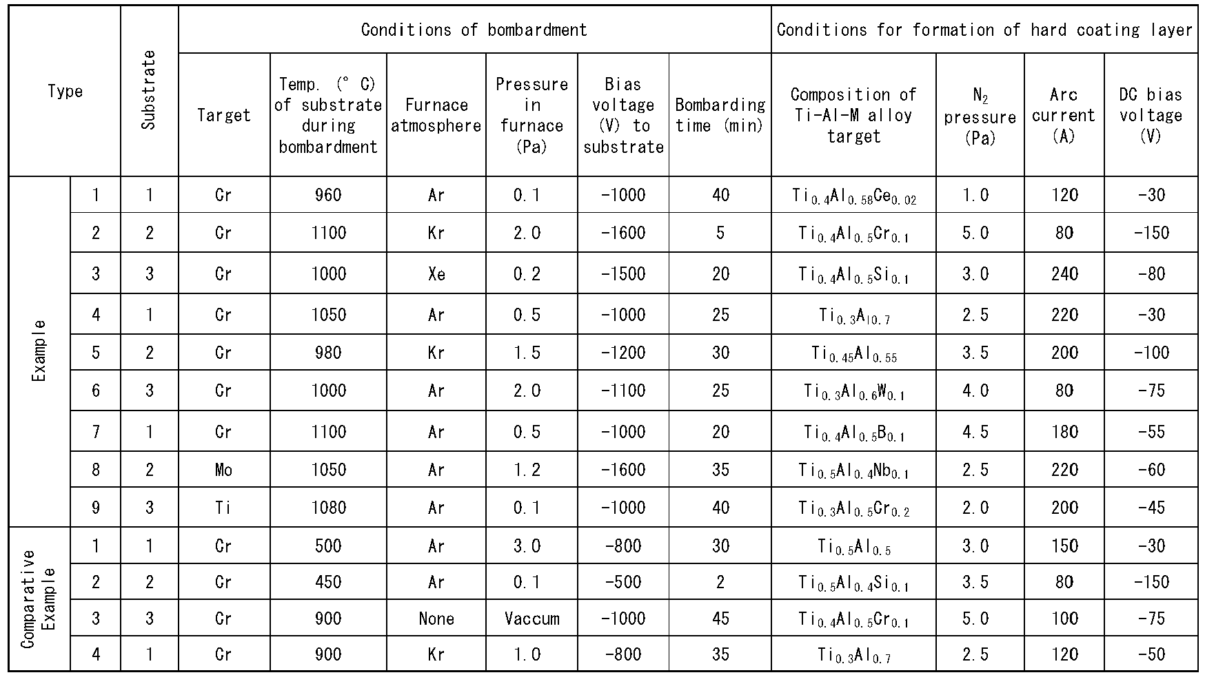


- The coated tools of Examples 1 to 9 and Comparative Examples 1 to 3 were subjected to single-blade front-face milling tests with a SE445R0506E cutter. A nickel alloy and a titanium alloy were served to high-speed milling tests under the following cutting conditions:
-
- Workpiece: A block of 60 mm wide by 200 mm long Ni-based alloy having a composition of Ni (base), 19% Cr, 18.5% Fe, 5.2% Cd, 5% Ta, 3% Mo, 0.9% Ti, 0.5% Al, 0.3% Si, 0.2% Mn, 0.05% Cu, and 0.04% C by mass.
- Cutting speed: 75 m/min.
- Cutting depth: 1.1 mm
- Feed: 0.09 mm/tooth.
- The results of the test is shown in Table 5.
-
- Workpiece: A 60 mm wide by 200 mm long block having a composition of Ti (base). 6% Al, and 4% V.
- Cutting speed: 90 m/min
- Cutting depth: 1.1 mm
- Feed: 0.09 mm/tooth
- The results of the test is shown in Table 6.


- The results shown in Tables 5 and 6 demonstrate that Examples 1 to 9 exhibit no abnormal damage, such as chipping or delamination, under either cutting condition A or B, indicating high welding resistance and chipping resistance.
- In contrast, Comparative Examples 1 to 3 have reached their lifetimes within a short time due to occurrence of chipping or progression of wear on the flank surface under both cutting conditions A and B.
- The disclosed embodiments are in all respects exemplary and not restrictive; the scope of the present invention is indicated by the claims, not by the embodiments, and is intended to include all variations within the meaning and scope of the claims and equivalents.
- The surface coated cutting tool of the present invention can be used not only for cutting of various steels under normal cutting conditions, but also for high-speed cutting of, for example, titanium alloys and nickel alloys involving high heat generation and high load applied to the cutting edge. The cutting tool exhibits high resistance against welding and chipping , and shows excellent cutting performance over a long period of time. Such cutting tool can accordingly respond to the higher performance of cutting machines, labor saving and energy saving in cutting processes, and cost reduction. Reference Signs List
-
- 1 substrate
- 2 binder phase
- 3 WC grain
- 4 interfacial layer
- 5 Region A
- 6 Region B
Claims (2)
- A surface coated cutting tool comprising a substrate and a coating layer on the substrate, the substrate comprising a WC-based cemented carbide comprising a hard phase component of WC grains and a binder phase primarily composed of Co, wherein(a) an interfacial layer is disposed between the substrate and the coating layer;(b) the interfacial layer includes a region A that has a W content WA and a C content CA directly above the hard phase component and a region B that has a W content WB and a C content CB directly above the binder phase, and the interfacial layer has an average thickness;at the midpoint across the average thickness of the interfacial layer, the W content WA in the region A is in the range of 90 to 99 mass%, while the W content WB in the region B is in the range of 30 to 65 mass%,the C content CA in the region A satisfies the expression: CA ≤ 0.05 mass%, andthe C content CB in the region B satisfies the expression: CA ≤ CB ≤ 0.09 mass%.
- The surface coated cutting tool set forth in Claim 1, wherein the region A further contains 1 to 10 mass% Cr, and the region B further contains 30 to 60 mass% Co and 5 to 10 mass% Cr.
Applications Claiming Priority (1)
| Application Number | Priority Date | Filing Date | Title |
|---|---|---|---|
| PCT/JP2021/013515 WO2022208654A1 (en) | 2021-03-30 | 2021-03-30 | Surface-coated cutting tool |
Publications (2)
| Publication Number | Publication Date |
|---|---|
| EP4316706A1 true EP4316706A1 (en) | 2024-02-07 |
| EP4316706A4 EP4316706A4 (en) | 2025-01-15 |
Family
ID=83455775
Family Applications (1)
| Application Number | Title | Priority Date | Filing Date |
|---|---|---|---|
| EP21934826.5A Pending EP4316706A4 (en) | 2021-03-30 | 2021-03-30 | SURFACE COATED CUTTING TOOL |
Country Status (5)
| Country | Link |
|---|---|
| US (1) | US20240165713A1 (en) |
| EP (1) | EP4316706A4 (en) |
| KR (1) | KR102865617B1 (en) |
| CN (1) | CN117062684A (en) |
| WO (1) | WO2022208654A1 (en) |
Family Cites Families (11)
| Publication number | Priority date | Publication date | Assignee | Title |
|---|---|---|---|---|
| DE19547305A1 (en) | 1995-12-18 | 1997-06-19 | Univ Sheffield | Coating metal substrates with titanium aluminium nitride for coating steel |
| CN100431756C (en) * | 2004-01-30 | 2008-11-12 | 三菱麻铁里亚尔株式会社 | Cutting tool made of surface-coated cemented carbide and method for manufacturing same |
| JP4776395B2 (en) * | 2006-02-24 | 2011-09-21 | 京セラ株式会社 | Cutting tools |
| JP2014152345A (en) | 2013-02-05 | 2014-08-25 | Hitachi Tool Engineering Ltd | Hard film coated wc based hard alloy member and method for producing the same |
| JP6331003B2 (en) * | 2013-11-07 | 2018-05-30 | 三菱マテリアル株式会社 | Surface coated cutting tool |
| JP6555796B2 (en) | 2014-09-26 | 2019-08-07 | 日立金属株式会社 | Coated cutting tool |
| JP6385233B2 (en) | 2014-10-10 | 2018-09-05 | 日立金属株式会社 | Coated cutting tool |
| JP7021528B2 (en) * | 2017-03-17 | 2022-02-17 | 株式会社Moldino | Cemented carbide and its manufacturing method, and cutting tools using it |
| WO2019138599A1 (en) * | 2018-01-09 | 2019-07-18 | 住友電工ハードメタル株式会社 | Super-hard alloy and cutting tool |
| JP7227472B2 (en) * | 2019-02-12 | 2023-02-22 | 三菱マテリアル株式会社 | hard coating cutting tools |
| WO2020184352A1 (en) * | 2019-03-14 | 2020-09-17 | 三菱マテリアル株式会社 | Surface-coated cutting tool |
-
2021
- 2021-03-30 US US18/282,610 patent/US20240165713A1/en active Pending
- 2021-03-30 WO PCT/JP2021/013515 patent/WO2022208654A1/en not_active Ceased
- 2021-03-30 KR KR1020237032545A patent/KR102865617B1/en active Active
- 2021-03-30 EP EP21934826.5A patent/EP4316706A4/en active Pending
- 2021-03-30 CN CN202180096305.5A patent/CN117062684A/en active Pending
Also Published As
| Publication number | Publication date |
|---|---|
| US20240165713A1 (en) | 2024-05-23 |
| KR20230162784A (en) | 2023-11-28 |
| WO2022208654A1 (en) | 2022-10-06 |
| EP4316706A4 (en) | 2025-01-15 |
| KR102865617B1 (en) | 2025-09-26 |
| CN117062684A (en) | 2023-11-14 |
Similar Documents
| Publication | Publication Date | Title |
|---|---|---|
| EP2982466B1 (en) | Surface-coated cutting tool | |
| EP3360632B1 (en) | Coated cutting tool | |
| JP7733444B2 (en) | Hard-coated cutting tools | |
| EP3456867A1 (en) | Coated drill | |
| EP3219420B1 (en) | Surface-coated cutting tool | |
| EP4295978A1 (en) | Surface-coated cutting tool | |
| JP2021088039A (en) | Surface coating-cutting tool | |
| JP5035956B2 (en) | Surface-coated cutting tool with excellent fracture resistance due to hard coating layer | |
| JP7492683B2 (en) | Surface-coated cutting tools | |
| JP2011240438A (en) | Surface coated cutting tool excellent in heat resistance and fusion resistance | |
| EP4309835A1 (en) | Surface-coated cutting tool | |
| US20240165713A1 (en) | Surface-coated cutting tool | |
| JP2020127998A (en) | Hard coat cutting tool | |
| JP2020142312A (en) | Surface coating cutting tool | |
| JP7375592B2 (en) | surface coated cutting tools | |
| EP4464441A1 (en) | Surface-coated cutting tool | |
| JP4771198B2 (en) | Surface-coated cermet cutting tool with excellent wear resistance due to high-hardness coating in high-reactive work materials | |
| EP4678314A1 (en) | Coated cutting tool | |
| JP2021088038A (en) | Surface coating-cutting tool | |
| JP7816921B2 (en) | surface coated cutting tools | |
| JP4379911B2 (en) | Surface coated cemented carbide cutting tool with excellent wear resistance with hard coating layer in high speed cutting | |
| JP4158191B2 (en) | A method of forming a hard coating layer on the surface of a cutting tool that exhibits excellent chipping resistance and wear resistance under high-speed heavy cutting conditions | |
| JP4844879B2 (en) | Surface coated cutting tool with excellent wear resistance with hard coating layer in high speed cutting of heat resistant alloy | |
| JP4379912B2 (en) | Surface coated cemented carbide cutting tool with excellent wear resistance with hard coating layer in high speed cutting | |
| JP7025693B2 (en) | Surface covering cutting tool |
Legal Events
| Date | Code | Title | Description |
|---|---|---|---|
| STAA | Information on the status of an ep patent application or granted ep patent |
Free format text: STATUS: THE INTERNATIONAL PUBLICATION HAS BEEN MADE |
|
| PUAI | Public reference made under article 153(3) epc to a published international application that has entered the european phase |
Free format text: ORIGINAL CODE: 0009012 |
|
| STAA | Information on the status of an ep patent application or granted ep patent |
Free format text: STATUS: REQUEST FOR EXAMINATION WAS MADE |
|
| 17P | Request for examination filed |
Effective date: 20231024 |
|
| AK | Designated contracting states |
Kind code of ref document: A1 Designated state(s): AL AT BE BG CH CY CZ DE DK EE ES FI FR GB GR HR HU IE IS IT LI LT LU LV MC MK MT NL NO PL PT RO RS SE SI SK SM TR |
|
| DAV | Request for validation of the european patent (deleted) | ||
| DAX | Request for extension of the european patent (deleted) | ||
| REG | Reference to a national code |
Ref country code: DE Ref legal event code: R079 Free format text: PREVIOUS MAIN CLASS: B23B0027140000 Ipc: C22C0029080000 |
|
| A4 | Supplementary search report drawn up and despatched |
Effective date: 20241212 |
|
| RIC1 | Information provided on ipc code assigned before grant |
Ipc: C22C 1/051 20230101ALN20241206BHEP Ipc: B22F 5/00 20060101ALN20241206BHEP Ipc: B22F 3/24 20060101ALN20241206BHEP Ipc: C23C 14/32 20060101ALI20241206BHEP Ipc: C23C 14/06 20060101ALI20241206BHEP Ipc: C23C 14/02 20060101ALI20241206BHEP Ipc: C22C 29/08 20060101AFI20241206BHEP |