EP4316642A1 - Reaction system and method for preparing butyraldehyde by propylene carbonylation - Google Patents
Reaction system and method for preparing butyraldehyde by propylene carbonylation Download PDFInfo
- Publication number
- EP4316642A1 EP4316642A1 EP21934361.3A EP21934361A EP4316642A1 EP 4316642 A1 EP4316642 A1 EP 4316642A1 EP 21934361 A EP21934361 A EP 21934361A EP 4316642 A1 EP4316642 A1 EP 4316642A1
- Authority
- EP
- European Patent Office
- Prior art keywords
- gas
- micro
- propylene
- reactor
- inlet
- Prior art date
- Legal status (The legal status is an assumption and is not a legal conclusion. Google has not performed a legal analysis and makes no representation as to the accuracy of the status listed.)
- Pending
Links
- ZTQSAGDEMFDKMZ-UHFFFAOYSA-N Butyraldehyde Chemical compound CCCC=O ZTQSAGDEMFDKMZ-UHFFFAOYSA-N 0.000 title claims abstract description 106
- QQONPFPTGQHPMA-UHFFFAOYSA-N propylene Natural products CC=C QQONPFPTGQHPMA-UHFFFAOYSA-N 0.000 title claims abstract description 88
- 125000004805 propylene group Chemical group [H]C([H])([H])C([H])([*:1])C([H])([H])[*:2] 0.000 title claims abstract description 86
- 238000006243 chemical reaction Methods 0.000 title claims abstract description 71
- HGBOYTHUEUWSSQ-UHFFFAOYSA-N valeric aldehyde Natural products CCCCC=O HGBOYTHUEUWSSQ-UHFFFAOYSA-N 0.000 title claims abstract description 31
- 238000005810 carbonylation reaction Methods 0.000 title claims abstract description 23
- 230000006315 carbonylation Effects 0.000 title claims abstract description 20
- 238000000034 method Methods 0.000 title claims description 12
- 238000003786 synthesis reaction Methods 0.000 claims abstract description 69
- 230000015572 biosynthetic process Effects 0.000 claims abstract description 66
- 239000002904 solvent Substances 0.000 claims abstract description 39
- 239000003054 catalyst Substances 0.000 claims abstract description 38
- 239000002994 raw material Substances 0.000 claims abstract description 10
- 239000007789 gas Substances 0.000 claims description 112
- 239000007788 liquid Substances 0.000 claims description 40
- 238000003860 storage Methods 0.000 claims description 40
- 239000007791 liquid phase Substances 0.000 claims description 27
- 239000012071 phase Substances 0.000 claims description 27
- 239000000047 product Substances 0.000 claims description 24
- 238000000926 separation method Methods 0.000 claims description 18
- UGFAIRIUMAVXCW-UHFFFAOYSA-N Carbon monoxide Chemical compound [O+]#[C-] UGFAIRIUMAVXCW-UHFFFAOYSA-N 0.000 claims description 12
- AMIMRNSIRUDHCM-UHFFFAOYSA-N Isopropylaldehyde Chemical compound CC(C)C=O AMIMRNSIRUDHCM-UHFFFAOYSA-N 0.000 claims description 12
- 229910002091 carbon monoxide Inorganic materials 0.000 claims description 12
- 239000001257 hydrogen Substances 0.000 claims description 12
- 229910052739 hydrogen Inorganic materials 0.000 claims description 12
- UFHFLCQGNIYNRP-UHFFFAOYSA-N Hydrogen Chemical compound [H][H] UFHFLCQGNIYNRP-UHFFFAOYSA-N 0.000 claims description 10
- 238000002485 combustion reaction Methods 0.000 claims description 8
- 239000012043 crude product Substances 0.000 claims description 6
- 125000002887 hydroxy group Chemical group [H]O* 0.000 claims description 4
- 229910052703 rhodium Inorganic materials 0.000 claims description 4
- 239000010948 rhodium Substances 0.000 claims description 4
- MHOVAHRLVXNVSD-UHFFFAOYSA-N rhodium atom Chemical group [Rh] MHOVAHRLVXNVSD-UHFFFAOYSA-N 0.000 claims description 3
- 238000000746 purification Methods 0.000 claims description 2
- 238000002156 mixing Methods 0.000 claims 1
- 238000005265 energy consumption Methods 0.000 abstract description 6
- 238000007086 side reaction Methods 0.000 abstract description 2
- 230000000694 effects Effects 0.000 description 9
- 239000000203 mixture Substances 0.000 description 8
- IJGRMHOSHXDMSA-UHFFFAOYSA-N Atomic nitrogen Chemical compound N#N IJGRMHOSHXDMSA-UHFFFAOYSA-N 0.000 description 4
- LRHPLDYGYMQRHN-UHFFFAOYSA-N N-Butanol Chemical compound CCCCO LRHPLDYGYMQRHN-UHFFFAOYSA-N 0.000 description 4
- ATUOYWHBWRKTHZ-UHFFFAOYSA-N Propane Chemical compound CCC ATUOYWHBWRKTHZ-UHFFFAOYSA-N 0.000 description 4
- RIOQSEWOXXDEQQ-UHFFFAOYSA-N triphenylphosphine Chemical compound C1=CC=CC=C1P(C=1C=CC=CC=1)C1=CC=CC=C1 RIOQSEWOXXDEQQ-UHFFFAOYSA-N 0.000 description 4
- 238000009827 uniform distribution Methods 0.000 description 4
- 238000009835 boiling Methods 0.000 description 3
- 238000010586 diagram Methods 0.000 description 3
- 239000006185 dispersion Substances 0.000 description 3
- 238000009826 distribution Methods 0.000 description 3
- 230000006872 improvement Effects 0.000 description 3
- 239000000463 material Substances 0.000 description 3
- 238000002360 preparation method Methods 0.000 description 3
- 230000008569 process Effects 0.000 description 3
- 230000009471 action Effects 0.000 description 2
- 230000009286 beneficial effect Effects 0.000 description 2
- 230000008901 benefit Effects 0.000 description 2
- 150000002431 hydrogen Chemical class 0.000 description 2
- ZXEKIIBDNHEJCQ-UHFFFAOYSA-N isobutanol Chemical compound CC(C)CO ZXEKIIBDNHEJCQ-UHFFFAOYSA-N 0.000 description 2
- 238000004519 manufacturing process Methods 0.000 description 2
- 230000004048 modification Effects 0.000 description 2
- 238000012986 modification Methods 0.000 description 2
- 229910052757 nitrogen Inorganic materials 0.000 description 2
- 239000001294 propane Substances 0.000 description 2
- 239000000126 substance Substances 0.000 description 2
- XMVBHZBLHNOQON-UHFFFAOYSA-N 2-butyl-1-octanol Chemical compound CCCCCCC(CO)CCCC XMVBHZBLHNOQON-UHFFFAOYSA-N 0.000 description 1
- IDYWQONQVXWFQP-UHFFFAOYSA-N butan-1-ol;octan-1-ol Chemical compound CCCCO.CCCCCCCCO IDYWQONQVXWFQP-UHFFFAOYSA-N 0.000 description 1
- 239000007795 chemical reaction product Substances 0.000 description 1
- 239000003153 chemical reaction reagent Substances 0.000 description 1
- 230000008878 coupling Effects 0.000 description 1
- 238000010168 coupling process Methods 0.000 description 1
- 238000005859 coupling reaction Methods 0.000 description 1
- 230000007423 decrease Effects 0.000 description 1
- 238000005516 engineering process Methods 0.000 description 1
- 239000002360 explosive Substances 0.000 description 1
- 239000012847 fine chemical Substances 0.000 description 1
- 239000012530 fluid Substances 0.000 description 1
- 230000033444 hydroxylation Effects 0.000 description 1
- 238000005805 hydroxylation reaction Methods 0.000 description 1
- GNPXKHTZVDUNOY-UHFFFAOYSA-N oxomethylidenerhodium Chemical compound O=C=[Rh] GNPXKHTZVDUNOY-UHFFFAOYSA-N 0.000 description 1
- 238000010992 reflux Methods 0.000 description 1
- 238000005728 strengthening Methods 0.000 description 1
- XLYOFNOQVPJJNP-UHFFFAOYSA-N water Substances O XLYOFNOQVPJJNP-UHFFFAOYSA-N 0.000 description 1
Images

Classifications
-
- B—PERFORMING OPERATIONS; TRANSPORTING
- B01—PHYSICAL OR CHEMICAL PROCESSES OR APPARATUS IN GENERAL
- B01J—CHEMICAL OR PHYSICAL PROCESSES, e.g. CATALYSIS OR COLLOID CHEMISTRY; THEIR RELEVANT APPARATUS
- B01J8/00—Chemical or physical processes in general, conducted in the presence of fluids and solid particles; Apparatus for such processes
- B01J8/08—Chemical or physical processes in general, conducted in the presence of fluids and solid particles; Apparatus for such processes with moving particles
- B01J8/12—Chemical or physical processes in general, conducted in the presence of fluids and solid particles; Apparatus for such processes with moving particles moved by gravity in a downward flow
-
- C—CHEMISTRY; METALLURGY
- C07—ORGANIC CHEMISTRY
- C07C—ACYCLIC OR CARBOCYCLIC COMPOUNDS
- C07C45/00—Preparation of compounds having >C = O groups bound only to carbon or hydrogen atoms; Preparation of chelates of such compounds
- C07C45/49—Preparation of compounds having >C = O groups bound only to carbon or hydrogen atoms; Preparation of chelates of such compounds by reaction with carbon monoxide
- C07C45/50—Preparation of compounds having >C = O groups bound only to carbon or hydrogen atoms; Preparation of chelates of such compounds by reaction with carbon monoxide by oxo-reactions
-
- B—PERFORMING OPERATIONS; TRANSPORTING
- B01—PHYSICAL OR CHEMICAL PROCESSES OR APPARATUS IN GENERAL
- B01J—CHEMICAL OR PHYSICAL PROCESSES, e.g. CATALYSIS OR COLLOID CHEMISTRY; THEIR RELEVANT APPARATUS
- B01J8/00—Chemical or physical processes in general, conducted in the presence of fluids and solid particles; Apparatus for such processes
- B01J8/0015—Feeding of the particles in the reactor; Evacuation of the particles out of the reactor
- B01J8/004—Feeding of the particles in the reactor; Evacuation of the particles out of the reactor by means of a nozzle
-
- B—PERFORMING OPERATIONS; TRANSPORTING
- B01—PHYSICAL OR CHEMICAL PROCESSES OR APPARATUS IN GENERAL
- B01J—CHEMICAL OR PHYSICAL PROCESSES, e.g. CATALYSIS OR COLLOID CHEMISTRY; THEIR RELEVANT APPARATUS
- B01J8/00—Chemical or physical processes in general, conducted in the presence of fluids and solid particles; Apparatus for such processes
- B01J8/08—Chemical or physical processes in general, conducted in the presence of fluids and solid particles; Apparatus for such processes with moving particles
- B01J8/082—Controlling processes
-
- B—PERFORMING OPERATIONS; TRANSPORTING
- B01—PHYSICAL OR CHEMICAL PROCESSES OR APPARATUS IN GENERAL
- B01J—CHEMICAL OR PHYSICAL PROCESSES, e.g. CATALYSIS OR COLLOID CHEMISTRY; THEIR RELEVANT APPARATUS
- B01J8/00—Chemical or physical processes in general, conducted in the presence of fluids and solid particles; Apparatus for such processes
- B01J8/08—Chemical or physical processes in general, conducted in the presence of fluids and solid particles; Apparatus for such processes with moving particles
- B01J8/085—Feeding reactive fluids
-
- C—CHEMISTRY; METALLURGY
- C07—ORGANIC CHEMISTRY
- C07C—ACYCLIC OR CARBOCYCLIC COMPOUNDS
- C07C29/00—Preparation of compounds having hydroxy or O-metal groups bound to a carbon atom not belonging to a six-membered aromatic ring
- C07C29/132—Preparation of compounds having hydroxy or O-metal groups bound to a carbon atom not belonging to a six-membered aromatic ring by reduction of an oxygen containing functional group
- C07C29/136—Preparation of compounds having hydroxy or O-metal groups bound to a carbon atom not belonging to a six-membered aromatic ring by reduction of an oxygen containing functional group of >C=O containing groups, e.g. —COOH
- C07C29/14—Preparation of compounds having hydroxy or O-metal groups bound to a carbon atom not belonging to a six-membered aromatic ring by reduction of an oxygen containing functional group of >C=O containing groups, e.g. —COOH of a —CHO group
- C07C29/141—Preparation of compounds having hydroxy or O-metal groups bound to a carbon atom not belonging to a six-membered aromatic ring by reduction of an oxygen containing functional group of >C=O containing groups, e.g. —COOH of a —CHO group with hydrogen or hydrogen-containing gases
-
- C—CHEMISTRY; METALLURGY
- C07—ORGANIC CHEMISTRY
- C07C—ACYCLIC OR CARBOCYCLIC COMPOUNDS
- C07C45/00—Preparation of compounds having >C = O groups bound only to carbon or hydrogen atoms; Preparation of chelates of such compounds
- C07C45/49—Preparation of compounds having >C = O groups bound only to carbon or hydrogen atoms; Preparation of chelates of such compounds by reaction with carbon monoxide
- C07C45/50—Preparation of compounds having >C = O groups bound only to carbon or hydrogen atoms; Preparation of chelates of such compounds by reaction with carbon monoxide by oxo-reactions
- C07C45/505—Asymmetric hydroformylation
-
- B—PERFORMING OPERATIONS; TRANSPORTING
- B01—PHYSICAL OR CHEMICAL PROCESSES OR APPARATUS IN GENERAL
- B01J—CHEMICAL OR PHYSICAL PROCESSES, e.g. CATALYSIS OR COLLOID CHEMISTRY; THEIR RELEVANT APPARATUS
- B01J2208/00—Processes carried out in the presence of solid particles; Reactors therefor
- B01J2208/00008—Controlling the process
- B01J2208/00017—Controlling the temperature
-
- B—PERFORMING OPERATIONS; TRANSPORTING
- B01—PHYSICAL OR CHEMICAL PROCESSES OR APPARATUS IN GENERAL
- B01J—CHEMICAL OR PHYSICAL PROCESSES, e.g. CATALYSIS OR COLLOID CHEMISTRY; THEIR RELEVANT APPARATUS
- B01J2208/00—Processes carried out in the presence of solid particles; Reactors therefor
- B01J2208/00008—Controlling the process
- B01J2208/00539—Pressure
-
- B—PERFORMING OPERATIONS; TRANSPORTING
- B01—PHYSICAL OR CHEMICAL PROCESSES OR APPARATUS IN GENERAL
- B01J—CHEMICAL OR PHYSICAL PROCESSES, e.g. CATALYSIS OR COLLOID CHEMISTRY; THEIR RELEVANT APPARATUS
- B01J2208/00—Processes carried out in the presence of solid particles; Reactors therefor
- B01J2208/00796—Details of the reactor or of the particulate material
- B01J2208/00893—Feeding means for the reactants
- B01J2208/00902—Nozzle-type feeding elements
-
- B—PERFORMING OPERATIONS; TRANSPORTING
- B01—PHYSICAL OR CHEMICAL PROCESSES OR APPARATUS IN GENERAL
- B01J—CHEMICAL OR PHYSICAL PROCESSES, e.g. CATALYSIS OR COLLOID CHEMISTRY; THEIR RELEVANT APPARATUS
- B01J2208/00—Processes carried out in the presence of solid particles; Reactors therefor
- B01J2208/00796—Details of the reactor or of the particulate material
- B01J2208/00893—Feeding means for the reactants
- B01J2208/00911—Sparger-type feeding elements
-
- C—CHEMISTRY; METALLURGY
- C07—ORGANIC CHEMISTRY
- C07C—ACYCLIC OR CARBOCYCLIC COMPOUNDS
- C07C2523/00—Catalysts comprising metals or metal oxides or hydroxides, not provided for in group C07C2521/00
- C07C2523/38—Catalysts comprising metals or metal oxides or hydroxides, not provided for in group C07C2521/00 of noble metals
- C07C2523/40—Catalysts comprising metals or metal oxides or hydroxides, not provided for in group C07C2521/00 of noble metals of the platinum group metals
- C07C2523/46—Ruthenium, rhodium, osmium or iridium
-
- Y—GENERAL TAGGING OF NEW TECHNOLOGICAL DEVELOPMENTS; GENERAL TAGGING OF CROSS-SECTIONAL TECHNOLOGIES SPANNING OVER SEVERAL SECTIONS OF THE IPC; TECHNICAL SUBJECTS COVERED BY FORMER USPC CROSS-REFERENCE ART COLLECTIONS [XRACs] AND DIGESTS
- Y02—TECHNOLOGIES OR APPLICATIONS FOR MITIGATION OR ADAPTATION AGAINST CLIMATE CHANGE
- Y02P—CLIMATE CHANGE MITIGATION TECHNOLOGIES IN THE PRODUCTION OR PROCESSING OF GOODS
- Y02P20/00—Technologies relating to chemical industry
- Y02P20/50—Improvements relating to the production of bulk chemicals
- Y02P20/584—Recycling of catalysts
Definitions
- the present invention relates to the technical field of reaction preparation of propylene hydroxylation, in particular to a reaction system for preparing butyraldehyde by propylene carbonylation and a method thereof.
- Butyl octanol is an important raw material for the synthesis of fine chemical products, and the preparation of n-butyraldehyde is the most important part in the process of preparing butanol octanol,
- the generation of butyraldehyde mainly takes synthesis gas and propylene as raw materials, and the rhodium carbonyl/triphenylphosphine complex is used as a catalyst to react to generate mixed butyraldehyde, which is further rectified to obtain a butyraldehyde mixture after separating the catalyst.
- a first objective of the present invention is to provide a reaction system for preparing butyraldehyde by propylene carbonylation.
- the reaction system disperses and breaks the material into micro-bubbles by disposing a micro-interface generator inside the reactor, thereby increasing the phase boundary area between the gas-phase and the liquid-phase. Therefore, the mas transfer space is fully satisfied, the residence time of the gas in the liquid-phase is increased, the energy consumption is reduced, and reaction efficiency is improved.
- the operation temperature and the operation pressure inside the reactor are reduced, and the safety and stability of the entire reaction system are improved.
- a second objective of the present invention is to provide a reaction method for preparing butyraldehyde using the above-mentioned reaction system for preparing butyraldehyde by propylene carbonylation.
- the reaction method is simple and convenient to operate, and the obtained n-butyraldehyde has high purity and high product quality, which is beneficial to reduce energy consumption, and achieves a better reaction effect than the existing process.
- the present invention provides a reaction system for preparing butyraldehyde by propylene carbonylation, including; a reactor, a propylene storage tank, a carbon monoxide storage tank, a hydrogen storage tank, a propylene pipeline and a synthesis gas pipeline.
- the side wall of the reactor is provided with a catalyst inlet, a propylene inlet and a synthesis gas inlet sequentially from top to bottom, and the bottom of the reactor is provided with a solvent inlet.
- the inside of the reactor is provided with two micro-interface generators from top to bottom, the micro-interface generator located at the top is connected with the propylene inlet to break the propylene gas into micron-scale micro-bubbles; the micro-interface generator located at the bottom is connected with the synthesis gas inlet for breaking the synthesis gas into micron-scale micro-bubbles; the outlets of the two-interface generators are opposite, and both the outlets are connected with a gas distributor for evenly distributing raw materials.
- the carbon monoxide storage tank is connected in parallel with the hydrogen storage tank, and both the carbon monoxide storage tank and the hydrogen storage tank are connected to the synthesis gas inlet through the synthesis gas pipeline; both the propylene pipeline and the synthesis gas pipeline are provided with bubble generators for pre-dispersing and breaking the gas into bubbles.
- butyraldehyde mainly takes synthesis gas and propylene as raw materials, and it uses carbonyl rhodium/triphenylphosphine complex as a catalyst to generate a mixed butyraldehyde. After the catalyst is separated from the mixed butyraldehyde, further rectification is performed to obtain a butyraldehyde mixture, and then the butyraldehyde mixture is subjected to isomer separation to obtain n-butyraldehyde.
- the invention provides a reaction system for preparing butyraldehyde by propylene carbonylation.
- the reaction system disperses and breaks propylene and synthesis gas by disposing two micro-interface generators inside the reactor, which improves the mass transfer effect, greatly increases the mass transfer rate, and reduces the required reaction temperature and reaction pressure.
- the propylene micro-bubbles and synthesis gas micro-bubbles can have a hedging effect to realize the uniform distribution of the micro-bubbles.
- a gas distributor at the outlet of the micro-interface generators, the micro-bubbles are further distributed evenly.
- the raw material gas is pre-broken, and the gas is broken into large bubbles before the gas is dispersed into micro-bubbles, and the micro-interface generators breaks these large bubbles into micro-bubbles, which improves the generation efficiency of the micro-bubbles.
- the upper micro-interface generator is connected to the propylene inlet
- the lower micro-interface generator is connected to the synthesis gas inlet.
- the gas source of synthesis gas needs to be synthesized in advance, and the raw materials are all flammable and explosive gases.
- the raw materials are all flammable and explosive gases.
- the micro-interface generator for breaking propylene is disposed at the top, and the micro-interface generator for breaking synthesis gas is disposed at the bottom, such an arrangement also fully considers various factors such as safety and reaction efficiency.
- the synthesis gas is fully broken and dispersed by the micro-interface generator, it will also pass through the gas distributor located on the top of the micro-interface generator with a higher probability to achieve a more uniform distribution.
- the gas distributor includes a distributor body and a plurality of nozzles; and the plurality of nozzles are obliquely arranged on the distributor body to uniformly disperse the micro-bubbles generated by the micro-interface generator.
- the purpose of the oblique arrangement is also to make the bubbles more dispersed, and the dispersed tile area is larger and more dispersed, thereby further improving the reaction efficiency.
- the gas distributors are arranged at the gas outlets of each micro-interface generator to ensure that all the micro-interface generators seamlessly enter the distributor body and are sprayed out through the plurality of nozzles.
- the micro-interface generators and the gas distributor are used in cooperation to ensure the dispersion and crushing of the gas, and at the same time, to improve the utilization rate of each micro-bubble through gas distribution, and to avoid the disordered state of the micro-bubbles from being unfavorable to the smooth progress of the reaction.
- the disposition positions of the micro-interface generators and the connection and arrangement of the gas distributors have been obtained through a lot of practice.
- the bubble generator includes a gas-phase main channel and a liquid-phase branch channel.
- the liquid-phase branch channel is connected to the reactor, and the solvent in the reactor enters the gas-phase main channel through the liquid-phase branch channel and mixes with the gas in the gas-phase main channel to form bubbles.
- a catalyst inlet is disposed on the side wall of the reactor, and a sprayer is disposed in the reactor.
- the sprayer is located above the micro-interface generator; the sprayer is connected to the catalyst inlet; and the catalyst inlet is connected with a catalyst storage tank.
- the catalyst is sprayed through the sprayer, which improves the reaction effect and makes the catalyst distribution more uniform.
- two micro-interface generators are disposed in the reactor, which are respectively connected to the propylene inlet and the synthesis gas inlet.
- the reactor is first filled with solvent, so that the two micro-interface generators are immersed in the solvent, the propylene is dispersed and broken into large propylene bubbles in the bubble generator, and the large propylene bubbles enter into the micro-interface generator through the propylene inlet.
- the micro-interface generator further disperses and breaks into micron-scale micro-bubbles.
- the synthesis gas is dispersed and broken into large synthesis gas bubbles in the bubble generator, and the large synthesis gas bubbles enter the micro-interface generator through the synthesis gas inlet, and then is further dispersed and broken into micron-scale micro-bubbles in the micro-interface generator.
- the solvent provides a liquid-phase medium for the dispersion and crushing of propylene and synthesis gas.
- Propylene and synthesis gas are respectively subjected to a micro-interface generator, which improves the efficiency of dispersion and crushing.
- the outlets of the two micro-interface generators are facing each other, which can play a hedging effect to achieve uniform distribution of micro-bubbles.
- a gas distributor is disposed at the outlet of the micro-interface generator, and the generated micro-bubbles are sprayed in different directions through the plurality of nozzles on the gas distributor, so that the running direction of the micro-bubbles is changed, and the micro-bubbles are distributed more evenly.
- the present invention improves the application effect of the micro-interface generator itself by combining the application of the bubble generator, the micro-interface generator and the gas distributor.
- micro-interface generator used in the present invention has been embodied in the inventor's previous patents, such as patent applications with application numbers CN201610641119.6 , CN201610641251.7 , CN201710766435.0 , CN106187660 , and CN105903425A , and patents with patent numbers CN109437390A , CN205833127U and CN207581700U .
- the specific product structure and working principle of the micro-bubble generator that is, the micro-interface generator
- the micro-bubble generator includes a main body and a secondary crushing component, the main body has a cavity, the main body is provided with an inlet communicating with the cavity, and the opposite first end and second end of the cavity are open, wherein the cross-sectional area of the cavity decreases from the middle of the cavity to the first end and the second end of the cavity.
- the secondary crushing component is arranged on at least one of the first end and the second end of the cavity. Apart of the secondary crushing component is disposed in the cavity, and an annular channel is formed between the secondary crushing component and the through holes opened at both the first end and the second end of the cavity.
- the micro-bubble generator also includes an air inlet pipe and a liquid inlet pipe.
- the liquid enters the micro-bubble generator tangentially through the liquid inlet pipe, rotates at ultra-high speed and cuts the gas, so that the gas bubbles are broken into micron-scale micro-bubbles, thereby the mass transfer area between the liquid-phase and the gas-phase is increased.
- the micro-bubble generator in this patent is a pneumatic micro-interface generator.
- the primary bubble breaker has a circulation liquid inlet, a circulation gas inlet, and a gas-liquid mixture outlet, while the secondary bubble breaker connects the feed port with the gas-liquid mixture outlet, which indicates that the bubble breaker needs to mix gas and liquid to enter.
- the primary bubble breaker mainly uses circulating fluid as power, so in fact, the primary bubble breaker belongs to the hydraulic micro-interface generator.
- the secondary bubble breaker simultaneously feeds the gas-liquid mixture into the elliptical rotating ball for rotation, so that the bubbles are broken during the rotation.
- the secondary bubble breaker is actually a gas-liquid linkage micro-interface generator.
- micro-interface generator which belongs to a specific form of a micro-interface generator.
- the micro-interface generator adopted in the present invention is not limited to the above-mentioned several forms.
- the specific structure of the bubble breaker described in the prior patents is only one of the forms that can be adopted by the micro-interface generator of the present invention.
- the entrainment power is provided by the liquid-phase coming in from the top, so as to achieve the effect of crushing into ultra-fine bubbles. It can also be seen from the drawings that the bubble breaker has a conical structure, and the diameter of the upper part is larger than that of the lower part, which also helps the liquid-phase to provide better entrainment power.
- micro-interface generator Since the micro-interface generator was just developed in the initial stages of the patent application, it was names micro-bubble generator (( CN201610641119.6 ) and bubble breaker ( 201710766435.0 ), etc. With the continuous improvement of technology, it was later renamed as micro-interface generator. Now the micro-interface generator in the present invention is equivalent to the previous micro-bubble generator, bubble breaker, etc., but their names are different. In summary, the micro-interface generator of the present invention belongs to the prior art.
- the top of the reactor is connected with a first condenser; the non-condensable gas outlet of the first condenser is connected with a combustion system, and the condensate outlet of the first condenser is connected with the reactor.
- the tail gas at the top of the reactor is condensed by the first condenser, and high-boiling substances such as n-butyraldehyde/isobutyraldehyde are condensed into liquids and returned to the reactor.
- Non-condensable gases such as nitrogen, hydrogen, propane, and carbon monoxide enter the combustion system for combustion and removal.
- a solvent inlet is disposed at the bottom of the reactor, and the solvent inlet is connected to a solvent storage tank.
- the solvent in the solvent storage tank flows into the reactor through the solvent inlet to provide a medium for the reaction.
- the solvent is n-butyraldehyde or isobutyraldehyde.
- the reactor is provided with a product outlet, and the product outlet is connected with a demister.
- the demister is sequentially connected with a gas-liquid separator, an isomer separator tower and a rectification tower.
- the rectification tower is connected with a n-butyraldehyde storage tank. The demister captures the small liquid droplets entrained in the gas flow from the reactor and returns them to the reactor.
- a second condenser is disposed between the demister and the gas-liquid separator.
- the product defoamed by the demister is condensed by the second condenser and flows into the gas-liquid separator.
- the second condenser condenses the gas-phase product and flows into the gas-liquid separator.
- the gas-liquid separator is also connected with a third condenser, and the third condenser is connected with the micro-interface generator located at the top of the reactor.
- a part of the product separated by the gas-liquid separator directly flows into the isomer separation tower, and another part of the product flows back into the reactor after being condensed by the third condenser.
- a circulation pump is disposed at the outlet of the gas-liquid separator, and the liquid-phase stream at the bottom of the gas-liquid separator enters the circulation pump to raise the pressure.
- a part of the material at the outlet of the circulation pump flows into the isomer separation tower as a crude product, and the other part is cooled by the third condenser to about 80°C and returned to the micro-interface generator in the reactor to continue to participate in the reaction.
- the present invention also provides a reaction method using the above-mentioned reaction system for preparing butyraldehyde by propylene carbonylation, including the following steps: After dispersing and crushing propylene and synthesis gas through the micro-interface generators respectively, they are mixed with catalysts to carry out hydroxyl synthesis reaction, and then the crude product is obtained after defoaming and condensing gas-liquid separation. A separation of the crude product is performed to separate out n-butyraldehyde and isobutyraldehyde, and n-butyraldehyde is obtained after rectification and purification.
- the hydroxyl synthesis reaction temperature is 85-90° C, and the reaction pressure is 1.1-1.8 MPa.
- the catalyst is a rhodium catalyst.
- the reaction method disperses and crushes the propylene and the synthesis gas by disposing micro-interface generators inside the reactor. Therefore, before the carbonylation reaction of the propylene and the synthesis gas, they are broken into micro-bubbles with a diameter greater than or equal to 1 ⁇ m and less than lmm, such that the mass transfer area of the phase boundary is increased, the solubility of propylene and synthesis gas in the solvent is increased, the reaction pressure is reduced, and the reaction efficient is improved.
- the n-butanol product obtained by adopting the reaction method of the present invention has excellent quality and high yield. Moreover, the preparation method itself has low reaction temperature, greatly reduced pressure, and significantly reduced cost.
- the beneficial effects of the present invention include:
- connection should be understood in a broad sense.
- it can be a fixed connection, a detachable connection, or an integral connection; it can be a mechanical connection or an electrical connection; it can be a direct connection or an indirect connection through an intermediary, and it can be the internal connection between two components.
- connection can be a fixed connection, a detachable connection, or an integral connection; it can be a mechanical connection or an electrical connection; it can be a direct connection or an indirect connection through an intermediary, and it can be the internal connection between two components.
- a reaction system for preparing butyraldehyde by propylene carbonylation which includes: a reactor 10, a propylene storage tank 150, a carbon monoxide storage tank 130, a hydrogen storage tank 140, a propylene pipeline 200 and a synthesis gas pipeline 210.
- the side wall of the reactor 10 is provided with a propylene inlet 102 and a synthesis gas inlet 101 sequentially from top to bottom.
- the propylene inlet 102 is connected to the propylene storage tank 150 through the propylene pipeline 200; the carbon monoxide storage tank 130 is connected in parallel with the hydrogen storage tank 140, and both of them are connected to the synthesis gas inlet 101 through the synthesis gas pipeline 210.
- Both the propylene pipeline 200 and the synthesis gas pipeline 210 are provided with a bubble generator 190 for pre-dispersing and breaking the gas into bubbles.
- the bubble generator 190 includes a gas-phase main channel 1901 and a liquid-phase branch channel 1902; the liquid-phase branch channel 1902 is connected with the reactor 10, and the solvent in the reactor 10 enters the gas-phase main channel 1901 through the liquid-phase branch channel and mixes with the gas in the gas-phase main channel 1901 to form bubbles.
- propylene enters the gas-phase main channel 1901 of the bubble generator 190 through the propylene pipeline 200, and the solvent in the reactor 10 enters the gas-phase main channel 1901 through the liquid-phase branch channel 1902, and mixes with the propylene in the gas-phase main channel 1901 to form propylene bubbles, the propylene bubbles and the remaining solvent flow back into the reactor 10 from the propylene inlet 102.
- the synthesis gas enters the gas-phase main channel 1901 of the bubble generator 190 through the synthesis gas pipeline 210, and the solvent in the reactor 10 enters the gas-phase main channel 1901 through the liquid-phase branch channel 1902, and mixes with he synthesis gas in the gas-phase main channel 1901 to form synthesis gas bubbles, propylene bubbles and the remaining solvent flow back into the reactor 10 form the propylene inlet 102.
- a water pump is arranged at the inlet of the liquid-phase branch channel 1902 to pump the solvent to the liquid-phase branch channel 1902.
- the interior of the reactor 10 is provided with two micro-interface generators 105 from top to bottom.
- the micro-interface generator 105 at the top is connected to the propylene inlet 102 to break the propylene gas into micron-scale micro-bubbles; and the micro-interface generator 105 at the bottom is connected to the synthesis gas inlet 101 for breaking the synthesis gas into micron-scale micro-bubbles.
- the outlets of the two micro-interface generators 105 are opposite, and both of the outlets are connected with gas distributors 106 for evenly distributing raw materials.
- the gas distributor 106 includes a distributor body 1061 and a plurality of nozzles 1062; the plurality of nozzles 1062 are obliquely arranged on the distributor body 1061 to uniformly disperse the micro-bubbles generated by the micro-interface generator 105.
- a catalyst inlet 103 is arranged on the side wall of the reactor 10, and a sprayer 104 is also arranged in the reactor 10, wherein the sprayer 104 is located above the micro-interface generator 105.
- the sprayer 104 is connected with the catalyst inlet 103; and the catalyst inlet 103 is connected with a catalyst storage tank 160. During the reaction, the catalyst is sprayed by the sprayer 104 to make the catalyst distribution more uniform.
- the catalyst used in this embodiment is a rhodium catalyst.
- a first condenser 180 is connected to the top of the reactor 10; a non-condensable gas outlet of the first condenser 180 is connected to the combustion system 170; and a condensate outlet of the first condenser 180 is connected to the reactor 10.
- the tail gas at the top of the reactor 10 is condensed by the first condenser 180, high boiling point substances such as n-butyraldehyde/ Isobutyraldehyde are condensed into liquids and returned to the reactor 10, and non-condensable gases such as nitrogen, hydrogen, propane, and carbon monoxide enter the combustion system 170 for combustion remove.
- a solvent inlet 107 is arranged at the bottom of the reactor 10, and the solvent inlet 107 is connected to a solvent storage tank 120.
- the solvent in the solvent storage tank 120 flows into the reactor 10 through the solvent inlet 107 to provide a medium for the reaction.
- the selected solvent is n-butyraldehyde or Isobutyraldehyde.
- the reactor 10 is provided with a product outlet 108, and the product outlet 108 is connected with a demister 20.
- the demister 20 is connected with a gas-liquid separator 40, an isomer separation tower 70 and a rectification tower 90 in sequence.
- the rectification tower 90 is connected with a n-butyraldehyde storage tank 110.
- the demister 20 captures the small liquid droplets entrained in the gas flow from the reactor 10 and returns them to the reactor 10.
- a fourth condenser 80 is arranged at the top of the isomer separation tower 70. Since the difference between the boiling points of n-butanol and isobutanol is small, a plurality of trays is arranged in the isomer separation tower 70 to increase the reflux.
- a second condenser 30 is provided between the demister 20 and the gas-liquid separator 40.
- the product demisted by the demister 20 is condensed by the second condenser 30 and flows into the gas-liquid separator 40.
- the second condenser 30 condenses the product in the gas-phase and flows into the gas-liquid separator 40.
- the gas-liquid separator 40 is also connected with a third condenser 60, and the third condenser 60 is connected with the micro-interface generator 105 located at the top of the reactor 10. A part of the product separated by the gas-liquid separator 40 flows directly into the isomer separation tower 70, and another part of the product flows back into the reactor 10 after being condensed by the third condenser 60. Further, the outlet of the gas-liquid separator 40 is provided with a circulation pump 50, and the liquid-phase flow at the bottom of the gas-liquid separator 40 enters the circulation pump 50 to increase the pressure.
- the outlet of the rectification tower 90 is provided with a reboiler 100, and the reboiler 100 divides the stream flowing out from the rectification tower 90 into a gas-phase stream and a liquid-phase stream, wherein the gas-phase stream flows back to the rectification tower 90, and the liquid-phase stream flows into the n-butyraldehyde storage tank 110.
- the specific reaction process of the reaction system of this embodiment is as follows: Before the reaction, the reactor 10 is filled with a solvent, and the two micro-interface generators 105 are immersed in the solvent. During the reaction, propylene enters the bubble generator 190 through the propylene pipeline 200, disperses and breaks into large propylene bubbles under the participation of the solvent, and enters the micro-interface generator 105 through the propylene inlet 103, and the bubbles are further dispersed and broken into micron-scale micro-bubbles in the micro-interface generator 105. At the same time, carbon monoxide and hydrogen are mixed in the synthesis gas pipeline 210 for form the synthesis gas.
- the synthesis gas enters the bubble generator 190 through the synthesis gas pipeline 210, and it is dispersed and broken into large synthesis gas bubbles under the participation of the solvent.
- the large synthesis gas bubbles enter into the micro-interface generator 105 through the synthesis gas inlet 101, and then the large synthesis gas bubbles are further dispersed and broken into micron-scale micro-bubbles in the micro-interface generator 105.
- the catalyst is evenly sprayed into the solvent through the sprayer 104, and the generated micro-bubbles undergo carbonylation reaction in the solvent.
- the reaction product is defoamed by the demister 20 and then condensed by the second condenser 30 and flows into the gas-liquid separator 40.
- the gas-phase after the gas-liquid separation flows back into the reactor 10, a part of the liquid-phase enters the isomer separation tower 70, and the other part of the liquid-phase is cooled by the third condenser 60 to about 80°C and returned to the micro-interface generator 105 in the reactor 10 to continue to participate in the reaction.
- the isomer separation tower 70 separates the products, and the separated n-butyraldehyde flows into the n-butyraldehyde storage tank 110 after being rectified in the rectification tower 90.
- the reaction system of the present invention has low energy consumption, low cost, high safety, lower required reaction temperature and low reaction pressure, few side reactions, and high yield of n-butyraldehyde, so it is worthy of wide popularization and application.
Abstract
The invention provides a reaction system for preparing butyraldehyde by propylene carbonylation, comprising: a reactor; a side wall of the reactor is sequentially provided with a catalyst inlet, a propylene inlet and a synthesis gas inlet from top to bottom; the bottom of the reactor is provided with a solvent inlet; two micro-interface generators are arranged inside of the reactor from top to bottom, and the micro-interface generator located at a top end is connected to the propylene inlet to break the propylene gas into micron-scale micro-bubbles; the micro-interface generator located at a bottom is connected to the synthesis gas inlet for breaking the synthesis gas into micron-scale micro-bubbles; the outlets of the two micro-interface generators are opposite, and the outlets are connected with a gas distributor for evenly distributing raw materials. The reaction system of the present invention has low energy consumption, low cost, high safety, low reaction temperature and low reaction pressure, few side reactions and high yield of n-butyraldehyde, which is worthy of wide popularization and application.
Description
- The present invention relates to the technical field of reaction preparation of propylene hydroxylation, in particular to a reaction system for preparing butyraldehyde by propylene carbonylation and a method thereof.
- Butyl octanol is an important raw material for the synthesis of fine chemical products, and the preparation of n-butyraldehyde is the most important part in the process of preparing butanol octanol, In the prior art, the generation of butyraldehyde mainly takes synthesis gas and propylene as raw materials, and the rhodium carbonyl/triphenylphosphine complex is used as a catalyst to react to generate mixed butyraldehyde, which is further rectified to obtain a butyraldehyde mixture after separating the catalyst. However, in the prior art, in the oxo reaction of synthesis gas and propylene under the action of a catalyst, the synthesis gas, propylene and catalyst cannot be fully mixed inside the oxo reactor, resulting in low reaction efficiency and high energy consumption during the reaction process. Because the reaction temperature is too high, the yield of n-butyraldehyde in the generated butyraldehyde mixture is low, the service life of the catalyst is short, and the production cost of the enterprise is increased.
- In view of this, the present invention is proposed.
- A first objective of the present invention is to provide a reaction system for preparing butyraldehyde by propylene carbonylation. On the one hand, the reaction system disperses and breaks the material into micro-bubbles by disposing a micro-interface generator inside the reactor, thereby increasing the phase boundary area between the gas-phase and the liquid-phase. Therefore, the mas transfer space is fully satisfied, the residence time of the gas in the liquid-phase is increased, the energy consumption is reduced, and reaction efficiency is improved. On the other hand, the operation temperature and the operation pressure inside the reactor are reduced, and the safety and stability of the entire reaction system are improved.
- A second objective of the present invention is to provide a reaction method for preparing butyraldehyde using the above-mentioned reaction system for preparing butyraldehyde by propylene carbonylation. The reaction method is simple and convenient to operate, and the obtained n-butyraldehyde has high purity and high product quality, which is beneficial to reduce energy consumption, and achieves a better reaction effect than the existing process.
- In order to realize the above-mentioned objectives of the present invention, the following technical schemes are specially adopted:
The present invention provides a reaction system for preparing butyraldehyde by propylene carbonylation, including; a reactor, a propylene storage tank, a carbon monoxide storage tank, a hydrogen storage tank, a propylene pipeline and a synthesis gas pipeline. The side wall of the reactor is provided with a catalyst inlet, a propylene inlet and a synthesis gas inlet sequentially from top to bottom, and the bottom of the reactor is provided with a solvent inlet. - The inside of the reactor is provided with two micro-interface generators from top to bottom, the micro-interface generator located at the top is connected with the propylene inlet to break the propylene gas into micron-scale micro-bubbles; the micro-interface generator located at the bottom is connected with the synthesis gas inlet for breaking the synthesis gas into micron-scale micro-bubbles; the outlets of the two-interface generators are opposite, and both the outlets are connected with a gas distributor for evenly distributing raw materials.
- The carbon monoxide storage tank is connected in parallel with the hydrogen storage tank, and both the carbon monoxide storage tank and the hydrogen storage tank are connected to the synthesis gas inlet through the synthesis gas pipeline; both the propylene pipeline and the synthesis gas pipeline are provided with bubble generators for pre-dispersing and breaking the gas into bubbles.
- In the prior art, the generation of butyraldehyde mainly takes synthesis gas and propylene as raw materials, and it uses carbonyl rhodium/triphenylphosphine complex as a catalyst to generate a mixed butyraldehyde. After the catalyst is separated from the mixed butyraldehyde, further rectification is performed to obtain a butyraldehyde mixture, and then the butyraldehyde mixture is subjected to isomer separation to obtain n-butyraldehyde. However, in the prior art, during the carbonylation reaction process performed by synthesis gas and propylene under the action of a catalyst, the synthesis gas, propylene and catalyst cannot be fully mixed inside the oxo reactor, resulting in low reaction efficiency and high energy consumption during the reaction process, and the yield of n-butyraldehyde in the butyraldehyde mixture is low, which increases the production cost of the enterprise.
- In order to solve the above-mentioned technical problems, the invention provides a reaction system for preparing butyraldehyde by propylene carbonylation. The reaction system disperses and breaks propylene and synthesis gas by disposing two micro-interface generators inside the reactor, which improves the mass transfer effect, greatly increases the mass transfer rate, and reduces the required reaction temperature and reaction pressure. By making the two-micro-interface generators face each other, the propylene micro-bubbles and synthesis gas micro-bubbles can have a hedging effect to realize the uniform distribution of the micro-bubbles. By disposing a gas distributor at the outlet of the micro-interface generators, the micro-bubbles are further distributed evenly. By disposing the bubble generator, the raw material gas is pre-broken, and the gas is broken into large bubbles before the gas is dispersed into micro-bubbles, and the micro-interface generators breaks these large bubbles into micro-bubbles, which improves the generation efficiency of the micro-bubbles.
- It should be noted that, when the micro-interface generators are disposed in the present invention, the upper micro-interface generator is connected to the propylene inlet, and the lower micro-interface generator is connected to the synthesis gas inlet. Relatively speaking, the gas source of synthesis gas needs to be synthesized in advance, and the raw materials are all flammable and explosive gases. Hence, in order to improve its safety, try to dispose the position of its air inlet as low as possible. At the same time, in view of the fact that it is easier to flow towards the top of the reactor after it enters the reactor, the micro-interface generator for breaking propylene is disposed at the top, and the micro-interface generator for breaking synthesis gas is disposed at the bottom, such an arrangement also fully considers various factors such as safety and reaction efficiency. After the synthesis gas is fully broken and dispersed by the micro-interface generator, it will also pass through the gas distributor located on the top of the micro-interface generator with a higher probability to achieve a more uniform distribution.
- Preferably, the gas distributor includes a distributor body and a plurality of nozzles; and the plurality of nozzles are obliquely arranged on the distributor body to uniformly disperse the micro-bubbles generated by the micro-interface generator. The purpose of the oblique arrangement is also to make the bubbles more dispersed, and the dispersed tile area is larger and more dispersed, thereby further improving the reaction efficiency.
- The gas distributors are arranged at the gas outlets of each micro-interface generator to ensure that all the micro-interface generators seamlessly enter the distributor body and are sprayed out through the plurality of nozzles.
- In the present invention, the micro-interface generators and the gas distributor are used in cooperation to ensure the dispersion and crushing of the gas, and at the same time, to improve the utilization rate of each micro-bubble through gas distribution, and to avoid the disordered state of the micro-bubbles from being unfavorable to the smooth progress of the reaction. In particular, the disposition positions of the micro-interface generators and the connection and arrangement of the gas distributors have been obtained through a lot of practice.
- Preferably, the bubble generator includes a gas-phase main channel and a liquid-phase branch channel. The liquid-phase branch channel is connected to the reactor, and the solvent in the reactor enters the gas-phase main channel through the liquid-phase branch channel and mixes with the gas in the gas-phase main channel to form bubbles.
- Preferably, a catalyst inlet is disposed on the side wall of the reactor, and a sprayer is disposed in the reactor. The sprayer is located above the micro-interface generator; the sprayer is connected to the catalyst inlet; and the catalyst inlet is connected with a catalyst storage tank. The catalyst is sprayed through the sprayer, which improves the reaction effect and makes the catalyst distribution more uniform.
- In the present invention, two micro-interface generators are disposed in the reactor, which are respectively connected to the propylene inlet and the synthesis gas inlet. During the reaction, the reactor is first filled with solvent, so that the two micro-interface generators are immersed in the solvent, the propylene is dispersed and broken into large propylene bubbles in the bubble generator, and the large propylene bubbles enter into the micro-interface generator through the propylene inlet. The micro-interface generator further disperses and breaks into micron-scale micro-bubbles. At the same time, the synthesis gas is dispersed and broken into large synthesis gas bubbles in the bubble generator, and the large synthesis gas bubbles enter the micro-interface generator through the synthesis gas inlet, and then is further dispersed and broken into micron-scale micro-bubbles in the micro-interface generator. The solvent provides a liquid-phase medium for the dispersion and crushing of propylene and synthesis gas. Propylene and synthesis gas are respectively subjected to a micro-interface generator, which improves the efficiency of dispersion and crushing. The outlets of the two micro-interface generators are facing each other, which can play a hedging effect to achieve uniform distribution of micro-bubbles.
- In the present invention, a gas distributor is disposed at the outlet of the micro-interface generator, and the generated micro-bubbles are sprayed in different directions through the plurality of nozzles on the gas distributor, so that the running direction of the micro-bubbles is changed, and the micro-bubbles are distributed more evenly. I can be seen that, the present invention improves the application effect of the micro-interface generator itself by combining the application of the bubble generator, the micro-interface generator and the gas distributor.
- Those skilled in the art can understand that the micro-interface generator used in the present invention has been embodied in the inventor's previous patents, such as patent applications with application numbers
CN201610641119.6 CN201610641251.7 CN201710766435.0 CN106187660 , andCN105903425A , and patents with patent numbersCN109437390A ,CN205833127U andCN207581700U . In the previous patent applicationCN201610641119.6 - In addition, in the previous patent
201610641251.7 - In addition, in the previous patent
201710766435.0 CN106187660 , specifically refer to paragraphs [0031] - [0041] in the description and the accompanying drawings, which have a detailed description of the specific working principles of the bubble breaker S-2. The top of the bubble breaker is the liquid-phase inlet, and the side of the bubble breaker is the gas-phase inlet. The entrainment power is provided by the liquid-phase coming in from the top, so as to achieve the effect of crushing into ultra-fine bubbles. It can also be seen from the drawings that the bubble breaker has a conical structure, and the diameter of the upper part is larger than that of the lower part, which also helps the liquid-phase to provide better entrainment power. - Since the micro-interface generator was just developed in the initial stages of the patent application, it was names micro-bubble generator ((
CN201610641119.6 201710766435.0 - Preferably, the top of the reactor is connected with a first condenser; the non-condensable gas outlet of the first condenser is connected with a combustion system, and the condensate outlet of the first condenser is connected with the reactor. The tail gas at the top of the reactor is condensed by the first condenser, and high-boiling substances such as n-butyraldehyde/isobutyraldehyde are condensed into liquids and returned to the reactor. Non-condensable gases such as nitrogen, hydrogen, propane, and carbon monoxide enter the combustion system for combustion and removal.
- Preferably, a solvent inlet is disposed at the bottom of the reactor, and the solvent inlet is connected to a solvent storage tank. The solvent in the solvent storage tank flows into the reactor through the solvent inlet to provide a medium for the reaction. Further, the solvent is n-butyraldehyde or isobutyraldehyde.
- Preferably, the reactor is provided with a product outlet, and the product outlet is connected with a demister. The demister is sequentially connected with a gas-liquid separator, an isomer separator tower and a rectification tower. The rectification tower is connected with a n-butyraldehyde storage tank. The demister captures the small liquid droplets entrained in the gas flow from the reactor and returns them to the reactor.
- Preferably, a second condenser is disposed between the demister and the gas-liquid separator. The product defoamed by the demister is condensed by the second condenser and flows into the gas-liquid separator. The second condenser condenses the gas-phase product and flows into the gas-liquid separator.
- Preferably, the gas-liquid separator is also connected with a third condenser, and the third condenser is connected with the micro-interface generator located at the top of the reactor. A part of the product separated by the gas-liquid separator directly flows into the isomer separation tower, and another part of the product flows back into the reactor after being condensed by the third condenser. Further, a circulation pump is disposed at the outlet of the gas-liquid separator, and the liquid-phase stream at the bottom of the gas-liquid separator enters the circulation pump to raise the pressure. A part of the material at the outlet of the circulation pump flows into the isomer separation tower as a crude product, and the other part is cooled by the third condenser to about 80°C and returned to the micro-interface generator in the reactor to continue to participate in the reaction.
- In addition, the present invention also provides a reaction method using the above-mentioned reaction system for preparing butyraldehyde by propylene carbonylation, including the following steps:
After dispersing and crushing propylene and synthesis gas through the micro-interface generators respectively, they are mixed with catalysts to carry out hydroxyl synthesis reaction, and then the crude product is obtained after defoaming and condensing gas-liquid separation. A separation of the crude product is performed to separate out n-butyraldehyde and isobutyraldehyde, and n-butyraldehyde is obtained after rectification and purification. - Preferably, the hydroxyl synthesis reaction temperature is 85-90° C, and the reaction pressure is 1.1-1.8 MPa. Preferably, the catalyst is a rhodium catalyst.
- Specifically, the reaction method disperses and crushes the propylene and the synthesis gas by disposing micro-interface generators inside the reactor. Therefore, before the carbonylation reaction of the propylene and the synthesis gas, they are broken into micro-bubbles with a diameter greater than or equal to 1µm and less than lmm, such that the mass transfer area of the phase boundary is increased, the solubility of propylene and synthesis gas in the solvent is increased, the reaction pressure is reduced, and the reaction efficient is improved.
- The n-butanol product obtained by adopting the reaction method of the present invention has excellent quality and high yield. Moreover, the preparation method itself has low reaction temperature, greatly reduced pressure, and significantly reduced cost.
- Compared with the prior art, the beneficial effects of the present invention include:
- (1) The reaction system of the present invention disperses and crushes propylene and synthesis gas by disposing two micro-interface generators inside the reactor, which improves the mass transfer effect, greatly increases the mass transfer rate, and reduces the required temperature and pressure for the reaction.
- (2) By making the two micro-interface generators face each other, the propylene micro-bubbles and the synthesis gas micro-bubbles can have a hedging effect, so as to realize the uniform distribution of the micro-bubbles.
- (3) By disposing a gas distributor at the outlet of the micro-interface generator, the micro-bubbles are further uniformly distributed.
- (4) By disposing a bubble generator, the raw material gas is pre-broken, and the gas is broken into large bubbles before the gas is dispersed into micro-bubbles, and the micro-interface generator breaks these large bubbles into micro-bubbles, which improves generation efficiency of the micro-bubbles.
- Various other advantages and benefits will become apparent to those of ordinary skill in the art upon reading the following detailed description of the preferred embodiments. The drawings are only for the purpose of illustrating preferred embodiments and are not to be considered as limiting the invention. Also, throughout the drawings, the same reference numerals are used to designate the same components. In the attached drawings:
-
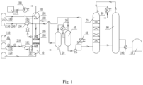
Fig. 1 is a structural diagram of a reaction system for preparing butyraldehyde by propylene carbonylation according to an embodiment of the present invention; -
Fig. 2 is a structure diagram of a sprayer according to an embodiment of the present invention; and -
Fig. 3 is a structure diagram of a bubble generator according to an embodiment of the present invention. -
10 reactor; 101 synthesis gas inlet; 102 propene inlet; 103 catalyst inlet; 104 sprayer; 105 micro-interface generator; 106 gas distributor; 1061 distributor body; 1062 nozzle; 107 solvent inlet; 108 product outlet; 20 demister; 30 second condenser; 40 gas-liquid separator; 50 circulation pump; 60 third condenser; 70 isomer separation tower; 80 fourth condenser; 90 rectification tower; 100 reboiler; 110 n-butyraldehyde storage tank; 120 solvent storage tank; 130 carbon monoxide storage tank; 140 hydrogen storage tank; 150 propylene storage tank; 160 catalyst storage tank; 170 combustion system 180 first condenser; 190 bubble generator; 1901 gas-phase main channel; 1902 liquid-phase branch channel; 200 propylene pipeline; 201 synthesis gas pipeline. - The technical schemes of the present invention will be clearly and completely described below in conjunction with the embodiments and the accompanying drawings. Those skilled in the art will understand that the following embodiments are some embodiments of the present invention, rather than all embodiments, and are only for illustrating the present invention, and should not be considered as limiting the scope of the present invention. Based on the embodiments of the present invention, all other embodiments obtained by persons of ordinary skill in the art without making creative efforts belong to the protection scope of the present invention. Those who do not indicate the specific conditions in the embodiments are carried or according to the conventional conditions or the conditions suggested by the manufacturer. The reagents or instruments used were not indicated by the manufacturer, and they were all conventional products that could be purchased from the market.
- In the description of the present invention, it should be noted that the terms for indicating the orientation or positional relationship, such as "center", "upper", "lower", "left", "right", "vertical", "horizontal", "inner", "outer" etc. is based on the orientation or positional relationship shown in the drawings, and is only for the convenience of describing the present invention and simplifying the description; it is not intended to indicate or imply that the referred device or element must have a particular orientation, be constructed in a particular orientation, and operate in a particular orientation, and thus should be not construed as limiting the invention. In addition, the terms "first", "second", and "third" are used for descriptive purposed only, which should be not construed as indicating or implying relative importance.
- In the description of the present invention, it should be noted that unless otherwise specified and limited, the terms "installed", "connection", "coupling" should be understood in a broad sense. For example, it can be a fixed connection, a detachable connection, or an integral connection; it can be a mechanical connection or an electrical connection; it can be a direct connection or an indirect connection through an intermediary, and it can be the internal connection between two components. Those of ordinary skill in the art can understand the specific meanings of the above items in the present invention in specific situations.
- In order to illustrate the technical schemes in the present invention more clearly, the following will be described in the form of specific embodiments.
- Referring to
Fig. 1 to Fig. 3 , a reaction system for preparing butyraldehyde by propylene carbonylation is provided in this embodiment, which includes: areactor 10, apropylene storage tank 150, a carbonmonoxide storage tank 130, ahydrogen storage tank 140, apropylene pipeline 200 and asynthesis gas pipeline 210. The side wall of thereactor 10 is provided with apropylene inlet 102 and asynthesis gas inlet 101 sequentially from top to bottom. - The
propylene inlet 102 is connected to thepropylene storage tank 150 through thepropylene pipeline 200; the carbonmonoxide storage tank 130 is connected in parallel with thehydrogen storage tank 140, and both of them are connected to thesynthesis gas inlet 101 through thesynthesis gas pipeline 210. Both thepropylene pipeline 200 and thesynthesis gas pipeline 210 are provided with abubble generator 190 for pre-dispersing and breaking the gas into bubbles. - As shown in
Fig. 3 , thebubble generator 190 includes a gas-phasemain channel 1901 and a liquid-phase branch channel 1902; the liquid-phase branch channel 1902 is connected with thereactor 10, and the solvent in thereactor 10 enters the gas-phasemain channel 1901 through the liquid-phase branch channel and mixes with the gas in the gas-phasemain channel 1901 to form bubbles. - During the reaction, propylene enters the gas-phase
main channel 1901 of thebubble generator 190 through thepropylene pipeline 200, and the solvent in thereactor 10 enters the gas-phasemain channel 1901 through the liquid-phase branch channel 1902, and mixes with the propylene in the gas-phasemain channel 1901 to form propylene bubbles, the propylene bubbles and the remaining solvent flow back into thereactor 10 from thepropylene inlet 102. At the same time, the synthesis gas enters the gas-phasemain channel 1901 of thebubble generator 190 through thesynthesis gas pipeline 210, and the solvent in thereactor 10 enters the gas-phasemain channel 1901 through the liquid-phase branch channel 1902, and mixes with he synthesis gas in the gas-phasemain channel 1901 to form synthesis gas bubbles, propylene bubbles and the remaining solvent flow back into thereactor 10 form thepropylene inlet 102. A water pump is arranged at the inlet of the liquid-phase branch channel 1902 to pump the solvent to the liquid-phase branch channel 1902. - The interior of the
reactor 10 is provided with twomicro-interface generators 105 from top to bottom. Themicro-interface generator 105 at the top is connected to thepropylene inlet 102 to break the propylene gas into micron-scale micro-bubbles; and themicro-interface generator 105 at the bottom is connected to thesynthesis gas inlet 101 for breaking the synthesis gas into micron-scale micro-bubbles. The outlets of the twomicro-interface generators 105 are opposite, and both of the outlets are connected withgas distributors 106 for evenly distributing raw materials. - As shown in
Fig. 2 , thegas distributor 106 includes adistributor body 1061 and a plurality ofnozzles 1062; the plurality ofnozzles 1062 are obliquely arranged on thedistributor body 1061 to uniformly disperse the micro-bubbles generated by themicro-interface generator 105. - A
catalyst inlet 103 is arranged on the side wall of thereactor 10, and asprayer 104 is also arranged in thereactor 10, wherein thesprayer 104 is located above themicro-interface generator 105. Thesprayer 104 is connected with thecatalyst inlet 103; and thecatalyst inlet 103 is connected with acatalyst storage tank 160. During the reaction, the catalyst is sprayed by thesprayer 104 to make the catalyst distribution more uniform. The catalyst used in this embodiment is a rhodium catalyst. - A
first condenser 180 is connected to the top of thereactor 10; a non-condensable gas outlet of thefirst condenser 180 is connected to thecombustion system 170; and a condensate outlet of thefirst condenser 180 is connected to thereactor 10. The tail gas at the top of thereactor 10 is condensed by thefirst condenser 180, high boiling point substances such as n-butyraldehyde/ Isobutyraldehyde are condensed into liquids and returned to thereactor 10, and non-condensable gases such as nitrogen, hydrogen, propane, and carbon monoxide enter thecombustion system 170 for combustion remove. - A
solvent inlet 107 is arranged at the bottom of thereactor 10, and thesolvent inlet 107 is connected to asolvent storage tank 120. The solvent in thesolvent storage tank 120 flows into thereactor 10 through thesolvent inlet 107 to provide a medium for the reaction. In this embodiment, the selected solvent is n-butyraldehyde or Isobutyraldehyde. - In this embodiment, the
reactor 10 is provided with aproduct outlet 108, and theproduct outlet 108 is connected with ademister 20. Thedemister 20 is connected with a gas-liquid separator 40, anisomer separation tower 70 and arectification tower 90 in sequence. Therectification tower 90 is connected with a n-butyraldehyde storage tank 110. Thedemister 20 captures the small liquid droplets entrained in the gas flow from thereactor 10 and returns them to thereactor 10. - A
fourth condenser 80 is arranged at the top of theisomer separation tower 70. Since the difference between the boiling points of n-butanol and isobutanol is small, a plurality of trays is arranged in theisomer separation tower 70 to increase the reflux. - Specifically, a
second condenser 30 is provided between thedemister 20 and the gas-liquid separator 40. The product demisted by thedemister 20 is condensed by thesecond condenser 30 and flows into the gas-liquid separator 40. Thesecond condenser 30 condenses the product in the gas-phase and flows into the gas-liquid separator 40. - In addition, the gas-
liquid separator 40 is also connected with athird condenser 60, and thethird condenser 60 is connected with themicro-interface generator 105 located at the top of thereactor 10. A part of the product separated by the gas-liquid separator 40 flows directly into theisomer separation tower 70, and another part of the product flows back into thereactor 10 after being condensed by thethird condenser 60. Further, the outlet of the gas-liquid separator 40 is provided with a circulation pump 50, and the liquid-phase flow at the bottom of the gas-liquid separator 40 enters the circulation pump 50 to increase the pressure. A part of the material at the outlet of the circulation pump 50 flows into theisomer separation tower 70 as a crude product, and the other part is cooled by thethird condenser 60 to about 80°C and returned to themicro-interface generator 105 in thereactor 10 to continue to participate in the reaction. - The outlet of the
rectification tower 90 is provided with areboiler 100, and thereboiler 100 divides the stream flowing out from therectification tower 90 into a gas-phase stream and a liquid-phase stream, wherein the gas-phase stream flows back to therectification tower 90, and the liquid-phase stream flows into the n-butyraldehyde storage tank 110. - The specific reaction process of the reaction system of this embodiment is as follows:
Before the reaction, thereactor 10 is filled with a solvent, and the twomicro-interface generators 105 are immersed in the solvent. During the reaction, propylene enters thebubble generator 190 through thepropylene pipeline 200, disperses and breaks into large propylene bubbles under the participation of the solvent, and enters themicro-interface generator 105 through thepropylene inlet 103, and the bubbles are further dispersed and broken into micron-scale micro-bubbles in themicro-interface generator 105. At the same time, carbon monoxide and hydrogen are mixed in thesynthesis gas pipeline 210 for form the synthesis gas. The synthesis gas enters thebubble generator 190 through thesynthesis gas pipeline 210, and it is dispersed and broken into large synthesis gas bubbles under the participation of the solvent. The large synthesis gas bubbles enter into themicro-interface generator 105 through thesynthesis gas inlet 101, and then the large synthesis gas bubbles are further dispersed and broken into micron-scale micro-bubbles in themicro-interface generator 105. The catalyst is evenly sprayed into the solvent through thesprayer 104, and the generated micro-bubbles undergo carbonylation reaction in the solvent. The reaction product is defoamed by thedemister 20 and then condensed by thesecond condenser 30 and flows into the gas-liquid separator 40. The gas-phase after the gas-liquid separation flows back into thereactor 10, a part of the liquid-phase enters theisomer separation tower 70, and the other part of the liquid-phase is cooled by thethird condenser 60 to about 80°C and returned to themicro-interface generator 105 in thereactor 10 to continue to participate in the reaction. Theisomer separation tower 70 separates the products, and the separated n-butyraldehyde flows into the n-butyraldehyde storage tank 110 after being rectified in therectification tower 90. - In a word, compared with the reaction system for preparing butyraldehyde by propylene carbonylation in the prior art, the reaction system of the present invention has low energy consumption, low cost, high safety, lower required reaction temperature and low reaction pressure, few side reactions, and high yield of n-butyraldehyde, so it is worthy of wide popularization and application.
- Finally, it can be understood that the above Embodiments are merely exemplary implementations adopted to illustrate the principle of the present invention, but the present invention is not limited thereto. Although the present invention has been described in detail with reference to the foregoing embodiments, those skilled in the art should understand that: it can still modify the technical schemes described in the foregoing embodiments or perform equivalent replacements for some or all of the technical features. However, without departing from the principle and essence of the present invention, various modifications and improvements can be made, and these modifications and improvements are also regarded as the protection scope of the present invention.
Claims (10)
- A reaction system for preparing butyraldehyde by propylene carbonylation, characterized in that, comprising:a reactor, a propylene storage tank, a carbon monoxide storage tank, a hydrogen storage tank, a propylene pipeline and a synthesis gas pipeline; a side wall of the reactor is sequentially provided with a propylene inlet and a synthesis gas inlet from top to bottom;two micro-interface generators are arranged inside the reactor from top to bottom, and the micro-interface generator located at a top is connected with the propylene inlet to break the propylene gas into micron-scale micro-bubbles; the micro-interface generator located at a bottom is connected with the synthesis gas inlet for breaking the synthesis gas into micron-scale micro-bubbles; outlets of the two micro-interface generators are opposite, and the outlets are connected with a gas distributor for evenly distributing raw materials;the propylene inlet is connected to the propylene storage tank through the propylene pipeline, the carbon monoxide storage tank is connected in parallel with the hydrogen storage tank, and both the carbon monoxide storage tank and the hydrogen storage tank are connected to the synthesis gas inlet through the synthesis gas pipeline; both the propylene pipeline and the synthesis gas pipeline are provided with bubble generators for pre-dispersing and breaking the gas into bubbles.
- The reaction system for preparing butyraldehyde by propylene carbonylation according to claim 1, wherein the gas distributor comprises a distributor body and a plurality of nozzles; the plurality of nozzles is obliquely arranged on the distributor body for uniformly dispersing the micro-bubbles generated by the micro-interface generators.
- The reaction system for preparing butyraldehyde by propylene carbonylation according to claim 1, wherein the bubble generator comprises a gas-phase main channel and a liquid-phase branch channel; the liquid-phase branch channel is connected to the reactor, and a solvent in the reactor enters the gas-phase main channel through the gas-phase branch channel through the liquid-phase branch channel for mixing with the gas in the gas-phase main channel to form bubbles.
- The reaction system for preparing butyraldehyde by propylene carbonylation according to claim 1, wherein a catalyst inlet is arranged on the side wall of the reactor, and a sprayer is arranged in the reactor and the sprayer is located at a top of the micro-interface generator; the sprayer is connected to the catalyst inlet; and the catalyst inlet is connected with a catalyst storage tank.
- The reaction system for preparing butyraldehyde by propylene carbonylation according to claim 1, wherein the top of the reactor is connected with a first condenser; a non-condensable gas outlet of the first condenser is connected with a combustion system, and a condensate outlet of the first condenser is connected with the reactor.
- The reaction system for preparing butyraldehyde by propylene carbonylation according to claim 1, wherein a solvent inlet is arranged at the bottom of the reactor, and the solvent inlet is connected with a solvent storage tank.
- The reaction system for preparing butyraldehyde by propylene carbonylation according to claim 1, wherein the reactor is provided with a product outlet, and the product outlet is connected with a demister; the demister is sequentially connected with a gas-liquid separator, an isomer separation tower and a rectification tower, and the rectification tower is connected with an n-butyraldehyde storage tank; a second condenser is arranged between the demister and the gas-liquid separator; the product defoamed by the demister is condensed and flows into the demister through the second condenser in the gas-liquid separator.
- The reaction system for preparing butyraldehyde by propylene carbonylation according to claim 7, wherein the gas-liquid separator is connected with a third condenser, and the third condenser is connected with the micro-interface generator located at the top of the reactor; one part of the product separated by the gas-liquid separator directly flows into the isomer separation tower, and another part of the product flows back into the reactor after being condensed by the third condenser.
- A reaction method using the reaction system for preparing butyraldehyde by propylene carbonylation according to any one of claims 1-8, comprising the following steps:
after dispersing and crushing the propylene and the synthesis gas through the micro-interface generators, they are mixed with catalysts to carry out a hydroxyl synthesis reaction; and then a crude product is obtained after defoaming and condensing gas-liquid separation, a separation is performed on the crude product, such that n-butyraldehyde is separated from isobutyraldehyde, and n-butyraldehyde is obtained after rectification and purification. - The reaction method according to claim 9, wherein a reaction temperature of a hydroxyl synthesis is 85-90°C, and a reaction pressure is 1.1-1.8Mpa; the catalyst is a rhodium catalyst.
Applications Claiming Priority (2)
| Application Number | Priority Date | Filing Date | Title |
|---|---|---|---|
| CN202110354339.1A CN113041962B (en) | 2021-04-01 | 2021-04-01 | Reaction system and method for preparing butyraldehyde by propylene carbonylation |
| PCT/CN2021/109748 WO2022205717A1 (en) | 2021-04-01 | 2021-07-30 | Reaction system and method for preparing butyraldehyde by propylene carbonylation |
Publications (1)
| Publication Number | Publication Date |
|---|---|
| EP4316642A1 true EP4316642A1 (en) | 2024-02-07 |
Family
ID=76517098
Family Applications (1)
| Application Number | Title | Priority Date | Filing Date |
|---|---|---|---|
| EP21934361.3A Pending EP4316642A1 (en) | 2021-04-01 | 2021-07-30 | Reaction system and method for preparing butyraldehyde by propylene carbonylation |
Country Status (4)
| Country | Link |
|---|---|
| US (1) | US11919845B2 (en) |
| EP (1) | EP4316642A1 (en) |
| CN (1) | CN113041962B (en) |
| WO (1) | WO2022205717A1 (en) |
Families Citing this family (3)
| Publication number | Priority date | Publication date | Assignee | Title |
|---|---|---|---|---|
| CN113041962B (en) * | 2021-04-01 | 2023-05-26 | 南京延长反应技术研究院有限公司 | Reaction system and method for preparing butyraldehyde by propylene carbonylation |
| CN113683545B (en) * | 2021-08-31 | 2023-06-27 | 南京延长反应技术研究院有限公司 | System and method for preparing cyclohexyl hydroperoxide by oxidizing cyclohexane |
| CN113971988B (en) | 2021-11-08 | 2023-05-05 | 南京延长反应技术研究院有限公司 | Evaluation method for reaction enhancement degree of micro-interface for preparing butyraldehyde by propylene hydroformylation |
Family Cites Families (25)
| Publication number | Priority date | Publication date | Assignee | Title |
|---|---|---|---|---|
| DE2749890B2 (en) * | 1977-11-08 | 1980-05-08 | Chemische Werke Huels Ag, 4370 Marl | Process for the recovery of propene or propene-propane mixtures from the exhaust gases of the hydroformylation of propene |
| DE10006489A1 (en) * | 2000-02-14 | 2001-08-16 | Basf Ag | Process for working up a liquid hydroformylation discharge |
| WO2012008717A2 (en) * | 2010-07-14 | 2012-01-19 | Lg Chem, Ltd. | Apparatus for coproducting iso type reaction products and alcohols from olefins, and method for coproducting them using the apparatus |
| CN105903425B (en) | 2016-04-21 | 2018-09-07 | 南京大学 | Injection reactor |
| CN205833127U (en) | 2016-05-11 | 2016-12-28 | 南京大学 | A kind of ultra high efficiency oxidation reaction apparatus being prepared Ketohexamethylene by hexamethylene |
| CN106187660B (en) | 2016-09-08 | 2018-11-20 | 南京大学 | The device and technique of producing cyclohexane by adding hydrogen in benzene |
| CN207581700U (en) | 2017-06-19 | 2018-07-06 | 南京大学 | A kind of liquid phase chlorination method process units of four chloro- 2- cyanopyridines |
| CN109437390A (en) | 2018-12-19 | 2019-03-08 | 南京大学盐城环保技术与工程研究院 | A kind of reactor and its application method of catalytic ozonation waste water |
| CN111482141A (en) * | 2019-01-29 | 2020-08-04 | 南京延长反应技术研究院有限公司 | Bottom-mounted residual oil hydrogenation fluidized bed micro-interface enhanced reaction device and method |
| CN111495288A (en) * | 2019-01-30 | 2020-08-07 | 南京大学 | Up-down opposite-impact type micro-interface enhanced reaction device and method |
| CN111646883A (en) * | 2019-03-04 | 2020-09-11 | 内蒙古伊泰煤基新材料研究院有限公司 | Method for preparing aldehyde by hydroformylation of low-carbon olefin |
| CN112479840A (en) * | 2019-09-12 | 2021-03-12 | 南京延长反应技术研究院有限公司 | Intelligent control reaction system and process for preparing butanol and octanol through propylene carbonylation |
| CN112479815A (en) * | 2019-09-12 | 2021-03-12 | 南京延长反应技术研究院有限公司 | Reaction system and process for preparing butanol and octanol through propylene carbonylation based on micro-interface reinforcement |
| CN111302917B (en) * | 2020-03-27 | 2022-10-14 | 中国海洋石油集团有限公司 | Olefin hydroformylation device and method |
| CN112010735A (en) * | 2020-08-18 | 2020-12-01 | 南京延长反应技术研究院有限公司 | External micro-interface strengthening system and method for preparing butanol and octanol through propylene carbonylation |
| CN112403006A (en) * | 2020-11-20 | 2021-02-26 | 南京延长反应技术研究院有限公司 | Enhanced micro-interface reaction system and method for preparing formic acid by carbon dioxide hydrogenation |
| CN112479852A (en) * | 2020-11-20 | 2021-03-12 | 南京延长反应技术研究院有限公司 | Preparation system and method of formic acid |
| CN112441878A (en) * | 2020-11-30 | 2021-03-05 | 南京延长反应技术研究院有限公司 | Intelligent reaction system and method for preparing ethylene glycol by gas-phase catalytic hydration method |
| CN112521250A (en) * | 2020-11-30 | 2021-03-19 | 南京延长反应技术研究院有限公司 | Micro-interface reaction system and method for preparing ethylene glycol by gas-phase catalytic hydration method |
| CN112457169A (en) * | 2020-11-30 | 2021-03-09 | 南京延长反应技术研究院有限公司 | Reaction system and method for preparing ethylene glycol by oxalate method |
| CN112452268A (en) * | 2020-12-03 | 2021-03-09 | 南京延长反应技术研究院有限公司 | Micro-interface reaction system and method for preparing ethylene glycol by oxalate method |
| CN113058517B (en) * | 2021-03-23 | 2023-05-05 | 南京延长反应技术研究院有限公司 | Micro-interface preparation device and method for butanol and octanol |
| CN113045387A (en) * | 2021-03-23 | 2021-06-29 | 南京延长反应技术研究院有限公司 | Reaction system and method for preparing butanol and octanol through propylene carbonylation |
| CN113019291A (en) * | 2021-03-23 | 2021-06-25 | 南京延长反应技术研究院有限公司 | Octanol production system and method |
| CN113041962B (en) * | 2021-04-01 | 2023-05-26 | 南京延长反应技术研究院有限公司 | Reaction system and method for preparing butyraldehyde by propylene carbonylation |
-
2021
- 2021-04-01 CN CN202110354339.1A patent/CN113041962B/en active Active
- 2021-07-30 WO PCT/CN2021/109748 patent/WO2022205717A1/en active Application Filing
- 2021-07-30 EP EP21934361.3A patent/EP4316642A1/en active Pending
- 2021-07-30 US US18/276,252 patent/US11919845B2/en active Active
Also Published As
| Publication number | Publication date |
|---|---|
| CN113041962A (en) | 2021-06-29 |
| CN113041962B (en) | 2023-05-26 |
| US20240034707A1 (en) | 2024-02-01 |
| US11919845B2 (en) | 2024-03-05 |
| WO2022205717A1 (en) | 2022-10-06 |
Similar Documents
| Publication | Publication Date | Title |
|---|---|---|
| EP4316642A1 (en) | Reaction system and method for preparing butyraldehyde by propylene carbonylation | |
| CN113061080A (en) | Micro-interface reaction system and method for preparing butyraldehyde by propylene carbonylation | |
| WO2022198873A1 (en) | Octanol production system and method | |
| CN113061081A (en) | Micro-interface enhanced reaction system and method for preparing butyraldehyde by propylene carbonylation | |
| CN113045387A (en) | Reaction system and method for preparing butanol and octanol through propylene carbonylation | |
| CN113058517B (en) | Micro-interface preparation device and method for butanol and octanol | |
| CN112321409A (en) | Reaction system and method for preparing formic acid by carbon dioxide hydrogenation | |
| CN109847658B (en) | Slurry bed reactor and reaction method | |
| WO2022105300A1 (en) | Enhanced micro-interface reaction system and method for preparing formic acid by carbon dioxide hydrogenation | |
| CN112479852A (en) | Preparation system and method of formic acid | |
| CN111807926A (en) | Reaction system and method for preparing ethanol from coal | |
| CN111848344A (en) | Reaction system and method for preparing ethanol by adopting synthesis gas | |
| WO2022110871A1 (en) | Enhanced micro-interface reaction system and method for preparing ethylene glycol by oxalate method | |
| WO2023284031A1 (en) | Built-in instant dehydration micro-interface enhanced dmc preparation system and method | |
| CN100420731C (en) | Coal hydrogenation reaction device and its industrial application | |
| CN113072438A (en) | Intelligent micro-interface reaction system and method for preparing butyraldehyde by propylene carbonylation | |
| CN113546589A (en) | System and method for preparing DMC (dimethyl formamide) through micro-interface reinforcement | |
| CN112028768A (en) | Reaction system and method for preparing glycolate through oxalate hydrogenation | |
| CN112409158A (en) | Enhanced micro-interface preparation system and method for formic acid | |
| WO2023284024A1 (en) | Micro-interface strengthening system for preparing octenal by n-butyraldehyde condensation, and preparation method | |
| CN214598924U (en) | Micro-interface preparation device of butanol and octanol | |
| CN216024809U (en) | 2-methyl tetrahydrofuran's micro-interface preparation system | |
| CN113680286B (en) | Propylene carbonylation reaction system and method with recyclable catalyst | |
| CN216024781U (en) | N-butyraldehyde condensation reaction system based on micro-interface | |
| CN216778779U (en) | Micro-interface preparation system of trimellitic acid |
Legal Events
| Date | Code | Title | Description |
|---|---|---|---|
| STAA | Information on the status of an ep patent application or granted ep patent |
Free format text: STATUS: THE INTERNATIONAL PUBLICATION HAS BEEN MADE |
|
| PUAI | Public reference made under article 153(3) epc to a published international application that has entered the european phase |
Free format text: ORIGINAL CODE: 0009012 |
|
| STAA | Information on the status of an ep patent application or granted ep patent |
Free format text: STATUS: REQUEST FOR EXAMINATION WAS MADE |
|
| 17P | Request for examination filed |
Effective date: 20230928 |
|
| AK | Designated contracting states |
Kind code of ref document: A1 Designated state(s): AL AT BE BG CH CY CZ DE DK EE ES FI FR GB GR HR HU IE IS IT LI LT LU LV MC MK MT NL NO PL PT RO RS SE SI SK SM TR |