EP4316327A1 - Staubsauger mit verbesserter auslösung der kabelaufwicklung - Google Patents
Staubsauger mit verbesserter auslösung der kabelaufwicklung Download PDFInfo
- Publication number
- EP4316327A1 EP4316327A1 EP23184912.6A EP23184912A EP4316327A1 EP 4316327 A1 EP4316327 A1 EP 4316327A1 EP 23184912 A EP23184912 A EP 23184912A EP 4316327 A1 EP4316327 A1 EP 4316327A1
- Authority
- EP
- European Patent Office
- Prior art keywords
- vacuum cleaner
- cable
- sensor
- touching
- retraction
- Prior art date
- Legal status (The legal status is an assumption and is not a legal conclusion. Google has not performed a legal analysis and makes no representation as to the accuracy of the status listed.)
- Granted
Links
Images
Classifications
-
- A—HUMAN NECESSITIES
- A47—FURNITURE; DOMESTIC ARTICLES OR APPLIANCES; COFFEE MILLS; SPICE MILLS; SUCTION CLEANERS IN GENERAL
- A47L—DOMESTIC WASHING OR CLEANING; SUCTION CLEANERS IN GENERAL
- A47L9/00—Details or accessories of suction cleaners, e.g. mechanical means for controlling the suction or for effecting pulsating action; Storing devices specially adapted to suction cleaners or parts thereof; Carrying-vehicles specially adapted for suction cleaners
- A47L9/28—Installation of the electric equipment, e.g. adaptation or attachment to the suction cleaner; Controlling suction cleaners by electric means
- A47L9/2857—User input or output elements for control, e.g. buttons, switches or displays
-
- A—HUMAN NECESSITIES
- A47—FURNITURE; DOMESTIC ARTICLES OR APPLIANCES; COFFEE MILLS; SPICE MILLS; SUCTION CLEANERS IN GENERAL
- A47L—DOMESTIC WASHING OR CLEANING; SUCTION CLEANERS IN GENERAL
- A47L9/00—Details or accessories of suction cleaners, e.g. mechanical means for controlling the suction or for effecting pulsating action; Storing devices specially adapted to suction cleaners or parts thereof; Carrying-vehicles specially adapted for suction cleaners
- A47L9/26—Incorporation of winding devices for electric cables
-
- B—PERFORMING OPERATIONS; TRANSPORTING
- B65—CONVEYING; PACKING; STORING; HANDLING THIN OR FILAMENTARY MATERIAL
- B65H—HANDLING THIN OR FILAMENTARY MATERIAL, e.g. SHEETS, WEBS, CABLES
- B65H75/00—Storing webs, tapes, or filamentary material, e.g. on reels
- B65H75/02—Cores, formers, supports, or holders for coiled, wound, or folded material, e.g. reels, spindles, bobbins, cop tubes, cans, mandrels or chucks
- B65H75/34—Cores, formers, supports, or holders for coiled, wound, or folded material, e.g. reels, spindles, bobbins, cop tubes, cans, mandrels or chucks specially adapted or mounted for storing and repeatedly paying-out and re-storing lengths of material provided for particular purposes, e.g. anchored hoses, power cables
- B65H75/38—Cores, formers, supports, or holders for coiled, wound, or folded material, e.g. reels, spindles, bobbins, cop tubes, cans, mandrels or chucks specially adapted or mounted for storing and repeatedly paying-out and re-storing lengths of material provided for particular purposes, e.g. anchored hoses, power cables involving the use of a core or former internal to, and supporting, a stored package of material
- B65H75/40—Cores, formers, supports, or holders for coiled, wound, or folded material, e.g. reels, spindles, bobbins, cop tubes, cans, mandrels or chucks specially adapted or mounted for storing and repeatedly paying-out and re-storing lengths of material provided for particular purposes, e.g. anchored hoses, power cables involving the use of a core or former internal to, and supporting, a stored package of material mobile or transportable
- B65H75/42—Cores, formers, supports, or holders for coiled, wound, or folded material, e.g. reels, spindles, bobbins, cop tubes, cans, mandrels or chucks specially adapted or mounted for storing and repeatedly paying-out and re-storing lengths of material provided for particular purposes, e.g. anchored hoses, power cables involving the use of a core or former internal to, and supporting, a stored package of material mobile or transportable attached to, or forming part of, mobile tools, machines or vehicles
-
- B—PERFORMING OPERATIONS; TRANSPORTING
- B65—CONVEYING; PACKING; STORING; HANDLING THIN OR FILAMENTARY MATERIAL
- B65H—HANDLING THIN OR FILAMENTARY MATERIAL, e.g. SHEETS, WEBS, CABLES
- B65H75/00—Storing webs, tapes, or filamentary material, e.g. on reels
- B65H75/02—Cores, formers, supports, or holders for coiled, wound, or folded material, e.g. reels, spindles, bobbins, cop tubes, cans, mandrels or chucks
- B65H75/34—Cores, formers, supports, or holders for coiled, wound, or folded material, e.g. reels, spindles, bobbins, cop tubes, cans, mandrels or chucks specially adapted or mounted for storing and repeatedly paying-out and re-storing lengths of material provided for particular purposes, e.g. anchored hoses, power cables
- B65H75/38—Cores, formers, supports, or holders for coiled, wound, or folded material, e.g. reels, spindles, bobbins, cop tubes, cans, mandrels or chucks specially adapted or mounted for storing and repeatedly paying-out and re-storing lengths of material provided for particular purposes, e.g. anchored hoses, power cables involving the use of a core or former internal to, and supporting, a stored package of material
- B65H75/44—Constructional details
- B65H75/4481—Arrangements or adaptations for driving the reel or the material
- B65H75/4484—Electronic arrangements or adaptations for controlling the winding or unwinding process, e.g. with sensors
-
- B—PERFORMING OPERATIONS; TRANSPORTING
- B65—CONVEYING; PACKING; STORING; HANDLING THIN OR FILAMENTARY MATERIAL
- B65H—HANDLING THIN OR FILAMENTARY MATERIAL, e.g. SHEETS, WEBS, CABLES
- B65H2701/00—Handled material; Storage means
- B65H2701/30—Handled filamentary material
- B65H2701/34—Handled filamentary material electric cords or electric power cables
Definitions
- the mains cable (colloquially known as cable) is usually wound up after use using a spring-loaded cable drum.
- the trigger mechanism for winding up is usually triggered by pressing a switching element on the vacuum cleaner (the so-called kick button). In some cases it is only rolled up for as long as the foot button is pressed, in other cases the entire power cable is completely wound up after pressing the foot button once (a so-called comfort retraction).
- the invention therefore faces the problem of improving cable winding.
- the user can trigger the winding process immediately after unplugging the power plug from the socket, without having to return to the vacuum first. He no longer has to press the step button, which is usually not within reach at the moment the power plug is unplugged. The user can - without touching the plug contacts - easily insert the plug from one socket into the next without triggering the winding process.
- the cable receptacle has a spring mechanism which is tensioned by pulling out the connecting cable in order to cause the connecting cable to be retracted, and a locking device which blocks the spring mechanism when the connecting cable is pulled out, the triggering device comprising an electrical actuator which is used for Releasing the locking device is set up to trigger retraction.
- a single touch triggers complete retraction.
- the triggered retraction is canceled by further touching.
- the retraction is carried out only during touching.
- the user can optionally interrupt winding again by touching the plug contacts again.
- the winding process can also be designed in such a way that it only continues as long as the plug contacts are touched.
- the senor is a resistive sensor that is designed to detect simultaneous touching of at least two poles of the power plug as touching.
- Touching the power plug can be detected, for example, by a high-resistance impedance measurement between the two plug pins.
- the connector pins must be touched or bridged at the same time.
- a finger contact resistance between preferably 2 kOhm and 10 kOhm should be detected using an applied measuring voltage/low voltage and, if detected accordingly, lead to one of the actions described above.
- the senor is a capacitive sensor.
- the capacitive change that occurs when the contacts of the power plug are touched by a user's fingers/hand is measured.
- the particular advantage is that just touching one connector pin is sufficient for evaluation and the connector pins no longer have to be touched or bridged at the same time.
- the household appliance further comprises a mechanical button for releasing the locking device.
- Triggering by touch can also take place because the actuator can release the locking device parallel to the pedal button.
- the household appliance includes a sensor button for manual actuation of the actuator.
- the mechanical kick button can be completely eliminated and the locking device can only be controlled by the electrical actuator.
- An optional sensor field is possible instead of a foot button. With this option, new designs and shapes of the household appliance can be realized.
- the invention can be used in any non-stationary household appliance with a power cord; it is preferably used in a vacuum cleaner.
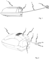
- FIG. 1 is a wired vacuum cleaner 1 shown as an example of an electrical household appliance (suction tube, floor nozzle, etc. not shown here) in which the present invention can be used.
- the assumption here is a vacuum cleaner 1 with a (preferably) internal cable holder 2 (indicated here by dashed lines) for a power cable 2, in which the power cable 3 can be stored internally in the vacuum cleaner 1 when retracted.
- the cable holder 2 is equipped with an automatic cable retraction, for example in the form of a cable drum, in which a spring is tensioned when the cable is pulled out, which is mechanically blocked by a locking device when pulled out, so that the power cable is not immediately retracted.
- This spring tension can in turn be used by removing the blocking, for example using a foot switch, to cause the power cable 3 to be retracted.
- the power cord 3 can be pulled out and connected to a household socket 4.
- the vacuum cleaner 1 can thus be supplied with power and suction operations can be carried out with it.
- the extended power cable 3 should be regularly pulled back into the internal cable holder 2 in order to store the vacuum cleaner in a cupboard, for example.
- the present invention provides an alternative solution to triggering the known cable retraction.
- FIG 2 an embodiment of a vacuum cleaner 1 is shown, with all the elements as already in Figure 1 described, but here with the power cable 3 partially retracted.
- the power cable 3 has a power plug 5 with two poles or plug contacts 6a and 6b.
- the vacuum cleaner 1 has a triggering device 7 (which can, for example, be part of a control unit of the vacuum cleaner, symbolized here by the rotary controller), which uses a sensor (not shown) to detect touching of at least one pole 6a and / or 6b of the power plug by a user can capture. If such a touch is detected, the triggering device 7 triggers the power cable 3 to be pulled in.
- a triggering device 7 which can, for example, be part of a control unit of the vacuum cleaner, symbolized here by the rotary controller, which uses a sensor (not shown) to detect touching of at least one pole 6a and / or 6b of the power plug by a user can capture. If such a touch is detected, the triggering device 7 triggers the power cable 3 to be pulled in.
- an additional actuator in the form of an electromagnet which acts on the locking device.
- the actuator In the de-energized state, the actuator is only in contact with the locking device.
- the actuator is preferably powered by a supercapacitor or an accumulator in order to provide sufficient energy for actuation after the power cable has been disconnected.
- the same energy source can also be used to ensure potential-free measurement via the plug contacts.
- a kick button 8 is available to trigger the power cord 3 to be pulled into the cable receptacle 2 by a user on the vacuum cleaner 1 itself.
- the pedal button 8 can act purely mechanically on the cable receptacle 2 or its locking device; alternatively, the pedal button can also be designed as a pure sensor button that acts on an electrical actuator as described above.
- a touch can be measured in a resistive manner, in which case both plug contacts 6a and 6b must be touched.
- the contact can also be capacitive, which advantageously allows only one of the plug contacts 6a or 6b to be touched.
- a further electrically conductive contact is made on a surface of the vacuum cleaner, for example in the surface of the Step button, parallel triggering of the cable retraction is possible by touching these surfaces.
- Cheap microcontrollers (MC) with capacitive measurement inputs (touch read input) already provided in the hardware are suitable for use for this purpose. These microcontrollers are also recommended for their ability to provide advanced logic functions such as improved detection and sensing.
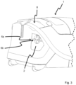
- FIG 3 shows another representation of the vacuum cleaner 1 Figure 2 , with the same elements, but here with the power cord fully retracted.
Landscapes
- Engineering & Computer Science (AREA)
- Mechanical Engineering (AREA)
- Details Of Connecting Devices For Male And Female Coupling (AREA)
- Electric Vacuum Cleaner (AREA)
Abstract
Description
- Bei kabelgebundenen Staubsaugern wird die Netzzuleitung (umgangssprachlich Kabel) üblicherweise nach Gebrauch mittels einer federgespannten Kabeltrommel aufgewickelt. Der Auslösemechanismus zum Aufwickeln wird in der Regel durch den Druck auf ein Schaltelement am Staubsauger (die sogenannte Tritttaste) ausgelöst. Teilweise wird nur so lange aufgerollt, wie die Tritttaste betätigt wird, teilweise wird die komplette Netzzuleitung nach einmaligem Betätigen der Tritttaste komplett aufgewickelt (ein sogenannter Komfort-Einzug).
- Üblich ist, dass der Benutzer nach Beendigung eines Saugvorganges zur Steckdose geht, dort den Netzstecker herauszieht und dann zum Staubsauger zurückkehrt - am besten mit dem Netzstecker in der Hand - um dort die Tritttaste zu betätigen und ggf. für die gesamte Dauer des Aufwickelvorganges gedrückt zu halten. Dabei muss der Benutzer gleichzeitig darauf achten, dass sich das Kabel nicht verknotet, so dass die Aufwicklung blockiert wird. Nimmt der Benutzer den Netzstecker nicht in die Hand mit zum Sauger, peitscht der Netzstecker während des Aufwickelvorganges mit erheblicher Energie durch die Wohnung. Dabei kann Mobiliar beschädigt oder Gegenstände umgeworfen werden, auch könnte der Benutzer oder eine andere Person durch den Netzstecker verletzt werden.
- Der Erfindung stellt sich somit das Problem, die Kabelaufwicklung zu verbessern.
- Erfindungsgemäß wird dieses Problem durch einen Staubsauger mit den Merkmalen des Patentanspruchs 1 gelöst. Vorteilhafte Ausgestaltungen und Weiterbildungen der Erfindung ergeben sich aus den nachfolgenden Unteransprüchen.
- Gemäß einem Aspekt der Erfindung wird ein Staubsauger bereitgestellt, umfassend:
- ein Anschlusskabel mit einem mindestens zweipoligen Netzstecker zur Verbindung des elektrischen Haushaltsgeräts mit einer Haushaltssteckdose;
- eine Kabelaufnahme, die zum Ausziehen und Einziehen des Anschlusskabels eingerichtet ist;
- einen Sensor, der dazu eingerichtet ist, ein Berühren von zumindest einem Pol des Netzsteckers durch einen Benutzer zu erfassen; und
- eine Auslöseeinrichtung, die dazu eingerichtet ist, in Reaktion auf das Berühren das Einziehen des ausgezogenen Anschlusskabels auszulösen.
- Der Benutzer kann mit dieser Lösung unmittelbar nach dem Ausstecken des Netzsteckers aus der Steckdose den Aufwickelvorgang auslösen, ohne zuvor zum Sauger zurückkehren zu müssen. Er muss den im Moment des Aussteckens des Netzsteckers in der Regel nicht direkt in Reichweite liegenden Tritttaster nicht mehr betätigen. Der Benutzer kann - ohne Berührung von Steckerkontakten - den Stecker ohne Weiteres von einer in die nächste Steckdose einstecken, ohne dabei den Aufwickelvorgang auszulösen.
- Gemäß einer Ausführungsform weist die Kabelaufnahme einen Federmechanismus auf, der durch Ausziehen des Anschlusskabels gespannt wird, um ein Einziehen des Anschlusskabels zu bewirken, sowie eine Sperrvorrichtung, die in ausgezogenem Zustand des Anschlusskabels den Federmechanismus blockiert, wobei die Auslöseeinrichtung einen elektrischen Aktor umfasst, der zum Freigeben der Sperrvorrichtung eingerichtet ist, um das Einziehen auszulösen.
- Gemäß einer Ausführungsform wird durch einmaliges Berühren ein vollständiges Einziehen ausgelöst.
- Gemäß einer Ausführungsform wird das ausgelöste Einziehen durch ein weiteres Berühren abgebrochen.
- Gemäß einer Ausführungsform wird das Einziehen nur während des Berührens ausgeführt.
- Der Benutzer kann optional das Aufwickeln durch erneute Berührung der Steckkontakte wieder unterbrechen. Alternativ kann der Aufwickelvorgang auch derart gestaltet werden, dass er sich nur so lange fortsetzt, wie die Steckkontakte berührt werden.
- Gemäß einer Ausführungsform ist der Sensor ein resistiver Sensor, der dazu eingerichtet ist, ein gleichzeitiges Berühren von zumindest zwei Polen des Netzsteckers als das Berühren zu erfassen.
- Die Berührung des Netzsteckers kann beispielsweise durch eine hochohmige Impedanzmessung zwischen den beiden Steckerstiften erfasst werden. Die Steckerstifte müssen gleichzeitig berührt bzw. überbrückt werden. Nach der Feststellung der Netzspannungsfreiheit soll mittels aufgelegter Messspannung/Kleinspannung ein Fingerkontaktwiderstand zwischen vorzugsweise 2 kOhm und 10 kOhm erfasst werden und bei entsprechender Detektion zu einer der oben beschriebenen Aktionen führen.
- Gemäß einer Ausführungsform ist der Sensor ein kapazitiver Sensor.
- In einer alternativen Ausführungsform wird anstelle einer Impedanzmessung über beide Steckerstifte die kapazitive Änderung gemessen, die bei einer Berührung der Kontakte des Netzsteckers durch die Finger/Hand eines Benutzers erfolgt. Der Vorteil liegt besonders darin, dass bereits die Berührung eines Steckerstiftes zur Auswertung hinreichend ist und die Steckerstifte nicht mehr gleichzeitig berührt bzw. überbrückt werden müssen.
- Gemäß einer Ausführungsform umfasst das Haushaltsgerät weiter eine mechanische Taste zum Freigeben der Sperrvorrichtung.
- Der Benutzer kann eine vorhandene Tritttaste (oder andere Auslösemöglichkeiten des Aufwickelvorgangs) nach wie vor benutzen. Die Auslösung durch Berührung kann zusätzlich erfolgen, da der Aktor die Sperrvorrichtung parallel zur Tritttaste lösen kann.
- Gemäß einer Ausführungsform umfasst das Haushaltsgerät eine Sensortaste zur manuellen Betätigung des Aktors.
- In einer solchen Ausführungsform kann die mechanische Tritttaste gänzlich entfallen und die Sperrvorrichtung nur noch durch den elektrischen Aktor gesteuert werden. Dabei ist ein optionales Sensorfeld anstatt einer Tritttaste möglich. Mit dieser Option lassen sich neue Designs und Formen des Haushaltsgeräts realisieren.
- Grundsätzlich kann die Erfindung bei jedem nicht-stationären Haushaltsgerät mit Netzkabel eingesetzt werden, bevorzugt wird sie bei einem Staubsauger eingesetzt.
- Ein Ausführungsbeispiel der Erfindung ist in den Zeichnungen rein schematisch dargestellt und wird nachfolgend näher beschrieben. Es zeigt
- Figur 1
- zeigt einen am Stromnetz angeschlossenen Staubsauger;
- Figur 2
- zeigt einen Staubsauger mit teilweise eingezogenem Netzkabel; und
- Figur 3
- zeigt einen Staubsauger mit vollständig eingezogenem Netzkabel.
- In
Figur 1 ist ein kabelgebundener Staubsauger 1 als Beispiel eines elektrischen Haushaltsgeräts gezeigt (Saugrohr, Bodendüse etc. hier nicht gezeigt), bei dem die vorliegende Erfindung eingesetzt werden kann. Es wird hier von einem Staubsauger 1 mit einer (vorzugweise) internen Kabelaufnahme 2 (hier gestrichelt angedeutet) für ein Netzkabel 2 ausgegangen, in welcher das Netzkabel 3 im eingezogenen Zustand intern im Staubsauger 1 aufbewahrt werden kann. Die Kabelaufnahme 2 ist mit einem automatischen Kabeleinzug ausgestattet, beispielsweise in Form einer Kabeltrommel, bei der durch Ausziehen des Kabels eine Feder gespannt wird, die im ausgezogenen Zustand mechanisch durch eine Sperrvorrichtung blockiert wird, so dass das Netzkabel nicht sofort wieder eingezogen wird. - Diese Federspannung kann wiederum durch Aufheben der Blockierung, beispielsweise mittels einer Fußtaste, genutzt werden, um ein Einziehen des Netzkabels 3 zu bewirken.
- Wie hier gezeigt, kann das Netzkabel 3 ausgezogen und mit einer Haushaltssteckdose 4 verbunden werden. Der Staubsauger 1 kann so mit Strom versorgt und Saugvorgänge damit ausgeführt werden.
- Nach einer Beendigung eines Saugvorgangs soll das ausgezogene Netzkabel 3 regelmäßig wieder in die interne Kabelaufnahme 2 eingezogen werden, um den Staubsauger beispielsweise in einem Schrank zu verstauen. Die vorliegende Erfindung stellt eine alternative Lösung bereit, den an sich bekannten Kabeleinzug auszulösen.
- In
Figur 2 ist eine Ausführungsform eines Staubsaugers 1 gezeigt, mit allen Elementen, wie bereits beiFigur 1 beschrieben, allerdings hier mit teilweise eingezogenem Netzkabel 3. Das Netzkabel 3 weist einen Netzstecker 5 mit zwei Polen bzw. Steckerkontakten 6a und 6b auf. - Der Staubsauger 1 weist eine Auslöseeinrichtung 7 auf (die beispielsweise Bestandteil einer Steuereinheit des Staubsaugers sein kann, hier durch den Drehregler symbolisiert), die mittels eines Sensors (nicht gezeigt) ein Berühren von zumindest einem Pol 6a und/oder 6b des Netzsteckers durch einen Benutzer erfassen kann. Wird eine solche Berührung erfasst, löst die Auslöseeinrichtung 7 das Einziehen des Netzkabels 3 aus.
- Gemäß einer Ausführungsform (nicht gezeigt) ist ein zusätzlicher Aktor in Form eines Elektromagneten vorhanden, der auf die Sperrvorrichtung wirkt. Im unbestromten Zustand liegt der Aktor nur an der Sperrvorrichtung an. Der Aktor wird vorzugsweise durch einen Superkondensator oder auch einen Akkumulator gespeist, um nach dem Trennen des Netzkabels hinreichend Energie zur Betätigung zur Verfügung zu stellen. Die gleiche Energiequelle kann auch benutzt werden, um eine potentialfreie Messung über die Steckerkontakte zu gewährleisten.
- Eine Tritttaste 8 ist vorhanden, um ein Einziehen des Netzkabels 3 in die Kabelaufnahme 2 durch einen Benutzer am Staubsauger 1 selbst auszulösen. Die Tritttaste 8 kann rein mechanisch auf die Kabelaufnahme 2 bzw. deren Sperrvorrichtung wirken, alternativ kann die Tritttaste auch als reine Sensortaste ausgeführt sein, die auf einen elektrischen Aktor wie vorstehend beschrieben wirkt.
- Die Messung einer Berührung kann in resistiver Weise erfolgen, wobei dann ein Berühren beider Steckerkontakte 6a und 6b erforderlich ist. Alternativ kann die Berührung aber auch kapazitiv erfolgen, was vorteilhaft ermöglicht, dass nur einer der Steckerkontakte 6a oder 6b berührt werden muss. Mit der kapazitiven Messung ist durch einen weiteren elektrisch leitfähigen Kontakt an einer Oberfläche des Saugers, beispielsweise in der Fläche der Tritttaste, eine parallele Auslösung des Kabeleinzuges durch Berührung dieser Flächen möglich. Hierfür bieten sich günstige Mikrocontroller (MC) mit bereits hardware-seitig vorgesehenen kapazitiven Messeingängen (Touch-Read-Input) zur Verwendung an. Diese Mikrocontroller empfehlen sich auch durch die Fähigkeit zu erweiterten Logikfunktionen wie verbesserte Erkennung und Abtastung.
-
Figur 3 zeigt eine andere Darstellung des Staubsaugers 1 derFigur 2 , mit den gleichen Elementen, hier jedoch mit vollständig eingezogenem Netzkabel.
Claims (9)
- Staubsauger (1), umfassend:ein Anschlusskabel (3) mit einem mindestens zweipoligen Netzstecker (5) zur Verbindung des elektrischen Haushaltsgeräts mit einer Haushaltssteckdose (4);eine Kabelaufnahme (2), die zum Ausziehen und Einziehen des Anschlusskabels (3) eingerichtet ist;einen Sensor, der dazu eingerichtet ist, ein Berühren von zumindest einem Pol (6a, 6b) des Netzsteckers (5) durch einen Benutzer zu erfassen; undeine Auslöseeinrichtung (7), die dazu eingerichtet ist, in Reaktion auf das Berühren das Einziehen des ausgezogenen Anschlusskabels (3) auszulösen.
- Staubsauger (1) nach Anspruch 1, wobei die Kabelaufnahme (2) einen Federmechanismus aufweist, der durch Ausziehen des Anschlusskabels (3) gespannt wird, um ein Einziehen des Anschlusskabels (3) zu bewirken, sowie eine Sperrvorrichtung, die in ausgezogenem Zustand des Anschlusskabels (3) den Federmechanismus blockiert, wobei die Auslöseeinrichtung (7) einen elektrischen Aktor umfasst, der zum Freigeben der Sperrvorrichtung eingerichtet ist, um das Einziehen auszulösen.
- Staubsauger (1) nach einem der vorherigen Ansprüche, wobei durch einmaliges Berühren ein vollständiges Einziehen ausgelöst wird.
- Staubsauger (1) nach Anspruch 3, wobei das ausgelöste Einziehen durch ein zweites Berühren abgebrochen wird.
- Staubsauger (1) nach einem der Ansprüche 1 bis 3, wobei das Einziehen nur während des Berührens ausgeführt wird.
- Staubsauger (1) nach einem der vorherigen Ansprüche, wobei der Sensor ein resistiver Sensor ist, der dazu eingerichtet ist, ein gleichzeitiges Berühren von zumindest zwei Polen (6a, 6b) des Netzsteckers als das Berühren zu erfassen.
- Staubsauger (1) nach einem der Ansprüche 1 bis 5, wobei der Sensor ein kapazitiver Sensor ist.
- Staubsauger (1) nach einem der Ansprüche 2-7, weiter umfassend eine mechanische Taste zum Freigeben der Sperrvorrichtung.
- Staubsauger (1) nach einem der Ansprüche 2-8, weiter umfassend eine Sensortaste zum Freigeben der Sperrvorrichtung.
Applications Claiming Priority (1)
| Application Number | Priority Date | Filing Date | Title |
|---|---|---|---|
| BE20225615A BE1030753B1 (de) | 2022-08-04 | 2022-08-04 | Staubsauger mit verbesserter Auslösung der Kabelaufwicklung |
Publications (2)
| Publication Number | Publication Date |
|---|---|
| EP4316327A1 true EP4316327A1 (de) | 2024-02-07 |
| EP4316327B1 EP4316327B1 (de) | 2025-01-22 |
Family
ID=84389258
Family Applications (1)
| Application Number | Title | Priority Date | Filing Date |
|---|---|---|---|
| EP23184912.6A Active EP4316327B1 (de) | 2022-08-04 | 2023-07-12 | Staubsauger mit verbesserter auslösung der kabelaufwicklung |
Country Status (2)
| Country | Link |
|---|---|
| EP (1) | EP4316327B1 (de) |
| BE (1) | BE1030753B1 (de) |
Citations (3)
| Publication number | Priority date | Publication date | Assignee | Title |
|---|---|---|---|---|
| DE10050555A1 (de) * | 2000-06-13 | 2001-12-20 | Samsung Kwangju Electronics Co | Elektroanschlußkabel-Einholvorrichtung für Staubsauger |
| US20050224624A1 (en) * | 2004-04-13 | 2005-10-13 | Park Joung-Soo | Cord-reel assembly for electronic devices |
| DE102004009403B3 (de) * | 2004-02-24 | 2005-11-10 | Miele & Cie. Kg | Elektrischer Stecker mit einem Steckergehäuse und wenigstens zwei eingebundenen Steckkontakten mit Auswurfeinrichtung |
-
2022
- 2022-08-04 BE BE20225615A patent/BE1030753B1/de not_active IP Right Cessation
-
2023
- 2023-07-12 EP EP23184912.6A patent/EP4316327B1/de active Active
Patent Citations (3)
| Publication number | Priority date | Publication date | Assignee | Title |
|---|---|---|---|---|
| DE10050555A1 (de) * | 2000-06-13 | 2001-12-20 | Samsung Kwangju Electronics Co | Elektroanschlußkabel-Einholvorrichtung für Staubsauger |
| DE102004009403B3 (de) * | 2004-02-24 | 2005-11-10 | Miele & Cie. Kg | Elektrischer Stecker mit einem Steckergehäuse und wenigstens zwei eingebundenen Steckkontakten mit Auswurfeinrichtung |
| US20050224624A1 (en) * | 2004-04-13 | 2005-10-13 | Park Joung-Soo | Cord-reel assembly for electronic devices |
Also Published As
| Publication number | Publication date |
|---|---|
| BE1030753A1 (de) | 2024-02-27 |
| BE1030753B1 (de) | 2024-03-04 |
| EP4316327B1 (de) | 2025-01-22 |
Similar Documents
| Publication | Publication Date | Title |
|---|---|---|
| DE102011078534B4 (de) | Auswerteverfahren und Auswerteeinrichtung für einen kapazitiven Berührungssensor | |
| CN104567536B (zh) | 一种击发发火装置 | |
| DE112005001697T5 (de) | Lineare Kapazitanzmessung und berührungsloser Schalter | |
| EP2817864A1 (de) | Verfahren zur ausbildung einer transportsicherung sowie akkubetriebenes elektrogerät | |
| EP2915223B1 (de) | Elektrischer stecker und energieübertragungsanordnung | |
| WO2011054854A1 (de) | Ladestecksystem | |
| EP1226474B1 (de) | Vorrichtung zur netzausfallerkennung in einem programmgesteuerten haushaltgerät | |
| EP4316327B1 (de) | Staubsauger mit verbesserter auslösung der kabelaufwicklung | |
| DE102018117815A1 (de) | Überwachung des Kontaktbereiches in einer Steckvorrichtung | |
| DE102015116497A1 (de) | Batteriepack und dazugehöriges Batteriestand-Anzeigeverfahren | |
| WO2007140928A1 (de) | Schaltungsanordnung zum bestimmen einer kapazität eines kapazitiven sensorelements | |
| DE102019205623A1 (de) | Netzfiltervorrichtung für ein Haushaltsgerät, Haushaltsgerät sowie Verfahren | |
| DE3003982A1 (de) | Steuervorrichtung fuer einen haushalt-waeschetrockner | |
| DE102009057960B4 (de) | Sensoreinrichtung und Verfahren zur Detektion eines Umgreifens eines Handgerätes mit zumindest einer Hand | |
| DE102005036856A1 (de) | Tastkopf mit Drucksensor | |
| EP2635164B1 (de) | Schaltungsvorrichtung für ein haushaltsgerät | |
| AT502268B9 (de) | Steckerteil eines elektrogerätes sowie vorrichtung mit einem auswerfer oder einem löseteil | |
| DE102024110654A1 (de) | Verfahren zum Bestimmen einer Türöffnungsanforderung, Sensoreinrichtung hierfür und Haushaltsgerät | |
| EP0015317A2 (de) | Schaltungsanordnung zur Netzstromversorgung der elektrischen Ausrüstung eines Haushaltgerätes | |
| DE1613957C3 (de) | Zweistufen-Anlaßvorrichtung für Verbrennungsmotoren | |
| DE2150383C3 (de) | Schutzschaltung gegen Falschpolung | |
| AT200211B (de) | Elektrischer Schalter für Lampen, Plattenspieler, Plattenswechsler und Kleingeräte | |
| DE1764880C (de) | Relaisprüfgerät, insbesondere für steckbare Relais | |
| DE102010042428A1 (de) | Schaltung zum Ein- und/oder Ausschalten eines elektrischen Verbrauchers | |
| DE2325813C2 (de) | Schaltungsanordnung zum Ein- und Ausschalten eines Rundfunk- oder Fernsehgerätes |
Legal Events
| Date | Code | Title | Description |
|---|---|---|---|
| PUAI | Public reference made under article 153(3) epc to a published international application that has entered the european phase |
Free format text: ORIGINAL CODE: 0009012 |
|
| STAA | Information on the status of an ep patent application or granted ep patent |
Free format text: STATUS: THE APPLICATION HAS BEEN PUBLISHED |
|
| AK | Designated contracting states |
Kind code of ref document: A1 Designated state(s): AL AT BE BG CH CY CZ DE DK EE ES FI FR GB GR HR HU IE IS IT LI LT LU LV MC ME MK MT NL NO PL PT RO RS SE SI SK SM TR |
|
| STAA | Information on the status of an ep patent application or granted ep patent |
Free format text: STATUS: REQUEST FOR EXAMINATION WAS MADE |
|
| 17P | Request for examination filed |
Effective date: 20240605 |
|
| RBV | Designated contracting states (corrected) |
Designated state(s): AL AT BE BG CH CY CZ DE DK EE ES FI FR GB GR HR HU IE IS IT LI LT LU LV MC ME MK MT NL NO PL PT RO RS SE SI SK SM TR |
|
| GRAP | Despatch of communication of intention to grant a patent |
Free format text: ORIGINAL CODE: EPIDOSNIGR1 |
|
| STAA | Information on the status of an ep patent application or granted ep patent |
Free format text: STATUS: GRANT OF PATENT IS INTENDED |
|
| INTG | Intention to grant announced |
Effective date: 20241025 |
|
| GRAS | Grant fee paid |
Free format text: ORIGINAL CODE: EPIDOSNIGR3 |
|
| GRAA | (expected) grant |
Free format text: ORIGINAL CODE: 0009210 |
|
| STAA | Information on the status of an ep patent application or granted ep patent |
Free format text: STATUS: THE PATENT HAS BEEN GRANTED |
|
| REG | Reference to a national code |
Ref country code: DE Ref legal event code: R084 Ref document number: 502023000486 Country of ref document: DE |
|
| AK | Designated contracting states |
Kind code of ref document: B1 Designated state(s): AL AT BE BG CH CY CZ DE DK EE ES FI FR GB GR HR HU IE IS IT LI LT LU LV MC ME MK MT NL NO PL PT RO RS SE SI SK SM TR |
|
| REG | Reference to a national code |
Ref country code: GB Ref legal event code: FG4D Free format text: NOT ENGLISH |
|
| REG | Reference to a national code |
Ref country code: CH Ref legal event code: EP |
|
| REG | Reference to a national code |
Ref country code: IE Ref legal event code: FG4D Free format text: LANGUAGE OF EP DOCUMENT: GERMAN |
|
| REG | Reference to a national code |
Ref country code: DE Ref legal event code: R096 Ref document number: 502023000486 Country of ref document: DE |
|
| REG | Reference to a national code |
Ref country code: GB Ref legal event code: 746 Effective date: 20250220 |
|
| REG | Reference to a national code |
Ref country code: NL Ref legal event code: MP Effective date: 20250122 |
|
| PG25 | Lapsed in a contracting state [announced via postgrant information from national office to epo] |
Ref country code: NL Free format text: LAPSE BECAUSE OF FAILURE TO SUBMIT A TRANSLATION OF THE DESCRIPTION OR TO PAY THE FEE WITHIN THE PRESCRIBED TIME-LIMIT Effective date: 20250122 |
|
| PG25 | Lapsed in a contracting state [announced via postgrant information from national office to epo] |
Ref country code: RS Free format text: LAPSE BECAUSE OF FAILURE TO SUBMIT A TRANSLATION OF THE DESCRIPTION OR TO PAY THE FEE WITHIN THE PRESCRIBED TIME-LIMIT Effective date: 20250422 |
|
| PG25 | Lapsed in a contracting state [announced via postgrant information from national office to epo] |
Ref country code: FI Free format text: LAPSE BECAUSE OF FAILURE TO SUBMIT A TRANSLATION OF THE DESCRIPTION OR TO PAY THE FEE WITHIN THE PRESCRIBED TIME-LIMIT Effective date: 20250122 |
|
| PG25 | Lapsed in a contracting state [announced via postgrant information from national office to epo] |
Ref country code: PL Free format text: LAPSE BECAUSE OF FAILURE TO SUBMIT A TRANSLATION OF THE DESCRIPTION OR TO PAY THE FEE WITHIN THE PRESCRIBED TIME-LIMIT Effective date: 20250122 |
|
| PG25 | Lapsed in a contracting state [announced via postgrant information from national office to epo] |
Ref country code: ES Free format text: LAPSE BECAUSE OF FAILURE TO SUBMIT A TRANSLATION OF THE DESCRIPTION OR TO PAY THE FEE WITHIN THE PRESCRIBED TIME-LIMIT Effective date: 20250122 |
|
| REG | Reference to a national code |
Ref country code: LT Ref legal event code: MG9D |
|
| PG25 | Lapsed in a contracting state [announced via postgrant information from national office to epo] |
Ref country code: NO Free format text: LAPSE BECAUSE OF FAILURE TO SUBMIT A TRANSLATION OF THE DESCRIPTION OR TO PAY THE FEE WITHIN THE PRESCRIBED TIME-LIMIT Effective date: 20250422 Ref country code: IS Free format text: LAPSE BECAUSE OF FAILURE TO SUBMIT A TRANSLATION OF THE DESCRIPTION OR TO PAY THE FEE WITHIN THE PRESCRIBED TIME-LIMIT Effective date: 20250522 |
|
| PG25 | Lapsed in a contracting state [announced via postgrant information from national office to epo] |
Ref country code: HR Free format text: LAPSE BECAUSE OF FAILURE TO SUBMIT A TRANSLATION OF THE DESCRIPTION OR TO PAY THE FEE WITHIN THE PRESCRIBED TIME-LIMIT Effective date: 20250122 |
|
| PG25 | Lapsed in a contracting state [announced via postgrant information from national office to epo] |
Ref country code: LV Free format text: LAPSE BECAUSE OF FAILURE TO SUBMIT A TRANSLATION OF THE DESCRIPTION OR TO PAY THE FEE WITHIN THE PRESCRIBED TIME-LIMIT Effective date: 20250122 Ref country code: PT Free format text: LAPSE BECAUSE OF FAILURE TO SUBMIT A TRANSLATION OF THE DESCRIPTION OR TO PAY THE FEE WITHIN THE PRESCRIBED TIME-LIMIT Effective date: 20250522 |
|
| PG25 | Lapsed in a contracting state [announced via postgrant information from national office to epo] |
Ref country code: BG Free format text: LAPSE BECAUSE OF FAILURE TO SUBMIT A TRANSLATION OF THE DESCRIPTION OR TO PAY THE FEE WITHIN THE PRESCRIBED TIME-LIMIT Effective date: 20250122 Ref country code: GR Free format text: LAPSE BECAUSE OF FAILURE TO SUBMIT A TRANSLATION OF THE DESCRIPTION OR TO PAY THE FEE WITHIN THE PRESCRIBED TIME-LIMIT Effective date: 20250423 |
|
| PG25 | Lapsed in a contracting state [announced via postgrant information from national office to epo] |
Ref country code: SE Free format text: LAPSE BECAUSE OF FAILURE TO SUBMIT A TRANSLATION OF THE DESCRIPTION OR TO PAY THE FEE WITHIN THE PRESCRIBED TIME-LIMIT Effective date: 20250122 |
|
| PG25 | Lapsed in a contracting state [announced via postgrant information from national office to epo] |
Ref country code: SM Free format text: LAPSE BECAUSE OF FAILURE TO SUBMIT A TRANSLATION OF THE DESCRIPTION OR TO PAY THE FEE WITHIN THE PRESCRIBED TIME-LIMIT Effective date: 20250122 |
|
| PG25 | Lapsed in a contracting state [announced via postgrant information from national office to epo] |
Ref country code: DK Free format text: LAPSE BECAUSE OF FAILURE TO SUBMIT A TRANSLATION OF THE DESCRIPTION OR TO PAY THE FEE WITHIN THE PRESCRIBED TIME-LIMIT Effective date: 20250122 |
|
| PGFP | Annual fee paid to national office [announced via postgrant information from national office to epo] |
Ref country code: DE Payment date: 20250731 Year of fee payment: 3 |
|
| PG25 | Lapsed in a contracting state [announced via postgrant information from national office to epo] |
Ref country code: IT Free format text: LAPSE BECAUSE OF FAILURE TO SUBMIT A TRANSLATION OF THE DESCRIPTION OR TO PAY THE FEE WITHIN THE PRESCRIBED TIME-LIMIT Effective date: 20250122 |
|
| PGFP | Annual fee paid to national office [announced via postgrant information from national office to epo] |
Ref country code: FR Payment date: 20250725 Year of fee payment: 3 Ref country code: AT Payment date: 20251020 Year of fee payment: 3 |
|
| PG25 | Lapsed in a contracting state [announced via postgrant information from national office to epo] |
Ref country code: CZ Free format text: LAPSE BECAUSE OF FAILURE TO SUBMIT A TRANSLATION OF THE DESCRIPTION OR TO PAY THE FEE WITHIN THE PRESCRIBED TIME-LIMIT Effective date: 20250122 Ref country code: EE Free format text: LAPSE BECAUSE OF FAILURE TO SUBMIT A TRANSLATION OF THE DESCRIPTION OR TO PAY THE FEE WITHIN THE PRESCRIBED TIME-LIMIT Effective date: 20250122 |
|
| REG | Reference to a national code |
Ref country code: DE Ref legal event code: R097 Ref document number: 502023000486 Country of ref document: DE |
|
| PG25 | Lapsed in a contracting state [announced via postgrant information from national office to epo] |
Ref country code: RO Free format text: LAPSE BECAUSE OF FAILURE TO SUBMIT A TRANSLATION OF THE DESCRIPTION OR TO PAY THE FEE WITHIN THE PRESCRIBED TIME-LIMIT Effective date: 20250122 |
|
| PG25 | Lapsed in a contracting state [announced via postgrant information from national office to epo] |
Ref country code: SK Free format text: LAPSE BECAUSE OF FAILURE TO SUBMIT A TRANSLATION OF THE DESCRIPTION OR TO PAY THE FEE WITHIN THE PRESCRIBED TIME-LIMIT Effective date: 20250122 |
|
| PLBE | No opposition filed within time limit |
Free format text: ORIGINAL CODE: 0009261 |
|
| STAA | Information on the status of an ep patent application or granted ep patent |
Free format text: STATUS: NO OPPOSITION FILED WITHIN TIME LIMIT |
|
| 26N | No opposition filed |
Effective date: 20251023 |
|
| PG25 | Lapsed in a contracting state [announced via postgrant information from national office to epo] |
Ref country code: LU Free format text: LAPSE BECAUSE OF NON-PAYMENT OF DUE FEES Effective date: 20250712 |
|
| REG | Reference to a national code |
Ref country code: BE Ref legal event code: MM Effective date: 20250731 |
|
| PG25 | Lapsed in a contracting state [announced via postgrant information from national office to epo] |
Ref country code: BE Free format text: LAPSE BECAUSE OF NON-PAYMENT OF DUE FEES Effective date: 20250731 |
|
| PG25 | Lapsed in a contracting state [announced via postgrant information from national office to epo] |
Ref country code: LT Free format text: LAPSE BECAUSE OF FAILURE TO SUBMIT A TRANSLATION OF THE DESCRIPTION OR TO PAY THE FEE WITHIN THE PRESCRIBED TIME-LIMIT Effective date: 20250122 |
|
| PG25 | Lapsed in a contracting state [announced via postgrant information from national office to epo] |
Ref country code: IE Free format text: LAPSE BECAUSE OF NON-PAYMENT OF DUE FEES Effective date: 20250712 |
|
| PG25 | Lapsed in a contracting state [announced via postgrant information from national office to epo] |
Ref country code: MC Free format text: LAPSE BECAUSE OF FAILURE TO SUBMIT A TRANSLATION OF THE DESCRIPTION OR TO PAY THE FEE WITHIN THE PRESCRIBED TIME-LIMIT Effective date: 20250122 |
|
| PG25 | Lapsed in a contracting state [announced via postgrant information from national office to epo] |
Ref country code: CY Free format text: LAPSE BECAUSE OF FAILURE TO SUBMIT A TRANSLATION OF THE DESCRIPTION OR TO PAY THE FEE WITHIN THE PRESCRIBED TIME-LIMIT Effective date: 20250122 |