EP4314647B1 - Heizgerät und verfahren zu dessen verwendung - Google Patents
Heizgerät und verfahren zu dessen verwendung Download PDFInfo
- Publication number
- EP4314647B1 EP4314647B1 EP22720518.4A EP22720518A EP4314647B1 EP 4314647 B1 EP4314647 B1 EP 4314647B1 EP 22720518 A EP22720518 A EP 22720518A EP 4314647 B1 EP4314647 B1 EP 4314647B1
- Authority
- EP
- European Patent Office
- Prior art keywords
- brazier
- combustion chamber
- biomass
- comburent
- heating apparatus
- Prior art date
- Legal status (The legal status is an assumption and is not a legal conclusion. Google has not performed a legal analysis and makes no representation as to the accuracy of the status listed.)
- Active
Links
Images



Classifications
-
- F—MECHANICAL ENGINEERING; LIGHTING; HEATING; WEAPONS; BLASTING
- F23—COMBUSTION APPARATUS; COMBUSTION PROCESSES
- F23B—METHODS OR APPARATUS FOR COMBUSTION USING ONLY SOLID FUEL
- F23B10/00—Combustion apparatus characterised by the combination of two or more combustion chambers
- F23B10/02—Combustion apparatus characterised by the combination of two or more combustion chambers including separate secondary combustion chambers
-
- F—MECHANICAL ENGINEERING; LIGHTING; HEATING; WEAPONS; BLASTING
- F23—COMBUSTION APPARATUS; COMBUSTION PROCESSES
- F23B—METHODS OR APPARATUS FOR COMBUSTION USING ONLY SOLID FUEL
- F23B50/00—Combustion apparatus in which the fuel is fed into or through the combustion zone by gravity, e.g. from a fuel storage situated above the combustion zone
- F23B50/02—Combustion apparatus in which the fuel is fed into or through the combustion zone by gravity, e.g. from a fuel storage situated above the combustion zone the fuel forming a column, stack or thick layer with the combustion zone at its bottom
- F23B50/06—Combustion apparatus in which the fuel is fed into or through the combustion zone by gravity, e.g. from a fuel storage situated above the combustion zone the fuel forming a column, stack or thick layer with the combustion zone at its bottom the flue gases being removed downwards through one or more openings in the fuel-supporting surface
-
- F—MECHANICAL ENGINEERING; LIGHTING; HEATING; WEAPONS; BLASTING
- F23—COMBUSTION APPARATUS; COMBUSTION PROCESSES
- F23B—METHODS OR APPARATUS FOR COMBUSTION USING ONLY SOLID FUEL
- F23B90/00—Combustion methods not related to a particular type of apparatus
- F23B90/04—Combustion methods not related to a particular type of apparatus including secondary combustion
- F23B90/06—Combustion methods not related to a particular type of apparatus including secondary combustion the primary combustion being a gasification or pyrolysis in a reductive atmosphere
-
- F—MECHANICAL ENGINEERING; LIGHTING; HEATING; WEAPONS; BLASTING
- F23—COMBUSTION APPARATUS; COMBUSTION PROCESSES
- F23C—METHODS OR APPARATUS FOR COMBUSTION USING FLUID FUEL OR SOLID FUEL SUSPENDED IN A CARRIER GAS OR AIR
- F23C6/00—Combustion apparatus characterised by the combination of two or more combustion chambers or combustion zones, e.g. for staged combustion
- F23C6/04—Combustion apparatus characterised by the combination of two or more combustion chambers or combustion zones, e.g. for staged combustion in series connection
-
- F—MECHANICAL ENGINEERING; LIGHTING; HEATING; WEAPONS; BLASTING
- F23—COMBUSTION APPARATUS; COMBUSTION PROCESSES
- F23C—METHODS OR APPARATUS FOR COMBUSTION USING FLUID FUEL OR SOLID FUEL SUSPENDED IN A CARRIER GAS OR AIR
- F23C9/00—Combustion apparatus characterised by arrangements for returning combustion products or flue gases to the combustion chamber
-
- F—MECHANICAL ENGINEERING; LIGHTING; HEATING; WEAPONS; BLASTING
- F23—COMBUSTION APPARATUS; COMBUSTION PROCESSES
- F23G—CREMATION FURNACES; CONSUMING WASTE PRODUCTS BY COMBUSTION
- F23G5/00—Incineration of waste; Incinerator constructions; Details, accessories or control therefor
- F23G5/02—Incineration of waste; Incinerator constructions; Details, accessories or control therefor with pretreatment
- F23G5/027—Incineration of waste; Incinerator constructions; Details, accessories or control therefor with pretreatment pyrolising or gasifying stage
- F23G5/0276—Incineration of waste; Incinerator constructions; Details, accessories or control therefor with pretreatment pyrolising or gasifying stage using direct heating
-
- F—MECHANICAL ENGINEERING; LIGHTING; HEATING; WEAPONS; BLASTING
- F23—COMBUSTION APPARATUS; COMBUSTION PROCESSES
- F23N—REGULATING OR CONTROLLING COMBUSTION
- F23N5/00—Systems for controlling combustion
- F23N5/003—Systems for controlling combustion using detectors sensitive to combustion gas properties
- F23N5/006—Systems for controlling combustion using detectors sensitive to combustion gas properties the detector being sensitive to oxygen
-
- F—MECHANICAL ENGINEERING; LIGHTING; HEATING; WEAPONS; BLASTING
- F23—COMBUSTION APPARATUS; COMBUSTION PROCESSES
- F23C—METHODS OR APPARATUS FOR COMBUSTION USING FLUID FUEL OR SOLID FUEL SUSPENDED IN A CARRIER GAS OR AIR
- F23C2202/00—Fluegas recirculation
- F23C2202/50—Control of recirculation rate
-
- F—MECHANICAL ENGINEERING; LIGHTING; HEATING; WEAPONS; BLASTING
- F23—COMBUSTION APPARATUS; COMBUSTION PROCESSES
- F23G—CREMATION FURNACES; CONSUMING WASTE PRODUCTS BY COMBUSTION
- F23G2201/00—Pretreatment
- F23G2201/40—Gasification
-
- F—MECHANICAL ENGINEERING; LIGHTING; HEATING; WEAPONS; BLASTING
- F23—COMBUSTION APPARATUS; COMBUSTION PROCESSES
- F23G—CREMATION FURNACES; CONSUMING WASTE PRODUCTS BY COMBUSTION
- F23G2206/00—Waste heat recuperation
- F23G2206/10—Waste heat recuperation reintroducing the heat in the same process, e.g. for predrying
-
- F—MECHANICAL ENGINEERING; LIGHTING; HEATING; WEAPONS; BLASTING
- F23—COMBUSTION APPARATUS; COMBUSTION PROCESSES
- F23G—CREMATION FURNACES; CONSUMING WASTE PRODUCTS BY COMBUSTION
- F23G2209/00—Specific waste
- F23G2209/26—Biowaste
-
- F—MECHANICAL ENGINEERING; LIGHTING; HEATING; WEAPONS; BLASTING
- F23—COMBUSTION APPARATUS; COMBUSTION PROCESSES
- F23G—CREMATION FURNACES; CONSUMING WASTE PRODUCTS BY COMBUSTION
- F23G2900/00—Special features of, or arrangements for incinerators
- F23G2900/00001—Exhaust gas recirculation
-
- F—MECHANICAL ENGINEERING; LIGHTING; HEATING; WEAPONS; BLASTING
- F23—COMBUSTION APPARATUS; COMBUSTION PROCESSES
- F23G—CREMATION FURNACES; CONSUMING WASTE PRODUCTS BY COMBUSTION
- F23G2900/00—Special features of, or arrangements for incinerators
- F23G2900/50002—Burning with downwards directed draft through the waste mass
Definitions
- the present invention concerns a low-emission heating apparatus that uses the well-known process of pyrolysis, also called cracking, or gasification, of a biomass, for example pellets or other materials derived from wood, to produce heat.
- the heating apparatus can be applied in the field of heating spaces, for example domestic or industrial, of public premises, or ones open to the public, but also in the field of boilers to produce domestic water and/or to be used in heating systems.
- Heating apparatuses are known, commonly called stoves, which use biomass in an inconsistent form for fuel, for example formed by chips, pellets or suchlike, in which combustion occurs thanks to the presence of a comburent, usually consisting of the oxygen contained in the ambient air, which is supplied as primary and secondary air.
- the primary air is made to enter a brazier to fuel the combustion of the biomass after the latter has first been ignited.
- pyrolysis occurs during combustion, that is, the physical and chemical decomposition process of the combustible biomass, caused by it being heated to temperatures between about 300°C and about 600°C.
- pyrolysis decomposes biomass into two parts: one gaseous and one solid.
- the gaseous part consists of a flammable mixture of gases, such as mainly carbon monoxide, hydrogen and methane, and a condensable compound, known to persons of skill in the art by the acronym TAR, while the solid part substantially consists of coal, known also by the term CHAR.
- syngas The mixture of gases derived from pyrolysis, which in this field is called “syngas”, is ignited by ignition, and with the introduction of secondary air completes the combustion of the biomass, generating heat and a flame.
- Known stoves which are based on the pyrolysis process, have a brazier in which the biomass can be loaded, which can then be ignited. Primary air can be introduced into the brazier to create a so-called "flame cap" above the biomass.
- the heat of the combustion descends into the brazier in proximity to the still non-combusted biomass and causes the pyrolysis thereof. Then, to complete the combustion, secondary air is introduced into the brazier which ignites the combustible gases resulting from pyrolysis.
- biomass also includes nitrogen, generally bound with the carbon and hydrogen atoms present in it, and which, as is known, binds with the oxygen of the ambient air introduced into the brazier, producing nitrogen oxides which are very polluting.
- Document DE 3718022 C1 describes a biomass-fueled boiler, which comprises a brazier to contain the biomass, having a plurality of lateral entry apertures through which a mixture of air and fumes enters to trigger the pyrolysis of the biomass.
- the brazier also comprises an exit aperture from which the combustible gases produced by the pyrolysis of the biomass exit.
- the exit aperture there are also air injection apertures to trigger the combustion of the combustible gases in a combustion chamber disposed directly downstream of the exit aperture of the brazier.
- the boiler also comprises a conduit that connects the combustion chamber disposed directly downstream of the exit aperture of the brazier to a post-combustion chamber comprising another air injection aperture to trigger the post-combustion of the fumes deriving from the first combustion, which took place in the combustion chamber disposed directly downstream of the exit aperture of the brazier.
- Document WO 2014/064300 A1 is also known, which describes a vertical biomass-fueled boiler, with which comprises a first chamber into which the biomass is introduced from the top to the bottom, in the opposite direction with respect to a flow of primary air which is introduced into the first chamber from the bottom to the top.
- a first partial combustion of the biomass takes place with the primary air that can consist of a mixture of fumes and air arriving from the external environment.
- the boiler of document WO 2014/064300 A1 also comprises a second chamber disposed directly above the first chamber to receive the fumes produced by the first combustion. Secondary air is introduced into the second chamber to complete the combustion of the fumes produced by the first partial combustion.
- the second chamber is configured as a post-combustion chamber in which the combustion of the fumes produced in the first chamber is completed. Furthermore, it is also known that the introduction of biomass and primary air in opposite directions does not allow to completely separate the volatile components of the biomass and, therefore, the fumes generated by combustion from the first combustion chamber have a high polluting TAR content.
- the document FR 2 752 915 A1 also shows a related heating apparatus.
- One purpose of the present invention is to provide a heating apparatus that produces reduced pollutant emissions into the environment.
- Another purpose of the present invention is to provide a heating apparatus that allows to regulate both the production speed of the combustible gases and also the calorific power generated.
- Another purpose of the present invention is to provide a heating apparatus which also allows to obtain a continuous operation, that is, without interruptions and which, moreover, can be easily automated at least to allow automatic start up and switch off.
- the Applicant has devised, tested and embodied the present invention to overcome the shortcomings of the state of the art and to obtain these and other purposes and advantages.
- a heating apparatus which overcomes the limits of the state of the art and eliminates the defects present therein, comprises a brazier configured to receive a biomass which functions as fuel and a first comburent and suitable to thermally decompose the biomass and produce at least one combustible gas.
- the brazier is of the type substantially closed with respect to the external environment and comprises a first entry aperture connected to an injection device configured to introduce, in a controlled, automatic, continuous and adjustable way, the biomass into the brazier, a second entry aperture for the first comburent to enter and an exit aperture for the at least one combustible gas to exit, the exit aperture being disposed at a lower level than the one at which at least the second entry aperture is positioned.
- the entry apertures of the brazier are disposed at a higher level than the one at which the exit aperture is positioned, in such a way that the first comburent and the biomass enter the brazier with a concordant direction, from the top downward, and toward the exit aperture.
- the heating apparatus also comprises a combustion chamber which is autonomous with respect to the brazier and has its own entry aperture configured to receive the combustible gas, and conveyor means interposed between the brazier and the entry aperture of the combustion chamber in order to convey the at least one combustible gas into the combustion chamber.
- the heating apparatus also comprises a control unit configured to control the injection device in order to adjust the flow rate of the biomass introduced into the brazier.
- the entry aperture of the combustion chamber is configured to receive a second comburent from the external environment.
- the apparatus also comprises both recirculation means to convey and/or draw the first comburent from the combustion chamber and convey the latter into the brazier, and also a fan connected to an evacuation aperture of the combustion chamber and configured to force the second comburent from the external environment toward the inside of the combustion chamber.
- a heating method using the heating apparatus according to the invention comprises the following steps:
- the heating method also comprises the following steps:
- the heating method also comprises the following steps:
- the biomass is introduced into the brazier in a substantially continuous way.
- At least the first comburent is introduced into the brazier from the top downward.
- vertical we mean an axis or a plane that can be either perpendicular to the line of the horizon, or inclined, even by several degrees, for example up to 20°, with respect to the latter.
- thermochemical decomposition means M1 configured to receive a biomass C which functions as fuel and a first comburent F1, as will be explained below.
- thermochemical decomposition means M1 are suitable to thermally decompose the biomass C and produce, by means of pyrolysis, combustible gases S, for example consisting mainly of methane, hydrogen, carbon monoxide.
- the heating apparatus 10 also comprises a combustion chamber 20 configured to receive both a second comburent A, different from the first comburent F1, and also the combustible gases S.
- the combustion chamber 20 is suitable to develop heat by means of a flame, fed by the combustible gases S and which produces fumes F, as will be explained below.
- the heating apparatus 10 in accordance with one aspect of the present invention, comprises both conveyor means M2 interposed between the thermochemical decomposition means M1 and the combustion chamber 20 to convey the combustible gases S toward the latter, and also recirculation means M3 to convey at least a first part F1 of the fumes F, which constitutes the first comburent, from the combustion chamber 20 to the thermochemical decomposition means M1.
- the heating apparatus 10 comprises heat exchange means M4, associated with the recirculation means M3 and configured to heat the second comburent A, using the heat contained in the first comburent F1 before the second comburent A reaches the combustion chamber.
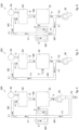
- thermochemical decomposition means M1 comprise a brazier 11 substantially closed with respect to the external environment and delimited by four lateral walls 12 and one upper wall 13. Furthermore, the brazier 11 is delimited at the bottom by a metal plate 14 provided with at least one exit aperture 15.
- the exit aperture 15 of the brazier 11 is also configured to allow the combustible gases S to exit and the burnt and/or thermochemically decomposed biomass C to be discharged from the brazier 11.
- the metal plate 14 can be selectively removable or openable, in any known way, to allow access to the brazier 11 from below, for example to carry out maintenance or cleaning thereof.
- the brazier 11 has an entry aperture 16 for the biomass C to be introduced, comprising, for example, inconsistent wooden material such as chips, pellets or suchlike, and an entry aperture 18 from which the first comburent F1, which is of the aeriform type, can enter.
- the brazier 11 does not have any apertures that allow the comburent air to enter directly from the external environment.
- the entry apertures 16 and 18 of the brazier 11 are disposed in the upper part of the latter, that is, at a higher level than the one at which the exit aperture 15 is located. This configuration allows to introduce the biomass C and the first comburent F1 from the top downward.
- first aperture 16 and of the second aperture 18 may vary compared to that shown in the drawings, so that, for example, one or both can be disposed laterally, or one at a different level from the other.
- the first aperture 16 of the brazier 11 can be disposed substantially level with the lower part thereof.
- the biomass C can be introduced into the brazier 11 from the bottom upward, or, alternatively, laterally, that is, in a substantially horizontal way.
- the first aperture 16 can be disposed substantially level with the metal plate 14, in order to introduce the biomass C directly above the latter.
- an ignition device 19 configured to selectively trigger the combustion of the biomass C, for example when the heating apparatus 10 is switched on.
- the ignition device 19 comprises an electrical resistance disposed in a lower zone of a lateral wall 12, that is, close to the metal plate 14, for example in the same lateral wall 12 in which the first entry aperture 16 is made.
- the ignition device 19 can be sized so as to come into contact, during use, with the biomass C present in the brazier 11. Alternatively, the ignition device 19 can be configured to ignite the biomass C indirectly, that is, by heating the air in contact with the latter.
- the combustion chamber 20 is substantially closed and is in fluidic communication with the brazier 11 by means of a conveyor compartment 21, which is preferably hermetically sealed.
- the conveyor compartment 21 is interposed between the lower part of the brazier 11 and the lower part of the combustion chamber 20.
- the conveyor compartment 21 can be replaced by one or more conduits.
- the brazier 11 and the combustion chamber 20 are autonomous, separated from each other and connected in a fluidic way by means of the conveyor compartment 21.
- the combustion chamber 20 is fluidically connected with the comburent entry aperture 18 of the brazier 11.
- the combustion chamber 20 is delimited by two lateral walls 22, by one upper wall 23, by one front wall 24, for example able to be opened, which functions as closing door, by one rear wall 25 and by one lower wall 26.
- One or more recirculation apertures 27 are made on an upper part of the rear wall 25, each communicating with an upper end of a respective recirculation conduit 28, which is outside the combustion chamber 20 and has a lower end which, by means of a manifold 43, is connected to the intake of a first fan 29, the delivery of which is fluidically connected to the second entry aperture 18 of the brazier 11.
- the recirculation apertures 27 can be made in other walls of the combustion chamber 20.
- the recirculation conduits 28 are substantially parallel to each other and to the rear wall 25, and also detached from each other and from the rear wall 25, for example by between 1 and 3 cm.
- the heating apparatus 10 also comprises a containing body 32, substantially box-shaped, on which two feed apertures 31 are made, which are in communication with the outside and through which the second comburent A can enter.
- the containing body 32 is attached on the external surface of the rear wall 25 of the combustion chamber 20 creating, in cooperation with the latter, a containing compartment V in which the recirculation conduits 28 are disposed.
- An entry aperture 33 is made in the bottom wall 26 of the combustion chamber 20, substantially in a central zone thereof, in said entry aperture 33 there being positioned a nozzle 30 having, in the example given here, a central conduit 34 disposed along a longitudinal axis X, substantially vertical, and a series of lateral through holes 35, which substantially lie on a substantially horizontal plane P disposed below the lower wall 26.
- the lateral holes 35 are in communication with the central conduit 34.
- the central conduit 34 is in communication with the conveyor compartment 21 and has the function of injecting the combustible gases S into the combustion chamber 20, while the lateral holes 35 have the function of conveying the second comburent A, coming from the containing compartment V.
- the second part V2 of the containing compartment V surrounds the portion of the nozzle 30 on which the lateral holes 35 are made, which are configured to receive the second comburent A coming from the second part V2 of the containing compartment V and to promote the mixing of the second comburent A with the combustible gases S in order to promote the combustion of the latter.
- the feed apertures 31 are disposed below the lower ends of the recirculation conduits 28, that is, substantially level with the lower part of the combustion chamber 20.
- a dividing wall, or partition, 37 is disposed inside the containing body 32, substantially dividing the containing compartment V into two parts, that is, into a first part V1, in which the recirculation conduits 28 are disposed, and into a second part V2, which laps both the rear wall 25 and also the lower wall 26 of the combustion chamber 20.
- the first part V1 and the second part V2 of the containing compartment V are in communication with each other in correspondence with the upper part of the partition 37 which, preferably, is disposed in correspondence with the upper ends of the recirculation conduits 28, that is, where the latter are connected to the respective recirculation apertures 27.
- the second comburent A enters from the feed apertures 31, passes through the first part V1 of the containing compartment V and heats up in contact with the recirculation conduits 28, until it reaches the top of the partition, 37. Then, the second comburent A enters the second part V2 of the containing compartment V from above and passes through it all, until it reaches the lateral holes 35 of the nozzle 30, lapping the rear wall 25 of the combustion chamber 20, heating up further.
- the containing body 32 in cooperation with the recirculation conduits 28 and the walls 25 and 27 of the combustion chamber 20, constitutes a counter-current heat exchanger, which corresponds to the heat exchange means M4 as above.
- each of the lateral walls 22 ( fig. 8 ) of the combustion chamber 20 there are evacuation apertures 36, to each of which a respective evacuation pipe 38 is connected, outside the combustion chamber 20 and substantially vertical.
- Each evacuation pipe 38 is fluidically connected to an evacuation chamber 40, in turn connected to the intake of a second fan 39 ( fig. 7 ), the delivery of which communicates with the outside of the apparatus 10.
- the heating apparatus 10 can optionally also comprise an external containing structure 41, substantially in the shape of a parallelepiped and comprising a second compartment 42, inside of which there are disposed, with ample clearance, both the evacuation pipes 38 and also at least a part of the combustion chamber 20, of the conveyor compartment 21 and of the evacuation chamber 40.
- the external structure 41 has, in its lower part, an entry aperture 47, to which a third fan 45 is connected in order to selectively introduce ambient air R into the second compartment 42, and in its upper part an exit aperture 44 from which the same air R can exit in contact with the evacuation pipes 38.
- the heating apparatus 10 also comprises an injection device 46, of any type known per se, to introduce the biomass C into the brazier 11 in a controlled way, whether intermittently or continuously.
- the injection device 46 comprises a container 48, substantially in the shape of a hopper, containing a biomass C load and an associated metering device 49, of a type known per se, having an exit connected to the entry aperture 16 of the brazier 11 and configured to meter the quantity of biomass C introduced into the brazier 11 in a way that is selective and proportional to certain electrical signals, under the control of a control unit 50 ( fig. 11 ), as will be described in detail below.
- the biomass C lies in an autonomous and separate environment with respect to the brazier 11, and it is introduced therein in a selective, automatic and substantially continuous way by the injection device 49.
- the metering device 49 ( fig. 7 ) is of the type which comprises a rotating element 51 provided with radial blades 52 and connected to an electric motor 53 ( fig. 11 ) controlled by the control unit 50. With each rotation, even partial, of the rotating element 51, a certain quantity of biomass C is introduced into the brazier 11, by means of an introduction conduit 54.
- the metering device 49 can comprise an auger.
- the injection device 46 allows to introduce the biomass C into the brazier 11 in an automatic, controlled and continuous way, so as to allow to adjust the flow rate of biomass C introduced into the brazier 11.
- the heating apparatus 10 also comprises a sensor 58 ( figs. 7 and 11 ), also of a type known per se and for example consisting of a lambda probe, which is suitable to detect the quantity of oxygen present in the environment which surrounds it.
- the sensor 58 is positioned downstream of the combustion chamber 20 and in particular inside the evacuation chamber 40.
- the senor 58 can be disposed inside the evacuation pipes 38 and/or inside the recirculation conduits 28 in order to detect the quantity of oxygen in the fumes F.
- the sensor 58 is connected to the control unit 50 and it is configured to transmit to the latter an electrical signal SP proportional to the quantity of oxygen detected by it.
- the control unit 50 is configured to also control the first fan 29 and the second fan 39, and possibly also the third fan 45.
- control unit 50 is configured to command the operation of the recirculation means M2 in order to adjust the flow rate of the first comburent F1, and to command the operation of the injection device 46 in order to control the flow rate of the biomass C introduced into the brazier 11.
- control unit 50 can control the rotation speed of the first fan 29 and consequently the flow rate of the first comburent F1, the rotation speed of the second fan 39 and consequently the flow rate of the second comburent A, and the rotation speed of the rotating element 51 of the metering device 49 and consequently the flow rate of biomass C into the brazier 11.
- an element made of thermoconductive material for example ceramic, can be attached at least to the lateral walls 22 of the combustion chamber 20, in order to increase the thermal inertia.
- one or more pipes for circulating water can be associated with at least the lateral walls 22 of the combustion chamber 20.
- a heating apparatus 100 can comprise all the components of the heating apparatus 10 described above, except the heat exchange means M4.
- the heating apparatus 100 can also comprise a second ignition device, not shown in the drawings, disposed substantially in proximity to the nozzle 30 and configured to trigger the combustion of the combustible gases S.
- a heating apparatus 200 can comprise all the components of the heating apparatus 10 described above, except the heat exchange means M4 and the first fan 29.
- the heating apparatus 200 can also comprise a second ignition device, not shown in the drawings, disposed substantially in proximity to the nozzle 30 and configured to trigger the combustion of the combustible gases S.
- a second ignition device not shown in the drawings, disposed substantially in proximity to the nozzle 30 and configured to trigger the combustion of the combustible gases S.
- a heating apparatus 300 can comprise all the components of the heating apparatus 10 described above, except the first fan 29.
- the heating apparatus 200, 300 only comprises the second fan 39, connected to the combustion chamber 20 in order to draw the fumes F generated inside the latter.
- a conduit connected downstream of the second fan 39 can be connected to the brazier 11 in order to function as a recirculation mean M3 to convey a first part F1 of the fumes F, which functions as a first comburent.
- the conduit described above which functions as a recirculation mean M3 can be disposed upstream of the second fan 39 and downstream of the combustion chamber 20 ( figs. 5 and 6 ).
- the operation of the heating apparatus 10 described heretofore, which corresponds to the method according to the present invention, comprises the following steps.
- control unit 50 drives the injection device 46 to introduce a certain quantity of biomass C into the brazier 11 and the ignition device 19 to ignite the biomass C in the brazier 11.
- control unit 50 drives the first fan 29 which takes a first comburent F1 from the combustion chamber 20 and introduces it into the brazier 11.
- the control unit 50 also drives the second fan 39 which draws the second comburent A from the external environment, through the feed apertures 31, and introduces the latter into the combustion chamber 20 through its entry aperture 33.
- start-up combustion the combustion between the biomass C inside the brazier 11 and the first comburent F1 which hereafter will be referred to as start-up combustion, is substantially of the reverse flame type, also called downdraft by the people of skill in the art, that is, by introducing the first comburent F1 into the brazier 11 from the top downward, in such a way that it passes, in this direction, through the biomass C disposed, during use, in the brazier 11 and consequently generating a flame which is also directed from the top downward, and fumes.
- reverse flame type also called downdraft
- the first comburent F1 consists of a first part of the start-up combustion fumes.
- a first part F1 of the start-up combustion fumes is drawn by the first fan 29 by means of the first recirculation apertures 27 and is re-introduced into the brazier 11 from its second aperture 18, functioning as first comburent F1
- a second part F2 of the start-up combustion fumes is drawn in by the second fan 39 by means of the evacuation apertures 36 and is expelled from the heating apparatus 10.
- the first comburent F1 has a temperature and quantity of oxygen suitable to trigger the process of pyrolysis of the biomass C present in the brazier 11.
- the first comburent F1 introduced into the brazier 11 is suitable to thermochemically decompose the biomass C inside the brazier 11 and produce combustible gases S.
- thermochemical decomposition of the biomass C also substantially occurs in downdraft, that is, by introducing the first comburent F1 into the brazier 11 from the top downward, in such a way that it passes, in this direction, through the biomass C which is disposed, during use, in the brazier 11. In this way, the combustible gases S produced by the thermochemical decomposition of the biomass C escape from the lower portion of the brazier 11.
- This configuration is advantageous in that it forces the combustible gases S to pass through the biomass C contained in the brazier 11 and this allows to separate their volatile components, producing combustible gases S with less TAR.
- the method then provides to introduce the combustible gases S into the combustion chamber 20 by means of the conveyor compartment 21, thanks to the draw of the first fan 29.
- the conveyor means M2 when operating at steady state, only the combustible gases S pass through the conveyor compartment 21
- the first part F1 of the fumes F, re-introduced into the brazier 11, and which in fact functions as first comburent F1 has an oxygen component advantageously comprised between about 7% and about 12% by volume, which is smaller than that present in the ambient air. This is particularly advantageous since, by doing so, an anoxic environment is created in the brazier 11, that is, lacking in oxygen, which is present in a quantity sufficient to react mainly with the carbon present in the biomass C and generate the combustible gases.
- the first part F1 of the fumes F when operating at steady state, the first part F1 of the fumes F, the moment it enters the brazier 11, has a temperature comprised between about 240°C and about 320°C, this is advantageous since at least part of the CO 2 present therein is re-converted into CO, that is, carbon monoxide, which is combustible.
- Another advantage is that the water present in gaseous phase in the first part F1 of the fumes F in the brazier 11 is converted into hydrogen, increasing the calorific value of the combustible gas S.
- the control unit 50 can also control the injection device 46, the first fan 29 and the second fan 39 on the basis of the electrical signal received from the sensor 58.
- the control unit 50 can modify the flow rate of the first comburent F1, of the second comburent A and/or of the biomass C in feedback, until the value detected by the sensor 58 reaches a predetermined target value.
- the injection device 46, the first fan 29 and the second fan 39 allow to manage the flow rate of the first comburent F1, of the second comburent A and/or of the biomass C in a coordinated way, so as to reduce the polluting emissions of the heating apparatus 10 and better manage the generation of heat thereby.
- control unit 50 also drives the third fan 45 to generate a flow of ambient air R which passes into the second compartment 42 in order to exchange heat with the evacuation pipes 38, heating up.
- the heated ambient air R is then conveyed once again toward the external environment.
Landscapes
- Engineering & Computer Science (AREA)
- Mechanical Engineering (AREA)
- General Engineering & Computer Science (AREA)
- Chemical & Material Sciences (AREA)
- Combustion & Propulsion (AREA)
- Physics & Mathematics (AREA)
- Thermal Sciences (AREA)
- Solid-Fuel Combustion (AREA)
- Control And Other Processes For Unpacking Of Materials (AREA)
- Glass Compositions (AREA)
Claims (8)
- Heizvorrichtung (10, 100, 200, 300), die einen Brenner (11) umfasst, der so konfiguriert ist, dass er eine Biomasse (C), die als Brennstoff dient, und ein erstes Brennmittel (F1) aufnimmt und geeignet ist, die Biomasse (C) thermisch zu zersetzen und mindestens ein brennbares Gas (S) zu erzeugen, wobei der Brenner (11) von der Art ist, die gegenüber der äußeren Umgebung im Wesentlichen geschlossen ist, so dass der Brenner (11) keinerlei Öffnungen aufweist, durch die das luftartige Brennmittel direkt von der äußeren Umgebung eintreten kann, wobei der Brenner (11) eine erste Eintrittsöffnung (16) umfasst, die mit einer Einspritzvorrichtung (46) verbunden ist, die so konfiguriert ist, dass sie auf kontrollierte, automatische, kontinuierliche und einstellbare Weise die Biomasse (C) in den Brenner (11) einführt, wobei der Brenner (11) eine zweite Eintrittsöffnung (18) für den Eintritt des ersten Brennmittels (F1) und eine Austrittsöffnung (15) für den Austritt des mindestens einen brennbaren Gases (S) umfasst, wobei die Austrittsöffnung (15) auf einem niedrigeren Niveau angeordnet ist als dasjenige, auf dem zumindest die zweite Eintrittsöffnung (18) angeordnet ist, wobei die erste und zweite Eintrittsöffnung (16, 18) des Brenners (11) auf einem höheren Niveau angeordnet sind als dasjenige, auf dem die Austrittsöffnung (15) angeordnet ist, so dass das erste Brennmittel (F1) und die Biomasse (C) von oben nach unten und in Richtung der Austrittsöffnung (15) in den Brenner (11) eintreten.
- Heizvorrichtung (10, 100, 200, 300) nach Anspruch 1, welche außerdem eine Brennkammer (20) umfasst, die in Bezug auf den Brenner (11) autonom ist und ihre eigene Eintrittsöffnung (33) aufweist, die so konfiguriert ist, dass sie das brennbare Gas (S) aufnimmt, sowie Fördermittel (M2), die zwischen dem Brenner (11) und der Eintrittsöffnung (33) der Brennkammer (20) angeordnet sind, um das mindestens eine brennbare Gas (S) in die Brennkammer (20) zu befördern.
- Heizvorrichtung (10, 100, 200, 300) nach einem der vorhergehenden Ansprüche, welche außerdem eine Steuereinheit (50) umfasst, die so konfiguriert ist, dass sie die Einspritzvorrichtung (46) steuert, um die Durchflussmenge der in den Brenner (11) eingeführten Biomasse (C) einzustellen.
- Heizvorrichtung (10, 100, 200, 300) nach Anspruch 2 oder 3, wobei die Eintrittsöffnung (33) der Brennkammer (20) so konfiguriert ist, dass sie ein zweites Brennmittel (A) aus der äußeren Umgebung aufnimmt, und wobei die Heizvorrichtung (10, 100, 200, 300) außerdem sowohl Rezirkulationsmittel (M3), um das erste Brennmittel (F1) aus der Brennkammer (20) in den Brenner (11) zu befördern, als auch ein Gebläse (39), das mit einer Evakuierungsöffnung (36) der Brennkammer (20) verbunden und so konfiguriert ist, dass es das zweite Brennmittel (A) aus der äußeren Umgebung in das Innere der Brennkammer (20) drückt, umfasst.
- Heizverfahren, das die Heizvorrichtung gemäß irgendeinem der vorstehenden Ansprüche verwendet, wobei das Verfahren die folgenden Schritte umfasst:- Bereitstellen des Brenners (11);- Einführen sowohl der Biomasse (C) als auch des ersten Brennmittels (F1) in den Brenner (11), um die Biomasse (C) thermochemisch zu zersetzen und mindestens ein brennbares Gas (S) zu erzeugen.
- Heizverfahren nach Anspruch 5, welches außerdem die folgenden Schritte umfasst:- Bereitstellen einer Brennkammer (20), die in Bezug auf den Brenner (11) autonom ist;- Zuführen des brennbaren Gases (S) in die Brennkammer (20);- Entnahme eines zweiten Brennmittels (A) aus der äußeren Umgebung und Befördern desselben in die Brennkammer (20); und- Zünden des brennbaren Gases (S), um mittels einer Flamme Wärme zu entwickeln.
- Heizverfahren nach Anspruch 6, welches außerdem die folgenden Schritte umfasst:- Abziehen eines ersten Teils (F1) der von der Flamme erzeugten Abgase (F) aus der Brennkammer (20) und Einleiten derselben in den Brenner (11), wobei der erste Teil (F1) der Abgase (F) das erste Brennmittel (F1) bildet; und- Abziehen eines zweiten Teils (F2) der Abgase (F) aus der Brennkammer (20), um sie in die äußere Umgebung zu evakuieren.
- Heizverfahren nach einem der Ansprüche 5 bis 7, wobei die Biomasse (C) im Wesentlichen kontinuierlich in den Brenner (11) eingeführt wird.
Applications Claiming Priority (2)
| Application Number | Priority Date | Filing Date | Title |
|---|---|---|---|
| IT102021000007769A IT202100007769A1 (it) | 2021-03-30 | 2021-03-30 | Apparecchiatura di riscaldamento |
| PCT/IT2022/050078 WO2022208566A1 (en) | 2021-03-30 | 2022-03-30 | Heating apparatus |
Publications (3)
| Publication Number | Publication Date |
|---|---|
| EP4314647A1 EP4314647A1 (de) | 2024-02-07 |
| EP4314647B1 true EP4314647B1 (de) | 2025-04-16 |
| EP4314647C0 EP4314647C0 (de) | 2025-04-16 |
Family
ID=76375550
Family Applications (1)
| Application Number | Title | Priority Date | Filing Date |
|---|---|---|---|
| EP22720518.4A Active EP4314647B1 (de) | 2021-03-30 | 2022-03-30 | Heizgerät und verfahren zu dessen verwendung |
Country Status (3)
| Country | Link |
|---|---|
| EP (1) | EP4314647B1 (de) |
| IT (1) | IT202100007769A1 (de) |
| WO (1) | WO2022208566A1 (de) |
Family Cites Families (3)
| Publication number | Priority date | Publication date | Assignee | Title |
|---|---|---|---|---|
| DE3718022C1 (en) * | 1987-05-27 | 1988-11-10 | Kernforschungsanlage Juelich | Boiler burning solid matter |
| FR2752915A1 (fr) * | 1996-08-29 | 1998-03-06 | Miquee Max | Chaudiere double combustion a tirage inverse |
| WO2014064300A1 (es) * | 2012-10-23 | 2014-05-01 | Fundación Cidaut | Caldera vertical de combustible sólido |
-
2021
- 2021-03-30 IT IT102021000007769A patent/IT202100007769A1/it unknown
-
2022
- 2022-03-30 WO PCT/IT2022/050078 patent/WO2022208566A1/en not_active Ceased
- 2022-03-30 EP EP22720518.4A patent/EP4314647B1/de active Active
Also Published As
| Publication number | Publication date |
|---|---|
| EP4314647C0 (de) | 2025-04-16 |
| WO2022208566A1 (en) | 2022-10-06 |
| EP4314647A1 (de) | 2024-02-07 |
| IT202100007769A1 (it) | 2022-09-30 |
Similar Documents
| Publication | Publication Date | Title |
|---|---|---|
| JP6653862B2 (ja) | 発火装置における燃焼管理のための方法および発火装置 | |
| JPS59217411A (ja) | 可燃物の燃焼のための方法及び排ガスの燃焼のための燃焼室 | |
| EP2537912B1 (de) | Vorrichtung und Verfahren zum thermochemischen Abbau von Biomasse in einem fortlaufenden Zyklus | |
| CN109641745A (zh) | 利用燃料添加进行的热化学再生 | |
| EP4314649B1 (de) | Heizgerät und verfahren zu dessen verwendung | |
| EP4314646B1 (de) | Heizgerät und verfahren zu dessen verwendung | |
| RU2439437C1 (ru) | Газогенераторное отопительное устройство | |
| WO2010135326A2 (en) | Gasification combustion system | |
| FI127234B (fi) | Menetelmä ja laite kiinteiden polttoaineiden tulisijassa polttamisen tehostamiseksi | |
| WO2022208566A1 (en) | Heating apparatus | |
| KR101924345B1 (ko) | 종합폐기물 일괄투입 가스화 고온 연소장치 및 이의 제어방법 | |
| CN211204412U (zh) | 一种应用热解法的甲醇等离子锅炉装置 | |
| EP2314918A2 (de) | Vorrichtung zur Vergasung und Verbrennung von festem Brennstoff | |
| TWI762399B (zh) | 環保生質燃料之燃燒爐 | |
| US3776148A (en) | Incinerator | |
| CN201141018Y (zh) | 燃煤秸秆喷嘴式多功能气化炉 | |
| JP2004116818A (ja) | 焼却炉及び焼却方法 | |
| JP4419743B2 (ja) | 乾留焼却炉 | |
| CN217899872U (zh) | 一种立式生活垃圾气化焚烧装置 | |
| RU98534U1 (ru) | Газогенераторное отопительное устройство | |
| US20030200905A1 (en) | Process for making a gas from solid fuels and burning the gas in a close coupled combustor to produce clean heat | |
| WO2011013017A1 (en) | A plant for molecular dissociation of waste material | |
| UA23254U (en) | Furnace on solid fuel | |
| JP2000111022A (ja) | ごみ焼却炉におけるダイオキシン類の除去方法 | |
| CN210267346U (zh) | 带横向喷火燃烧灶的垃圾气化子母炉设备 |
Legal Events
| Date | Code | Title | Description |
|---|---|---|---|
| STAA | Information on the status of an ep patent application or granted ep patent |
Free format text: STATUS: UNKNOWN |
|
| STAA | Information on the status of an ep patent application or granted ep patent |
Free format text: STATUS: THE INTERNATIONAL PUBLICATION HAS BEEN MADE |
|
| PUAI | Public reference made under article 153(3) epc to a published international application that has entered the european phase |
Free format text: ORIGINAL CODE: 0009012 |
|
| STAA | Information on the status of an ep patent application or granted ep patent |
Free format text: STATUS: REQUEST FOR EXAMINATION WAS MADE |
|
| 17P | Request for examination filed |
Effective date: 20231003 |
|
| AK | Designated contracting states |
Kind code of ref document: A1 Designated state(s): AL AT BE BG CH CY CZ DE DK EE ES FI FR GB GR HR HU IE IS IT LI LT LU LV MC MK MT NL NO PL PT RO RS SE SI SK SM TR |
|
| P01 | Opt-out of the competence of the unified patent court (upc) registered |
Effective date: 20240219 |
|
| DAV | Request for validation of the european patent (deleted) | ||
| DAX | Request for extension of the european patent (deleted) | ||
| GRAP | Despatch of communication of intention to grant a patent |
Free format text: ORIGINAL CODE: EPIDOSNIGR1 |
|
| STAA | Information on the status of an ep patent application or granted ep patent |
Free format text: STATUS: GRANT OF PATENT IS INTENDED |
|
| INTG | Intention to grant announced |
Effective date: 20241126 |
|
| GRAS | Grant fee paid |
Free format text: ORIGINAL CODE: EPIDOSNIGR3 |
|
| GRAA | (expected) grant |
Free format text: ORIGINAL CODE: 0009210 |
|
| STAA | Information on the status of an ep patent application or granted ep patent |
Free format text: STATUS: THE PATENT HAS BEEN GRANTED |
|
| AK | Designated contracting states |
Kind code of ref document: B1 Designated state(s): AL AT BE BG CH CY CZ DE DK EE ES FI FR GB GR HR HU IE IS IT LI LT LU LV MC MK MT NL NO PL PT RO RS SE SI SK SM TR |
|
| REG | Reference to a national code |
Ref country code: GB Ref legal event code: FG4D |
|
| REG | Reference to a national code |
Ref country code: CH Ref legal event code: EP Ref country code: DE Ref legal event code: R096 Ref document number: 602022013261 Country of ref document: DE |
|
| REG | Reference to a national code |
Ref country code: IE Ref legal event code: FG4D |
|
| U01 | Request for unitary effect filed |
Effective date: 20250423 |
|
| U07 | Unitary effect registered |
Designated state(s): AT BE BG DE DK EE FI FR IT LT LU LV MT NL PT RO SE SI Effective date: 20250429 |
|
| P04 | Withdrawal of opt-out of the competence of the unified patent court (upc) registered |
Free format text: CASE NUMBER: APP_19832/2025 Effective date: 20250425 |
|
| PG25 | Lapsed in a contracting state [announced via postgrant information from national office to epo] |
Ref country code: ES Free format text: LAPSE BECAUSE OF FAILURE TO SUBMIT A TRANSLATION OF THE DESCRIPTION OR TO PAY THE FEE WITHIN THE PRESCRIBED TIME-LIMIT Effective date: 20250416 |
|
| PG25 | Lapsed in a contracting state [announced via postgrant information from national office to epo] |
Ref country code: GR Free format text: LAPSE BECAUSE OF FAILURE TO SUBMIT A TRANSLATION OF THE DESCRIPTION OR TO PAY THE FEE WITHIN THE PRESCRIBED TIME-LIMIT Effective date: 20250717 Ref country code: NO Free format text: LAPSE BECAUSE OF FAILURE TO SUBMIT A TRANSLATION OF THE DESCRIPTION OR TO PAY THE FEE WITHIN THE PRESCRIBED TIME-LIMIT Effective date: 20250716 |
|
| PG25 | Lapsed in a contracting state [announced via postgrant information from national office to epo] |
Ref country code: PL Free format text: LAPSE BECAUSE OF FAILURE TO SUBMIT A TRANSLATION OF THE DESCRIPTION OR TO PAY THE FEE WITHIN THE PRESCRIBED TIME-LIMIT Effective date: 20250416 |
|
| PG25 | Lapsed in a contracting state [announced via postgrant information from national office to epo] |
Ref country code: HR Free format text: LAPSE BECAUSE OF FAILURE TO SUBMIT A TRANSLATION OF THE DESCRIPTION OR TO PAY THE FEE WITHIN THE PRESCRIBED TIME-LIMIT Effective date: 20250416 |
|
| PG25 | Lapsed in a contracting state [announced via postgrant information from national office to epo] |
Ref country code: RS Free format text: LAPSE BECAUSE OF FAILURE TO SUBMIT A TRANSLATION OF THE DESCRIPTION OR TO PAY THE FEE WITHIN THE PRESCRIBED TIME-LIMIT Effective date: 20250716 |
|
| PG25 | Lapsed in a contracting state [announced via postgrant information from national office to epo] |
Ref country code: IS Free format text: LAPSE BECAUSE OF FAILURE TO SUBMIT A TRANSLATION OF THE DESCRIPTION OR TO PAY THE FEE WITHIN THE PRESCRIBED TIME-LIMIT Effective date: 20250816 |
|
| PG25 | Lapsed in a contracting state [announced via postgrant information from national office to epo] |
Ref country code: SM Free format text: LAPSE BECAUSE OF FAILURE TO SUBMIT A TRANSLATION OF THE DESCRIPTION OR TO PAY THE FEE WITHIN THE PRESCRIBED TIME-LIMIT Effective date: 20250416 |
|
| PG25 | Lapsed in a contracting state [announced via postgrant information from national office to epo] |
Ref country code: CZ Free format text: LAPSE BECAUSE OF FAILURE TO SUBMIT A TRANSLATION OF THE DESCRIPTION OR TO PAY THE FEE WITHIN THE PRESCRIBED TIME-LIMIT Effective date: 20250416 |
|
| PG25 | Lapsed in a contracting state [announced via postgrant information from national office to epo] |
Ref country code: SK Free format text: LAPSE BECAUSE OF FAILURE TO SUBMIT A TRANSLATION OF THE DESCRIPTION OR TO PAY THE FEE WITHIN THE PRESCRIBED TIME-LIMIT Effective date: 20250416 |
|
| PLBE | No opposition filed within time limit |
Free format text: ORIGINAL CODE: 0009261 |
|
| STAA | Information on the status of an ep patent application or granted ep patent |
Free format text: STATUS: NO OPPOSITION FILED WITHIN TIME LIMIT |
|
| REG | Reference to a national code |
Ref country code: CH Ref legal event code: L10 Free format text: ST27 STATUS EVENT CODE: U-0-0-L10-L00 (AS PROVIDED BY THE NATIONAL OFFICE) Effective date: 20260225 |
|
| 26N | No opposition filed |
Effective date: 20260119 |
|
| U20 | Renewal fee for the european patent with unitary effect paid |
Year of fee payment: 5 Effective date: 20260310 |