EP2314918A2 - Vorrichtung zur Vergasung und Verbrennung von festem Brennstoff - Google Patents
Vorrichtung zur Vergasung und Verbrennung von festem Brennstoff Download PDFInfo
- Publication number
- EP2314918A2 EP2314918A2 EP10396005A EP10396005A EP2314918A2 EP 2314918 A2 EP2314918 A2 EP 2314918A2 EP 10396005 A EP10396005 A EP 10396005A EP 10396005 A EP10396005 A EP 10396005A EP 2314918 A2 EP2314918 A2 EP 2314918A2
- Authority
- EP
- European Patent Office
- Prior art keywords
- combustion
- tube
- space
- grate
- air inlet
- Prior art date
- Legal status (The legal status is an assumption and is not a legal conclusion. Google has not performed a legal analysis and makes no representation as to the accuracy of the status listed.)
- Withdrawn
Links
- 238000002485 combustion reaction Methods 0.000 title claims abstract description 77
- 238000002309 gasification Methods 0.000 title claims abstract description 24
- 239000004449 solid propellant Substances 0.000 title claims abstract description 19
- 238000005192 partition Methods 0.000 claims abstract description 14
- 239000000446 fuel Substances 0.000 claims description 42
- 230000005484 gravity Effects 0.000 claims description 2
- 229910010293 ceramic material Inorganic materials 0.000 claims 1
- 239000007789 gas Substances 0.000 description 27
- 239000008188 pellet Substances 0.000 description 16
- UGFAIRIUMAVXCW-UHFFFAOYSA-N Carbon monoxide Chemical compound [O+]#[C-] UGFAIRIUMAVXCW-UHFFFAOYSA-N 0.000 description 8
- 238000010438 heat treatment Methods 0.000 description 8
- 239000003546 flue gas Substances 0.000 description 6
- 229910000851 Alloy steel Inorganic materials 0.000 description 3
- 239000000919 ceramic Substances 0.000 description 3
- 230000007423 decrease Effects 0.000 description 3
- MWUXSHHQAYIFBG-UHFFFAOYSA-N nitrogen oxide Inorganic materials O=[N] MWUXSHHQAYIFBG-UHFFFAOYSA-N 0.000 description 3
- 230000003287 optical effect Effects 0.000 description 3
- 230000001105 regulatory effect Effects 0.000 description 3
- 239000000779 smoke Substances 0.000 description 3
- XLYOFNOQVPJJNP-UHFFFAOYSA-N water Substances O XLYOFNOQVPJJNP-UHFFFAOYSA-N 0.000 description 3
- 239000002023 wood Substances 0.000 description 3
- 229910000831 Steel Inorganic materials 0.000 description 2
- QVGXLLKOCUKJST-UHFFFAOYSA-N atomic oxygen Chemical compound [O] QVGXLLKOCUKJST-UHFFFAOYSA-N 0.000 description 2
- 230000008901 benefit Effects 0.000 description 2
- 238000007664 blowing Methods 0.000 description 2
- 229910002091 carbon monoxide Inorganic materials 0.000 description 2
- 230000000694 effects Effects 0.000 description 2
- 238000000034 method Methods 0.000 description 2
- 239000001301 oxygen Substances 0.000 description 2
- 229910052760 oxygen Inorganic materials 0.000 description 2
- 230000004044 response Effects 0.000 description 2
- 239000010959 steel Substances 0.000 description 2
- 238000010408 sweeping Methods 0.000 description 2
- 230000007704 transition Effects 0.000 description 2
- 229910001018 Cast iron Inorganic materials 0.000 description 1
- UFHFLCQGNIYNRP-UHFFFAOYSA-N Hydrogen Chemical compound [H][H] UFHFLCQGNIYNRP-UHFFFAOYSA-N 0.000 description 1
- 230000009471 action Effects 0.000 description 1
- 230000003213 activating effect Effects 0.000 description 1
- 229910045601 alloy Inorganic materials 0.000 description 1
- 239000000956 alloy Substances 0.000 description 1
- 239000010419 fine particle Substances 0.000 description 1
- 238000010304 firing Methods 0.000 description 1
- 239000003500 flue dust Substances 0.000 description 1
- 239000001257 hydrogen Substances 0.000 description 1
- 229910052739 hydrogen Inorganic materials 0.000 description 1
- 238000009413 insulation Methods 0.000 description 1
- 229910052751 metal Inorganic materials 0.000 description 1
- 239000002184 metal Substances 0.000 description 1
- 238000012806 monitoring device Methods 0.000 description 1
- 239000002245 particle Substances 0.000 description 1
- 230000005855 radiation Effects 0.000 description 1
- 239000004071 soot Substances 0.000 description 1
- 230000002459 sustained effect Effects 0.000 description 1
Images



Classifications
-
- C—CHEMISTRY; METALLURGY
- C10—PETROLEUM, GAS OR COKE INDUSTRIES; TECHNICAL GASES CONTAINING CARBON MONOXIDE; FUELS; LUBRICANTS; PEAT
- C10J—PRODUCTION OF PRODUCER GAS, WATER-GAS, SYNTHESIS GAS FROM SOLID CARBONACEOUS MATERIAL, OR MIXTURES CONTAINING THESE GASES; CARBURETTING AIR OR OTHER GASES
- C10J3/00—Production of combustible gases containing carbon monoxide from solid carbonaceous fuels
- C10J3/02—Fixed-bed gasification of lump fuel
- C10J3/20—Apparatus; Plants
- C10J3/34—Grates; Mechanical ash-removing devices
- C10J3/40—Movable grates
-
- F—MECHANICAL ENGINEERING; LIGHTING; HEATING; WEAPONS; BLASTING
- F23—COMBUSTION APPARATUS; COMBUSTION PROCESSES
- F23G—CREMATION FURNACES; CONSUMING WASTE PRODUCTS BY COMBUSTION
- F23G5/00—Incineration of waste; Incinerator constructions; Details, accessories or control therefor
- F23G5/02—Incineration of waste; Incinerator constructions; Details, accessories or control therefor with pretreatment
- F23G5/027—Incineration of waste; Incinerator constructions; Details, accessories or control therefor with pretreatment pyrolising or gasifying stage
-
- F—MECHANICAL ENGINEERING; LIGHTING; HEATING; WEAPONS; BLASTING
- F23—COMBUSTION APPARATUS; COMBUSTION PROCESSES
- F23G—CREMATION FURNACES; CONSUMING WASTE PRODUCTS BY COMBUSTION
- F23G5/00—Incineration of waste; Incinerator constructions; Details, accessories or control therefor
- F23G5/24—Incineration of waste; Incinerator constructions; Details, accessories or control therefor having a vertical, substantially cylindrical, combustion chamber
- F23G5/245—Incineration of waste; Incinerator constructions; Details, accessories or control therefor having a vertical, substantially cylindrical, combustion chamber with perforated bottom or grate
-
- C—CHEMISTRY; METALLURGY
- C10—PETROLEUM, GAS OR COKE INDUSTRIES; TECHNICAL GASES CONTAINING CARBON MONOXIDE; FUELS; LUBRICANTS; PEAT
- C10J—PRODUCTION OF PRODUCER GAS, WATER-GAS, SYNTHESIS GAS FROM SOLID CARBONACEOUS MATERIAL, OR MIXTURES CONTAINING THESE GASES; CARBURETTING AIR OR OTHER GASES
- C10J2200/00—Details of gasification apparatus
- C10J2200/09—Mechanical details of gasifiers not otherwise provided for, e.g. sealing means
-
- C—CHEMISTRY; METALLURGY
- C10—PETROLEUM, GAS OR COKE INDUSTRIES; TECHNICAL GASES CONTAINING CARBON MONOXIDE; FUELS; LUBRICANTS; PEAT
- C10J—PRODUCTION OF PRODUCER GAS, WATER-GAS, SYNTHESIS GAS FROM SOLID CARBONACEOUS MATERIAL, OR MIXTURES CONTAINING THESE GASES; CARBURETTING AIR OR OTHER GASES
- C10J2200/00—Details of gasification apparatus
- C10J2200/15—Details of feeding means
-
- C—CHEMISTRY; METALLURGY
- C10—PETROLEUM, GAS OR COKE INDUSTRIES; TECHNICAL GASES CONTAINING CARBON MONOXIDE; FUELS; LUBRICANTS; PEAT
- C10J—PRODUCTION OF PRODUCER GAS, WATER-GAS, SYNTHESIS GAS FROM SOLID CARBONACEOUS MATERIAL, OR MIXTURES CONTAINING THESE GASES; CARBURETTING AIR OR OTHER GASES
- C10J2300/00—Details of gasification processes
- C10J2300/09—Details of the feed, e.g. feeding of spent catalyst, inert gas or halogens
- C10J2300/0903—Feed preparation
-
- C—CHEMISTRY; METALLURGY
- C10—PETROLEUM, GAS OR COKE INDUSTRIES; TECHNICAL GASES CONTAINING CARBON MONOXIDE; FUELS; LUBRICANTS; PEAT
- C10J—PRODUCTION OF PRODUCER GAS, WATER-GAS, SYNTHESIS GAS FROM SOLID CARBONACEOUS MATERIAL, OR MIXTURES CONTAINING THESE GASES; CARBURETTING AIR OR OTHER GASES
- C10J2300/00—Details of gasification processes
- C10J2300/09—Details of the feed, e.g. feeding of spent catalyst, inert gas or halogens
- C10J2300/0913—Carbonaceous raw material
- C10J2300/0916—Biomass
-
- C—CHEMISTRY; METALLURGY
- C10—PETROLEUM, GAS OR COKE INDUSTRIES; TECHNICAL GASES CONTAINING CARBON MONOXIDE; FUELS; LUBRICANTS; PEAT
- C10J—PRODUCTION OF PRODUCER GAS, WATER-GAS, SYNTHESIS GAS FROM SOLID CARBONACEOUS MATERIAL, OR MIXTURES CONTAINING THESE GASES; CARBURETTING AIR OR OTHER GASES
- C10J2300/00—Details of gasification processes
- C10J2300/09—Details of the feed, e.g. feeding of spent catalyst, inert gas or halogens
- C10J2300/0953—Gasifying agents
- C10J2300/0956—Air or oxygen enriched air
-
- C—CHEMISTRY; METALLURGY
- C10—PETROLEUM, GAS OR COKE INDUSTRIES; TECHNICAL GASES CONTAINING CARBON MONOXIDE; FUELS; LUBRICANTS; PEAT
- C10J—PRODUCTION OF PRODUCER GAS, WATER-GAS, SYNTHESIS GAS FROM SOLID CARBONACEOUS MATERIAL, OR MIXTURES CONTAINING THESE GASES; CARBURETTING AIR OR OTHER GASES
- C10J2300/00—Details of gasification processes
- C10J2300/12—Heating the gasifier
- C10J2300/1269—Heating the gasifier by radiating device, e.g. radiant tubes
- C10J2300/1276—Heating the gasifier by radiating device, e.g. radiant tubes by electricity, e.g. resistor heating
-
- C—CHEMISTRY; METALLURGY
- C10—PETROLEUM, GAS OR COKE INDUSTRIES; TECHNICAL GASES CONTAINING CARBON MONOXIDE; FUELS; LUBRICANTS; PEAT
- C10J—PRODUCTION OF PRODUCER GAS, WATER-GAS, SYNTHESIS GAS FROM SOLID CARBONACEOUS MATERIAL, OR MIXTURES CONTAINING THESE GASES; CARBURETTING AIR OR OTHER GASES
- C10J2300/00—Details of gasification processes
- C10J2300/16—Integration of gasification processes with another plant or parts within the plant
- C10J2300/1603—Integration of gasification processes with another plant or parts within the plant with gas treatment
- C10J2300/1606—Combustion processes
-
- F—MECHANICAL ENGINEERING; LIGHTING; HEATING; WEAPONS; BLASTING
- F23—COMBUSTION APPARATUS; COMBUSTION PROCESSES
- F23G—CREMATION FURNACES; CONSUMING WASTE PRODUCTS BY COMBUSTION
- F23G2201/00—Pretreatment
- F23G2201/30—Pyrolysing
- F23G2201/303—Burning pyrogases
-
- F—MECHANICAL ENGINEERING; LIGHTING; HEATING; WEAPONS; BLASTING
- F23—COMBUSTION APPARATUS; COMBUSTION PROCESSES
- F23G—CREMATION FURNACES; CONSUMING WASTE PRODUCTS BY COMBUSTION
- F23G2203/00—Furnace arrangements
- F23G2203/40—Stationary bed furnace
- F23G2203/401—Stationary bed furnace with support for a grate or perforated plate
Definitions
- the present invention relates to a combustion device for gasification and combustion of solid fuel, in particular to a pellet or chip burner, of the type having a grate which receives the solid fuel, a primary air inlet arrangement which provides air to the grate for gasification of the solid fuel to form product gas, and a secondary air inlet arrangement for blowing a stream of air into a combustion tube in order to draw product gas into the combustion tube and lower the pressure in the reactor space.
- a typical pellet or chip heating system includes a boiler with water circulation, a fuel burner, and a system for storing and transferring fuel.
- the boiler can be designed for an oil burner or can be intended particularly for combustion of solid fuel, such as a multi-fuel boiler or a boiler designed particularly for burning of fuel.
- the known pellet burners can be divided into three different main types depending on the feed inlet of fuel: under-feed burners, horizontal feed burners and overfeed burners. In under-feed burners the fuel is fed to the combustion chamber from below, in which case they are forced through the whole combustion zone. In horizontal feed burners the fuel ise fed to the combustion space from the side, and in overfeed burners the fuel is dropped into the combustion space from above.
- US 6,336,449 and CH 654 899 present solutions applicable particularly to vacuum-operated combustion or gasification of particle-like solid fuels, such as pellets or chips, wherein solid fuel is gasified in a reactor on a grate by feeding gasification air in connection therewith by means of a primary air inlet arrangement, and product gas produced as a result of the gasification is fed in the combustion device into a tube-like combustion channel into which secondary air is fed for combustion of the product gas.
- US 2,354,963 discloses a combustion device and method for gasification and combustion of solid fuel, typically wood chips, wherein the combustion device has a reactor space, a reactor provided with a grate for gasification of the solid fuel, a primary air inlet arrangement for feeding of gasification air in connection with the grate, and a secondary air inlet arrangement including a nozzle for blowing a jet of air into a venturi-shaped combustion channel, in order to burn the product gas generated during gasification.
- a partial vacuum is produced in the reactor space by the jet of air, which sucks along product gas from the reactor space to cause a so-called ejector action according to Bernoulli's principle. Note that this device would not be suitable for burning pellets, because of the high temperatures in the feed column, which would cause pellets to disintegrate long before they reach the grate.
- an enclosure is separated into an upper space and a lower space by a partition having a hole which provides essentially the only passage for flow of gas from the lower space to the upper space.
- a reactor tube having an open upper end in the upper space and an open lower end is supported by the partition over the hole, and a grate is located in the lower space below the hole.
- a primary air inlet is arranged to feed air into the lower space for gasification of solid fuel on the grate.
- a combustion tube fixed to the enclosure has an open inlet end communicating with the upper space and an open exhaust end outside the enclosure.
- a secondary air inlet is arranged to direct a stream of air toward the inlet end of the combustion tube, whereby product gas formed by gasification of solid fuel on the grate and passing through the reactor tube into the upper space will be drawn into the combustion tube to create a sub-atmospheric pressure in the upper space.
- the combustion device according to the invention is simple and efficient, due in particular to the separate cylindrical reactor tube placed vertically on the partition and open at both ends, enabling an optimum gasification of the fuel in a reactor tube that is spaced from exterior walls of the reactor space.
- outside surface temperatures of the combustion device can be minimized and the efficiency can be significantly improved.
- Fuel are fed to the grate as needed in response to an optical detector in the top of a pellet feed chute over the reactor tube, and are not piled high over the grate, so that they are not highly heated prior to being fed and do not disintegrate. This represents an important advantage over Ohlsson US 2,354,963 .
- the invention furthermore has the advantage that the rate of product gas being gasified from the solid fuel will increase, so that higher flame and radiation temperatures in the combustion tube will be achieved. Further, the shape of the burner's flame has a wide cross section and is elongated, so it is useful in many kinds of boilers. Also, very little flue dust is generated, which reduces particulate emission of the burner so that the need for chimney sweeping of the smoke flue also decreases.
- the combustion process of the combustion device according to the invention is more like an oil burner than traditional pellet burners, whereby it offers a viable alternative when renewing heating systems.
- Figure 1 is a cross-section of the combustion device according to the invention showing the reactor tube and the fuel feed chute;
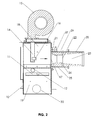
- Figure 2 is a cross-section showing the secondary air inlet and the combustion tube
- Figure 3 is a side view of the combustion device
- Figure 4 is another side view, as seen from the right side of Figure 3 ;
- Figure 5 is a top view of the combustion device.
- the combustion device includes an enclosure 10 having walls formed of steel sheet or cast iron and fastened to a frame in known fashion.
- the walls may be coated on the inside and/or the outside with thermal insulation.
- the partition 12 has a hole 13 which provides essentially the only passage for flow of gas from the lower space to the upper space.
- a reactor tube 40 having an open upper end 41 in the upper space 18 and an open lower end 42 is supported on the partition 12 concentrically over the hole 13.
- a grate 11, preferably made of ceramic or high alloy steel, is located in the lower space 19 below the hole 13, and is spaced 1.5 to 2.5 cm from the partition 12.
- a fuel feed chute 50 has an open upper end 51 for connecting to a supply of fuel to form an airtight feed system, and an open lower end 52 that projects into the reactor tube 40 to supply fuel to the grate 11 by gravity.
- the fuel supply is preferably an auger feed from a silo, but it is also possible to fill the chute manually and close the top with a cover.
- the fuel is preferably fed periodically, about a pound at a time, in response to feedback from an optical sensor 54. Fuel can also be fed continously based on feedback from the sensor. ( Figure 3 ).
- a primary air inlet 30 ( Figure 2 ) provides air to the grate 11 for gasification of the fuel, which occurs at substantially ambient pressure.
- gasification refers to an incomplete combustion that results in flammable product gases that are drawn upward through the fuel piled up in reactor tube 40, as will be described.
- Heating resistors 32 ( Figure 3 ) extend into the space between the grate 11 and the partition 12, and are used to ignite the fuel prior to gasification.
- the reactor tube is preferably made of ceramic, in order to withstand sustained high temperatures. Also high alloy steel is possible. Ash from the gasification of the fuel falls through the grate into an ash space 36 in the bottom of the device.
- An actuator 33 is linked to the grate to shake it periodically.
- the reactor tube 40 has a section with a conical inside surface 43 that converges toward the lower end 42.
- the fuel feed chute 50 may be moved vertically to vary the gap between the lower end 52 and the conical surface 43, thereby regulating the supply of product gas that can move from the lower space 19 to the upper space 18.
- the conical section 43 extends over most of the length of the reactor tube, but variations of this incorporating cylindrical sections are possible.
- Vertical movement of the chute 50 can be implemented by a rack fixed to its outer surface, and a pinion gear driven by a stepper motor on a frame fixed to the enclosure. Also possible to build the gasifier without the vertical movement of the fuel feed chute.
- a secondary air inlet 14 connected to a variable speed blower 15 provides combustion air which is directed through a nozzle 16 toward a combustion tube 20 fixed against an opening 17 in the enclosure 10.
- the combustion tube 20 is preferably made of metal and has an inside surface that is preferably coated with ceramic or high alloy steel.
- the inside surface has a rounded entry portion 21, a substantially cylindrical intermediate portion 22 with a cross-sectional area which is smaller than the open inlet end and the open outlet end, and an exhaust portion 23 which diverges conically toward the exhaust end of the tube 20.
- the inside surface may also be smoothly curved like the venturi in a carburetor.
- Either profile results in a pressure drop according to the Bernoulli principle, which causes product gas to be drawn into the combustion tube by the jet of secondary air from the nozzle 16, resulting in a pressure drop in the upper space 18. This, in turn, causes more product gas to be drawn upward through the reactor tube 40 into the upper space.
- the flow of secondary air from the nozzle 16 must be substantially laminar in order to achieve a good ejector effect, i.e. to draw product gas into the tube 20 concentrically, rather than mixing with it in the upper space.
- An ignition spark plug 27 is provided at the transition between portions 21 and 22.
- a flue gas extractor may be provided on the boiler in order to further lower pressure by sucking product gas through the combustion tube 20.
- a casing sleeve 24 surrounds the combustion tube 20 and is fixed to it, enclosing an annular space 25 supplied with air under pressure via a tertiary air feed line 28 ( Figs. 4-6 ) from a plenum 38 communicating with the secondary air inlet 14.
- the tertiary air is thus preheated as it cools the combustion tube.
- Preheated tertiary air from the annular space enters the gas flow in the combustion tube 20 via radial passages 26 near the transition between portions 22 and 23, and improves mixing to complete combustion of the product gas, thereby minimizing soot particles, carbon monoxide and nitrogen oxides in the flue gas.
- the combustion device is shown in an upright position, as it would be fixed to the wall of a boiler.
- the casing sleeve 24 has an inside flange fixed to the wall of the enclosure 10 and an outside flange 29 for butting against the outside wall of the boiler, so that the exhaust portion 23 of the combustion tube 20 extends into the boiler (not shown).
- the blower 15 which provides combustion air for the secondary air inlet, the secondary air plenum 38, the tertiary air feed 28, and the outer parts of heating resistors 32 for igniting the fuel.
- An ash hatch 37 is provided so that accumulated ash can be removed from the bottom of the device.
- the blower 15, tertiary air feed 28, and combustion tube 20 are again visible.
- the nozzle 16 for supplying a jet of secondary air toward the combustion tube 20 is also visible through the open end of the combustion tube 20.
- the grate actuator 33 rotates a cam which causes a rapid linear motion of the grate in order to loosen ash.
- a temperature sensor 34 on top of the unit detects the temperature inside the enclosure corresponding to the temperature of the product gas after gasification has begun.
- Figure 5 is a top view of the combustion device showing many of the aforementioned features.
- the grate 11 where the fuel is gasified is visible through the feed chute 50.
- spark plug 27 It is possible to monitor burning of the flame by means of a light sensor placed in the combustion head 20. If the light sensor notices that the burner's flame dies, the flame will be ignited immediately by the spark plug 27.
- the spark plug and light sensor are known from oil burners, and need not be described in greater detail in this context.
- the pellet burner according to the invention has an automatic control system which monitors and controls the combustion process, whereby among other things activating of the fuel feed, operating heating resistors, regulating speed of the secondary air blower, and firing of the spark plug are controlled.
- the control system has different measuring sensors that collect information about the combustion process.
- An optical sensor 54 is provided to monitor light from fuel burning on the grate, so that the feed screw from the pellet silo (not shown) can activated. This sensor also acts as a flame monitoring device according to EN-pellet burner standard.
- a temperature detector 34 In the upper space there is a temperature detector 34, which measures temperature of the product gas from the fuel.
- a lambda-detector (not shown) can be placed in the heating boiler's exhaust flue for measuring residual oxygen content of the flue gas. Based on information received from these detectors, the control system can adjust the amount of fuel to be fed into the reactor tube 40, the surface height of the pellet bed on the grate 11 in the reactor tube, and the rotational speed of the blow
- NTC negative temperature coefficient
- the pellet burner shown in Figures 1-5 operates in the following manner.
- the burner's control system gets information about the need for heat (e.g. when the temperature of circulation water of the heating boiler decreases to a preset minimum level), it ignites the burner automatically.
- fuel gets dropped on the grate 11 below the reactor tube 40.
- the product gas is wood gas, which contains mainly carbon monoxide and hydrogen.
- the generated product gas is drawn into the combustion tube 20, where it gets ignited by the secondary air flow mixed therewith, or, when needed, by means of a spark electrode.
- the combustion is monitored by the light sensor and the flame is reignited when needed.
- the amount of generated product gas and accordingly the heating efficiency of the burner is controlled as desired by regulating the speed of rotation of the combustion air blower and possibly by altering height of the fuel bed in the reactor. Ash generated by combustion of the fuel, will fall off through the grate into the ash space, where it is removed as needed through the ash hatch.
Landscapes
- Engineering & Computer Science (AREA)
- Mechanical Engineering (AREA)
- Chemical & Material Sciences (AREA)
- General Engineering & Computer Science (AREA)
- Combustion & Propulsion (AREA)
- Oil, Petroleum & Natural Gas (AREA)
- Organic Chemistry (AREA)
- Solid-Fuel Combustion (AREA)
- Gasification And Melting Of Waste (AREA)
Applications Claiming Priority (1)
| Application Number | Priority Date | Filing Date | Title |
|---|---|---|---|
| US12/456,866 US8459192B2 (en) | 2009-06-24 | 2009-06-24 | Device for gasification and combustion of solid fuel |
Publications (2)
| Publication Number | Publication Date |
|---|---|
| EP2314918A2 true EP2314918A2 (de) | 2011-04-27 |
| EP2314918A3 EP2314918A3 (de) | 2018-03-21 |
Family
ID=43379335
Family Applications (1)
| Application Number | Title | Priority Date | Filing Date |
|---|---|---|---|
| EP10396005.0A Withdrawn EP2314918A3 (de) | 2009-06-24 | 2010-06-22 | Vorrichtung zur Vergasung und Verbrennung von festem Brennstoff |
Country Status (2)
| Country | Link |
|---|---|
| US (1) | US8459192B2 (de) |
| EP (1) | EP2314918A3 (de) |
Cited By (1)
| Publication number | Priority date | Publication date | Assignee | Title |
|---|---|---|---|---|
| PL441760A1 (pl) * | 2022-07-18 | 2024-01-22 | Bolesław Greń | Dysza urządzenia zgazowującego |
Families Citing this family (3)
| Publication number | Priority date | Publication date | Assignee | Title |
|---|---|---|---|---|
| CA2723347C (en) * | 2009-12-04 | 2018-01-02 | Tata Consultancy Services Limited | On-line optimization of induration of wet iron ore pellets on a moving grate |
| US9927174B2 (en) * | 2015-05-20 | 2018-03-27 | Geoffrey W. A. Johnson | Self Torrefied Pellet Stove |
| CN115261073B (zh) * | 2022-07-28 | 2023-06-13 | 赣州市怡辰宏焰能源科技有限公司 | 一种炉内活动料仓的气化炉 |
Citations (3)
| Publication number | Priority date | Publication date | Assignee | Title |
|---|---|---|---|---|
| US2354963A (en) | 1939-05-17 | 1944-08-01 | Ohlsson Olof Axel | Combustion device |
| CH654899A5 (en) | 1981-12-07 | 1986-03-14 | Biowatt Ag | Wood gas burner which can be added onto a heating boiler |
| US6336449B1 (en) | 1997-04-24 | 2002-01-08 | Dell-Point Combustion Inc. | Solid fuel burner for a heating apparatus |
Family Cites Families (18)
| Publication number | Priority date | Publication date | Assignee | Title |
|---|---|---|---|---|
| BE756970A (fr) * | 1969-10-02 | 1971-03-16 | Atomenergi Ab | Perfectionnements aux incinerateurs notamment d'ordures |
| US4463687A (en) * | 1982-04-19 | 1984-08-07 | E. K. Industries, Inc. | Powered downdraft gasifier |
| US4832000A (en) * | 1982-08-05 | 1989-05-23 | Lamppa Herbert R | Wood-burning stove |
| US4630553A (en) * | 1983-06-06 | 1986-12-23 | Goetzman Robert G | Dual stage combustion furnace |
| FR2585453B1 (fr) * | 1985-07-23 | 1989-02-03 | Cosse Jacques | Generateur de chauffage a feu continu pour combustibles solides |
| DE3732867A1 (de) * | 1987-09-25 | 1989-04-06 | Michel Kim Herwig | Verfahren und vorrichtung zum erzeugen von generatorgas und aktivierter kohle aus festen brennstoffen |
| US4782765A (en) * | 1987-10-26 | 1988-11-08 | Mcc Research & Development Corporation | Pellet fuel burner |
| CH683868A5 (de) * | 1988-03-18 | 1994-05-31 | Valentin Tumer | Heizung und Heizverfahren. |
| US5054405A (en) * | 1990-11-02 | 1991-10-08 | Serawaste Systems Corporation | High temperature turbulent gasification unit and method |
| US5178076A (en) * | 1991-09-06 | 1993-01-12 | Hand David J | Bio-mass burner construction |
| US5471937A (en) * | 1994-08-03 | 1995-12-05 | Mei Corporation | System and method for the treatment of hazardous waste material |
| AT406901B (de) * | 1998-04-17 | 2000-10-25 | Andritz Patentverwaltung | Verfahren und vorrichtung zur verbrennung von partikelförmigen feststoffen |
| US6418864B1 (en) * | 2000-11-03 | 2002-07-16 | Manop Piyasil | Incineration process and incinerator using heat generated from combustion to bake and sublimate waste to produce gases using as fuel for the burning |
| KR100482187B1 (ko) * | 2001-09-20 | 2005-04-13 | 니폰 조키 세야쿠 가부시키가이샤 | 유기폐기물의 탄화처리방법 및 장치 |
| US7261046B1 (en) * | 2003-06-10 | 2007-08-28 | Aptech Engineering Services, Inc. | System and method of reducing pulverizer flammability hazard and boiler nitrous oxide output |
| WO2007143190A2 (en) * | 2006-06-01 | 2007-12-13 | International Environmental Solutions Corporation | Production of synthetic gas from organic waste |
| US20080127867A1 (en) * | 2006-06-01 | 2008-06-05 | International Environmental Solutions Corporation | Production of Synthetic Gas From Organic Waste |
| US7571687B2 (en) * | 2006-08-08 | 2009-08-11 | Cornellier J Rene | Apparatus for destruction of organic pollutants |
-
2009
- 2009-06-24 US US12/456,866 patent/US8459192B2/en not_active Expired - Fee Related
-
2010
- 2010-06-22 EP EP10396005.0A patent/EP2314918A3/de not_active Withdrawn
Patent Citations (3)
| Publication number | Priority date | Publication date | Assignee | Title |
|---|---|---|---|---|
| US2354963A (en) | 1939-05-17 | 1944-08-01 | Ohlsson Olof Axel | Combustion device |
| CH654899A5 (en) | 1981-12-07 | 1986-03-14 | Biowatt Ag | Wood gas burner which can be added onto a heating boiler |
| US6336449B1 (en) | 1997-04-24 | 2002-01-08 | Dell-Point Combustion Inc. | Solid fuel burner for a heating apparatus |
Cited By (1)
| Publication number | Priority date | Publication date | Assignee | Title |
|---|---|---|---|---|
| PL441760A1 (pl) * | 2022-07-18 | 2024-01-22 | Bolesław Greń | Dysza urządzenia zgazowującego |
Also Published As
| Publication number | Publication date |
|---|---|
| US20100326338A1 (en) | 2010-12-30 |
| EP2314918A3 (de) | 2018-03-21 |
| US8459192B2 (en) | 2013-06-11 |
Similar Documents
| Publication | Publication Date | Title |
|---|---|---|
| US4531462A (en) | Biomass gasifier combustor | |
| US4565184A (en) | Combustible particulate fuel heater | |
| EP0977965B1 (de) | Mit festem brennstoff betriebener brenner für ein heizgerät | |
| US4254715A (en) | Solid fuel combustor and method of burning | |
| US4782765A (en) | Pellet fuel burner | |
| US20070137537A1 (en) | High efficiency cyclone gasifying combustion burner and method | |
| CA2058103A1 (en) | Hot gas generation system for producing combustible gases for a burner from particulate solid organic biomass material | |
| US8459192B2 (en) | Device for gasification and combustion of solid fuel | |
| EP2537912B1 (de) | Vorrichtung und Verfahren zum thermochemischen Abbau von Biomasse in einem fortlaufenden Zyklus | |
| CN111006200B (zh) | 用于小型房屋带自动上料装置使用整捆秸秆燃料的锅炉 | |
| WO2001009547A1 (en) | Burners with high turndown ratio and gas combustor | |
| FI127234B (fi) | Menetelmä ja laite kiinteiden polttoaineiden tulisijassa polttamisen tehostamiseksi | |
| KR20090037864A (ko) | 석탄회 내의 미연 탄소의 산소 부화 연소 | |
| US20110303132A1 (en) | Method and apparatus for cascaded biomass oxidation with thermal feedback | |
| US20260016165A1 (en) | Air supply systems for combustion of granular biomass fuels | |
| FI118823B (fi) | Polttomenetelmä ja polttolaite | |
| CN104560073A (zh) | 生物质裂解气化炉 | |
| CN110553252A (zh) | 高灰分生物质颗粒燃料燃烧炉及方法 | |
| JP3088942U (ja) | 木質ペレット燃焼用ガンタイプバーナ | |
| WO1992002762A1 (en) | Burner for solid fuels | |
| RU7470U1 (ru) | Устройство для сжигания твердого топлива | |
| CN213453734U (zh) | 生物质颗粒取暖炉 | |
| CN112797400B (zh) | 生物质颗粒气化炉炉芯 | |
| WO2025207947A1 (en) | Air supply systems for combustion of granular biomass fuels | |
| RU13917U1 (ru) | Устройство для сжигания твердого топлива |
Legal Events
| Date | Code | Title | Description |
|---|---|---|---|
| PUAI | Public reference made under article 153(3) epc to a published international application that has entered the european phase |
Free format text: ORIGINAL CODE: 0009012 |
|
| AK | Designated contracting states |
Kind code of ref document: A2 Designated state(s): AL AT BE BG CH CY CZ DE DK EE ES FI FR GB GR HR HU IE IS IT LI LT LU LV MC MK MT NL NO PL PT RO SE SI SK SM TR |
|
| AX | Request for extension of the european patent |
Extension state: BA ME RS |
|
| PUAL | Search report despatched |
Free format text: ORIGINAL CODE: 0009013 |
|
| AK | Designated contracting states |
Kind code of ref document: A3 Designated state(s): AL AT BE BG CH CY CZ DE DK EE ES FI FR GB GR HR HU IE IS IT LI LT LU LV MC MK MT NL NO PL PT RO SE SI SK SM TR |
|
| AX | Request for extension of the european patent |
Extension state: BA ME RS |
|
| RIC1 | Information provided on ipc code assigned before grant |
Ipc: F23G 5/24 20060101ALI20180213BHEP Ipc: F23G 5/027 20060101AFI20180213BHEP |
|
| STAA | Information on the status of an ep patent application or granted ep patent |
Free format text: STATUS: THE APPLICATION IS DEEMED TO BE WITHDRAWN |
|
| 18D | Application deemed to be withdrawn |
Effective date: 20180922 |