EP4313701B1 - Stützwinde mit einem kraftmesselement - Google Patents
Stützwinde mit einem kraftmesselement Download PDFInfo
- Publication number
- EP4313701B1 EP4313701B1 EP22718293.8A EP22718293A EP4313701B1 EP 4313701 B1 EP4313701 B1 EP 4313701B1 EP 22718293 A EP22718293 A EP 22718293A EP 4313701 B1 EP4313701 B1 EP 4313701B1
- Authority
- EP
- European Patent Office
- Prior art keywords
- spindle
- landing gear
- measuring
- force
- gear according
- Prior art date
- Legal status (The legal status is an assumption and is not a legal conclusion. Google has not performed a legal analysis and makes no representation as to the accuracy of the status listed.)
- Active
Links
Images





Classifications
-
- G—PHYSICS
- G01—MEASURING; TESTING
- G01L—MEASURING FORCE, STRESS, TORQUE, WORK, MECHANICAL POWER, MECHANICAL EFFICIENCY, OR FLUID PRESSURE
- G01L1/00—Measuring force or stress, in general
- G01L1/20—Measuring force or stress, in general by measuring variations in ohmic resistance of solid materials or of electrically-conductive fluids; by making use of electrokinetic cells, i.e. liquid-containing cells wherein an electrical potential is produced or varied upon the application of stress
- G01L1/22—Measuring force or stress, in general by measuring variations in ohmic resistance of solid materials or of electrically-conductive fluids; by making use of electrokinetic cells, i.e. liquid-containing cells wherein an electrical potential is produced or varied upon the application of stress using resistance strain gauges
-
- G—PHYSICS
- G01—MEASURING; TESTING
- G01L—MEASURING FORCE, STRESS, TORQUE, WORK, MECHANICAL POWER, MECHANICAL EFFICIENCY, OR FLUID PRESSURE
- G01L5/00—Apparatus for, or methods of, measuring force, work, mechanical power, or torque, specially adapted for specific purposes
- G01L5/14—Apparatus for, or methods of, measuring force, work, mechanical power, or torque, specially adapted for specific purposes for measuring the force of explosions; for measuring the energy of projectiles
-
- B—PERFORMING OPERATIONS; TRANSPORTING
- B60—VEHICLES IN GENERAL
- B60S—SERVICING, CLEANING, REPAIRING, SUPPORTING, LIFTING, OR MANOEUVRING OF VEHICLES, NOT OTHERWISE PROVIDED FOR
- B60S9/00—Ground-engaging vehicle fittings for supporting, lifting, or manoeuvring the vehicle, wholly or in part, e.g. built-in jacks
- B60S9/02—Ground-engaging vehicle fittings for supporting, lifting, or manoeuvring the vehicle, wholly or in part, e.g. built-in jacks for only lifting or supporting
- B60S9/04—Ground-engaging vehicle fittings for supporting, lifting, or manoeuvring the vehicle, wholly or in part, e.g. built-in jacks for only lifting or supporting mechanically
- B60S9/06—Ground-engaging vehicle fittings for supporting, lifting, or manoeuvring the vehicle, wholly or in part, e.g. built-in jacks for only lifting or supporting mechanically of screw-and-nut type
- B60S9/08—Ground-engaging vehicle fittings for supporting, lifting, or manoeuvring the vehicle, wholly or in part, e.g. built-in jacks for only lifting or supporting mechanically of screw-and-nut type the screw axis being substantially vertical
Definitions
- the invention relates to a landing gear with a force measuring element according to the features in the preamble of claim 1.
- landing gears are often mounted on semi-trailers or trailers in general and support them on the ground, particularly when uncoupled from the towing vehicle. This ensures that the semi-trailer remains stable in its parked position and can be approached by a towing vehicle for re-coupling. In other applications, landing gears are mounted on the rear of silo vehicles and are extended to stabilize the vehicle before the tipping process begins. EP-A-3293062 reveals such a support winch.
- a landing gear with a pressure element and a support load indicator has become known, which indicates to the operator that the landing gear is secure when the landing gear is extended.
- the pressure element comprises a spring element and a cooperating switching element in the form of a mechanical switch, wherein the spring element is arranged between a spindle stop ring fixed to the spindle and the spindle bearing plate.
- the spindle moves against the spindle bearing plate on a load-bearing surface, so that the spring element deforms and activates the switching element.
- the switching element is connected to an indicator element that indicates to the operator that the landing gear is loaded.
- the spring element does not provide reproducible values after frequent load changes and therefore triggers the switching element even when the force is introduced too low.
- the Support load indicator does not provide a quantitative statement about the forces transmitted by the support winch.
- the object of the invention was to provide a support winch that enables a quantitative and reproducible measurement of the forces transmitted from the support winch to the ground.
- a force measuring element integrated into the support component can be used to determine whether a trailer to be uncoupled is parked securely and, particularly in the case of a semi-trailer, whether the landing gear has firm ground contact. In addition to this qualitative determination, a quantitative determination of the load acting on the landing gear is also performed. This, together with the recording of the axle loads, makes it possible to determine the total weight of the trailer and thus detect potential overloading or uneven load distribution.
- a force measuring element is a sensor that generates a signal proportional to the applied force from a deformation of the supporting component.
- Piezoelectric sensors for example, detect the change in electrical polarization and thus the occurrence of an electrical voltage in solid bodies when they are elastically deformed.
- capacitive sensors can be used as force measuring elements.
- the force measuring element is attached to the support component, with attachment of the force measuring element within the support component or on the surface of the support component being preferred. What all attachment positions have in common is that the force measuring element is connected to the support component in such a way that it detects its deformation as precisely as possible.
- a force-fitting, material-fitting, and/or form-fitting connection is suitable, in particular by means of a precisely fitting clamping or adhesive bond.
- a spindle thrust bearing is located beneath the spindle bearing plate.
- the thrust bearing surrounds the spindle and ensures the spindle's rotatable support while simultaneously supporting the spindle, which is subject to pressure, in the axial direction against the spindle bearing plate. Radial support of the spindle, however, is provided by the spindle opening in the spindle bearing plate.
- the axial bearing rests with its upper bearing section against the underside of the support component, at least when the spindle is under load.
- the upper bearing section of the axial bearing is thus fixed to the support component, at least under load.
- the support component is the spindle bearing plate.
- the support component can also be a measuring plate arranged between the upper bearing section of the axial bearing and the spindle bearing plate.
- the measuring plate is formed, for example, as a measuring ring that coaxially surrounds the spindle.
- the measuring plate is mounted in a rotationally fixed manner with respect to the outer pipe. This results in the advantage that a connecting line can be installed stationary.
- the measuring plate can, in particular, have a concave or bridge-like shape with external support sections facing the spindle bearing plate and a self-supporting section arranged between them. Due to this shape, there is always a free installation space in the area of the self-supporting section to the spindle bearing plate, in which, for example, a force measuring element can be inserted in a particularly protected manner. Furthermore, the concave or bridge-like shape of the measuring plate ensures a greater deformation of the measuring plate in the area of the self-supporting section when a force is introduced from the axial bearing, which applies an axially directed force centrally to the cantilevered section, which allows for a relatively large deformation and therefore a more accurate force measurement.
- the axial bearing can, in particular, rest with its lower bearing section against a spindle stop ring that is firmly connected to the spindle.
- the lower bearing section is thus arranged so that it can rotate relative to the support component and is stationary relative to the spindle.
- the support component presses against the lower bearing section from below and pushes the axial bearing with the upper bearing section against the support component, which deforms as a result of the applied load.
- the force measuring element is expediently pin-shaped and inserted into a complementarily shaped recess of the support component without play or under prestress.
- a particularly useful embodiment is one in which the pin-shaped force measuring element is a measuring dowel.
- a measuring dowel is a transverse force-sensitive sensor, typically cylindrical in shape, that is inserted into a complementarily shaped measuring dowel bore in the component to be measured, always fitting precisely and/or under preload, or at least when the expected operating load is present.
- the preload of the measuring dowel is achieved, for example, by means of a clamping device integrated into the measuring dowel.
- the recess is a measuring dowel bore formed in the support component, into which the measuring dowel is inserted.
- the diameter of the measuring dowel bore is typically 6.00 mm to 10.00 mm, particularly preferably 8 mm.
- the measuring dowel bore in the support component can, for example, be aligned radially to the spindle.
- the measuring dowel bore is also arranged orthogonally to an adjacent wall of the outer tube, thereby minimizing the length of the measuring dowel bore and thus the material weakening of the support component.
- the measuring dowel bore extends at least partially over the axial bearing, offset in the axial direction. This makes it possible to position the measuring dowel above the axial bearing in an area of maximum force application.
- the measuring dowel bore is designed as a blind hole, and the measuring dowel is inserted into the deepest part of the blind hole. This results in a particularly protected mounting position for the measuring dowel.
- the force measuring element is a strain gauge application.
- the strain gauge application is used to detect stretching and compressive deformations of the supporting component. It changes its electrical resistance even at small deformations and is used as a strain sensor.
- the strain gauge application is glued to the supporting component, which deforms minimally under load. Its deformation (strain) under load then leads to a change in the electrical resistance of the strain gauge application.
- the strain gauge application is mounted on the top and/or bottom of the support component. This offers the advantage that no weakening of the support component is required through drilling or milling, and that maximum strain or compression is present on the top and bottom of the support component, thus enabling particularly precise and reproducible measurement values.
- the force measuring element is a pressure sensor arranged between the measuring plate and the spindle bearing plate.
- a pressure sensor belongs to the group of pressure measuring devices, which, as the first link in a measuring chain, convert the physical quantity of pressure (force per area) into an electrical output value as a measure of the pressure.
- Piezoresistive or piezoelectric, capacitive, or inductive pressure sensors, as well as pressure sensors with a Hall element, are particularly suitable.
- a particularly useful embodiment of the invention can provide for the pressure sensor to be arranged on the self-supporting section of the concave or bridge-shaped measuring plate in such a way that a force shunt is transmitted via the pressure sensor to the spindle bearing plate.
- the Fig. 1 shows a longitudinal section of a landing gear with an outer tube 20 in the form of a square profile and an inner tube 30 guided axially therein. Due to the complementary profile shape of the outer and inner tubes 20, 30, the inner tube 30 is held in the outer tube 20 in a rotationally fixed manner in the circumferential direction.
- a mounting flange plate 28 protrudes on both sides of the outer tube 20, in which mounting holes 29 are provided at discrete intervals.
- the inner tube 30 carries a support foot 32 at its lower end, with which the landing gear rests on the ground when the inner tube 30 is extended.
- a gear arrangement 40 comprising a spindle 42 rotatably mounted relative to the outer tube 20 and a gear 41 which is connected to the spindle 42 in a rotationally fixed manner at an upper end portion thereof.
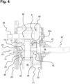
- the gear arrangement 40 is in particular Fig. 4 illustrated gear set 49 and a transmission input shaft 47.
- Rotation of the spindle 42 causes a spindle nut 31, which is firmly attached to an upper section 33 of the inner tube 30, to move either upwards or downwards, depending on the direction of rotation.
- the spindle nut 31 moves downwards, it pushes the inner tube 30 and the support foot 32 attached to it toward the ground, and the landing gear is extended.
- the spindle nut 31 moves upwards, it lifts the inner tube 30 and the support foot 32, and the landing gear is retracted.
- the spindle 42 passes through a spindle bearing plate 21 arranged below the gear 41, which is formed with a spindle opening 24 whose inner diameter is selected to be only slightly larger than the outer diameter of the spindle 42.
- the spindle 42 is mounted in its radial direction with the aid of the spindle bearing plate 21 and the spindle opening 24.
- the spindle bearing plate 21 is firmly connected to the inner wall of the outer tube 20 on at least three sides, preferably on four sides.
- the spindle bearing plate 21 is aligned essentially orthogonally to the extension of the outer tube 20.
- the spindle 42 and the associated spindle opening 24 in the spindle bearing plate 21 are accommodated centrally in the outer tube 20.
- An axial bearing 43 is pushed onto the spindle 42 beneath the spindle bearing plate 21, which in turn is adjacent to a spindle stop ring 46. As soon as the support foot 32 rests on the ground, the spindle stop ring 46 pushes the axial bearing 43 upward until it rests against an underside 23 of the spindle bearing plate 21.
- a recess 25, in particular a measuring dowel bore 25, is introduced, which is aligned transversely to the spindle 42 and which also extends through the outer tube 20 at its end facing away from the spindle 42.
- the recess 25 is in the same type of landing gear in Fig. 2 as a view onto the section plane CC according to Fig. 1 and in enlarged view in Fig. 3 This can be seen particularly clearly.
- the recess 25 is designed as a blind hole 26, the deepest part 27 of which is located in the spindle bearing plate 21 in close proximity to the spindle opening 24.
- the recess 25 runs parallel to the mounting flange plates 28 and is thus oriented in or against the direction of travel when the landing gear is mounted on a vehicle.
- a pin-shaped force measuring element 10, in particular in the form of a measuring dowel 11, is inserted in a stationary manner into the recess 25 and is clamped within the measuring dowel bore 25 relative to the spindle bearing plate 21.
- the position of the measuring dowel 11 shown as an example is in the area of the borehole deepest point 27 and thus in a projected area above the axial bearing 43.
- the spindle bearing plate 21 Since the spindle bearing plate 21 is force-locked to the outer tube 20 at its edge area, the relatively greatest deformation occurs in the area of the spindle bearing plate 21 above the axial bearing 43 and thus the most precise measurement of this deformation can be achieved by means of the measuring dowel 11, the measured value of which can be assigned to a corresponding support load.
- a transition coupling 13 is inserted into an open end of the measuring dowel bore 25, with the aid of which the measuring dowel bore 25 is closed to the outside and through which only a connecting cable 14 is led out of the measuring dowel bore 25.
- the measuring dowel 11 Via the connecting cable 14, the measuring dowel 11 is electrically connected to an on-board network of a vehicle (not shown here), from which the measuring dowel 11 is supplied with electrical power. Furthermore, the measuring dowel 11 provides the vehicle with force measurement signals via the connecting cable 14.
- Fig. 4 an alternative embodiment is shown in which the measuring dowel bore 25 is arranged offset by 90° in the spindle bearing plate 21 and the outer tube 20 and breaks through the outer tube 20 at the rear, between the mounting flange plates 28.
- the landing gear has a gear input shaft 47, to which a crank (not shown) can be connected in a rotationally fixed manner. Using the crank, an operator can rotate the gear input shaft 47, whereby the inner tube 30 with the support foot 32 can be extended or retracted as required, depending on the direction of rotation. In the illustration of the Fig. 4 the inner tube 30 is in a retracted position relative to the outer tube 20.
- the transmission input shaft 47 transmits the torque to the gear set 49, which meshes with the gear 41 of the transmission assembly 40 and also engages a transmission output shaft 48.
- the transmission input shaft 47 and the transmission output shaft 48 are aligned axially parallel to each other.
- the recess 25 or measuring dowel bore 25 also runs parallel to the transmission input shaft 47 and the transmission output shaft 48.
- the axial bearing 43 of the spindle 42 is constructed in two parts and comprises an upper bearing section 44, which is arranged adjacent to the underside 23 of the spindle bearing plate 21.
- an upper bearing section 44 which is arranged adjacent to the underside 23 of the spindle bearing plate 21.
- the measuring dowel bore 25, which runs radially towards the spindle 42, is aligned and dimensioned such that the measuring dowel 11 clamped therein is arranged above the axial bearing 43 and thus as close as possible to the force introduction point of the forces transmitted from the spindle 42 into the spindle bearing plate 21.
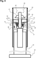
- the Fig. 5 represents an alternative embodiment with a force measuring element 10 in the form of a strain gauge application 12.
- the strain gauge application 12 is applied to the upper side 22 of the spindle bearing plate 21 and overlaps at least partially with the axial bearing 43 arranged underneath, via which a compressive force is transmitted in the direction of the arrow to the spindle bearing plate 21 when a support foot 32 rests on the ground.
- a large part of the deformation of the spindle bearing plate 21 takes place in an area of the strain gauge application 12, which enables particularly precise force measurement.
- the strain gauge application 12 can be connected to the energy and data system of a vehicle by means of a connecting cable 14.
- FIG. 6 A further embodiment is shown, in which a measuring plate 15 is inserted between the axial bearing 43 of the spindle 42 and the spindle bearing plate 21 fastened to the outer tube 20.
- the measuring plate 15 is provided with a central bore for receiving the spindle 42 and is designed with a closed ring shape.
- the measuring plate 15 experiences a compressive force from the spindle 42 moving upwards in the direction of the arrow, which presses the measuring plate 15 via the spindle stop ring 46 and the axial bearing 43 against the underside 23 of the spindle bearing plate 22.
- the spindle bearing plate 22 ensures a Power transmission to the outer tube 20 and from there via the mounting flange plate 28 (see Fig. 1 ) on the vehicle.
- the measuring plate 15 has a recess 25, in particular a measuring dowel bore 25, into which a pin-shaped force measuring element 10, in particular a measuring dowel 11, is inserted as the force measuring element 10.
- the recess 25 is aligned radially to the spindle 42, and the pin-shaped force measuring element 10, in particular the measuring dowel 11, is located above the axial bearing 43 of the spindle 42, which transmits the forces to the measuring plate 15 when the support winch is loaded.
- the measuring plate 15 is connected to the spindle bearing plate 21 in a rotationally fixed manner via a measuring plate holder 16. As a result, the measuring plate 15 is held in a rotationally fixed manner relative to the outer tube 20, and the connecting line 14 can be led out of the outer tube 20 at a predetermined position without having to install movable cables.
- the Fig. 7 shows a further embodiment with a measuring plate 15 provided with a strain gauge application 12.
- the measuring plate 15 is designed with a concave or bridge-like shape and, when loaded, is supported only in its lateral edge region by means of support sections 17 on the underside 23 of the spindle bearing plate 21.
- the self-supporting section 18 located between the support sections 17 is always arranged at a distance from the underside 23 of the spindle bearing plate 21, regardless of the load on the axial bearing 43, and carries the strain gauge application 12, which cannot collide with the spindle bearing plate 21 due to this installation location.
- the measuring plate 15 with the force measuring element 10 is also possible to design the measuring plate 15 with the force measuring element 10 as a particularly thin measuring foil.
- the Fig. 8 shows a further embodiment with a concave or bridge-like shape of the measuring plate 15, whose upstanding support sections 17 protrude in the direction of the spindle bearing plate 21 relative to the cantilevered section 18 arranged therebetween.
- a recess 25 tapering radially toward the spindle 42 is formed in the measuring plate 15, in particular a measuring dowel bore 25, into which a pin-shaped force measuring element 10, in particular a measuring dowel 25, is inserted.
- the force measuring element 10 is located in an area of the cantilevered section 18 of the measuring plate 15, which, when loaded by the support winch, is subject to greater, reversible deformation than the support sections 17 and enables particularly precise measurement.
- a pressure sensor 19 is used as the force measuring element 10, which is arranged on a side of the self-supporting section 18 facing the spindle bearing plate 21.
- the pressure sensor 19 terminates on its upper side with the support sections 17 of the measuring plate 15 and, when the landing gear is loaded, rests together with the support sections 17 on the underside 23 of the spindle bearing plate 21, so that a force shunt exists and the pressure sensor 19 is subjected to only a portion of the total force transmitted from the axial bearing 43 to the spindle bearing plate 21.
Landscapes
- Physics & Mathematics (AREA)
- General Physics & Mathematics (AREA)
- Engineering & Computer Science (AREA)
- Mechanical Engineering (AREA)
- Force Measurement Appropriate To Specific Purposes (AREA)
- Vehicle Cleaning, Maintenance, Repair, Refitting, And Outriggers (AREA)
Description
- Die Erfindung betrifft eine Stützwinde mit einem Kraftmesselement gemäß der im Oberbegriff des Anspruchs 1 stehenden Merkmale.
- Derartige Stützwinden sind häufig an Sattelaufliegern oder allgemein Anhängern angebracht und stützen diese insbesondere in einem vom Zugfahrzeug abgekuppelten Zustand auf dem Untergrund ab. Hierdurch behält der Sattelauflieger in seiner Parkposition eine stabile Lage und kann für ein erneutes Ankuppeln von einem Zugfahrzeug angefahren werden. In anderen Anwendungsfällen sind die Stützwinden am Heck von Silofahrzeugen angeordnet und werden vor dem Einleiten des Kippvorgangs ausgefahren, um das Fahrzeug zu stabilisieren.
EP-A-3293062 offenbart eine solche Stützwinde. - Aus der
DE 10 2005 036 139 A1 ist eine Stützwinde mit einem Druckelement und einem Stützlastindikator bekannt geworden, welches dem Bediener beim Ausfahren der Stützwinde einen sicheren Stand anzeigt. Das Druckelement umfasst ein Federelement und ein damit zusammenwirkendes Schaltelement in Form eines mechanischen Tasters, wobei das Federelement zwischen einem ortsfest an der Spindel angeordneten Spindelanschlagring und der Spindellagerplatte angeordnet ist. Während eines Ausfahrens der Stützwinde wandert bei einem tragfähigen Untergrund die Spindel gegen die Spindellagerplatte, so dass sich das Federelement verformt und das Schaltelement betätigt. Das Schaltelement wiederum steht mit einem Anzeigeelement in Verbindung, das dem Bediener das Vorliegen einer belasteten Stützwinde anzeigt. Es hat sich jedoch als nachteilig herausgestellt, dass das Federelement nach häufigen Belastungswechseln keine reproduzierbaren Werte liefert und mithin bereits bei einer zu geringen Krafteinleitung das Schaltelement auslöst. Überdies ist mit dem Stützlastindikator keine quantitative Aussage über die von der Stützwinde übertragenen Kräfte möglich. - Folglich lag der Erfindung die Aufgabe zugrunde, eine Stützwinde bereitzustellen, die eine quantitative und reproduzierbare Messung der von der Stützwinde auf den Untergrund übertragenen Kräfte ermöglicht.
- Die Aufgabe wird erfindungsgemäß mit den Merkmalen des Anspruchs 1 gelöst. Mit einem in dem Stützbauteil integrierten Kraftmesselement lässt sich feststellen, ob ein abzukuppelnder Anhänger sicher abgestellt ist und insbesondere bei einem Sattelauflieger die Stützwinden festen Bodenkontakt haben. Neben dieser qualitativen Feststellung erfolgt auch eine quantitative Feststellung der auf die Stützwinden wirkenden Last. Hierdurch ist es möglich, zusammen mit einer Erfassung der Achslasten auf das Gesamtgewicht des Anhängers zu schließen und hierdurch eine potentielle Überladung oder eine ungleichmäßige Ladungsverteilung zu ermitteln.
- Unter einem Kraftmesselement wird ein Sensor verstanden, der aus einer Verformung des Stützbauteils ein zu der eingeleiteten Kraft proportionales Signal erzeugt. Hierbei handelt es sich beispielsweise um piezoelektrisch arbeitende Sensoren, welche die Änderung der elektrischen Polarisation und somit das Auftreten einer elektrischen Spannung an Festkörpern erfassen, wenn diese elastisch verformt werden. Alternativ können kapazitive Sensoren als Kraftmesselement zum Einsatz kommen.
- Das Kraftmesselement ist an dem Stützbauteil angebracht, wobei hierbei eine Befestigung des Kraftmesselementes innerhalb des Stützbauteils oder auf der Oberfläche des Stützbauteils bevorzugt ist. Allen Befestigungspositionen ist gemein, dass das Kraftmesselement derart mit dem Stützbauteil verbunden ist, dass es dessen Verformung möglichst präzise erfasst, wobei eine kraft-, stoff- und/oder formschlüssige Verbindung geeignet ist, insbesondere durch passgenaues Klemmen oder eine Klebung.
- Günstigerweise ist unter der Spindellagerplatte ein Axiallager der Spindel angeordnet. Das Axiallager umgreift die Spindel und sorgt für eine drehbare Lagerung der Spindel bei gleichzeitiger Abstützung der auf Druck beanspruchten Spindel in axialer Richtung gegen die Spindellagerplatte. Eine radiale Lagerung der Spindel erfolgt hingegen durch die Spindelöffnung in der Spindellagerplatte.
- Gemäß einer besonders sinnvollen Ausgestaltung liegt das Axiallager zumindest in belastetem Zustand der Spindel mit seinem oberen Lagerabschnitt an der Unterseite des Stützbauteils an. Der obere Lagerabschnitt des Axiallagers ist hierdurch zumindest unter Last ortsfest zu dem Stützbauteil angeordnet.
- Gemäß einer ersten bevorzugten Ausführungsform ist das Stützbauteil die Spindellagerplatte. Alternativ hierzu kann das Stützbauteil auch eine zwischen dem oberen Lagerabschnitt des Axiallagers und der Spindellagerplatte angeordnete Messplatte sein. Die Messplatte ist beispielsweise als Messring ausgeformt, welcher die Spindel koaxial umgibt.
- Vorzugsweise ist die Messplatte bezüglich des Außenrohrs drehfest montiert. Hieraus resultiert der Vorteil, dass eine Anschlussleitung stationär verlegbar ist.
- Die Messplatte kann insbesondere eine konkave oder brückenartige Form mit außenliegenden, der Spindellagerplatte zugewandten Stützabschnitten und einem dazwischen angeordneten, freitragenden Abschnitt aufweisen. Aufgrund dieser Form ist im Bereich des freitragenden Abschnittes stets ein freier Bauraum zu der Spindellagerplatte vorhanden, in welchen beispielsweise besonders geschützt ein Kraftmesselement eingesetzt sein kann. Überdies sorgt die konkave oder brückenartige Form der Messplatte für eine größere Verformung der Messplatte im Bereich des freitragenden Abschnittes bei einer Krafteinleitung aus dem Axiallager, welches eine axial gerichtete Kraft mittig auf den freitragenden Abschnitt einleitet, wodurch eine verhältnismäßig große Verformung und dadurch bedingt eine genauere Kraftmessung möglich ist.
- Das Axiallager kann insbesondere mit seinem unteren Lagerabschnitt an einem fest mit der Spindel verbundenen Spindelanschlagring anliegen. Der untere Lagerabschnitt ist somit drehbeweglich zu dem Stützbauteil und ortsfest zur Spindel angeordnet. Bei belasteter Spindel drückt das Stützbauteil von unten gegen den unteren Lagerabschnitt und schiebt das Axiallager mit dem oberen Lagerabschnitt gegen das Stützbauteil, welches sich infolge der eingeleiteten Last deformiert.
- Sinnvollerweise ist das Kraftmesselement über dem Axiallager zumindest teilweise in dessen projizierter Fläche angeordnet. In diesem Bereich wird die Last über das Axiallager in das Stützbauteil eingeleitet und die vom Kraftmesselement messbare Verformung ist am Größten, wodurch eine besonders exakte und reproduzierbare Bestimmung der eingeleiteten Kraft möglich ist.
- Zweckmäßigerweise ist das Kraftmesselement gemäß einer weiteren Ausgestaltung der Erfindung stiftförmig ausgebildet und in eine komplementär ausgeformte Ausnehmung des Stützbauteils spielfrei oder unter Vorspannung eingesetzt.
- Besonders zweckmäßig ist eine Ausführungsform, bei welcher das stiftförmig ausgebildete Kraftmesselement ein Messdübel ist. Unter einem Messdübel wird ein in Querrichtung kraftempfindlicher Sensor verstanden, der typischerweise mit einer zylindrischen Form ausgebildet und in eine komplementär ausgeformte Messdübelbohrung in dem zu messenden Bauteil stets oder zumindest bei Vorliegen der zu erwartenden Betriebslast passgenau und/oder unter Vorspannung eingesetzt ist. Die Vorspannung des Messdübels wird beispielsweise mittels einer in den Messdübel integrierten Klemmvorrichtung realisiert.
- Vorzugsweise ist die Ausnehmung eine in dem Stützbauteil ausgebildete Messdübelbohrung, in welche der Messdübel eingesetzt ist. Der Durchmesser der Messdübelbohrung beträgt typischerweise 6,00 mm bis 10,00 mm, besonders bevorzugt 8 mm.
- Die Messdübelbohrung kann in dem Stützbauteil beispielsweise radial zu der Spindel ausgerichtet sein. Bevorzugt ist die Messdübelbohrung außerdem orthogonal zu einer benachbarten Wandung des Außenrohres angeordnet, wodurch die Länge der Messdübelbohrung und damit die Materialschwächung des Stützbauteils möglichst gering ist.
- Günstigerweise überstreicht die Messdübelbohrung in axialer Richtung versetzt das Axiallager zumindest teilweise. Hierdurch ist es möglich, den Messdübel über dem Axiallager in einem Bereich der maximalen Krafteinleitung zu platzieren.
- Zweckmäßigerweise ist die Messdübelbohrung als Sackloch ausgeformt und der Messdübel in das Bohrlochtiefste des Sacklochs eingesetzt. Hieraus resultiert eine besonders geschützte Montageposition des Messdübels.
- Gemäß einer weiteren, alternativen Ausführungsform ist das Kraftmesselement eine Dehnungs-Mess-Streifen-Applikation. Die Dehnungs-Messstreifen-Applikation dient zur Erfassung von dehnenden und stauchenden Verformungen des Stützbauteils. Sie ändert schon bei geringen Verformungen ihren elektrischen Widerstand und wird als Dehnungssensor eingesetzt. Typischerweise ist die Dehnungs-Messstreifen-Applikation auf das sich unter Belastung minimal verformende Stützbauteil geklebt. Dessen Verformung (Dehnung) unter Last führt dann zur Veränderung des elektrischen Widerstands der Dehnungs-Messstreifen-Applikation.
- Bevorzugt ist eine Anbringung der Dehnungs-Mess-Streifen-Applikation auf einer Ober- und/oder Unterseite des Stützbauteils. Hieraus resultiert einerseits der Vorteil, dass keine Schwächung des Stützbauteils durch Bohrungen oder Ausfräsungen vorzunehmen sind und andererseits, dass auf der Oberseite und Unterseite des Stützbauteils eine maximale Dehnung oder Stauchung vorliegt und dadurch besonders exakte und reproduzierbare Messwerte erzielbar sind.
- Vorteilhafterweise ist das Kraftmesselement ein zwischen der Messplatte und der Spindellagerplatte angeordneter Drucksensor. Ein Drucksensor gehört zur Gruppe der Druckmessgeräte, welche als erstes Glied einer Messkette die physikalische Größe Druck (Kraft pro Fläche) in eine elektrische Ausgangsgröße als Maß für den Druck umformen. Geeignet ist insbesondere ein piezoresistiv oder piezoelektrisch, kapazitiv oder induktiv arbeitender Drucksensor sowie ein Drucksensor mit Hallelement.
- Eine besonders sinnvolle Ausgestaltung der Erfindung kann vorsehen, dass der Drucksensor derart an dem freitragenden Abschnitt der konkav oder brückenartig geformten Messplatte angeordnet ist, dass ein Kraftnebenschluss über den Drucksensor auf die Spindellagerplatte erfolgt. Hieraus resultiert der Vorteil, dass der Drucksensor nicht den gesamten Kraftfluss der Stützwinde übertragen muss und dadurch weitgehend vor einer Überlastung geschützt ist. Auch ist das Spektrum der zu übertragenden Kräfte geringen, so dass ein Drucksensor mit einem geringer gespreizten Messbereich verwendet werden kann, welcher wiederum präzisere Messwerte bereitstellt.
- Zum besseren Verständnis wird die Erfindung nachfolgend anhand von neun Figuren näher erläutert. Es zeigen die
- Fig. 1:
- einen Längsschnitt durch eine Stützwinde gemäß einer ersten Ausführungsform mit einem stiftförmig ausgebildeten Kraftmesselement in einer Spindellagerplatte;
- Fig. 2:
- einen Querschnitt durch die Stützwinde gemäß
Fig. 1 in der Schnittebene C-C; - Fig. 3:
- einen vergrößerten Ausschnitt des Details X in
Fig. 2 ; - Fig. 4:
- einen Längsschnitt durch den oberen Abschnitt einer Stützwinde gemäß einer zweiten Ausführungsform mit einem stiftförmig ausgebildeten Kraftmesselement in der Spindellagerplatte;
- Fig. 5:
- einen Längsschnitt durch eine schematisch dargestellte Stützwinde mit einer Dehnungs-Messstreifen-Applikation als Kraftmesselement auf der Spindellagerplatte;
- Fig. 6:
- einen Längsschnitt durch eine schematisch dargestellte Stützwinde mit einem stiftförmig ausgebildeten Kraftmesselement in einer Messplatte;
- Fig. 7:
- einen Längsschnitt durch eine schematisch dargestellte Stützwinde mit einer Dehnungs-Messstreifen-Applikation als Kraftmesselement auf einer Messplatte;
- Fig. 8:
- einen Längsschnitt durch eine schematisch dargestellte Stützwinde mit einer konkaven oder brückenartigen Messplatte und einem darin eingesetzten Kraftmesselement und
- Fig. 9:
- einen Längsschnitt durch eine schematisch dargestellte Stützwinde mit einer konkaven oder brückenartigen Messplatte und einem zwischen freitragendem Abschnitt und Spindellagerplatte angeordneten Drucksensor.
- Die
Fig. 1 zeigt einen Längsschnitt einer Stützwinde mit einem Außenrohr 20 in Form eines Vierkantprofils und einem axial darin geführten Innenrohr 30. Aufgrund der komplementären Profilform von Außen- und Innenrohr 20, 30 ist das Innenrohr 30 in Umfangsrichtung drehfest in dem Außenrohr 20 gehalten. - Für eine Befestigung der Stützwinde an einem Fahrzeug ragt beidseitig des Außenrohrs 20 eine Montageflanschplatte 28 hervor, in welcher in diskreten Abständen Montagelöcher 29 eingebracht sind. Das Innenrohr 30 trägt an seinem unteren Ende einen Stützfuß 32, mit welchem die Stützwinde bei ausgefahrenem Innenrohr 30 auf dem Untergrund aufsteht.
- In dem Außenrohr 20 ist eine Getriebeanordnung 40 mit einer gegenüber dem Außenrohr 20 drehbar gelagerten Spindel 42 und einem Zahnrad 41 angeordnet, welches an einem oberen Endabschnitt der Spindel 42 drehfest mit dieser verbunden ist. Die Getriebeanordnung 40 ist insbesondere von einem in
Fig. 4 dargestellten Zahnradsatz 49 und einer Getriebeeingangswelle 47 in Drehung versetzt. Durch eine Drehung der Spindel 42 wandert eine an einem oberen Abschnitt 33 des Innenrohrs 30 fest eingesetzte Spindelmutter 31 je nach Drehsinn entweder nach unten oder nach oben. Bei einer Bewegung der Spindelmutter 31 nach unten, drückt sie das Innenrohr 30 nebst daran befestigtem Stützfuß 32 in Richtung Untergrund und die Stützwinde wird ausgefahren. Bei einer Bewegung der Spindelmutter 31 nach oben, hebt sie das Innenrohr 30 nebst Stützfuß 32 an und die Stützwinde wird eingefahren. - Die Spindel 42 durchläuft eine unter dem Zahnrad 41 angeordnete Spindellagerplatte 21, welche mit einer Spindelöffnung 24 ausgebildet ist, deren Innendurchmesser nur geringfügig größer als der Außendurchmesser der Spindel 42 gewählt ist. Mit Hilfe der Spindellagerplatte 21 und der Spindelöffnung 24 ist die Spindel 42 in ihrer radialen Richtung gelagert. Die Spindellagerplatte 21 ist mindestens an drei Seiten, bevorzugt an vier Seiten, fest mit der Innenwand des Außenrohrs 20 verbunden. Die Spindellagerplatte 21 ist im Wesentlichen orthogonal zu der Erstreckung des Außenrohrs 20 ausgerichtet. Die Spindel 42 und die zugehörige Spindelöffnung 24 in der Spindellagerplatte 21 sind mittig in dem Außenrohr 20 untergebracht.
- Unter der Spindellagerplatte 21 ist auf die Spindel 42 ein Axiallager 43 aufgeschoben, welches wiederum an einen Spindelanschlagring 46 angrenzt. Sobald der Stützfuß 32 auf dem Untergrund aufsteht, drückt der Spindelanschlagring 46 das Axiallager 43 nach oben, bis dieses an einer Unterseite 23 der Spindellagerplatte 21 zur Anlage gelangt.
- In der Spindellagerplatte 21 ist eine quer zur Spindel 42 ausgerichtete Ausnehmung 25, insbesondere eine Messdübelbohrung 25, eingebracht, die sich an ihrem der Spindel 42 abgewandten Ende auch durch das Außenrohr 20 erstreckt. Die Ausnehmung 25 ist bei demselben Stützwindentyp in
Fig. 2 als Ansicht auf die Schnittebene C-C gemäßFig. 1 und in vergrößerter Darstellung inFig. 3 besonders gut zu erkennen. In dem Ausführungsbeispiel ist die Ausnehmung 25 als Sackloch 26 ausgebildet, dessen Bohrlochtiefstes 27 in der Spindellagerplatte 21 unmittelbar in räumlicher Nähe zu der Spindelöffnung 24 angeordnet ist. Die Ausnehmung 25 verläuft in diesem Ausführungsbeispiel parallel zu den Montageflanschplatten 28 und ist somit bei einer an einem Fahrzeug montierten Stützwinde in beziehungsweise entgegen der Fahrtrichtung ausgerichtet. - In die Ausnehmung 25 ist ortsfest ein stiftförmig ausgebildetes Kraftmesselement 10, insbesondere in Form eines Messdübels 11, eingesetzt und innerhalb der Messdübelbohrung 25 gegenüber der Spindellagerplatte 21 verspannt. Die Lage des beispielhaft dargestellten Messdübels 11 befindet sich im Bereich des Bohrlochtiefsten 27 und somit in einer projizierten Fläche über dem Axiallager 43. Bei gegenüber dem Außenrohr 20 ausgefahrenem Innenrohr 30 und auf dem Untergrund aufstehendem Stützfuß 32 erfolgt ein Kraftfluss von dem Stützfuß 32 über das Innenrohr 30, die Spindelmutter 31, die Spindel 42 und das Axiallager 43 in die Spindellagerplatte 21. Da die Spindellagerplatte 21 an ihrem Randbereich mit dem Außenrohr 20 kraftschlüssig verbunden ist, kommt es in dem Bereich der Spindellagerplatte 21 über dem Axiallager 43 zu der verhältnismäßig größten Verformung und damit zu einer möglichst präzisen Messung dieser Verformung mittels des Messdübels 11, dessen Messwert einer entsprechenden Stützlast zuordbar ist.
- Die innerhalb der Spindellagerplatte 21 beispielhaft angeordnete Messdübelbohrung 25 setzt sich in fluchtender Erstreckung auch in dem Außenrohr 20 fort. In ein offenes Ende der Messdübelbohrung 25 ist eine Übergangskupplung 13 eingesetzt, mit deren Hilfe die Messdübelbohrung 25 nach außen verschlossen ist und durch welche lediglich eine Anschlussleitung 14 aus der Messdübelbohrung 25 herausgeführt ist. Über die Anschlussleitung 14 ist der Messdübel 11 elektrisch an ein Bordnetzwerk eines hier nicht gezeigten Fahrzeugs angeschlossen, aus welchem der Messdübel 11 mit elektrischer Energie versorgt ist. Überdies stellt der Messdübel 11 Messsignale der Kraftmessung über die Anschlussleitung 14 dem Fahrzeug zur Verfügung.
- In
Fig. 4 ist ein alternatives Ausführungsbeispiel gezeigt, bei welchem die Messdübelbohrung 25 um 90° versetzt in der Spindellagerplatte 21 und dem Außenrohr 20 angeordnet ist und rückseitig, zwischen den Montageflanschplatten 28 das Außenrohr 20 durchbricht. - Für ein Aus- oder Einfahren weist die Stützwinde die Getriebeeingangswelle 47 auf, mit welcher insbesondere eine nicht gezeigte Kurbel drehfest verbindbar ist. Mit Hilfe der Kurbel kann eine Bedienperson die Getriebeeingangswelle 47 in Drehung versetzen, wodurch das Innenrohr 30 mit dem Stützfuß 32 je nach Drehsinn wahlweise aus- oder einfährt. In der Darstellung der
Fig. 4 befindet sich das Innenrohr 30 in einer bezüglich des Außenrohrs 20 eingefahrenen Position. - Die Getriebeeingangswelle 47 überträgt das Drehmoment auf den Zahnradsatz 49, welcher das Zahnrad 41 der Getriebeanordnung 40 kämmt und außerdem an einer Getriebeausgangswelle 48 angreift. Die Getriebeeingangswelle 47 und die Getriebeausgangswelle 48 sind achsparallel zueinander ausgerichtet. Ebenfalls parallel zu der Getriebeeingangswelle 47 und der Getriebeausgangswelle 48 verläuft die Ausnehmung 25 beziehungsweise Messdübelbohrung 25.
- Das Axiallager 43 der Spindel 42 ist zweiteilig aufgebaut und umfasst einen oberen Lagerabschnitt 44, der benachbart zu der Unterseite 23 der Spindellagerplatte 21 angeordnet ist. Bei einem in das Außenrohr 20 eingefahrenen Innenrohr 30 kann aufgrund des Eigengewichts von Innenrohr 30 und Stützfuß 32 zwischen dem oberen Lagerabschnitt 44 und der Unterseite 23 der Spindellagerplatte 21 ein Spalt ausgebildet sein, da in dieser eingefahrenen Position die Spindel 42 mittels ihres Sicherungsbolzens 42a hängend an einer Oberseite 22 der Spindellagerplatte 21 abgestützt ist.
- Bei ausgefahrenem Innenrohr 30 und einem auf dem Untergrund aufstehenden Stützfuß 32 wird die Spindel 42 nach oben gedrückt und der ortsfest an der Spindel 42 angeformte Spindelanschlagring 46 stößt gegen einen unteren Lagerabschnitt 45 des Axiallagers 43. Mit Hilfe des Axiallagers 43 erfolgt eine Kraftübertragung auf den oberen Lagerabschnitt 44, welcher gegen die Unterseite 23 der Spindellagerplatte 21 gedrückt ist und an dieser anliegt. Gleichzeitig lässt das Axiallager 43 auch bei einer Druckbelastung der Stützwinde eine weitere Rotation der Spindel 42 zu.
- Die radial auf die Spindel 42 zulaufende Messdübelbohrung 25 ist derart ausgerichtet und dimensioniert, dass der darin verspannte Messdübel 11 über dem Axiallager 43 und somit möglichst nah am Krafteinleitungspunkt der von der Spindel 42 in die Spindellagerplatte 21 übertragenen Kräfte angeordnet ist.
- Die
Fig. 5 stellt eine alternative Ausführungsform mit einem Kraftmesselement 10 in Form einer Dehnungs-Messstreifen-Applikation 12 dar. Die Dehnungs-Messstreifen-Applikation 12 ist auf der Oberseite 22 der Spindellagerplatte 21 aufgebracht und überlappt zumindest teilweise mit dem darunter angeordneten Axiallager 43, über das bei einem auf dem Untergrund aufstehenden Stützfuß 32 eine Druckkraft in Pfeilrichtung auf die Spindellagerplatte 21 übertragen wird. Hierdurch findet ein Großteil der Verformung der Spindellagerplatte 21 in einem Bereich der Dehnungs-Messstreifen-Applikation 12 statt, wodurch eine besonders präzise Kraftmessung möglich ist. - Die Dehnungs-Messstreifen-Applikation 12 ist mittels einer Anschlussleitung 14 an das Energie- und Datensystem eines Fahrzeugs anschließbar.
- In der
Fig. 6 ist ein weiteres Ausführungsbeispiel dargestellt, bei dem zwischen dem Axiallager 43 der Spindel 42 und der am Außenrohr 20 befestigten Spindellagerplatte 21 eine Messplatte 15 eingesetzt ist. Die Messplatte 15 ist mit einer zentrischen Bohrung zur Aufnahme der Spindel 42 versehen und mit einer geschlossenen Ringform ausgebildet. Bei einer ausgefahrenen und belasteten Stützwinde erfährt die Messplatte 15 eine Stauchkraft aus der nach oben in Pfeilrichtung wandernden Spindel 42, welche die Messplatte 15 über den Spindelanschlagring 46 und das Axiallager 43 gegen die Unterseite 23 der Spindellagerplatte 22 drückt. Die Spindellagerplatte 22 sorgt für eine Kraftübertragung auf das Außenrohr 20 und von dort über die Montageflanschplatte 28 (sieheFig. 1 ) auf das Fahrzeug. - Die Messplatte 15 weist eine Ausnehmung 25 auf, insbesondere eine Messdübelbohrung 25, in welche als Kraftmesselement 10 ein stiftförmig ausgebildetes Kraftmesselement 10, insbesondere ein Messdübel 11, eingesetzt ist. Die Ausnehmung 25 ist radial zu der Spindel 42 ausgerichtet und das stiftförmig ausgebildete Kraftmesselement 10, insbesondere der Messdübel 11, befindet sich über dem Axiallager 43 der Spindel 42, welches im belasteten Zustand der Stützwinde die Kräfte in die Messplatte 15 überträgt.
- Um ein Mitdrehen der Messplatte 15 zusammen mit der Spindel 42 zu verhindern, ist die Messplatte 15 über einen Messplattenhalter 16 drehfest an die Spindellagerplatte 21 angeschlossen. Hierdurch ist die Messplatte 15 drehfest zu dem Außenrohr 20 gehalten und die Anschlussleitung 14 kann an einer vorgegebenen Position aus dem Außenrohr 20 herauszuführt sein, ohne bewegliche Kabel verlegen zu müssen.
- Die
Fig. 7 zeigt ein weiteres Ausführungsbeispiel mit einer Messplatte 15, die mit einer Dehnungs-Messstreifen-Applikation 12 versehen ist. Die Messplatte 15 ist mit einer konkaven oder brückenartigen Form ausgebildet und stützt sich im Belastungsfall lediglich in ihren seitlichem Randbereich mittels Stützabschnitte 17 an der Unterseite 23 der Spindellagerplatte 21 ab. Der sich zwischen den Stützabschnitten 17 befindliche freitragende Abschnitt 18 ist unabhängig von der Belastung des Axiallagers 43 stets beabstandet zu der Unterseite 23 der Spindellagerplatte 21 angeordnet und trägt die Dehnungs-Messstreifen-Applikation 12, welche aufgrund dieses Einbauortes nicht mit der Spindellagerplatte 21 kollidieren kann. - Es ist ebenso möglich, die Messplatte 15 mit dem Kraftmesselement 10 als besonders dünn konfigurierte Messfolie auszubilden. Auch hier befindet sich die Messplatte 15 im Kraftfluss zwischen dem Axiallager 43 und dem Außenrohr 20, um dort etwaige Kräfte messen zu können.
- Die
Fig. 8 zeigt ein weiteres Ausführungsbeispiel mit einer konkaven oder brückenartigen Form der Messplatte 15, deren aufstrebende Stützabschnitte 17 in Richtung der Spindellagerplatte 21 gegenüber dem dazwischen angeordneten, freitragenden Abschnitt 18 vorstehen. In der Messplatte 15 ist eine radial auf die Spindel 42 zulaufende Ausnehmung 25 ausgeformt, insbesondere eine Messdübelbohrung 25, in welche ein stiftförmig ausgebildetes Kraftmesselement 10, insbesondere ein Messdübel 25, eingesetzt ist. Das Kraftmesselement 10 befindet sich in einem Bereich des freitragenden Abschnittes 18 der Messplatte 15, welcher bei Belastung der Stützwinde einer im Vergleich zu den Stützabschnitten 17 größeren, reversiblen Verformung unterliegt und eine besonders genaue Messung ermöglicht. - In der
Fig. 9 ist eine erfindungsgemäße Stützwinde gemäß einer alternativen Ausgestaltung mit einer ebenfalls konkaven oder brückenartigen Messplatte 15 dargestellt. Als Kraftmesselement 10 kommt jedoch ein Drucksensor 19 zum Einsatz, welcher auf einer der Spindellagerplatte 21 zugewandten Seite des freitragenden Abschnittes 18 angeordnet ist. Der Drucksensor 19 schließt auf seiner Oberseite mit den Stützabschnitten 17 der Messplatte 15 ab und liegt bei Belastung der Stützwinde zusammen mit den Stützabschnitten 17 an der Unterseite 23 der Spindellagerplatte 21 an, so dass ein Kraftnebenschluss vorliegt und der Drucksensor 19 mit nur einem Teil der insgesamt von dem Axiallager 43 auf die Spindellagerplatte 21 übertragenen Kraft beaufschlagt ist. -
- 10
- Kraftmesselement
- 11
- stiftförmiges Kraftmesselement, Messdübel
- 12
- Dehnungs-Messstreifen-Applikation
- 13
- Übergangskupplung
- 14
- Anschlussleitung
- 15
- Messplatte
- 16
- Messplattenhalter
- 17
- Stützabschnitt(e) Messplatte
- 18
- freitragender Abschnitt Messplatte
- 19
- Drucksensor
- 20
- Außenrohr
- 21
- Spindellagerplatte
- 22
- Oberseite Spindellagerplatte
- 23
- Unterseite Spindellagerplatte
- 24
- Spindelöffnung Spindellagerplatte
- 25
- Ausnehmung, Messdübelbohrung
- 26
- Sackloch
- 27
- Bohrlochtiefste Sackloch
- 28
- Montageflanschplatte
- 29
- Montagelöcher
- 30
- Innenrohr
- 31
- Spindelmutter
- 32
- Stützfuß
- 33
- oberer Abschnitt Innenrohr
- 40
- Getriebeanordnung
- 41
- Zahnrad
- 42
- Spindel
- 42a
- Sicherungsbolzen
- 43
- Axiallager Spindel
- 44
- oberer Lagerabschnitt
- 45
- unterer Lagerabschnitt
- 46
- Spindelanschlagring
- 47
- Getriebeeingangswelle
- 48
- Getriebeausgangswelle
- 49
- Zahnradsatz
Claims (19)
- Stützwinde mit einem Kraftmesselement (10), wobei die Stützwinde ein Außenrohr (20), ein darin verschiebbar gelagertes Innenrohr (30) und eine Getriebeanordnung (40) aufweist, welche mindestens eine von einem Zahnrad (41) angetriebene Spindel (42) umfasst, die durch eine Spindelöffnung (24) einer am Außenrohr (20) angreifenden Spindellagerplatte (21) hindurchgeführt und auf der eine an dem Innenrohr (30) befestigte Spindelmutter (31) gehalten ist,
dadurch gekennzeichnet,
dass das Kraftmesselement (10) an einem im Kraftfluss zwischen Spindel (42) und Außenrohr (20) angeordneten Stützbauteil (15, 21) angebracht ist. - Stützwinde nach Anspruch 1, dadurch gekennzeichnet, dass mittels des Kraftmesselementes (10) eine Kraft in Abhängigkeit von der Verformung des Stützbauteils (15, 21) erfasst ist.
- Stützwinde nach Anspruch 1 oder 2, dadurch gekennzeichnet, dass unter der Spindellagerplatte (21) ein Axiallager (43) der Spindel (42) angeordnet ist.
- Stützwinde nach Anspruch 3, dadurch gekennzeichnet, dass das Axiallager (43) unter Last mit seinem oberen Lagerabschnitt (44) an der Unterseite (23) des Stützbauteils (15, 21) abgestützt ist.
- Stützwinde nach einem der Ansprüche 1 bis 4, dadurch gekennzeichnet, dass das Stützbauteil (15, 21) die Spindellagerplatte (21) ist.
- Stützwinde nach Anspruch 4, dadurch gekennzeichnet, dass das Stützbauteil (15, 21) eine zwischen dem oberen Lagerabschnitt (44) des Axiallagers (43) und der Spindellagerplatte (21) angeordnete Messplatte (15) ist.
- Stützwinde nach Anspruch 6, dadurch gekennzeichnet, dass die Messplatte (15) bezüglich des Außenrohrs (20) drehfest montiert ist.
- Stützwinde nach Anspruch 6 oder 7, dadurch gekennzeichnet, dass die Messplatte (15) eine konkave oder brückenartige Form mit außenliegenden, der Spindellagerplatte (21) zugewandten Stützabschnitten (17) und einem dazwischen angeordneten, freitragenden Abschnitt (18) aufweist.
- Stützwinde nach einem der Ansprüche 3 bis 8, dadurch gekennzeichnet, dass das Axiallager (43) mit seinem unteren Lagerabschnitt (45) an einem fest mit der Spindel (42) verbundenen Spindelanschlagring (46) anliegt.
- Stützwinde nach einem der Ansprüche 3 bis 9, dadurch gekennzeichnet, dass das Kraftmesselement (10) über dem Axiallager (43) zumindest teilweise in dessen projizierter Fläche angeordnet ist.
- Stützwinde nach einem der Ansprüche 1 bis 10, dadurch gekennzeichnet, dass das Kraftmesselement (10) stiftförmig ausgebildet und in eine komplementär ausgeformte Ausnehmung (25) des Stützbauteils (15, 21) spielfrei oder unter Vorspannung eingesetzt ist.
- Stützwinde nach Anspruch 11, dadurch gekennzeichnet, dass das stiftförmig ausgebildete Kraftmesselement (10) ein Messdübel (11) ist.
- Stützwinde nach Anspruch 11 und 12, dadurch gekennzeichnet, dass die Ausnehmung (25) eine in dem Stützbauteil (15, 21) ausgebildete Messdübelbohrung (25) ist, in welche der Messdübel (11) eingesetzt ist.
- Stützwinde nach Anspruch 13, dadurch gekennzeichnet, dass der Messdübel (11) in der Messdübelbohrung (25) mechanisch verspannt ist.
- Stützwinde nach Anspruch 13 oder 14, dadurch gekennzeichnet, dass die Messdübelbohrung (25) radial zu der Spindel (42) ausgerichtet ist.
- Stützwinde nach einem der Ansprüche 1 bis 10, dadurch gekennzeichnet, dass das Kraftmesselement (10) eine Dehnungs-Mess-Streifen-Applikation (12) ist.
- Stützwinde nach Anspruch 16, dadurch gekennzeichnet, dass die Dehnungs-Mess-Streifen-Applikation (12) auf einer Ober- und/oder Unterseite (22, 23) des Stützbauteils (15, 21) aufgebracht ist.
- Stützwinde nach einem der Ansprüche 6 bis 8, dadurch gekennzeichnet, dass das Kraftmesselement (10) ein zwischen der Messplatte (15) und der Spindellagerplatte (21) angeordneter Drucksensor (19) ist.
- Stützwinde nach Anspruch 18 soweit auf Anspruch 8 bezogen, dadurch gekennzeichnet, dass der Drucksensor (19) derart an dem freitragenden Abschnitt (18) der Messplatte (15) angeordnet ist, dass ein Kraftnebenschluss über den Drucksensor (19) auf die Spindellagerplatte (21) erfolgt.
Applications Claiming Priority (2)
| Application Number | Priority Date | Filing Date | Title |
|---|---|---|---|
| DE102021001553.3A DE102021001553B3 (de) | 2021-03-25 | 2021-03-25 | Stützwinde mit einem Kraftmesselement |
| PCT/IB2022/052774 WO2022201128A1 (de) | 2021-03-25 | 2022-03-25 | Stützwinde mit einem kraftmesselement |
Publications (2)
| Publication Number | Publication Date |
|---|---|
| EP4313701A1 EP4313701A1 (de) | 2024-02-07 |
| EP4313701B1 true EP4313701B1 (de) | 2025-05-21 |
Family
ID=81384752
Family Applications (1)
| Application Number | Title | Priority Date | Filing Date |
|---|---|---|---|
| EP22718293.8A Active EP4313701B1 (de) | 2021-03-25 | 2022-03-25 | Stützwinde mit einem kraftmesselement |
Country Status (8)
| Country | Link |
|---|---|
| US (1) | US11988567B2 (de) |
| EP (1) | EP4313701B1 (de) |
| JP (1) | JP7631550B2 (de) |
| CN (1) | CN117136154A (de) |
| BR (1) | BR112023019104A2 (de) |
| DE (1) | DE102021001553B3 (de) |
| PL (1) | PL4313701T3 (de) |
| WO (1) | WO2022201128A1 (de) |
Families Citing this family (1)
| Publication number | Priority date | Publication date | Assignee | Title |
|---|---|---|---|---|
| DE102021001552A1 (de) * | 2021-03-25 | 2022-09-29 | Jost-Werke Deutschland Gmbh | Stützwinde mit einem Stützfuß und einem Kraftmesselement |
Family Cites Families (12)
| Publication number | Priority date | Publication date | Assignee | Title |
|---|---|---|---|---|
| JPS5842202Y2 (ja) * | 1977-02-15 | 1983-09-24 | 各和精機株式会社 | 昇降脚における自動停止装置 |
| US4552324A (en) * | 1983-05-31 | 1985-11-12 | Pneumo Corporation | Landing gear mechanism for use on rough runways |
| JPH08268015A (ja) * | 1995-03-28 | 1996-10-15 | Nissan Diesel Motor Co Ltd | トレーラの脱着誤動作防止装置 |
| DE10205286C1 (de) * | 2002-02-05 | 2003-09-18 | Jost Werke Gmbh & Co Kg | Stützwinde |
| DE10349234A1 (de) * | 2003-10-20 | 2005-05-19 | Putzmeister Ag | Mobiles Arbeitsgerät mit Stützauslegern |
| DE102005036139B4 (de) | 2005-07-27 | 2008-11-13 | Jost-Werke Gmbh | Stützwinde mit Stützlastindikator |
| DE102008058937A1 (de) | 2008-05-21 | 2009-11-26 | Putzmeister Concrete Pumps Gmbh | Mobiles Arbeitsgerät mit Standsicherheitsüberwachung |
| DE202014000337U1 (de) * | 2014-01-17 | 2014-02-24 | Tecsis (Shenzhen) Sensors Co., Ltd. | Meßsystem zur Ermittlung von Stützkräften mit Funkschnittstelle |
| DE102015117086A1 (de) | 2015-10-07 | 2017-04-13 | Schwing Gmbh | Abstützvorrichtung zum Abstützen einer mobilen Vorrichtung |
| IT201600092134A1 (it) * | 2016-09-13 | 2018-03-13 | Simol S P A | Piede d'appoggio |
| DE102018122244B3 (de) * | 2018-09-12 | 2020-02-06 | Saf-Holland Gmbh | Stützeinheit und Verfahren zur Überwachung einer Stützeinheit |
| DE102019103905B4 (de) | 2019-02-15 | 2023-05-04 | Sensor-Technik Wiedemann Gmbh | Mechanisches Bauteil mit einer Kraftmesseinrichtung und Verfahren zum Messen einer Kraft |
-
2021
- 2021-03-25 DE DE102021001553.3A patent/DE102021001553B3/de active Active
-
2022
- 2022-03-25 US US18/551,902 patent/US11988567B2/en active Active
- 2022-03-25 PL PL22718293.8T patent/PL4313701T3/pl unknown
- 2022-03-25 EP EP22718293.8A patent/EP4313701B1/de active Active
- 2022-03-25 WO PCT/IB2022/052774 patent/WO2022201128A1/de not_active Ceased
- 2022-03-25 CN CN202280023180.8A patent/CN117136154A/zh active Pending
- 2022-03-25 JP JP2023558538A patent/JP7631550B2/ja active Active
- 2022-03-25 BR BR112023019104A patent/BR112023019104A2/pt unknown
Also Published As
| Publication number | Publication date |
|---|---|
| CN117136154A (zh) | 2023-11-28 |
| US11988567B2 (en) | 2024-05-21 |
| WO2022201128A1 (de) | 2022-09-29 |
| EP4313701A1 (de) | 2024-02-07 |
| US20240102872A1 (en) | 2024-03-28 |
| DE102021001553B3 (de) | 2022-08-18 |
| BR112023019104A2 (pt) | 2023-10-24 |
| JP7631550B2 (ja) | 2025-02-18 |
| JP2024512571A (ja) | 2024-03-19 |
| PL4313701T3 (pl) | 2025-09-01 |
Similar Documents
| Publication | Publication Date | Title |
|---|---|---|
| EP2981796B1 (de) | Kraft-messvorrichtung | |
| EP3084379B1 (de) | Kraftsensor für handbetriebene oder pneumatische pressen | |
| WO2009118350A2 (de) | Vorrichtung zur überwachung der bremswirkung | |
| EP4313702B1 (de) | Stützwinde mit einem stützfuss und einem kraftmesselement | |
| EP3820649B1 (de) | Drehmomentschrauberanordnung und verfahren zum betrieb einer solchen drehmomentschrauberanordnung | |
| DE102016104592A1 (de) | Stützenbauteil mit integriertem Kraftsensor | |
| DE102009002188A1 (de) | Kraftaufnehmer zur Messung von Stützkräften in einem Abstützelement | |
| EP2391874B1 (de) | Flurförderzeug | |
| WO2016180554A1 (de) | Verfahren zur bestimmung einer in ein bauteil eingebrachten axialen zugkraft | |
| WO2010057634A1 (de) | Kraftaufnehmer für stützelemente | |
| WO2002064990A1 (de) | Elektromechanische bremszuspanneinrichtung | |
| EP4313701A1 (de) | Stützwinde mit einem kraftmesselement | |
| EP0686839A2 (de) | Anhängerkupplung mit einem Kraftaufnehmer | |
| WO2020114543A1 (de) | Radnabe-lagereinheit eines fahrzeugs, insbesondere eines landwirtschaftlichen fahrzeugs, mit mitteln zur erfassung einer kraft | |
| WO2017020904A1 (de) | Dreipunktaufhängung | |
| DE102004033925B4 (de) | Drehmoment-Messaufnehmer | |
| DE102008031063B4 (de) | Anordnung zur Bremskraftmessung | |
| EP4514676A1 (de) | Kupplungssystem für ein zugfahrzeug | |
| EP4249686B1 (de) | Messmuffe und verfahren zum messen einer kraft in einem ankerpfahl | |
| DE102008031071B4 (de) | Vorrichtung zur Stellwegüberwachung | |
| EP1839983B1 (de) | Vorrichtung zur Messung der Bremskraft eines Bremssystems eines Flugzeugs. | |
| DE10012983C2 (de) | Kraft-Momenten-Sensor | |
| WO2016034283A1 (de) | Kraftmessvorrichtung | |
| DE102022124624A1 (de) | Mutter | |
| WO1999067132A1 (de) | Vorrichtung zum aufbringen oder absenken einer vorspannkraft an einem niederhalterpunkt eines niederhaltersystems für entfaltbare bauteile |
Legal Events
| Date | Code | Title | Description |
|---|---|---|---|
| STAA | Information on the status of an ep patent application or granted ep patent |
Free format text: STATUS: UNKNOWN |
|
| STAA | Information on the status of an ep patent application or granted ep patent |
Free format text: STATUS: THE INTERNATIONAL PUBLICATION HAS BEEN MADE |
|
| PUAI | Public reference made under article 153(3) epc to a published international application that has entered the european phase |
Free format text: ORIGINAL CODE: 0009012 |
|
| STAA | Information on the status of an ep patent application or granted ep patent |
Free format text: STATUS: REQUEST FOR EXAMINATION WAS MADE |
|
| 17P | Request for examination filed |
Effective date: 20231017 |
|
| AK | Designated contracting states |
Kind code of ref document: A1 Designated state(s): AL AT BE BG CH CY CZ DE DK EE ES FI FR GB GR HR HU IE IS IT LI LT LU LV MC MK MT NL NO PL PT RO RS SE SI SK SM TR |
|
| DAV | Request for validation of the european patent (deleted) | ||
| DAX | Request for extension of the european patent (deleted) | ||
| REG | Reference to a national code |
Ref country code: DE Ref legal event code: R079 Free format text: PREVIOUS MAIN CLASS: B60S0009080000 Ipc: G01L0005140000 Ref country code: DE Ref legal event code: R079 Ref document number: 502022004042 Country of ref document: DE Free format text: PREVIOUS MAIN CLASS: B60S0009080000 Ipc: G01L0005140000 |
|
| RIC1 | Information provided on ipc code assigned before grant |
Ipc: G01L 5/14 20060101AFI20241015BHEP |
|
| GRAP | Despatch of communication of intention to grant a patent |
Free format text: ORIGINAL CODE: EPIDOSNIGR1 |
|
| STAA | Information on the status of an ep patent application or granted ep patent |
Free format text: STATUS: GRANT OF PATENT IS INTENDED |
|
| INTG | Intention to grant announced |
Effective date: 20241125 |
|
| GRAS | Grant fee paid |
Free format text: ORIGINAL CODE: EPIDOSNIGR3 |
|
| GRAA | (expected) grant |
Free format text: ORIGINAL CODE: 0009210 |
|
| STAA | Information on the status of an ep patent application or granted ep patent |
Free format text: STATUS: THE PATENT HAS BEEN GRANTED |
|
| AK | Designated contracting states |
Kind code of ref document: B1 Designated state(s): AL AT BE BG CH CY CZ DE DK EE ES FI FR GB GR HR HU IE IS IT LI LT LU LV MC MK MT NL NO PL PT RO RS SE SI SK SM TR |
|
| REG | Reference to a national code |
Ref country code: GB Ref legal event code: FG4D Free format text: NOT ENGLISH |
|
| REG | Reference to a national code |
Ref country code: CH Ref legal event code: EP |
|
| REG | Reference to a national code |
Ref country code: DE Ref legal event code: R096 Ref document number: 502022004042 Country of ref document: DE |
|
| REG | Reference to a national code |
Ref country code: IE Ref legal event code: FG4D Free format text: LANGUAGE OF EP DOCUMENT: GERMAN |
|
| REG | Reference to a national code |
Ref country code: NL Ref legal event code: FP |
|
| PG25 | Lapsed in a contracting state [announced via postgrant information from national office to epo] |
Ref country code: FI Free format text: LAPSE BECAUSE OF FAILURE TO SUBMIT A TRANSLATION OF THE DESCRIPTION OR TO PAY THE FEE WITHIN THE PRESCRIBED TIME-LIMIT Effective date: 20250521 Ref country code: PT Free format text: LAPSE BECAUSE OF FAILURE TO SUBMIT A TRANSLATION OF THE DESCRIPTION OR TO PAY THE FEE WITHIN THE PRESCRIBED TIME-LIMIT Effective date: 20250922 Ref country code: ES Free format text: LAPSE BECAUSE OF FAILURE TO SUBMIT A TRANSLATION OF THE DESCRIPTION OR TO PAY THE FEE WITHIN THE PRESCRIBED TIME-LIMIT Effective date: 20250521 |
|
| REG | Reference to a national code |
Ref country code: LT Ref legal event code: MG9D |
|
| PG25 | Lapsed in a contracting state [announced via postgrant information from national office to epo] |
Ref country code: GR Free format text: LAPSE BECAUSE OF FAILURE TO SUBMIT A TRANSLATION OF THE DESCRIPTION OR TO PAY THE FEE WITHIN THE PRESCRIBED TIME-LIMIT Effective date: 20250822 Ref country code: NO Free format text: LAPSE BECAUSE OF FAILURE TO SUBMIT A TRANSLATION OF THE DESCRIPTION OR TO PAY THE FEE WITHIN THE PRESCRIBED TIME-LIMIT Effective date: 20250821 |
|
| PG25 | Lapsed in a contracting state [announced via postgrant information from national office to epo] |
Ref country code: BG Free format text: LAPSE BECAUSE OF FAILURE TO SUBMIT A TRANSLATION OF THE DESCRIPTION OR TO PAY THE FEE WITHIN THE PRESCRIBED TIME-LIMIT Effective date: 20250521 |
|
| PG25 | Lapsed in a contracting state [announced via postgrant information from national office to epo] |
Ref country code: HR Free format text: LAPSE BECAUSE OF FAILURE TO SUBMIT A TRANSLATION OF THE DESCRIPTION OR TO PAY THE FEE WITHIN THE PRESCRIBED TIME-LIMIT Effective date: 20250521 |
|
| PG25 | Lapsed in a contracting state [announced via postgrant information from national office to epo] |
Ref country code: RS Free format text: LAPSE BECAUSE OF FAILURE TO SUBMIT A TRANSLATION OF THE DESCRIPTION OR TO PAY THE FEE WITHIN THE PRESCRIBED TIME-LIMIT Effective date: 20250821 |
|
| PG25 | Lapsed in a contracting state [announced via postgrant information from national office to epo] |
Ref country code: IS Free format text: LAPSE BECAUSE OF FAILURE TO SUBMIT A TRANSLATION OF THE DESCRIPTION OR TO PAY THE FEE WITHIN THE PRESCRIBED TIME-LIMIT Effective date: 20250921 |
|
| PG25 | Lapsed in a contracting state [announced via postgrant information from national office to epo] |
Ref country code: LV Free format text: LAPSE BECAUSE OF FAILURE TO SUBMIT A TRANSLATION OF THE DESCRIPTION OR TO PAY THE FEE WITHIN THE PRESCRIBED TIME-LIMIT Effective date: 20250521 |
|
| PG25 | Lapsed in a contracting state [announced via postgrant information from national office to epo] |
Ref country code: DK Free format text: LAPSE BECAUSE OF FAILURE TO SUBMIT A TRANSLATION OF THE DESCRIPTION OR TO PAY THE FEE WITHIN THE PRESCRIBED TIME-LIMIT Effective date: 20250521 Ref country code: SM Free format text: LAPSE BECAUSE OF FAILURE TO SUBMIT A TRANSLATION OF THE DESCRIPTION OR TO PAY THE FEE WITHIN THE PRESCRIBED TIME-LIMIT Effective date: 20250521 |
|
| PG25 | Lapsed in a contracting state [announced via postgrant information from national office to epo] |
Ref country code: CZ Free format text: LAPSE BECAUSE OF FAILURE TO SUBMIT A TRANSLATION OF THE DESCRIPTION OR TO PAY THE FEE WITHIN THE PRESCRIBED TIME-LIMIT Effective date: 20250521 |
|
| PG25 | Lapsed in a contracting state [announced via postgrant information from national office to epo] |
Ref country code: EE Free format text: LAPSE BECAUSE OF FAILURE TO SUBMIT A TRANSLATION OF THE DESCRIPTION OR TO PAY THE FEE WITHIN THE PRESCRIBED TIME-LIMIT Effective date: 20250521 |
|
| PG25 | Lapsed in a contracting state [announced via postgrant information from national office to epo] |
Ref country code: SK Free format text: LAPSE BECAUSE OF FAILURE TO SUBMIT A TRANSLATION OF THE DESCRIPTION OR TO PAY THE FEE WITHIN THE PRESCRIBED TIME-LIMIT Effective date: 20250521 |
|
| PG25 | Lapsed in a contracting state [announced via postgrant information from national office to epo] |
Ref country code: IT Free format text: LAPSE BECAUSE OF FAILURE TO SUBMIT A TRANSLATION OF THE DESCRIPTION OR TO PAY THE FEE WITHIN THE PRESCRIBED TIME-LIMIT Effective date: 20250521 |
|
| REG | Reference to a national code |
Ref country code: DE Ref legal event code: R097 Ref document number: 502022004042 Country of ref document: DE |
|
| PLBE | No opposition filed within time limit |
Free format text: ORIGINAL CODE: 0009261 |
|
| STAA | Information on the status of an ep patent application or granted ep patent |
Free format text: STATUS: NO OPPOSITION FILED WITHIN TIME LIMIT |
|
| REG | Reference to a national code |
Ref country code: CH Ref legal event code: L10 Free format text: ST27 STATUS EVENT CODE: U-0-0-L10-L00 (AS PROVIDED BY THE NATIONAL OFFICE) Effective date: 20260402 |
|
| PGFP | Annual fee paid to national office [announced via postgrant information from national office to epo] |
Ref country code: GB Payment date: 20260330 Year of fee payment: 5 |
|
| PGFP | Annual fee paid to national office [announced via postgrant information from national office to epo] |
Ref country code: AT Payment date: 20260301 Year of fee payment: 5 |
|
| PGFP | Annual fee paid to national office [announced via postgrant information from national office to epo] |
Ref country code: NL Payment date: 20260330 Year of fee payment: 5 |
|
| PGFP | Annual fee paid to national office [announced via postgrant information from national office to epo] |
Ref country code: FR Payment date: 20260330 Year of fee payment: 5 |
|
| PGFP | Annual fee paid to national office [announced via postgrant information from national office to epo] |
Ref country code: TR Payment date: 20260224 Year of fee payment: 5 |
|
| PGFP | Annual fee paid to national office [announced via postgrant information from national office to epo] |
Ref country code: PL Payment date: 20260220 Year of fee payment: 5 |
|
| 26N | No opposition filed |
Effective date: 20260224 |