EP4313472B1 - Verfahren zum laserschweissen - Google Patents
Verfahren zum laserschweissen Download PDFInfo
- Publication number
- EP4313472B1 EP4313472B1 EP22717543.7A EP22717543A EP4313472B1 EP 4313472 B1 EP4313472 B1 EP 4313472B1 EP 22717543 A EP22717543 A EP 22717543A EP 4313472 B1 EP4313472 B1 EP 4313472B1
- Authority
- EP
- European Patent Office
- Prior art keywords
- joining
- joined
- gap
- joining zone
- zone
- Prior art date
- Legal status (The legal status is an assumption and is not a legal conclusion. Google has not performed a legal analysis and makes no representation as to the accuracy of the status listed.)
- Active
Links
Images

Classifications
-
- B—PERFORMING OPERATIONS; TRANSPORTING
- B23—MACHINE TOOLS; METAL-WORKING NOT OTHERWISE PROVIDED FOR
- B23K—SOLDERING OR UNSOLDERING; WELDING; CLADDING OR PLATING BY SOLDERING OR WELDING; CUTTING BY APPLYING HEAT LOCALLY, e.g. FLAME CUTTING; WORKING BY LASER BEAM
- B23K26/00—Working by laser beam, e.g. welding, cutting or boring
- B23K26/20—Bonding
- B23K26/21—Bonding by welding
- B23K26/24—Seam welding
- B23K26/244—Overlap seam welding
-
- B—PERFORMING OPERATIONS; TRANSPORTING
- B23—MACHINE TOOLS; METAL-WORKING NOT OTHERWISE PROVIDED FOR
- B23K—SOLDERING OR UNSOLDERING; WELDING; CLADDING OR PLATING BY SOLDERING OR WELDING; CUTTING BY APPLYING HEAT LOCALLY, e.g. FLAME CUTTING; WORKING BY LASER BEAM
- B23K26/00—Working by laser beam, e.g. welding, cutting or boring
- B23K26/20—Bonding
- B23K26/21—Bonding by welding
- B23K26/24—Seam welding
- B23K26/242—Fillet welding, i.e. involving a weld of substantially triangular cross section joining two parts
-
- B—PERFORMING OPERATIONS; TRANSPORTING
- B23—MACHINE TOOLS; METAL-WORKING NOT OTHERWISE PROVIDED FOR
- B23K—SOLDERING OR UNSOLDERING; WELDING; CLADDING OR PLATING BY SOLDERING OR WELDING; CUTTING BY APPLYING HEAT LOCALLY, e.g. FLAME CUTTING; WORKING BY LASER BEAM
- B23K33/00—Specially-profiled edge portions of workpieces for making soldering or welding connections; Filling the seams formed thereby
Definitions
- the invention relates to a method for laser welding with the features of the preamble of claim 1.
- Laser welding is a common method for joining two parts together in a material-locking manner.
- the two parts are positioned relative to each other and typically held together with a clamping device.
- the joint is then melted using a laser beam to bond the two parts together.
- Laser welding has the advantage that although a sufficiently high level of energy is introduced locally into the workpieces, the heat-affected zone remains small because only a small amount of material is melted due to the high welding speed and the very local introduction of energy.
- the laser head is moved with the laser beam relative to the parts held together. Typically, the laser head is moved while the parts remain stationary.
- a laser welding process is used, for example, in DE 10 2017 105 900 A1 disclosed.
- the two joining partners are connected to one another at their joints by aligning the two joining partners so that their joining flanges are against one another and their joints are flush with one another.
- a laser beam is directed at the joint gap between the two joining flanges and thus at the joints.
- the two joining partners are positioned at an angle to one another so that a gap is created on the side facing away from the laser beam, from which degassing products, which arise primarily when welding coated joining partners, such as galvanized steel sheets, can be removed without this degassing process having a detrimental effect on the formation of the weld seam.
- a method for joining two steel sheets wherein at least one of these steel sheets has a coating with has a low melting point, for example a zinc coating.
- the two joining partners are arranged at an acute angle to one another for the purpose of joining.
- a fillet weld is then formed as a weld seam and in this way one of the sheets is welded to the other along its end face.
- Welding is carried out using a laser beam. This creates a laser beam fillet weld along the butt of one of the joining partners.
- the two joining partners are positioned and held in relation to one another in a clamping device for the purpose of joining.
- the cutting edge of one of the joining partners is equipped with teeth along its end face.
- the degassing products of the coating can then escape through the gaps between the teeth and the degassing path provided by the angular arrangement of the joining partners on the side facing away from the laser beam. Because the weld is designed as a fillet weld, it does not penetrate the joint.
- the gap on the side facing away from the weld which can have an opening angle of 7° to 15°, ends with a zero gap width at the weld.
- the gap width between the joining partners on the side facing away from the laser beam is not zero at any point due to the gap bottom or is so narrow that the desired corrosion coating cannot reach it.
- the laser welding process is carried out in a controlled manner - even without welding additives - whereby the gap is filled with molten material up to such a gap width through the bottom formed by the melt until the gap width is sufficiently large to ensure that this material reaches the root of the gap for a subsequent coating process, for example a cathodic dip coating, which in this process is formed by the corrosion coating created by the welding process. formed gap bottom.
- a gap width of around 0.2 mm is considered sufficient to meet this requirement.
- the heat introduced into the joint of the joining flange of the first joining partner by the laser beam melts it in sections, thereby providing the melt introduced into the gap by the joining joint.
- the second joining partner acts as a weld seam support with its joining zone.
- the energy introduced into the joining zone of the second joining partner is significantly lower than that introduced into the joint of the first joining partner.
- the joint of the first joining partner is therefore used as a source of welding material.
- Using the joint of the joining flange of the first joining partner as a source or reservoir for the welding material has the advantage that the laser beam at least significantly impacts the first joining partner into the joint and thus in the direction of the material extension and not across it. This is advantageous for the welding process, as there is then no risk of this joining partner being burned through.
- the geometric center line of the laser beam is offset from the joint formed by the two joining partners being adjacent to one another, preferably in the direction of the first joining partner.
- the joint of the joining flange of the first joining partner is typically straight in the direction of its extension in material thickness.
- the joining flange can be angled relative to the main extension of the joining partner; in particular, it can be a flared, bevelled collar.
- the transition between the joining flange and the other components of this joining partner are then typically curved with a radius due to the forming process.
- the wall delimiting the gap is curved with a successively increasing opening angle.
- the second joining partner has a flat joining zone onto which the joining flange of the first joining partner is welded.
- the joining zone is typically to be distinguished from the joint of the joining partner.
- This joining zone is typically spaced from the end of the joining partner with regard to the side exposed to the laser beam.
- this joining zone can also be located in any area of this joining partner.
- the joining flange of one joining partner is brought up to the joining zone of the other joining partner so that both joining partners contact each other to form the joint.
- the joining flange of the first joining partner is set back from the end of the second joining partner so that a groove is formed.
- the aim is to position the two joining partners relative to each other with a so-called zero gap in the joint.
- the contact between the two joining partners can be linear or surface-like. If the joining flange and the joining zone are in flat contact with each other, care should be taken to ensure that the extent of this surface in the direction of the depth of the joint is not greater than the material thickness of the thinner joining partner. Studies have shown that otherwise the desired weld seam formation with its extension into the gap cannot be achieved with the intended laser beam energy.
- the first joining partner is the one that is thinner in the joining zone.
- a high-strength connection could be achieved with particularly high process reliability while simultaneously filling the root of the set gap on the side of the joint facing away from the laser beam, so that the gap width in the area of the root is at least 0.2 mm wide.
- the gap is automatically created by the Exhibition-related curvature of the joining partner. If both joining partners are flat, it is necessary that the joining flange is held to the joining zone at an angle of 5° to 45° to ensure sufficient expansion. It goes without saying that the gap angle is selected so that the gap can be filled with the available melt until the intended minimum gap width is large enough for a corrosion protection coating to be deposited without difficulty. Any degassing products can escape through the gap created, particularly if the joining partners are zinc-coated.
- the gap is a guideline for the weld root; this extends along the gap and thus connects the two joining partners along a large connection surface. This creates a particularly resilient weld connection.
- the two joining partners are held together at an angle of 5° to 20° in the area of the joint.
- the laser beam is focused on the groove formed by the two joining partners that are in contact with each other, with the center of the laser beam preferably directed at the joint of the first joining partner.
- the joint i.e. the area in which the two joining partners border each other, is heated with a beam section of the laser beam that is spaced from the geometric center.
- the two joining partners are typically held in a clamping device under pre-tension for the purpose of joining.
- the laser energy and the contact surface between the joining zone and the joining flange are arranged in such a way that a typically beaded weld seam is provided on the side facing away from the side exposed to the laser. This provides a weld seam with a convex surface that sufficiently fills the gap for subsequent cathodic dip coating in the area of the gap root.
- the process proposed here is carried out without additional welding consumables; this significantly reduces the structural design of the welding machines as well as the process costs.
- the welded joint produced in this way can easily be coated using cathodic dip-painting, for example, i.e. with a liquid that is relatively highly viscous in the treatment state.
- Such coatings are particularly durable.
- Such a coating follows the process described above.
- a zinc coating which protects the joining partners on the opposite side exposed to the laser, is not damaged as much as possible in the process described above, so that a cathodic dip-painting coating would ultimately only have to be applied locally.
- the entire component is cathodic dip-coated.
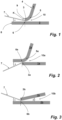
- Figure 1 shows a cross section of an arrangement of the edge sections of a first joining partner 1 and a second joining partner 2 according to a first embodiment.
- the first joining partner 1 comprises a joining flange 3, which is flared or angled relative to the material 4 delimiting the joint.
- the transition between the joining flange 3 and the surrounding material 4 is realized by a curvature 5.
- the second joining partner 2 comprises a joining zone 6.
- the reference number 7 designates a laser beam.
- the side of the joining zone 6 facing the laser beam 7 is spaced from the end 8 - the joint - of this joining partner 2; in this embodiment approximately four times the sheet thickness of the thinner joining partner, whereby in the present embodiment both joining partners 1, 2 are of the same thickness.
- a step-like arrangement - a groove K - is formed.
- the laser beam 7 is focused on the groove K, which is formed by the joint 9 of the joining flange 3 and the joining zone 6.
- the angle ⁇ between the joining zone 6 and the laser beam 7 is approximately 25° in the embodiment shown.
- the center of the laser beam 7 hits the lower third of the joint 9 of the first joining partner 1.
- the joining flange 3 contacts the joining zone 6 in a line contact.
- Figure 2 shows a cross-section of a second embodiment.
- the first joining partner 1a is straight, while the second joining partner 2a has a curved section 5a and is thus partially curved joining zone 6a.
- the joining flange 3a of the joining partner 1a and the joining zone 6a of the second joining partner 2a touch in a line.
- Figure 3 shows a cross-sectional view of another arrangement according to the invention.
- the joining flange 3b of the first joining partner 1b which is straight in this embodiment, is arranged at an angle to the likewise straight joining zone 6b of the second joining partner 2b, namely at an angle ⁇ of approximately 25°.
- the joining flange 3b touches the joining zone 6b in a linear manner.
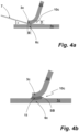
- Figure 4a shows a cross-section of a further embodiment.
- the joining flange 3c of the first joining partner 1c contacts the joining zone 6c of the second joining partner 2c over the entire surface.
- the surface contact in the direction transverse to the side facing the laser beam 7c corresponds approximately to the thickness D of the thinner, in this example the joining flange 3c of the first joining partner 1c, in the width direction B.
- FIG 4b shows the arrangement according to Figure 4a after the laser welding process has been completed. It can be seen in this schematic representation that the weld seam has formed along the contact surface of the two joining partners 1c, 2c and has thus connected the two joining partners 1c and 2c via the joining flange 3c or the joining zone 6c. The melt is identified with the reference number 11. It can be clearly seen that the weld seam is curved towards the first joining partner 1c, due to the gap 10c widening towards the first joining partner 1c.
- the gap 10c arranged on the side facing away from the laser beam 7d can be filled to such an extent that the gap width S is greater than or equal to 0.2 mm and has thus been filled up to this minimum width. Due to the penetration of the molten metal into the gap 10c, a gap bottom SB has been formed, by which the gap width S is limited in the area of its end facing the melt 11. The remaining minimum gap width S is selected such that an anti-corrosion coating, such as a cathodic dip coating, can be easily introduced into the gap up to its gap bottom SB formed by the melt. This means that no uncoatable gaps remain in the gap 10c.
- the Figure 5a shows a microscopic representation of a specimen of two joining partners 1d, 2d welded according to the invention.
- the welding was carried out with a laser beam with a diameter of about 0.8 mm.
- the first joining partner 1d is 1.5 mm thick and the second joining partner 2d is 2 mm thick.
- the weld seam 12 has formed along the contact surface between the joining flange 3d and the joining zone 6d.
- a bulging convex weld seam is formed, forming the gap bottom SB.
Landscapes
- Engineering & Computer Science (AREA)
- Physics & Mathematics (AREA)
- Optics & Photonics (AREA)
- Mechanical Engineering (AREA)
- Plasma & Fusion (AREA)
- Laser Beam Processing (AREA)
Applications Claiming Priority (2)
| Application Number | Priority Date | Filing Date | Title |
|---|---|---|---|
| DE102021107058.9A DE102021107058A1 (de) | 2021-03-22 | 2021-03-22 | Verfahren zum Laserschweißen |
| PCT/EP2022/057402 WO2022200301A1 (de) | 2021-03-22 | 2022-03-22 | Verfahren zum laserschweissen |
Publications (2)
| Publication Number | Publication Date |
|---|---|
| EP4313472A1 EP4313472A1 (de) | 2024-02-07 |
| EP4313472B1 true EP4313472B1 (de) | 2024-11-06 |
Family
ID=81344266
Family Applications (1)
| Application Number | Title | Priority Date | Filing Date |
|---|---|---|---|
| EP22717543.7A Active EP4313472B1 (de) | 2021-03-22 | 2022-03-22 | Verfahren zum laserschweissen |
Country Status (9)
| Country | Link |
|---|---|
| US (1) | US20240165743A1 (pl) |
| EP (1) | EP4313472B1 (pl) |
| CN (1) | CN117120208A (pl) |
| DE (1) | DE102021107058A1 (pl) |
| ES (1) | ES3009468T3 (pl) |
| HU (1) | HUE070025T2 (pl) |
| PL (1) | PL4313472T3 (pl) |
| PT (1) | PT4313472T (pl) |
| WO (1) | WO2022200301A1 (pl) |
Families Citing this family (1)
| Publication number | Priority date | Publication date | Assignee | Title |
|---|---|---|---|---|
| CN119952417B (zh) * | 2024-12-31 | 2026-02-03 | 苏州亿创特智能制造有限公司 | 多腔体型材的辊压焊接成型方法 |
Family Cites Families (9)
| Publication number | Priority date | Publication date | Assignee | Title |
|---|---|---|---|---|
| EP0782489B1 (de) * | 1994-09-23 | 1998-03-18 | Fraunhofer-Gesellschaft zur Förderung der angewandten Forschung e.V. | Verfahren zum verschweissen von werkstücken |
| ES2251724T3 (es) | 1995-11-04 | 2006-05-01 | Volkswagen Aktiengesellschaft | Procedimiento de soldadura laser para chapas de acero revestidas. |
| JP4532984B2 (ja) | 2004-05-14 | 2010-08-25 | 新日本製鐵株式会社 | めっき鋼板のヘリ継手レーザー溶接方法 |
| DE102010029477A1 (de) | 2010-05-28 | 2011-12-01 | Scansonic Mi Gmbh | Verfahren und Vorrichtung zum Laserfügen von Blechteilen |
| DE102010026259A1 (de) * | 2010-07-06 | 2012-01-19 | Daimler Ag | Falzgestaltung einer Bauteilverbindung |
| DE102012013882A1 (de) * | 2012-07-12 | 2013-06-06 | Daimler Ag | Kraftfahrzeugstrukturbauteil und Verfahren zur Herstellung eines Kraftfahrzeugstrukturbauteils |
| DE102013107228B3 (de) | 2013-03-25 | 2014-04-17 | Scansonic Mi Gmbh | Verfahren zum stirnseitigen Laserstrahlschweißen von Bördelflanschen |
| DE102017105900A1 (de) | 2017-03-20 | 2018-09-20 | Kirchhoff Automotive Deutschland Gmbh | Verfahren zum stirnseitigen Laserschweißen |
| DE102017209599A1 (de) | 2017-06-07 | 2018-12-13 | Bayerische Motoren Werke Aktiengesellschaft | Verfahren zur Herstellung eines Bauteilverbundes und Bauteilverbund |
-
2021
- 2021-03-22 DE DE102021107058.9A patent/DE102021107058A1/de active Pending
-
2022
- 2022-03-22 PL PL22717543.7T patent/PL4313472T3/pl unknown
- 2022-03-22 EP EP22717543.7A patent/EP4313472B1/de active Active
- 2022-03-22 ES ES22717543T patent/ES3009468T3/es active Active
- 2022-03-22 WO PCT/EP2022/057402 patent/WO2022200301A1/de not_active Ceased
- 2022-03-22 HU HUE22717543A patent/HUE070025T2/hu unknown
- 2022-03-22 PT PT227175437T patent/PT4313472T/pt unknown
- 2022-03-22 CN CN202280022770.9A patent/CN117120208A/zh active Pending
- 2022-03-22 US US18/551,027 patent/US20240165743A1/en active Pending
Also Published As
| Publication number | Publication date |
|---|---|
| EP4313472A1 (de) | 2024-02-07 |
| PT4313472T (pt) | 2025-02-10 |
| DE102021107058A1 (de) | 2022-09-22 |
| HUE070025T2 (hu) | 2025-05-28 |
| ES3009468T3 (en) | 2025-03-27 |
| PL4313472T3 (pl) | 2025-03-10 |
| US20240165743A1 (en) | 2024-05-23 |
| WO2022200301A1 (de) | 2022-09-29 |
| CN117120208A (zh) | 2023-11-24 |
Similar Documents
| Publication | Publication Date | Title |
|---|---|---|
| EP0771605B1 (de) | Laserschweissverfahren für beschichtete Stahlbleche | |
| EP2509742B1 (de) | VERFAHREN ZUM VERSCHWEIßEN VON ZWEI METALLBAUTEILEN | |
| DE69203419T2 (de) | Verfahren zur Herstellung einer Fahrzeugkarosserieplatte. | |
| EP1005944A2 (de) | Laserstrahl-Schweissverfahren für Überlappnähte an beschichteten Blechen | |
| DE2428828B2 (de) | Verfahren zum Elektronenstrahlverschweißen zweier Metallwerkstücke | |
| EP4313472B1 (de) | Verfahren zum laserschweissen | |
| DE10315976A1 (de) | Verfahren zum Vorbereiten des Fügebereichs eines beschichteten Werkstücks | |
| DE10326870B3 (de) | Verfahren zur Herstellung eines Getriebeschaltelements aus Metall | |
| WO2018224212A1 (de) | Verfahren zur herstellung eines bauteilverbundes und bauteilverbund | |
| EP1711303B1 (de) | Verfahren zur topographieänderung mit laserstrahl von beschichteten blechen und beschichtetes blech mit einer topographieänderung | |
| DE69202224T2 (de) | Verfahren zum Laserstrahlschweissen von beschichteten Bleche. | |
| DE102008036863A1 (de) | Kehlnaht an einem Überlapp- und/oder Parallelstoß und ein Verfahren zur Erzeugung einer solchen Kehlnaht | |
| EP3600755B1 (de) | Verfahren zum stirnseitigen laserschweissen | |
| WO2018149556A1 (de) | Verfahren zum verschweissen zweier blechbauteile und bauteilverbund | |
| EP1797987B1 (de) | Bimetallisches Verbindungselement | |
| DE102004008108B4 (de) | Überlappstoß zum Schweißen von beschichteten Werkstücken | |
| DE102018208787A1 (de) | Laserlötvorrichtung mit nachlaufendem Lötdraht und Laserlötverfahren | |
| DE202021101463U1 (de) | Lasergeschweißte Schweißkonstruktion | |
| DE10237796B3 (de) | Verfahren zum Besäumen eines Blechteils | |
| DE112006001196B4 (de) | Verfahren und Vorrichtung zum thermischen Fügen von Werkstoffen mit hochschmelzenden oxidbehafteten Oberflächen | |
| DE10322449B3 (de) | Verfahren zum Laserschweissen beschichteter Platten | |
| DE102006021911B4 (de) | Hybridschweißverfahren, Schweißnaht sowie Maschinenteil | |
| EP4185436B1 (de) | Laserschweissverfahren zum fügen eines nicht-sintermaterials mit einem sintermaterial und derartig hergestellter verbundkörper | |
| WO2020015921A1 (de) | Verfahren zur herstellung eines fahrzeugbauteils mit fügehilfselement | |
| DE102024127345A1 (de) | Verfahren zum herstellen eines werkstücks mit einer fase, verfahren zum planen einer herstellung eines eine fase aufweisenden werkstücks aus einem rohling sowie laserschneidvorrichtung |
Legal Events
| Date | Code | Title | Description |
|---|---|---|---|
| STAA | Information on the status of an ep patent application or granted ep patent |
Free format text: STATUS: UNKNOWN |
|
| STAA | Information on the status of an ep patent application or granted ep patent |
Free format text: STATUS: THE INTERNATIONAL PUBLICATION HAS BEEN MADE |
|
| PUAI | Public reference made under article 153(3) epc to a published international application that has entered the european phase |
Free format text: ORIGINAL CODE: 0009012 |
|
| STAA | Information on the status of an ep patent application or granted ep patent |
Free format text: STATUS: REQUEST FOR EXAMINATION WAS MADE |
|
| 17P | Request for examination filed |
Effective date: 20231020 |
|
| AK | Designated contracting states |
Kind code of ref document: A1 Designated state(s): AL AT BE BG CH CY CZ DE DK EE ES FI FR GB GR HR HU IE IS IT LI LT LU LV MC MK MT NL NO PL PT RO RS SE SI SK SM TR |
|
| STAA | Information on the status of an ep patent application or granted ep patent |
Free format text: STATUS: EXAMINATION IS IN PROGRESS |
|
| 17Q | First examination report despatched |
Effective date: 20240209 |
|
| P01 | Opt-out of the competence of the unified patent court (upc) registered |
Effective date: 20240215 |
|
| DAV | Request for validation of the european patent (deleted) | ||
| DAX | Request for extension of the european patent (deleted) | ||
| GRAP | Despatch of communication of intention to grant a patent |
Free format text: ORIGINAL CODE: EPIDOSNIGR1 |
|
| STAA | Information on the status of an ep patent application or granted ep patent |
Free format text: STATUS: GRANT OF PATENT IS INTENDED |
|
| INTG | Intention to grant announced |
Effective date: 20240730 |
|
| GRAS | Grant fee paid |
Free format text: ORIGINAL CODE: EPIDOSNIGR3 |
|
| GRAA | (expected) grant |
Free format text: ORIGINAL CODE: 0009210 |
|
| STAA | Information on the status of an ep patent application or granted ep patent |
Free format text: STATUS: THE PATENT HAS BEEN GRANTED |
|
| AK | Designated contracting states |
Kind code of ref document: B1 Designated state(s): AL AT BE BG CH CY CZ DE DK EE ES FI FR GB GR HR HU IE IS IT LI LT LU LV MC MK MT NL NO PL PT RO RS SE SI SK SM TR |
|
| REG | Reference to a national code |
Ref country code: GB Ref legal event code: FG4D Free format text: NOT ENGLISH |
|
| REG | Reference to a national code |
Ref country code: CH Ref legal event code: EP |
|
| REG | Reference to a national code |
Ref country code: DE Ref legal event code: R096 Ref document number: 502022002088 Country of ref document: DE |
|
| REG | Reference to a national code |
Ref country code: IE Ref legal event code: FG4D Free format text: LANGUAGE OF EP DOCUMENT: GERMAN |
|
| REG | Reference to a national code |
Ref country code: PT Ref legal event code: SC4A Ref document number: 4313472 Country of ref document: PT Date of ref document: 20250210 Kind code of ref document: T Free format text: AVAILABILITY OF NATIONAL TRANSLATION Effective date: 20250203 |
|
| REG | Reference to a national code |
Ref country code: LT Ref legal event code: MG9D |
|
| REG | Reference to a national code |
Ref country code: NL Ref legal event code: MP Effective date: 20241106 |
|
| REG | Reference to a national code |
Ref country code: ES Ref legal event code: FG2A Ref document number: 3009468 Country of ref document: ES Kind code of ref document: T3 Effective date: 20250327 |
|
| PG25 | Lapsed in a contracting state [announced via postgrant information from national office to epo] |
Ref country code: HR Free format text: LAPSE BECAUSE OF FAILURE TO SUBMIT A TRANSLATION OF THE DESCRIPTION OR TO PAY THE FEE WITHIN THE PRESCRIBED TIME-LIMIT Effective date: 20241106 Ref country code: IS Free format text: LAPSE BECAUSE OF FAILURE TO SUBMIT A TRANSLATION OF THE DESCRIPTION OR TO PAY THE FEE WITHIN THE PRESCRIBED TIME-LIMIT Effective date: 20250306 |
|
| PG25 | Lapsed in a contracting state [announced via postgrant information from national office to epo] |
Ref country code: FI Free format text: LAPSE BECAUSE OF FAILURE TO SUBMIT A TRANSLATION OF THE DESCRIPTION OR TO PAY THE FEE WITHIN THE PRESCRIBED TIME-LIMIT Effective date: 20241106 Ref country code: NL Free format text: LAPSE BECAUSE OF FAILURE TO SUBMIT A TRANSLATION OF THE DESCRIPTION OR TO PAY THE FEE WITHIN THE PRESCRIBED TIME-LIMIT Effective date: 20241106 |
|
| PG25 | Lapsed in a contracting state [announced via postgrant information from national office to epo] |
Ref country code: BG Free format text: LAPSE BECAUSE OF FAILURE TO SUBMIT A TRANSLATION OF THE DESCRIPTION OR TO PAY THE FEE WITHIN THE PRESCRIBED TIME-LIMIT Effective date: 20241106 |
|
| PG25 | Lapsed in a contracting state [announced via postgrant information from national office to epo] |
Ref country code: NO Free format text: LAPSE BECAUSE OF FAILURE TO SUBMIT A TRANSLATION OF THE DESCRIPTION OR TO PAY THE FEE WITHIN THE PRESCRIBED TIME-LIMIT Effective date: 20250206 |
|
| PG25 | Lapsed in a contracting state [announced via postgrant information from national office to epo] |
Ref country code: LV Free format text: LAPSE BECAUSE OF FAILURE TO SUBMIT A TRANSLATION OF THE DESCRIPTION OR TO PAY THE FEE WITHIN THE PRESCRIBED TIME-LIMIT Effective date: 20241106 Ref country code: GR Free format text: LAPSE BECAUSE OF FAILURE TO SUBMIT A TRANSLATION OF THE DESCRIPTION OR TO PAY THE FEE WITHIN THE PRESCRIBED TIME-LIMIT Effective date: 20250207 |
|
| PG25 | Lapsed in a contracting state [announced via postgrant information from national office to epo] |
Ref country code: RS Free format text: LAPSE BECAUSE OF FAILURE TO SUBMIT A TRANSLATION OF THE DESCRIPTION OR TO PAY THE FEE WITHIN THE PRESCRIBED TIME-LIMIT Effective date: 20250206 |
|
| REG | Reference to a national code |
Ref country code: HU Ref legal event code: AG4A Ref document number: E070025 Country of ref document: HU |
|
| PG25 | Lapsed in a contracting state [announced via postgrant information from national office to epo] |
Ref country code: SM Free format text: LAPSE BECAUSE OF FAILURE TO SUBMIT A TRANSLATION OF THE DESCRIPTION OR TO PAY THE FEE WITHIN THE PRESCRIBED TIME-LIMIT Effective date: 20241106 |
|
| PGFP | Annual fee paid to national office [announced via postgrant information from national office to epo] |
Ref country code: PL Payment date: 20250509 Year of fee payment: 4 |
|
| PG25 | Lapsed in a contracting state [announced via postgrant information from national office to epo] |
Ref country code: DK Free format text: LAPSE BECAUSE OF FAILURE TO SUBMIT A TRANSLATION OF THE DESCRIPTION OR TO PAY THE FEE WITHIN THE PRESCRIBED TIME-LIMIT Effective date: 20241106 |
|
| PGFP | Annual fee paid to national office [announced via postgrant information from national office to epo] |
Ref country code: ES Payment date: 20250519 Year of fee payment: 4 |
|
| PGFP | Annual fee paid to national office [announced via postgrant information from national office to epo] |
Ref country code: PT Payment date: 20250521 Year of fee payment: 4 |
|
| PG25 | Lapsed in a contracting state [announced via postgrant information from national office to epo] |
Ref country code: EE Free format text: LAPSE BECAUSE OF FAILURE TO SUBMIT A TRANSLATION OF THE DESCRIPTION OR TO PAY THE FEE WITHIN THE PRESCRIBED TIME-LIMIT Effective date: 20241106 |
|
| PG25 | Lapsed in a contracting state [announced via postgrant information from national office to epo] |
Ref country code: SK Free format text: LAPSE BECAUSE OF FAILURE TO SUBMIT A TRANSLATION OF THE DESCRIPTION OR TO PAY THE FEE WITHIN THE PRESCRIBED TIME-LIMIT Effective date: 20241106 |
|
| PGFP | Annual fee paid to national office [announced via postgrant information from national office to epo] |
Ref country code: CZ Payment date: 20250509 Year of fee payment: 4 |
|
| PG25 | Lapsed in a contracting state [announced via postgrant information from national office to epo] |
Ref country code: IT Free format text: LAPSE BECAUSE OF FAILURE TO SUBMIT A TRANSLATION OF THE DESCRIPTION OR TO PAY THE FEE WITHIN THE PRESCRIBED TIME-LIMIT Effective date: 20241106 |
|
| REG | Reference to a national code |
Ref country code: DE Ref legal event code: R097 Ref document number: 502022002088 Country of ref document: DE |
|
| PG25 | Lapsed in a contracting state [announced via postgrant information from national office to epo] |
Ref country code: SE Free format text: LAPSE BECAUSE OF FAILURE TO SUBMIT A TRANSLATION OF THE DESCRIPTION OR TO PAY THE FEE WITHIN THE PRESCRIBED TIME-LIMIT Effective date: 20241106 |
|
| PLBE | No opposition filed within time limit |
Free format text: ORIGINAL CODE: 0009261 |
|
| STAA | Information on the status of an ep patent application or granted ep patent |
Free format text: STATUS: NO OPPOSITION FILED WITHIN TIME LIMIT |
|
| PG25 | Lapsed in a contracting state [announced via postgrant information from national office to epo] |
Ref country code: MC Free format text: LAPSE BECAUSE OF FAILURE TO SUBMIT A TRANSLATION OF THE DESCRIPTION OR TO PAY THE FEE WITHIN THE PRESCRIBED TIME-LIMIT Effective date: 20241106 |
|
| 26N | No opposition filed |
Effective date: 20250807 |
|
| REG | Reference to a national code |
Ref country code: CH Ref legal event code: H13 Free format text: ST27 STATUS EVENT CODE: U-0-0-H10-H13 (AS PROVIDED BY THE NATIONAL OFFICE) Effective date: 20251024 |
|
| PG25 | Lapsed in a contracting state [announced via postgrant information from national office to epo] |
Ref country code: LU Free format text: LAPSE BECAUSE OF NON-PAYMENT OF DUE FEES Effective date: 20250322 |
|
| REG | Reference to a national code |
Ref country code: BE Ref legal event code: MM Effective date: 20250331 |
|
| PG25 | Lapsed in a contracting state [announced via postgrant information from national office to epo] |
Ref country code: BE Free format text: LAPSE BECAUSE OF NON-PAYMENT OF DUE FEES Effective date: 20250331 |
|
| PG25 | Lapsed in a contracting state [announced via postgrant information from national office to epo] |
Ref country code: CH Free format text: LAPSE BECAUSE OF NON-PAYMENT OF DUE FEES Effective date: 20250331 |
|
| PG25 | Lapsed in a contracting state [announced via postgrant information from national office to epo] |
Ref country code: IE Free format text: LAPSE BECAUSE OF NON-PAYMENT OF DUE FEES Effective date: 20250322 |
|
| PGFP | Annual fee paid to national office [announced via postgrant information from national office to epo] |
Ref country code: DE Payment date: 20260320 Year of fee payment: 5 |
|
| PGFP | Annual fee paid to national office [announced via postgrant information from national office to epo] |
Ref country code: AT Payment date: 20260301 Year of fee payment: 5 |
|
| PGFP | Annual fee paid to national office [announced via postgrant information from national office to epo] |
Ref country code: RO Payment date: 20260316 Year of fee payment: 5 |
|
| PGFP | Annual fee paid to national office [announced via postgrant information from national office to epo] |
Ref country code: HU Payment date: 20260313 Year of fee payment: 5 |
|
| PGFP | Annual fee paid to national office [announced via postgrant information from national office to epo] |
Ref country code: FR Payment date: 20260324 Year of fee payment: 5 |