EP4312934B1 - Schenkelpositioniersystem - Google Patents
Schenkelpositioniersystem Download PDFInfo
- Publication number
- EP4312934B1 EP4312934B1 EP22718206.0A EP22718206A EP4312934B1 EP 4312934 B1 EP4312934 B1 EP 4312934B1 EP 22718206 A EP22718206 A EP 22718206A EP 4312934 B1 EP4312934 B1 EP 4312934B1
- Authority
- EP
- European Patent Office
- Prior art keywords
- limb
- positioning system
- clutch
- pivoting member
- support
- Prior art date
- Legal status (The legal status is an assumption and is not a legal conclusion. Google has not performed a legal analysis and makes no representation as to the accuracy of the status listed.)
- Active
Links
Images




Classifications
-
- A—HUMAN NECESSITIES
- A61—MEDICAL OR VETERINARY SCIENCE; HYGIENE
- A61G—TRANSPORT, PERSONAL CONVEYANCES, OR ACCOMMODATION SPECIALLY ADAPTED FOR PATIENTS OR DISABLED PERSONS; OPERATING TABLES OR CHAIRS; CHAIRS FOR DENTISTRY; FUNERAL DEVICES
- A61G13/00—Operating tables; Auxiliary appliances therefor
- A61G13/0036—Orthopaedic operating tables
- A61G13/0045—Orthopaedic operating tables specially adapted for hand or wrist surgeries
-
- A—HUMAN NECESSITIES
- A61—MEDICAL OR VETERINARY SCIENCE; HYGIENE
- A61G—TRANSPORT, PERSONAL CONVEYANCES, OR ACCOMMODATION SPECIALLY ADAPTED FOR PATIENTS OR DISABLED PERSONS; OPERATING TABLES OR CHAIRS; CHAIRS FOR DENTISTRY; FUNERAL DEVICES
- A61G13/00—Operating tables; Auxiliary appliances therefor
- A61G13/0036—Orthopaedic operating tables
- A61G13/0063—Orthopaedic operating tables specially adapted for knee surgeries
-
- A—HUMAN NECESSITIES
- A61—MEDICAL OR VETERINARY SCIENCE; HYGIENE
- A61G—TRANSPORT, PERSONAL CONVEYANCES, OR ACCOMMODATION SPECIALLY ADAPTED FOR PATIENTS OR DISABLED PERSONS; OPERATING TABLES OR CHAIRS; CHAIRS FOR DENTISTRY; FUNERAL DEVICES
- A61G13/00—Operating tables; Auxiliary appliances therefor
- A61G13/10—Parts, details or accessories
- A61G13/101—Clamping means for connecting accessories to the operating table
-
- A—HUMAN NECESSITIES
- A61—MEDICAL OR VETERINARY SCIENCE; HYGIENE
- A61G—TRANSPORT, PERSONAL CONVEYANCES, OR ACCOMMODATION SPECIALLY ADAPTED FOR PATIENTS OR DISABLED PERSONS; OPERATING TABLES OR CHAIRS; CHAIRS FOR DENTISTRY; FUNERAL DEVICES
- A61G13/00—Operating tables; Auxiliary appliances therefor
- A61G13/10—Parts, details or accessories
- A61G13/12—Rests specially adapted therefor; Arrangements of patient-supporting surfaces
- A61G13/1205—Rests specially adapted therefor; Arrangements of patient-supporting surfaces for specific parts of the body
- A61G13/1245—Knees, upper or lower legs
-
- A—HUMAN NECESSITIES
- A61—MEDICAL OR VETERINARY SCIENCE; HYGIENE
- A61G—TRANSPORT, PERSONAL CONVEYANCES, OR ACCOMMODATION SPECIALLY ADAPTED FOR PATIENTS OR DISABLED PERSONS; OPERATING TABLES OR CHAIRS; CHAIRS FOR DENTISTRY; FUNERAL DEVICES
- A61G13/00—Operating tables; Auxiliary appliances therefor
- A61G13/10—Parts, details or accessories
- A61G13/12—Rests specially adapted therefor; Arrangements of patient-supporting surfaces
- A61G13/128—Rests specially adapted therefor; Arrangements of patient-supporting surfaces with mechanical surface adaptations
- A61G13/1295—Rests specially adapted therefor; Arrangements of patient-supporting surfaces with mechanical surface adaptations having alignment devices for the patient's body
-
- A—HUMAN NECESSITIES
- A61—MEDICAL OR VETERINARY SCIENCE; HYGIENE
- A61G—TRANSPORT, PERSONAL CONVEYANCES, OR ACCOMMODATION SPECIALLY ADAPTED FOR PATIENTS OR DISABLED PERSONS; OPERATING TABLES OR CHAIRS; CHAIRS FOR DENTISTRY; FUNERAL DEVICES
- A61G2200/00—Information related to the kind of patient or his position
- A61G2200/30—Specific positions of the patient
- A61G2200/32—Specific positions of the patient lying
- A61G2200/327—Specific positions of the patient lying supine
-
- A—HUMAN NECESSITIES
- A61—MEDICAL OR VETERINARY SCIENCE; HYGIENE
- A61G—TRANSPORT, PERSONAL CONVEYANCES, OR ACCOMMODATION SPECIALLY ADAPTED FOR PATIENTS OR DISABLED PERSONS; OPERATING TABLES OR CHAIRS; CHAIRS FOR DENTISTRY; FUNERAL DEVICES
- A61G2203/00—General characteristics of devices
- A61G2203/70—General characteristics of devices with special adaptations, e.g. for safety or comfort
- A61G2203/78—General characteristics of devices with special adaptations, e.g. for safety or comfort for clamping
-
- A—HUMAN NECESSITIES
- A61—MEDICAL OR VETERINARY SCIENCE; HYGIENE
- A61G—TRANSPORT, PERSONAL CONVEYANCES, OR ACCOMMODATION SPECIALLY ADAPTED FOR PATIENTS OR DISABLED PERSONS; OPERATING TABLES OR CHAIRS; CHAIRS FOR DENTISTRY; FUNERAL DEVICES
- A61G2210/00—Devices for specific treatment or diagnosis
- A61G2210/10—Devices for specific treatment or diagnosis for orthopedics
Definitions
- the present invention relates to the field of surgical support system.
- the present invention relates to the field of systems for positioning and maintaining immobilized a limb of a patient in a desired position with respect to a surgical table during orthopedic surgery
- Such a system is disclosed in the US4886258 .
- a leg stabilizer located under the foot.
- a leg stabilizer consists of a support element (i.e., a cushion) which is located on the surgical table so that, when the sole of the foot rests on said support element, the leg is maintained in a desired flexion position, wherein the thigh and the calf forms an angle inferior to 180 degrees.
- a second support element may be further placed on a side of the leg, to prevent the leg from falling on external side of the surgical table.
- This solution is simple (static and fully manual), easy to use and compact. The surgeon can easily release the leg from the previously set flexion position. It is then easy to make the ligament balancing evaluation of the patient's leg in extension. However, the leg is not firmly attached and maintained at a dedicated flexion position (i.e., not immobilized). This solution does not strain the leg fully, the flexion position obtained is approximative and the holding into position is loosy.
- patent EP 1 940 337 B1 proposes a system allowing the positioning and holding of the leg in a flexion position using a cradle supporting the limb of the patient (by the thigh) with respect to the lateral rail of the surgical table and means for positioning said cradle with respect to multiple axis.
- the system of this patent presents some disadvantages: (1) many backlashes in the settings which reduce the rigidity of the leg immobilization, (2) the range of motion of the cradle is not symmetric, therefore a mechanical operation is necessary in order to pass from a configuration for operating a left leg to a configuration for operating a right leg (or the inverse), (3) the adjustment and adaption of the system to the patient is difficult because of the numerous and discrete settings which are not intuitive and not easy to understand (i.e., a training and learning phase is necessary to properly mount and adjust said system), (4) the use of a cradle under the thigh makes impossible for the surgeon to set the leg in the hyper flexion position while the leg is attached to the system and (5) the system is commanded by the user through foot pedals, which is prone to errors and misuse during surgery.
- the system of the present invention provides a solution for here-above mentioned issues by using a simpler structure which is more ergonomic and easier to use for the surgeon.
- the present invention relates to a limb positioning system for positioning and maintaining immobilized a limb of a patient in a desired position with respect to a surgical table during orthopedic surgery.
- the system comprising:
- the present invention provides a system that, thanks to the configuration of the clutch and the pivoting member, allows an easily immobilization of a limb in a desired position during a surgical operation, which increases precision of gestures, and easily release of the limb so as to allow the surgeon to freely manipulate the limb during the operation.
- This manipulation helps the surgeon in its operation and ensures in fine that the patient will regain natural movement of the limb after surgery.
- the present system is compact which leaves more free space to the surgeon for the manipulation of the limb and during the surgery.
- the range of motion allowed by the pivoting member of the system to position the limb is symmetrical, thus the system may be easily installed without needing any further tuning for operating on the left or the right limb alternatively, thus mounted on the left or right side of the surgical table.
- the different features of the invention cooperate so as to provide a system which is easily adaptable to the patient with little adjustments required, this advantageously reduces the time necessary to install the patient in a configuration for the surgery.
- the configuration of the clutch and the pivoting member allows to position and secure the limb of the subject to the system so that the rotational axis passes through the center of the hip of the subject.
- fixation member configured to maintain the system in position with respect to the surgical table (instead for example of the systems maintained by a base structure positioned directly on the floor) allows to install the system to any standard surgical table without need to modify the surgical table itself.
- the simplicity of the system simplifies the manufacture of the system and allows to reduce cost of production.
- the limb positioning system according to the invention may comprise one or several of the following features, taken in isolation or combined with each other:
- the pivoting member is movable relative to the clutch for varying a distance between the longitudinal axis and the rotation axis. This embodiment advantageously allows to adapt the system to different morphologies of patients, notably to adapt the system to the height of the patient's limb.
- the fixation member is configured to clamp the system to the surgical table, preferably to a rail of the surgical table, so that no change of the surgical table is required.
- the fixation member may be adapted to be clamped onto the existing surgical table through the rails.
- the fixation member comprises a setting module configured to modify the position of the pivoting member, the support member and the clutch in a plane orthogonal to the rotation axis.
- the fixation member advantageously allows to align the rotational axis to a predefined anatomical reference of the patient, for example the center of the hip of the subject, whenever the limb to be operated is a leg.
- the system further comprises a weight compensation device configured to provide a weight compensation force to the pivoting member, said force being opposed to a weight of the limb applied to the pivoting member.
- the clutch is only configured to be in an open configuration and a locked configuration.
- the weight compensation device advantageously allows to assist the surgeon to reposition the limb with ease when the clutch is in the open configuration so that the surgeons does not have to support all the weight of the limb.
- the weight compensation device is a passive device, preferably a spring, or an active device, such as an actuator.
- the support member comprises a hanging element that is positioned with respect to the pivoting member so that, when the system is in use, the limb is hanged (or suspended) from the longitudinal portion of the pivoting member.
- the hanging element is releasably connected to said longitudinal portion via the support hooking part.
- Said hanging element is an annular part.
- the longitudinal portion is always placed on top of the limb, which advantageous allow to free the space between the hanged limb and the surgical table from any disturbing element.
- this configuration allows to have the anterior part of the limb free from any cumbersome mechanism (i.e., only hanging element present), which allows the surgeon to perform a wider range of movement with the limb.
- hyper-flexion of the leg is thus permitted, so as full extension of the leg on the surgical table.
- the support member comprises an annular part configured to surround the limb, wherein the annular part is positioned with respect to the pivoting member so that the limb is hanged (or suspended) on the longitudinal portion of the pivoting member using the annular part.
- This particular arrangement having the pivoting member placed on top of the limb, is advantageous as it frees the space between the hanged limb and the surgical table from any disturbing element.
- this configuration allows to have the anterior part of the limb free from any cumbersome mechanism (i.e., only annular part present), which allows the surgeon to perform a wider range of movement with the limb.
- hyper flexion of the leg is thus permitted, so as full extension of the leg on the surgical table.
- the support hooking part is connected to the annular part and is detachable from the longitudinal portion of the pivoting member. This embodiment enables a quick release of the patient in case of an emergency stop of the procedure. This embodiment further simplifies the installation of the support member.
- the system further comprises a bone grasping support having a first portion fixed to the pivoting member and comprising, at one end of a second portion, a grasping member configured to be rigidly fixed to at least one bone of the patient.
- a bone grasping support having a first portion fixed to the pivoting member and comprising, at one end of a second portion, a grasping member configured to be rigidly fixed to at least one bone of the patient.
- the clutch is a brake, preferably an electromagnetic power off brake. The use of a brake is much more advantageous than using a gear motor since they comprise a lot of fragile moving parts that are subject to mechanical wear, they are more compact, easy to design and to manufacture.
- the system comprises a switching member for switching the clutch between the open configuration and locked configuration.
- the switching member is located below the rotation axis and at a predetermined distance from the floor when the system is in a normal use configuration. This specific location of the switching member allows the surgeon and/or a member of the medical staff to push the switching member with a part of his/her leg so as to keep the hands free to manipulate the limb.
- the switching member may be located at a height allowing a person to push it with his/her knee.
- the switching member may be a foot switch configured to be placed on the floor.
- the switching member comprises two switches located respectively on both sides of the fixation member. This embodiment allows the surgeon and/or a member of the medical staff to activate/disactivate the clutch by pushing on the switching member from both sides of the fixation member.
- the switches are advantageously in a symmetrical position with respect to rotation axis, so that the surgeon operating the right or left limb will be able to activate/disactivate the clutch with the same movement which is cognitively easier.
- the present invention also relates to an assembly comprising a limb positioning system according to any one of the embodiments described above and a surgical robotic device, wherein the limb positioning system and robotic device are connected to each other.
- the surgical robotic device comprises at least one movable member configured to pivot around a rotation axis coinciding with the rotation axis of the pivoting member of the limb positioning system.
- the surgical robotic device is a surgical assistance robotic device for knee joint arthroplasty.
- a limb positioning system 10 according to an embodiment of the present invention will now be described with reference to Figure 1 .
- the limb is a leg L of the patient and the positioning system 10 comprises a pivoting member 20, a support member 30 configured to support the limb of the patient, a clutch 40 connected to the pivoting member 20 and a fixation member 50.
- the pivoting member 20 has a longitudinal first portion 21 extending along a corresponding longitudinal axis A L .
- the pivoting member is configured so as that, when the system is in a normal use configuration, the longitudinal axis A L always belong to a plane parallel to the surgical table T, no matter the position of the pivoting member 20 with respect to the table T.
- the pivoting member 20 may comprise a second portion 22 that connects the longitudinal portion 21 to the clutch 40.
- the second portion 22 is substantially perpendicular or transversal to the longitudinal portion 21 and the longitudinal axis A L .
- the longitudinal axis A L extends in direction Z ( Fig. 2 ).
- the longitudinal portion 21 extending along a corresponding longitudinal axis A L may be directly connected to the clutch (not represented).
- the second portion 22 can be adjusted by varying a distance between the longitudinal axis A L and the rotation axis A R .
- multiple pivoting member 20 with a various length for the second portion 22 may be available to be coupled with the clutch. The surgeon will have to choose the length of the second portion according to the morphology of the patient.
- the clutch 40 may be configured to receive a part of variating length of the second portion 22, the length of the part inserted into the clutch 40 being determined by the surgeon to fit the morphology of the patient.
- the support member 30 comprises a support hooking part 31 connected to said longitudinal portion 21 and a hanging element configured to receive and support the limb.
- Said hanging element is positioned with respect to the pivoting member so that, when the system is in a normal use configuration, the limb is hanged (or suspended) from the longitudinal portion of the pivoting member.
- the hanging element may be an annular part 32 configured to receive and support the limb, said annular part 32 being movably connected to the said longitudinal portion 21 through the support hooking part 31.
- the annular part 32 is connected to the support hooking part 31 so that when the limb is correctly placed into the annular part 32, said limb is hanged from the longitudinal portion 21 of the pivoting member 20.
- the annular part 32 is configured to be fastened around the thigh of the patient.
- This is particularly advantageous since thanks to this configuration hanging the thigh, the area between the anterior part of the thigh, the calf and the surgical table is free from any obstacle, so that the surgeon performing a knee arthroplasty surgery can put the leg of the patient either in hyper flexion (i.e., calf in contact with the rear of the thigh), flexion or full extension (i.e., leg elongated laying on the table) with ease and without any disturbance.
- This embodiment also advantageously allows an easier take in hand of the limb by the surgeon as no component of the system prevents the surgeon to place his/her hands on any anterior part of the limb to lift it and perform the desired manipulation.
- the annular part 32 may be a strip of fabric comprising fastening means allowing to close the strip into the annular shape, forming the annular part 32.
- Multiple fastening means such as for example Velcro straps, may be positioned into both extremities of the strips in order to allow the strip to be closed into an annular part 32 so as to better adapt to the morphology of the patient.
- the annular part 32 may be an orthosis.
- the support hooking part 31 is movable along said longitudinal portion 21 so that the position of the support member 30 can be easily adjusted to each specific patient, and may be then clamped (not represented) to block the position of the support member 30 along the longitudinal axis A L
- the support hooking part 31 may be detachably connected to the annular part 32 so that the annular part 32 hanging the limb may be detachable at any moment from the longitudinal portion 21.
- the support hooking part 31 may comprise a switch or a pushbutton that once pushed frees the annular part 32 from the support hooking part 31. This feature is particularly advantageous since it allows to quickly release the patient from the system in case of an emergency stop of the surgical procedure.
- the clutch may be configured to allow the pivoting element to cover an angle range of 180 degrees when no patient is connected to the support element 30.
- the pivoting element 20 can cover, for example, an angle range of 20 to 90 degrees.
- the brake of the clutch is activated and the pivoting member 20 is immobilized in a desired (angular) position so that the limb L of the patient is hanged in a desired position.
- the system when the system is adapted to support a leg, it does not comprise any support to fix the corresponding foot in a predefine position; the foot is simply placed on the surgical table at an adequate distance from the thigh. The surgeon may find the most suitable configuration of the leg for each step of the surgical procedure, being free to change said configuration at any moment.
- the system is maintained in position with respect to the surgical table T thanks to the fixation member 50.
- the fixation member 50 may be a monoblock or as a single piece, which therefore allows to fix the system in only one position with respect to the surgical table.
- the fixation member 50 may comprise a setting module allowing a fine tuning of the position of the system with respect to the surgical table T. This alternative will be described in details in association to Figure 3 .
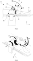
- Figure 2 which provides a top view of the system of the invention, clearly shows that the rotation axis A R is parallel to the longitudinal axis A L . Furthermore, Figure 2 shows as well the surgical table T and the rail R of the surgical table, which are not part of the system.
- the fixation member 50 is configured to clamp the system to the surgical table T.
- the fixation member 50 may be notably configured to be fixed on one rail R of the surgical table.
- the fixation member 50 may further comprise a setting module shown in Figure 3 .
- Figure 3 is a side view of the system 10.
- Figure 3 is here used to describe the setting module which is configured to modify the position of the pivoting member 20, the support member 30 and the clutch 40 in a plane orthogonal to the rotation axis (A R ).
- the setting module comprises a first platform 51 which is configured to modify the position of the system, once fixed on the surgical table, along a longitudinal direction X of the surgical table (i.e., horizontally with respect to the floor).
- This first platform 51 may be configured to be the portion of the fixation element that is able to clamp the system 10 to the surgical table T, for example by means of clips.
- the setting module comprises as well a second platform 52 configured to displace the system 10 along a vertical direction Y (i.e., a direction parallel to an axis perpendicular to the surgical table T plane).
- the second platform 52 may comprise a crank handle or be motorized in order to obtain the vertical displacement.
- the second platform 52 may be fixed onto the first platform 51, and be connected to the clutch 40.
- FIG. 3 shows as well that the clutch 40 may comprise an external housing 42 configured to comprise and protect from the external environment, the brake 41 and at least part of the weight compensation device 43.
- the brake 41 may be electromagnetic brake, more precisely electromagnetic power-off brake, meaning that the brake is into its locked configuration when no electrical current flows through it.
- a permanent magnet inside said brake ensures that it remains in its locked configuration when no current flows through it.
- the weight compensation device 43 is configured to provide a weight compensation force to the pivoting member 20 supporting the limb. Said force is opposed to a weight of the limb, the weight being herein considered as a vector quantity representing the gravitational force acting on the limb.
- the weight may have a magnitude depending from a portion of the mass of the limb. Indeed, when the limb is a leg, the foot is usually positioned on the surgical table. This embodiment allows, when the clutch is in the open configuration, to advantageously assists a surgeon to lift the leg, during the positioning of the leg and the setup of the knee, as well as during soft tissue balancing manipulations.
- the weight compensation device 43 may be a passive device, such as a spring-based mechanism, which exerts a restoring force whenever the spring is pulled or pushed by the pivoting member 20 which support the weight of the limb.
- the weight compensation device 43 may be an active device, such as an actuator connected to the pivoting member 20.
- the system further comprises a switching member (60a, 60b) for switching the clutch between the open configuration and locked configuration.
- This switching member (60a, 60b) may be located below the rotation axis and at a predetermined distance from the floor when the system is in a normal use configuration so that the surgeon may push the switching member by applying a pressure with his/her knee.
- the switching member comprises two switches 60a and 60b located respectively on both sides of the fixation member.
- each switching member 60a or 60b is activated by a substantially horizontal push (i.e. in a direction substantially parallel to the floor or the table T).
- the switching member may comprise a single switch (not represented) positioned on the external surface of the second platform 52 (i.e., the surface of the second platform 52 that is not facing the surgical table).
- the advantage of positioning the switching member at the height of the surgeon's knee is that he/she will be able to push the switch with a simple movement of his/her leg while using his/her arms to manipulate the limb of the patient.
- the switching member for switching the clutch between the open configuration and locked configuration may be a simple pedal positioned on the floor.
- pushing the switch member with the knee or a part of the thigh (depending on the height of the surgeon) is easier and safer than searching with the feet for a switch disposed on the floor.
- Figure 4 shows a lateral view of the leg of the patient wherein the thigh is positioned inside the annular part 32 in different positions allowed by the system.
- the leg may be disposed in an extension position E ( Fig. 4 ) wherein the leg rests on the surgical table, not applying any force on the support member 30, and the clutch may be therefore in the unlocked configuration. Then, while the clutch is in the unlocked configuration, the surgeon may change the position of the leg to a flexion position F wherein the thigh and the calf forms an angle of less than 180 degrees. As shown in this Figure 4 , the support member 30 and the pivoting member 20 move with the thigh to which they are connected. To maintain the leg in this flexion position F, the clutch is switched to the locked configuration and the feet is positioned in an appropriate emplacement on the surgical table.
- the specific configuration of the support member 30 allows as well the surgeon to further push the calf against the thigh so as to reach the specific flexion position called hyper-flexion position H.
- the clutch 40 had been switched into the open configuration and switched back to the locked configuration once the hyper-flexion position had been reached.
- the arrow F1 provide a visual representation of the movement of the pivoting element 20 and the thigh of the patient when changing from the extension position E to a flexion position (F, H) and inversely.
- Figure 5 provides a perspective view of the system, showing with the arrow F1 the pivoting movement of the thigh around the rotation axis. This pivoting movement is allowed by the support element 20 turning around the rotation axis when the clutch is in the open position.
- Arrows F2 and F3 represents the direction of displacement of the calf during manipulation of the leg by the surgeon (hands of the surgeon are represented manipulating the leg in Figure 6 ), when the clutch is in the locked configuration.
- Figure 7 shows a configuration wherein the system 10 further comprises a bone grasping support 70 to rigidly fix a bone of the patient in a desired position.
- the bone grasping support 70 has a first portion 71 fixed to an end of the pivoting member 20 opposite to the clutch 40, and comprises a second portion 72 hinged connected to said first portion 71.
- the end of the second portion 72 opposite to the hinged connection comprises a grasping member 73 configured to be rigidly fixed to at least one bone of the patient.
- the first portion 71 extends here in a direction transversal to the longitudinal portion 21 of the pivoting member.
- the hinged connection may comprise a locking element that allows to block the hinged connection in a desired fixed position of the first portion 71 with respect to the second portion 72.
- This embodiment advantageously allows to first move the first portion 71 and the second portion 72 in order to adapt the bone grasping support 70 to the morphology of the patient, secondly to provide a rigid connection between the pivoting member 20 and the bone when the locking element blocks the first portion 71 and the second portion 72 in the desired fixed position.
- the grasping member 73 may comprises surgical screws allowing to fix the system for example to the tibia or femur of the patient.
- Such a bone grasping support 70 is well integrated in the system, thus resulting in a compact design and more room for the surgeon.
- Figure 8 shows an assembly comprising a limb positioning system 10 according to an embodiment of the invention, and a surgical robotic device 80, wherein the limb positioning system and robotic device are connected to each other's.
- the surgical robotic device 80 comprises at least one movable member 81 configured to pivot around a rotation axis coinciding with the rotation axis A R of the pivoting member of the limb positioning system.
- the robot and the positioning system may thus be referenced relative to a same axis, thus improving precision of the surgical robotic device.
- precision of the robotic device 80 is also improved due to the fixed position of the bone to which the device 70 is attached.
Landscapes
- Health & Medical Sciences (AREA)
- Engineering & Computer Science (AREA)
- Biomedical Technology (AREA)
- Life Sciences & Earth Sciences (AREA)
- Animal Behavior & Ethology (AREA)
- General Health & Medical Sciences (AREA)
- Public Health (AREA)
- Veterinary Medicine (AREA)
- Orthopedic Medicine & Surgery (AREA)
- Accommodation For Nursing Or Treatment Tables (AREA)
- Executing Machine-Instructions (AREA)
- Attitude Control For Articles On Conveyors (AREA)
- Vehicle Body Suspensions (AREA)
Claims (13)
- Gliedmaßenpositionierungssystem (10) zum Positionieren und Immobilisierthalten einer Gliedmaße (L) eines Patienten in einer gewünschten Position in Bezug auf einen Operationstisch (T) während einer orthopädischen Operation konfiguriert ist, wobei das System umfasst:- ein Schwenkelement (20), das einen Längsabschnitt (21) aufweist, der sich entlang einer entsprechenden Längsachse erstreckt, wobei das Schwenkelement (20) derart konfiguriert ist, dass die Längsachse (AL) zum Operationstisch (T) parallel ist, wenn sich das System in einer normalen Gebrauchskonfiguration befindet;- ein Halteelement (30), das so konfiguriert ist, dass es die Gliedmaße des Patienten hält; wobei das Halteelement einen Haltehakenteil (31) umfasst, der mit dem Längsabschnitt (21) verbunden ist und entlang des Längsabschnitts bewegt werden kann;- eine mit dem Schwenkelement (20) verbundene Kupplung (40), die eine offene Konfiguration und eine arretierte Konfiguration aufweist, wobei die Kupplung in der offenen Konfiguration das Schwenken des Schwenkelements um eine sich von der Längsachse unterscheidende Drehachse (AR), die zur Längsachse (AL) parallel ist, gestattet, und wobei die Kupplung (40) in der arretierten Konfiguration die Immobilisierung des Schwenkelements (20) in der gewünschten Position ermöglicht;- mindestens ein Befestigungselement (50), das so konfiguriert ist, dass es das System in Bezug auf den Operationstisch (T) in Position hält, undwobei das Halteelement (30) ein Hängeelement umfasst, das aus einem ringförmigen Teil (32) besteht, der beweglich mit dem Längsabschnitt (21) über den Haltehakenteil (31) verbunden ist, wobei der ringförmige Teil (32) ist so konfiguriert, dass der so konfiguriert ist, dass er das Glied umschließt und das Glied vom Längsabschnitt (21) des schwenkbaren Elements (20) abhängt.
- Gliedmaßenpositionierungssystem nach Anspruch 1, wobei das Schwenkelement (20) relativ zur Kupplung (40) bewegt werden kann, um einen Abstand zwischen der Längsachse (AL) und der Drehachse (AR) zu variieren.
- Gliedmaßenpositionierungssystem nach Anspruch 1 oder 2, wobei das Befestigungselement (50) so konfiguriert ist, dass es das System am Operationstisch (T), vorzugsweise an einer Schiene (R) des Operationstisches, festklemmt.
- Gliedmaßenpositionierungssystem nach einem der Ansprüche 1 bis 3, wobei das Befestigungselement (50) ein Einstellmodul (51, 52) umfasst, das so konfiguriert ist, dass es die Position des Schwenkelements (20), des Halteelements (30) und der Kupplung (40) in einer zur Drehachse (AR) orthogonalen Ebene verändert.
- Gliedmaßenpositionierungssystem nach einem der Ansprüche 1 bis 4, die weiter eine Gewichtskompensationsvorrichtung (43) umfasst, die so konfiguriert ist, dass sie eine Gewichtskompensationskraft für das Schwenkelement (20) bereitstellt, wobei die Kraft einem Gewicht der Gliedmaße, das am Schwenkelement (20) anliegt, entgegengesetzt ist.
- Gliedmaßenpositionierungssystem nach Anspruch 5, wobei die Gewichtskompensationsvorrichtung (43) eine passive Vorrichtung, vorzugsweise eine Feder, oder eine aktive Vorrichtung, wie etwa ein Aktor, ist.
- Gliedmaßenpositionierungssystem nach einem der Ansprüche 1 bis 6, die weiter eine Knochengreifhalterung (70) umfasst, die einen ersten Abschnitt (71) aufweist, der am Schwenkelement (20) befestigt ist, und an einem Ende eines zweiten Abschnitts (72) ein Greifelement (73) umfasst, das so konfiguriert ist, dass es starr an mindestens einem Knochen des Patienten befestigt werden kann.
- Gliedmaßenpositionierungssystem nach einem der Ansprüche 1 bis 7, wobei der Haltehakenteil (31) abnehmbar mit dem ringförmigen Teil (32) verbunden ist, sodass der ringförmige Teil (32) vom Längsabschnitt (21) abgenommen werden kann.
- Baugruppe nach einem der Ansprüche 1 bis 8, wobei die Kupplung eine elektromagnetische Ruhestrombremse ist.
- Gliedmaßenpositionierungssystem nach einem der Ansprüche 1 bis 9, die weiter ein Schaltelement (60a, 60b) zum Schalten der Kupplung (40) zwischen der offenen Konfiguration und der arretierten Konfiguration umfasst, wobei sich das Schaltelement unterhalb der Drehachse (AR) und in einem vorbestimmten Abstand vom Boden befindet, wenn sich das System in einer normalen Gebrauchskonfiguration befindet.
- Gliedmaßenpositionierungssystem nach Anspruch 10, wobei das Schaltelement zwei Schalter (60a, 60b) umfasst, die sich jeweils auf beiden Seiten des Befestigungselements (50) befinden.
- Baugruppe, die ein Gliedmaßenpositionierungssystem (10) nach einem der Ansprüche 1 bis 11 und eine Operationsrobotervorrichtung (80) umfasst, wobei das Gliedmaßenpositionierungssystem und die Robotervorrichtung miteinander verbunden sind.
- Baugruppe nach Anspruch 12, wobei die Operationsrobotervorrichtung (80) mindestens ein bewegliches Element (81) umfasst, das so konfiguriert ist, dass es um eine Drehachse schwenkt, die mit der Drehachse (AR) des Schwenkelements des Gliedmaßenpositionierungssystems (10) zusammenfällt.
Applications Claiming Priority (2)
| Application Number | Priority Date | Filing Date | Title |
|---|---|---|---|
| EP21305375.4A EP4062886B1 (de) | 2021-03-25 | 2021-03-25 | Schenkelpositioniersystem |
| PCT/EP2022/057992 WO2022200603A1 (en) | 2021-03-25 | 2022-03-25 | Limb positioning system |
Publications (3)
| Publication Number | Publication Date |
|---|---|
| EP4312934A1 EP4312934A1 (de) | 2024-02-07 |
| EP4312934B1 true EP4312934B1 (de) | 2025-03-19 |
| EP4312934C0 EP4312934C0 (de) | 2025-03-19 |
Family
ID=75639832
Family Applications (2)
| Application Number | Title | Priority Date | Filing Date |
|---|---|---|---|
| EP21305375.4A Active EP4062886B1 (de) | 2021-03-25 | 2021-03-25 | Schenkelpositioniersystem |
| EP22718206.0A Active EP4312934B1 (de) | 2021-03-25 | 2022-03-25 | Schenkelpositioniersystem |
Family Applications Before (1)
| Application Number | Title | Priority Date | Filing Date |
|---|---|---|---|
| EP21305375.4A Active EP4062886B1 (de) | 2021-03-25 | 2021-03-25 | Schenkelpositioniersystem |
Country Status (8)
| Country | Link |
|---|---|
| US (1) | US20220304879A1 (de) |
| EP (2) | EP4062886B1 (de) |
| JP (1) | JP2024512594A (de) |
| CN (1) | CN117241770A (de) |
| AU (1) | AU2022242775A1 (de) |
| CA (1) | CA3213408A1 (de) |
| ES (2) | ES2991517T3 (de) |
| WO (1) | WO2022200603A1 (de) |
Family Cites Families (47)
| Publication number | Priority date | Publication date | Assignee | Title |
|---|---|---|---|---|
| US2757058A (en) * | 1953-03-02 | 1956-07-31 | Tad W Broesel | Delivery crutch for obstetrical tables |
| US3227440A (en) * | 1962-03-09 | 1966-01-04 | Simmons Co | Operating table having a plurality of body supporting tops |
| US3516652A (en) * | 1967-07-31 | 1970-06-23 | Melvin A Roblee | Method and apparatus for alleviating discomfort in the lithotomy position |
| US3643938A (en) * | 1969-11-24 | 1972-02-22 | John Henry Levasseur | Detachable brace for culdoscopy operations |
| US3923050A (en) * | 1974-12-13 | 1975-12-02 | Michael S Zeide | Medical limb harness |
| US4299213A (en) * | 1980-02-04 | 1981-11-10 | Violet James T | Leg stabilizer construction |
| US4766892A (en) * | 1980-07-25 | 1988-08-30 | Gary Kreitman | Limb restraint |
| US4407277A (en) * | 1980-10-27 | 1983-10-04 | Ellison Arthur E | Surgical apparatus |
| US4428571A (en) * | 1981-05-15 | 1984-01-31 | Sugarman Edward D | Limb positioning device |
| US4545573A (en) * | 1983-03-03 | 1985-10-08 | Saginaw Automation & Machine, Inc. | Surgical leg clamp |
| US4549540A (en) * | 1983-11-16 | 1985-10-29 | Precision Surgical Instruments, Inc. | Thigh restraining apparatus and method |
| US4809687A (en) * | 1987-12-30 | 1989-03-07 | Edgewater Medical Systems | Medical stirrup |
| US4979949A (en) * | 1988-04-26 | 1990-12-25 | The Board Of Regents Of The University Of Washington | Robot-aided system for surgery |
| US4886258A (en) * | 1988-08-24 | 1989-12-12 | Scott James W | Well leg operative support |
| US4913413A (en) * | 1989-06-09 | 1990-04-03 | Faro Medical Technologies Inc. | Universal leg holder |
| US5560577A (en) * | 1994-06-24 | 1996-10-01 | Allen Medical Systems | Adjustable limb support system |
| FR2732213B1 (fr) * | 1995-03-27 | 1997-10-10 | Rousseau Jacques Marie | Dispositif pour positionner une articulation lors d'une intervention chirurgicale |
| BE1010080A6 (fr) * | 1996-03-18 | 1997-12-02 | Legrand Georges | Appareil pour supporter une jambe d'un patient pour la chirurgie du genou. |
| US5738675A (en) * | 1996-11-08 | 1998-04-14 | Botimer; Gary D. | Limb clamp for surgery |
| US6698044B2 (en) * | 2002-03-30 | 2004-03-02 | Saul P. Greenfield | Pediatric stirrup device and method |
| US7337483B2 (en) * | 2004-01-23 | 2008-03-04 | Allen Medical Systems, Inc. | Surgical positioning apparatus |
| FR2892300B1 (fr) | 2005-10-25 | 2007-12-28 | Alain Lacroix | Dispositif pour le positionnement angulaire d'un membre d'un patient reposant sur une table d'operation. |
| US7947862B2 (en) * | 2006-10-31 | 2011-05-24 | Depuy Products, Inc. | Limb stabilizing system for arthroplasty |
| NL2001456C2 (nl) * | 2008-04-08 | 2009-10-09 | Groningen Acad Ziekenhuis | Beensteuninstrument en ondersteuningswerkwijze. |
| US8322342B2 (en) * | 2008-07-25 | 2012-12-04 | Allen Medical Systems, Inc. | Operative arm support |
| US10893995B2 (en) * | 2011-02-16 | 2021-01-19 | Innovative Medical Products, Inc. | Lift for extremity surgical positioning device |
| US9693923B2 (en) * | 2011-02-16 | 2017-07-04 | Emad S. Aboujaoude | Extremity surgical positioning device |
| GB201115391D0 (en) * | 2011-09-06 | 2011-10-19 | Wootton Malcolm | Operating tables and accessories |
| DE102012105264B4 (de) | 2012-06-18 | 2016-06-09 | MAQUET GmbH | Einrichtung zum Fixieren eines Femurs in der Hüftendoprothetik |
| US10292887B2 (en) * | 2012-12-31 | 2019-05-21 | Mako Surgical Corp. | Motorized joint positioner |
| US9474675B2 (en) * | 2013-12-02 | 2016-10-25 | Erik M. Hansen | Knee rehabilitation apparatus |
| CN204446110U (zh) * | 2015-01-16 | 2015-07-08 | 艾派(广州)医疗器械有限公司 | 一种膝关节手术万向支架 |
| US10406055B2 (en) * | 2015-03-16 | 2019-09-10 | Arthrex, Inc. | Device and method of stabilizing patient's limb |
| US10265235B2 (en) * | 2015-03-23 | 2019-04-23 | Baycare Clinic, Llp | Surgical support for providing knee torsion |
| JP6590946B2 (ja) * | 2015-12-11 | 2019-10-16 | 株式会社メディカロイド | 医療システム |
| US10702438B1 (en) * | 2015-12-29 | 2020-07-07 | Bob Kring | Knee restraint system |
| US10136952B2 (en) * | 2016-06-16 | 2018-11-27 | Zimmer, Inc. | Soft tissue balancing in articular surgery |
| CN206403981U (zh) * | 2016-08-11 | 2017-08-15 | 西南医科大学附属医院 | 活动支撑引流架 |
| US20180333318A1 (en) * | 2017-05-22 | 2018-11-22 | Ermi, Inc. | Positioning System for Robotic Knee Testing Apparatus and Method of Using Same |
| US11213448B2 (en) * | 2017-07-31 | 2022-01-04 | Allen Medical Systems, Inc. | Rotation lockout for surgical support |
| US20200297440A1 (en) * | 2017-09-20 | 2020-09-24 | Think Surgical, Inc. | Interactive anatomical positioner and a robotic system therewith |
| US20190254904A1 (en) * | 2018-02-17 | 2019-08-22 | Dave Schulz | Support arm system, method and apparatus |
| US11957629B2 (en) * | 2019-02-14 | 2024-04-16 | Stryker Australia Pty Ltd | Systems and methods for assisting surgery |
| WO2020172394A1 (en) * | 2019-02-22 | 2020-08-27 | Auris Health, Inc. | Surgical platform with motorized arms for adjustable arm supports |
| EP3952779A4 (de) * | 2019-04-08 | 2023-01-18 | Auris Health, Inc. | Systeme, verfahren und arbeitsflüsse für begleitende verfahren |
| CN210811819U (zh) * | 2019-07-28 | 2020-06-23 | 姜振华 | 一种悬挂式下肢骨科手术牵引装置 |
| CN212575143U (zh) * | 2020-03-22 | 2021-02-23 | 华中科技大学同济医学院附属协和医院 | 一种肢体抬高保持器 |
-
2021
- 2021-03-25 EP EP21305375.4A patent/EP4062886B1/de active Active
- 2021-03-25 ES ES21305375T patent/ES2991517T3/es active Active
-
2022
- 2022-03-25 EP EP22718206.0A patent/EP4312934B1/de active Active
- 2022-03-25 WO PCT/EP2022/057992 patent/WO2022200603A1/en not_active Ceased
- 2022-03-25 JP JP2023558770A patent/JP2024512594A/ja active Pending
- 2022-03-25 US US17/704,335 patent/US20220304879A1/en active Pending
- 2022-03-25 AU AU2022242775A patent/AU2022242775A1/en not_active Abandoned
- 2022-03-25 CN CN202280023457.7A patent/CN117241770A/zh active Pending
- 2022-03-25 CA CA3213408A patent/CA3213408A1/en active Pending
- 2022-03-25 ES ES22718206T patent/ES3020859T3/es active Active
Also Published As
| Publication number | Publication date |
|---|---|
| ES3020859T3 (en) | 2025-05-23 |
| EP4312934A1 (de) | 2024-02-07 |
| US20220304879A1 (en) | 2022-09-29 |
| CA3213408A1 (en) | 2022-09-29 |
| EP4062886B1 (de) | 2024-07-31 |
| CN117241770A (zh) | 2023-12-15 |
| JP2024512594A (ja) | 2024-03-19 |
| EP4062886A1 (de) | 2022-09-28 |
| EP4062886C0 (de) | 2024-07-31 |
| EP4312934C0 (de) | 2025-03-19 |
| AU2022242775A1 (en) | 2023-09-28 |
| ES2991517T3 (es) | 2024-12-03 |
| WO2022200603A1 (en) | 2022-09-29 |
Similar Documents
| Publication | Publication Date | Title |
|---|---|---|
| EP2705821B1 (de) | Schlitten für chirurgischen Stiefel für einen Hüftdistraktor | |
| US9693923B2 (en) | Extremity surgical positioning device | |
| US7101347B2 (en) | Combination pro/supination and flexion therapeutic mobilization device | |
| US6941951B2 (en) | Dynamic frame for prone surgical positioning | |
| US4717133A (en) | Leg holding and positioning device | |
| WO2009062545A1 (en) | Modular device for positioning and immobilisation of a patient's body for surgical operations and corresponding operating table | |
| CA1174927A (en) | Limb positioning device | |
| WO2016086162A1 (en) | Surgical leg positioner | |
| EP3705104B1 (de) | Sprunggelenkorthese oder sprunggelenk-exoskelett | |
| KR20160119756A (ko) | 이동성 보조장치 | |
| WO2012178171A2 (en) | Robotic gait rehabilitation training system with orthopedic lower body exoskeleton for torque transfer to control rotation of pelvis during gait | |
| CN111093571B (zh) | 关节装置 | |
| US20220304879A1 (en) | Limb positioning system | |
| JP2004237058A (ja) | 腰椎牽引装置 | |
| JPH11508803A (ja) | 関節硬直治療用物理療法装置 | |
| CN113749910B (zh) | 一种腿部固定及调节装置 | |
| AU568765B2 (en) | Leg holding and positioning device | |
| US20070271701A1 (en) | Appendage restraint and positioner | |
| JP2020066110A (ja) | 作業補助器具の制御方法 | |
| KR19990085382A (ko) | 상지정형보조기 |
Legal Events
| Date | Code | Title | Description |
|---|---|---|---|
| STAA | Information on the status of an ep patent application or granted ep patent |
Free format text: STATUS: UNKNOWN |
|
| STAA | Information on the status of an ep patent application or granted ep patent |
Free format text: STATUS: THE INTERNATIONAL PUBLICATION HAS BEEN MADE |
|
| PUAI | Public reference made under article 153(3) epc to a published international application that has entered the european phase |
Free format text: ORIGINAL CODE: 0009012 |
|
| STAA | Information on the status of an ep patent application or granted ep patent |
Free format text: STATUS: REQUEST FOR EXAMINATION WAS MADE |
|
| 17P | Request for examination filed |
Effective date: 20231025 |
|
| AK | Designated contracting states |
Kind code of ref document: A1 Designated state(s): AL AT BE BG CH CY CZ DE DK EE ES FI FR GB GR HR HU IE IS IT LI LT LU LV MC MK MT NL NO PL PT RO RS SE SI SK SM TR |
|
| TPAC | Observations filed by third parties |
Free format text: ORIGINAL CODE: EPIDOSNTIPA |
|
| DAV | Request for validation of the european patent (deleted) | ||
| DAX | Request for extension of the european patent (deleted) | ||
| GRAP | Despatch of communication of intention to grant a patent |
Free format text: ORIGINAL CODE: EPIDOSNIGR1 |
|
| STAA | Information on the status of an ep patent application or granted ep patent |
Free format text: STATUS: GRANT OF PATENT IS INTENDED |
|
| INTG | Intention to grant announced |
Effective date: 20241010 |
|
| GRAS | Grant fee paid |
Free format text: ORIGINAL CODE: EPIDOSNIGR3 |
|
| GRAA | (expected) grant |
Free format text: ORIGINAL CODE: 0009210 |
|
| STAA | Information on the status of an ep patent application or granted ep patent |
Free format text: STATUS: THE PATENT HAS BEEN GRANTED |
|
| RAP3 | Party data changed (applicant data changed or rights of an application transferred) |
Owner name: GANYMED ROBOTICS |
|
| AK | Designated contracting states |
Kind code of ref document: B1 Designated state(s): AL AT BE BG CH CY CZ DE DK EE ES FI FR GB GR HR HU IE IS IT LI LT LU LV MC MK MT NL NO PL PT RO RS SE SI SK SM TR |
|
| REG | Reference to a national code |
Ref country code: GB Ref legal event code: FG4D |
|
| REG | Reference to a national code |
Ref country code: CH Ref legal event code: EP |
|
| REG | Reference to a national code |
Ref country code: IE Ref legal event code: FG4D |
|
| REG | Reference to a national code |
Ref country code: DE Ref legal event code: R096 Ref document number: 602022011997 Country of ref document: DE |
|
| PGFP | Annual fee paid to national office [announced via postgrant information from national office to epo] |
Ref country code: AT Payment date: 20250417 Year of fee payment: 4 |
|
| U01 | Request for unitary effect filed |
Effective date: 20250407 |
|
| U07 | Unitary effect registered |
Designated state(s): AT BE BG DE DK EE FI FR IT LT LU LV MT NL PT RO SE SI Effective date: 20250411 |
|
| REG | Reference to a national code |
Ref country code: ES Ref legal event code: FG2A Ref document number: 3020859 Country of ref document: ES Kind code of ref document: T3 Effective date: 20250523 |
|
| U20 | Renewal fee for the european patent with unitary effect paid |
Year of fee payment: 4 Effective date: 20250528 |
|
| PG25 | Lapsed in a contracting state [announced via postgrant information from national office to epo] |
Ref country code: RS Free format text: LAPSE BECAUSE OF FAILURE TO SUBMIT A TRANSLATION OF THE DESCRIPTION OR TO PAY THE FEE WITHIN THE PRESCRIBED TIME-LIMIT Effective date: 20250619 |
|
| PGFP | Annual fee paid to national office [announced via postgrant information from national office to epo] |
Ref country code: ES Payment date: 20250429 Year of fee payment: 4 |
|
| PG25 | Lapsed in a contracting state [announced via postgrant information from national office to epo] |
Ref country code: NO Free format text: LAPSE BECAUSE OF FAILURE TO SUBMIT A TRANSLATION OF THE DESCRIPTION OR TO PAY THE FEE WITHIN THE PRESCRIBED TIME-LIMIT Effective date: 20250619 |
|
| PG25 | Lapsed in a contracting state [announced via postgrant information from national office to epo] |
Ref country code: HR Free format text: LAPSE BECAUSE OF FAILURE TO SUBMIT A TRANSLATION OF THE DESCRIPTION OR TO PAY THE FEE WITHIN THE PRESCRIBED TIME-LIMIT Effective date: 20250319 |
|
| PG25 | Lapsed in a contracting state [announced via postgrant information from national office to epo] |
Ref country code: GR Free format text: LAPSE BECAUSE OF FAILURE TO SUBMIT A TRANSLATION OF THE DESCRIPTION OR TO PAY THE FEE WITHIN THE PRESCRIBED TIME-LIMIT Effective date: 20250620 |
|
| PGFP | Annual fee paid to national office [announced via postgrant information from national office to epo] |
Ref country code: CH Payment date: 20250401 Year of fee payment: 4 |
|
| PGFP | Annual fee paid to national office [announced via postgrant information from national office to epo] |
Ref country code: IE Payment date: 20250411 Year of fee payment: 4 |
|
| PG25 | Lapsed in a contracting state [announced via postgrant information from national office to epo] |
Ref country code: SM Free format text: LAPSE BECAUSE OF FAILURE TO SUBMIT A TRANSLATION OF THE DESCRIPTION OR TO PAY THE FEE WITHIN THE PRESCRIBED TIME-LIMIT Effective date: 20250319 |
|
| PG25 | Lapsed in a contracting state [announced via postgrant information from national office to epo] |
Ref country code: PL Free format text: LAPSE BECAUSE OF FAILURE TO SUBMIT A TRANSLATION OF THE DESCRIPTION OR TO PAY THE FEE WITHIN THE PRESCRIBED TIME-LIMIT Effective date: 20250319 |
|
| PG25 | Lapsed in a contracting state [announced via postgrant information from national office to epo] |
Ref country code: CZ Free format text: LAPSE BECAUSE OF FAILURE TO SUBMIT A TRANSLATION OF THE DESCRIPTION OR TO PAY THE FEE WITHIN THE PRESCRIBED TIME-LIMIT Effective date: 20250319 |
|
| PG25 | Lapsed in a contracting state [announced via postgrant information from national office to epo] |
Ref country code: SK Free format text: LAPSE BECAUSE OF FAILURE TO SUBMIT A TRANSLATION OF THE DESCRIPTION OR TO PAY THE FEE WITHIN THE PRESCRIBED TIME-LIMIT Effective date: 20250319 |
|
| PG25 | Lapsed in a contracting state [announced via postgrant information from national office to epo] |
Ref country code: IS Free format text: LAPSE BECAUSE OF FAILURE TO SUBMIT A TRANSLATION OF THE DESCRIPTION OR TO PAY THE FEE WITHIN THE PRESCRIBED TIME-LIMIT Effective date: 20250719 |
|
| PG25 | Lapsed in a contracting state [announced via postgrant information from national office to epo] |
Ref country code: MC Free format text: LAPSE BECAUSE OF FAILURE TO SUBMIT A TRANSLATION OF THE DESCRIPTION OR TO PAY THE FEE WITHIN THE PRESCRIBED TIME-LIMIT Effective date: 20250319 |
|
| PLBE | No opposition filed within time limit |
Free format text: ORIGINAL CODE: 0009261 |
|
| STAA | Information on the status of an ep patent application or granted ep patent |
Free format text: STATUS: NO OPPOSITION FILED WITHIN TIME LIMIT |
|
| REG | Reference to a national code |
Ref country code: CH Ref legal event code: L10 Free format text: ST27 STATUS EVENT CODE: U-0-0-L10-L00 (AS PROVIDED BY THE NATIONAL OFFICE) Effective date: 20260128 |
|
| 26N | No opposition filed |
Effective date: 20251222 |
|
| REG | Reference to a national code |
Ref country code: CH Ref legal event code: U11 Free format text: ST27 STATUS EVENT CODE: U-0-0-U10-U11 (AS PROVIDED BY THE NATIONAL OFFICE) Effective date: 20260401 |
|
| PGFP | Annual fee paid to national office [announced via postgrant information from national office to epo] |
Ref country code: GB Payment date: 20260324 Year of fee payment: 5 |
|
| U20 | Renewal fee for the european patent with unitary effect paid |
Year of fee payment: 5 Effective date: 20260326 |