EP4312886B1 - Orthopaedic implant systems including internal networks - Google Patents
Orthopaedic implant systems including internal networks Download PDFInfo
- Publication number
- EP4312886B1 EP4312886B1 EP22715263.4A EP22715263A EP4312886B1 EP 4312886 B1 EP4312886 B1 EP 4312886B1 EP 22715263 A EP22715263 A EP 22715263A EP 4312886 B1 EP4312886 B1 EP 4312886B1
- Authority
- EP
- European Patent Office
- Prior art keywords
- implant
- augment
- recited
- articulation
- network
- Prior art date
- Legal status (The legal status is an assumption and is not a legal conclusion. Google has not performed a legal analysis and makes no representation as to the accuracy of the status listed.)
- Active
Links
Images





Classifications
-
- A—HUMAN NECESSITIES
- A61—MEDICAL OR VETERINARY SCIENCE; HYGIENE
- A61F—FILTERS IMPLANTABLE INTO BLOOD VESSELS; PROSTHESES; DEVICES PROVIDING PATENCY TO, OR PREVENTING COLLAPSING OF, TUBULAR STRUCTURES OF THE BODY, e.g. STENTS; ORTHOPAEDIC, NURSING OR CONTRACEPTIVE DEVICES; FOMENTATION; TREATMENT OR PROTECTION OF EYES OR EARS; BANDAGES, DRESSINGS OR ABSORBENT PADS; FIRST-AID KITS
- A61F2/00—Filters implantable into blood vessels; Prostheses, i.e. artificial substitutes or replacements for parts of the body; Appliances for connecting them with the body; Devices providing patency to, or preventing collapsing of, tubular structures of the body, e.g. stents
- A61F2/02—Prostheses implantable into the body
- A61F2/30—Joints
- A61F2/30721—Accessories
- A61F2/30734—Modular inserts, sleeves or augments, e.g. placed on proximal part of stem for fixation purposes or wedges for bridging a bone defect
-
- A—HUMAN NECESSITIES
- A61—MEDICAL OR VETERINARY SCIENCE; HYGIENE
- A61F—FILTERS IMPLANTABLE INTO BLOOD VESSELS; PROSTHESES; DEVICES PROVIDING PATENCY TO, OR PREVENTING COLLAPSING OF, TUBULAR STRUCTURES OF THE BODY, e.g. STENTS; ORTHOPAEDIC, NURSING OR CONTRACEPTIVE DEVICES; FOMENTATION; TREATMENT OR PROTECTION OF EYES OR EARS; BANDAGES, DRESSINGS OR ABSORBENT PADS; FIRST-AID KITS
- A61F2/00—Filters implantable into blood vessels; Prostheses, i.e. artificial substitutes or replacements for parts of the body; Appliances for connecting them with the body; Devices providing patency to, or preventing collapsing of, tubular structures of the body, e.g. stents
- A61F2/02—Prostheses implantable into the body
- A61F2/28—Bones
-
- A—HUMAN NECESSITIES
- A61—MEDICAL OR VETERINARY SCIENCE; HYGIENE
- A61F—FILTERS IMPLANTABLE INTO BLOOD VESSELS; PROSTHESES; DEVICES PROVIDING PATENCY TO, OR PREVENTING COLLAPSING OF, TUBULAR STRUCTURES OF THE BODY, e.g. STENTS; ORTHOPAEDIC, NURSING OR CONTRACEPTIVE DEVICES; FOMENTATION; TREATMENT OR PROTECTION OF EYES OR EARS; BANDAGES, DRESSINGS OR ABSORBENT PADS; FIRST-AID KITS
- A61F2/00—Filters implantable into blood vessels; Prostheses, i.e. artificial substitutes or replacements for parts of the body; Appliances for connecting them with the body; Devices providing patency to, or preventing collapsing of, tubular structures of the body, e.g. stents
- A61F2/02—Prostheses implantable into the body
- A61F2/30—Joints
- A61F2/3094—Designing or manufacturing processes
-
- A—HUMAN NECESSITIES
- A61—MEDICAL OR VETERINARY SCIENCE; HYGIENE
- A61F—FILTERS IMPLANTABLE INTO BLOOD VESSELS; PROSTHESES; DEVICES PROVIDING PATENCY TO, OR PREVENTING COLLAPSING OF, TUBULAR STRUCTURES OF THE BODY, e.g. STENTS; ORTHOPAEDIC, NURSING OR CONTRACEPTIVE DEVICES; FOMENTATION; TREATMENT OR PROTECTION OF EYES OR EARS; BANDAGES, DRESSINGS OR ABSORBENT PADS; FIRST-AID KITS
- A61F2/00—Filters implantable into blood vessels; Prostheses, i.e. artificial substitutes or replacements for parts of the body; Appliances for connecting them with the body; Devices providing patency to, or preventing collapsing of, tubular structures of the body, e.g. stents
- A61F2/02—Prostheses implantable into the body
- A61F2/30—Joints
- A61F2/40—Joints for shoulders
- A61F2/4081—Glenoid components, e.g. cups
-
- A—HUMAN NECESSITIES
- A61—MEDICAL OR VETERINARY SCIENCE; HYGIENE
- A61F—FILTERS IMPLANTABLE INTO BLOOD VESSELS; PROSTHESES; DEVICES PROVIDING PATENCY TO, OR PREVENTING COLLAPSING OF, TUBULAR STRUCTURES OF THE BODY, e.g. STENTS; ORTHOPAEDIC, NURSING OR CONTRACEPTIVE DEVICES; FOMENTATION; TREATMENT OR PROTECTION OF EYES OR EARS; BANDAGES, DRESSINGS OR ABSORBENT PADS; FIRST-AID KITS
- A61F2/00—Filters implantable into blood vessels; Prostheses, i.e. artificial substitutes or replacements for parts of the body; Appliances for connecting them with the body; Devices providing patency to, or preventing collapsing of, tubular structures of the body, e.g. stents
- A61F2/02—Prostheses implantable into the body
- A61F2/28—Bones
- A61F2002/2817—Bone stimulation by chemical reactions or by osteogenic or biological products for enhancing ossification, e.g. by bone morphogenetic or morphogenic proteins [BMP] or by transforming growth factors [TGF]
-
- A—HUMAN NECESSITIES
- A61—MEDICAL OR VETERINARY SCIENCE; HYGIENE
- A61F—FILTERS IMPLANTABLE INTO BLOOD VESSELS; PROSTHESES; DEVICES PROVIDING PATENCY TO, OR PREVENTING COLLAPSING OF, TUBULAR STRUCTURES OF THE BODY, e.g. STENTS; ORTHOPAEDIC, NURSING OR CONTRACEPTIVE DEVICES; FOMENTATION; TREATMENT OR PROTECTION OF EYES OR EARS; BANDAGES, DRESSINGS OR ABSORBENT PADS; FIRST-AID KITS
- A61F2/00—Filters implantable into blood vessels; Prostheses, i.e. artificial substitutes or replacements for parts of the body; Appliances for connecting them with the body; Devices providing patency to, or preventing collapsing of, tubular structures of the body, e.g. stents
- A61F2/02—Prostheses implantable into the body
- A61F2/30—Joints
- A61F2002/30001—Additional features of subject-matter classified in A61F2/28, A61F2/30 and subgroups thereof
- A61F2002/30003—Material related properties of the prosthesis or of a coating on the prosthesis
- A61F2002/3006—Properties of materials and coating materials
- A61F2002/30062—(bio)absorbable, biodegradable, bioerodable, (bio)resorbable, resorptive
- A61F2002/30064—Coating or prosthesis-covering structure made of biodegradable material
-
- A—HUMAN NECESSITIES
- A61—MEDICAL OR VETERINARY SCIENCE; HYGIENE
- A61F—FILTERS IMPLANTABLE INTO BLOOD VESSELS; PROSTHESES; DEVICES PROVIDING PATENCY TO, OR PREVENTING COLLAPSING OF, TUBULAR STRUCTURES OF THE BODY, e.g. STENTS; ORTHOPAEDIC, NURSING OR CONTRACEPTIVE DEVICES; FOMENTATION; TREATMENT OR PROTECTION OF EYES OR EARS; BANDAGES, DRESSINGS OR ABSORBENT PADS; FIRST-AID KITS
- A61F2/00—Filters implantable into blood vessels; Prostheses, i.e. artificial substitutes or replacements for parts of the body; Appliances for connecting them with the body; Devices providing patency to, or preventing collapsing of, tubular structures of the body, e.g. stents
- A61F2/02—Prostheses implantable into the body
- A61F2/30—Joints
- A61F2002/30001—Additional features of subject-matter classified in A61F2/28, A61F2/30 and subgroups thereof
- A61F2002/30667—Features concerning an interaction with the environment or a particular use of the prosthesis
- A61F2002/30677—Means for introducing or releasing pharmaceutical products, e.g. antibiotics, into the body
-
- A—HUMAN NECESSITIES
- A61—MEDICAL OR VETERINARY SCIENCE; HYGIENE
- A61F—FILTERS IMPLANTABLE INTO BLOOD VESSELS; PROSTHESES; DEVICES PROVIDING PATENCY TO, OR PREVENTING COLLAPSING OF, TUBULAR STRUCTURES OF THE BODY, e.g. STENTS; ORTHOPAEDIC, NURSING OR CONTRACEPTIVE DEVICES; FOMENTATION; TREATMENT OR PROTECTION OF EYES OR EARS; BANDAGES, DRESSINGS OR ABSORBENT PADS; FIRST-AID KITS
- A61F2/00—Filters implantable into blood vessels; Prostheses, i.e. artificial substitutes or replacements for parts of the body; Appliances for connecting them with the body; Devices providing patency to, or preventing collapsing of, tubular structures of the body, e.g. stents
- A61F2/02—Prostheses implantable into the body
- A61F2/30—Joints
- A61F2/30721—Accessories
- A61F2/30734—Modular inserts, sleeves or augments, e.g. placed on proximal part of stem for fixation purposes or wedges for bridging a bone defect
- A61F2002/30736—Augments or augmentation pieces, e.g. wedges or blocks for bridging a bone defect
-
- A—HUMAN NECESSITIES
- A61—MEDICAL OR VETERINARY SCIENCE; HYGIENE
- A61F—FILTERS IMPLANTABLE INTO BLOOD VESSELS; PROSTHESES; DEVICES PROVIDING PATENCY TO, OR PREVENTING COLLAPSING OF, TUBULAR STRUCTURES OF THE BODY, e.g. STENTS; ORTHOPAEDIC, NURSING OR CONTRACEPTIVE DEVICES; FOMENTATION; TREATMENT OR PROTECTION OF EYES OR EARS; BANDAGES, DRESSINGS OR ABSORBENT PADS; FIRST-AID KITS
- A61F2/00—Filters implantable into blood vessels; Prostheses, i.e. artificial substitutes or replacements for parts of the body; Appliances for connecting them with the body; Devices providing patency to, or preventing collapsing of, tubular structures of the body, e.g. stents
- A61F2/02—Prostheses implantable into the body
- A61F2/30—Joints
- A61F2/30767—Special external or bone-contacting surface, e.g. coating for improving bone ingrowth
- A61F2002/30769—Special external or bone-contacting surface, e.g. coating for improving bone ingrowth madreporic
-
- A—HUMAN NECESSITIES
- A61—MEDICAL OR VETERINARY SCIENCE; HYGIENE
- A61F—FILTERS IMPLANTABLE INTO BLOOD VESSELS; PROSTHESES; DEVICES PROVIDING PATENCY TO, OR PREVENTING COLLAPSING OF, TUBULAR STRUCTURES OF THE BODY, e.g. STENTS; ORTHOPAEDIC, NURSING OR CONTRACEPTIVE DEVICES; FOMENTATION; TREATMENT OR PROTECTION OF EYES OR EARS; BANDAGES, DRESSINGS OR ABSORBENT PADS; FIRST-AID KITS
- A61F2/00—Filters implantable into blood vessels; Prostheses, i.e. artificial substitutes or replacements for parts of the body; Appliances for connecting them with the body; Devices providing patency to, or preventing collapsing of, tubular structures of the body, e.g. stents
- A61F2/02—Prostheses implantable into the body
- A61F2/30—Joints
- A61F2/30767—Special external or bone-contacting surface, e.g. coating for improving bone ingrowth
- A61F2/30771—Special external or bone-contacting surface, e.g. coating for improving bone ingrowth applied in original prostheses, e.g. holes or grooves
- A61F2002/30772—Apertures or holes, e.g. of circular cross section
- A61F2002/30784—Plurality of holes
-
- A—HUMAN NECESSITIES
- A61—MEDICAL OR VETERINARY SCIENCE; HYGIENE
- A61F—FILTERS IMPLANTABLE INTO BLOOD VESSELS; PROSTHESES; DEVICES PROVIDING PATENCY TO, OR PREVENTING COLLAPSING OF, TUBULAR STRUCTURES OF THE BODY, e.g. STENTS; ORTHOPAEDIC, NURSING OR CONTRACEPTIVE DEVICES; FOMENTATION; TREATMENT OR PROTECTION OF EYES OR EARS; BANDAGES, DRESSINGS OR ABSORBENT PADS; FIRST-AID KITS
- A61F2/00—Filters implantable into blood vessels; Prostheses, i.e. artificial substitutes or replacements for parts of the body; Appliances for connecting them with the body; Devices providing patency to, or preventing collapsing of, tubular structures of the body, e.g. stents
- A61F2/02—Prostheses implantable into the body
- A61F2/30—Joints
- A61F2/30767—Special external or bone-contacting surface, e.g. coating for improving bone ingrowth
- A61F2002/3093—Special external or bone-contacting surface, e.g. coating for improving bone ingrowth for promoting ingrowth of bone tissue
-
- A—HUMAN NECESSITIES
- A61—MEDICAL OR VETERINARY SCIENCE; HYGIENE
- A61F—FILTERS IMPLANTABLE INTO BLOOD VESSELS; PROSTHESES; DEVICES PROVIDING PATENCY TO, OR PREVENTING COLLAPSING OF, TUBULAR STRUCTURES OF THE BODY, e.g. STENTS; ORTHOPAEDIC, NURSING OR CONTRACEPTIVE DEVICES; FOMENTATION; TREATMENT OR PROTECTION OF EYES OR EARS; BANDAGES, DRESSINGS OR ABSORBENT PADS; FIRST-AID KITS
- A61F2/00—Filters implantable into blood vessels; Prostheses, i.e. artificial substitutes or replacements for parts of the body; Appliances for connecting them with the body; Devices providing patency to, or preventing collapsing of, tubular structures of the body, e.g. stents
- A61F2/02—Prostheses implantable into the body
- A61F2/30—Joints
- A61F2/3094—Designing or manufacturing processes
- A61F2002/30971—Laminates, i.e. layered products
-
- A—HUMAN NECESSITIES
- A61—MEDICAL OR VETERINARY SCIENCE; HYGIENE
- A61F—FILTERS IMPLANTABLE INTO BLOOD VESSELS; PROSTHESES; DEVICES PROVIDING PATENCY TO, OR PREVENTING COLLAPSING OF, TUBULAR STRUCTURES OF THE BODY, e.g. STENTS; ORTHOPAEDIC, NURSING OR CONTRACEPTIVE DEVICES; FOMENTATION; TREATMENT OR PROTECTION OF EYES OR EARS; BANDAGES, DRESSINGS OR ABSORBENT PADS; FIRST-AID KITS
- A61F2/00—Filters implantable into blood vessels; Prostheses, i.e. artificial substitutes or replacements for parts of the body; Appliances for connecting them with the body; Devices providing patency to, or preventing collapsing of, tubular structures of the body, e.g. stents
- A61F2/02—Prostheses implantable into the body
- A61F2/30—Joints
- A61F2/3094—Designing or manufacturing processes
- A61F2002/30985—Designing or manufacturing processes using three dimensional printing [3DP]
-
- A—HUMAN NECESSITIES
- A61—MEDICAL OR VETERINARY SCIENCE; HYGIENE
- A61F—FILTERS IMPLANTABLE INTO BLOOD VESSELS; PROSTHESES; DEVICES PROVIDING PATENCY TO, OR PREVENTING COLLAPSING OF, TUBULAR STRUCTURES OF THE BODY, e.g. STENTS; ORTHOPAEDIC, NURSING OR CONTRACEPTIVE DEVICES; FOMENTATION; TREATMENT OR PROTECTION OF EYES OR EARS; BANDAGES, DRESSINGS OR ABSORBENT PADS; FIRST-AID KITS
- A61F2/00—Filters implantable into blood vessels; Prostheses, i.e. artificial substitutes or replacements for parts of the body; Appliances for connecting them with the body; Devices providing patency to, or preventing collapsing of, tubular structures of the body, e.g. stents
- A61F2/02—Prostheses implantable into the body
- A61F2/30—Joints
- A61F2/40—Joints for shoulders
- A61F2/4081—Glenoid components, e.g. cups
- A61F2002/4085—Glenoid components, e.g. cups having a convex shape, e.g. hemispherical heads
Definitions
- This disclosure relates to orthopaedic procedures and, more particularly, to orthopaedic implant systems for repairing bone defects and restoring functionality to a joint.
- articular surfaces Many bones of the human musculoskeletal system include articular surfaces.
- the articular surfaces articulate relative to other bones to facilitate different types and degrees of joint movement.
- the articular surfaces can erode or experience bone loss over time due to repeated use or wear or can fracture as a result of a traumatic impact. These types of bone defects can cause joint instability and pain.
- Bone deficiencies may occur along the articular surfaces.
- Some techniques utilize a bone graft and/or implant to repair a defect adjacent the articular surfaces.
- the implant may be secured to the bone utilizing one or more fasteners.
- US 2013/0211539 A1 discloses a negative-positive pressurizable implant.
- EP 3 763 335 A1 discloses a joint implant for the administration of a drug.
- US 5,116,377 discloses a cementable hip prosthesis.
- US 2006/0015188 A1 discloses a prosthesis and method of implantation.
- This disclosure relates to orthopaedic implant systems that may be used during methods for repairing bone defects.
- the implant systems described herein may be utilized to restore functionality to a joint and include implants having an internal network for communicating various materials in the respective implant.
- An orthopaedic implant system according to the present invention is defined in claim 1.
- a method of installing an orthopaedic implant system of the present disclosure may include positioning an implant along a surgical site.
- the positioning step may occur such that the front face of the baseplate faces towards an opposed articular surface associated with an adjacent bone.
- the implant systems described herein may be utilized during arthroplasty procedures and may include implants incorporated into a prosthesis for restoring functionality to shoulders and other joints having advanced cartilage disease.
- the implants include an augment that extends from a respective baseplate.
- the implants may be situated along a surgical site such as the glenoid face to at least partially fill a bone void.
- the augment includes an internal network for communicating biological and/or other material in the respective implant, which may improve fixation and healing of the patient.
- An orthopaedic implant system includes an implant including a baseplate and an augment.
- the baseplate includes a plate body extending between front and rear faces. The front face is configured to face towards an opposed articular surface associated with a bone.
- the augment includes an augment body extending from the rear face of the plate body.
- the augment body includes a network of internal passages that branch to respective ports along an external surface of the augment body.
- the network may be dimensioned to branch outwardly from the rear face of the plate body to opposed sidewalls of the augment body.
- the internal passages may interconnect the respective ports and a common interface aperture defined along an external surface of the implant.
- each of the internal passages may divide into branched paths at a respective junction. At least two of the junctions may be established between the common interface aperture and each of the respective ports.
- the network may be arranged according to a Fibonacci sequence such that a cross sectional area of the internal passages may progressively decrease at each of the respective junctions in a direction towards the respective ports.
- the implant system may include a pump securable to the common interface aperture.
- the pump may be configured to draw biological material from the ports at least partially into the internal passages.
- the common interface aperture may be defined along the plate body.
- the network may include a main trunk that extends outwardly from the common interface aperture.
- the internal passages may divide from the main trunk into branched paths coupled to the respective ports.
- the implant system may include a pad including a concave articulation surface.
- the pad may be securable to the baseplate adjacent the front face.
- the implant system may include an articulation head including a convex articulation surface.
- the articulation head may be securable to the baseplate adjacent the front face.
- the articulation head may include a recess dimensioned to at least partially receive the plate body.
- the implant includes at least one fixation aperture extending at least partially through the plate body and the augment body.
- the at least one fixation aperture is configured to receive a respective fastener to secure the implant to bone.
- the implant may include one or more bioactive layers that establish at least a majority of surfaces of the augment body that define the network.
- An orthopaedic implant system may include a pump configured to communicate biological material at least partially into the network.
- the implant system may include an interface aperture defined along an external surface of the implant.
- the internal passages may interconnect the respective ports and the interface aperture.
- the pump may be securable to the implant at the interface aperture.
- the implant system may include an articulation member including an articulation surface that may be configured to cooperate with the opposed articular surface to establish a joint interface.
- the articulation member may be securable to the baseplate.
- the implant system may include a plurality of fasteners.
- the implant may include a plurality of fixation apertures. Each of the fixation apertures may be configured to receive a respective one of the fasteners to secure the implant to bone.
- a method of installing an orthopaedic implant system may include positioning an implant along a surgical site. The positioning step may occur such that the front face of the baseplate faces towards an opposed articular surface associated with an adjacent bone.
- the method may include coupling a pump to the network and actuating the pump to cause biological material to be communicated at least partially into the internal passages.
- the method may include actuating the pump in a first mode to cause at least a portion of the biological material to be drawn from surgical site, through the ports, and then at least partially into the internal passages.
- the method may include actuating the pump in a second mode to cause at least a portion of the biological material in the network to move outwardly in a direction towards the ports.
- the network may branch outwardly from the rear face of the plate body to the ports.
- the method may include forming a cavity in bone along the surgical site.
- the step of positioning the implant may include moving the augment at least partially into the cavity such that the external surface of the augment body abuts a wall of the cavity adjacent the ports.
- the implant includes a fixation aperture.
- the method may include positioning a fastener at least partially through the fixation aperture and into bone to secure the implant to the surgical site.
- the method may include securing an articulation member to the plate body adjacent to the front face.
- the articulation member may include an articulation surface that cooperates with the opposed articular surface to establish a joint interface.
- the surgical site may be established along a glenoid.
- FIG. 1 illustrates an exemplary orthopedic implant system 20 including an implant 22 securable to a surgical site.
- the system 20 may be utilized for various surgical procedures, such as an arthroplasty to repair a joint.
- the implant 22 may be incorporated into a shoulder prosthesis, for example.
- the implants disclosed herein primarily refer to repair of a defect in a glenoid during a shoulder reconstruction, such as an anatomic or reverse shoulder procedure, it should be understood that the disclosed implants may be utilized in other locations of the patient and other surgical procedures including repair of a humerus and other joints such as a wrist, hand, hip, knee, ankle or spline, and including repair of fractures.
- the implant 22 includes a baseplate 24 and augment 26.
- the baseplate 24 includes a plate body 28 extending along a central axis A between a front face 30 and a rear face 32 generally opposed to the front face 30.
- the front face 30 is configured to face toward an opposed articulation surface AS associated with an adjacent bone B2, as illustrated in Figure 4 .
- the articulation surface AS may be a portion of the bone B2 or an adjacent implant component secured to the bone B2.
- the baseplate 24 may have various geometries.
- a perimeter of the baseplate 24 may have as a generally rectangular, elliptical, oval, oblong or complex geometry.
- a perimeter 28P of the plate body 28 may have a substantially circular or elliptical cross-sectional geometry, as illustrated in Figure 1 .
- the terms “substantially” and “approximately” mean ⁇ 5% of the stated relationship or value unless otherwise stated.
- a substantially circular geometry may reduce a reaming width and complexity of preparing a surgical site to accept the implant 22.
- the augment 26 includes an augment body 34 extending between a front face 36 and a rear face 38 generally opposed to the front face 36.
- the augment body 34 is disposed on and extends from the rear face 32 of the plate body 28 along the central axis A.
- the rear faces 32, 38 of the baseplate 24 and augment 26 may generally correspond to a medial side of a patient, and the front faces 30, 36 of the baseplate 24 and augment 26 may generally correspond to a lateral side of the patient when implanted in a surgical site, for example.
- the implant 22 includes one or more fixation apertures 40.
- Each fixation aperture 40 extends at least partially or completely through the plate body 28 and/or augment body 34, as illustrated in Figure 2B .
- Each fixation aperture 40 is configured to receive a respective fastener F to secure the implant 22 to tissue such as bone B1, as illustrated in Figure 2B (B1 and F shown in dashed lines for illustrative purposes).
- the system 20 may include a plurality of fasteners F received in respective fixation apertures 40, as illustrated in Figure 1 .
- Example fasteners may include pins, nails, bolts and compression screws.
- the implant 22 may include at least one interface aperture 42 defined along an external surface of the implant 22.
- the interface aperture 42 may extend along the central axis A between the front face 30 and rear face 32 of the plate body 28, as illustrated in Figures 2A-2B .
- the fixation apertures 40 may be distributed in an array about the interface aperture 42 and/or central axis A, as illustrated in Figure 1 .
- the interface aperture 42 may also serve as a fixation aperture.
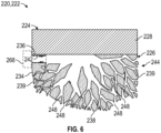
- the interface aperture 42 may be established along another portion of the implant 22. For example, the interface aperture may be established along an external surface of the augment body, as illustrated by interface aperture 242 of Figure 6 .
- the interface aperture 242 may be established along a sidewall 239 of the augment body 234 at a position between a front face 236 and a rear face 238 of the augment body 234.
- like reference numerals designate like elements where appropriate and reference numerals with the addition of one-hundred or multiples thereof designate modified elements that are understood to incorporate the same features and benefits of the corresponding original elements.
- the augment 26 may be dimensioned to approximate various defect geometries and surface contours that may be encountered along a surgical site S.
- a geometry of the augment 26 may be patient-specific based on one or more measurements of an anatomy of the patient.
- the rear face 38 of the augment 26 may be dimensioned to contact tissue such as bone B1 along the surgical site S.
- the rear face 38 may be dimensioned to overlay a surface contour SC along the bone B1, as illustrated in Figure 2A-2B .
- the augment 26 may be inlaid in the bone B1 to at least partially or completely fill a volume of a cavity C in the bone B1, and the baseplate 24 may be at least partially received in the cavity C, as illustrated in Figure 4 .
- the augment body 34 includes an internal network 44 for conveying blood, nutrients, bone marrow and other biological material to promote intraosseous integration of the implant 22 and healing of the patient.
- the biological material may be provided by the patient or from another source.
- the internal network 44 may be utilized to communicate other materials in the implant 22, including non-biological materials.
- Example non-biological materials may include a cement material to improve fixation, and antibiotics such as gentamicin to reduce the risk of infection at the bone-implant interface along the surgical site S, for example.
- the internal network 44 may be defined at least partially or completely within a thickness of the augment body 34 between the front face 36 and rear face 38.
- the internal network 44 has a predefined geometry dimensioned to establish a network of internal passages 46 coupled to respective ports 48 along the external surface of the augment body 34.
- predefined means an engineered construct that excludes random arrangements such as meshes and porous materials.
- the internal passages 46 may be dimensioned to establish respective flow paths between the interface aperture 42 and one or more of the respective ports 48.
- the internal passages 46 may be dimensioned to interconnect the interface aperture 42 and respective ports 48 along the external surface of the augment 26.
- One or more of the internal passages 46 may branch to the respective ports 48.
- the interface aperture 42 may be common to each of the internal passages 46 and ports 48, as illustrated in Figures 2A-2B .
- the implant 22 may include more than one interface aperture 42, each coupled to a respective set of internal passages 46.
- the network 44 may be dimensioned to branch outwardly from the rear face 32 of the plate body 28 and/or front face 36 of the augment body 34 to the ports 48 along opposed sidewalls 39 and/or rear face 38 of the augment body 34, as illustrated in Figures 2A-2B .
- the sidewalls 39 may have a substantially smooth and continuous profile to facilitate positioning of the augment 26 in the cavity C ( Figure 4 ).
- the interface aperture 42 may be defined along the plate body 28.
- the network 44 may include a main trunk 52 that extends outwardly from the interface aperture 42.
- the network 44 may be established such that one or more (or each) of the internal passages 46 is dimensioned to divide from the main trunk 52 into branched paths 54 coupled to respective ports 48.
- the internal passage 46 may divide into the branched paths 54 at a respective junction 50.
- At least two junctions 50 may be established between the interface aperture 42 and each of the respective ports 48, such that at least some of the internal passages 46 are branched paths 54 divided from another internal passage 46.
- the arrangement of internal passages 46 may reduce localized stress concentrations in the augment 26.
- network 44' includes at least three junctions 50' established between an interface aperture 42' and a respective one of the ports '48.
- the internal passage 46' may divide into at least two branched paths 54' at a respective junction 50', as illustrated in Figure 3A .
- a cross-sectional area of each internal passage 46' in the network 44' may be equal to or greater than a combined cross-sectional area of the branched paths 54' that divide from the internal passage 46' at the respective junction 50'.
- the internal passage 46' of Figure 3A may have a cross-sectional area of approximately 8 mm, and the two branched paths 54' may each have a cross-sectional area of approximately 4 mm at the junction 50' to yield a total cross-sectional area of approximately 8 mm.
- the cross-sectional area of the main trunk 52' may be equal to or greater than a summation of the cross-sectional areas of all of the downstream junctions 50' in the network 44'.
- the cross-sectional areas of the junctions 50' may decrease sequentially from the main trunk 52' in a direction D1.
- the network 44' may be predefined according to a Fibonacci sequence such that a cross-sectional area of each internal passages 46' progressively decreases in a series of the respective junctions 50' in the direction D1 from interface aperture 42' toward the respective ports 48', although an opposite arrangement may be utilized.
- the internal passages 46 including the branched paths 54 may be established in various orientations to communicate material throughout the internal network 44 including between the interface aperture 42 and ports 48.
- the internal network 44 may be dimensioned to generally mimic nature such as a root system of a tree.
- Portions of internal passages 46 may branch outwardly from the interface aperture 42 such that the portions of the internal passages 46 are radially offset from each other relative to the longitudinal axis A of the implant 22.
- Portions of the internal passage 46 may be established on opposed sides of an adjacent portion of the internal passage 46, as illustrated by branched paths 54 of the respective internal passages 46.
- Projections of the branched paths 54 may intersect each other on a common plane, as illustrated by Figure 2A , but may be radially offset from each other by a thickness of the augment body 34, as illustrated by Figure 2B taken along line 2B-2B of Figure 1 .
- the branched paths 54 may be coupled to respective ports 48 at different circumferential positions relative to the longitudinal axis A (see, e.g., Figure 1 ).
- the implant system 20 may include an articulation member 56 securable to the baseplate 24 adjacent the front face 30.
- the articulation member 56 may have an articulation surface 58.
- the articulation surface 58 may be configured to cooperate with the opposed articulation surface AS to establish a joint interface JI.
- the articulation member 56 may have various geometries that complement the articulation surface AS.
- the articulation member 56 may be an articulation head 60 having a generally convex articulation surface 58, as illustrated in Figure 4 .
- the articulation head 60 may be a glenosphere secured to a glenoid in a reverse shoulder repair procedure, for example.
- articulation member 156 includes a pad 164 having an articulation surface 158.
- the articulation surface 158 may have a generally concave geometry.
- the articulation member 156 may be utilized in a anatomic shoulder repair procedure, for example.
- the pad 164 may be securable to a baseplate 124 adjacent a front face 130.
- At least one peg 166 may extend outwardly from a body of the pad 164.
- the peg 166 may be dimensioned to be secured in a hole H1 in the bone B1 to provide fixation along the surgical site S.
- the pad 164 may include at least one protrusion 167 that is dimensioned to mate with the interface aperture 142 to limit relative movement between the baseplate 124 and pad 164.
- the articulation members 56, 156 may be mechanically attached or releasably secured to the respective baseplate 24, 124.
- the articulation members 56, 156 may include a respective recess 62, 162 dimensioned to at least partially receive the respective plate body 28, 128.
- a perimeter 62P/162P of the recess 62/162 may be dimensioned to encircle a perimeter 28P/128P of the plate body 28/128 adjacent the front face 30/130.
- the perimeter 28P/128P of the plate body 28/128 may be dimensioned to cooperate with the perimeter 62P/162P of the recess 62/162 to establish a Morse taper connection to secure the articulation member 56/156 to the baseplate 24/124.
- the articulation member 56/156 may be impacted or pressed on the baseplate 24/124 to establish an interference fit or otherwise seat the articulation member 56/156.
- the articulation head 60 may include an aperture 61 dimensioned to receive a respective fastener FF.
- the fastener FF may be at least partially received in the interface aperture 42 and cooperate with threading to mechanically attach the articulation head 60 to the baseplate 24 and assist in alignment of the articulation head 60.
- the articulation members 56, 156 may be provided together in a kit to the surgeon.
- the kit may include articulation members 56, 156 having different shapes and/or sizes for selection by the surgeon based on an anatomy of the patient.
- the implant system 20 may include a pump 68 selectively coupled to the implant 22 (shown in dashed lines for illustrative purposes, see also implant 222 of Figure 6 ).
- the pump 68 may be securable to the interface aperture 42 via a threaded connection, for example.
- the pump 68 may be configured to convey material through at least a portion of the internal network 44 in operation (see, e.g., pump 368 of Figure 12 ).
- the pump 68 may be configured to draw or otherwise communicate blood, bone marrow and other tissue, nutrients, other biological material and/or other material from the patient adjacent the surgical site S and at least partially into the internal network 44 to promote intraosseous integration of the implant 22 and healing of the patient, including any of the materials disclosed herein.
- the pump 68 may be configured to convey or deliver biological material from an external supply to the network 44, such as biological material from the patient or a donor gathered prior to placement of the implant 22.
- the implant 22 may be a monolithic arrangement in which the baseplate 24 and augment 26 may be integrally formed, or the implant 22 may be a modular arrangement that may include separate components that are mechanically attached or otherwise secured to each other.
- the augment 26 may be printed or otherwise formed on the baseplate 24 according to a predefined geometry to establish a three-dimensional scaffold.
- the scaffold establishes the internal network 44, which extends at least partially through a volume of the augment 26.
- the disclosed baseplates, augments and articulation members may be made of surgical grade metallic materials.
- Example metallic materials include titanium alloys such as Ti6Al4V and cobalt-based materials such as cobalt-chromium (CoCr).
- Non-metallic materials may be utilized, such as an ultrahigh-molecular-weight polyethylene (UHMWPE).
- UHMWPE ultrahigh-molecular-weight polyethylene
- the pad 164 ( Figure 5 ) may be made of a non-metallic material, including any of the non-metallic materials disclosed herein.
- Portions of the implant such as the augment may be constructed from a biological and other bio-materials, such hydroxyapatite and allograft bone or other tissue.
- the plate body of the baseplate may comprise a first material
- the augment body of the augment may comprise a second material.
- the first and second materials may be same or can differ in composition and/or construction. For example, a density of the first and second materials can be same or can differ.
- the plate body may be substantially solid.
- One or more coatings or layers may be deposited along surfaces of the implant, including the baseplate and/or augment.
- at least one layer 55' may be disposed along or otherwise establish surfaces of the augment body 34', as illustrated in Figure 3A .
- the implant 22' may include one or more layers(s) 55' that establish at least a majority or substantially all surfaces of the augment body 34' that define the network 44'.
- the layer(s) 55' may include any of the materials disclosed herein, including a non-biological material or a bioactive material or biologics that promote intraosseous integration of the implant 22' at the surgical site.
- Example layers may include calcium phosphate (CaP) and hydroxyapatite for promoting bone growth.
- the layer(s) 55' may be disposed on surfaces of the implant 22' concurrently or subsequent to formation of the implant 22'.
- the layer(s) 55' may be printed to establish surfaces of the internal network 44' while printing adjacent portions of the implant 22'.
- the layer(s) 55' may be deposited on surfaces of the augment body 34 to establish surfaces of the network 44'.
- the layer(s) 55' may be injected as a slurry into the network 44' subsequent to formation of the implant 22'.
- Figure 7 illustrates an exemplary method of installing an orthopaedic implant at a surgical site in a flowchart 380.
- the method may be utilized to perform an arthroplasty for restoring functionality to shoulders and other joints having advanced cartilage disease, such as repairing bone defects along a glenoid, for example.
- the method 380 primarily refers to implants for repair of a defect in a glenoid during a shoulder reconstruction, it should be understood that the method and disclosed implants may be utilized in other locations of the patient and other surgical procedures, such as the humerus or any other location disclosed herein.
- the method 380 can be utilized with any of the orthopedic implant systems disclosed herein. Fewer or additional steps than are recited below could be performed within the scope of this disclosure, and the recited order of steps is not intended to limit this disclosure.
- a kit for arthroplasty may be provided at step 380A.
- the kit may include any of the components of the implant systems disclosed herein.
- the kit may include a set of implants of various sizes and geometries.
- the surgeon may select one or more components from the kit.
- step 380B may include selecting an implant from a set of implants based on the planned surgical technique and/or an anatomy of the patient including a surface contour SC associated with a bone B1 along a surgical site S, as illustrated in Figure 8 .
- the surgical site S may be established along a glenoid G, for example.
- the kit may include fasteners of different sizes that may be received in respective apertures in the implant to secure the implant to the surgical site S.
- the kit may include articulation members of various sizes and geometries for securing to a selected implant. The surgeon may select an articulation member from the kit based on the planned surgical technique and/or the anatomy of the patient.
- the surgical site S can be prepared for receiving an implant 322 at step 380C.
- the implant 322 may correspond to any of the implants disclosed herein.
- the implant 322 can include a baseplate 324 and augment 326.
- One or more operations may be performed to prepare the surgical site S, such as one or more reaming, milling and/or drilling operations to establish a specified geometry of the surgical site S.
- Step 380C may include forming one or more holes in the surgical site dimensioned to receive respective fasteners (see, e.g., Figure 2B ).
- Step 380C may include forming a cavity C along the surgical site S, such as an articulating surface of the glenoid G, at step 380D.
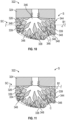
- the cavity C may be formed by removing a portion of the bone B1 or other tissue at the surgical site S, as illustrated in Figures 10 and 11 .
- the tissue may include cartilage, cancellous bone and/or cortical bone along the surgical site S.
- the cavity C may be dimensioned to at least partially or completely receive the baseplate 324 and/or augment 326.
- the cavity C may be formed to remove tissue from a defect in the bone B1 and may be dimensioned to approximate a profile of the defect.
- a defect in the glenoid can be characterized by the Walch Classification.
- the surgeon may measure bone loss utilizing imaging of the surgical site, such a radiogram or computed tomography technique, or may approximate a profile of the defect utilizing one or more sizers and/or measuring devices placed against the bone surface.
- the selected implant 322 may be positioned along the surgical site S at step 380E.
- Step 380E may occur such that the front face 330 of the baseplate 324 faces towards an opposed articular surface AS associated with an adjacent bone B2, as illustrated in Figure 13 .
- step 380E may include moving the implant 322 in a direction D2 ( Figure 8 ) such that the rear face 338 abuts against and overlays the surface contour SC of the bone B1, as illustrated in Figure 9 .
- the implant 322 is positioned such that at least the augment 326 abuts a surface and/or fills the cavity C along the surgical site S.
- step 380E may include positioning the augment 326 partially in the cavity C, as illustrated in Figure 10 , or positioning the augment 326 completely in the cavity C as illustrated in Figure 11 .
- Step 380E may include positioning at least a portion of the baseplate in the cavity, as illustrated by the baseplate 24 of Figure 4 .
- Step 380E may include moving the augment 326 at least partially into the cavity C such that an external surface of the augment body 334 abuts a wall of the cavity C adjacent the ports 348, as illustrated in Figures 10-11 .
- External walls of the augment body 334 may have a substantially smooth or continuous contour, including sidewalls 339.
- One or more ports 348 may be defined in the sidewalls 339 to promote communication of biological material M subsequent to placement of the implant 322 and completion of the surgical procedure.
- the augment body 334 may include one or more protrusions 370 extending outwardly from the rear face 338 or another portion of the augment body 334, as illustrated in Figure 9A .
- the protrusions 370 may be dimensioned to resemble one or more roots extending outwardly from the rear face 338.
- Each protrusion 370 may define at least one of the internal passages 346 and ports 348.
- Step 380E may include moving the implant 322 into abutment with a surface of the bone B1 such that the protrusions 370 are at least partially embedded in the bone B1, which may improve fixation of the implant 322 along the surgical site S.
- one or more fasteners may be positioned in and at least partially through a respective fastener aperture, and then into bone to secure the selected implant to the surgical site, as illustrated by the fasteners F of Figure 2B .
- the fasteners F may be compression screws that can serve to apply and maintain compression between the baseplate 24 and bone surface which may reduce relative motion and tissue formation that may otherwise occur due to spacing between the contact surfaces of the implant and bone.
- Abutment of the augment 326 against the adjacent bone B1 may establish a wicking or capillary action.
- the wicking action may cause biological material M from the surgical site S to at least partially or completely fill a volume of the internal network 344, which can promote bone growth and fixation of the implant 322.
- a pump 368 may be coupled to an internal network 344 of the implant 322 at step 380G.
- the pump 368 may include one or more modes.
- the pump 368 may be a bi-directional pump such as a syringe movable in a third direction D3 during a first mode and moveable in a fourth direction D4 during a second mode.
- the fourth direction D4 may be generally opposed to the third direction D3.
- the pump 368 may serve to draw biological material into the internal network 344 and/or move the biological material M toward the interface aperture 342 in the first mode.
- the pump 368 may serve to move biological material M away from the interface aperture 342 and through the internal network 344 in the second mode.
- the pump 368 may be actuated to cause biological and/or other material M to be communicated at least partially into the internal passages 346 of the internal network 344.
- Step 380H may include actuating the pump 368 in one or more modes, such as the first mode and/or second mode.
- the pump 368 may be actuated in the first mode to cause at least a portion of the biological material M to be drawn from the surgical site S, through the ports 348, and then at least partially into the internal passages 346 such that a volume of the internal network 344 is at least partially or substantially filled with the biological material M.
- the pump 368 may be actuated in the second mode to cause at least a portion of the biological material M in the network 344 to be pushed or otherwise move outwardly in a direction towards the ports 348.
- step 380I may include conveying non-biological material and/or biological material M from the pump 368 to the internal network 344, which may be provided by the patient or from another source.
- the pump 368 may be actuated in one or more cycles between the first and second modes to at least partially or substantially fill a volume of the internal network 344 with the non-biological material and/or biological material M.
- the pump 368 may be uncoupled from the interface aperture 342 of the implant 322 at step 380J.
- the interface aperture 342 may be utilized to obtain a visual indication of an amount of the biological material M that is contained in the internal network 344.
- the surgeon may repeat steps 380G, 380H, 380I and/or 380J until a determined portion of the internal network 344 is filled with the biological material M.
- a plug 372 may be positioned in the interface aperture 342 to at least partially seal the internal network 344 at step 380K (shown in dashed lines for illustrative purposes).
- the plug 372 may be made of any of the materials disclosed herein. In other implementations, the plug 372 is omitted. In some implementations, the fastener FF of Figure 4 may serve as a plug 72.
- An articulation member 356 may be secured to the baseplate 324 at step 380L.
- the articulation member 356 can include any of the articulation members disclosed herein.
- the articulation member 356 may be moved in a direction D5 and brought into abutment with the baseplate 324.
- the articulation member 356 may be secured to the plate body 328 adjacent to the front face 330.
- An articulation surface 358 of the articulation member 356 may be arranged to mate with an opposed articular surface AS.
- the articulation surface AS may be established by an adjacent bone B2 or by another implant situated along the adjacent bone B2.
- the adjacent bone B2 may be a humerus that opposes the glenoid G, for example.
- Example finishing operations may include closing an incision adjacent the surgical site S.
- the novel implants and methods of this disclosure can provide improved fixation and healing of the patient.
- the disclosed implants may include augments internal networks that receive biological material, which can improve intraosseous integration and fixation of the implant through the promotion of bone growth into the internal network.
- the disclosed internal networks including interconnected branches and nodes may emulate the structural, junctional and/or physiological properties of the native bone and improve force distribution to encourage structural adaption of the adjacent bone, which may improve fixation of the implant.
Landscapes
- Health & Medical Sciences (AREA)
- Engineering & Computer Science (AREA)
- Vascular Medicine (AREA)
- Life Sciences & Earth Sciences (AREA)
- Transplantation (AREA)
- Cardiology (AREA)
- Biomedical Technology (AREA)
- Heart & Thoracic Surgery (AREA)
- Orthopedic Medicine & Surgery (AREA)
- Oral & Maxillofacial Surgery (AREA)
- Animal Behavior & Ethology (AREA)
- General Health & Medical Sciences (AREA)
- Public Health (AREA)
- Veterinary Medicine (AREA)
- Manufacturing & Machinery (AREA)
- Prostheses (AREA)
- Surgical Instruments (AREA)
Description
- This disclosure relates to orthopaedic procedures and, more particularly, to orthopaedic implant systems for repairing bone defects and restoring functionality to a joint.
- Many bones of the human musculoskeletal system include articular surfaces. The articular surfaces articulate relative to other bones to facilitate different types and degrees of joint movement. The articular surfaces can erode or experience bone loss over time due to repeated use or wear or can fracture as a result of a traumatic impact. These types of bone defects can cause joint instability and pain.
- Bone deficiencies may occur along the articular surfaces. Some techniques utilize a bone graft and/or implant to repair a defect adjacent the articular surfaces. The implant may be secured to the bone utilizing one or more fasteners.
-
US 2013/0211539 A1 discloses a negative-positive pressurizable implant.EP 3 763 335 A1 discloses a joint implant for the administration of a drug.US 5,116,377 discloses a cementable hip prosthesis.US 2006/0015188 A1 discloses a prosthesis and method of implantation. - This disclosure relates to orthopaedic implant systems that may be used during methods for repairing bone defects. The implant systems described herein may be utilized to restore functionality to a joint and include implants having an internal network for communicating various materials in the respective implant.
- An orthopaedic implant system according to the present invention is defined in claim 1.
- A method of installing an orthopaedic implant system of the present disclosure may include positioning an implant along a surgical site.
- The positioning step may occur such that the front face of the baseplate faces towards an opposed articular surface associated with an adjacent bone.
- The various features and advantages of this disclosure will become apparent to those skilled in the art from the following detailed description. The drawings that accompany the detailed description can be briefly described as follows.
-
-
Figure 1 illustrates a perspective view of an exemplary orthopaedic implant of an implant system including a baseplate and augment. -
Figures 2A-2B illustrate sectional views of the implant taken alonglines 2A-2A and 2B-2B ofFigure 1 . -
Figures 3-3A illustrate an example network of internal passages. -
Figures 5 illustrates a sectional view of the implant ofFigure 1 coupled to an exemplary articulation member. -
Figure 5 illustrates another sectional view of the implant ofFigure 1 coupled to an exemplary articulation member. -
Figure 6 illustrates a sectional view of another exemplary implant system. -
Figure 7 illustrates an exemplary method of installing an orthopaedic implant. -
Figures 8-9, 9A and10-13 illustrates an exemplary implant system in various modes, positions and states relative to a surgical site. - Like reference numbers and designations in the various drawings indicate like elements.
- This disclosure relates to orthopaedic implant systems and methods for repairing bone defects. The implant systems described herein may be utilized during arthroplasty procedures and may include implants incorporated into a prosthesis for restoring functionality to shoulders and other joints having advanced cartilage disease. The implants include an augment that extends from a respective baseplate. The implants may be situated along a surgical site such as the glenoid face to at least partially fill a bone void. The augment includes an internal network for communicating biological and/or other material in the respective implant, which may improve fixation and healing of the patient.
- An orthopaedic implant system according to an exemplary aspect of the present disclosure includes an implant including a baseplate and an augment. The baseplate includes a plate body extending between front and rear faces. The front face is configured to face towards an opposed articular surface associated with a bone. The augment includes an augment body extending from the rear face of the plate body. The augment body includes a network of internal passages that branch to respective ports along an external surface of the augment body.
- In some embodiments, the network may be dimensioned to branch outwardly from the rear face of the plate body to opposed sidewalls of the augment body.
- In some embodiments, the internal passages may interconnect the respective ports and a common interface aperture defined along an external surface of the implant.
- In some embodiments, each of the internal passages may divide into branched paths at a respective junction. At least two of the junctions may be established between the common interface aperture and each of the respective ports.
- In some embodiments, the network may be arranged according to a Fibonacci sequence such that a cross sectional area of the internal passages may progressively decrease at each of the respective junctions in a direction towards the respective ports.
- In some embodiments, the implant system may include a pump securable to the common interface aperture. The pump may be configured to draw biological material from the ports at least partially into the internal passages.
- In some embodiments, the common interface aperture may be defined along the plate body. The network may include a main trunk that extends outwardly from the common interface aperture. The internal passages may divide from the main trunk into branched paths coupled to the respective ports.
- In some embodiments, the implant system may include a pad including a concave articulation surface. The pad may be securable to the baseplate adjacent the front face.
- In some embodiments, the implant system may include an articulation head including a convex articulation surface. The articulation head may be securable to the baseplate adjacent the front face.
- In some embodiments, the articulation head may include a recess dimensioned to at least partially receive the plate body.
- According to the invention, the implant includes at least one fixation aperture extending at least partially through the plate body and the augment body. The at least one fixation aperture is configured to receive a respective fastener to secure the implant to bone.
- In some embodiments, the implant may include one or more bioactive layers that establish at least a majority of surfaces of the augment body that define the network.
- An orthopaedic implant system according to an exemplary aspect of the present disclosure may include a pump configured to communicate biological material at least partially into the network.
- In some embodiments, the implant system may include an interface aperture defined along an external surface of the implant. The internal passages may interconnect the respective ports and the interface aperture. The pump may be securable to the implant at the interface aperture.
- In some embodiments, the implant system may include an articulation member including an articulation surface that may be configured to cooperate with the opposed articular surface to establish a joint interface. The articulation member may be securable to the baseplate.
- In some embodiments, the implant system may include a plurality of fasteners. The implant may include a plurality of fixation apertures. Each of the fixation apertures may be configured to receive a respective one of the fasteners to secure the implant to bone.
- A method of installing an orthopaedic implant system may include positioning an implant along a surgical site. The positioning step may occur such that the front face of the baseplate faces towards an opposed articular surface associated with an adjacent bone.
- The method may include coupling a pump to the network and actuating the pump to cause biological material to be communicated at least partially into the internal passages.
- The method may include actuating the pump in a first mode to cause at least a portion of the biological material to be drawn from surgical site, through the ports, and then at least partially into the internal passages.
- The method may include actuating the pump in a second mode to cause at least a portion of the biological material in the network to move outwardly in a direction towards the ports.
- The network may branch outwardly from the rear face of the plate body to the ports.
- The method may include forming a cavity in bone along the surgical site. The step of positioning the implant may include moving the augment at least partially into the cavity such that the external surface of the augment body abuts a wall of the cavity adjacent the ports.
- The implant includes a fixation aperture. The method may include positioning a fastener at least partially through the fixation aperture and into bone to secure the implant to the surgical site.
- The method may include securing an articulation member to the plate body adjacent to the front face. The articulation member may include an articulation surface that cooperates with the opposed articular surface to establish a joint interface.
- The surgical site may be established along a glenoid.
-
Figure 1 illustrates an exemplaryorthopedic implant system 20 including animplant 22 securable to a surgical site. Thesystem 20 may be utilized for various surgical procedures, such as an arthroplasty to repair a joint. Theimplant 22 may be incorporated into a shoulder prosthesis, for example. Although the implants disclosed herein primarily refer to repair of a defect in a glenoid during a shoulder reconstruction, such as an anatomic or reverse shoulder procedure, it should be understood that the disclosed implants may be utilized in other locations of the patient and other surgical procedures including repair of a humerus and other joints such as a wrist, hand, hip, knee, ankle or spline, and including repair of fractures. - The
implant 22 includes abaseplate 24 and augment 26. Thebaseplate 24 includes aplate body 28 extending along a central axis A between afront face 30 and arear face 32 generally opposed to thefront face 30. Thefront face 30 is configured to face toward an opposed articulation surface AS associated with an adjacent bone B2, as illustrated inFigure 4 . The articulation surface AS may be a portion of the bone B2 or an adjacent implant component secured to the bone B2. - The
baseplate 24 may have various geometries. A perimeter of thebaseplate 24 may have as a generally rectangular, elliptical, oval, oblong or complex geometry. For example, aperimeter 28P of theplate body 28 may have a substantially circular or elliptical cross-sectional geometry, as illustrated inFigure 1 . For the purposes of this disclosure, the terms "substantially" and "approximately" mean ±5% of the stated relationship or value unless otherwise stated. A substantially circular geometry may reduce a reaming width and complexity of preparing a surgical site to accept theimplant 22. - The augment 26 includes an augment
body 34 extending between afront face 36 and arear face 38 generally opposed to thefront face 36. The augmentbody 34 is disposed on and extends from therear face 32 of theplate body 28 along the central axis A. The rear faces 32, 38 of thebaseplate 24 and augment 26 may generally correspond to a medial side of a patient, and the front faces 30, 36 of thebaseplate 24 and augment 26 may generally correspond to a lateral side of the patient when implanted in a surgical site, for example. - The
implant 22 includes one ormore fixation apertures 40. Eachfixation aperture 40 extends at least partially or completely through theplate body 28 and/or augmentbody 34, as illustrated inFigure 2B . Eachfixation aperture 40 is configured to receive a respective fastener F to secure theimplant 22 to tissue such as bone B1, as illustrated inFigure 2B (B1 and F shown in dashed lines for illustrative purposes). Thesystem 20 may include a plurality of fasteners F received inrespective fixation apertures 40, as illustrated inFigure 1 . Example fasteners may include pins, nails, bolts and compression screws. - The
implant 22 may include at least oneinterface aperture 42 defined along an external surface of theimplant 22. Theinterface aperture 42 may extend along the central axis A between thefront face 30 andrear face 32 of theplate body 28, as illustrated inFigures 2A-2B . The fixation apertures 40 may be distributed in an array about theinterface aperture 42 and/or central axis A, as illustrated inFigure 1 . Theinterface aperture 42 may also serve as a fixation aperture. Theinterface aperture 42 may be established along another portion of theimplant 22. For example, the interface aperture may be established along an external surface of the augment body, as illustrated byinterface aperture 242 ofFigure 6 . Theinterface aperture 242 may be established along asidewall 239 of the augmentbody 234 at a position between afront face 236 and arear face 238 of the augmentbody 234. In this disclosure, like reference numerals designate like elements where appropriate and reference numerals with the addition of one-hundred or multiples thereof designate modified elements that are understood to incorporate the same features and benefits of the corresponding original elements. - Referring to
Figure 2A , with continuing reference toFigure 1 , the augment 26 may be dimensioned to approximate various defect geometries and surface contours that may be encountered along a surgical site S. In some implementations, a geometry of the augment 26 may be patient-specific based on one or more measurements of an anatomy of the patient. Therear face 38 of the augment 26 may be dimensioned to contact tissue such as bone B1 along the surgical site S. Therear face 38 may be dimensioned to overlay a surface contour SC along the bone B1, as illustrated inFigure 2A-2B . In other implementations, the augment 26 may be inlaid in the bone B1 to at least partially or completely fill a volume of a cavity C in the bone B1, and thebaseplate 24 may be at least partially received in the cavity C, as illustrated inFigure 4 . - The augment
body 34 includes aninternal network 44 for conveying blood, nutrients, bone marrow and other biological material to promote intraosseous integration of theimplant 22 and healing of the patient. The biological material may be provided by the patient or from another source. Theinternal network 44 may be utilized to communicate other materials in theimplant 22, including non-biological materials. Example non-biological materials may include a cement material to improve fixation, and antibiotics such as gentamicin to reduce the risk of infection at the bone-implant interface along the surgical site S, for example. - The
internal network 44 may be defined at least partially or completely within a thickness of the augmentbody 34 between thefront face 36 andrear face 38. Theinternal network 44 has a predefined geometry dimensioned to establish a network ofinternal passages 46 coupled torespective ports 48 along the external surface of the augmentbody 34. For purposes of this disclosure, the term "predefined" means an engineered construct that excludes random arrangements such as meshes and porous materials. - The
internal passages 46 may be dimensioned to establish respective flow paths between theinterface aperture 42 and one or more of therespective ports 48. Theinternal passages 46 may be dimensioned to interconnect theinterface aperture 42 andrespective ports 48 along the external surface of the augment 26. One or more of theinternal passages 46 may branch to therespective ports 48. - The
interface aperture 42 may be common to each of theinternal passages 46 andports 48, as illustrated inFigures 2A-2B . In other examples, theimplant 22 may include more than oneinterface aperture 42, each coupled to a respective set ofinternal passages 46. Thenetwork 44 may be dimensioned to branch outwardly from therear face 32 of theplate body 28 and/orfront face 36 of the augmentbody 34 to theports 48 along opposed sidewalls 39 and/orrear face 38 of the augmentbody 34, as illustrated inFigures 2A-2B . Thesidewalls 39 may have a substantially smooth and continuous profile to facilitate positioning of the augment 26 in the cavity C (Figure 4 ). - The
interface aperture 42 may be defined along theplate body 28. Thenetwork 44 may include amain trunk 52 that extends outwardly from theinterface aperture 42. Thenetwork 44 may be established such that one or more (or each) of theinternal passages 46 is dimensioned to divide from themain trunk 52 into branchedpaths 54 coupled torespective ports 48. Theinternal passage 46 may divide into the branchedpaths 54 at arespective junction 50. At least twojunctions 50 may be established between theinterface aperture 42 and each of therespective ports 48, such that at least some of theinternal passages 46 are branchedpaths 54 divided from anotherinternal passage 46. The arrangement ofinternal passages 46 may reduce localized stress concentrations in the augment 26. - In the illustrative example of
Figure 3 , network 44' includes at least three junctions 50' established between an interface aperture 42' and a respective one of the ports '48. The internal passage 46' may divide into at least two branched paths 54' at a respective junction 50', as illustrated inFigure 3A . A cross-sectional area of each internal passage 46' in the network 44' may be equal to or greater than a combined cross-sectional area of the branched paths 54' that divide from the internal passage 46' at the respective junction 50'. For example, the internal passage 46' ofFigure 3A may have a cross-sectional area of approximately 8 mm, and the two branched paths 54' may each have a cross-sectional area of approximately 4 mm at the junction 50' to yield a total cross-sectional area of approximately 8 mm. The cross-sectional area of the main trunk 52' may be equal to or greater than a summation of the cross-sectional areas of all of the downstream junctions 50' in the network 44'. The cross-sectional areas of the junctions 50' may decrease sequentially from the main trunk 52' in a direction D1. For example, the network 44' may be predefined according to a Fibonacci sequence such that a cross-sectional area of each internal passages 46' progressively decreases in a series of the respective junctions 50' in the direction D1 from interface aperture 42' toward the respective ports 48', although an opposite arrangement may be utilized. - The
internal passages 46 including the branchedpaths 54 may be established in various orientations to communicate material throughout theinternal network 44 including between theinterface aperture 42 andports 48. In implementations, theinternal network 44 may be dimensioned to generally mimic nature such as a root system of a tree. Portions ofinternal passages 46 may branch outwardly from theinterface aperture 42 such that the portions of theinternal passages 46 are radially offset from each other relative to the longitudinal axis A of theimplant 22. Portions of theinternal passage 46 may be established on opposed sides of an adjacent portion of theinternal passage 46, as illustrated bybranched paths 54 of the respectiveinternal passages 46. Projections of the branchedpaths 54 may intersect each other on a common plane, as illustrated byFigure 2A , but may be radially offset from each other by a thickness of the augmentbody 34, as illustrated byFigure 2B taken alongline 2B-2B ofFigure 1 . The branchedpaths 54 may be coupled torespective ports 48 at different circumferential positions relative to the longitudinal axis A (see, e.g.,Figure 1 ). - Referring to
Figure 4 , theimplant system 20 may include anarticulation member 56 securable to thebaseplate 24 adjacent thefront face 30. Thearticulation member 56 may have anarticulation surface 58. Thearticulation surface 58 may be configured to cooperate with the opposed articulation surface AS to establish a joint interface JI. - The
articulation member 56 may have various geometries that complement the articulation surface AS. For example, thearticulation member 56 may be anarticulation head 60 having a generallyconvex articulation surface 58, as illustrated inFigure 4 . Thearticulation head 60 may be a glenosphere secured to a glenoid in a reverse shoulder repair procedure, for example. - The articulation member may have other geometries. As illustrated by implant 122 of
Figure 5 ,articulation member 156 includes apad 164 having an articulation surface 158. The articulation surface 158 may have a generally concave geometry. Thearticulation member 156 may be utilized in a anatomic shoulder repair procedure, for example. Thepad 164 may be securable to abaseplate 124 adjacent a front face 130. At least onepeg 166 may extend outwardly from a body of thepad 164. Thepeg 166 may be dimensioned to be secured in a hole H1 in the bone B1 to provide fixation along the surgical site S. Thepad 164 may include at least oneprotrusion 167 that is dimensioned to mate with theinterface aperture 142 to limit relative movement between thebaseplate 124 andpad 164. - Various techniques may be utilized to secure the
articulation members respective baseplates 22, 122. Thearticulation members respective baseplate Figures 4 and 5 , thearticulation members respective recess 62, 162 dimensioned to at least partially receive therespective plate body perimeter 62P/162P of therecess 62/162 may be dimensioned to encircle aperimeter 28P/128P of theplate body 28/128 adjacent thefront face 30/130. Theperimeter 28P/128P of theplate body 28/128 may be dimensioned to cooperate with theperimeter 62P/162P of therecess 62/162 to establish a Morse taper connection to secure thearticulation member 56/156 to thebaseplate 24/124. Thearticulation member 56/156 may be impacted or pressed on thebaseplate 24/124 to establish an interference fit or otherwise seat thearticulation member 56/156. Thearticulation head 60 may include anaperture 61 dimensioned to receive a respective fastener FF. The fastener FF may be at least partially received in theinterface aperture 42 and cooperate with threading to mechanically attach thearticulation head 60 to thebaseplate 24 and assist in alignment of thearticulation head 60. - The
articulation members articulation members - Referring back to
Figure 2A , theimplant system 20 may include apump 68 selectively coupled to the implant 22 (shown in dashed lines for illustrative purposes, see also implant 222 ofFigure 6 ). Thepump 68 may be securable to theinterface aperture 42 via a threaded connection, for example. Thepump 68 may be configured to convey material through at least a portion of theinternal network 44 in operation (see, e.g., pump 368 ofFigure 12 ). Thepump 68 may be configured to draw or otherwise communicate blood, bone marrow and other tissue, nutrients, other biological material and/or other material from the patient adjacent the surgical site S and at least partially into theinternal network 44 to promote intraosseous integration of theimplant 22 and healing of the patient, including any of the materials disclosed herein. In implementations, thepump 68 may be configured to convey or deliver biological material from an external supply to thenetwork 44, such as biological material from the patient or a donor gathered prior to placement of theimplant 22. - Various techniques may be utilized to form the
implant 22. Theimplant 22 may be a monolithic arrangement in which thebaseplate 24 and augment 26 may be integrally formed, or theimplant 22 may be a modular arrangement that may include separate components that are mechanically attached or otherwise secured to each other. The augment 26 may be printed or otherwise formed on thebaseplate 24 according to a predefined geometry to establish a three-dimensional scaffold. The scaffold establishes theinternal network 44, which extends at least partially through a volume of the augment 26. - Various materials may be utilized to form the components of the implant systems disclosed herein. The disclosed baseplates, augments and articulation members may be made of surgical grade metallic materials. Example metallic materials include titanium alloys such as Ti6Al4V and cobalt-based materials such as cobalt-chromium (CoCr). Non-metallic materials may be utilized, such as an ultrahigh-molecular-weight polyethylene (UHMWPE). The pad 164 (
Figure 5 ) may be made of a non-metallic material, including any of the non-metallic materials disclosed herein. Portions of the implant such as the augment may be constructed from a biological and other bio-materials, such hydroxyapatite and allograft bone or other tissue. - The plate body of the baseplate may comprise a first material, and the augment body of the augment may comprise a second material. The first and second materials may be same or can differ in composition and/or construction. For example, a density of the first and second materials can be same or can differ. The plate body may be substantially solid.
- One or more coatings or layers may be deposited along surfaces of the implant, including the baseplate and/or augment. For example, at least one layer 55' may be disposed along or otherwise establish surfaces of the augment body 34', as illustrated in
Figure 3A . The implant 22' may include one or more layers(s) 55' that establish at least a majority or substantially all surfaces of the augment body 34' that define the network 44'. The layer(s) 55' may include any of the materials disclosed herein, including a non-biological material or a bioactive material or biologics that promote intraosseous integration of the implant 22' at the surgical site. Example layers may include calcium phosphate (CaP) and hydroxyapatite for promoting bone growth. The layer(s) 55' may be disposed on surfaces of the implant 22' concurrently or subsequent to formation of the implant 22'. For example, the layer(s) 55' may be printed to establish surfaces of the internal network 44' while printing adjacent portions of the implant 22'. In other implementations, the layer(s) 55' may be deposited on surfaces of the augmentbody 34 to establish surfaces of the network 44'. For example, the layer(s) 55' may be injected as a slurry into the network 44' subsequent to formation of the implant 22'. -
Figure 7 illustrates an exemplary method of installing an orthopaedic implant at a surgical site in aflowchart 380. The method may be utilized to perform an arthroplasty for restoring functionality to shoulders and other joints having advanced cartilage disease, such as repairing bone defects along a glenoid, for example. Although themethod 380 primarily refers to implants for repair of a defect in a glenoid during a shoulder reconstruction, it should be understood that the method and disclosed implants may be utilized in other locations of the patient and other surgical procedures, such as the humerus or any other location disclosed herein. Themethod 380 can be utilized with any of the orthopedic implant systems disclosed herein. Fewer or additional steps than are recited below could be performed within the scope of this disclosure, and the recited order of steps is not intended to limit this disclosure. - A kit for arthroplasty may be provided at
step 380A. The kit may include any of the components of the implant systems disclosed herein. The kit may include a set of implants of various sizes and geometries. Atstep 380B the surgeon may select one or more components from the kit. For example,step 380B may include selecting an implant from a set of implants based on the planned surgical technique and/or an anatomy of the patient including a surface contour SC associated with a bone B1 along a surgical site S, as illustrated inFigure 8 . The surgical site S may be established along a glenoid G, for example. The kit may include fasteners of different sizes that may be received in respective apertures in the implant to secure the implant to the surgical site S. The kit may include articulation members of various sizes and geometries for securing to a selected implant. The surgeon may select an articulation member from the kit based on the planned surgical technique and/or the anatomy of the patient. - Referring to
Figure 8 , with continuing reference toFigure 7 , the surgical site S can be prepared for receiving animplant 322 atstep 380C. Theimplant 322 may correspond to any of the implants disclosed herein. Theimplant 322 can include abaseplate 324 and augment 326. One or more operations may be performed to prepare the surgical site S, such as one or more reaming, milling and/or drilling operations to establish a specified geometry of the surgicalsite S. Step 380C may include forming one or more holes in the surgical site dimensioned to receive respective fasteners (see, e.g.,Figure 2B ). -
Step 380C may include forming a cavity C along the surgical site S, such as an articulating surface of the glenoid G, atstep 380D. The cavity C may be formed by removing a portion of the bone B1 or other tissue at the surgical site S, as illustrated inFigures 10 and 11 . The tissue may include cartilage, cancellous bone and/or cortical bone along the surgical site S. - The cavity C may be dimensioned to at least partially or completely receive the
baseplate 324 and/or augment 326. The cavity C may be formed to remove tissue from a defect in the bone B1 and may be dimensioned to approximate a profile of the defect. A defect in the glenoid can be characterized by the Walch Classification. The surgeon may measure bone loss utilizing imaging of the surgical site, such a radiogram or computed tomography technique, or may approximate a profile of the defect utilizing one or more sizers and/or measuring devices placed against the bone surface. - The selected
implant 322 may be positioned along the surgical site S atstep 380E.Step 380E may occur such that thefront face 330 of thebaseplate 324 faces towards an opposed articular surface AS associated with an adjacent bone B2, as illustrated inFigure 13 . - Referring to
Figures 8 and 9 , with continuing reference toFigure 7 ,step 380E may include moving theimplant 322 in a direction D2 (Figure 8 ) such that therear face 338 abuts against and overlays the surface contour SC of the bone B1, as illustrated inFigure 9 . In some implementations, theimplant 322 is positioned such that at least the augment 326 abuts a surface and/or fills the cavity C along the surgical site S. For example,step 380E may include positioning the augment 326 partially in the cavity C, as illustrated inFigure 10 , or positioning the augment 326 completely in the cavity C as illustrated inFigure 11 .Step 380E may include positioning at least a portion of the baseplate in the cavity, as illustrated by thebaseplate 24 ofFigure 4 . -
Step 380E may include moving the augment 326 at least partially into the cavity C such that an external surface of the augmentbody 334 abuts a wall of the cavity C adjacent theports 348, as illustrated inFigures 10-11 . External walls of the augmentbody 334 may have a substantially smooth or continuous contour, includingsidewalls 339. One ormore ports 348 may be defined in thesidewalls 339 to promote communication of biological material M subsequent to placement of theimplant 322 and completion of the surgical procedure. - In some implementations, the augment
body 334 may include one ormore protrusions 370 extending outwardly from therear face 338 or another portion of the augmentbody 334, as illustrated inFigure 9A . Theprotrusions 370 may be dimensioned to resemble one or more roots extending outwardly from therear face 338. Eachprotrusion 370 may define at least one of theinternal passages 346 andports 348.Step 380E may include moving theimplant 322 into abutment with a surface of the bone B1 such that theprotrusions 370 are at least partially embedded in the bone B1, which may improve fixation of theimplant 322 along the surgical site S. - At
step 380F, one or more fasteners may be positioned in and at least partially through a respective fastener aperture, and then into bone to secure the selected implant to the surgical site, as illustrated by the fasteners F ofFigure 2B . The fasteners F may be compression screws that can serve to apply and maintain compression between thebaseplate 24 and bone surface which may reduce relative motion and tissue formation that may otherwise occur due to spacing between the contact surfaces of the implant and bone. - Abutment of the augment 326 against the adjacent bone B1 may establish a wicking or capillary action. The wicking action may cause biological material M from the surgical site S to at least partially or completely fill a volume of the
internal network 344, which can promote bone growth and fixation of theimplant 322. - Referring to
Figure 12 , with continuing reference toFigure 7 , in some implementations apump 368 may be coupled to aninternal network 344 of theimplant 322 atstep 380G. Thepump 368 may include one or more modes. For example, thepump 368 may be a bi-directional pump such as a syringe movable in a third direction D3 during a first mode and moveable in a fourth direction D4 during a second mode. The fourth direction D4 may be generally opposed to the third direction D3. Thepump 368 may serve to draw biological material into theinternal network 344 and/or move the biological material M toward theinterface aperture 342 in the first mode. Thepump 368 may serve to move biological material M away from theinterface aperture 342 and through theinternal network 344 in the second mode. - At
step 380H, thepump 368 may be actuated to cause biological and/or other material M to be communicated at least partially into theinternal passages 346 of theinternal network 344.Step 380H may include actuating thepump 368 in one or more modes, such as the first mode and/or second mode. Atstep 380H, thepump 368 may be actuated in the first mode to cause at least a portion of the biological material M to be drawn from the surgical site S, through theports 348, and then at least partially into theinternal passages 346 such that a volume of theinternal network 344 is at least partially or substantially filled with the biological material M. Atstep 3801, thepump 368 may be actuated in the second mode to cause at least a portion of the biological material M in thenetwork 344 to be pushed or otherwise move outwardly in a direction towards theports 348. In some implementations, step 380I may include conveying non-biological material and/or biological material M from thepump 368 to theinternal network 344, which may be provided by the patient or from another source. Thepump 368 may be actuated in one or more cycles between the first and second modes to at least partially or substantially fill a volume of theinternal network 344 with the non-biological material and/or biological material M. Thepump 368 may be uncoupled from theinterface aperture 342 of theimplant 322 atstep 380J. - The
interface aperture 342 may be utilized to obtain a visual indication of an amount of the biological material M that is contained in theinternal network 344. The surgeon may repeatsteps internal network 344 is filled with the biological material M. - Referring to
Figure 13 , with continuing reference toFigure 7 , aplug 372 may be positioned in theinterface aperture 342 to at least partially seal theinternal network 344 atstep 380K (shown in dashed lines for illustrative purposes). Theplug 372 may be made of any of the materials disclosed herein. In other implementations, theplug 372 is omitted. In some implementations, the fastener FF ofFigure 4 may serve as aplug 72. - An
articulation member 356 may be secured to thebaseplate 324 atstep 380L. Thearticulation member 356 can include any of the articulation members disclosed herein. Thearticulation member 356 may be moved in a direction D5 and brought into abutment with thebaseplate 324. Thearticulation member 356 may be secured to theplate body 328 adjacent to thefront face 330. Anarticulation surface 358 of thearticulation member 356 may be arranged to mate with an opposed articular surface AS. The articulation surface AS may be established by an adjacent bone B2 or by another implant situated along the adjacent bone B2. The adjacent bone B2 may be a humerus that opposes the glenoid G, for example. - One or more subsequent and/or finishing operations may be performed at
step 380M. Example finishing operations may include closing an incision adjacent the surgical site S. - The novel implants and methods of this disclosure can provide improved fixation and healing of the patient. The disclosed implants may include augments internal networks that receive biological material, which can improve intraosseous integration and fixation of the implant through the promotion of bone growth into the internal network. The disclosed internal networks including interconnected branches and nodes may emulate the structural, junctional and/or physiological properties of the native bone and improve force distribution to encourage structural adaption of the adjacent bone, which may improve fixation of the implant.
- Although the different non-limiting embodiments are illustrated as having specific components or steps, the embodiments of this disclosure are not limited to those particular combinations. It is possible to use some of the components or features from any of the non-limiting embodiments in combination with features or components from any of the other non-limiting embodiments.
- The foregoing description shall be interpreted as illustrative and not in any limiting sense. A worker of ordinary skill in the art would understand that certain modifications could come within the scope of this disclosure. For these reasons, the following claims should be studied to determine the true scope and content of this disclosure.
Claims (14)
- An orthopaedic implant system (20) comprising:an implant (22) including a baseplate (24) and an augment (26);wherein the baseplate (24) includes a plate body (28) extending between front and rear faces (30, 32), and the front face (30) is configured to face towards an opposed articular surface associated with a bone; and
wherein the augment (26) includes an augment body (34) extending from the rear face (32) of the plate body (28), and the augment body (34) includes a network (44) of internal passages (46) that branch to respective ports (48) along an external surface of the augment body (34),characterized in thatthe implant (22) includes at least one fixation aperture (40) extending at least partially through the plate body (28) and the augment body (34); andthe at least one fixation aperture (40) is configured to receive a respective fastener to secure the implant (22) to bone. - The system (20) as recited in claim 1, wherein the network (44) is dimensioned to branch outwardly from the rear face (32) of the plate body (28) to opposed sidewalls (39) of the augment body (34).
- The system (20) as recited in claim 1, wherein the internal passages (46) interconnect the respective ports (48) and a common interface aperture (42) defined along an external surface of the implant (22).
- The system (20) as recited in claim 3, wherein each of the internal passages (46) divides into branched paths (54) at a respective junction (50), and at least two of the junctions (50) are established between the common interface aperture (42) and each of the respective ports (48).
- The system (20) as recited in claim 4, wherein the network (44) is arranged according to a Fibonacci sequence such that a cross sectional area of the internal passages (46) progressively decreases at each of the respective junctions (50) in a direction towards the respective ports (48).
- The system (20) as recited in claim 3, further comprising:a pump securable to the common interface aperture (42); andwherein the pump is configured to draw biological material from the ports (48) at least partially into the internal passages (46).
- The system (20) as recited in claim 6, wherein:the common interface aperture (42) is defined along the plate body (28); andthe network (44) includes a main trunk (52) that extends outwardly from the common interface aperture (42), and the internal passages (46) divide from the main trunk (52) into branched paths (54) coupled to the respective ports (48).
- The system (20) as recited in claim 1, further comprising:a pad including a concave articulation surface (58); andwherein the pad is securable to the baseplate (24) adjacent the front face.
- The system (20) as recited in claim 1, further comprising:an articulation head (60) including a convex articulation surface (58); andwherein the articulation head (60) is securable to the baseplate (24) adjacent the front face, andwherein the articulation head (60) may include a recess (62) dimensioned to at least partially receive the plate body (28).
- The system (20) as recited in claim 1, further comprising:
one or more bioactive layers that establish at least a majority of surfaces of the augment body (34) that define the network (44). - The system (20) as recited in claim 1, further comprising:
a pump configured to communicate biological material at least partially into the network (44). - The system (20) as recited in claim 11, wherein:the implant (22) includes an interface aperture (42) defined along an external surface of the implant (22), and the internal passages (46) interconnect the respective ports (48) and the interface aperture (42); andthe pump is securable to the implant (22) at the interface aperture (42).
- The system (20) as recited in claim 11, further comprising:an articulation member (56) including an articulation surface (58) that is configured to cooperate with the opposed articular surface to establish a joint interface; andwherein the articulation member (56) is securable to the baseplate (24).
- The system (20) as recited in claim 11, further comprising:a plurality of fasteners; andwherein the implant (22) includes a plurality of fixation apertures (40), and each of the fixation apertures (40) is configured to receive a respective one of the fasteners to secure the implant (22) to bone.
Applications Claiming Priority (2)
| Application Number | Priority Date | Filing Date | Title |
|---|---|---|---|
| US17/221,049 US11819415B2 (en) | 2021-04-02 | 2021-04-02 | Orthopaedic implant systems including internal networks and methods of repair |
| PCT/US2022/020681 WO2022212071A1 (en) | 2021-04-02 | 2022-03-17 | Orthopaedic implant systems including internal networks and methods of repair |
Publications (3)
| Publication Number | Publication Date |
|---|---|
| EP4312886A1 EP4312886A1 (en) | 2024-02-07 |
| EP4312886C0 EP4312886C0 (en) | 2024-09-25 |
| EP4312886B1 true EP4312886B1 (en) | 2024-09-25 |
Family
ID=81326574
Family Applications (1)
| Application Number | Title | Priority Date | Filing Date |
|---|---|---|---|
| EP22715263.4A Active EP4312886B1 (en) | 2021-04-02 | 2022-03-17 | Orthopaedic implant systems including internal networks |
Country Status (6)
| Country | Link |
|---|---|
| US (2) | US11819415B2 (en) |
| EP (1) | EP4312886B1 (en) |
| JP (1) | JP7625720B2 (en) |
| CN (1) | CN117320671A (en) |
| CA (1) | CA3214219A1 (en) |
| WO (1) | WO2022212071A1 (en) |
Families Citing this family (13)
| Publication number | Priority date | Publication date | Assignee | Title |
|---|---|---|---|---|
| FR2971144A1 (en) * | 2011-02-08 | 2012-08-10 | Tornier Sa | GLENOIDAL IMPLANT FOR SHOULDER PROSTHESIS AND SURGICAL KIT |
| EP3628245B1 (en) | 2013-10-10 | 2025-01-29 | Stryker European Operations Limited | Method for designing and producing a shoulder surgery guide |
| WO2015068035A1 (en) | 2013-11-08 | 2015-05-14 | Imascap | Methods, systems and devices for pre-operatively planned adaptive glenoid implants |
| EP3068317B1 (en) | 2013-11-13 | 2018-08-22 | Tornier | Shoulder patient specific instrument |
| EP3777777B1 (en) | 2014-01-03 | 2023-04-05 | Howmedica Osteonics Corp. | Glenoid implant for a shoulder prosthesis |
| US10722374B2 (en) | 2015-05-05 | 2020-07-28 | Tornier, Inc. | Convertible glenoid implant |
| ITUB20152661A1 (en) * | 2015-07-30 | 2017-01-30 | Tecres Spa | Antibiotic prosthetic device |
| AU2020276186C1 (en) | 2019-05-13 | 2022-07-21 | Howmedica Osteonics Corp. | Glenoid baseplate and implant assemblies |
| US20220265290A1 (en) | 2019-08-09 | 2022-08-25 | Howmedica Osteonics Corp. | Apparatuses and methods for implanting glenoid prostheses |
| US20220087828A1 (en) * | 2020-09-20 | 2022-03-24 | Tigon Medical | Partial glenoid arthroplasty |
| JP7620116B2 (en) | 2021-02-26 | 2025-01-22 | ハウメディカ オステオニクス コーポレイション | Glenoid implant components and instruments thereof |
| US12591216B1 (en) | 2024-02-02 | 2026-03-31 | Restor3D, Inc. | Patient-specific medical devices based on bone density and processes for producing the same |
| US12605251B1 (en) | 2025-03-28 | 2026-04-21 | Restor3D, Inc. | Patient-specific shoulder implants and processes for producing and using the same |
Family Cites Families (95)
| Publication number | Priority date | Publication date | Assignee | Title |
|---|---|---|---|---|
| US4274163A (en) * | 1979-07-16 | 1981-06-23 | The Regents Of The University Of California | Prosthetic fixation technique |
| DE3704089A1 (en) * | 1987-02-10 | 1988-08-25 | Claus Fahrer | Heterologous implant |
| DE3912465C1 (en) | 1989-04-15 | 1990-11-08 | Orthoplant Endoprothetik Gmbh, 2800 Bremen, De | |
| US5152797A (en) * | 1991-10-25 | 1992-10-06 | Johnson & Johnson Orthopaedics, Inc. | Modular prosthesis |
| US5702446A (en) * | 1992-11-09 | 1997-12-30 | Board Of Regents, The University Of Texas System | Bone prosthesis |
| US5681289A (en) * | 1995-08-14 | 1997-10-28 | Medicinelodge Inc. | Chemical dispensing system |
| US5683395A (en) | 1996-04-26 | 1997-11-04 | Mikhail; W. E. Michael | System for performing hip prothesis revision surgery |
| US6328765B1 (en) * | 1998-12-03 | 2001-12-11 | Gore Enterprise Holdings, Inc. | Methods and articles for regenerating living tissue |
| DE69929513D1 (en) * | 1999-02-19 | 2006-04-06 | James B Grimes | bone prosthesis |
| WO2000066036A2 (en) | 1999-04-30 | 2000-11-09 | Massachusetts General Hospital | Fabrication of vascularized tissue using microfabricated two-dimensional molds |
| US7090668B1 (en) * | 1999-10-29 | 2006-08-15 | Cytori Therapeutics, Inc. | Time-released substance delivery device |
| US6565572B2 (en) * | 2000-04-10 | 2003-05-20 | Sdgi Holdings, Inc. | Fenestrated surgical screw and method |
| US20020169507A1 (en) * | 2000-12-14 | 2002-11-14 | David Malone | Interbody spine fusion cage |
| US20030065397A1 (en) * | 2001-08-27 | 2003-04-03 | Hanssen Arlen D. | Prosthetic implant support structure |
| US6755865B2 (en) * | 2001-09-24 | 2004-06-29 | Imad Ed. Tarabishy | Joint prosthesis and method for placement |
| US7488320B2 (en) * | 2001-11-01 | 2009-02-10 | Renova Orthopedics, Llc | Orthopaedic implant fixation using an in-situ formed anchor |
| US7819925B2 (en) | 2002-01-28 | 2010-10-26 | Depuy Products, Inc. | Composite prosthetic bearing having a crosslinked articulating surface and method for making the same |
| AU2003213611A1 (en) * | 2002-02-28 | 2003-09-16 | Wm. Marsh Rice University | Pre-fabricated tissue-engineered plug |
| US6979336B2 (en) * | 2002-03-26 | 2005-12-27 | Depuy Orthopaedics, Inc. | System and method for delivering biological materials to a prosthesis implantation site |
| ITUD20030092A1 (en) | 2003-04-30 | 2004-11-01 | Lima Lto Spa | PROSTHESIS FOR THE JOINT OF THE SHOULDER. |
| US8070820B2 (en) | 2003-10-08 | 2011-12-06 | Biomet Manufacturing Corp. | Shoulder implant assembly |
| EP1598034B1 (en) | 2004-05-19 | 2011-03-30 | Zimmer GmbH | Glenoidal anchorage |
| US8303665B2 (en) | 2004-06-15 | 2012-11-06 | Tornier Sas | Glenoidal component, set of such components and shoulder prosthesis incorporating such a glenoidal component |
| US20060015188A1 (en) | 2004-07-17 | 2006-01-19 | Nexus Consulting Limited | Prosthesis and method of implantation |
| US20060100706A1 (en) * | 2004-11-10 | 2006-05-11 | Shadduck John H | Stent systems and methods for spine treatment |
| US20060200248A1 (en) * | 2005-03-03 | 2006-09-07 | Laurent Beguin | Prosthesis for the glenoid cavity of the scapula |
| BRPI0519961A2 (en) * | 2005-03-24 | 2009-04-07 | Synthes Gmbh | bone implant cement reinforcement device and method |
| US8292967B2 (en) * | 2005-04-21 | 2012-10-23 | Biomet Manufacturing Corp. | Method and apparatus for use of porous implants |
| US7854768B2 (en) | 2006-01-20 | 2010-12-21 | Zimmer Technology, Inc. | Shoulder arthroplasty system |
| CA2646995C (en) | 2006-03-23 | 2015-06-23 | Exactech, Inc. | Reverse shoulder prosthesis |
| DE202006015416U1 (en) | 2006-09-29 | 2006-11-30 | Aesculap Ag & Co. Kg | Element to be used as replacement for damaged bone tissue, made of wire structure and pre-shaped for insertion |
| AU2007337794B2 (en) | 2006-12-21 | 2012-12-20 | Corticalis As | Metal oxide scaffolds |
| FR2911773B1 (en) | 2007-01-30 | 2009-03-27 | Tornier Sas | METHOD AND ASSEMBLY OF SURGICAL INSTRUMENTATION FOR POSITIONING A TOTAL REVERSE SHOULDER PROSTHESIS, AND CORRESPONDING PROSTHESIS |
| US8147558B2 (en) | 2007-03-30 | 2012-04-03 | Depuy Products, Inc. | Mobile bearing assembly having multiple articulation interfaces |
| EP2139434B1 (en) * | 2007-04-20 | 2012-10-10 | Woodwelding AG | Implant sysrem for fastening an implant to bone tissue |
| US7842095B2 (en) * | 2007-09-11 | 2010-11-30 | Howmedica Osteonics Corp. | Antibiotic bone cement spacer |
| US8206143B2 (en) * | 2007-12-13 | 2012-06-26 | Biomet Manufacturing Corp. | Modular articulating cement spacer |
| US9616205B2 (en) | 2008-08-13 | 2017-04-11 | Smed-Ta/Td, Llc | Drug delivery implants |
| WO2010019781A1 (en) * | 2008-08-13 | 2010-02-18 | Smed-Ta/Td, Llc | Drug delivery implants |
| JP5658154B2 (en) * | 2008-08-29 | 2015-01-21 | スメド−ティーエイ/ティーディー・エルエルシー | Drug delivery implants |
| DE102008045291B4 (en) * | 2008-09-02 | 2013-05-02 | Merete Medical Gmbh | Knee arthrodesis implant |
| US8632597B2 (en) | 2008-12-23 | 2014-01-21 | DePuy Synthes Products, LLC | Rotatable reverse metaglene |
| US20100222750A1 (en) * | 2009-02-27 | 2010-09-02 | Vanderbilt University | Replenishable drug delivery implant for bone and cartilage |
| US9545311B2 (en) | 2009-03-05 | 2017-01-17 | Tornier, Inc. | Glenoid implant anchor post |
| CA3066331C (en) * | 2009-07-10 | 2022-11-29 | Medicaltree Patent Ltd. | Implantable lubrication device and method of treating a human or mammal patient by means of the device |
| US8574273B2 (en) * | 2009-09-09 | 2013-11-05 | Innovision, Inc. | Bone screws and methods of use thereof |
| JP5798558B2 (en) | 2009-09-10 | 2015-10-21 | ウッドウェルディング・アクチェンゲゼルシャフト | Device or device part implanted in the human or animal body and system for securing the device or device part in the human or animal body for the delivery or collection of materials or signals within the body |
| US8500819B2 (en) * | 2010-03-05 | 2013-08-06 | Biomet Manufacturing, Llc | Drug delivery and diagnostic system for orthopedic implants |
| WO2011156506A2 (en) * | 2010-06-08 | 2011-12-15 | Smith & Nephew, Inc. | Implant components and methods |
| WO2012030331A1 (en) * | 2010-09-01 | 2012-03-08 | Smith & Nephew Orthopaedics Ag | Fluent material delivery implant |
| EP2672929A4 (en) * | 2011-02-07 | 2018-01-31 | Exactech Inc. | Adjustable reverse shoulder prostheses |
| US8764836B2 (en) | 2011-03-18 | 2014-07-01 | Lieven de Wilde | Circular glenoid method for shoulder arthroplasty |
| US9226830B2 (en) | 2011-03-18 | 2016-01-05 | DePuy Synthes Products, Inc. | Device and method for retroversion correction for shoulder arthroplasty |
| US9351834B2 (en) * | 2011-09-12 | 2016-05-31 | Biomet Manufacturing, Llc | Negative-positive pressurizable implant |
| US9498334B2 (en) | 2012-03-27 | 2016-11-22 | DePuy Synthes Products, Inc. | Glenoid defect-filling component |
| US20130261751A1 (en) | 2012-03-27 | 2013-10-03 | Kyle E. Lappin | Reverse shoulder orthopaedic implant having an elliptical glenosphere component |
| ES2627254T3 (en) | 2012-04-23 | 2017-07-27 | Zimmer, Inc. | Glenoidal implant |
| EP2689750B1 (en) | 2012-07-23 | 2016-08-24 | Tornier Orthopedics Ireland Ltd. | Glenoidal implant for shoulder prosthesis and surgical kit |
| US9427319B2 (en) | 2012-08-27 | 2016-08-30 | Robert R. Gray | Vascularized porous metal orthopaedic implant devices |
| FR2997291B1 (en) | 2012-10-26 | 2014-12-26 | Aston Medical | GLENOIDAL IMPLANT COMPRISING A CUP FOR COOPERATING WITH A PROTHETIC HUMERAL HEAD |
| US9095438B1 (en) * | 2012-12-17 | 2015-08-04 | Ellen S. Wait | Surgical implant for ostectomy procedures |
| US9351843B2 (en) * | 2013-03-14 | 2016-05-31 | Zimmer Knee Creations, Inc. | Systems and methods for joint repair including subchondral treatment of bone |
| JP2016525379A (en) | 2013-05-23 | 2016-08-25 | 206 オーソ,インコーポレーテッド | Methods and apparatus for treating fractures and / or for reinforcing and / or augmenting bone, including the provision and use of composite implants |
| EP2815726B1 (en) | 2013-06-19 | 2015-08-12 | Arthrex, Inc. | Humerus implant |
| JP5955818B2 (en) | 2013-08-28 | 2016-07-20 | アルファテック スパイン, インコーポレイテッド | System for attaching osteogenic substances into porous substrates |
| EP3777777B1 (en) | 2014-01-03 | 2023-04-05 | Howmedica Osteonics Corp. | Glenoid implant for a shoulder prosthesis |
| US20150250598A1 (en) * | 2014-03-04 | 2015-09-10 | Zimmer, Inc. | Orthopedic system and methods for treating an infection |
| US9844440B2 (en) | 2014-08-14 | 2017-12-19 | Biomet Manufacturing, Llc | Glenoid implant |
| WO2016130953A1 (en) | 2015-02-13 | 2016-08-18 | University Of Florida Research Foundation, Inc. | High speed 3d printing system for wound and tissue replacement |
| EP3291768B1 (en) | 2015-04-24 | 2019-11-27 | Biomet Manufacturing, LLC | Patient-specific augmented glenoid systems |
| US10722374B2 (en) | 2015-05-05 | 2020-07-28 | Tornier, Inc. | Convertible glenoid implant |
| US11090411B2 (en) | 2016-01-28 | 2021-08-17 | Warsaw Orthopedic, Inc. | Electron beam irradiated osteoinductive bone implant |
| US11090161B2 (en) * | 2016-03-25 | 2021-08-17 | Howmedica Osteonics Corp. | Surgical instrumentation assembly, set and surgical shoulder repair method |
| US10709814B2 (en) | 2016-04-22 | 2020-07-14 | Warsaw Orthopedic, Inc. | Osteoimplant comprising an insoluble fibrous polymer |
| EP3481318B1 (en) | 2016-07-08 | 2022-09-14 | Biomet Manufacturing, LLC | Reverse shoulder pre-operative planning |
| US10688223B2 (en) | 2016-07-14 | 2020-06-23 | The George Washington University, A Congressionally Chartered Not-For-Profit Corporation | Smart release system for growth factor delivery and combined bone and vascular growth |
| CN110121301A (en) | 2016-08-01 | 2019-08-13 | 精密技术公司 | Platform RTSA glenoid prostheses with the modular attachment that can improve initial fixed, fracture reconstruction and joint biomethanics |
| US10945853B2 (en) | 2016-09-19 | 2021-03-16 | Smith & Nephew, Inc. | Glenoid implant and method of use thereof |
| US11033394B2 (en) * | 2016-10-25 | 2021-06-15 | Institute for Musculoskeletal Science and Education, Ltd. | Implant with multi-layer bone interfacing lattice |
| CN110191691B (en) | 2017-01-20 | 2022-03-22 | 拜欧米特制造有限责任公司 | Modular expansion component |
| EP3403617B1 (en) | 2017-05-19 | 2020-03-18 | Tornier | Augment insert, shoulder prosthesis and kit comprising the augment insert |
| GB201708233D0 (en) | 2017-05-23 | 2017-07-05 | Orthox Ltd | Implantable tissue repair devices and methods for manufacturing the same |
| US11234721B2 (en) | 2017-07-11 | 2022-02-01 | Howmedica Osteonics Corp. | Guides and instruments for improving accuracy of glenoid implant placement |
| EP3664750A2 (en) | 2017-08-10 | 2020-06-17 | Tornier, Inc. | Patient specific glenoid bone augment components and methods of making and using the same |
| EP3498227B1 (en) | 2017-12-12 | 2020-11-04 | Tornier | Shoulder prosthesis component, such as a humeral component or a glenoid component, for a patient, and method for producing such a shoulder prosthesis component for a patient |
| WO2019226805A1 (en) * | 2018-05-22 | 2019-11-28 | West Virginia University | Selective targeted release |
| US10813769B2 (en) | 2018-07-24 | 2020-10-27 | DePuy Synthes Products, Inc. | Baseplate of a modular shoulder joint prosthesis and related methods for implanting the same |
| US10555816B1 (en) | 2019-02-12 | 2020-02-11 | Shoulder Innovations, Llc | Systems and methods of a glenoid component |
| JP2022520101A (en) * | 2019-02-14 | 2022-03-28 | エスアイ-ボーン・インコーポレイテッド | Implants for spinal fixation and / or fusion |
| AU2020276186C1 (en) * | 2019-05-13 | 2022-07-21 | Howmedica Osteonics Corp. | Glenoid baseplate and implant assemblies |
| EP3763335B1 (en) | 2019-07-11 | 2024-07-03 | Waldemar Link GmbH & Co. KG | Joint implant for administration of a medicament |
| US11432935B2 (en) * | 2020-04-01 | 2022-09-06 | Arthrex, Inc. | Orthopaedic implants including peripheral aperture arrangements |
| US11850158B2 (en) * | 2020-05-26 | 2023-12-26 | Howmedica Osteonics Corp. | Orthopedic surgical implant device with porous material and fluid channels for cleaning the porous material |
| CA3187924A1 (en) * | 2020-08-13 | 2022-02-17 | Brian DE BEAUBIEN | System and method for treatment and prevention of periprosthetic joint infections |
| WO2023004279A1 (en) * | 2021-07-20 | 2023-01-26 | Paragon 28, Inc. | Implant augmentation systems and methods of use |
-
2021
- 2021-04-02 US US17/221,049 patent/US11819415B2/en active Active
-
2022
- 2022-03-17 JP JP2023560691A patent/JP7625720B2/en active Active
- 2022-03-17 CA CA3214219A patent/CA3214219A1/en active Pending
- 2022-03-17 EP EP22715263.4A patent/EP4312886B1/en active Active
- 2022-03-17 CN CN202280025962.5A patent/CN117320671A/en active Pending
- 2022-03-17 WO PCT/US2022/020681 patent/WO2022212071A1/en not_active Ceased
-
2023
- 2023-07-27 US US18/360,005 patent/US12433751B2/en active Active
Also Published As
| Publication number | Publication date |
|---|---|
| CN117320671A (en) | 2023-12-29 |
| US11819415B2 (en) | 2023-11-21 |
| WO2022212071A1 (en) | 2022-10-06 |
| US20220313440A1 (en) | 2022-10-06 |
| EP4312886C0 (en) | 2024-09-25 |
| US12433751B2 (en) | 2025-10-07 |
| JP7625720B2 (en) | 2025-02-03 |
| EP4312886A1 (en) | 2024-02-07 |
| US20230363915A1 (en) | 2023-11-16 |
| JP2024512147A (en) | 2024-03-18 |
| CA3214219A1 (en) | 2022-10-06 |
Similar Documents
| Publication | Publication Date | Title |
|---|---|---|
| US12433751B2 (en) | Orthopaedic implant systems including internal networks and methods of repair | |
| US11648127B2 (en) | Method and system including sleeves and broaches for surgically preparing the patient's bone | |
| CN102014800B (en) | Partial joint resurfacing implant, instrumentation, and method | |
| AU2018204287B2 (en) | Femoral knee prosthesis system with augments and multiple lengths of sleeves sharing common geometry | |
| CA2628076C (en) | Single entry portal implant | |
| EP1738718B1 (en) | A tibial insert for use in knee arthroplasty | |
| US20060058882A1 (en) | Methods and apparatus for conformable prosthetic implants | |
| US12239542B2 (en) | Orthopaedic implants including breakaway fastener | |
| EP2822508B1 (en) | Femoral augments for use with knee joint prosthesis | |
| AU2018204289B2 (en) | Modular knee prosthesis with multiple lengths of sleeves sharing a common geometry | |
| WO2009111266A2 (en) | Femoral prosthesis | |
| MXPA03005235A (en) | Massive modular system. | |
| WO2018136593A1 (en) | Tibial tray with removable spikes | |
| KR20220064390A (en) | Modular prosthesis for at least partial replacement of coronal bone adjacent to the joint | |
| US20150081028A1 (en) | Adaptor for modular joint prostheses | |
| AU2023201401A1 (en) | Hybrid knee prosthesis and methods of use | |
| Malawer et al. | Experience with extracortical fixation of large segmental prostheses and description of a modular segmental replacement system (MSRS) | |
| Colwell Jr et al. | Cementing techniques for primary total hip arthroplasty | |
| BUECHEL SR et al. | LOAD TRANSFER AND STRESS SHIELDING IN POROUS COATED FEMORAL COMPONENTS |
Legal Events
| Date | Code | Title | Description |
|---|---|---|---|
| STAA | Information on the status of an ep patent application or granted ep patent |
Free format text: STATUS: UNKNOWN |
|
| STAA | Information on the status of an ep patent application or granted ep patent |
Free format text: STATUS: THE INTERNATIONAL PUBLICATION HAS BEEN MADE |
|
| PUAI | Public reference made under article 153(3) epc to a published international application that has entered the european phase |
Free format text: ORIGINAL CODE: 0009012 |
|
| STAA | Information on the status of an ep patent application or granted ep patent |
Free format text: STATUS: REQUEST FOR EXAMINATION WAS MADE |
|
| 17P | Request for examination filed |
Effective date: 20231013 |
|
| AK | Designated contracting states |
Kind code of ref document: A1 Designated state(s): AL AT BE BG CH CY CZ DE DK EE ES FI FR GB GR HR HU IE IS IT LI LT LU LV MC MK MT NL NO PL PT RO RS SE SI SK SM TR |
|
| GRAP | Despatch of communication of intention to grant a patent |
Free format text: ORIGINAL CODE: EPIDOSNIGR1 |
|
| STAA | Information on the status of an ep patent application or granted ep patent |
Free format text: STATUS: GRANT OF PATENT IS INTENDED |
|
| DAV | Request for validation of the european patent (deleted) | ||
| DAX | Request for extension of the european patent (deleted) | ||
| INTG | Intention to grant announced |
Effective date: 20240529 |
|
| GRAS | Grant fee paid |
Free format text: ORIGINAL CODE: EPIDOSNIGR3 |
|
| GRAA | (expected) grant |
Free format text: ORIGINAL CODE: 0009210 |
|
| STAA | Information on the status of an ep patent application or granted ep patent |
Free format text: STATUS: THE PATENT HAS BEEN GRANTED |
|
| AK | Designated contracting states |
Kind code of ref document: B1 Designated state(s): AL AT BE BG CH CY CZ DE DK EE ES FI FR GB GR HR HU IE IS IT LI LT LU LV MC MK MT NL NO PL PT RO RS SE SI SK SM TR |
|
| REG | Reference to a national code |
Ref country code: GB Ref legal event code: FG4D |
|
| REG | Reference to a national code |
Ref country code: CH Ref legal event code: EP |
|
| REG | Reference to a national code |
Ref country code: DE Ref legal event code: R096 Ref document number: 602022006411 Country of ref document: DE |
|
| REG | Reference to a national code |
Ref country code: IE Ref legal event code: FG4D |
|
| U01 | Request for unitary effect filed |
Effective date: 20241015 |
|
| U07 | Unitary effect registered |
Designated state(s): AT BE BG DE DK EE FI FR IT LT LU LV MT NL PT RO SE SI Effective date: 20241031 |
|
| PG25 | Lapsed in a contracting state [announced via postgrant information from national office to epo] |
Ref country code: NO Free format text: LAPSE BECAUSE OF FAILURE TO SUBMIT A TRANSLATION OF THE DESCRIPTION OR TO PAY THE FEE WITHIN THE PRESCRIBED TIME-LIMIT Effective date: 20241225 |
|
| PG25 | Lapsed in a contracting state [announced via postgrant information from national office to epo] |
Ref country code: GR Free format text: LAPSE BECAUSE OF FAILURE TO SUBMIT A TRANSLATION OF THE DESCRIPTION OR TO PAY THE FEE WITHIN THE PRESCRIBED TIME-LIMIT Effective date: 20241226 |
|
| PG25 | Lapsed in a contracting state [announced via postgrant information from national office to epo] |
Ref country code: RS Free format text: LAPSE BECAUSE OF FAILURE TO SUBMIT A TRANSLATION OF THE DESCRIPTION OR TO PAY THE FEE WITHIN THE PRESCRIBED TIME-LIMIT Effective date: 20241225 |
|
| PG25 | Lapsed in a contracting state [announced via postgrant information from national office to epo] |
Ref country code: RS Free format text: LAPSE BECAUSE OF FAILURE TO SUBMIT A TRANSLATION OF THE DESCRIPTION OR TO PAY THE FEE WITHIN THE PRESCRIBED TIME-LIMIT Effective date: 20241225 Ref country code: NO Free format text: LAPSE BECAUSE OF FAILURE TO SUBMIT A TRANSLATION OF THE DESCRIPTION OR TO PAY THE FEE WITHIN THE PRESCRIBED TIME-LIMIT Effective date: 20241225 Ref country code: GR Free format text: LAPSE BECAUSE OF FAILURE TO SUBMIT A TRANSLATION OF THE DESCRIPTION OR TO PAY THE FEE WITHIN THE PRESCRIBED TIME-LIMIT Effective date: 20241226 |
|
| U20 | Renewal fee for the european patent with unitary effect paid |
Year of fee payment: 4 Effective date: 20250205 |
|
| PG25 | Lapsed in a contracting state [announced via postgrant information from national office to epo] |
Ref country code: IS Free format text: LAPSE BECAUSE OF FAILURE TO SUBMIT A TRANSLATION OF THE DESCRIPTION OR TO PAY THE FEE WITHIN THE PRESCRIBED TIME-LIMIT Effective date: 20250125 |
|
| PG25 | Lapsed in a contracting state [announced via postgrant information from national office to epo] |
Ref country code: SM Free format text: LAPSE BECAUSE OF FAILURE TO SUBMIT A TRANSLATION OF THE DESCRIPTION OR TO PAY THE FEE WITHIN THE PRESCRIBED TIME-LIMIT Effective date: 20240925 |
|
| PG25 | Lapsed in a contracting state [announced via postgrant information from national office to epo] |
Ref country code: ES Free format text: LAPSE BECAUSE OF FAILURE TO SUBMIT A TRANSLATION OF THE DESCRIPTION OR TO PAY THE FEE WITHIN THE PRESCRIBED TIME-LIMIT Effective date: 20240925 |
|
| PG25 | Lapsed in a contracting state [announced via postgrant information from national office to epo] |
Ref country code: CZ Free format text: LAPSE BECAUSE OF FAILURE TO SUBMIT A TRANSLATION OF THE DESCRIPTION OR TO PAY THE FEE WITHIN THE PRESCRIBED TIME-LIMIT Effective date: 20240925 Ref country code: PL Free format text: LAPSE BECAUSE OF FAILURE TO SUBMIT A TRANSLATION OF THE DESCRIPTION OR TO PAY THE FEE WITHIN THE PRESCRIBED TIME-LIMIT Effective date: 20240925 |
|
| PG25 | Lapsed in a contracting state [announced via postgrant information from national office to epo] |
Ref country code: SK Free format text: LAPSE BECAUSE OF FAILURE TO SUBMIT A TRANSLATION OF THE DESCRIPTION OR TO PAY THE FEE WITHIN THE PRESCRIBED TIME-LIMIT Effective date: 20240925 |
|
| PLBE | No opposition filed within time limit |
Free format text: ORIGINAL CODE: 0009261 |
|
| STAA | Information on the status of an ep patent application or granted ep patent |
Free format text: STATUS: NO OPPOSITION FILED WITHIN TIME LIMIT |
|
| 26N | No opposition filed |
Effective date: 20250626 |
|
| PG25 | Lapsed in a contracting state [announced via postgrant information from national office to epo] |
Ref country code: MC Free format text: LAPSE BECAUSE OF FAILURE TO SUBMIT A TRANSLATION OF THE DESCRIPTION OR TO PAY THE FEE WITHIN THE PRESCRIBED TIME-LIMIT Effective date: 20240925 |
|
| REG | Reference to a national code |
Ref country code: CH Ref legal event code: H13 Free format text: ST27 STATUS EVENT CODE: U-0-0-H10-H13 (AS PROVIDED BY THE NATIONAL OFFICE) Effective date: 20251023 |
|
| PG25 | Lapsed in a contracting state [announced via postgrant information from national office to epo] |
Ref country code: HR Free format text: LAPSE BECAUSE OF FAILURE TO SUBMIT A TRANSLATION OF THE DESCRIPTION OR TO PAY THE FEE WITHIN THE PRESCRIBED TIME-LIMIT Effective date: 20240925 |
|
| PG25 | Lapsed in a contracting state [announced via postgrant information from national office to epo] |
Ref country code: CH Free format text: LAPSE BECAUSE OF NON-PAYMENT OF DUE FEES Effective date: 20250331 |
|
| PG25 | Lapsed in a contracting state [announced via postgrant information from national office to epo] |
Ref country code: IE Free format text: LAPSE BECAUSE OF NON-PAYMENT OF DUE FEES Effective date: 20250317 |
|
| U20 | Renewal fee for the european patent with unitary effect paid |
Year of fee payment: 5 Effective date: 20260209 |
|
| PGFP | Annual fee paid to national office [announced via postgrant information from national office to epo] |
Ref country code: GB Payment date: 20260106 Year of fee payment: 5 |