EP4311925A1 - Drosselvorrichtung für einen motor - Google Patents
Drosselvorrichtung für einen motor Download PDFInfo
- Publication number
- EP4311925A1 EP4311925A1 EP23186923.1A EP23186923A EP4311925A1 EP 4311925 A1 EP4311925 A1 EP 4311925A1 EP 23186923 A EP23186923 A EP 23186923A EP 4311925 A1 EP4311925 A1 EP 4311925A1
- Authority
- EP
- European Patent Office
- Prior art keywords
- gear
- support shaft
- side assembly
- throttle
- cover
- Prior art date
- Legal status (The legal status is an assumption and is not a legal conclusion. Google has not performed a legal analysis and makes no representation as to the accuracy of the status listed.)
- Withdrawn
Links
Images






Classifications
-
- F—MECHANICAL ENGINEERING; LIGHTING; HEATING; WEAPONS; BLASTING
- F02—COMBUSTION ENGINES; HOT-GAS OR COMBUSTION-PRODUCT ENGINE PLANTS
- F02D—CONTROLLING COMBUSTION ENGINES
- F02D9/00—Controlling engines by throttling air or fuel-and-air induction conduits or exhaust conduits
- F02D9/08—Throttle valves specially adapted therefor; Arrangements of such valves in conduits
- F02D9/10—Throttle valves specially adapted therefor; Arrangements of such valves in conduits having pivotally-mounted flaps
- F02D9/1065—Mechanical control linkage between an actuator and the flap, e.g. including levers, gears, springs, clutches, limit stops of the like
-
- F—MECHANICAL ENGINEERING; LIGHTING; HEATING; WEAPONS; BLASTING
- F02—COMBUSTION ENGINES; HOT-GAS OR COMBUSTION-PRODUCT ENGINE PLANTS
- F02D—CONTROLLING COMBUSTION ENGINES
- F02D11/00—Arrangements for, or adaptations to, non-automatic engine control initiation means, e.g. operator initiated
- F02D11/06—Arrangements for, or adaptations to, non-automatic engine control initiation means, e.g. operator initiated characterised by non-mechanical control linkages, e.g. fluid control linkages or by control linkages with power drive or assistance
- F02D11/10—Arrangements for, or adaptations to, non-automatic engine control initiation means, e.g. operator initiated characterised by non-mechanical control linkages, e.g. fluid control linkages or by control linkages with power drive or assistance of the electric type
-
- F—MECHANICAL ENGINEERING; LIGHTING; HEATING; WEAPONS; BLASTING
- F02—COMBUSTION ENGINES; HOT-GAS OR COMBUSTION-PRODUCT ENGINE PLANTS
- F02D—CONTROLLING COMBUSTION ENGINES
- F02D9/00—Controlling engines by throttling air or fuel-and-air induction conduits or exhaust conduits
- F02D9/08—Throttle valves specially adapted therefor; Arrangements of such valves in conduits
- F02D9/10—Throttle valves specially adapted therefor; Arrangements of such valves in conduits having pivotally-mounted flaps
- F02D9/1035—Details of the valve housing
-
- F—MECHANICAL ENGINEERING; LIGHTING; HEATING; WEAPONS; BLASTING
- F02—COMBUSTION ENGINES; HOT-GAS OR COMBUSTION-PRODUCT ENGINE PLANTS
- F02D—CONTROLLING COMBUSTION ENGINES
- F02D9/00—Controlling engines by throttling air or fuel-and-air induction conduits or exhaust conduits
- F02D9/08—Throttle valves specially adapted therefor; Arrangements of such valves in conduits
- F02D9/10—Throttle valves specially adapted therefor; Arrangements of such valves in conduits having pivotally-mounted flaps
- F02D9/107—Manufacturing or mounting details
-
- F—MECHANICAL ENGINEERING; LIGHTING; HEATING; WEAPONS; BLASTING
- F02—COMBUSTION ENGINES; HOT-GAS OR COMBUSTION-PRODUCT ENGINE PLANTS
- F02D—CONTROLLING COMBUSTION ENGINES
- F02D11/00—Arrangements for, or adaptations to, non-automatic engine control initiation means, e.g. operator initiated
- F02D11/04—Arrangements for, or adaptations to, non-automatic engine control initiation means, e.g. operator initiated characterised by mechanical control linkages
Definitions
- the present invention relates to a throttle device for an engine that drives a throttle valve and opens and closes it using an electric motor.
- Patent Document 1 discloses a throttle device for an engine in which a transmission chamber is defined between a throttle body and a gear cover and an electric motor and a deceleration device are accommodated therein.
- the deceleration device includes a pinion gear secured to the electric motor, a final gear secured to a valve shaft, and an intermediate gear supported by a support shaft, and a large diameter gear portion of the intermediate gear mates with the pinion gear, and a small diameter gear portion mates with the final gear.
- One end of the support shaft supporting the intermediate gear is press-fitted to the gear cover, a flange of the electric motor with the pinion gear secured thereto is temporarily secured to the gear cover with a screw, and a circuit board is further fixedly attached to the gear cover with a screw.
- the other side of the support shaft of the intermediate gear on the side of the gear cover is fitted into a positioning hole on the side of the throttle body with the electric motor on the side of the gear cover accommodated in a recessed portion on the side of the throttle body.
- Patent Document 1 Japan Patent Laid-Open No. 2006-97627
- the throttle device in Patent Document 1 has a problem that it is difficult to perform the operation of coupling the throttle body-side assembly to the gear cover-side assembly.
- the present invention was made in order to solve such a problem, and an object thereof is to provide a throttle device for an engine enabling an operation of fitting a support shaft supporting an intermediate gear into a positioning hole and an operation of causing the intermediate gear and a counterpart gear to mate with each other to be easily performed when a throttle body-side assembly and a gear cover-side assembly, which have individually been assembled, are coupled to each other.
- a throttle device for an engine is a throttle device for an engine comprising a throttle body-side assembly and a gear cover-side assembly coupled to each other, the throttle body-side assembly including a throttle body and a throttle valve supported at the throttle body by a throttle shaft such that the throttle valve is able to open and close, the gear cover-side assembly including a gear cover and a motor attached to the gear cover, the throttle device further comprising a driven gear secured to an end portion of the throttle shaft, a driving gear secured to an output shaft of the motor, and an intermediate gear which is supported by a support shaft and transmits rotation of the driving gear to the driven gear, which are accommodated in a gear accommodating chamber defined between a gear case provided at the throttle body and the gear cover, wherein the support shaft has one end secured to any one of the gear case and the gear cover and configures the throttle body-side assembly or the gear cover-side assembly along with the intermediate gear, the intermediate gear mates with the driving gear of the gear cover-side assembly or the driven
- the support shaft may have one end secured to the gear case and configure the throttle body-side assembly along with the intermediate gear
- the gear cover may include the positioning hole into which the other end of the support shaft is inserted with the coupling between the throttle body-side assembly and the gear cover-side assembly
- the projecting length of the other end of the support shaft from the end surface of the intermediate gear may be set to be longer than the projecting length of the driving gear from the opening surface of the gear cover in which the positioning hole is open.
- the support shaft may have one end secured to the gear cover and configure the gear cover-side assembly along with the intermediate gear
- the gear case may include the positioning hole into which the other end of the support shaft is inserted with the coupling between the throttle body-side assembly and the gear cover-side assembly
- the projecting length of the other end of the support shaft from the end surface of the intermediate gear may be set to be longer than the projecting length of the driven gear from the opening surface of the gear case in which the positioning hole is open.
- the intermediate gear may include a large diameter portion which mates with the driving gear and a small diameter portion which is provided in parallel with the large diameter portion on the side of the gear case and mates with the driven gear, and a projecting length of the other end of the support shaft from an end surface of the large diameter portion as the projecting length of the other end of the support shaft from the end surface of the intermediate gear may be set to be longer than the projecting length of the driving gear from the opening surface of the gear cover in which the positioning hole is open.
- the intermediate gear may include a large diameter portion which mates with the driving gear and a small diameter portion which is provided in parallel with the large diameter portion on the side of the gear case and mates with the driven gear, and a projecting length of the other end of the support shaft from an end surface of the small diameter portion as the projecting length of the other end of the support shaft from the end surface of the intermediate gear may be set to be longer than the projecting length of the driven gear from the opening surface of the gear case in which the positioning hole is open.
- the motor may be attached to the gear cover in a posture with the output shaft directed in a direction in which the positioning hole is open.
- the motor may be attached to the gear cover in a posture with the output shaft directed in a direction in which the other end of the support shaft projects.
- the intermediate gear may be one of a plurality of gears which mate with each other and transmit rotation of the driving gear to the driven gear.
- the throttle device of the present invention it is possible to easily perform an operation of fitting the support shaft supporting the intermediate gear into the positioning hole and an operation of causing the intermediate gear and the counterpart gear to mate with each other when the throttle body-side assembly and the gear cover-side assembly, which have individually been assembled, are coupled to each other.
- FIG. 1 is a perspective view illustrating a throttle device for an engine according to the present embodiment
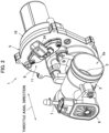
- FIG. 2 is a perspective view of the throttle device seen from another angle.
- a throttle device 1 is adapted to be attached to a single-cylinder engine mounted as a power source for traveling on a motorized two-wheeled vehicle.
- a throttle bore 2a that communicates with the inside of the cylinder of the engine, which is not illustrated, is formed to penetrate through a throttle body 2 of the throttle device 1.
- one end of the throttle bore 2a is connected to an air cleaner, the other end is connected to an intake manifold of the engine, and intake air filtrated by the air cleaner is supplied to the inside of the cylinder of the engine through the throttle bore 2a and the intake manifold.
- a throttle valve 3 is supported inside the throttle bore 2a by a throttle shaft 4 such that the throttle valve 3 can open and close, the throttle shaft 4 is driven by a gear unit 5 attached to the throttle body 2, and the throttle valve 3 is thereby opened or closed to adjust the amount of intake air.
- 6 in FIGS. 1 and 2 denotes a throttle position sensor that detects the opening degree of the throttle valve 3
- 7 denotes a intake air pressure extracting port that is connected to a intake air pressure sensor, which is not illustrated.
- the direction which an axial line C3 of the throttle shaft 4 follows may be referred to as a throttle axial direction.
- FIG. 3 is an exploded perspective view illustrating the gear unit 5
- FIG. 4 is a side view illustrating a mating state of each gear inside a gear accommodating chamber with a gear cover detached therefrom
- FIG. 5 is a sectional view along the line V-V in FIG. 4 illustrating a mating state of each gear inside the gear accommodating chamber.
- a gear case 9 is attached to one side of the throttle body 2 in the throttle axial direction, a gear cover 10 is fastened to the gear case 9 with a screw 8, and a gear accommodating chamber 11 is defined therein.
- One end of the throttle shaft 4 projects to the inside of the gear accommodating chamber 11, and a driven gear 14 is fastened thereto via a washer 13 by a bolt 12.
- a motor 15 is disposed inside a motor chamber 10a formed in the gear cover 10, and an output shaft 15a thereof projects to the inside of the gear accommodating chamber 11 along an axial line C1 that is parallel with an axial line C3 of the throttle shaft 4 with a driving gear 16 secured to the output shaft 15a.
- the gear case 9 may be formed integrally with the throttle body 2.
- a support shaft 17 is disposed between the driven gear 14 and the driving gear 16 inside the gear accommodating chamber 11, the support shaft 17 is maintained in a posture along an axial line C2 that is parallel with the axial line C3 of the throttle shaft 4, and one end 17a thereof is press-fitted into a press-fitting hole 18 penetrating through the gear case 9.
- An intermediate gear 19 is rotatably supported by the support shaft 17, and the other end 17b of the support shaft 17 projects on the side of the gear cover 10 from an end surface of the intermediate gear 19 and is fitted into a positioning hole 20 formed in the gear cover 10.
- the intermediate gear 19 includes a large diameter portion 19a that mates with the driving gear 16 and a small diameter portion 19b that is integrally provided in parallel with the large diameter portion 19a on the side of the gear case 9 and mates with the driven gear 14. Therefore, rotation of the driving gear 16 caused by the motor 15 is transmitted to the large diameter portion 19a of the intermediate gear 19 and is further transmitted from the small diameter portion 19b to the driven gear 14.
- a return spring 22 is wound around the throttle shaft 4 inside the gear accommodating chamber 11 and biases the throttle valve 3 in a closing direction along with the throttle shaft 4.
- a pair of contact points 15b of the motor 15 are electrically connected to a connector 24 provided in the gear case 9.
- a harness extending from a controller on the side of a vehicle body is connected to the connector 24, the motor 15 is controlled by the controller in accordance with the amount of throttle operation of the vehicle and the like, and the throttle valve 3 is driven and opened or closed.
- the throttle device 1 employs a procedure of performing assembly operations of the throttle body 2 side and the gear cover 10 side in parallel and coupling them to each other after completion of the assembling.
- the throttle valve 3, the throttle shaft 4, the driven gear 14, the gear case 9, the support shaft 17, and the intermediate gear 19 are assembled with the throttle body 2, and the state after the assembling will be referred to as a throttle body-side assembly 26 below.
- the motor 15 and the driving gear 16 are assembled with the gear cover 10, and the state after the assembling will be referred to as a gear cover-side assembly 27 below.
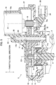
- FIG. 6 is a sectional view illustrating a state where the throttle body-side assembly 26 and the gear cover-side assembly 27 are caused to face each other
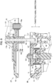
- FIG. 7 is a sectional view illustrating a state where the throttle body-side assembly 26 and the gear cover-side assembly 27 are caused to approach each other to establish coupling therebetween.
- a projecting length L1 is set to be longer than a projecting length L2 when the projecting length of the other end 17b of the support shaft 17 from the end surface of the large diameter portion 19a of the intermediate gear 19 is assumed to be L1 and the projecting length of the driving gear 16 from the opening surface of the gear cover 10 in which the positioning hole 20 is open is assumed to be L2 in the throttle axial direction (L1 > L2).
- the throttle body-side assembly 26 and the gear cover-side assembly 27 are caused to face each other.
- the other end 17b of the support shaft 17 and the opening portion of the positioning hole 20 face each other, and the outer periphery of the large diameter portion 19a of the intermediate gear 19 and the outer periphery of the driving gear 16 face each other.
- the fitting length of the support shaft 17 exceeds L3 and further increases, and the mating length between the large diameter portion 19a and the driving gear 16 in the throttle axial direction gradually increases. Then, the large diameter portion 19a of the intermediate gear 19 and the driving gear 16 completely mate with each other at the point when the gear case 9 and the gear cover 10 are coupled to each other as illustrated in FIG. 5 , and the coupling operation is completed by fastening the gear case 9 and the gear cover 10 with a screw 8.
- the support shaft 17 functions as a so-called positioning pin at and after the point, the positional relationship between the large diameter portion 19a of the intermediate gear 19 and the driving gear 16, in other words, a gear pitch is fixed, and the operation of causing the large diameter portion 19a and the driving gear 16 to mate with each other is performed in this state.
- the timing at which the support shaft 17 starts to be fitted into the positioning hole 20 is delayed by the amount corresponding to the lengths l1 and l2 of the chamfered portions 28 and 29 in the process of causing the assemblies 26 and 27 to approach each other.
- the support shaft 17 it is possible to cause the support shaft 17 to start to be fitted into the positioning hole 20 prior to the start of the mating between the gears if the projecting length L1 of the shaft 17 is set to be longer than the projecting length L2 of the driving gear 16 in a case where the chamfered portions 28 and 29 are not provided.
- the substantial projecting length L1 of the support shaft 17 decreases by the amount corresponding to the lengths l1 and l2 thereof.
- the value L3 that is greater than the total l1 + l2 of the lengths l1 and l2 is added to the projecting length L2 to set the projecting length L1. Therefore, the support shaft 17 is reliably fitted into the positioning hole 20 before the timing when the gears start to mate with each other as described above on the basis of FIG. 7 , and it is thus possible to achieve the aforementioned advantages regarding the operation of causing the gears to mate with each other.
- the projecting length L1 may be set to be any value that is sufficiently greater than the projecting length L2 without considering the specific lengths l1 and l2 of the chamfered portions 28 and 29.
- the motor 15 of the gear cover-side assembly 27 is attached to the gear cover 10 in a posture with the output shaft 15a directed in a direction in which the positioning hole 20 in the gear cover 10 is open.
- the positioning hole 20 and the output shaft 15a are directed in the same direction, it is possible to adjust the position of the motor 15 by using a jig 30 as illustrated in FIG. 8 .
- a positioning pin 30a and a positioning hole 30b are formed in the jig 30 at a gap corresponding to the gear pitch, the positioning pin 30a is fitted into the positioning hole 20 of the gear cover 10, and the positioning hole 20 is fitted onto the output shaft 15a of the motor 15. In this manner, the motor 15 is adjusted to a normal position, and if the motor 15 is secured in this state, it is possible to maintain the positioning hole 20 and the output shaft 15a at a normal gear pitch.
- the intermediate gear 19 and the support shaft 17 are provided in the throttle body-side assembly 26, the support shaft 17 is fitted into the positioning hole 20 of the gear cover 10, and the large diameter portion 19a of the intermediate gear 19 is caused to mate with the output shaft 15a of the motor 15, with the coupling to the gear cover-side assembly 27.
- the present invention is not limited thereto, and the intermediate gear 19 and the support shaft 17 may be provided in the gear cover-side assembly 27, for example, which will be described below as another example 1.
- the same member numbers will be applied to portions with the same configurations as those in the embodiment, description thereof will be omitted, and differences will be mainly described.
- FIG. 9 is a sectional view illustrating a throttle device 1 in another example 1 in which an intermediate gear 19 and a support shaft 17 are provided on the side of a gear case 9 and corresponding to FIG. 6
- FIG. 10 is a sectional view illustrating the throttle device 1 in another example 1 and corresponding to FIG. 7 .
- a press-fitting hole 41 is formed in a gear cover 10 instead of the positioning hole 20 in the embodiment, and one end 17a of the support shaft 17 is press-fitted into the press-fitting hole 41.
- An intermediate gear 19 is rotatably supported by the support shaft 17, and a large diameter portion 19a thereof mates with a driving gear 16. Therefore, the gear cover 10, a motor 15, the driving gear 16, the intermediate gear 19, and the support shaft 17 configure a gear cover-side assembly 27 in another example 1.
- a positioning hole 42 is formed in the gear case 9 instead of the press-fitting hole 18 in the embodiment, and the other end 17b of the support shaft 17 is press-fitted into the positioning hole 42 when the assemblies 26 and 27 are coupled to each other. Therefore, a throttle valve 3, a throttle shaft 4, a driven gear 14, and the gear case 9 configure a throttle body-side assembly 26 in another example 1.
- a projecting length L1 is set to be longer than a projecting length L2 when the projecting length of the other end 17b of the support shaft 17 from an end surface of the small diameter portion 19b of the intermediate gear 19 is assumed to be L1 and the projecting length of the driven gear 14 from an opening surface of the gear case 9 in which the positioning hole 42 is open is assumed to be L2 in the throttle axial direction (L1 > L2).
- the projecting length L1 may be set on the basis of a value L3 in consideration of a chamfered portion 28 at the other end 17b of the support shaft 17 and the chamfered portion 29 at the opening portion of the positioning hole 42 similarly to the embodiment.
- the other end 17b of the support shaft 17 starts to be fitted into the positioning hole 42 first, and the small diameter portion 19b of the intermediate gear 19 and the driven gear 14 start to mate with each other at a point at which the support shaft 17 is fitted into the positioning hole 42 to some extent as illustrated in FIG. 10 . Therefore, although repeated description is omitted, it is possible to perform the operation of fitting the support shaft 17 into the positioning hole 42 and the mating between the gears in order, and it is possible to concentrate on each operation. Additionally, since the operation of causing the gears to mate with each other is performed in a state where the gear pitch has been fixed by the support shaft 17 being fitted into the positioning hole 42, it is possible to easily cause the gears to mate with each other.
- the motor 15 provided at the gear cover-side assembly 27 is attached to the gear cover 10 in a posture with the output shaft 15a directed in a direction in which the support shaft 17 of the gear cover 10 projects. Therefore, although not illustrated, it is possible to adjust the position of the motor 15 by using a jig including a positioning hole into which the support shaft 17 is fitted and a positioning hole which is fitted onto the output shaft 15a similarly to the jig 30 in the embodiment.
- rotation of the driving gear 16 is transmitted to the driven gear 14 via a single intermediate gear 19 in the embodiment, the present invention is not limited thereto.
- the rotation may be transmitted via a plurality of intermediate gears, which will be described below as another example 2.
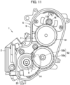
- FIG. 11 is a side view illustrating a throttle device 1 in another example 2 in which a pair of intermediate gears are included and corresponding to FIG. 4 .
- Rotation of a driving gear 16 is transmitted to a first intermediate gear 51 that functions as an idler gear and is further transmitted to a large diameter portion 52a of a second intermediate gear 52. Rotation of a small diameter portion 52b of the second intermediate gear 52 is transmitted to a driven gear 14, and a throttle valve 3 is thereby opened or closed along with a throttle shaft 4.
- the driving gear 16 is caused to mate with the first intermediate gear 51 with coupling between assemblies 26 and 27 in a case where only the driving gear 16 is provided in the gear cover-side assembly 27, for example.
- the first intermediate gear 51 is caused to mate with the large diameter portion 52a of the second intermediate gear 52 with the coupling between the assemblies 26 and 27 in a case where the driving gear 16 and the first intermediate gear 51 are provided in the gear cover-side assembly 27.
- the small diameter portion 52b of the second intermediate gear 52 is caused to mate with the driven gear 14 with the coupling between the assemblies 26 and 27.
- the present invention is not limited thereto and can be applied to a throttle device for an engine mounted on various vehicles.
- the throttle device according to the present invention may be applied to engines used for applications other than the power source for traveling, for example, an engine for a power generator.
- the present invention may be implemented as a multiple-throttle device including a plurality of throttle bores.
Landscapes
- Engineering & Computer Science (AREA)
- Chemical & Material Sciences (AREA)
- Combustion & Propulsion (AREA)
- Mechanical Engineering (AREA)
- General Engineering & Computer Science (AREA)
- Manufacturing & Machinery (AREA)
- Control Of Throttle Valves Provided In The Intake System Or In The Exhaust System (AREA)
Applications Claiming Priority (1)
| Application Number | Priority Date | Filing Date | Title |
|---|---|---|---|
| JP2022119786A JP7844277B2 (ja) | 2022-07-27 | 2022-07-27 | エンジンのスロットル装置 |
Publications (1)
| Publication Number | Publication Date |
|---|---|
| EP4311925A1 true EP4311925A1 (de) | 2024-01-31 |
Family
ID=87429300
Family Applications (1)
| Application Number | Title | Priority Date | Filing Date |
|---|---|---|---|
| EP23186923.1A Withdrawn EP4311925A1 (de) | 2022-07-27 | 2023-07-21 | Drosselvorrichtung für einen motor |
Country Status (3)
| Country | Link |
|---|---|
| US (1) | US12196152B2 (de) |
| EP (1) | EP4311925A1 (de) |
| JP (1) | JP7844277B2 (de) |
Citations (4)
| Publication number | Priority date | Publication date | Assignee | Title |
|---|---|---|---|---|
| WO2000058614A1 (en) * | 1999-03-29 | 2000-10-05 | Hitachi, Ltd. | Electronically controlled throttle device |
| JP2006097627A (ja) | 2004-09-30 | 2006-04-13 | Keihin Corp | スロットル弁制御装置 |
| EP2202398A2 (de) * | 2008-12-23 | 2010-06-30 | Robert Bosch GmbH | Stelleinrichtung |
| US9562483B2 (en) * | 2013-03-13 | 2017-02-07 | Keihin Corporation | Engine intake control apparatus |
Family Cites Families (2)
| Publication number | Priority date | Publication date | Assignee | Title |
|---|---|---|---|---|
| JPH0350348A (ja) * | 1989-07-18 | 1991-03-04 | Honda Motor Co Ltd | 車載エンジンの制御弁装置 |
| JP3810946B2 (ja) * | 1999-06-03 | 2006-08-16 | 株式会社日立製作所 | 電動式スロットルバルブ装置 |
-
2022
- 2022-07-27 JP JP2022119786A patent/JP7844277B2/ja active Active
-
2023
- 2023-07-06 US US18/218,629 patent/US12196152B2/en active Active
- 2023-07-21 EP EP23186923.1A patent/EP4311925A1/de not_active Withdrawn
Patent Citations (4)
| Publication number | Priority date | Publication date | Assignee | Title |
|---|---|---|---|---|
| WO2000058614A1 (en) * | 1999-03-29 | 2000-10-05 | Hitachi, Ltd. | Electronically controlled throttle device |
| JP2006097627A (ja) | 2004-09-30 | 2006-04-13 | Keihin Corp | スロットル弁制御装置 |
| EP2202398A2 (de) * | 2008-12-23 | 2010-06-30 | Robert Bosch GmbH | Stelleinrichtung |
| US9562483B2 (en) * | 2013-03-13 | 2017-02-07 | Keihin Corporation | Engine intake control apparatus |
Also Published As
| Publication number | Publication date |
|---|---|
| US12196152B2 (en) | 2025-01-14 |
| JP7844277B2 (ja) | 2026-04-13 |
| JP2024017264A (ja) | 2024-02-08 |
| US20240035420A1 (en) | 2024-02-01 |
Similar Documents
| Publication | Publication Date | Title |
|---|---|---|
| US20100251519A1 (en) | Motor-Driven Modular Trunk Hinge | |
| CN101689792B (zh) | 转子安装装置和转子安装方法 | |
| DE102008052846C5 (de) | Abgasklappenantrieb für ein Kraftfahrzeug sowie die Verwendung eines solchen Abgasklappenantriebes | |
| JPH10122089A (ja) | 燃料供給装置およびその製造方法 | |
| WO2007107458A3 (de) | Antriebsvorrichtung mit einem mechanisch angetriebenen zusatzaggregat, verfahren zum betreiben der antriebsvorrichtung und mittel zur durchführung des verfahrens | |
| US6324744B1 (en) | Method of mounting and axially aligning an engine accessory | |
| EP3856612B1 (de) | Lenkvorrichtung mit einer steckverbindereinheit zur elektrischen kontaktierung einer lenksensoreinheit | |
| US12196152B2 (en) | Throttle device for engine | |
| KR930002427B1 (ko) | 자동변속기의 드로틀케이블 배색(配色)방법 및 그 장착구조 | |
| EP1156200A2 (de) | Klappenstelleinheit | |
| CN102667108A (zh) | 具有连接器的电路模块 | |
| US20080245143A1 (en) | Throttle position sensor assembly | |
| KR100679286B1 (ko) | 포트 시스템, 특히 내연 기관용 흡입 매니폴드 | |
| DE19825727A1 (de) | Drosselklappenstutzen | |
| US7281528B2 (en) | Method and apparatus for a mechanically driven supercharger | |
| JPH03117680A (ja) | 2サイクルエンジンの燃料供給装置 | |
| CN217401020U (zh) | 一种电子节气门 | |
| KR200452129Y1 (ko) | 연료펌프의 구동기어부 탈착 보조장치 및 이를 이용한 구동기어부 장착방법 | |
| US20110050012A1 (en) | Electrical internal combustion engine actuating arrangement | |
| KR102940433B1 (ko) | 전자식 스로틀 액추에이터의 축간거리 개선구조의 조립방법 | |
| EP4019757A1 (de) | Motordrosselvorrichtung | |
| US9541009B2 (en) | Intake device | |
| US11346292B2 (en) | General engine throttle apparatus | |
| KR101498818B1 (ko) | 전자식 스로틀 어셈블리 | |
| KR100534309B1 (ko) | 자동차용 연료필라도어의 결합구조 |
Legal Events
| Date | Code | Title | Description |
|---|---|---|---|
| PUAI | Public reference made under article 153(3) epc to a published international application that has entered the european phase |
Free format text: ORIGINAL CODE: 0009012 |
|
| STAA | Information on the status of an ep patent application or granted ep patent |
Free format text: STATUS: THE APPLICATION HAS BEEN PUBLISHED |
|
| AK | Designated contracting states |
Kind code of ref document: A1 Designated state(s): AL AT BE BG CH CY CZ DE DK EE ES FI FR GB GR HR HU IE IS IT LI LT LU LV MC ME MK MT NL NO PL PT RO RS SE SI SK SM TR |
|
| STAA | Information on the status of an ep patent application or granted ep patent |
Free format text: STATUS: REQUEST FOR EXAMINATION WAS MADE |
|
| 17P | Request for examination filed |
Effective date: 20240712 |
|
| RBV | Designated contracting states (corrected) |
Designated state(s): AL AT BE BG CH CY CZ DE DK EE ES FI FR GB GR HR HU IE IS IT LI LT LU LV MC ME MK MT NL NO PL PT RO RS SE SI SK SM TR |
|
| STAA | Information on the status of an ep patent application or granted ep patent |
Free format text: STATUS: EXAMINATION IS IN PROGRESS |
|
| 17Q | First examination report despatched |
Effective date: 20251209 |
|
| STAA | Information on the status of an ep patent application or granted ep patent |
Free format text: STATUS: THE APPLICATION HAS BEEN WITHDRAWN |
|
| 18W | Application withdrawn |
Effective date: 20260202 |