EP4311376A1 - Surface modification method - Google Patents
Surface modification method Download PDFInfo
- Publication number
- EP4311376A1 EP4311376A1 EP22771328.6A EP22771328A EP4311376A1 EP 4311376 A1 EP4311376 A1 EP 4311376A1 EP 22771328 A EP22771328 A EP 22771328A EP 4311376 A1 EP4311376 A1 EP 4311376A1
- Authority
- EP
- European Patent Office
- Prior art keywords
- treatment target
- plasma
- treatment
- atom
- process gas
- Prior art date
- Legal status (The legal status is an assumption and is not a legal conclusion. Google has not performed a legal analysis and makes no representation as to the accuracy of the status listed.)
- Pending
Links
Images


Classifications
-
- H—ELECTRICITY
- H01—ELECTRIC ELEMENTS
- H01J—ELECTRIC DISCHARGE TUBES OR DISCHARGE LAMPS
- H01J37/00—Discharge tubes with provision for introducing objects or material to be exposed to the discharge, e.g. for the purpose of examination or processing thereof
- H01J37/32—Gas-filled discharge tubes
- H01J37/32431—Constructional details of the reactor
- H01J37/32798—Further details of plasma apparatus not provided for in groups H01J37/3244 - H01J37/32788; special provisions for cleaning or maintenance of the apparatus
- H01J37/32816—Pressure
- H01J37/32825—Working under atmospheric pressure or higher
-
- C—CHEMISTRY; METALLURGY
- C08—ORGANIC MACROMOLECULAR COMPOUNDS; THEIR PREPARATION OR CHEMICAL WORKING-UP; COMPOSITIONS BASED THEREON
- C08J—WORKING-UP; GENERAL PROCESSES OF COMPOUNDING; AFTER-TREATMENT NOT COVERED BY SUBCLASSES C08B, C08C, C08F, C08G or C08H
- C08J7/00—Chemical treatment or coating of shaped articles made of macromolecular substances
- C08J7/12—Chemical modification
- C08J7/123—Treatment by wave energy or particle radiation
-
- C—CHEMISTRY; METALLURGY
- C08—ORGANIC MACROMOLECULAR COMPOUNDS; THEIR PREPARATION OR CHEMICAL WORKING-UP; COMPOSITIONS BASED THEREON
- C08J—WORKING-UP; GENERAL PROCESSES OF COMPOUNDING; AFTER-TREATMENT NOT COVERED BY SUBCLASSES C08B, C08C, C08F, C08G or C08H
- C08J5/00—Manufacture of articles or shaped materials containing macromolecular substances
- C08J5/18—Manufacture of films or sheets
-
- C—CHEMISTRY; METALLURGY
- C23—COATING METALLIC MATERIAL; COATING MATERIAL WITH METALLIC MATERIAL; CHEMICAL SURFACE TREATMENT; DIFFUSION TREATMENT OF METALLIC MATERIAL; COATING BY VACUUM EVAPORATION, BY SPUTTERING, BY ION IMPLANTATION OR BY CHEMICAL VAPOUR DEPOSITION, IN GENERAL; INHIBITING CORROSION OF METALLIC MATERIAL OR INCRUSTATION IN GENERAL
- C23C—COATING METALLIC MATERIAL; COATING MATERIAL WITH METALLIC MATERIAL; SURFACE TREATMENT OF METALLIC MATERIAL BY DIFFUSION INTO THE SURFACE, BY CHEMICAL CONVERSION OR SUBSTITUTION; COATING BY VACUUM EVAPORATION, BY SPUTTERING, BY ION IMPLANTATION OR BY CHEMICAL VAPOUR DEPOSITION, IN GENERAL
- C23C16/00—Chemical coating by decomposition of gaseous compounds, without leaving reaction products of surface material in the coating, i.e. chemical vapour deposition [CVD] processes
- C23C16/44—Chemical coating by decomposition of gaseous compounds, without leaving reaction products of surface material in the coating, i.e. chemical vapour deposition [CVD] processes characterised by the method of coating
- C23C16/50—Chemical coating by decomposition of gaseous compounds, without leaving reaction products of surface material in the coating, i.e. chemical vapour deposition [CVD] processes characterised by the method of coating using electric discharges
- C23C16/503—Chemical coating by decomposition of gaseous compounds, without leaving reaction products of surface material in the coating, i.e. chemical vapour deposition [CVD] processes characterised by the method of coating using electric discharges using DC or AC discharges
-
- H—ELECTRICITY
- H01—ELECTRIC ELEMENTS
- H01J—ELECTRIC DISCHARGE TUBES OR DISCHARGE LAMPS
- H01J37/00—Discharge tubes with provision for introducing objects or material to be exposed to the discharge, e.g. for the purpose of examination or processing thereof
- H01J37/32—Gas-filled discharge tubes
- H01J37/32009—Arrangements for generation of plasma specially adapted for examination or treatment of objects, e.g. plasma sources
- H01J37/32073—Corona discharge
-
- H—ELECTRICITY
- H01—ELECTRIC ELEMENTS
- H01J—ELECTRIC DISCHARGE TUBES OR DISCHARGE LAMPS
- H01J37/00—Discharge tubes with provision for introducing objects or material to be exposed to the discharge, e.g. for the purpose of examination or processing thereof
- H01J37/32—Gas-filled discharge tubes
- H01J37/32009—Arrangements for generation of plasma specially adapted for examination or treatment of objects, e.g. plasma sources
- H01J37/32348—Dielectric barrier discharge
-
- H—ELECTRICITY
- H01—ELECTRIC ELEMENTS
- H01J—ELECTRIC DISCHARGE TUBES OR DISCHARGE LAMPS
- H01J37/00—Discharge tubes with provision for introducing objects or material to be exposed to the discharge, e.g. for the purpose of examination or processing thereof
- H01J37/32—Gas-filled discharge tubes
- H01J37/32009—Arrangements for generation of plasma specially adapted for examination or treatment of objects, e.g. plasma sources
- H01J37/32357—Generation remote from the workpiece, e.g. down-stream
-
- H—ELECTRICITY
- H01—ELECTRIC ELEMENTS
- H01J—ELECTRIC DISCHARGE TUBES OR DISCHARGE LAMPS
- H01J37/00—Discharge tubes with provision for introducing objects or material to be exposed to the discharge, e.g. for the purpose of examination or processing thereof
- H01J37/32—Gas-filled discharge tubes
- H01J37/32009—Arrangements for generation of plasma specially adapted for examination or treatment of objects, e.g. plasma sources
- H01J37/32366—Localised processing
- H01J37/32376—Scanning across large workpieces
-
- H—ELECTRICITY
- H01—ELECTRIC ELEMENTS
- H01J—ELECTRIC DISCHARGE TUBES OR DISCHARGE LAMPS
- H01J37/00—Discharge tubes with provision for introducing objects or material to be exposed to the discharge, e.g. for the purpose of examination or processing thereof
- H01J37/32—Gas-filled discharge tubes
- H01J37/32431—Constructional details of the reactor
- H01J37/3244—Gas supply means
-
- H—ELECTRICITY
- H01—ELECTRIC ELEMENTS
- H01J—ELECTRIC DISCHARGE TUBES OR DISCHARGE LAMPS
- H01J37/00—Discharge tubes with provision for introducing objects or material to be exposed to the discharge, e.g. for the purpose of examination or processing thereof
- H01J37/32—Gas-filled discharge tubes
- H01J37/32431—Constructional details of the reactor
- H01J37/32532—Electrodes
- H01J37/32541—Shape
-
- H—ELECTRICITY
- H01—ELECTRIC ELEMENTS
- H01J—ELECTRIC DISCHARGE TUBES OR DISCHARGE LAMPS
- H01J37/00—Discharge tubes with provision for introducing objects or material to be exposed to the discharge, e.g. for the purpose of examination or processing thereof
- H01J37/32—Gas-filled discharge tubes
- H01J37/32431—Constructional details of the reactor
- H01J37/32733—Means for moving the material to be treated
- H01J37/32752—Means for moving the material to be treated for moving the material across the discharge
- H01J37/32761—Continuous moving
- H01J37/3277—Continuous moving of continuous material
-
- H—ELECTRICITY
- H05—ELECTRIC TECHNIQUES NOT OTHERWISE PROVIDED FOR
- H05H—PLASMA TECHNIQUE; PRODUCTION OF ACCELERATED ELECTRICALLY-CHARGED PARTICLES OR OF NEUTRONS; PRODUCTION OR ACCELERATION OF NEUTRAL MOLECULAR OR ATOMIC BEAMS
- H05H1/00—Generating plasma; Handling plasma
- H05H1/24—Generating plasma
- H05H1/2406—Generating plasma using dielectric barrier discharges, i.e. with a dielectric interposed between the electrodes
-
- H—ELECTRICITY
- H05—ELECTRIC TECHNIQUES NOT OTHERWISE PROVIDED FOR
- H05H—PLASMA TECHNIQUE; PRODUCTION OF ACCELERATED ELECTRICALLY-CHARGED PARTICLES OR OF NEUTRONS; PRODUCTION OR ACCELERATION OF NEUTRAL MOLECULAR OR ATOMIC BEAMS
- H05H1/00—Generating plasma; Handling plasma
- H05H1/24—Generating plasma
- H05H1/2406—Generating plasma using dielectric barrier discharges, i.e. with a dielectric interposed between the electrodes
- H05H1/2431—Generating plasma using dielectric barrier discharges, i.e. with a dielectric interposed between the electrodes using cylindrical electrodes, e.g. rotary drums
-
- H—ELECTRICITY
- H05—ELECTRIC TECHNIQUES NOT OTHERWISE PROVIDED FOR
- H05H—PLASMA TECHNIQUE; PRODUCTION OF ACCELERATED ELECTRICALLY-CHARGED PARTICLES OR OF NEUTRONS; PRODUCTION OR ACCELERATION OF NEUTRAL MOLECULAR OR ATOMIC BEAMS
- H05H1/00—Generating plasma; Handling plasma
- H05H1/24—Generating plasma
- H05H1/2406—Generating plasma using dielectric barrier discharges, i.e. with a dielectric interposed between the electrodes
- H05H1/2443—Generating plasma using dielectric barrier discharges, i.e. with a dielectric interposed between the electrodes the plasma fluid flowing through a dielectric tube
- H05H1/246—Generating plasma using dielectric barrier discharges, i.e. with a dielectric interposed between the electrodes the plasma fluid flowing through a dielectric tube the plasma being activated using external electrodes
-
- H—ELECTRICITY
- H05—ELECTRIC TECHNIQUES NOT OTHERWISE PROVIDED FOR
- H05H—PLASMA TECHNIQUE; PRODUCTION OF ACCELERATED ELECTRICALLY-CHARGED PARTICLES OR OF NEUTRONS; PRODUCTION OR ACCELERATION OF NEUTRAL MOLECULAR OR ATOMIC BEAMS
- H05H1/00—Generating plasma; Handling plasma
- H05H1/24—Generating plasma
- H05H1/47—Generating plasma using corona discharges
-
- C—CHEMISTRY; METALLURGY
- C08—ORGANIC MACROMOLECULAR COMPOUNDS; THEIR PREPARATION OR CHEMICAL WORKING-UP; COMPOSITIONS BASED THEREON
- C08J—WORKING-UP; GENERAL PROCESSES OF COMPOUNDING; AFTER-TREATMENT NOT COVERED BY SUBCLASSES C08B, C08C, C08F, C08G or C08H
- C08J2327/00—Characterised by the use of homopolymers or copolymers of compounds having one or more unsaturated aliphatic radicals, each having only one carbon-to-carbon double bond, and at least one being terminated by a halogen; Derivatives of such polymers
- C08J2327/02—Characterised by the use of homopolymers or copolymers of compounds having one or more unsaturated aliphatic radicals, each having only one carbon-to-carbon double bond, and at least one being terminated by a halogen; Derivatives of such polymers not modified by chemical after-treatment
- C08J2327/12—Characterised by the use of homopolymers or copolymers of compounds having one or more unsaturated aliphatic radicals, each having only one carbon-to-carbon double bond, and at least one being terminated by a halogen; Derivatives of such polymers not modified by chemical after-treatment containing fluorine atoms
-
- C—CHEMISTRY; METALLURGY
- C08—ORGANIC MACROMOLECULAR COMPOUNDS; THEIR PREPARATION OR CHEMICAL WORKING-UP; COMPOSITIONS BASED THEREON
- C08J—WORKING-UP; GENERAL PROCESSES OF COMPOUNDING; AFTER-TREATMENT NOT COVERED BY SUBCLASSES C08B, C08C, C08F, C08G or C08H
- C08J2327/00—Characterised by the use of homopolymers or copolymers of compounds having one or more unsaturated aliphatic radicals, each having only one carbon-to-carbon double bond, and at least one being terminated by a halogen; Derivatives of such polymers
- C08J2327/02—Characterised by the use of homopolymers or copolymers of compounds having one or more unsaturated aliphatic radicals, each having only one carbon-to-carbon double bond, and at least one being terminated by a halogen; Derivatives of such polymers not modified by chemical after-treatment
- C08J2327/12—Characterised by the use of homopolymers or copolymers of compounds having one or more unsaturated aliphatic radicals, each having only one carbon-to-carbon double bond, and at least one being terminated by a halogen; Derivatives of such polymers not modified by chemical after-treatment containing fluorine atoms
- C08J2327/18—Homopolymers or copolymers of tetrafluoroethylene
-
- H—ELECTRICITY
- H05—ELECTRIC TECHNIQUES NOT OTHERWISE PROVIDED FOR
- H05H—PLASMA TECHNIQUE; PRODUCTION OF ACCELERATED ELECTRICALLY-CHARGED PARTICLES OR OF NEUTRONS; PRODUCTION OR ACCELERATION OF NEUTRAL MOLECULAR OR ATOMIC BEAMS
- H05H2245/00—Applications of plasma devices
- H05H2245/40—Surface treatments
Definitions
- the present invention relates to a method for surface-modifying a treatment target made of a hard-to-adhere material, and particularly to a surface modification method for a fluorine-based hard-to-adhere material containing a fluorine atom.
- fluorine-based resins such as polytetrafluoroethylene (PTFE) and ethylene tetrafluoroethylene (ETFE) have low wettability, and aqueous adhesives such as polyvinyl alcohol (hereinafter, appropriately referred to as "PVA")-based adhesives or polyether-based adhesives do not adhere well to those resins.
- PVA polyvinyl alcohol
- wet treatment using a chemical solution has been conventionally performed (see, for example, Patent Literature 1), but this method requires disposal of waste liquid and has problems such as high running cost and environmental load.
- dry treatment has been proposed in which a process gas is activated by plasma or the like and is brought into contact with a hard-to-adhere material (see, for example, Patent Literature 2).
- Patent Literature 2 a mixed gas obtained by adding water vapor to an inert gas such as helium, argon, neon, or nitrogen is used as a process gas.
- the process gas is activated by supplying the process gas to between a pair of electrodes and generating atmospheric pressure plasma through the application of a high-frequency voltage of several hundred kHz to several tens MHz to between the electrodes.
- a treatment target made of fluororesin film is stretched between support rolls located on both sides of the pair of electrodes forming a parallel plate electrode to pass between the pair of electrodes.
- the treatment target is surface-modified by plasma application.
- a primary (first) purpose of the present invention to present a surface state for acquiring a desired degree of surface modification in dry-treating, with plasma, a treatment target made of a fluorine-based hard-to-adhere material containing a fluorine atom and sufficiently improve the wettability and eventually the adhesiveness of the fluorine-based hard-to-adhere material.
- a second purpose is to make it possible to reliably treat only a surface that is intended to be treated with being less affected by wrinkles or slack and without damaging the treatment target.
- the present inventors have found that the wettability of a hard-to-adhere material is improved by setting conditions such that the rate of decrease in the content of fluorine atoms on the surface of a fluorine-based hard-to-adhere material by plasma using a process gas to which a specific gas component is added falls within a prescribed range.
- the present invention has been made based on this finding, and is a method for surface-modifying a treatment target made of a hard-to-adhere material containing a fluorine atom, the method comprising:
- the plasma step includes:
- the term "near atmospheric pressure” refers to a range of 1.013 ⁇ 10 4 to 50.663 ⁇ 10 4 Pa, and in consideration of facilitation of pressure adjustment and simplification of a device configuration, it is preferably 1.333 ⁇ 10 4 to 10.664 ⁇ 10 4 Pa, and more preferably 9.331 ⁇ 10 4 to 10.397 ⁇ 10 4 Pa.
- an amount of energy input in the plasma step is 0.9 J/cm 2 to 135.0 J/cm 2 per unit area of the surface of the treatment target.
- the plasma step includes a step in which the treatment target passes through in the interelectrode space.
- the plasma step includes a step of applying a pulse wave-like voltage to between the pair of electrodes to generate pulse plasma near atmospheric pressure in the interelectrode space.
- a peak-to-peak voltage of a voltage applied to between the pair of electrodes is preferably 3 kVpp to 25 kVpp, and more preferably 12 kVpp to 20 kVpp, and the frequency is preferably 10 kHz to 70 kHz, and more preferably 20 kHz to 55 kHz.
- the treatment target has a film shape
- the plasma step includes a step of applying a pulse wave-like voltage to between the pair of electrodes to generate pulse plasma near the atmospheric pressure in the interelectrode space.
- the treating region can be expanded by increasing the number of electrode pairs composed of a hot electrode and a rolled ground electrode. As a result, both quality and performance can be kept good, and the second purpose can be achieved.
- the wettability and the adhesiveness of a treatment target made of a fluorine-based hard-to-adhere material can be improved, and a desired degree of surface modification can be acquired.
- FIG. 1 illustrates a surface modification device 1 according to the first embodiment of the present invention.
- a treatment target 9 is a hard-to-adhere material containing fluorine atoms.
- a hard-to-adhere material include fluorine-based resins such as polytetrafluoroethylene (PTFE) and ethylene tetrafluoroethylene (ETFE).
- PTFE polytetrafluoroethylene
- ETFE ethylene tetrafluoroethylene
- the shape of the treatment target 9 is not particularly limited, and may be, for example, a film shape, a plate shape, or a block shape.
- the surface modification device 1 modifies the surface of the treatment target 9 made of the hard-to-adhere material to improve adhesiveness, and includes a process gas supply unit 10 and a plasma generation unit 20.
- the process gas supply unit 10 supplies a process gas to the plasma generation unit 20.
- the process gas contains any one or two or more among carbon monoxide, carbon dioxide, hydrogen, water vapor, ethanol, propanol, hexanol, ethylene glycol, and ammonia as an additive component.
- the additive component is added to a carrier gas to yield the process gas.
- a mass flow controller MFC
- bubbling may be used.
- the carrier gas examples include an inert gas such as nitrogen (N 2 ).
- N 2 nitrogen
- a noble gas may be used instead of nitrogen.
- the carrier gas serves as a carrier gas that conveys the process gas containing the additive component to the plasma generation unit 20 and the treatment target 9, and also serves as a dilution gas that dilutes the additive component and as a discharge generation gas in the plasma generation unit 20.
- the plasma generation unit 20 includes a pair of electrodes 21 and 22 and a plasma head 25.
- the hot electrode 21 is accommodated in the plasma head 25.
- the hot electrode 21 is formed in an elongated plate shape extending in a treating width direction orthogonal to the plane of FIG. 1 .
- the dimension of the hot electrode 21 in the treating width direction is substantially equal to or slightly larger than the treating width (the dimension in a direction orthogonal to the plane of FIG. 1 ) of the treatment target 9.
- the ground electrode 22 is disposed below the plasma head 25.
- the ground electrode 22 is formed in a flat plate shape (stage shape) that is a quadrangle in plan view having a dimension in the treating width direction equivalent to that of the hot electrode 21.
- the solid dielectric layers 21b and 22b are made of ceramic, such as alumina. Note that a solid dielectric layer is just required to be provided on at least one of the opposing surfaces of the electrodes.
- An interelectrode space 23 is defined between the electrodes 21 and 22.
- the electrodes 21 and 22 are disposed under a pressure near the atmospheric pressure, and the pressure in the interelectrode space 23 is near the atmospheric pressure.
- the gap g 23 of the interelectrode space 23 (the distance between the opposing surfaces of the solid dielectric layers 21b and 22b) is at least equal to or more than the thickness of the treatment target 9, and preferably is several mm or less. In FIG. 1 , the size of the gap g 23 is exaggerated.
- a power source 24 is connected to the hot electrode 21.
- the ground electrode 22 is electrically grounded.
- the power source 24 converts a commercial AC power into a DC power, further converts the DC power into a pulsed high-frequency power, and supplies the high-frequency power to the electrode 21.
- the peak-to-peak voltage of a pulse wave-like voltage to be applied between the pair of electrodes 21 is preferably 3 kVpp to 25 kVpp, and more preferably 10 kVpp to 16 kVpp.
- the frequency of the pulse wave-like voltage is preferably 20 kHz to 55 kHz, and more preferably 40 kHz to 50 kHz.
- a gas supply line 13 from the process gas supply unit 10 extends to the plasma generation unit 20.
- a nozzle 14 disposed at the tip of the gas supply line 13 is held in the plasma head 25 and faces the interelectrode space 23.
- the nozzle 14 includes a gas diffusion unit that uniformly diffuses the gas from the gas supply line 13 in the treating width direction (the direction orthogonal to the plane in FIG. 1 ).
- the treatment target 9 is placed on the stage-shaped ground electrode 22.
- the ground electrode 22 also serves as a support portion for the treatment target 9.
- the treatment target 9 is supported by the ground electrode 22 as the support portion such that the treatment target 9 comes into contact with the gas in the interelectrode space 23.
- the surface modification device 1 constitutes a direct plasma treating apparatus.
- direct plasma treatment refers to surface treatment in which a treatment target 9 is directly exposed to plasma discharge in an interelectrode space 23 by disposing the treatment target 9 in the interelectrode space 23 or passing the treatment target 9 through in the interelectrode space 23.
- a movement mechanism 27 is connected to the plasma head 25 and thus the hot electrode 21.
- the movement mechanism 27 includes a drive means such as a motor, and a power transmission means such as a gear and a timing belt.
- the hot electrode 21 and the ground electrode 22 and thus the treatment target 9 are relatively moved to reciprocate in a scanning direction (left-right direction in FIG. 1 ) orthogonal to the treating width direction.
- the movement mechanism 27 may be connected to the ground electrode 22.
- the ground electrode 22 may be moved with respect to the plasma head 25.
- the treatment target 9 is subjected to surface modification (surface treatment) by the surface modification device 1 as follows.
- a plasma step and a modification step are performed using the surface modification device 1.
- the process gas is activated by plasma and brought into contact with the treatment target 9.
- the plasma step includes a generation step, a supply step, a contact step, and a movement step.
- a pulse wave-like voltage is applied between the pair of electrodes 21 and 22 by supplying a power, preferably in a pulsed mode, from the power source 24.
- a pulsed electric field is applied into the interelectrode space 23, and plasma discharge (dielectric barrier discharge) near the atmospheric pressure is generated.
- plasma discharge dielectric barrier discharge
- a pulsed plasma near the atmospheric pressure is generated.
- the process gas from the process gas supply unit 10 is supplied to the interelectrode space 23 via the supply line 13 and through the nozzle 14.
- the process gas is activated (including plasmatization, excitation, decomposition, radicalization, and ionization) in the interelectrode space 23 (plasma discharge space).
- the activated process gas is brought into contact with the treatment target 9.
- the hot electrode 21 is moved in the scanning direction (the left-right direction in FIG. 1 ) by the movement mechanism 27.
- the treatment target 9 comes into contact with an activated process gas and is directly exposed to plasma near the atmospheric pressure (atmospheric pressure direct plasma step).
- it is directly exposed to pulsed plasma near the atmospheric pressure (atmospheric pressure direct pulse plasma step).
- the number of treatment, n, for each relative one-way movement of the treatment target 9 in the interelectrode space 23 is not limited to one, and may be a plurality of times.
- the treatment target 9 may be reciprocated and thereby treated twice per reciprocation.
- a plurality of plasma heads 25 each including a hot electrode 21 are provided, a treatment target 9 passes successively through interelectrode spaces formed by the respective plasma heads 25, and, as a result, the number of the plasma heads 25 corresponds to the number of the times of treatment.
- the amount of energy input in the plasma step is preferably 0.9 J/cm 2 to 135.0 J/cm 2 per unit area of the surface of the treatment target 9.
- the amount of energy input is more preferably about 5 J/cm 2 to 60 J/cm 2 , and still more preferably about 10 J/cm 2 to 30 J/cm 2 .
- the amount of energy input is more preferably about 30 J/cm 2 to 120 J/cm 2 , and still more preferably about 40 J/cm 2 to 80 J/cm 2 (see FIG. 4 and Examples described later).
- E J / cm 2 input power W ⁇ treating time sec / treating area cm 2
- the input power (W) is determined by the product of the DC voltage (V) and the DC current (A) before the high-frequency conversion in the power source 24.
- Pi is the input power (W/cm) per unit treating width (unit length in the direction orthogonal to the plane of FIG. 1 ) when the treatment target 9 is treated for the i-th time.
- vi is the relative movement speed (cm/sec) of the treatment target 9 for the i-th time.
- the residual ratio of fluorine atoms on the surface of the treatment target 9 is adjusted to 60% or less of that before the contact (untreated), and any one among a carbon atom, a hydrogen atom, and an oxygen atom, or a molecule containing one or more of them is provided to the surface of the treatment target 9.
- the amount of energy input E or the like the residual ratio of fluorine atoms can be reliably brought within the above preferred range.
- a hydrophilic layer is formed on the surface of the treatment target 9, whereby the contact angle of the treatment target 9 with respect to water decreases, the wettability is improved, and the adhesiveness is improved. In other words, the surface of the treatment target 9 is modified.
- FIG. 2 illustrates the second embodiment of the present invention.
- the surface modification device 1B in the second embodiment is an atmospheric pressure direct plasma treating apparatus including an elongated flat plate-shaped hot electrode 21 and a rolled (cylindrical) ground electrode 22B (hereinafter referred to as "roll electrode 22B") as a pair of electrodes.
- a power source 24 is connected to the hot electrode 21, and the roll electrode 22B is electrically grounded.
- a plasma head 25 including the hot electrode 21 and a nozzle 14 is disposed below the roll electrode 22B.
- the roll electrode 22B and the hot electrode 21 face each other with an interelectrode space 23 interposed therebetween.
- the longitudinal direction of the hot electrode 21 and the axis of the roll electrode 22B are oriented in the treating width direction (the direction orthogonal to the plane of FIG. 2 ).
- a solid dielectric layer is formed on the outer peripheral surface of the roll electrode 22B.
- the plasma head 25 may be disposed above the roll electrode 22B.
- the treatment target 9B in the second embodiment is a continuous film made of a hard-to-adhere material containing a fluorine atom, such as a PTFE film or an ETFE film.
- the treatment target 9B is wound about half round on a peripheral surface portion on the lower side (the side facing the electrode 21) of the roll electrode 22B. Thus, the treatment target 9B is passed through the interelectrode space 23.
- the roll electrode 22B is rotated about its own axis. Thus, the treatment target 9B is conveyed in a substantially right direction in FIG. 2 .
- the roll electrode 22B serves as both a support portion and a movement mechanism for the treatment target 9B.
- a pulse plasma near the atmospheric pressure is generated in the interelectrode space 23 by the application of the high-frequency pulse voltage from the power source 21. Further, a process gas is supplied through the nozzle 14 to the interelectrode space 23 and is activated. By bringing the plasma and the activated process gas into contact with the treatment target 9B, the treatment target 9B is surface-modified, and the adhesiveness is improved.
- conveying the film-shaped treatment target 9B in contact with the roll electrode 22B can prevent the treatment target 9B from being damaged.
- a surface of the treatment target 9B intended to be treated face the front side
- only the surface intended to be treated can be treated by applying plasma.
- the surface intended not to be treated can be prevented from being treated by making the surface intended not to be treated face the back side and bringing the surface in contact the roll electrode 22B.
- the treating region can be enlarged by increasing the number of the pair of the electrodes 21 and 22B. As a result, both quality and performance can be kept good.
- FIG. 3 illustrates the third embodiment of the present invention.
- the surface modification device 1C of the third embodiment constitutes an atmospheric pressure remote plasma treating apparatus.
- remote plasma treatment refers to surface treatment in which a treatment target is disposed away from an interelectrode space (a plasma discharge space) and the plasma generated from the interelectrode space and the treatment target are brought into contact with each other outside the interelectrode space.
- the surface modification device 1C includes a plasma head 20C (plasma generation unit) and a stage 28.
- the plasma head 20C includes therein a pair of a hot electrode 21C and a ground electrode 22C held to face each other in the left-right direction.
- a power source 24 is connected to the hot electrode 21C.
- the ground electrode 22C is electrically grounded.
- the pair of electrodes 21C and 22C are both formed in a flat plate shape and constitute a parallel plate electrode, but are not limited thereto, and may be in a coaxial cylindrical shape.
- An interelectrode space 23 is formed between the pair of electrodes 21C and 22C facing each other.
- a gas supply line 13 is connected to an upper end portion of the interelectrode space 23.
- a nozzle 26 including a ceramic plate or the like is provided at a lower end portion of the plasma head 20C.
- a lower end portion of the interelectrode space 23 is connected to the nozzle 26.
- a stage 28 is disposed below the plasma head 20C.
- a treatment target 9 is placed on the upper surface of the stage 28.
- the stage 28 constitutes a support portion that supports the treatment target such that the treatment target comes into contact with the process gas after passing through the interelectrode space 23.
- the process gas from the process gas supply unit 10 is introduced into the interelectrode space 23 and activated.
- the activated process gas is blown downward through the nozzle 26 and comes into contact with the treatment target 9.
- the surface of the treatment target 9 is modified.
- the plasma head 20C is moved with respect to the stage 28, whereby the entire region of the treatment target 9 is treated.
- the stage 28 may be moved with respect to the plasma head 20C.
- the discharge form for forming plasma is preferably glow discharge, but may be corona discharge, streamer discharge, arc discharge, or other various discharge forms.
- an electrode shape in which a dielectric barrier is provided between discharge electrodes is preferable.
- the plasma is not limited to one formed by discharge at the atmospheric pressure, and may be one formed by discharge under vacuum.
- Example 1 an atmospheric pressure direct plasma apparatus including a parallel plate electrode was prepared.
- the hard-to-adhere material of the treatment target was film-shaped PTFE.
- the atomic composition of the surface of the blank (untreated) treatment target was fluorine (F) 67.6 atom% and carbon (C) 32.4 atom%.
- the treatment target was placed on the lower ground electrode 22 of the pair of electrodes forming the parallel plate electrode, and was opposed to the upper hot electrode 21.
- the process gas contained nitrogen (N 2 ) as a carrier gas, and carbon monoxide (CO) was added thereto as an additive component.
- the amount of carbon monoxide added was 5 L/min.
- the total flow rate of the process gas was 50 L/min.
- the process gas was supplied to the interelectrode space, a pulsed high-frequency electric field was applied to between the electrodes to generate atmospheric pressure pulse plasma between the electrodes, and the treatment target was irradiated with the plasma. Further, the process gas activated by the plasma was brought into contact with the treatment target.
- the amount of energy input per unit area was adjusted by varying the DC power before high-frequency conversion in the power source 24.
- the pulse wave-like voltage applied had a peak-to-peak voltage of 17 kVpp and a frequency of 50 kHz.
- the atomic composition of the surface of the treatment target was analyzed by X-ray photoelectron spectroscopy (XPS).
- XPS X-ray photoelectron spectroscopy
- a spectrometer PHI5000 VersaProbe II manufactured by ULVAC-PHI, Inc. was used as an analyzer.
- the nitrogen (N) in the surface atomic composition was derived from nitrogen molecules (N 2 ) in the carrier gas and the air.
- An acrylic adhesive was used as an adhesive (pressure-sensitive adhesive).
- the peel test was a T-peel test in accordance with JIS K 6854-3.
- the peel strength in the peel test was evaluated in three grades (see FIG. 4 ) where the peel strength of an untreated sample was defined as 1; a peel strength 2.5 times or more of that of the untreated sample was rated as excellent ( ⁇ ); a peel strength 1.5 times or more and less than 2.5 times of that of the untreated sample was rated as good (O); and a peel strength 1.5 times or less of that of the untreated sample was rated as poor ( ⁇ ). As a result, the peel strength was excellent ( ⁇ ).
- Example 2 carbon dioxide (CO 2 ) was used as an additive component of the process gas.
- the added amount was 10 L/min.
- the atomic composition ratio of the surface of the treatment target after the treatment was, according to the XPS analysis, fluorine (F) 38.3 atom%, carbon (C) 43.6 atom%, nitrogen (N) 9.9 atom%, and oxygen (O) 8.2 atom%.
- the process gas was nitrogen (N 2 ) 100%. That is, no additive component was used.
- the flow rate of the process gas (N 2 ) was 50 L/min.
- the atomic composition ratio of the surface of the treatment target after the treatment was, according to the XPS analysis, fluorine (F) 61 atom%, carbon (C) 35.1 atom%, nitrogen (N) 2.4 atom%, and oxygen (O) 1.5 atom%.
- the peel strength measured by the peel test was poor ( ⁇ ).
- the added amount was 0.05 L/min.
- the atomic composition ratio of the surface of the treatment target after the treatment was, according to the XPS analysis, fluorine (F) 60.3 atom%, carbon (C) 36.1 atom%, nitrogen (N) 2.4 atom%, and oxygen (O) 1.2 atom%.
- Example 3 hydrogen (H 2 ) was used as an additive component of the process gas.
- the added amount was 2 L/min.
- the atomic composition ratio of the surface of the treatment target after the treatment was, according to the XPS analysis, fluorine (F) 37.3 atom%, carbon (C) 50.9 atom%, nitrogen (N) 6.5 atom%, and oxygen (O) 5.4 atom%.
- the oxygen (O) in the surface atomic composition was derived from oxygen molecules (O 2 ) or carbon dioxide (CO 2 ) in the air as an atmospheric gas. It is considered that the nitrogen (N) was derived from nitrogen molecules (N 2 ) in the carrier gas and the air.
- the peel strength measured by the peel test was excellent ( ⁇ ).
- Example 4 water vapor (H 2 O) was used as an additive component of the process gas.
- the added amount was 2.17 g/min.
- the atomic composition ratio of the surface of the treatment target after the treatment was, according to the XPS analysis, fluorine (F) 28.3 atom%, carbon (C) 55.6 atom%, nitrogen (N) 9.6 atom%, and oxygen (O) 6.5 atom%.
- the peel strength measured by the peel test was good (O).
- Example 5 ethanol (C 2 H 5 OH) was used as an additive component of the process gas.
- the added amount was 5.5 g/min.
- the atomic composition ratio of the surface of the treatment target after the treatment was, according to the XPS analysis, fluorine (F) 5 atom%, carbon (C) 56.1 atom%, nitrogen (N) 19.4 atom%, and oxygen (O) 19.5 atom%.
- Example 3 Example 4
- Example 5 Discharge form Dielectric barrier discharge Dielectric barrier discharge Dielectric barrier discharge Hard-to-adhere material PTFE PTFE PTFE Carrier gas N2 N2 N2 Total flow rate 50 L/min 50 L/min 50 L/min Additive Hydrogen Water vapor Ethanol Added amount 2 L/min 2.17 g/min 5.5 g/min E [J/cm 2 ] 56.3 7 11.3 F [atom%] 37.3 28.3 5 C [atom%] 50.9 55.6 56.1 N [atom%] 6.5 9.6 19.4 O [atom%] 5.4 6.5 19.5 F residual ratio [%] 55.9 42.4 7.5 Peel strength ⁇ ⁇ ⁇
- FIG. 4 shows the relationship between the amount of energy input per unit area (J/cm 2 ) and the peel strength for each additive component.
- Example 6 propanol (C 3 H 7 OH) was used as an additive component of the process gas.
- the added amount was 2.5 g/min.
- the atomic composition ratio of the surface of the treatment target after the treatment was, according to the XPS analysis, fluorine (F) 14 atom%, carbon (C) 54 atom%, nitrogen (N) 16.5 atom%, and oxygen (O) 15.5 atom%.
- the peel strength measured by the peel test was excellent ( ⁇ ).
- Example 7 hexanol (CH 3 (CH 2 ) 5 OH) was used as an additive component of the process gas.
- the added amount was 0.3 g/min.
- the atomic composition ratio of the surface of the treatment target after the treatment was, according to the XPS analysis, fluorine (F) 16 atom%, carbon (C) 56.3 atom%, nitrogen (N) 13.6 atom%, and oxygen (O) 14.1 atom%.
- the peel strength measured by the peel test was good (O).
- Example 8 ethylene glycol (C 2 H 6 O 2 ) was used as an additive component of the process gas.
- the added amount was 6 mg/min.
- the atomic composition ratio of the surface of the treatment target after the treatment was, according to the XPS analysis, fluorine (F) 20 atom%, carbon (C) 55.9 atom%, nitrogen (N) 12.3 atom%, and oxygen (O) 11.8 atom%.
- the peel strength measured by the peel test was good (O).
- Example 9 ammonia (NH 3 ) was used as an additive component of the process gas.
- the added amount was 2.17 g/min.
- the atomic composition ratio of the surface of the treatment target after the treatment was, according to the XPS analysis, fluorine (F) 33.3 atom%, carbon (C) 52.3 atom%, nitrogen (N) 7 atom%, and oxygen (O) 7.4 atom%.
- Example 10 a corona discharge device including a parallel plate electrode was prepared.
- the hard-to-adhere material of the treatment target was film-shaped PTFE.
- the treatment target was placed on the lower ground electrode of the pair of electrodes forming the parallel plate electrode, and was opposed to the upper hot electrode.
- the additive component of the process gas was ethanol.
- the added amount was 5.5 g/min.
- the carrier gas of the process gas was nitrogen (N 2 ), and the total flow rate of the process gas was 50 L/min.
- the process gas was supplied to the interelectrode space, corona discharge was generated between the electrodes under the atmospheric pressure, and the surface of the treatment target was directly exposed to the corona discharge.
- the process gas activated by the corona discharge was brought into contact with the treatment target.
- the atomic composition ratio of the surface of the treatment target after the treatment was, according to the XPS analysis, fluorine (F) 26 atom%, carbon (C) 49.3 atom%, nitrogen (N) 12.1 atom%, and oxygen (O) 12.6 atom%.
- the peel strength measured by the peel test was good (O).
- Example 10 As a comparative example, the same corona treatment as in Example 10 was performed using a process gas with a total flow rate of 50 L/min obtained by adding 20 vol% of air to a carrier gas (N 2 ).
- the atomic composition ratio of the surface of the treatment target after the treatment was, according to the XPS analysis, fluorine (F) 63.6 atom%, carbon (C) 32.6 atom%, nitrogen (N) 2.6 atom%, and oxygen (O) 1.2 atom%.
- the peel strength measured by the peel test was poor ( ⁇ ).
- Example 11 film-shaped ETFE was applied as a hard-to-adhere material of a treatment target.
- the atomic composition of the surface of the blank (untreated) ETFE was fluorine (F) 48.9 atom% and carbon (C) 51.1 atom%.
- Example 2 The same plasma treating apparatus as that used in Example 1 was used as a treating apparatus.
- the additive component of the process gas was ethanol (C 2 H 5 OH), and the added amount was 2.17 g/min.
- the carrier gas of the process gas was nitrogen (N 2 ), and the total flow rate of the process gas was 50 L/min.
- the process gas was supplied to the interelectrode space, atmospheric pressure plasma was generated between the electrodes, and the surface of the treatment target was directly exposed to the plasma. Further, the process gas activated by the plasma was brought into contact with the treatment target.
- the atomic composition ratio of the surface of the treatment target after the treatment was, according to the XPS analysis, fluorine (F) 4.9 atom%, carbon (C) 67 atom%, nitrogen (N) 16.6 atom%, and oxygen (O) 11.5 atom%.
- Example 10 Comparative Example 3
- Example 11 Untreated ETFE Discharge form Corona discharge Corona discharge Dielectric barrier discharge - Hard-to-adhere material PTFE PTFE ETFE ETFE Carrier gas N2 N2 N2 - Total flow rate 50 L/min 50 L/min 50 L/min - Additive Ethanol Air Ethanol - Added amount 5.5 g/min 20 vol% 2.17 g/min - E [J/cm 2 ] 4.94 4.94 32.3 - F [atom%] 26 63.6 4.9 48.9 C [atom%] 49.3 32.6 67 51.1 N [atom%] 12.1 2.6 16.6 - O [atom%] 12.6 1.2 11.5 - F residual ratio [%] 38.5 94.1 10.0 - Peel strength ⁇ ⁇ ⁇ ⁇
- a good surface modification effect can be acquired through setting the conditions such that the residual ratio of fluorine atoms on a surface of a treatment target after treatment is about 60% or less. It has been found that, depending on the type of the additive component of the process gas, or the like, a more favorable surface modification effect can be acquired through setting the conditions such that the residual ratio is preferably about 20% or less, and more preferably about 10% or less.
- the present invention can be applied to treatment for improving the wettability of fluorine-based hard-to-adhere materials such as PTFE and ETFE.
Landscapes
- Chemical & Material Sciences (AREA)
- Engineering & Computer Science (AREA)
- Physics & Mathematics (AREA)
- Plasma & Fusion (AREA)
- Analytical Chemistry (AREA)
- Organic Chemistry (AREA)
- Chemical Kinetics & Catalysis (AREA)
- Health & Medical Sciences (AREA)
- Medicinal Chemistry (AREA)
- Polymers & Plastics (AREA)
- Spectroscopy & Molecular Physics (AREA)
- General Chemical & Material Sciences (AREA)
- Manufacturing & Machinery (AREA)
- Materials Engineering (AREA)
- Fluid Mechanics (AREA)
- Mechanical Engineering (AREA)
- Metallurgy (AREA)
- Treatments Of Macromolecular Shaped Articles (AREA)
Abstract
Description
- The present invention relates to a method for surface-modifying a treatment target made of a hard-to-adhere material, and particularly to a surface modification method for a fluorine-based hard-to-adhere material containing a fluorine atom.
- For example, fluorine-based resins such as polytetrafluoroethylene (PTFE) and ethylene tetrafluoroethylene (ETFE) have low wettability, and aqueous adhesives such as polyvinyl alcohol (hereinafter, appropriately referred to as "PVA")-based adhesives or polyether-based adhesives do not adhere well to those resins. In order to improve the adhesiveness (wettability or hydrophilicity) of such fluorine-based hard-to-adhere materials, wet treatment using a chemical solution has been conventionally performed (see, for example, Patent Literature 1), but this method requires disposal of waste liquid and has problems such as high running cost and environmental load. In view of this, dry treatment has been proposed in which a process gas is activated by plasma or the like and is brought into contact with a hard-to-adhere material (see, for example, Patent Literature 2).
- In
Patent Literature 2, a mixed gas obtained by adding water vapor to an inert gas such as helium, argon, neon, or nitrogen is used as a process gas. The process gas is activated by supplying the process gas to between a pair of electrodes and generating atmospheric pressure plasma through the application of a high-frequency voltage of several hundred kHz to several tens MHz to between the electrodes. In parallel, a treatment target made of fluororesin film is stretched between support rolls located on both sides of the pair of electrodes forming a parallel plate electrode to pass between the pair of electrodes. Thus, the treatment target is surface-modified by plasma application. -
- Patent Literature 1:
JP H06-228343 A - Patent Literature 2:
JP 2006-294571 A - In the dry treatment by plasma of
Patent Literature 2 cited above, details of the modification step are not disclosed, and it is unclear how the surface state of the fluorine-based hard-to-adhere material is changed to obtain a desired degree of surface modification. In particular, it is considered that the supplied energy is insufficient and the residual ratio of fluorine atoms on the surface of the treatment target is high, and the wettability and the adhesiveness may not be sufficiently improved. In addition, in the treating apparatus ofPatent Literature 2, since the treatment target is treated with the treatment target floating between the pair of electrodes, the treating region cannot be widened due to the influence of wrinkles or slack, and as a result, there is a possibility that sufficient treating performance cannot be exhibited. In addition, in a case where only one surface of the treatment target is intended to be treated, there is a possibility that the surface that is intended not to be treated is also treated. On the other hand, when the treatment target is conveyed with the treatment target being kept in contact with any one of the electrodes, the treatment target is damaged. - In view of such circumstances, it is a primary (first) purpose of the present invention to present a surface state for acquiring a desired degree of surface modification in dry-treating, with plasma, a treatment target made of a fluorine-based hard-to-adhere material containing a fluorine atom and sufficiently improve the wettability and eventually the adhesiveness of the fluorine-based hard-to-adhere material. In addition, a second purpose is to make it possible to reliably treat only a surface that is intended to be treated with being less affected by wrinkles or slack and without damaging the treatment target.
- As a result of intensive studies to solve the problems, the present inventors have found that the wettability of a hard-to-adhere material is improved by setting conditions such that the rate of decrease in the content of fluorine atoms on the surface of a fluorine-based hard-to-adhere material by plasma using a process gas to which a specific gas component is added falls within a prescribed range.
- The present invention has been made based on this finding, and is a method for surface-modifying a treatment target made of a hard-to-adhere material containing a fluorine atom, the method comprising:
- a plasma step of activating a process gas containing any one or two or more among carbon monoxide, carbon dioxide, hydrogen, water vapor, ethanol, propanol, hexanol, ethylene glycol, and ammonia by plasma and bringing the process gas into contact with the treatment target; and
- a modification step of, through a reaction caused by the contact, adjusting a residual ratio of fluorine atoms on a surface of the treatment target to 60% or less of a residual ratio before the contact and providing any one among a carbon atom, a hydrogen atom and an oxygen atom or a molecule containing one or more of these atoms to the surface of the treatment target. This makes it possible to sufficiently improve the wettability and the adhesiveness of a fluorine-based hard-to-adhere material, and the first purpose can be achieved.
- Preferably, the plasma step includes:
- a generation step of generating plasma discharge near atmospheric pressure by applying an electric field to an interelectrode space defined by a pair of electrodes,
- a supply step of supplying the process gas to the interelectrode space, and
- a contact step of bringing the process gas in the interelectrode space or having passed through the interelectrode space into contact with the treatment target.
- Herein, the term "near atmospheric pressure" refers to a range of 1.013 × 10⁴ to 50.663 × 10⁴ Pa, and in consideration of facilitation of pressure adjustment and simplification of a device configuration, it is preferably 1.333 × 10⁴ to 10.664 × 10⁴ Pa, and more preferably 9.331 × 10⁴ to 10.397 × 10⁴ Pa.
- Preferably, an amount of energy input in the plasma step is 0.9 J/cm2 to 135.0 J/cm2 per unit area of the surface of the treatment target.
- When the amount of energy input is less than 0.9 J/cm2, a sufficient effect on surface-modifying the hard-to-adhere material is not acquired.
- When the amount of energy input exceeds 135.0 J/cm2, the adhesive strength is rather lowered due to damage of the hard-to-adhere material.
- Preferably, the plasma step includes a step in which the treatment target passes through in the interelectrode space.
- Preferably, the plasma step includes a step of applying a pulse wave-like voltage to between the pair of electrodes to generate pulse plasma near atmospheric pressure in the interelectrode space.
- A peak-to-peak voltage of a voltage applied to between the pair of electrodes is preferably 3 kVpp to 25 kVpp, and more preferably 12 kVpp to 20 kVpp, and the frequency is preferably 10 kHz to 70 kHz, and more preferably 20 kHz to 55 kHz.
- Preferably, the treatment target has a film shape,
- the pair of electrodes includes a roll-shaped ground electrode and a hot electrode disposed facing the ground electrode, and
- in the plasma step, the treatment target is conveyed in contact with the ground electrode, and the plasma near the atmospheric pressure is generated between the ground electrode and the hot electrode.
- Preferably, the plasma step includes a step of applying a pulse wave-like voltage to between the pair of electrodes to generate pulse plasma near the atmospheric pressure in the interelectrode space.
- By conveying the treatment target in contact with the ground electrode, the occurrence of scratches on the treatment target can be eliminated, and only a surface of the treatment target intended to be treated can be treated by applying plasma, and a surface intended not to be treated can be prevented from being treated. In addition, the treating region can be expanded by increasing the number of electrode pairs composed of a hot electrode and a rolled ground electrode. As a result, both quality and performance can be kept good, and the second purpose can be achieved. Advantageous Effects of Invention
- According to the present invention, the wettability and the adhesiveness of a treatment target made of a fluorine-based hard-to-adhere material can be improved, and a desired degree of surface modification can be acquired.
-
-
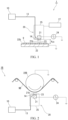
FIG. 1 is a configuration diagram schematically illustrating a surface modification device according to the first embodiment of the present invention. -
FIG. 2 is a configuration diagram schematically illustrating a surface modification device according to the second embodiment of the present invention. -
FIG. 3 is a configuration diagram schematically illustrating a surface modification device according to the third embodiment of the present invention. -
FIG. 4 is a graph showing the results of the measurement of the peel strength depending on the amount of energy input per unit area in Examples. -
FIG. 5 is a spectrum diagram produced by infrared spectroscopic analysis in Examples. - In the following, embodiments of the present invention will be described with reference to drawings.
-
FIG. 1 illustrates asurface modification device 1 according to the first embodiment of the present invention. Atreatment target 9 is a hard-to-adhere material containing fluorine atoms. Examples of such a hard-to-adhere material include fluorine-based resins such as polytetrafluoroethylene (PTFE) and ethylene tetrafluoroethylene (ETFE). The shape of thetreatment target 9 is not particularly limited, and may be, for example, a film shape, a plate shape, or a block shape. - The
surface modification device 1 modifies the surface of thetreatment target 9 made of the hard-to-adhere material to improve adhesiveness, and includes a processgas supply unit 10 and aplasma generation unit 20. The processgas supply unit 10 supplies a process gas to theplasma generation unit 20. The process gas contains any one or two or more among carbon monoxide, carbon dioxide, hydrogen, water vapor, ethanol, propanol, hexanol, ethylene glycol, and ammonia as an additive component. - The additive component is added to a carrier gas to yield the process gas. As an addition means, a mass flow controller (MFC) may be used, or bubbling may be used.
- Examples of the carrier gas include an inert gas such as nitrogen (N2). As the carrier gas, a noble gas may be used instead of nitrogen. The carrier gas serves as a carrier gas that conveys the process gas containing the additive component to the
plasma generation unit 20 and thetreatment target 9, and also serves as a dilution gas that dilutes the additive component and as a discharge generation gas in theplasma generation unit 20. - The
plasma generation unit 20 includes a pair ofelectrodes plasma head 25. Thehot electrode 21 is accommodated in theplasma head 25. Thehot electrode 21 is formed in an elongated plate shape extending in a treating width direction orthogonal to the plane ofFIG. 1 . The dimension of thehot electrode 21 in the treating width direction is substantially equal to or slightly larger than the treating width (the dimension in a direction orthogonal to the plane ofFIG. 1 ) of thetreatment target 9. Theground electrode 22 is disposed below theplasma head 25. Theground electrode 22 is formed in a flat plate shape (stage shape) that is a quadrangle in plan view having a dimension in the treating width direction equivalent to that of thehot electrode 21. Theseelectrodes electrodes dielectric layers dielectric layers - An
interelectrode space 23 is defined between theelectrodes electrodes interelectrode space 23 is near the atmospheric pressure. The gap g23 of the interelectrode space 23 (the distance between the opposing surfaces of the soliddielectric layers treatment target 9, and preferably is several mm or less. InFIG. 1 , the size of the gap g23 is exaggerated. - A
power source 24 is connected to thehot electrode 21. Theground electrode 22 is electrically grounded. - The
power source 24 converts a commercial AC power into a DC power, further converts the DC power into a pulsed high-frequency power, and supplies the high-frequency power to theelectrode 21. The peak-to-peak voltage of a pulse wave-like voltage to be applied between the pair ofelectrodes 21 is preferably 3 kVpp to 25 kVpp, and more preferably 10 kVpp to 16 kVpp. The frequency of the pulse wave-like voltage is preferably 20 kHz to 55 kHz, and more preferably 40 kHz to 50 kHz. - A
gas supply line 13 from the processgas supply unit 10 extends to theplasma generation unit 20. Anozzle 14 disposed at the tip of thegas supply line 13 is held in theplasma head 25 and faces theinterelectrode space 23. Although not shown in detail in the drawings, thenozzle 14 includes a gas diffusion unit that uniformly diffuses the gas from thegas supply line 13 in the treating width direction (the direction orthogonal to the plane inFIG. 1 ). - The
treatment target 9 is placed on the stage-shapedground electrode 22. Theground electrode 22 also serves as a support portion for thetreatment target 9. Thetreatment target 9 is supported by theground electrode 22 as the support portion such that thetreatment target 9 comes into contact with the gas in theinterelectrode space 23. - The
surface modification device 1 constitutes a direct plasma treating apparatus. In the present description, direct plasma treatment refers to surface treatment in which atreatment target 9 is directly exposed to plasma discharge in aninterelectrode space 23 by disposing thetreatment target 9 in theinterelectrode space 23 or passing thetreatment target 9 through in theinterelectrode space 23. - A
movement mechanism 27 is connected to theplasma head 25 and thus thehot electrode 21. Although not shown in detail in the drawings, themovement mechanism 27 includes a drive means such as a motor, and a power transmission means such as a gear and a timing belt. By themovement mechanism 27, thehot electrode 21 and theground electrode 22 and thus thetreatment target 9 are relatively moved to reciprocate in a scanning direction (left-right direction inFIG. 1 ) orthogonal to the treating width direction. - The
movement mechanism 27 may be connected to theground electrode 22. Theground electrode 22 may be moved with respect to theplasma head 25. - The
treatment target 9 is subjected to surface modification (surface treatment) by thesurface modification device 1 as follows. - A plasma step and a modification step are performed using the
surface modification device 1. In the plasma step, the process gas is activated by plasma and brought into contact with thetreatment target 9. Specifically, the plasma step includes a generation step, a supply step, a contact step, and a movement step. - A pulse wave-like voltage is applied between the pair of
electrodes power source 24. As a result, a pulsed electric field is applied into theinterelectrode space 23, and plasma discharge (dielectric barrier discharge) near the atmospheric pressure is generated. Preferably, a pulsed plasma near the atmospheric pressure is generated. - In parallel, the process gas from the process
gas supply unit 10 is supplied to theinterelectrode space 23 via thesupply line 13 and through thenozzle 14. - Through this step, the process gas is activated (including plasmatization, excitation, decomposition, radicalization, and ionization) in the interelectrode space 23 (plasma discharge space). The activated process gas is brought into contact with the
treatment target 9. - Furthermore, the
hot electrode 21 is moved in the scanning direction (the left-right direction inFIG. 1 ) by themovement mechanism 27. As a result, while thetreatment target 9 is relatively moved to pass through in theinterelectrode space 23, thetreatment target 9 comes into contact with an activated process gas and is directly exposed to plasma near the atmospheric pressure (atmospheric pressure direct plasma step). Preferably, it is directly exposed to pulsed plasma near the atmospheric pressure (atmospheric pressure direct pulse plasma step). - The number of treatment, n, for each relative one-way movement of the
treatment target 9 in theinterelectrode space 23 is not limited to one, and may be a plurality of times. Thetreatment target 9 may be reciprocated and thereby treated twice per reciprocation. In another adoptable embodiment, a plurality of plasma heads 25 each including ahot electrode 21 are provided, atreatment target 9 passes successively through interelectrode spaces formed by the respective plasma heads 25, and, as a result, the number of the plasma heads 25 corresponds to the number of the times of treatment. - The amount of energy input in the plasma step is preferably 0.9 J/cm2 to 135.0 J/cm2 per unit area of the surface of the
treatment target 9. When the process gas contains carbon monoxide, carbon dioxide, water vapor, ethanol, propanol, hexanol, ethylene glycol, or ammonia as an additive component, the amount of energy input is more preferably about 5 J/cm2 to 60 J/cm2, and still more preferably about 10 J/cm2 to 30 J/cm2. When the process gas contains hydrogen as an additive component, the amount of energy input is more preferably about 30 J/cm2 to 120 J/cm2, and still more preferably about 40 J/cm2 to 80 J/cm2 (seeFIG. 4 and Examples described later). - The amount of energy input per unit area, E, of the surface of the
treatment target 9 is given by the following formula (1).
- The input power (W) is determined by the product of the DC voltage (V) and the DC current (A) before the high-frequency conversion in the
power source 24. - As described above, when the
treatment target 9 is moved relative to one or a plurality of plasma heads 25 and treated n times, the amount of energy input per unit area, E, is given by the following formula (2).
- Pi is the input power (W/cm) per unit treating width (unit length in the direction orthogonal to the plane of
FIG. 1 ) when thetreatment target 9 is treated for the i-th time. - vi is the relative movement speed (cm/sec) of the
treatment target 9 for the i-th time. - In each time of treatment, on a surface of the
treatment target 9, a reaction occurs due to the contact between the surface molecules of thetreatment target 9 and the plasma and the activated process gas. As a result, a fluorine bond in a surface molecule of thetreatment target 9 is broken, and a fluorine atom is separated from the surface molecule. Therefore, the proportion (atom%) of fluorine atoms among the atoms constituting the surface of thetreatment target 9 decreases. Further, a carbon atom, a hydrogen atom, an oxygen atom, and the like derived from the process gas or the atmospheric gas (air) are bonded to the bond made free by the breakage. In this manner, the residual ratio of fluorine atoms on the surface of thetreatment target 9 is adjusted to 60% or less of that before the contact (untreated), and any one among a carbon atom, a hydrogen atom, and an oxygen atom, or a molecule containing one or more of them is provided to the surface of thetreatment target 9. By adjusting the amount of energy input E or the like, the residual ratio of fluorine atoms can be reliably brought within the above preferred range. - As a result, a hydrophilic layer is formed on the surface of the
treatment target 9, whereby the contact angle of thetreatment target 9 with respect to water decreases, the wettability is improved, and the adhesiveness is improved. In other words, the surface of thetreatment target 9 is modified. - Next, other embodiments of the present invention will be described. In the following embodiments, the same reference numerals are given to the drawings and the description thereof will be omitted for the configurations overlapping with the above-described embodiment.
-
FIG. 2 illustrates the second embodiment of the present invention. Thesurface modification device 1B in the second embodiment is an atmospheric pressure direct plasma treating apparatus including an elongated flat plate-shapedhot electrode 21 and a rolled (cylindrical)ground electrode 22B (hereinafter referred to as "roll electrode 22B") as a pair of electrodes. Apower source 24 is connected to thehot electrode 21, and theroll electrode 22B is electrically grounded. - A
plasma head 25 including thehot electrode 21 and anozzle 14 is disposed below theroll electrode 22B. Theroll electrode 22B and thehot electrode 21 face each other with aninterelectrode space 23 interposed therebetween. The longitudinal direction of thehot electrode 21 and the axis of theroll electrode 22B are oriented in the treating width direction (the direction orthogonal to the plane ofFIG. 2 ). - In
FIG. 2 , the gap between theelectrodes - Although not illustrated, a solid dielectric layer is formed on the outer peripheral surface of the
roll electrode 22B. - The
plasma head 25 may be disposed above theroll electrode 22B. - The
treatment target 9B in the second embodiment is a continuous film made of a hard-to-adhere material containing a fluorine atom, such as a PTFE film or an ETFE film. Thetreatment target 9B is wound about half round on a peripheral surface portion on the lower side (the side facing the electrode 21) of theroll electrode 22B. Thus, thetreatment target 9B is passed through theinterelectrode space 23. - The
roll electrode 22B is rotated about its own axis. Thus, thetreatment target 9B is conveyed in a substantially right direction inFIG. 2 . Theroll electrode 22B serves as both a support portion and a movement mechanism for thetreatment target 9B. - In parallel, a pulse plasma near the atmospheric pressure is generated in the
interelectrode space 23 by the application of the high-frequency pulse voltage from thepower source 21. Further, a process gas is supplied through thenozzle 14 to theinterelectrode space 23 and is activated. By bringing the plasma and the activated process gas into contact with thetreatment target 9B, thetreatment target 9B is surface-modified, and the adhesiveness is improved. - With the
device 1B of the second embodiment, conveying the film-shapedtreatment target 9B in contact with theroll electrode 22B can prevent thetreatment target 9B from being damaged. In addition, by making a surface of thetreatment target 9B intended to be treated face the front side, only the surface intended to be treated can be treated by applying plasma. The surface intended not to be treated can be prevented from being treated by making the surface intended not to be treated face the back side and bringing the surface in contact theroll electrode 22B. Furthermore, the treating region can be enlarged by increasing the number of the pair of theelectrodes -
FIG. 3 illustrates the third embodiment of the present invention. - The surface modification device 1C of the third embodiment constitutes an atmospheric pressure remote plasma treating apparatus. In the present description, remote plasma treatment refers to surface treatment in which a treatment target is disposed away from an interelectrode space (a plasma discharge space) and the plasma generated from the interelectrode space and the treatment target are brought into contact with each other outside the interelectrode space.
- Specifically, the surface modification device 1C includes a
plasma head 20C (plasma generation unit) and astage 28. Theplasma head 20C includes therein a pair of ahot electrode 21C and a ground electrode 22C held to face each other in the left-right direction. Apower source 24 is connected to thehot electrode 21C. The ground electrode 22C is electrically grounded. The pair ofelectrodes 21C and 22C are both formed in a flat plate shape and constitute a parallel plate electrode, but are not limited thereto, and may be in a coaxial cylindrical shape. - An
interelectrode space 23 is formed between the pair ofelectrodes 21C and 22C facing each other. Agas supply line 13 is connected to an upper end portion of theinterelectrode space 23. - A
nozzle 26 including a ceramic plate or the like is provided at a lower end portion of theplasma head 20C. A lower end portion of theinterelectrode space 23 is connected to thenozzle 26. - A
stage 28 is disposed below theplasma head 20C. Atreatment target 9 is placed on the upper surface of thestage 28. Thestage 28 constitutes a support portion that supports the treatment target such that the treatment target comes into contact with the process gas after passing through theinterelectrode space 23. - In the surface modification device 1C, the process gas from the process
gas supply unit 10 is introduced into theinterelectrode space 23 and activated. - The activated process gas is blown downward through the
nozzle 26 and comes into contact with thetreatment target 9. Thus, the surface of thetreatment target 9 is modified. - Furthermore, the
plasma head 20C is moved with respect to thestage 28, whereby the entire region of thetreatment target 9 is treated. - The
stage 28 may be moved with respect to theplasma head 20C. - The present invention is not limited to the embodiments described above, and various modifications can be made without departing from the gist thereof.
- For example, the discharge form for forming plasma is preferably glow discharge, but may be corona discharge, streamer discharge, arc discharge, or other various discharge forms. In addition, an electrode shape in which a dielectric barrier is provided between discharge electrodes is preferable.
- The plasma is not limited to one formed by discharge at the atmospheric pressure, and may be one formed by discharge under vacuum.
- Next, examples will be described. The present invention is not limited to the following examples.
- In Example 1, an atmospheric pressure direct plasma apparatus including a parallel plate electrode was prepared.
- The hard-to-adhere material of the treatment target was film-shaped PTFE. The atomic composition of the surface of the blank (untreated) treatment target was fluorine (F) 67.6 atom% and carbon (C) 32.4 atom%.
- The treatment target was placed on the
lower ground electrode 22 of the pair of electrodes forming the parallel plate electrode, and was opposed to the upperhot electrode 21. - The process gas contained nitrogen (N2) as a carrier gas, and carbon monoxide (CO) was added thereto as an additive component. The amount of carbon monoxide added was 5 L/min.
- The total flow rate of the process gas was 50 L/min.
- The process gas was supplied to the interelectrode space, a pulsed high-frequency electric field was applied to between the electrodes to generate atmospheric pressure pulse plasma between the electrodes, and the treatment target was irradiated with the plasma. Further, the process gas activated by the plasma was brought into contact with the treatment target.
- The amount of energy input per unit area was adjusted by varying the DC power before high-frequency conversion in the
power source 24. The amount of energy input per unit area when the peel strength described later reached the maximum was E = 11.3 J/cm2. - The pulse wave-like voltage applied had a peak-to-peak voltage of 17 kVpp and a frequency of 50 kHz.
- After the treatment, the atomic composition of the surface of the treatment target was analyzed by X-ray photoelectron spectroscopy (XPS). As an analyzer, a spectrometer PHI5000 VersaProbe II manufactured by ULVAC-PHI, Inc. was used.
- As shown in Table 1, the analysis results were fluorine (F) 5.5 atom%, carbon (C) 45.3 atom%, nitrogen (N) 28.9 atom%, and oxygen (O) 20.2 atom%.
- Therefore, the residual ratio of fluorine atoms on the surface of the treatment target after the treatment relative to the untreated state (before the treatment) was (5.5/67.6) = 8.2%.
- It is considered that the nitrogen (N) in the surface atomic composition was derived from nitrogen molecules (N2) in the carrier gas and the air.
- In addition, although hydrogen (H) cannot be detected by XPS, as hydrophilicity was enhanced after the treatment, it is presumed that a hydrogen atom-containing group such as OH, NH or CH derived from a hydrogen-containing molecule such as water vapor (H2O) in the air was provided to the surface of the treatment target.
- Actually, when the treatment target was subjected to infrared light analysis, hydrogen atom-containing groups such as OH and NH were confirmed as shown in
FIG. 5(a) . - As an infrared spectroscopic analyzer, Nicolet iN10MX manufactured by Thermo Scientific was used.
- As evaluation, two film pieces were cut out from the treatment target film after the treatment, these film pieces were bonded together, and then the peel strength was measured by a peeling test.
- An acrylic adhesive was used as an adhesive (pressure-sensitive adhesive).
- The peel test was a T-peel test in accordance with JIS K 6854-3.
- The peel strength in the peel test was evaluated in three grades (see
FIG. 4 ) where the peel strength of an untreated sample was defined as 1; a peel strength 2.5 times or more of that of the untreated sample was rated as excellent (⊙); a peel strength 1.5 times or more and less than 2.5 times of that of the untreated sample was rated as good (O); and a peel strength 1.5 times or less of that of the untreated sample was rated as poor (×). As a result, the peel strength was excellent (⊙). - In Example 2, carbon dioxide (CO2) was used as an additive component of the process gas.
- The added amount was 10 L/min.
- The amount of energy input per unit area when the peel strength described later reached the maximum was E = 32.3 J/cm2.
- Other treatment conditions, and analysis and evaluation after treatment were the same as those in Example 1.
- As shown in Table 1, the atomic composition ratio of the surface of the treatment target after the treatment was, according to the XPS analysis, fluorine (F) 38.3 atom%, carbon (C) 43.6 atom%, nitrogen (N) 9.9 atom%, and oxygen (O) 8.2 atom%.
- Therefore, the residual ratio of fluorine atoms on the surface of the treatment target after the treatment relative to the untreated state (before the treatment) was (38.3/67.6) = 57.4%.
- In addition, as hydrophilicity was enhanced after the treatment, it is presumed that a hydrogen atom-containing group such as OH, NH or CH was provided to the surface of the treatment target.
- The peel strength measured by the peel test was good (O).
[Table 1] Untreated PTFE Example 1 Example 2 Discharge form - Dielectric barrier discharge Dielectric barrier discharge Hard-to-adhere material PTFE PTFE PTFE Carrier gas - N2 N2 Total flow rate - 50 L/min 50 L/min Additive - Carbon monoxide Carbon dioxide Added amount - 5 L/min 10 L/min E [J/cm2] - 11.3 32.3 F [atom%] 67.6 5.5 38.3 C [atom%] 32.4 45.3 43.6 N [atom%] - 28.9 9.9 O [atom%] - 20.2 8.2 F residual ratio [%] - 8.2 57.4 Peel strength × ⊙ ○ - As Comparative Example 1, the process gas was nitrogen (N2) 100%. That is, no additive component was used.
- The flow rate of the process gas (N2) was 50 L/min.
- The amount of energy input per unit area when the peel strength described later reached the maximum was E = 10.35 J/cm2.
- Other treatment conditions, and analysis and evaluation after treatment were the same as those in Example 1.
- As shown in Table 2, the atomic composition ratio of the surface of the treatment target after the treatment was, according to the XPS analysis, fluorine (F) 61 atom%, carbon (C) 35.1 atom%, nitrogen (N) 2.4 atom%, and oxygen (O) 1.5 atom%.
- Therefore, the residual ratio of fluorine atoms on the surface of the treatment target after the treatment relative to the untreated state (before the treatment) was (61/67.6) = 91.5%.
- The peel strength measured by the peel test was poor (×).
- In Comparative Example 2, oxygen (O2) was used as an additive component of the process gas.
- The added amount was 0.05 L/min.
- The amount of energy input per unit area when the peel strength described later reached the maximum was E = 10.35 J/cm2.
- Other treatment conditions, and analysis and evaluation after treatment were the same as those in Example 1.
- As shown in Table 2, the atomic composition ratio of the surface of the treatment target after the treatment was, according to the XPS analysis, fluorine (F) 60.3 atom%, carbon (C) 36.1 atom%, nitrogen (N) 2.4 atom%, and oxygen (O) 1.2 atom%.
- Therefore, the residual ratio of fluorine atoms on the surface of the treatment target after the treatment relative to the untreated state (before the treatment) was (60.3/67.6) = 90.4%.
- The peel strength measured by the peel test was poor (×).
[Table 2] Comparative Example 1 Comparative Example 2 Discharge form Dielectric barrier discharge Dielectric barrier discharge Hard-to-adhere material PTFE PTFE Carrier gas N2 N2 Total flow rate 50 L/min 50 L/min Additive - Oxygen Added amount - 0.05 L/min E [J/cm2] 10.35 10.35 F [atom%] 61 60.3 C [atom%] 35.1 36.1 N [atom%] 2.4 2.4 O [atom%] 1.5 1.2 F residual ratio [%] 91.5 90.4 Peel strength × × - In Example 3, hydrogen (H2) was used as an additive component of the process gas.
- The added amount was 2 L/min.
- The amount of energy input per unit area when the peel strength described later reached the maximum was E = 56.3 J/cm2.
- Other treatment conditions, and analysis and evaluation after treatment were the same as those in Example 1.
- As shown in Table 3, the atomic composition ratio of the surface of the treatment target after the treatment was, according to the XPS analysis, fluorine (F) 37.3 atom%, carbon (C) 50.9 atom%, nitrogen (N) 6.5 atom%, and oxygen (O) 5.4 atom%.
- Therefore, the residual ratio of fluorine atoms on the surface of the treatment target after the treatment relative to the untreated state (before the treatment) was (37.3/67.6) = 55.9%.
- It is considered that the oxygen (O) in the surface atomic composition was derived from oxygen molecules (O2) or carbon dioxide (CO2) in the air as an atmospheric gas. It is considered that the nitrogen (N) was derived from nitrogen molecules (N2) in the carrier gas and the air.
- In addition, although hydrogen (H) cannot be detected by XPS, as hydrophilicity was enhanced after the treatment, it is presumed that a hydrogen atom-containing group such as OH, NH or CH was provided to the surface of the treatment target.
- The peel strength measured by the peel test was excellent (⊙).
- In Example 4, water vapor (H2O) was used as an additive component of the process gas.
- The added amount was 2.17 g/min.
- The amount of energy input per unit area when the peel strength described later reached the maximum was E = 7 J/cm2.
- Other treatment conditions, and analysis and evaluation after treatment were the same as those in Example 1.
- As shown in Table 3, the atomic composition ratio of the surface of the treatment target after the treatment was, according to the XPS analysis, fluorine (F) 28.3 atom%, carbon (C) 55.6 atom%, nitrogen (N) 9.6 atom%, and oxygen (O) 6.5 atom%.
- Therefore, the residual ratio of fluorine atoms on the surface of the treatment target after the treatment relative to the untreated state (before the treatment) was (28.3/67.6) = 42.4%.
- In addition, as hydrophilicity was enhanced after the treatment, it is presumed that a hydrogen atom-containing group such as OH, NH or CH was provided to the surface of the treatment target.
- The peel strength measured by the peel test was good (O).
- In Example 5, ethanol (C2H5OH) was used as an additive component of the process gas.
- The added amount was 5.5 g/min.
- The amount of energy input per unit area when the peel strength described later reached the maximum was E = 11.3 J/cm2.
- Other treatment conditions, and analysis and evaluation after treatment were the same as those in Example 1.
- As shown in Table 3, the atomic composition ratio of the surface of the treatment target after the treatment was, according to the XPS analysis, fluorine (F) 5 atom%, carbon (C) 56.1 atom%, nitrogen (N) 19.4 atom%, and oxygen (O) 19.5 atom%.
- Therefore, the residual ratio of fluorine atoms on the surface of the treatment target after the treatment relative to the untreated state (before the treatment) was (5/67.6) = 7.5%.
- In addition, as hydrophilicity was enhanced after the treatment, it is presumed that a hydrogen atom-containing group such as OH, NH or CH was provided to the surface of the treatment target.
- As a result of infrared light analysis, hydrogen atom-containing groups such as OH, NH, and CH were actually confirmed as shown in
FIG. 5(b) . - The peel strength measured by the peel test was excellent (⊙).
[Table 3] Example 3 Example 4 Example 5 Discharge form Dielectric barrier discharge Dielectric barrier discharge Dielectric barrier discharge Hard-to-adhere material PTFE PTFE PTFE Carrier gas N2 N2 N2 Total flow rate 50 L/min 50 L/min 50 L/min Additive Hydrogen Water vapor Ethanol Added amount 2 L/min 2.17 g/min 5.5 g/min E [J/cm2] 56.3 7 11.3 F [atom%] 37.3 28.3 5 C [atom%] 50.9 55.6 56.1 N [atom%] 6.5 9.6 19.4 O [atom%] 5.4 6.5 19.5 F residual ratio [%] 55.9 42.4 7.5 Peel strength ⊙ ○ ⊙ -
FIG. 4 shows the relationship between the amount of energy input per unit area (J/cm2) and the peel strength for each additive component. - When the amount of energy input per unit area, E, is E = 0.9 J/cm2 to 135.0 J/cm2, it can be said that the peel strength is improved and the surface modification effect is acquired.
- In Example 6, propanol (C3H7OH) was used as an additive component of the process gas.
- The added amount was 2.5 g/min.
- The amount of energy input per unit area when the peel strength described later reached the maximum was E = 5.11 J/cm2.
- Other treatment conditions, and analysis and evaluation after treatment were the same as those in Example 1.
- As shown in Table 4, the atomic composition ratio of the surface of the treatment target after the treatment was, according to the XPS analysis, fluorine (F) 14 atom%, carbon (C) 54 atom%, nitrogen (N) 16.5 atom%, and oxygen (O) 15.5 atom%.
- Therefore, the residual ratio of fluorine atoms on the surface of the treatment target after the treatment relative to the untreated state (before the treatment) was (14/67.6) = 21%.
- In addition, as hydrophilicity was enhanced after the treatment, it is presumed that a hydrogen atom-containing group such as OH, NH or CH was provided to the surface of the treatment target.
- The peel strength measured by the peel test was excellent (⊙).
- In Example 7, hexanol (CH3(CH2)5OH) was used as an additive component of the process gas.
- The added amount was 0.3 g/min.
- The amount of energy input per unit area when the peel strength described later reached the maximum was E = 5.11 J/cm2.
- Other treatment conditions, and analysis and evaluation after treatment were the same as those in Example 1.
- As shown in Table 4, the atomic composition ratio of the surface of the treatment target after the treatment was, according to the XPS analysis, fluorine (F) 16 atom%, carbon (C) 56.3 atom%, nitrogen (N) 13.6 atom%, and oxygen (O) 14.1 atom%.
- Therefore, the residual ratio of fluorine atoms on the surface of the treatment target after the treatment relative to the untreated state (before the treatment) was (16/67.6) = 24.0%.
- In addition, as hydrophilicity was enhanced after the treatment, it is presumed that a hydrogen atom-containing group such as OH, NH or CH was provided to the surface of the treatment target.
- The peel strength measured by the peel test was good (O).
- In Example 8, ethylene glycol (C2H6O2) was used as an additive component of the process gas.
- The added amount was 6 mg/min.
- The amount of energy input per unit area when the peel strength described later reached the maximum was E = 5.11 J/cm2.
- Other treatment conditions, and analysis and evaluation after treatment were the same as those in Example 1.
- As shown in Table 4, the atomic composition ratio of the surface of the treatment target after the treatment was, according to the XPS analysis, fluorine (F) 20 atom%, carbon (C) 55.9 atom%, nitrogen (N) 12.3 atom%, and oxygen (O) 11.8 atom%.
- Therefore, the residual ratio of fluorine atoms on the surface of the treatment target after the treatment relative to the untreated state (before the treatment) was (20/67.6) = 30.0%.
- In addition, as hydrophilicity was enhanced after the treatment, it is presumed that a hydrogen atom-containing group such as OH, NH or CH was provided to the surface of the treatment target.
- The peel strength measured by the peel test was good (O).
- In Example 9, ammonia (NH3) was used as an additive component of the process gas.
- The added amount was 2.17 g/min.
- The amount of energy input per unit area when the peel strength described later reached the maximum was E = 2.05 J/cm2.
- Other treatment conditions, and analysis and evaluation after treatment were the same as those in Example 1.
- As shown in Table 4, the atomic composition ratio of the surface of the treatment target after the treatment was, according to the XPS analysis, fluorine (F) 33.3 atom%, carbon (C) 52.3 atom%, nitrogen (N) 7 atom%, and oxygen (O) 7.4 atom%.
- Therefore, the residual ratio of fluorine atoms on the surface of the treatment target after the treatment relative to the untreated state (before the treatment) was (33.3/67.6) = 49.9%.
- In addition, as hydrophilicity was enhanced after the treatment, it is presumed that a hydrogen atom-containing group such as OH, NH or CH was provided to the surface of the treatment target.
- The peel strength measured by the peel test was good (O).
[Table 4] Example 6 Example 7 Example 8 Example 9 Discharge form Dielectric barrier discharge Dielectric barrier discharge Dielectric barrier discharge Dielectric barrier discharge Hard-to-adhere material PTFE PTFE PTFE PTFE Carrier gas N2 N2 N2 N2 Total flow rate 50 L/min 50 L/min 50 L/min 50 L/min Additive Propanol Hexanol Ethylene glycol Ammonia Added amount 2.5 g/min 0.3 g/min 6 mg/min 2.17 g/min E [J/cm2] 5.11 5.11 5.11 2.05 F [atom%] 14 16 20 33.3 C [atom%] 54 56.3 55.9 52.3 N [atom%] 16.5 13.6 12.3 7 O [atom%] 15.5 14.1 11.8 7.4 F residual ratio [%] 21.0 24.0 30.0 49.9 Peel strength ⊙ ○ ○ ○ - In Example 10, a corona discharge device including a parallel plate electrode was prepared.
- The hard-to-adhere material of the treatment target was film-shaped PTFE.
- The treatment target was placed on the lower ground electrode of the pair of electrodes forming the parallel plate electrode, and was opposed to the upper hot electrode.
- The additive component of the process gas was ethanol. The added amount was 5.5 g/min.
- The carrier gas of the process gas was nitrogen (N2), and the total flow rate of the process gas was 50 L/min.
- The process gas was supplied to the interelectrode space, corona discharge was generated between the electrodes under the atmospheric pressure, and the surface of the treatment target was directly exposed to the corona discharge. The process gas activated by the corona discharge was brought into contact with the treatment target.
- The amount of energy input per unit area when the peel strength described later reached the maximum was E = 4.94 J/cm2.
- After the treatment, the measurement of the atomic composition of the surface of the treatment target, the calculation of the residual ratio of fluorine atoms, and the evaluation of the peel strength were performed in the same manner as in Example 1.
- As shown in Table 5, the atomic composition ratio of the surface of the treatment target after the treatment was, according to the XPS analysis, fluorine (F) 26 atom%, carbon (C) 49.3 atom%, nitrogen (N) 12.1 atom%, and oxygen (O) 12.6 atom%.
- Therefore, the residual ratio of fluorine atoms on the surface of the treatment target after the treatment relative to the untreated state (before the treatment) was (26/67.6) = 38.5%.
- In addition, as hydrophilicity was enhanced after the treatment, it is presumed that a hydrogen atom-containing group such as OH, NH or CH was provided to the surface of the treatment target.
- The peel strength measured by the peel test was good (O).
- As a comparative example, the same corona treatment as in Example 10 was performed using a process gas with a total flow rate of 50 L/min obtained by adding 20 vol% of air to a carrier gas (N2).
- The amount of energy input per unit area when the peel strength described later reached the maximum was E = 4.94 J/cm2.
- As shown in Table 5, the atomic composition ratio of the surface of the treatment target after the treatment was, according to the XPS analysis, fluorine (F) 63.6 atom%, carbon (C) 32.6 atom%, nitrogen (N) 2.6 atom%, and oxygen (O) 1.2 atom%.
- Therefore, the residual ratio of fluorine atoms on the surface of the treatment target after the treatment relative to the untreated state (before the treatment) was (63.6/67.6) = 94.1%.
- The peel strength measured by the peel test was poor (×).
- In Example 11, film-shaped ETFE was applied as a hard-to-adhere material of a treatment target. The atomic composition of the surface of the blank (untreated) ETFE was fluorine (F) 48.9 atom% and carbon (C) 51.1 atom%.
- The same plasma treating apparatus as that used in Example 1 was used as a treating apparatus.
- The additive component of the process gas was ethanol (C2H5OH), and the added amount was 2.17 g/min.
- The carrier gas of the process gas was nitrogen (N2), and the total flow rate of the process gas was 50 L/min.
- The process gas was supplied to the interelectrode space, atmospheric pressure plasma was generated between the electrodes, and the surface of the treatment target was directly exposed to the plasma. Further, the process gas activated by the plasma was brought into contact with the treatment target.
- The amount of energy input per unit area was E = 32.3 J/cm2.
- After the treatment, the measurement of the atomic composition of the surface of the treatment target, the calculation of the residual ratio of fluorine atoms, and the evaluation of the peel strength were performed in the same manner as in Example 1.
- As shown in Table 5, the atomic composition ratio of the surface of the treatment target after the treatment was, according to the XPS analysis, fluorine (F) 4.9 atom%, carbon (C) 67 atom%, nitrogen (N) 16.6 atom%, and oxygen (O) 11.5 atom%.
- Therefore, the residual ratio of fluorine atoms on the surface of the treatment target after the treatment relative to the untreated state (before the treatment) was (4.9/48.9) = 10.0%.
- In addition, as hydrophilicity was enhanced after the treatment, it is presumed that a hydrogen atom-containing group such as OH, NH or CH was provided to the surface of the treatment target.
- The peel strength measured by the peel test was excellent (⊙).
[Table 5] Example 10 Comparative Example 3 Example 11 Untreated ETFE Discharge form Corona discharge Corona discharge Dielectric barrier discharge - Hard-to-adhere material PTFE PTFE ETFE ETFE Carrier gas N2 N2 N2 - Total flow rate 50 L/min 50 L/min 50 L/min - Additive Ethanol Air Ethanol - Added amount 5.5 g/ min 20 vol% 2.17 g/min - E [J/cm2] 4.94 4.94 32.3 - F [atom%] 26 63.6 4.9 48.9 C [atom%] 49.3 32.6 67 51.1 N [atom%] 12.1 2.6 16.6 - O [atom%] 12.6 1.2 11.5 - F residual ratio [%] 38.5 94.1 10.0 - Peel strength ○ × ⊙ × - From the Examples disclosed above, it has been found that using the method of the present invention, a good surface modification effect can be acquired through setting the conditions such that the residual ratio of fluorine atoms on a surface of a treatment target after treatment is about 60% or less. It has been found that, depending on the type of the additive component of the process gas, or the like, a more favorable surface modification effect can be acquired through setting the conditions such that the residual ratio is preferably about 20% or less, and more preferably about 10% or less.
- The present invention can be applied to treatment for improving the wettability of fluorine-based hard-to-adhere materials such as PTFE and ETFE.
-
- 1
- surface modification device
- 1B, 1C
- surface modification device
- 9, 9B
- Hard-to-adhere resin film (treatment target)
- 10
- process gas generation unit
- 13
- gas supply line
- 14
- nozzle
- 20
- plasma generation unit
- 20C
- plasma head (plasma generation unit)
- 21b
- solid dielectric layer
- 22b
- solid dielectric layer
- 21, 21C
- hot electrode (electrode)
- 22
- ground electrode (electrode, support portion)
- 22B
- roll electrode (electrode, support portion)
- 22C
- ground electrode (electrode)
- 23
- interelectrode space (plasma discharge space)
- 24
- power source
- 25
- plasma head
- 27
- movement mechanism
- 28
- stage (support portion)
Claims (7)
- A method for surface-modifying a treatment target made of a hard-to-adhere material containing a fluorine atom, the method comprising:a plasma step of activating a process gas containing any one or two or more among carbon monoxide, carbon dioxide, hydrogen, water vapor, ethanol, propanol, hexanol, ethylene glycol, and ammonia by plasma and bringing the process gas into contact with the treatment target; anda modification step of, through a reaction caused by the contact, adjusting a residual ratio of fluorine atoms on a surface of the treatment target to 60% or less of a residual ratio before the contact and providing any one among a carbon atom, a hydrogen atom and an oxygen atom or a molecule containing one or more of these atoms to the surface of the treatment target.
- The surface modification method according to claim 1, wherein
the plasma step includes:a generation step of generating plasma discharge near atmospheric pressure by applying an electric field to an interelectrode space defined by a pair of electrodes,a supply step of supplying the process gas to the interelectrode space, anda contact step of bringing the process gas in the interelectrode space or having passed through the interelectrode space into contact with the treatment target. - The surface modification method according to claim 2, wherein an amount of energy input in the plasma step is 0.9 J/cm2 to 135.0 J/cm2 per unit area of the surface of the treatment target.
- The surface modification method according to claim 3, wherein the plasma step includes a step in which the treatment target passes through in the interelectrode space.
- The surface modification method according to any one of claims 2 to 4, wherein a peak-to-peak voltage of a voltage applied to between the pair of electrodes is 3 kVpp to 25 kVpp, and a frequency is 10 kHz to 70 kHz.
- The surface modification method according to any one of claims 2 to 5, whereinthe treatment target has a film shape,the pair of electrodes includes a roll-shaped ground electrode and a hot electrode disposed facing the ground electrode, andin the plasma step, the treatment target is conveyed in contact with the ground electrode, and the plasma near the atmospheric pressure is generated between the ground electrode and the hot electrode.
- The surface modification method according to any one of claims 2 to 6,
wherein the plasma step includes a step of applying a pulse wave-like voltage to between the pair of electrodes to generate pulse plasma near atmospheric pressure in the interelectrode space.
Applications Claiming Priority (2)
| Application Number | Priority Date | Filing Date | Title |
|---|---|---|---|
| JP2021042106 | 2021-03-16 | ||
| PCT/JP2022/011062 WO2022196580A1 (en) | 2021-03-16 | 2022-03-11 | Surface modification method |
Publications (2)
| Publication Number | Publication Date |
|---|---|
| EP4311376A1 true EP4311376A1 (en) | 2024-01-24 |
| EP4311376A4 EP4311376A4 (en) | 2025-04-02 |
Family
ID=83320644
Family Applications (1)
| Application Number | Title | Priority Date | Filing Date |
|---|---|---|---|
| EP22771328.6A Pending EP4311376A4 (en) | 2021-03-16 | 2022-03-11 | SURFACE MODIFICATION PROCESSES |
Country Status (7)
| Country | Link |
|---|---|
| US (1) | US20240162018A1 (en) |
| EP (1) | EP4311376A4 (en) |
| JP (1) | JPWO2022196580A1 (en) |
| KR (1) | KR20230157402A (en) |
| CN (1) | CN116997599A (en) |
| TW (1) | TW202244150A (en) |
| WO (1) | WO2022196580A1 (en) |
Family Cites Families (11)
| Publication number | Priority date | Publication date | Assignee | Title |
|---|---|---|---|---|
| JPH06228343A (en) | 1993-02-08 | 1994-08-16 | Hamamatsu Photonics Kk | Method and device for surface modification of fluororesin |
| JP2002020514A (en) * | 2000-07-10 | 2002-01-23 | Sekisui Chem Co Ltd | Surface modification method for fluororesin |
| JP2006294571A (en) | 2005-04-14 | 2006-10-26 | Uinzu:Kk | Atmospheric pressure plasma processing apparatus and atmospheric pressure plasma processing method |
| JP5152784B2 (en) * | 2008-01-22 | 2013-02-27 | 株式会社ウインズ | Bonding method |
| US9255330B2 (en) * | 2010-07-09 | 2016-02-09 | Vito Nv | Method and device for atmospheric pressure plasma treatment |
| JP6510774B2 (en) * | 2014-07-28 | 2019-05-08 | 積水化学工業株式会社 | Film surface treatment method and apparatus |
| CN108291045B (en) * | 2016-01-18 | 2020-07-28 | 积水化学工业株式会社 | Surface treatment device and method for fluorine resin film |
| KR102355875B1 (en) * | 2017-12-18 | 2022-02-08 | 세키스이가가쿠 고교가부시키가이샤 | Surface treatment method and device |
| JP7041916B2 (en) * | 2018-02-07 | 2022-03-25 | 積水化学工業株式会社 | Surface treatment method and equipment |
| JP7240572B2 (en) * | 2019-03-27 | 2023-03-16 | 高知県公立大学法人 | Plasma generating method, plasma processing method and plasma generating apparatus |
| GB2585038A (en) * | 2019-06-25 | 2020-12-30 | Inst Jozef Stefan | Method |
-
2022
- 2022-03-11 CN CN202280021802.3A patent/CN116997599A/en active Pending
- 2022-03-11 EP EP22771328.6A patent/EP4311376A4/en active Pending
- 2022-03-11 KR KR1020237034686A patent/KR20230157402A/en active Pending
- 2022-03-11 WO PCT/JP2022/011062 patent/WO2022196580A1/en not_active Ceased
- 2022-03-11 JP JP2023507069A patent/JPWO2022196580A1/ja active Pending
- 2022-03-11 US US18/281,345 patent/US20240162018A1/en active Pending
- 2022-03-15 TW TW111109341A patent/TW202244150A/en unknown
Also Published As
| Publication number | Publication date |
|---|---|
| US20240162018A1 (en) | 2024-05-16 |
| KR20230157402A (en) | 2023-11-16 |
| EP4311376A4 (en) | 2025-04-02 |
| WO2022196580A1 (en) | 2022-09-22 |
| CN116997599A (en) | 2023-11-03 |
| TW202244150A (en) | 2022-11-16 |
| JPWO2022196580A1 (en) | 2022-09-22 |
Similar Documents
| Publication | Publication Date | Title |
|---|---|---|
| Borcia et al. | Using a He+ N2 dielectric barrier discharge for the modification of polymer surface properties | |
| US8591660B2 (en) | Method for the plasma cleaning of the surface of a material coated with an organic substance | |
| US20090133714A1 (en) | Method for surface treating substrate and plasma treatment apparatus | |
| EP1337281B1 (en) | Method and device for treating the surfaces of items | |
| CN111107949B (en) | Surface treatment method and apparatus | |
| US9321077B2 (en) | Plating method | |
| US20240162018A1 (en) | Surface modification method | |
| Kusano et al. | Atmospheric pressure plasma treatment of glassy carbon for adhesion improvement | |
| WO2012169588A1 (en) | Gas for plasma generation, plasma generation method, and atmospheric pressure plasma generated thereby | |
| KR101899177B1 (en) | Method and apparatus for treating film surface | |
| JP4341149B2 (en) | Surface treatment method | |
| Skalný et al. | Ozone generation in positive and negative corona discharge fed by humid oxygen and carbon dioxide | |
| Choi et al. | Analysis of polymer surface treated by dielectric barrier discharge | |
| JPH07185315A (en) | Solid material surface modification method and solid material surface modification apparatus | |
| TWI428983B (en) | Etching method and device | |
| Feng et al. | Ambient air linear atmospheric plasma jet for the improvement of the surface properties of ionoplast interlayers for laminated glass | |
| Ionita et al. | Remote surface modification of polymeric foils by expanding atmospheric pressure radiofrequency discharges | |
| JP2005332783A (en) | Plasma processing apparatus and plasma processing method | |
| JP2003154256A (en) | Discharge plasma processing apparatus and discharge plasma processing method using the same | |
| Baniya et al. | Research Article Generation and Characterization of an Atmospheric-Pressure Plasma Jet (APPJ) and Its Application in the Surface Modification of Polyethylene Terephthalate | |
| US20050186125A1 (en) | Treatment apparatus | |
| JP2005107420A (en) | Manufacturing method of liquid crystal display element, alignment processing apparatus, and liquid crystal display element | |
| JP2007284649A (en) | Atmospheric pressure plasma processing apparatus and atmospheric pressure plasma processing method | |
| Anand et al. | On the purity of atmospheric glow-discharge plasma | |
| JP2006294571A (en) | Atmospheric pressure plasma processing apparatus and atmospheric pressure plasma processing method |
Legal Events
| Date | Code | Title | Description |
|---|---|---|---|
| STAA | Information on the status of an ep patent application or granted ep patent |
Free format text: STATUS: THE INTERNATIONAL PUBLICATION HAS BEEN MADE |
|
| PUAI | Public reference made under article 153(3) epc to a published international application that has entered the european phase |
Free format text: ORIGINAL CODE: 0009012 |
|
| STAA | Information on the status of an ep patent application or granted ep patent |
Free format text: STATUS: REQUEST FOR EXAMINATION WAS MADE |
|
| 17P | Request for examination filed |
Effective date: 20231012 |
|
| AK | Designated contracting states |
Kind code of ref document: A1 Designated state(s): AL AT BE BG CH CY CZ DE DK EE ES FI FR GB GR HR HU IE IS IT LI LT LU LV MC MK MT NL NO PL PT RO RS SE SI SK SM TR |
|
| DAV | Request for validation of the european patent (deleted) | ||
| DAX | Request for extension of the european patent (deleted) | ||
| A4 | Supplementary search report drawn up and despatched |
Effective date: 20250303 |
|
| RIC1 | Information provided on ipc code assigned before grant |
Ipc: H01J 37/32 20060101ALI20250226BHEP Ipc: C08J 7/00 20060101ALI20250226BHEP Ipc: B01J 19/08 20060101ALI20250226BHEP Ipc: H05H 1/24 20060101AFI20250226BHEP |