EP4311033B1 - Leitfähiges bahnenelement, verbinder, kleidungsstück und verbindermontageverfahren - Google Patents
Leitfähiges bahnenelement, verbinder, kleidungsstück und verbindermontageverfahren Download PDFInfo
- Publication number
- EP4311033B1 EP4311033B1 EP23177448.0A EP23177448A EP4311033B1 EP 4311033 B1 EP4311033 B1 EP 4311033B1 EP 23177448 A EP23177448 A EP 23177448A EP 4311033 B1 EP4311033 B1 EP 4311033B1
- Authority
- EP
- European Patent Office
- Prior art keywords
- connector
- conductive member
- end portion
- sheet type
- type conductive
- Prior art date
- Legal status (The legal status is an assumption and is not a legal conclusion. Google has not performed a legal analysis and makes no representation as to the accuracy of the status listed.)
- Active
Links
Images


Classifications
-
- H—ELECTRICITY
- H01—ELECTRIC ELEMENTS
- H01R—ELECTRICALLY-CONDUCTIVE CONNECTIONS; STRUCTURAL ASSOCIATIONS OF A PLURALITY OF MUTUALLY-INSULATED ELECTRICAL CONNECTING ELEMENTS; COUPLING DEVICES; CURRENT COLLECTORS
- H01R12/00—Structural associations of a plurality of mutually-insulated electrical connecting elements, specially adapted for printed circuits, e.g. printed circuit boards [PCB], flat or ribbon cables, or like generally planar structures, e.g. terminal strips, terminal blocks; Coupling devices specially adapted for printed circuits, flat or ribbon cables, or like generally planar structures; Terminals specially adapted for contact with, or insertion into, printed circuits, flat or ribbon cables, or like generally planar structures
- H01R12/50—Fixed connections
- H01R12/59—Fixed connections for flexible printed circuits, flat or ribbon cables or like structures
-
- H—ELECTRICITY
- H01—ELECTRIC ELEMENTS
- H01B—CABLES; CONDUCTORS; INSULATORS; SELECTION OF MATERIALS FOR THEIR CONDUCTIVE, INSULATING OR DIELECTRIC PROPERTIES
- H01B5/00—Non-insulated conductors or conductive bodies characterised by their form
- H01B5/14—Non-insulated conductors or conductive bodies characterised by their form comprising conductive layers or films on insulating-supports
-
- A—HUMAN NECESSITIES
- A41—WEARING APPAREL
- A41D—OUTERWEAR; PROTECTIVE GARMENTS; ACCESSORIES
- A41D27/00—Details of garments or of their making
-
- H—ELECTRICITY
- H01—ELECTRIC ELEMENTS
- H01B—CABLES; CONDUCTORS; INSULATORS; SELECTION OF MATERIALS FOR THEIR CONDUCTIVE, INSULATING OR DIELECTRIC PROPERTIES
- H01B7/00—Insulated conductors or cables characterised by their form
- H01B7/0045—Cable-harnesses
-
- H—ELECTRICITY
- H01—ELECTRIC ELEMENTS
- H01B—CABLES; CONDUCTORS; INSULATORS; SELECTION OF MATERIALS FOR THEIR CONDUCTIVE, INSULATING OR DIELECTRIC PROPERTIES
- H01B7/00—Insulated conductors or cables characterised by their form
- H01B7/04—Flexible cables, conductors, or cords, e.g. trailing cables
-
- H—ELECTRICITY
- H01—ELECTRIC ELEMENTS
- H01B—CABLES; CONDUCTORS; INSULATORS; SELECTION OF MATERIALS FOR THEIR CONDUCTIVE, INSULATING OR DIELECTRIC PROPERTIES
- H01B7/00—Insulated conductors or cables characterised by their form
- H01B7/08—Flat or ribbon cables
-
- H—ELECTRICITY
- H01—ELECTRIC ELEMENTS
- H01R—ELECTRICALLY-CONDUCTIVE CONNECTIONS; STRUCTURAL ASSOCIATIONS OF A PLURALITY OF MUTUALLY-INSULATED ELECTRICAL CONNECTING ELEMENTS; COUPLING DEVICES; CURRENT COLLECTORS
- H01R12/00—Structural associations of a plurality of mutually-insulated electrical connecting elements, specially adapted for printed circuits, e.g. printed circuit boards [PCB], flat or ribbon cables, or like generally planar structures, e.g. terminal strips, terminal blocks; Coupling devices specially adapted for printed circuits, flat or ribbon cables, or like generally planar structures; Terminals specially adapted for contact with, or insertion into, printed circuits, flat or ribbon cables, or like generally planar structures
- H01R12/50—Fixed connections
- H01R12/59—Fixed connections for flexible printed circuits, flat or ribbon cables or like structures
- H01R12/592—Fixed connections for flexible printed circuits, flat or ribbon cables or like structures connections to contact elements
-
- H—ELECTRICITY
- H01—ELECTRIC ELEMENTS
- H01R—ELECTRICALLY-CONDUCTIVE CONNECTIONS; STRUCTURAL ASSOCIATIONS OF A PLURALITY OF MUTUALLY-INSULATED ELECTRICAL CONNECTING ELEMENTS; COUPLING DEVICES; CURRENT COLLECTORS
- H01R12/00—Structural associations of a plurality of mutually-insulated electrical connecting elements, specially adapted for printed circuits, e.g. printed circuit boards [PCB], flat or ribbon cables, or like generally planar structures, e.g. terminal strips, terminal blocks; Coupling devices specially adapted for printed circuits, flat or ribbon cables, or like generally planar structures; Terminals specially adapted for contact with, or insertion into, printed circuits, flat or ribbon cables, or like generally planar structures
- H01R12/70—Coupling devices
- H01R12/7005—Guiding, mounting, polarizing or locking means; Extractors
- H01R12/7011—Locking or fixing a connector to a PCB
-
- H—ELECTRICITY
- H01—ELECTRIC ELEMENTS
- H01R—ELECTRICALLY-CONDUCTIVE CONNECTIONS; STRUCTURAL ASSOCIATIONS OF A PLURALITY OF MUTUALLY-INSULATED ELECTRICAL CONNECTING ELEMENTS; COUPLING DEVICES; CURRENT COLLECTORS
- H01R12/00—Structural associations of a plurality of mutually-insulated electrical connecting elements, specially adapted for printed circuits, e.g. printed circuit boards [PCB], flat or ribbon cables, or like generally planar structures, e.g. terminal strips, terminal blocks; Coupling devices specially adapted for printed circuits, flat or ribbon cables, or like generally planar structures; Terminals specially adapted for contact with, or insertion into, printed circuits, flat or ribbon cables, or like generally planar structures
- H01R12/70—Coupling devices
- H01R12/77—Coupling devices for flexible printed circuits, flat or ribbon cables or like structures
- H01R12/771—Details
-
- H—ELECTRICITY
- H01—ELECTRIC ELEMENTS
- H01R—ELECTRICALLY-CONDUCTIVE CONNECTIONS; STRUCTURAL ASSOCIATIONS OF A PLURALITY OF MUTUALLY-INSULATED ELECTRICAL CONNECTING ELEMENTS; COUPLING DEVICES; CURRENT COLLECTORS
- H01R12/00—Structural associations of a plurality of mutually-insulated electrical connecting elements, specially adapted for printed circuits, e.g. printed circuit boards [PCB], flat or ribbon cables, or like generally planar structures, e.g. terminal strips, terminal blocks; Coupling devices specially adapted for printed circuits, flat or ribbon cables, or like generally planar structures; Terminals specially adapted for contact with, or insertion into, printed circuits, flat or ribbon cables, or like generally planar structures
- H01R12/70—Coupling devices
- H01R12/77—Coupling devices for flexible printed circuits, flat or ribbon cables or like structures
- H01R12/778—Coupling parts carrying sockets, clips or analogous counter-contacts
-
- H—ELECTRICITY
- H01—ELECTRIC ELEMENTS
- H01R—ELECTRICALLY-CONDUCTIVE CONNECTIONS; STRUCTURAL ASSOCIATIONS OF A PLURALITY OF MUTUALLY-INSULATED ELECTRICAL CONNECTING ELEMENTS; COUPLING DEVICES; CURRENT COLLECTORS
- H01R13/00—Details of coupling devices of the kinds covered by groups H01R12/70 or H01R24/00 - H01R33/00
- H01R13/02—Contact members
-
- H—ELECTRICITY
- H01—ELECTRIC ELEMENTS
- H01R—ELECTRICALLY-CONDUCTIVE CONNECTIONS; STRUCTURAL ASSOCIATIONS OF A PLURALITY OF MUTUALLY-INSULATED ELECTRICAL CONNECTING ELEMENTS; COUPLING DEVICES; CURRENT COLLECTORS
- H01R13/00—Details of coupling devices of the kinds covered by groups H01R12/70 or H01R24/00 - H01R33/00
- H01R13/40—Securing contact members in or to a base or case; Insulating of contact members
-
- H—ELECTRICITY
- H01—ELECTRIC ELEMENTS
- H01R—ELECTRICALLY-CONDUCTIVE CONNECTIONS; STRUCTURAL ASSOCIATIONS OF A PLURALITY OF MUTUALLY-INSULATED ELECTRICAL CONNECTING ELEMENTS; COUPLING DEVICES; CURRENT COLLECTORS
- H01R13/00—Details of coupling devices of the kinds covered by groups H01R12/70 or H01R24/00 - H01R33/00
- H01R13/46—Bases; Cases
- H01R13/502—Bases; Cases composed of different pieces
-
- H—ELECTRICITY
- H01—ELECTRIC ELEMENTS
- H01R—ELECTRICALLY-CONDUCTIVE CONNECTIONS; STRUCTURAL ASSOCIATIONS OF A PLURALITY OF MUTUALLY-INSULATED ELECTRICAL CONNECTING ELEMENTS; COUPLING DEVICES; CURRENT COLLECTORS
- H01R43/00—Apparatus or processes specially adapted for manufacturing, assembling, maintaining, or repairing of line connectors or current collectors or for joining electric conductors
- H01R43/26—Apparatus or processes specially adapted for manufacturing, assembling, maintaining, or repairing of line connectors or current collectors or for joining electric conductors for engaging or disengaging the two parts of a coupling device
-
- H—ELECTRICITY
- H05—ELECTRIC TECHNIQUES NOT OTHERWISE PROVIDED FOR
- H05K—PRINTED CIRCUITS; CASINGS OR CONSTRUCTIONAL DETAILS OF ELECTRIC APPARATUS; MANUFACTURE OF ASSEMBLAGES OF ELECTRICAL COMPONENTS
- H05K1/00—Printed circuits
- H05K1/02—Details
- H05K1/03—Use of materials for the substrate
- H05K1/038—Textiles
-
- H—ELECTRICITY
- H05—ELECTRIC TECHNIQUES NOT OTHERWISE PROVIDED FOR
- H05K—PRINTED CIRCUITS; CASINGS OR CONSTRUCTIONAL DETAILS OF ELECTRIC APPARATUS; MANUFACTURE OF ASSEMBLAGES OF ELECTRICAL COMPONENTS
- H05K1/00—Printed circuits
- H05K1/02—Details
- H05K1/11—Printed elements for providing electric connections to or between printed circuits
- H05K1/118—Printed elements for providing electric connections to or between printed circuits specially for flexible printed circuits, e.g. using folded portions
-
- H—ELECTRICITY
- H05—ELECTRIC TECHNIQUES NOT OTHERWISE PROVIDED FOR
- H05K—PRINTED CIRCUITS; CASINGS OR CONSTRUCTIONAL DETAILS OF ELECTRIC APPARATUS; MANUFACTURE OF ASSEMBLAGES OF ELECTRICAL COMPONENTS
- H05K1/00—Printed circuits
- H05K1/18—Printed circuits structurally associated with non-printed electric components
- H05K1/182—Printed circuits structurally associated with non-printed electric components associated with components mounted in printed circuit boards [PCB], e.g. insert-mounted components [IMC]
- H05K1/184—Printed circuits structurally associated with non-printed electric components associated with components mounted in printed circuit boards [PCB], e.g. insert-mounted components [IMC] associated with components inserted in holes through the PCBs and wherein terminals of the components are connected to printed contacts on the walls of the holes or at the edges thereof or protruding over or into the holes
-
- H—ELECTRICITY
- H05—ELECTRIC TECHNIQUES NOT OTHERWISE PROVIDED FOR
- H05K—PRINTED CIRCUITS; CASINGS OR CONSTRUCTIONAL DETAILS OF ELECTRIC APPARATUS; MANUFACTURE OF ASSEMBLAGES OF ELECTRICAL COMPONENTS
- H05K1/00—Printed circuits
- H05K1/18—Printed circuits structurally associated with non-printed electric components
- H05K1/189—Printed circuits structurally associated with non-printed electric components characterised by the use of flexible or folded printed circuits
-
- A—HUMAN NECESSITIES
- A41—WEARING APPAREL
- A41D—OUTERWEAR; PROTECTIVE GARMENTS; ACCESSORIES
- A41D1/00—Garments
- A41D1/002—Garments adapted to accommodate electronic equipment
- A41D1/005—Garments adapted to accommodate electronic equipment with embedded cable or connector
-
- H—ELECTRICITY
- H01—ELECTRIC ELEMENTS
- H01R—ELECTRICALLY-CONDUCTIVE CONNECTIONS; STRUCTURAL ASSOCIATIONS OF A PLURALITY OF MUTUALLY-INSULATED ELECTRICAL CONNECTING ELEMENTS; COUPLING DEVICES; CURRENT COLLECTORS
- H01R12/00—Structural associations of a plurality of mutually-insulated electrical connecting elements, specially adapted for printed circuits, e.g. printed circuit boards [PCB], flat or ribbon cables, or like generally planar structures, e.g. terminal strips, terminal blocks; Coupling devices specially adapted for printed circuits, flat or ribbon cables, or like generally planar structures; Terminals specially adapted for contact with, or insertion into, printed circuits, flat or ribbon cables, or like generally planar structures
- H01R12/50—Fixed connections
- H01R12/59—Fixed connections for flexible printed circuits, flat or ribbon cables or like structures
- H01R12/65—Fixed connections for flexible printed circuits, flat or ribbon cables or like structures characterised by the terminal
-
- H—ELECTRICITY
- H05—ELECTRIC TECHNIQUES NOT OTHERWISE PROVIDED FOR
- H05K—PRINTED CIRCUITS; CASINGS OR CONSTRUCTIONAL DETAILS OF ELECTRIC APPARATUS; MANUFACTURE OF ASSEMBLAGES OF ELECTRICAL COMPONENTS
- H05K2201/00—Indexing scheme relating to printed circuits covered by H05K1/00
- H05K2201/09—Shape and layout
- H05K2201/09209—Shape and layout details of conductors
- H05K2201/09372—Pads and lands
- H05K2201/09409—Multiple rows of pads, lands, terminals or dummy patterns; Multiple rows of mounted components
-
- H—ELECTRICITY
- H05—ELECTRIC TECHNIQUES NOT OTHERWISE PROVIDED FOR
- H05K—PRINTED CIRCUITS; CASINGS OR CONSTRUCTIONAL DETAILS OF ELECTRIC APPARATUS; MANUFACTURE OF ASSEMBLAGES OF ELECTRICAL COMPONENTS
- H05K2201/00—Indexing scheme relating to printed circuits covered by H05K1/00
- H05K2201/10—Details of components or other objects attached to or integrated in a printed circuit board
- H05K2201/10007—Types of components
- H05K2201/10189—Non-printed connector
Definitions
- the present invention relates to a sheet type conductive member, particularly to a sheet type conductive member that is attached to a connector mounted on a mounting object such as a garment and that electrically connects a wiring portion of the mounting object to a contact of the connector.
- the present invention also relates to a connector having the sheet type conductive member, a garment having the connector mounted thereon, and a connector mounting method for mounting the connector on a garment.
- Such a smart garment has an electrode disposed at a measurement site, and when a wearable device serving as a measurement device is electrically connected to the electrode, biological data can be transmitted to the wearable device.
- the electrode and the wearable device can be interconnected by, for instance, use of a connector connected to a wiring portion drawn from the electrode.
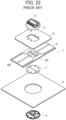
- JP 2021-61225 A discloses a connector 1 as illustrated in FIG. 22 .
- the connector 1 has the structure in which plural contacts 3 are retained on a first insulator 2, and a tab sheet 5, a sheet type conductive member 6, and a support sheet 7 are sandwiched and retained between the first insulator 2 and a second insulator 4.
- the connector 1 is attached to a garment 8 by fixing the tab sheet 5 to the garment 8.
- the sheet type conductive member 6 is provided at its central portion with a cut 6A used to attach the sheet type conductive member 6 to the connector 1, and one end portions of plural flexible conductors 6B are disposed near the cut 6A on a surface of the sheet type conductive member 6.
- each flexible conductor 6B makes contact with and is thereby connected to the corresponding contact 3, and the other end portion thereof is connected to a conductive wiring portion (not shown) disposed on the garment 8 by sewing or other means.
- electrodes of the garment 8 disposed at measurement sites are electrically connected to the contacts 3 of the connector 1 via the wiring portions and the flexible conductors 6B.
- the contact area would be small between the conductive threads constituting the flexible conductors 6B and the contacts 3 when the one end portions of the flexible conductors 6B are brought into contact with the contacts 3, and this may impair the reliability of electrical connection.
- the contact area would be small between the conductive threads constituting the flexible conductors 6B and the wiring portions of the garment 8, and this also may impair the reliability of electrical connection.
- EP 4 060 818 A1 and EP 4 000 436 A1 disclose further connectors and a connecting method.
- the present invention has been made to overcome the conventional problem as above and aims at providing a sheet type conductive member capable of improving the reliability of electrical connection with a contact of a connector and with a wiring portion of a mounting object such as a garment, despite having a flexible conductor formed of a conductive thread.
- the present invention also aims at providing a connector having the sheet type conductive member, a garment having the connector mounted thereon, and a connector mounting method for mounting the connector on a garment.
- a sheet type conductive member according to the present invention is defined in claim 1.
- a connector according to the present invention is defined in claim 6.
- a garment according to the present invention is defined in claim 13.
- a connector mounting method according to the present invention is defined in claim 15.
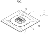
- FIGS. 1 and 2 show a connector 11 according to the embodiment.
- the connector 11 is mounted on a garment (mounting object) having a conductive wiring portion and is used as a connector for fitting a wearable device, for instance.
- the connector 11 includes a housing 12 made of an insulating material. A plurality of contacts 13 are retained in the housing 12, and a tab sheet 14 and a sheet type conductive member 15 being superposed on each other are retained by the housing 12.
- the contacts 13 are arranged in two rows parallel to each other and disposed to project perpendicularly to the sheet type conductive member 15.
- the tab sheet 14 and the sheet type conductive member 15 are defined as extending in an XY plane, the arrangement direction of the contacts 13 is referred to as "Y direction,” and the direction in which the contacts 13 project is referred to as "+Z direction.”
- the Z direction is a fitting direction in which the connector 11 is fitted to a counter connector.
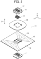
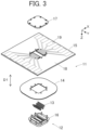
- FIGS. 2 and 3 are exploded perspective views of the connector 11.
- the connector 11 includes a first insulator 16 and a second insulator 17, and these first and second insulators 16 and 17 constitute the housing 12.
- the contacts 13 are separately and temporarily retained in the first insulator 16, and the second insulator 17 is assembled to the first insulator 16 in the Z direction which is a predetermined assembling direction D1, with the second insulator 17 and the first insulator 16 sandwiching the sheet type conductive member 15 and the tab sheet 14 therebetween.
- the predetermined assembling direction D1 is the same as the fitting direction in which the connector 11 is fitted to a counter connector.
- the sheet type conductive member 15 has a sheet body 18, and an embroidery pattern 19 embroidered on the sheet body 18 with embroidery threads.
- the embroidery pattern 19 is seen on both the front and back sides, facing the +Z and -Z directions, of the sheet type conductive member 15 as shown in FIGS. 2 and 3 .
- the first insulator 16 includes a base portion 16A of flat rectangular shape extending in an XY plane, a peripheral wall portion 16B projecting in the +Z direction from the circumferential edge portion of the base portion 16A, and a plurality of projection portions 16C projecting in the +Z direction from a surface of the base portion 16A and arranged in two rows parallel to each other within the region surrounded by the peripheral wall portion 16B.
- a gap 16D is formed between each adjacent pair of projection portions 16C.
- a recess portion 16E of rectangular shape that opens in the -Z direction is formed at the -Z direction-side surface of the base portion 16A, and the bottom of the recess portion 16E is provided with a plurality of through-holes 16F penetrating from the corresponding gaps 16D on the +Z direction side of the base portion 16A to the recess portion 16E.
- the through-holes 16F correspond to the contacts 13 and are arranged in two rows parallel to each other.
- the bottom of the recess portion 16E is provided with a plurality of retaining surfaces 16G adjacent to the through-holes 16F in the X direction.
- Each retaining surface 16G flatly extends in an XY plane between the corresponding through-hole 16F and an inner wall surface 16H, facing the X direction, of the recess portion 16E.
- the inner wall surfaces 16H, facing the X direction, of the recess portion 16E each constitute a first opposed surface extending in the Z direction that is the fitting direction.
- the -Z direction-side surface of the base portion 16A is provided with a plurality of fixing posts 16J projecting in the -Z direction.
- the second insulator 17 includes a base portion 17A of flat plate shape extending in an XY plane, a jut portion 17B of cuboid shape situated in the center of the base portion 17A and projecting in the +Z direction from the base portion 17A, and a plurality of columnar members 17C projecting in the +Z direction from the jut portion 17B.
- the jut portion 17B is inserted into the recess portion 16E of the first insulator 16 in assembling with the first insulator 16, and has a size slightly smaller than that of the recess portion 16E.
- the columnar members 17C correspond to the contacts 13 and are arranged in two rows parallel to each other.
- the base portion 17A is provided with a plurality of through-holes 17D situated around the jut portion 17B and penetrating through the base portion 17A in the Z direction. Those through-holes 17D correspond to the fixing posts 16J of the first insulator 16.
- Outer surfaces 17E, facing the X direction, of the jut portion 17B each constitute a second opposed surface extending in the Z direction that is the fitting direction.
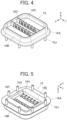
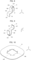
- FIGS. 8 and 9 show the structure of each of the contacts 13 arranged on the +X direction side, of the plurality of contacts 13 shown in FIGS. 2 and 3 .
- the contact 13 is constituted of a plug type contact formed of a band-shaped member made of a conductive material such as metal and includes a U-shaped portion 13A extending in the Z direction and bent in a U shape.
- the U-shaped portion 13A is composed of a pair of extension portions 13B and 13C extending along a YZ plane and facing each other in the X direction and a top portion 13D joining the +Z directional ends of the extension portions 13B and 13C to each other.
- the -Z directional end of the extension portion 13B is connected to a flat plate portion 13F extending in a YZ plane via a retained portion 13E extending in an XY plane.
- An outer surface of the U-shaped portion 13A forms a contacting portion S 1 that is to make contact with a contact of a counter connector, and a surface, on the -X direction side, of the flat plate portion 13F forms a connection portion S2 that is to make contact with a surface of the sheet type conductive member 15.
- the contacting portion S1 of the contact 13 projects in the +Z direction from the housing 12, while the connection portion S2 of the contact 13 is situated inside the housing 12.
- the contacts 13 arranged on the -X direction side have the same structure as that of the contact 13 shown in FIGS. 8 and 9 but are disposed in the opposite orientation in the X direction.
- the tab sheet 14 is used for attaching the connector 11 to a garment by fixing the tab sheet 14 to the garment by sewing or other means.
- the tab sheet 14 is made of an insulating material such as resin or cloth, and has a size larger than that of the base portion 16A of the first insulator 16 and that of the base portion 17A of the second insulator 17 in an XY plane.
- a substantially square opening portion 14A is formed in a central portion of the tab sheet 14.
- a portion of the tab sheet 14 around the opening portion 14A is, along with the sheet type conductive member 15, sandwiched between the base portion 16A of the first insulator 16 and the base portion 17A of the second insulator 17, and at this time, the jut portion 17B and the columnar members 17C of the second insulator 17 are inserted into the opening portion 14A.
- a plurality of through-holes 14B are formed around the opening portion 14A of the tab sheet 14. Those through-holes 14B correspond to the fixing posts 16J of the first insulator 16.
- the sheet type conductive member 15 is used for electrically connecting a plurality of wiring portions of a garment on which the connector 11 is mounted, to the contacts 13. As shown in FIG. 11 , the sheet type conductive member 15 includes: the sheet body 18 formed of insulating cloth or knitted fabric; and the embroidery pattern 19 embroidered on the sheet body 18 with embroidery threads.
- the sheet body 18 has a substantially square shape, extends in an XY plane, and has an H-shaped opening portion 18A in its central portion.
- the opening portion 18A is used when the sheet type conductive member 15 is attached to the connector 11, and the opening portion 18A is provided with a pair of protrusion pieces 18B that are formed of part of the sheet body 18 and protrude to face each other in the X direction inside the opening portion 18A.
- a plurality of through-holes 18C are formed around the opening portion 18A of the sheet body 18. Those through-holes 18C correspond to the fixing posts 16J of the first insulator 16.
- a conductive thread is used only for a part exposed on the surface of the sheet body 18 on the +Z direction side, while an insulating thread is used for a part exposed on the surface of the sheet body 18 on the -Z direction side.
- a flexible conductor 20 exposed on the surface of the sheet type conductive member 15 on the +Z direction side is thus formed.
- the flexible conductor 20 is formed by embroidery using a conductive thread.
- a so-called silver thread can be used for the conductive thread.
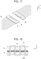
- the sheet type conductive member 15 includes a plurality of flexible conductors 20 disposed on the +X direction side of the opening portion 18A of the sheet body 18 and a plurality of flexible conductors 20 disposed on the -X direction side of the opening portion 18A.
- Each flexible conductor 20 includes a first end portion 20A disposed near a side, extending in the Y direction, of the square sheet body 18, a second end portion 20B disposed on the protrusion piece 18B of the sheet body 18, and a joint portion 20C joining the first end portion 20A and the second end portion 20B together.
- the second end portions 20B of the flexible conductors 20 disposed on the +X direction side of the opening portion 18A of the sheet body 18 and those disposed on the -X direction side of the opening portion 18A of the sheet body 18 are arranged in two rows on the opposite sides of the opening portion 18A to face each other across the opening portion 18A.
- the first end portions 20A are linearly arranged in the Y direction with first arrangement pitch P1
- the second end portions 20B are linearly arranged in the Y direction with second arrangement pitch P2 in parallel to the first end portions 20A.
- the second arrangement pitch P2 of the second end portions 20B corresponds to arrangement pitch of the contacts 13 in the Y direction.
- the first arrangement pitch P1 of the first end portions 20A is set larger than the second arrangement pitch P2 of the second end portions 20B.
- a width W1 in the Y direction, of the first end portion 20A of each flexible conductor 20 is set larger than a width W2, in the Y direction, of the second end portion 20B, and the joint portion 20C has the same width as that of the second end portion 20B.
- the first end portions 20A are arranged in the Y direction with the first arrangement pitch P 1 larger than the arrangement pitch of the contacts 13, and thus, the first end portions 20A are configured such that a larger distance can be ensured between every two first end portions 20A adjacent in the Y direction even though the first end portions 20A have the width W1 larger than the width W2 of the second end portions 20B.
- each flexible conductor 20 has a length L1 in the X direction larger than the width W1 in the Y direction.
- the first end portion 20A, the second end portion 20B, and the joint portion 20C constituting the flexible conductor 20 are formed of conductive threads embroidered on the sheet body 18, while the density of embroidery of conductive threads, i.e., the degree of packing of exposed portions of conductive threads is not uniform but varies. More specifically, the density of embroidery of conductive threads in the first end portion 20A and the second end portion 20B is set higher than that in the joint portion 20C.
- the embroidery is formed in the first end portion 20A and the second end portion 20B to have exposed portions of conductive threads being more tightly packed than in the joint portion 20C.
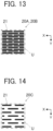
- the density of embroidery of conductive threads or the degree of packing of exposed portions of conductive threads has a relation to not only the number of the conductive threads but also the thickness of the conductive threads used in regions of equal area. To deal with it, an exposure area of conductive threads per unit area is used as an index representing the density of embroidery of conductive threads or the degree of packing of exposed portions of conductive threads.
- a region U having a unit area in the first end portion 20A and the second end portion 20B is focused as shown in FIG. 13 , and the total occupied area of conductive threads 21 exposed toward the +Z direction within the region U is defined as an exposure area A1.
- a region U having the unit area in the joint portion 20C is focused as shown in FIG. 14 , and the total occupied area of conductive threads 21 exposed toward the +Z direction within the region U is defined as an exposure area A2.
- the exposure area A1 of the conductive threads 21 per unit area in the first end portion 20A and the second end portion 20B is set larger than the exposure area A2 of the conductive threads 21 per unit area in the joint portion 20C.
- the number of the conductive threads 21 used in the first end portion 20A and the second end portion 20B per unit area is set larger than the number of the conductive threads 21 used in the joint portion 20C per unit area.
- the conductive thread 21 used in the first end portion 20A and the second end portion 20B is set thicker than the conductive thread 21 used in the joint portion 20C, even if the number of the conductive threads 21 used in the first end portion 20A and the second end portion 20B per unit area is the same as the number of the conductive threads 21 used in the joint portion 20C per unit area, the exposure area A1 of the conductive threads 21 per unit area in the first end portion 20A and the second end portion 20B can be larger than the exposure area A2 of the conductive threads 21 per unit area in the joint portion 20C.
- the first end portions 20A are linearly arranged in the Y direction with the first arrangement pitch P1
- the second end portions 20B are linearly arranged in the Y direction with the second arrangement pitch P2 in parallel to the first end portions 20A.
- the first end portion 20A of each flexible conductor 20 has the width W1 in the Y direction larger than the width W2 of the second end portion 20B in the Y direction
- the joint portion 20C has the same width as that of the second end portion 20B
- the first end portion 20A has the length L1 in the X direction larger than the width W1 in the Y direction.
- the density of embroidery of conductive threads in the first end portion 20A and the second end portion 20B is set higher than that in the joint portion 20C, and the exposure area A1 of the conductive threads 21 per unit area in the first end portion 20A and the second end portion 20B is set larger than the exposure area A2 of the conductive threads 21 per unit area in the joint portion 20C.
- a silver thread used as the conductive thread is formed by wrapping a silver foil around a thread or by cutting a silver foil into thin strips and twisting the strips into a weaving yarn, for instance.
- a silver thread is expensive, an increase in manufacturing cost of the sheet type conductive member 15 can be suppressed because the silver thread is not embroidered with high density over the entire flexible conductor 20 but the exposure area A1 of the conductive threads 21 per unit area in the first end portion 20A and the second end portion 20B is set larger than the exposure area A2 of the conductive threads 21 per unit area in the joint portion 20C.
- the respective contacts 13 are pushed into the first insulator 16 from the -Z direction toward the +Z direction, whereby the contacts 13 are temporarily retained in the first insulator 16.
- the U-shaped portion 13A of each contact 13 is passed through the corresponding through-hole 16F from the recess portion 16E on the -Z direction side of the first insulator 16 and inserted into the corresponding gap 16D formed between adjacent projection portions 16C, so that the contacting portion S1 formed of the outer surface of the U-shaped portion 13A is exposed on the +Z direction side of the first insulator 16.
- each contact 13 is situated inside the recess portion 16E of the first insulator 16, and the flat plate portion 13F makes contact with the inner wall surface 16H of the recess portion 16E of the first insulator 16.
- the fixing posts 16J of the first insulator 16 are sequentially passed through the through-holes 14B of the tab sheet 14 and the through-holes 18C of the sheet type conductive member 15 such that the tab sheet 14 and the sheet type conductive member 15 lie on the -Z direction side of the first insulator 16.
- the fixing posts 16J of the first insulator 16 are further passed through the through-holes 17D of the second insulator 17, and the second insulator 17 is moved in the +Z direction toward the first insulator 16 to start the assembly into the first insulator 16.
- the columnar members 17C of the second insulator 17 are each inserted into the inside of the U-shaped portion 13A of the corresponding contact 13 from the -Z direction.
- the jut portion 17B of the second insulator 17 is sequentially passed through the opening portion 18A of the sheet type conductive member 15 and the opening portion 14A of the tab sheet 14 from the -Z direction and then inserted into the recess portion 16E of the first insulator 16.
- the pair of protrusion pieces 18B situated inside the opening portion 18A of the sheet type conductive member 15 are pushed while being bent toward the +Z direction by the jut portion 17B of the second insulator 17 and each enter between the flat plate portion 13F of the contact 13 in contact with the inner wall surface 16H of the recess portion 16E of the first insulator 16 and the outer surface 17E of the jut portion 17B of the second insulator 17.
- each contact 13 is sandwiched between the +Z direction-side surface of the jut portion 17B of the second insulator 17 and the retaining surface 16G inside the recess portion 16E of the first insulator 16.
- the contacts 13 are retained by the first insulator 16 and the second insulator 17 in this manner.
- each protrusion piece 18B of the sheet body 18 of the sheet type conductive member 15 are pushed and bent toward the +Z direction by the jut portion 17B of the second insulator 17, and in this state, each protrusion piece 18B is sandwiched between the inner wall surface 16H, which constitutes the first opposed surface, of the recess portion 16E of the first insulator 16 and the outer surface 17E, which constitutes the second opposed surface, of the jut portion 17B of the second insulator 17, so that the second end portion 20B of each flexible conductor 20 exposed on the surface of the protrusion piece 18B makes contact at a predetermined contact pressure with the connection portion S2 of the flat plate portion 13F of the corresponding contact 13 being in contact with the inner wall surface 16H of the recess portion 16E of the first insulator 16.
- the contacts 13 are electrically connected to the second end portions 20B of the corresponding flexible conductors 20 of the sheet type conductive member 15.
- the density of embroidery of conductive threads in the second end portion 20B of the flexible conductor 20 is higher than that in the joint portion 20C, and the exposure area A1 of the conductive threads 21 per unit area in the second end portion 20B is larger than the exposure area A2 of the conductive threads 21 per unit area in the joint portion 20C. Accordingly, the connection portion S2 of the flat plate portion 13F of the contact 13 and the second end portion 20B of the flexible conductor 20 can have a large substantial contact area therebetween, thus making it possible to electrically connect the second end portion 20B to the contact 13 with high reliability.
- the fixing posts 16J of the first insulator 16 are passed through the corresponding through-holes 17D of the second insulator 17 and project on the -Z direction side of the second insulator 17.
- the connector 11 shown in FIG. 1 is thus assembled.
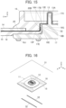
- Two slits 32 are formed in the garment 31 at a position where the connector 11 is to be attached, as shown in FIG. 16 .
- the two slits 32 extend in the Y direction in parallel to each other with a distance therebetween in the X direction and penetrate the garment 31 from the front side to the back side.
- the two slits 32 have a length in the Y direction slightly larger than the Y directional length of the sheet type conductive member 15 of the connector 11 and are spaced apart from each other in the X direction with a distance slightly larger than the X directional length of the housing 12 of the connector 11.
- the back side, facing the -Z direction, of the garment 31 is provided with a plurality of conductive wiring portions 33 separately extending in the +X and -X directions perpendicular to the two slits 32.
- One ends of those wiring portions 33 are arranged in the Y direction with the same arrangement pitch as that of the first end portions 20A of the sheet type conductive member 15 in the vicinity of the corresponding slit 32, and have the substantially same width in the Y direction as that of the first end portions 20A.
- the wiring portions 33 are made of, for example, a conductive thread sewn into the garment 31, and at least their surfaces facing the -Z direction have conductivity. The other ends of the wiring portions 33 each extend along the back side of the garment 31 up to an electrode (not shown) attached to the garment 31.
- the +X directional portion and the -X directional portion of the sheet type conductive member 15 drawn to the back side, facing the -Z direction, of the garment 31 through the two slits 32 of the garment 31 are disposed to be superposed on the one ends of the wiring portions 33.
- each first end portion 20A of the sheet type conductive member 15 is superposed on the -Z direction side of the corresponding wiring portion 33 of the garment 31 as shown in FIG. 18 .
- the garment 31 and the sheet type conductive member 15 are sewed together with a sewing thread 41, whereby the first end portions 20A of the sheet type conductive member 15 can be electrically connected to the wiring portions 33 of the garment 31 on a one-to-one basis.
- the width W 1, in the Y direction, of the first end portion 20A of the sheet type conductive member 15 is set larger than the width W2, in the Y direction, of the second end portion 20B as shown in FIG. 12 , and the wiring portion 33 of the garment 31 has substantially the same width in the Y direction as that of the first end portion 20A.
- the density of embroidery of conductive threads in the first end portion 20A of the flexible conductor 20 is higher than that in the joint portion 20C, and the exposure area A1 of the conductive threads 21 per unit area in the first end portion 20A is larger than the exposure area A2 of the conductive threads 21 per unit area in the joint portion 20C.
- the wiring portion 33 of the garment 31 and the first end portion 20A of the flexible conductor 20 can have a large substantial contact area therebetween, thus making it possible to electrically connect the first end portion 20A to the wiring portion 33 of the garment 31 with high reliability.
- the width W1 in the Y direction, of the first end portion 20A of the sheet type conductive member 15 is larger than the width W2, in the Y direction, of the second end portion 20B, and the wiring portion 33 of the garment 31 has substantially the same width in the Y direction as that of the first end portion 20A, even when a little misalignment occurs in the Y direction between the first end portions 20A of the sheet type conductive member 15 and the wiring portions 33 of the garment 31 due to manufacturing tolerances of the sheet type conductive member 15 and the wiring portions 33 of the garment 31 or other reasons, the contact area can still be ensured between the first end portions 20A and the wiring portions 33, thus leading to reliable electrical connection therebetween.
- the tab sheet 14 of the connector 11 is also sewed on the garment 31 with the sewing thread 41, whereby the connector 11 can be fixed to the garment 31.
- the sewing thread 41 used for sewing may be an insulating thread or a conductive thread.
- the plurality of first end portions 20A of the sheet type conductive member 15 can be sewed on the plurality of wiring portions 33 of the garment 31 with the sewing thread 41 all at once.
- a portion of the sheet type conductive member 15 situated on the +X direction side of the housing 12 and a portion thereof situated on the -X direction side of the housing 12 are separately passed through the corresponding slits 32 of the garment 31 and thereby drawn from the front side toward the back side of the garment 31; however, the invention is not limited thereto.
- the connector 11 shown in FIG. 16 can be simply disposed on the surface, facing the +Z direction, of the garment 31 and mounted on the garment 31 without having a portion of the sheet type conductive member 15 drawn to the back side of the garment 31.
- the first end portion 20A is sewed through the sheet body 18 and the garment 31 to the wiring portion 33 with the sewing thread 42 having conductivity, whereby the first end portion 20A and the wiring portion 33 can be electrically connected via the sewing thread 42.
- the density of embroidery of conductive threads in the first end portion 20A of the flexible conductor 20 is higher than that in the joint portion 20C, and the exposure area A1 of the conductive threads 21 per unit area in the first end portion 20A is larger than the exposure area A2 of the conductive threads 21 per unit area in the joint portion 20C, thus leading to a large contact area between the first end portion 20A and the sewing thread 42 having conductivity. This improves the reliability of electrical connection between the first end portion 20A and the wiring portion 33.
- each first end portion 20A has to be sewed to the corresponding wiring portion 33 with an independent sewing thread 42 on a one-to-one basis in order to prevent a short between the plural first end portions 20.
- FIG. 20 shows a counter connector 51 to be fitted to the connector 11 according to the embodiment.
- the counter connector 51 includes a housing 52 made of an insulating material, and a plurality of contacts 53 are retained in the housing 52.
- the contacts 53 correspond to the contacts 13 of the connector 11 and are arranged in two rows parallel to each other with the same arrangement pitch as that of the contacts 13. Each contact 53 faces the -Z direction and is a receptacle type contact corresponding to the plug type contact 13 of the connector 11.
- a peripherally rounding groove 52A facing the -Z direction is formed in the housing 52 to surround the periphery of the contacts 53.
- the peripherally rounding groove 52A corresponds to the peripheral wall portion 16B of the first insulator 16 of the connector 11.
- the counter connector 51 includes a first insulator 54 and a second insulator 55 as shown in FIG. 21 , and these first and second insulators 54 and 55 constitute the housing 52.
- the contacts 53 are retained in the second insulator 55, and the peripherally rounding groove 52A is also formed in the second insulator 55.
- the counter connector 51 further includes a circuit board 56, and a plurality of fixing screws 57 used to fix the circuit board 56 to the first insulator 54.
- the contacts 53 retained in the second insulator 55 are connected to a plurality of connection pads 56A of the circuit board 56 by soldering or another method, and the circuit board 56 is fixed to the first insulator 54 by means of the fixing screws 57.
- the counter connector 51 is assembled.
- Components such as a wireless transmitting circuit (not shown) connected to the contacts 53 are mounted on a surface, facing the +Z direction, of the circuit board 56 opposite from the housing 52.
- the plug type contacts 13 of the connector 11 are inserted into the receptacle type contacts 53 of the counter connector 51 and electrically connected thereto.
- the peripheral wall portion 16B of the first insulator 16 of the connector 11 is inserted into the peripherally rounding groove 52A of the housing 52 of the counter connector 51, whereby the counter connector 51 is retained with respect to the connector 11.
- user's biological data such as the heart rate and the body temperature as obtained using electrodes attached to the garment 31 can be input to the wireless transmitting circuit mounted on the circuit board 56 through the wiring portions 33 of the garment 31, the flexible conductors 20 of the sheet type conductive member 15 and the contacts 13 of the connector 11, and the contacts 53 of the counter connector 51, and wirelessly transmitted from the wireless transmitting circuit to a tablet terminal, a stationary measurement device, or the like.
- the contacts 13 are arranged in two rows parallel to each other, the invention is not limited thereto, and the contacts 13 may be arranged in one row. Further, this invention does not necessarily require the plurality of contacts 13, and it suffices if at least one contact 13 is provided.
- the flexible conductor 20 of the sheet type conductive member 15 is exposed on the surface of the sheet body 18 on the +Z direction side, the flat plate portion 13F of the contact 13 makes contact with the inner wall surface 16H of the recess portion 16E of the first insulator 16, the protrusion piece 18B of the sheet type conductive member 15 is sandwiched between the flat plate portion 13F of the contact 13 and the outer surface 17E of the jut portion 17B of the second insulator 17, and the second end portion 20B of the flexible conductor 20 exposed on the surface of the protrusion piece 18B is electrically connected to the contact 13; however, the invention is not limited thereto.
- the flexible conductor 20 of the sheet type conductive member 15 may be exposed on the surface of the sheet body 18 on the -Z direction side.
- the flat plate portion 13F of the contact 13 is disposed to make contact with the outer surface 17E of the jut portion 17B of the second insulator 17, the protrusion piece 18B of the sheet type conductive member 15 is sandwiched between the flat plate portion 13F of the contact 13 and the inner wall surface 16H of the recess portion 16E of the first insulator 16, and the second end portion 20B of the flexible conductor 20 exposed on the surface of the protrusion piece 18B is electrically connected to the flat plate portion 13F of the contact 13.
- both portions exposed on the surfaces of the sheet body 18 on the +Z direction side and the -Z direction side may be formed by embroidery using conductive threads, so that the flexible conductors 20 can be exposed on both surfaces of the sheet body 18.
- the flexible conductor 20 of the sheet type conductive member 15 is formed of a conductive thread embroidered on the sheet body 18 in the embodiment above, the invention is not limited thereto, and the flexible conductor 20 may be formed by weaving a conductive thread into the sheet body 18 made of insulating cloth or knitted fabric.
- the tab sheet 14 is disposed between the housing 12 and the sheet type conductive member 15, the tab sheet 14 may be omitted when it is not particularly necessary to reinforce the portion receiving the connector 11 when the connector 11 is mounted on the garment 31.
- the connector 11 is mounted on the garment 31 that is the mounting object in the embodiment above, the mounting object is not limited to the garment 31, and the connector 11 may be mounted on, for example, a bag that the user carries or wears, or a sheet, a bed or a bedding piece on or in which the user lies.
Landscapes
- Engineering & Computer Science (AREA)
- Microelectronics & Electronic Packaging (AREA)
- Textile Engineering (AREA)
- Manufacturing & Machinery (AREA)
- Coupling Device And Connection With Printed Circuit (AREA)
- Details Of Garments (AREA)
Claims (16)
- Flachmaterialartiges leitfähiges Element (15), das dazu konfiguriert ist, an einem Verbinder (11) angebracht zu werden, der an einem Montageobjekt (31) montiert ist, und dafür eingerichtet ist, einen Verdrahtungsabschnitt (33) des Montageobjekts elektrisch mit einem Kontakt (13) des Verbinders zu verbinden, wobei das flachmaterialartige leitfähige Element umfasst:einen Flachmaterialkörper (18), der eine isolierende Eigenschaft aufweist; undeinen flexiblen Leiter (20), der aus einem leitfähigen Faden gebildet ist, der so auf den Flachmaterialkörper gestickt oder darin eingewebt ist, dass er an einer Oberfläche des Flachmaterialkörpers frei liegt, wobei sich der flexible Leiter entlang der Oberfläche des Flachmaterialkörpers erstreckt,wobei der flexible Leiter einen ersten Endabschnitt (20A), der elektrisch mit dem Verdrahtungsabschnitt verbunden ist, einen zweiten Endabschnitt (20B), der elektrisch mit dem Kontakt verbunden ist, und einen Verbindungsabschnitt (20C), der den ersten Endabschnitt und den zweiten Endabschnitt miteinander verbindet, aufweist, dadurch gekennzeichnet, dasseine Dichte der Stickerei aus leitfähigem Faden, die durch einen Packungsgrad von frei liegenden Abschnitten leitfähigen Fadens angegeben ist, nicht einheitlich ist, sondern variiert, und eine Exponierungsfläche von leitfähigem Faden pro Flächeneinheit als ein Index verwendet wird, der die Dichte der Stickerei aus leitfähigem Faden oder den Packungsgrad von frei liegenden Abschnitten leitfähigen Fadens darstellt, unddie Exponierungsfläche des leitfähigen Fadens pro Flächeneinheit in dem ersten Endabschnitt und in dem zweiten Endabschnitt größer ist als die Exponierungsfläche des leitfähigen Fadens pro Flächeneinheit in dem Verbindungsabschnitt.
- Flachmaterialartiges leitfähiges Element nach Anspruch 1, umfassend mehrere flexible Leiter (20),wobei die ersten Endabschnitte (20A) der mehreren flexiblen Leiter linear mit einem ersten Anordnungsabstand (P1) angeordnet sind,die zweiten Endabschnitte (20B) der mehreren flexiblen Leiter linear mit einem zweiten Anordnungsabstand (P2) parallel zu den ersten Endabschnitten der mehreren flexiblen Leiter angeordnet sind undder erste Anordnungsabstand größer als der zweite Anordnungsabstand ist.
- Flachmaterialartiges leitfähiges Element nach Anspruch 2,wobei der Flachmaterialkörper (18) einen Öffnungsabschnitt (18A) aufweist, der zur Anbringung an dem Verbinder verwendet wird, unddie zweiten Endabschnitte (20B) der mehreren flexiblen Leiter in zwei Reihen auf gegenüberliegenden Seiten des Öffnungsabschnitts so angeordnet sind, dass sie einander über den Öffnungsabschnitt hinweg gegenüber liegen.
- Flachmaterialartiges leitfähiges Element nach Anspruch 3,
wobei der Flachmaterialkörper (18) ein Vorsprungstück (18B) aufweist, das in den Öffnungsabschnitt (18A) hineinragt, und der zweite Endabschnitt (20B) des flexiblen Leiters an dem Vorsprungstück angeordnet ist. - Flachmaterialartiges leitfähiges Element nach einem der Ansprüche 1-4,
wobei der erste Endabschnitt (20A) eine größere Breite (W1) als eine Breite (W2) des zweiten Endabschnitts (20B) hat und der Verbindungsabschnitt (20C) eine gleiche Breite wie die Breite des zweiten Endabschnitts hat. - Verbinder (11), der dazu konfiguriert ist, an einem Montageobjekt (31) montiert zu werden, wobei der Verbinder umfasst:ein flachmaterialartiges leitfähiges Element (15) nach einem der Ansprüche 1-5;einen Kontakt (13), der elektrisch mit dem zweiten Endabschnitt (20B) des flachmaterialartigen leitfähigen Elements verbunden ist; undein Gehäuse (12), das eine isolierende Eigenschaft aufweist und dafür eingerichtet ist, das flachmaterialartige leitfähige Element und den Kontakt zurückzuhalten,wobei der Verbinder dafür eingerichtet ist, mit einem Gegenverbinder in einer Steckrichtung zusammengesteckt zu werden.
- Verbinder nach Anspruch 6,wobei das Gehäuse (12) einen ersten Isolator (16) und einen zweiten Isolator (17) aufweist, die in einer zuvor festgelegten Montagerichtung (D1) zusammengebaut sind, während das flachmaterialartige leitfähige Element dazwischen sandwichartig angeordnet ist, undder Kontakt (13) einen Kontaktierungsabschnitt (S1) und einen Verbindungsabschnitt (S2) aufweist, wobei der Kontaktierungsabschnitt in der Steckrichtung von dem ersten Isolator vorsteht und dafür ausgelegt ist, mit einem Kontakt (53) des Gegenverbinders einen Kontakt herzustellen, und der Verbindungsabschnitt sich im Inneren des Gehäuses befindet und mit dem zweiten Endabschnitt (20B) des flexiblen Leiters des flachmaterialartigen leitfähigen Elements verbunden ist.
- Verbinder nach Anspruch 7,wobei der erste Isolator (16) eine erste gegenüberliegende Fläche (16H) aufweist, die sich in der Steckrichtung erstreckt,der zweite Isolator (17) eine zweite gegenüberliegende Fläche (17E) aufweist, die sich in der Steckrichtung erstreckt und der ersten gegenüberliegenden Fläche zugewandt ist, undder zweite Endabschnitt (20B) des flexiblen Leiters des flachmaterialartigen leitfähigen Elements und der Verbindungsabschnitt (S2) des Kontakts zwischen der ersten gegenüberliegenden Fläche und der zweiten gegenüberliegenden Fläche sandwichartig aufgenommen sind und in diesem Zustand elektrisch miteinander verbunden sind.
- Verbinder nach Anspruch 7 oder 8,
wobei der Kontakt (13) einen zurückgehaltenen Abschnitt (13E) aufweist, der sich zwischen dem Kontaktierungsabschnitt (S1) und dem Verbindungsabschnitt (S2) befindet und durch das Gehäuse (12) zurückgehalten wird, indem er zwischen dem ersten Isolator und dem zweiten Isolator sandwichartig aufgenommen ist. - Verbinder nach Anspruch 9,
wobei der zurückgehaltene Abschnitt (13E) zwischen dem ersten Isolator und dem zweiten Isolator in der zuvor festgelegten Montagerichtung (D1) sandwichartig aufgenommen ist. - Verbinder nach einem der Ansprüche 7-10,
wobei die zuvor festgelegte Montagerichtung (D1) die gleiche ist wie die Steckrichtung. - Verbinder nach einem der Ansprüche 7-11, umfassend eine Aufnähplatte (14), die eine isolierende Eigenschaft aufweist und zwischen dem ersten Isolator (16) und dem flachmaterialartigen leitfähigen Element (15) sandwichartig aufgenommen ist,
wobei die Aufnähplatte dazu konfiguriert ist, an das Montageobjekt genäht und dadurch an dem Montageobjekt (31) befestigt zu werden. - Kleidungsstück (31), an dem der Verbinder (11) nach einem der Ansprüche 6-12 montiert ist.
- Kleidungsstück nach Anspruch 13,
wobei das Kleidungsstück mit einem Schlitz (32) versehen ist, durch den ein Teil des flachmaterialartigen leitfähigen Elements (15) hindurchgeführt ist. - Verbindermontageverfahren zum Montieren des Verbinders (11) nach einem der Ansprüche 6-12 an einem Kleidungsstück (31), wobei das Verfahren umfasst:Positionieren des flachmaterialartigen leitfähigen Elements (15) in Bezug auf das Kleidungsstück so, dass der erste Endabschnitt (20A) des flachmaterialartigen leitfähigen Elements an dem Verdrahtungsabschnitt (33) des Kleidungsstücks aufliegt; undNähen des ersten Endabschnitts an den Verdrahtungsabschnitt, um dadurch das flachmaterialartige leitfähige Element an dem Kleidungsstück anzubringen und den ersten Endabschnitt elektrisch mit dem Verdrahtungsabschnitt zu verbinden.
- Verbindermontageverfahren nach Anspruch 15,wobei der Verdrahtungsabschnitt (33) an einer Rückseite des Kleidungsstücks (31) angeordnet wird,der zweite Endabschnitt (20B) des flachmaterialartigen leitfähigen Elements (15) an einer Vorderseite des Kleidungsstücks angeordnet wird,der erste Endabschnitt (20A) des flachmaterialartigen leitfähigen Elements durch einen in dem Kleidungsstück ausgebildeten Schlitz hindurchgeführt wird, um auf dem Verdrahtungsabschnitt (33) auf der Rückseite des Kleidungsstücks angeordnet zu werden, undder erste Endabschnitt an den Verdrahtungsabschnitt genäht wird.
Applications Claiming Priority (1)
| Application Number | Priority Date | Filing Date | Title |
|---|---|---|---|
| JP2022115445A JP2024013391A (ja) | 2022-07-20 | 2022-07-20 | シート状導電部材、コネクタ、衣服およびコネクタ実装方法 |
Publications (2)
| Publication Number | Publication Date |
|---|---|
| EP4311033A1 EP4311033A1 (de) | 2024-01-24 |
| EP4311033B1 true EP4311033B1 (de) | 2024-10-16 |
Family
ID=86692732
Family Applications (1)
| Application Number | Title | Priority Date | Filing Date |
|---|---|---|---|
| EP23177448.0A Active EP4311033B1 (de) | 2022-07-20 | 2023-06-06 | Leitfähiges bahnenelement, verbinder, kleidungsstück und verbindermontageverfahren |
Country Status (4)
| Country | Link |
|---|---|
| US (1) | US12506286B2 (de) |
| EP (1) | EP4311033B1 (de) |
| JP (1) | JP2024013391A (de) |
| CN (1) | CN117438136A (de) |
Families Citing this family (1)
| Publication number | Priority date | Publication date | Assignee | Title |
|---|---|---|---|---|
| JP2024013427A (ja) * | 2022-07-20 | 2024-02-01 | 日本航空電子工業株式会社 | シート状導電部材の製造方法、シート状導電部材、コネクタ、衣服およびコネクタ実装方法 |
Family Cites Families (9)
| Publication number | Priority date | Publication date | Assignee | Title |
|---|---|---|---|---|
| US8505474B2 (en) * | 2007-07-31 | 2013-08-13 | Snu R&Db Foundation | Electrically conductive metal composite embroidery yarn and embroidered circuit using thereof |
| KR100966842B1 (ko) * | 2008-02-26 | 2010-06-29 | 한국생산기술연구원 | 자수 기술을 이용한 디지털 가먼트 및 그 제조 방법 |
| US12476181B2 (en) * | 2018-05-03 | 2025-11-18 | University Of Louisville Research Foundation, Inc. | Electrical contact array for harvesting power from a power circuit |
| JP7093259B2 (ja) * | 2018-07-18 | 2022-06-29 | 日本航空電子工業株式会社 | 衣服用コネクタ |
| US20200325603A1 (en) * | 2019-04-10 | 2020-10-15 | Propel, LLC | Knitted textiles with conductive traces of a hybrid yarn and methods of knitting the same |
| JP7348060B2 (ja) * | 2019-10-03 | 2023-09-20 | 日本航空電子工業株式会社 | コネクタおよび接続方法 |
| US11258189B2 (en) | 2019-10-03 | 2022-02-22 | Japan Aviation Electronics Industry, Limited | Connector and connecting method |
| JP7522642B2 (ja) * | 2020-11-18 | 2024-07-25 | 日本航空電子工業株式会社 | コネクタ |
| JP7558095B2 (ja) * | 2021-03-19 | 2024-09-30 | 日本航空電子工業株式会社 | コネクタおよび接続方法 |
-
2022
- 2022-07-20 JP JP2022115445A patent/JP2024013391A/ja active Pending
-
2023
- 2023-06-02 CN CN202310652103.5A patent/CN117438136A/zh active Pending
- 2023-06-06 EP EP23177448.0A patent/EP4311033B1/de active Active
- 2023-06-20 US US18/338,202 patent/US12506286B2/en active Active
Also Published As
| Publication number | Publication date |
|---|---|
| US20240030631A1 (en) | 2024-01-25 |
| EP4311033A1 (de) | 2024-01-24 |
| US12506286B2 (en) | 2025-12-23 |
| JP2024013391A (ja) | 2024-02-01 |
| CN117438136A (zh) | 2024-01-23 |
Similar Documents
| Publication | Publication Date | Title |
|---|---|---|
| EP4311030B1 (de) | Leitfähiges bahnenelement, verbinder, kleidungsstück und verbindermontageverfahren | |
| US20220302617A1 (en) | Connector and connecting method | |
| JP7313991B2 (ja) | コネクタ | |
| US12525738B2 (en) | Method of manufacturing sheet type conductive member, sheet type conductive member, connector, garment, and connector mounting method | |
| EP4346017B1 (de) | Verbinder | |
| EP4311033B1 (de) | Leitfähiges bahnenelement, verbinder, kleidungsstück und verbindermontageverfahren | |
| EP4311031B1 (de) | Kleidungsstück, an dem ein verbinder angebracht ist, und verfahren zum zusammenbau eines solchen kleidungsstücks | |
| US12506313B2 (en) | Sheet type conductive member and connector | |
| US20230223717A1 (en) | Connector | |
| US20240388027A1 (en) | Connector, connector assembly, connecting structure, and connecting method | |
| US20240222890A1 (en) | Connector and connector assembly | |
| US20240250461A1 (en) | Connector | |
| EP4611180A1 (de) | Verbinder | |
| US20240347994A1 (en) | Connecting method, connecting member, wiring member, and garment | |
| US20240088590A1 (en) | Connector |
Legal Events
| Date | Code | Title | Description |
|---|---|---|---|
| PUAI | Public reference made under article 153(3) epc to a published international application that has entered the european phase |
Free format text: ORIGINAL CODE: 0009012 |
|
| STAA | Information on the status of an ep patent application or granted ep patent |
Free format text: STATUS: REQUEST FOR EXAMINATION WAS MADE |
|
| 17P | Request for examination filed |
Effective date: 20230606 |
|
| AK | Designated contracting states |
Kind code of ref document: A1 Designated state(s): AL AT BE BG CH CY CZ DE DK EE ES FI FR GB GR HR HU IE IS IT LI LT LU LV MC ME MK MT NL NO PL PT RO RS SE SI SK SM TR |
|
| RBV | Designated contracting states (corrected) |
Designated state(s): AL AT BE BG CH CY CZ DE DK EE ES FI FR GB GR HR HU IE IS IT LI LT LU LV MC ME MK MT NL NO PL PT RO RS SE SI SK SM TR |
|
| GRAP | Despatch of communication of intention to grant a patent |
Free format text: ORIGINAL CODE: EPIDOSNIGR1 |
|
| STAA | Information on the status of an ep patent application or granted ep patent |
Free format text: STATUS: GRANT OF PATENT IS INTENDED |
|
| RIC1 | Information provided on ipc code assigned before grant |
Ipc: H01R 12/65 20110101ALN20240607BHEP Ipc: H01R 12/77 20110101ALI20240607BHEP Ipc: H01R 12/70 20110101ALI20240607BHEP Ipc: H01R 12/59 20110101AFI20240607BHEP |
|
| INTG | Intention to grant announced |
Effective date: 20240702 |
|
| GRAS | Grant fee paid |
Free format text: ORIGINAL CODE: EPIDOSNIGR3 |
|
| GRAA | (expected) grant |
Free format text: ORIGINAL CODE: 0009210 |
|
| STAA | Information on the status of an ep patent application or granted ep patent |
Free format text: STATUS: THE PATENT HAS BEEN GRANTED |
|
| AK | Designated contracting states |
Kind code of ref document: B1 Designated state(s): AL AT BE BG CH CY CZ DE DK EE ES FI FR GB GR HR HU IE IS IT LI LT LU LV MC ME MK MT NL NO PL PT RO RS SE SI SK SM TR |
|
| RAP3 | Party data changed (applicant data changed or rights of an application transferred) |
Owner name: JAPAN AVIATION ELECTRONICS INDUSTRY, LIMITED |
|
| REG | Reference to a national code |
Ref country code: GB Ref legal event code: FG4D |
|
| REG | Reference to a national code |
Ref country code: CH Ref legal event code: EP |
|
| REG | Reference to a national code |
Ref country code: IE Ref legal event code: FG4D |
|
| REG | Reference to a national code |
Ref country code: DE Ref legal event code: R096 Ref document number: 602023000749 Country of ref document: DE |
|
| REG | Reference to a national code |
Ref country code: LT Ref legal event code: MG9D |
|
| REG | Reference to a national code |
Ref country code: NL Ref legal event code: MP Effective date: 20241016 |
|
| REG | Reference to a national code |
Ref country code: AT Ref legal event code: MK05 Ref document number: 1733721 Country of ref document: AT Kind code of ref document: T Effective date: 20241016 |
|
| PG25 | Lapsed in a contracting state [announced via postgrant information from national office to epo] |
Ref country code: NL Free format text: LAPSE BECAUSE OF FAILURE TO SUBMIT A TRANSLATION OF THE DESCRIPTION OR TO PAY THE FEE WITHIN THE PRESCRIBED TIME-LIMIT Effective date: 20241016 |
|
| PG25 | Lapsed in a contracting state [announced via postgrant information from national office to epo] |
Ref country code: NL Free format text: LAPSE BECAUSE OF FAILURE TO SUBMIT A TRANSLATION OF THE DESCRIPTION OR TO PAY THE FEE WITHIN THE PRESCRIBED TIME-LIMIT Effective date: 20241016 |
|
| PG25 | Lapsed in a contracting state [announced via postgrant information from national office to epo] |
Ref country code: HR Free format text: LAPSE BECAUSE OF FAILURE TO SUBMIT A TRANSLATION OF THE DESCRIPTION OR TO PAY THE FEE WITHIN THE PRESCRIBED TIME-LIMIT Effective date: 20241016 Ref country code: IS Free format text: LAPSE BECAUSE OF FAILURE TO SUBMIT A TRANSLATION OF THE DESCRIPTION OR TO PAY THE FEE WITHIN THE PRESCRIBED TIME-LIMIT Effective date: 20250216 Ref country code: PT Free format text: LAPSE BECAUSE OF FAILURE TO SUBMIT A TRANSLATION OF THE DESCRIPTION OR TO PAY THE FEE WITHIN THE PRESCRIBED TIME-LIMIT Effective date: 20250217 |
|
| PG25 | Lapsed in a contracting state [announced via postgrant information from national office to epo] |
Ref country code: FI Free format text: LAPSE BECAUSE OF FAILURE TO SUBMIT A TRANSLATION OF THE DESCRIPTION OR TO PAY THE FEE WITHIN THE PRESCRIBED TIME-LIMIT Effective date: 20241016 |
|
| PG25 | Lapsed in a contracting state [announced via postgrant information from national office to epo] |
Ref country code: BG Free format text: LAPSE BECAUSE OF FAILURE TO SUBMIT A TRANSLATION OF THE DESCRIPTION OR TO PAY THE FEE WITHIN THE PRESCRIBED TIME-LIMIT Effective date: 20241016 |
|
| PG25 | Lapsed in a contracting state [announced via postgrant information from national office to epo] |
Ref country code: ES Free format text: LAPSE BECAUSE OF FAILURE TO SUBMIT A TRANSLATION OF THE DESCRIPTION OR TO PAY THE FEE WITHIN THE PRESCRIBED TIME-LIMIT Effective date: 20241016 |
|
| PG25 | Lapsed in a contracting state [announced via postgrant information from national office to epo] |
Ref country code: NO Free format text: LAPSE BECAUSE OF FAILURE TO SUBMIT A TRANSLATION OF THE DESCRIPTION OR TO PAY THE FEE WITHIN THE PRESCRIBED TIME-LIMIT Effective date: 20250116 |
|
| PG25 | Lapsed in a contracting state [announced via postgrant information from national office to epo] |
Ref country code: LV Free format text: LAPSE BECAUSE OF FAILURE TO SUBMIT A TRANSLATION OF THE DESCRIPTION OR TO PAY THE FEE WITHIN THE PRESCRIBED TIME-LIMIT Effective date: 20241016 Ref country code: AT Free format text: LAPSE BECAUSE OF FAILURE TO SUBMIT A TRANSLATION OF THE DESCRIPTION OR TO PAY THE FEE WITHIN THE PRESCRIBED TIME-LIMIT Effective date: 20241016 Ref country code: GR Free format text: LAPSE BECAUSE OF FAILURE TO SUBMIT A TRANSLATION OF THE DESCRIPTION OR TO PAY THE FEE WITHIN THE PRESCRIBED TIME-LIMIT Effective date: 20250117 |
|
| PG25 | Lapsed in a contracting state [announced via postgrant information from national office to epo] |
Ref country code: PL Free format text: LAPSE BECAUSE OF FAILURE TO SUBMIT A TRANSLATION OF THE DESCRIPTION OR TO PAY THE FEE WITHIN THE PRESCRIBED TIME-LIMIT Effective date: 20241016 |
|
| PG25 | Lapsed in a contracting state [announced via postgrant information from national office to epo] |
Ref country code: RS Free format text: LAPSE BECAUSE OF FAILURE TO SUBMIT A TRANSLATION OF THE DESCRIPTION OR TO PAY THE FEE WITHIN THE PRESCRIBED TIME-LIMIT Effective date: 20250116 |
|
| PG25 | Lapsed in a contracting state [announced via postgrant information from national office to epo] |
Ref country code: SM Free format text: LAPSE BECAUSE OF FAILURE TO SUBMIT A TRANSLATION OF THE DESCRIPTION OR TO PAY THE FEE WITHIN THE PRESCRIBED TIME-LIMIT Effective date: 20241016 |
|
| PGFP | Annual fee paid to national office [announced via postgrant information from national office to epo] |
Ref country code: DE Payment date: 20250429 Year of fee payment: 3 |
|
| PG25 | Lapsed in a contracting state [announced via postgrant information from national office to epo] |
Ref country code: DK Free format text: LAPSE BECAUSE OF FAILURE TO SUBMIT A TRANSLATION OF THE DESCRIPTION OR TO PAY THE FEE WITHIN THE PRESCRIBED TIME-LIMIT Effective date: 20241016 |
|
| REG | Reference to a national code |
Ref country code: DE Ref legal event code: R097 Ref document number: 602023000749 Country of ref document: DE |
|
| PG25 | Lapsed in a contracting state [announced via postgrant information from national office to epo] |
Ref country code: EE Free format text: LAPSE BECAUSE OF FAILURE TO SUBMIT A TRANSLATION OF THE DESCRIPTION OR TO PAY THE FEE WITHIN THE PRESCRIBED TIME-LIMIT Effective date: 20241016 |
|
| PGFP | Annual fee paid to national office [announced via postgrant information from national office to epo] |
Ref country code: FR Payment date: 20250508 Year of fee payment: 3 |
|
| PG25 | Lapsed in a contracting state [announced via postgrant information from national office to epo] |
Ref country code: RO Free format text: LAPSE BECAUSE OF FAILURE TO SUBMIT A TRANSLATION OF THE DESCRIPTION OR TO PAY THE FEE WITHIN THE PRESCRIBED TIME-LIMIT Effective date: 20241016 |
|
| PG25 | Lapsed in a contracting state [announced via postgrant information from national office to epo] |
Ref country code: SK Free format text: LAPSE BECAUSE OF FAILURE TO SUBMIT A TRANSLATION OF THE DESCRIPTION OR TO PAY THE FEE WITHIN THE PRESCRIBED TIME-LIMIT Effective date: 20241016 |
|
| PG25 | Lapsed in a contracting state [announced via postgrant information from national office to epo] |
Ref country code: CZ Free format text: LAPSE BECAUSE OF FAILURE TO SUBMIT A TRANSLATION OF THE DESCRIPTION OR TO PAY THE FEE WITHIN THE PRESCRIBED TIME-LIMIT Effective date: 20241016 |
|
| PG25 | Lapsed in a contracting state [announced via postgrant information from national office to epo] |
Ref country code: IT Free format text: LAPSE BECAUSE OF FAILURE TO SUBMIT A TRANSLATION OF THE DESCRIPTION OR TO PAY THE FEE WITHIN THE PRESCRIBED TIME-LIMIT Effective date: 20241016 |
|
| PLBE | No opposition filed within time limit |
Free format text: ORIGINAL CODE: 0009261 |
|
| STAA | Information on the status of an ep patent application or granted ep patent |
Free format text: STATUS: NO OPPOSITION FILED WITHIN TIME LIMIT |
|
| PG25 | Lapsed in a contracting state [announced via postgrant information from national office to epo] |
Ref country code: SE Free format text: LAPSE BECAUSE OF FAILURE TO SUBMIT A TRANSLATION OF THE DESCRIPTION OR TO PAY THE FEE WITHIN THE PRESCRIBED TIME-LIMIT Effective date: 20241016 |
|
| 26N | No opposition filed |
Effective date: 20250717 |
|
| PG25 | Lapsed in a contracting state [announced via postgrant information from national office to epo] |
Ref country code: MC Free format text: LAPSE BECAUSE OF FAILURE TO SUBMIT A TRANSLATION OF THE DESCRIPTION OR TO PAY THE FEE WITHIN THE PRESCRIBED TIME-LIMIT Effective date: 20241016 |
|
| PG25 | Lapsed in a contracting state [announced via postgrant information from national office to epo] |
Ref country code: LU Free format text: LAPSE BECAUSE OF NON-PAYMENT OF DUE FEES Effective date: 20250606 |
|
| REG | Reference to a national code |
Ref country code: BE Ref legal event code: MM Effective date: 20250630 |