EP4310997A1 - Battery, battery assembly and electronic apparatus - Google Patents
Battery, battery assembly and electronic apparatus Download PDFInfo
- Publication number
- EP4310997A1 EP4310997A1 EP22215856.0A EP22215856A EP4310997A1 EP 4310997 A1 EP4310997 A1 EP 4310997A1 EP 22215856 A EP22215856 A EP 22215856A EP 4310997 A1 EP4310997 A1 EP 4310997A1
- Authority
- EP
- European Patent Office
- Prior art keywords
- cover plate
- high temperature
- temperature resistant
- hole
- battery
- Prior art date
- Legal status (The legal status is an assumption and is not a legal conclusion. Google has not performed a legal analysis and makes no representation as to the accuracy of the status listed.)
- Pending
Links
Images



Classifications
-
- H—ELECTRICITY
- H01—ELECTRIC ELEMENTS
- H01M—PROCESSES OR MEANS, e.g. BATTERIES, FOR THE DIRECT CONVERSION OF CHEMICAL ENERGY INTO ELECTRICAL ENERGY
- H01M50/00—Constructional details or processes of manufacture of the non-active parts of electrochemical cells other than fuel cells, e.g. hybrid cells
- H01M50/10—Primary casings; Jackets or wrappings
- H01M50/102—Primary casings; Jackets or wrappings characterised by their shape or physical structure
- H01M50/103—Primary casings; Jackets or wrappings characterised by their shape or physical structure prismatic or rectangular
-
- H—ELECTRICITY
- H01—ELECTRIC ELEMENTS
- H01M—PROCESSES OR MEANS, e.g. BATTERIES, FOR THE DIRECT CONVERSION OF CHEMICAL ENERGY INTO ELECTRICAL ENERGY
- H01M10/00—Secondary cells; Manufacture thereof
- H01M10/60—Heating or cooling; Temperature control
- H01M10/65—Means for temperature control structurally associated with the cells
- H01M10/658—Means for temperature control structurally associated with the cells by thermal insulation or shielding
-
- H—ELECTRICITY
- H01—ELECTRIC ELEMENTS
- H01M—PROCESSES OR MEANS, e.g. BATTERIES, FOR THE DIRECT CONVERSION OF CHEMICAL ENERGY INTO ELECTRICAL ENERGY
- H01M50/00—Constructional details or processes of manufacture of the non-active parts of electrochemical cells other than fuel cells, e.g. hybrid cells
- H01M50/10—Primary casings; Jackets or wrappings
- H01M50/14—Primary casings; Jackets or wrappings for protecting against damage caused by external factors
-
- H—ELECTRICITY
- H01—ELECTRIC ELEMENTS
- H01M—PROCESSES OR MEANS, e.g. BATTERIES, FOR THE DIRECT CONVERSION OF CHEMICAL ENERGY INTO ELECTRICAL ENERGY
- H01M50/00—Constructional details or processes of manufacture of the non-active parts of electrochemical cells other than fuel cells, e.g. hybrid cells
- H01M50/10—Primary casings; Jackets or wrappings
- H01M50/147—Lids or covers
- H01M50/148—Lids or covers characterised by their shape
- H01M50/15—Lids or covers characterised by their shape for prismatic or rectangular cells
-
- H—ELECTRICITY
- H01—ELECTRIC ELEMENTS
- H01M—PROCESSES OR MEANS, e.g. BATTERIES, FOR THE DIRECT CONVERSION OF CHEMICAL ENERGY INTO ELECTRICAL ENERGY
- H01M50/00—Constructional details or processes of manufacture of the non-active parts of electrochemical cells other than fuel cells, e.g. hybrid cells
- H01M50/10—Primary casings; Jackets or wrappings
- H01M50/147—Lids or covers
- H01M50/155—Lids or covers characterised by the material
- H01M50/164—Lids or covers characterised by the material having a layered structure
-
- H—ELECTRICITY
- H01—ELECTRIC ELEMENTS
- H01M—PROCESSES OR MEANS, e.g. BATTERIES, FOR THE DIRECT CONVERSION OF CHEMICAL ENERGY INTO ELECTRICAL ENERGY
- H01M50/00—Constructional details or processes of manufacture of the non-active parts of electrochemical cells other than fuel cells, e.g. hybrid cells
- H01M50/10—Primary casings; Jackets or wrappings
- H01M50/172—Arrangements of electric connectors penetrating the casing
- H01M50/174—Arrangements of electric connectors penetrating the casing adapted for the shape of the cells
- H01M50/176—Arrangements of electric connectors penetrating the casing adapted for the shape of the cells for prismatic or rectangular cells
-
- H—ELECTRICITY
- H01—ELECTRIC ELEMENTS
- H01M—PROCESSES OR MEANS, e.g. BATTERIES, FOR THE DIRECT CONVERSION OF CHEMICAL ENERGY INTO ELECTRICAL ENERGY
- H01M50/00—Constructional details or processes of manufacture of the non-active parts of electrochemical cells other than fuel cells, e.g. hybrid cells
- H01M50/20—Mountings; Secondary casings or frames; Racks, modules or packs; Suspension devices; Shock absorbers; Transport or carrying devices; Holders
- H01M50/271—Lids or covers for the racks or secondary casings
- H01M50/273—Lids or covers for the racks or secondary casings characterised by the material
- H01M50/276—Inorganic material
-
- H—ELECTRICITY
- H01—ELECTRIC ELEMENTS
- H01M—PROCESSES OR MEANS, e.g. BATTERIES, FOR THE DIRECT CONVERSION OF CHEMICAL ENERGY INTO ELECTRICAL ENERGY
- H01M50/00—Constructional details or processes of manufacture of the non-active parts of electrochemical cells other than fuel cells, e.g. hybrid cells
- H01M50/30—Arrangements for facilitating escape of gases
- H01M50/342—Non-re-sealable arrangements
- H01M50/3425—Non-re-sealable arrangements in the form of rupturable membranes or weakened parts, e.g. pierced with the aid of a sharp member
-
- H—ELECTRICITY
- H01—ELECTRIC ELEMENTS
- H01M—PROCESSES OR MEANS, e.g. BATTERIES, FOR THE DIRECT CONVERSION OF CHEMICAL ENERGY INTO ELECTRICAL ENERGY
- H01M50/00—Constructional details or processes of manufacture of the non-active parts of electrochemical cells other than fuel cells, e.g. hybrid cells
- H01M50/30—Arrangements for facilitating escape of gases
- H01M50/394—Gas-pervious parts or elements
-
- H—ELECTRICITY
- H01—ELECTRIC ELEMENTS
- H01M—PROCESSES OR MEANS, e.g. BATTERIES, FOR THE DIRECT CONVERSION OF CHEMICAL ENERGY INTO ELECTRICAL ENERGY
- H01M2220/00—Batteries for particular applications
- H01M2220/20—Batteries in motive systems, e.g. vehicle, ship, plane
-
- Y—GENERAL TAGGING OF NEW TECHNOLOGICAL DEVELOPMENTS; GENERAL TAGGING OF CROSS-SECTIONAL TECHNOLOGIES SPANNING OVER SEVERAL SECTIONS OF THE IPC; TECHNICAL SUBJECTS COVERED BY FORMER USPC CROSS-REFERENCE ART COLLECTIONS [XRACs] AND DIGESTS
- Y02—TECHNOLOGIES OR APPLICATIONS FOR MITIGATION OR ADAPTATION AGAINST CLIMATE CHANGE
- Y02E—REDUCTION OF GREENHOUSE GAS [GHG] EMISSIONS, RELATED TO ENERGY GENERATION, TRANSMISSION OR DISTRIBUTION
- Y02E60/00—Enabling technologies; Technologies with a potential or indirect contribution to GHG emissions mitigation
- Y02E60/10—Energy storage using batteries
Definitions
- the disclosure relates to the technical field of batteries, and in particular, relates to a battery, a battery assembly, and an electronic apparatus.
- the disclosure aims to provide a battery, a battery assembly, and an electronic apparatus capable of ensuring the overall safety and stability of the battery and further prolonging the service life.
- an embodiment of the disclosure provides a battery including a casing, a cell, and a cover plate.
- the casing has an opening.
- the cell is disposed in the casing.
- the cover plate covers the opening of the casing.
- the cover plate includes a cover plate body and a high temperature resistant sheet.
- the cover plate body is provided with a first hole.
- the high temperature resistant sheet is disposed on an upper surface of the cover plate body and covers an upper opening of the first hole.
- the high temperature resistant sheet has a weak portion, and at least a part of an orthographic projection of the weak portion is located in the first hole in a direction perpendicular to the cover plate body.
- the cover plate body of the battery is further provided with the high temperature resistant sheet and the high temperature resistant sheet covers the cover plate body, high temperature substances from other batteries are prevented from entering the battery from the first hole.
- the weak portion of the high temperature resistant sheet is located above the first hole and can be broken under certain conditions. As such, a channel communicating with the outside atmosphere is formed inside the battery, so that the high pressure or high temperature accumulated inside the battery can be discharged to the outside.
- the explosion-proof mechanism directly under the high temperature resistant sheet can function normally. That is, by providing such a cover plate provided in the disclosure, the probability of chain propagation of thermal runaway can be further lowered while ensuring the normal operation of the original explosion-proof mechanism. As such, the possibility of explosion or fire of the battery as a whole is lowered, and the safety of the battery is improved.
- a plurality of batteries are provided, and these batteries are connected in the battery casing through an appropriate series-parallel connection structure.
- the relatively high energy density requirements of electric vehicles can be satisfied.
- the series-parallel arrangement of the batteries may be flexibly adjusted according to different design requirements of various automobiles, so this design is highly practical.
- thermal runaway occurs within one battery of the battery assembly, the high temperature substances ejected by this battery will affect other batteries, resulting in thermal runaway of other batteries, which in turn leads to thermal runaway of the entire battery assembly, leading to fires and other situations.
- An embodiment of the disclosure provides an electronic apparatus 300.
- An embodiment of the disclosure provides the electronic apparatus 300, and as shown in FIG. 1 , the electronic apparatus 300 may be an electric vehicle or an electric motorcycle, and the electronic apparatus 300 includes a battery 100.
- the electronic apparatus 300 may include a plurality of batteries 100 to form a battery assembly 200, that is, the electronic apparatus includes the battery assembly 200.
- the batteries and battery assembly may not be limited to the types provided in the following embodiment, and the batteries and battery assemblies in other embodiments may also be applied.
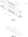
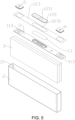
- FIG. 2 , FIG. 3 , FIG. 5 , and FIG. 6 show a battery
- the battery 100 includes a cover plate 1 and a casing 2 having an upper opening.
- the cover plate 1 is arranged at an opening 21 of the casing 2 and seals the opening 21.
- the cover plate 1 includes a cover plate body 11 and a high temperature resistant sheet 12, and the shape of the cover plate body 11 matches the shape of the opening 21 of the casing 2.
- the cover plate body 11 is adaptively formed in a long strip shape.
- the shape of the cover plate body 11 may also be correspondingly formed in other shapes as long as the cover plate body 11 can seal the opening 21 of the casing 2.
- a plurality of cells 3 are arranged in the sealed space formed by the casing 2 and the cover plate 1. The cells 3 are closely arranged inside the casing 2, are electrically connected to one another, and together form a charging and discharging assembly of the battery.
- both ends of the casing 2 may have openings in a length direction, and in this case, the cover plate 1 may cover the openings at both ends.
- the cover plate body 11 is provided with a first hole 111, and the first hole 111 is provided with an explosion-proof valve 4.
- the explosion-proof valve 4 may be a sheet structure attached in the first hole 111.
- the cover plate body 11 is further provided with two electrode holes 113 to allow each of a positive electrode 5 and a negative electrode 6 to penetrate through one of the electrode holes 113 and to protrude from the cover plate 1.
- the positive electrode 5 and the negative electrode 6 are electrically connected to the cell 3 in the casing 2.
- the first hole 111 is disposed at the center position of the cover plate body 11 in the length direction, and the electrode holes 113 are symmetrically arranged on both sides of the first hole 111 and are close to both ends of the cover plate 1 in the length direction.
- the first hole 111 is formed as a long strip with circular arcs at both ends, and the electrode holes 113 are formed in a substantially rectangular shape.
- the high temperature resistant sheet 12 is provided on an upper surface of the cover plate body 11.
- the high temperature resistant sheet 12 has substantially the same shape as the cover plate body 11 and is attached and fixed onto the cover plate body 11.
- the high temperature resistant sheet 12 may be a mica sheet, a ceramic sheet, a glass sheet, or the like.
- the material of the high temperature resistant sheet includes one of glass fiber, mica, ceramic, and ceramic rubber.
- the high temperature resistant sheet 12 has a thickness of 0.2 mm to 1 mm and can withstand a maximum temperature of 1,000 degrees Celsius.
- the high temperature substances generated in the battery may be sprayed out from the first hole 111 and may break through a weak portion of the high temperature resistant sheet 12.
- the cover plate 1 of the battery is also provided with the high temperature resistant sheet 12 to cover the cover plate body 11, the direct contact of the high temperature substances with the cover plate 11 is blocked, and that the structure of the cover plate 11 may not be damaged.
- the high temperature resistant sheet 12 covers the first hole 111, the high temperature substances are prevented from entering into the battery from the first hole 111. The probability of thermal runaway propagation is thereby lowered.
- the high temperature resistant sheet 12 has the weak portion, and at least a part of an orthographic projection of the weak portion is located in the first hole 111 in a direction perpendicular to the cover plate body 11.
- the weak portion includes two intersecting linear structures, and the intersection point of the two linear structures is located at the center of the first hole 111.
- linear structures formed by arranging a plurality of holes 1211 are shown, but not limited thereto.
- the weak portion may be a linear crack 1212.
- the shape of the weak portion is not limited to the shapes listed above and may be other shapes, as long as the weak portion may be easily broken when the air pressure increases.
- the weak portion is a structure that damages the high temperature resistant sheet 12 within the range of 1/4 to 3/4 of the thickness thereof.
- Each of the linear structures may be a straight line or a curved line, and the intersection point of the linear structures may not be located at the center of the first hole 111. Further, the number of linear structures is not limited to two as shown. In other embodiments, the weak portion may be one linear structure or three or more linear structures. When two or more linear structures are provided, the linear structures may also be parallel to each other or may intersect with extension lines.
- the first hole 111 is the weak portion of the high temperature resistant sheet 12, which can be broken under the condition of high temperature and high pressure inside the battery, so that a channel for the high temperature and high pressure inside the battery to be released to the outside is formed, and the battery is thus prevented from exploding or catching fire. That is, in the disclosure, through the arrangement of the high temperature resistant sheet 12, the original pressure relief function of the explosion-proof valve and the first hole 111 of one battery itself can be ensured to function normally, and the chain reaction caused by the thermal runaway of other batteries may be prevented from occurring. The overall safety and stability of the batteries is thus improved.
- the high temperature resistant sheet 12 further has a body portion 123 connected to a wall surface on a top portion of the cover plate body 11 and a shielding portion 122 separating the body portion 123 from the weak portion.
- the materials of the shielding portion 122 and the body portion 123 may be the same or different.
- a second mounting hole 1231 covered by the shielding portion 122 is provided on the body portion 123, and at least a part of the second mounting hole 1231 is located above the first hole 111.
- the body portion 123 extends along the length direction of the cover plate body 11, and both are formed in substantially the same shape and size.
- the shielding portion 122 is located above the first hole 111 and covers the first hole 111. In other embodiments, the shielding portion 122 may also cover part of the first hole 111.
- the second mounting hole 1231 is a through hole
- the shielding portion 122 is disposed above the body portion 123, and an area of the shielding portion 122 is greater than that of the through hole.
- the shielding portion 122 is spaced apart from the cover plate body 11, so as to prevent the shielding portion 122 from being worn by the structure on the cover plate body 11.
- An outer edge portion of the shielding portion 122 is pasted and fixed to an upper surface of the body portion 123, and the connection between the shielding portion 122 and the body portion 123 is thus achieved.
- the body portion 123 is two independent portions, the two portions are spaced apart to form the second mounting hole 1231, and the shielding portion 122 connects the two portions.
- the second mounting hole 1231 is a through hole, and the shielding portion 122 is embedded in the through hole.
- the shielding portion 122 is an arc-shaped structure protruding in a direction away from the first hole 111. Since the central portion of the shielding portion 122 protrudes in a direction away from the first hole 111, a gap is formed between the first hole 111 and the shielding portion 122. In this way, the air in the gap can produce a certain thermal insulation effect, so when the internal temperature of the battery increases, the speed of temperature rise on the top portion of the cover plate body 11 is slowed down.
- the cover plate body 11 has a boss 112 around an outer edge of the first hole 111.
- a protective film 13 is provided between the shielding portion 122 and the boss 112, the protective film 13 is arranged on the boss 112, and the protective film 13 can be attached to the boss 112.
- a distance between an upper surface of the protective film 13 and a lower surface of the shielding portion 122 ranges from 0.09 mm to 0.3 mm.
- the protective film 13 forms further protection on the first hole 111 without interfering with the normal explosion-proof and pressure relief of the battery.
- the protective film 13 may be a plastic film, a silicone mold, or the like. In other embodiments, there may be no protective film.
- a distance between the lower surface of the shielding portion 122 and an upper surface of the boss 112 is 0.08 mm to 0.1 mm. This distance range ensures that there is no contact between the shielding portion 122 and the first hole 111, and a sufficient space is thus formed.
- the air existing in the space acts as a heat insulating layer, and when the internal temperature of the battery increases, the speed of temperature rise on the top portion of the cover plate body 11 may be slowed down.
- the shielding portion 122 may also be disposed in contact with the boss 112, such as being attached to the boss 112 to cover the first hole 111.
- a thickness of the shielding portion 122 is less than or equal to a thickness of the body portion 123.
- the thickness of the shielding portion 122 is 0.2 mm to 1 mm, and this thickness range is more suitable for breaking of the shielding portion 122 when the pressure of the battery is released. As such, while the body portion 123 separates the high temperature substances from the cover plate body 11, the shielding portion 122 prevents the high temperature substances from falling into the inside of the battery from the first hole 111, and the safety and reliability of the battery is thus further improved.
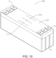
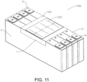
- FIG. 9 shows an exploded view in which the high temperature resistant sheet of the battery assembly 200 is separated from the cover plate body.
- the battery assembly 200 includes a plurality of the batteries 100 of the abovementioned embodiments.
- the batteries 100 are stacked along a direction perpendicular to the large surfaces of the batteries 100 to form the battery assembly 200, and the large surface of each of the batteries 100 is one surface in a thickness direction of the batteries 100. That is, each battery 100 has the same structure as the battery 100 in the above embodiment, and each battery 100 includes an independent high temperature resistant sheet.
- each battery in the battery assembly 200 is slightly different from that of the battery 100, for example, the structure of the high temperature resistant sheet of the cover plate is different.
- the high temperature resistant sheets of the batteries are connected together as a single piece structure, that is, a high temperature resistant piece is formed.
- the high temperature resistant sheets of the batteries 100 are independent of one another.
- the high temperature resistant piece may be integrally formed as a whole or may be formed by a plurality of high temperature resistant sheets standing together. During installation, after the cover plate body is packaged with the corresponding casing, the high temperature resistant piece formed by the connected high temperature resistant sheets 12 can be covered on the plurality of cover plate bodies 11.
- Each cover plate body 11 is also provided with a weak portion on the corresponding high temperature resistant sheet 12, and the structure of the weak portion is the same as that in the abovementioned embodiment.
- the thickness of the high temperature resistant sheet 12 is 0.2 mm to 1 mm, and a depth of the weak portion accounts for 1/4 to 3/4 of the thickness of the high temperature resistant sheet, that is, a thickness of the high temperature resistant piece is 0.2 mm to 1 mm.
- the high temperature resistant sheet 12 further has the body portion 123 connected to the wall surface on the top portion of the cover plate body 11 and the shielding portion 122 separating the body portion 123 from the weak portion.
- the materials of the shielding portion 122 and the body portion 123 may be the same or different.
- the second mounting hole 1231 covered by the shielding portion 122 is provided on the body portion 123, and at least a part of the second mounting hole 1231 is located above the first hole 111.
- the body portion 123 extends along the length direction of the cover plate body 11, and both are formed in substantially the same shape and size.
- the shielding portion 122 is located above the first hole 111 and covers the first hole 111. In other embodiments, the shielding portion 122 may also cover part of the first hole 111.
- An edge of the high temperature resistant piece 120 has a folded portion 7, and the folded portion extends towards the bottom of the battery assembly 200.
- the folded portion 7 may be fixed onto a side wall of an outer casing by bonding, heat riveting, or using screws.
- the high temperature resistant piece 120 as shown in FIG. 9 covers all regions of the cover plate body 11, the high temperature resistant piece 120 is surrounded by the folded portion 7, and the folded portion 7 is connected to a side wall of the battery assembly 200.
- the high temperature resistant piece 120 extends downwards along the narrow sides of the batteries, the high temperature resistant piece 120 does not cover all regions of the cover plate body 11, and the folded portion 7 is folded downwards to abut against the outer casing of the battery arranged on the outermost edge.
- this embodiment is a system embodiment corresponding to the abovementioned battery embodiment.
- This embodiment may be used together with the above battery embodiment to implement the relevant technical details mentioned in the above battery embodiment, which is still valid in this embodiment. Repeated description is not provided herein to avoid repetition. Correspondingly, the relevant technical details mentioned in this embodiment can also be applied to the abovementioned battery embodiment.
- an embodiment of the disclosure provides a battery including a casing, a cell, and a cover plate.
- the casing has an opening.
- the cell is disposed in the casing.
- the cover plate covers the opening of the casing.
- the cover plate includes a cover plate body and a high temperature resistant sheet.
- the cover plate body is provided with a first hole.
- the high temperature resistant sheet is disposed on an upper surface of the cover plate body and covers an upper opening of the first hole.
- the high temperature resistant sheet has a weak portion, and at least a part of an orthographic projection of the weak portion is located in the first hole in a direction perpendicular to the cover plate body.
- a thickness of the high temperature resistant sheet is 0.2 mm to 1 mm, and a depth of the weak portion accounts for 1/4 to 3/4 of the thickness of the high temperature resistant sheet.
- the weak portion includes a crack or a plurality of holes.
- the weak portion includes a plurality of linear structures, and at least two linear structures intersect or intersect with extension lines.
- the high temperature resistant sheet further has a body portion connected to the cover plate body and a shielding portion separating the body portion from the weak portion. At least a part of the shielding portion is located above the first hole, and the high temperature resistant sheet extends along a length direction of the cover plate body.
- the body portion is provided with a second mounting hole.
- the shielding portion covers the second mounting hole, and the second mounting hole at least partially overlaps the first hole in a height direction.
- the second mounting hole is a through hole
- the shielding portion is disposed above the body portion
- the second mounting hole is a through hole, and the shielding portion is embedded in the second mounting hole.
- the shielding portion is an arc-shaped piece protruding in a direction away from the first hole.
- the cover plate body is provided with a boss, and the shielding portion is located above the boss.
- a protective film is disposed between the shielding portion and the boss, the protective film is connected to the boss.
- a distance between an upper surface of the protective film and a lower surface of the shielding portion is 0.08 mm to 0.1 mm.
- a distance between a lower surface of the shielding portion and an upper surface of the boss is 0.09 mm to 0.3 mm.
- a thickness of the shielding portion is 0.2 mm to 1 mm, and the thickness of the shielding portion is less than or equal to a thickness of the body portion.
- the high temperature resistant sheet is a mica sheet or a glass sheet.
- An embodiment of the disclosure further provides a battery assembly including a plurality of batteries stacked along a direction perpendicular to large surfaces of the batteries.
- Each of the batteries includes a casing, a cell, and a cover plate.
- the casing has an opening.
- the cell is disposed in the casing.
- the cover plate covers the opening of the casing.
- the cover plate includes a cover plate body and a high temperature resistant sheet.
- the cover plate body is provided with a first hole.
- the high temperature resistant sheet is fixed to an upper surface of the cover plate body and covers an upper opening of the first hole.
- the high temperature resistant sheet has a weak portion, and at least a part of an orthographic projection of the weak portion is located in the first hole in a direction perpendicular to the cover plate body.
- the high temperature resistant sheets of the batteries are connected together as a single piece structure, or the high temperature resistant sheets of the batteries are separated from one another.
- a thickness of the high temperature resistant sheet is 0.2 mm to 1 mm, and a depth of the weak portion accounts for 1/4 to 3/4 of the thickness of the high temperature resistant sheet.
- the weak portion includes a crack or a plurality of holes.
- the high temperature resistant sheet further has a body portion connected to the cover plate body and a shielding portion separating the body portion from the weak portion. At least a part of the shielding portion is located above the first hole, and the high temperature resistant sheet extends along a length direction of the cover plate body.
- An embodiment of the disclosure further provides an electronic apparatus including the battery as described in the foregoing embodiments.
- the preferred embodiments of the disclosure have been described above in detail. However, it should be understood that aspects of the embodiments can be modified, if desired, to employ aspects, features, and concepts of various patents, applications, and publications to provide additional embodiments.
Landscapes
- Chemical & Material Sciences (AREA)
- Chemical Kinetics & Catalysis (AREA)
- Electrochemistry (AREA)
- General Chemical & Material Sciences (AREA)
- Inorganic Chemistry (AREA)
- Engineering & Computer Science (AREA)
- Manufacturing & Machinery (AREA)
- Sealing Battery Cases Or Jackets (AREA)
- Battery Mounting, Suspending (AREA)
- Gas Exhaust Devices For Batteries (AREA)
Applications Claiming Priority (2)
| Application Number | Priority Date | Filing Date | Title |
|---|---|---|---|
| CN202221887368.0U CN217768570U (zh) | 2022-07-20 | 2022-07-20 | 电池组件、电池模组和电子设备 |
| CN202221879355.9U CN217768556U (zh) | 2022-07-20 | 2022-07-20 | 盖板、电池及电子装置 |
Publications (1)
| Publication Number | Publication Date |
|---|---|
| EP4310997A1 true EP4310997A1 (en) | 2024-01-24 |
Family
ID=84569492
Family Applications (1)
| Application Number | Title | Priority Date | Filing Date |
|---|---|---|---|
| EP22215856.0A Pending EP4310997A1 (en) | 2022-07-20 | 2022-12-22 | Battery, battery assembly and electronic apparatus |
Country Status (3)
| Country | Link |
|---|---|
| US (1) | US20240030546A1 (cg-RX-API-DMAC7.html) |
| EP (1) | EP4310997A1 (cg-RX-API-DMAC7.html) |
| JP (1) | JP7557517B2 (cg-RX-API-DMAC7.html) |
Cited By (1)
| Publication number | Priority date | Publication date | Assignee | Title |
|---|---|---|---|---|
| EP4632919A1 (en) * | 2024-04-05 | 2025-10-15 | Samsung Sdi Co., Ltd. | Battery pack |
Families Citing this family (2)
| Publication number | Priority date | Publication date | Assignee | Title |
|---|---|---|---|---|
| EP4607674A1 (en) * | 2024-02-22 | 2025-08-27 | Volvo Truck Corporation | Cover structure for battery module and battery module comprising the cover structure |
| CN119481559A (zh) * | 2024-10-11 | 2025-02-18 | 中创新航科技集团股份有限公司 | 电池组件及电池包 |
Citations (4)
| Publication number | Priority date | Publication date | Assignee | Title |
|---|---|---|---|---|
| DE202020106526U1 (de) * | 2020-01-15 | 2020-12-03 | S.Z. Juhong Computer Telecommunication Technology CO., LTD. | Hochleistungslithiumbatterie-Abdeckplatte |
| DE202020106535U1 (de) * | 2020-01-11 | 2020-12-07 | S.Z. Juhong Computer Telecommunication Technology CO., LTD. | Montagestruktur für eine Volllasche einer Lithiumbatterie-Abdeckplatte |
| CN114497876A (zh) * | 2022-04-07 | 2022-05-13 | 中创新航科技股份有限公司 | 电池及电池组 |
| WO2022109884A1 (zh) * | 2020-11-25 | 2022-06-02 | 宁德时代新能源科技股份有限公司 | 电池单体及其制造方法和系统、电池以及用电装置 |
Family Cites Families (5)
| Publication number | Priority date | Publication date | Assignee | Title |
|---|---|---|---|---|
| JP5407683B2 (ja) * | 2009-09-10 | 2014-02-05 | トヨタ自動車株式会社 | 電池及び電池の製造方法 |
| US8658296B2 (en) * | 2010-02-25 | 2014-02-25 | Samsung Sdi Co., Ltd. | Rechargeable battery |
| KR101137366B1 (ko) * | 2010-05-20 | 2012-08-23 | 에스비리모티브 주식회사 | 이차전지 |
| KR20120095158A (ko) * | 2011-02-18 | 2012-08-28 | 삼성에스디아이 주식회사 | 이차 전지 |
| JP6109056B2 (ja) * | 2013-12-13 | 2017-04-05 | 日立オートモティブシステムズ株式会社 | 二次電池 |
-
2022
- 2022-12-21 JP JP2022204372A patent/JP7557517B2/ja active Active
- 2022-12-21 US US18/086,621 patent/US20240030546A1/en active Pending
- 2022-12-22 EP EP22215856.0A patent/EP4310997A1/en active Pending
Patent Citations (6)
| Publication number | Priority date | Publication date | Assignee | Title |
|---|---|---|---|---|
| DE202020106535U1 (de) * | 2020-01-11 | 2020-12-07 | S.Z. Juhong Computer Telecommunication Technology CO., LTD. | Montagestruktur für eine Volllasche einer Lithiumbatterie-Abdeckplatte |
| DE202020106526U1 (de) * | 2020-01-15 | 2020-12-03 | S.Z. Juhong Computer Telecommunication Technology CO., LTD. | Hochleistungslithiumbatterie-Abdeckplatte |
| WO2022109884A1 (zh) * | 2020-11-25 | 2022-06-02 | 宁德时代新能源科技股份有限公司 | 电池单体及其制造方法和系统、电池以及用电装置 |
| EP4071912A1 (en) * | 2020-11-25 | 2022-10-12 | Contemporary Amperex Technology Co., Limited | Battery cell and manufacturing method and system therefor, battery, and electrical apparatus |
| CN114497876A (zh) * | 2022-04-07 | 2022-05-13 | 中创新航科技股份有限公司 | 电池及电池组 |
| US20230327272A1 (en) * | 2022-04-07 | 2023-10-12 | Calb Co., Ltd. | Battery and battery apparatus |
Cited By (1)
| Publication number | Priority date | Publication date | Assignee | Title |
|---|---|---|---|---|
| EP4632919A1 (en) * | 2024-04-05 | 2025-10-15 | Samsung Sdi Co., Ltd. | Battery pack |
Also Published As
| Publication number | Publication date |
|---|---|
| JP2024014673A (ja) | 2024-02-01 |
| JP7557517B2 (ja) | 2024-09-27 |
| US20240030546A1 (en) | 2024-01-25 |
Similar Documents
| Publication | Publication Date | Title |
|---|---|---|
| US20240030546A1 (en) | Battery, battery assembly and electronic apparatus | |
| CN115699437B (zh) | 电池单体及其制造方法和系统、电池以及用电装置 | |
| WO2021022993A1 (zh) | 二次电池的盖组件及二次电池 | |
| KR20220017383A (ko) | 배터리 모듈, 그것을 포함하는 배터리 팩, 및 자동차 | |
| KR102806837B1 (ko) | 배터리 케이스, 배터리 셀, 배터리, 배터리 케이스 제조 방법 및 장치 | |
| CN107408718B (zh) | 具有原位形成的流体通道的可携带式电能储存装置 | |
| CN217719776U (zh) | 电芯及其盖板组件、锂电池及车辆 | |
| WO2022227774A1 (zh) | 电池及用电装置 | |
| CN216720195U (zh) | 电池模块、电池及用电装置 | |
| US20240363960A1 (en) | Battery, electrical device, and method and equipment for manufacturing battery | |
| JP7801063B2 (ja) | カバーアセンブリ、バッテリー、および電子デバイス | |
| CN114865213A (zh) | 动力电池保护结构、动力电池顶盖及动力电池 | |
| CN217158577U (zh) | 电池及用电设备 | |
| CN119908049A (zh) | 电池单体、电池、储能装置及用电装置 | |
| JP2024014673A5 (cg-RX-API-DMAC7.html) | ||
| CN218586256U (zh) | 防护组件、电池和用电设备 | |
| KR102322910B1 (ko) | 배터리 케이스와 이를 포함하는 배터리 팩 및 자동차 | |
| EP4310996A1 (en) | Battery and electronic device | |
| CN217822989U (zh) | 电池组件、电池模组和用电设备 | |
| CN218070149U (zh) | 电池、电池包及用电设备 | |
| CN221304850U (zh) | 一种壳体组件及电池模组 | |
| CN217768558U (zh) | 盖板、电池以及电子装置 | |
| CN217768556U (zh) | 盖板、电池及电子装置 | |
| CN217768559U (zh) | 电池及其盖板 | |
| CN217562755U (zh) | 动力电池保护结构、动力电池顶盖及动力电池 |
Legal Events
| Date | Code | Title | Description |
|---|---|---|---|
| PUAI | Public reference made under article 153(3) epc to a published international application that has entered the european phase |
Free format text: ORIGINAL CODE: 0009012 |
|
| STAA | Information on the status of an ep patent application or granted ep patent |
Free format text: STATUS: REQUEST FOR EXAMINATION WAS MADE |
|
| 17P | Request for examination filed |
Effective date: 20221222 |
|
| AK | Designated contracting states |
Kind code of ref document: A1 Designated state(s): AL AT BE BG CH CY CZ DE DK EE ES FI FR GB GR HR HU IE IS IT LI LT LU LV MC ME MK MT NL NO PL PT RO RS SE SI SK SM TR |
|
| RBV | Designated contracting states (corrected) |
Designated state(s): AL AT BE BG CH CY CZ DE DK EE ES FI FR GB GR HR HU IE IS IT LI LT LU LV MC ME MK MT NL NO PL PT RO RS SE SI SK SM TR |