EP4308387B1 - Pneumatique comprenant une structure de rigidification endurante - Google Patents
Pneumatique comprenant une structure de rigidification endurante Download PDFInfo
- Publication number
- EP4308387B1 EP4308387B1 EP22714490.4A EP22714490A EP4308387B1 EP 4308387 B1 EP4308387 B1 EP 4308387B1 EP 22714490 A EP22714490 A EP 22714490A EP 4308387 B1 EP4308387 B1 EP 4308387B1
- Authority
- EP
- European Patent Office
- Prior art keywords
- radially
- stiffening element
- radially inner
- anchoring
- stiffening
- Prior art date
- Legal status (The legal status is an assumption and is not a legal conclusion. Google has not performed a legal analysis and makes no representation as to the accuracy of the status listed.)
- Active
Links
Images








Classifications
-
- B—PERFORMING OPERATIONS; TRANSPORTING
- B60—VEHICLES IN GENERAL
- B60C—VEHICLE TYRES; TYRE INFLATION; TYRE CHANGING; CONNECTING VALVES TO INFLATABLE ELASTIC BODIES IN GENERAL; DEVICES OR ARRANGEMENTS RELATED TO TYRES
- B60C9/00—Reinforcements or ply arrangement of pneumatic tyres
- B60C9/02—Carcasses
-
- B—PERFORMING OPERATIONS; TRANSPORTING
- B60—VEHICLES IN GENERAL
- B60C—VEHICLE TYRES; TYRE INFLATION; TYRE CHANGING; CONNECTING VALVES TO INFLATABLE ELASTIC BODIES IN GENERAL; DEVICES OR ARRANGEMENTS RELATED TO TYRES
- B60C9/00—Reinforcements or ply arrangement of pneumatic tyres
- B60C9/02—Carcasses
- B60C9/04—Carcasses the reinforcing cords of each carcass ply arranged in a substantially parallel relationship
- B60C9/08—Carcasses the reinforcing cords of each carcass ply arranged in a substantially parallel relationship the cords extend transversely from bead to bead, i.e. radial ply
-
- B—PERFORMING OPERATIONS; TRANSPORTING
- B60—VEHICLES IN GENERAL
- B60C—VEHICLE TYRES; TYRE INFLATION; TYRE CHANGING; CONNECTING VALVES TO INFLATABLE ELASTIC BODIES IN GENERAL; DEVICES OR ARRANGEMENTS RELATED TO TYRES
- B60C2200/00—Tyres specially adapted for particular applications
- B60C2200/04—Tyres specially adapted for particular applications for road vehicles, e.g. passenger cars
Definitions
- the present invention relates to a tire, in particular for a passenger vehicle.
- tire is meant a bandage intended to form a cavity by cooperating with a mounting support, for example a rim, this cavity being capable of being pressurized to a pressure higher than atmospheric pressure.
- a tire according to the invention has a structure of substantially toroidal shape of revolution around a main axis of the tire, this main axis being coincident with the axis of rotation of the tire.
- the tire described comprises a crown extended radially inwards respectively on each side of the median plane of the tire by first and second sidewalls then by first and second beads intended to come into contact with a mounting support, for example a rim.
- Each first and second bead comprises a circumferential reinforcing element intended to allow the tire to be attached to the mounting support.
- the tire includes an internal surface defining a toric inflation cavity for the tire once the latter is mounted on the mounting support.
- the tire described in WO2020/128225 comprises a stiffening structure comprising first stiffening wire members extending continuously in the toric cavity from the first bead to the apex and second stiffening wire members extending continuously in the toric cavity from the second bead to the apex.
- Each first and second wire stiffening element is secured to each bead from which it extends by a bead interface between the wire stiffening element and a portion of the inner surface of the bead.
- each first and second wire stiffening element is secured to the crown of the tire by a crown interface between the wire stiffening element and a portion of the inner surface of the crown.
- Each bead and crown interface comprises a cushion made of an elastomeric mixture positioned between the wire stiffening element and the portion of the corresponding inner surface.
- the invention aims to improve the endurance of the stiffening structure.
- the or each stiffening element is anchored on the one hand, in one of the sidewalls and/or one of the beads and, on the other hand, in the crown, which makes it possible to obtain a securing by anchoring of the or each stiffening element in the tire.
- Such securing by anchoring is significantly more robust than the bead and crown interfaces described in WO2020/128225 .
- the anchoring makes it possible to avoid peeling stress and sliding of the or each stiffening element radially and axially towards the inside of the tire.
- the endurance of the stiffening structure of the tire according to the invention is significantly improved as demonstrated by the tests conducted and described below.
- the or each stiffening element By anchoring the or each stiffening element in the crown, the or each stiffening element is fixed axially and radially relative to the portion of the crown in which it is anchored. Similarly, by anchoring the or each stiffening element in the sidewall and/or the bead, the or each stiffening element is fixed axially and radially relative to the portion of the sidewall and/or the bead in which it is anchored.
- Each radially inner and outer reinforcement structure being respectively arranged in the sidewall or bead and in the crown of the tire, that is to say arranged radially inside the internal surface and embedded in the mass of materials constituting the sidewall or bead and in the crown, the or each stiffening element passes through the inner surface to anchor in or around the radially inner reinforcing structure at a radially inner anchor point and through the inner surface to anchor in or around the radially outer reinforcing structure at a radially outer anchor point.
- This feature in particular makes it possible to reduce the noise generated by the stiffening structure, noise which is dampened by the structure of the tire separating the or each radially inner and outer reinforcing structure from the mounting support.
- the or each stiffening element is anchored in or around each radially inner and outer reinforcement structure.
- the or each stiffening element can be anchored in the very structure of one or both of the radially inner and outer reinforcement structures, that is to say that the or each stiffening element penetrates at least partly into this structure, or even passes through it completely so that the structure forms a mechanical anchoring of the or each stiffening element in the structure.
- the or each stiffening element is anchored in the structure means, for example, that the or each stiffening element is wrapped around certain wire elements of the structure so as to pass through the structure itself.
- the or each stiffening element may be anchored around the structure itself of one or both of the radially inner and outer reinforcement structures, i.e. the or each stiffening element bears on this structure so that the structure absorbs part of the forces exerted on the or each stiffening element and anchors the structure in the sidewall or the bead and the crown.
- the or each stiffening element is anchored around the structure means, for example, that the or each stiffening element wraps around the peripheral wire elements of the structure without passing through it.
- the or each radially inner reinforcement structure is distinct from the or each circumferential reinforcement element located on the same side of the median plane of the tire, which makes it possible to very significantly reduce the propagation of the noise generated by the stiffening structure from the stiffening structure to the vehicle through the tire mounting support.
- the inventors behind the invention hypothesize that the noise generated by the stiffening structure is damped by the structure of the tire separating the or each radially inner reinforcement structure from each circumferential reinforcement element intended to allow the tire to be attached to its mounting support.
- This damping is the result of the fact that by being distinct from the or each circumferential reinforcement element located on the same side of the median plane of the pneumatic tire, the radially inner reinforcing structure is mechanically decoupled from the or each circumferential reinforcing element located on the same side of the median plane of the tire.
- the radially inner reinforcing structure and the or each circumferential reinforcing element located on the same side of the median plane of the tire are physically separated from each other by one or more decoupling materials, for example elastomeric materials, allowing one to be mechanically decoupled from the other.
- the toric inflation cavity is intended to be pressurized by an inflation gas once the tire is mounted on a mounting support, most often a rim.
- the stiffening structure makes it possible to simultaneously increase the radial stiffness, the axial stiffness and the drift stiffness of the tire compared to a conventional tire not comprising a stiffening structure but also compared to tires comprising other stiffening structures, such as that described in WO2017/005713 .
- Radial stiffness expressed in daN/mm
- Axial stiffness is the axial force generated by the tire when applying an axial displacement equal to 1 mm.
- Drift stiffness, expressed in daN/° is the axial force generated by the tire when rolling with an angle of 1° applied around the radial axis.
- the stiffening structure limits the radial deformation of the crown, during rolling, and in particular, the counter-deflection, that is to say the radial deformation, opposite the contact area of the rolling surface in contact with the ground.
- the stiffening structure makes it possible to limit the amplitude of the cyclic deformations of the tire, and in particular of its tread, and therefore to limit the resulting energy dissipation, which contributes to the reduction of the rolling resistance.
- the value of the contact area with the ground is not modified, which makes it possible to maintain the same grip performance as for the tire described in WO2017/005713 .
- the stiffening structure By increasing axial stiffness and drift stiffness, the stiffening structure will contribute to improving behavior under transverse stress, for example when drifting.
- the contact area with the ground ensures a more homogeneous distribution of contact pressures, which increases transverse grip.
- the stiffening structure participates at least partially in carrying the load applied to the tire such that this applied load is taken up jointly by the tire, thanks to its pneumatic rigidity and its rigidity intrinsic structural and by the stiffening structure.
- the or each stiffening element arranged opposite the contact area is put under tension.
- the or each stiffening element arranged opposite the contact area is subjected to buckling in compression.
- the presence of a stiffening structure makes it possible to reduce the contribution of the tire to carrying the load and therefore to be able to reduce its structural rigidity, for example by reducing the volume of the beads.
- the beads of a conventional tire dissipate a significant amount of energy, due to their volume and the hysteretic nature of their constituent elastomeric mixture. Reducing their volume thus makes it possible to significantly reduce rolling resistance.
- the stiffening elements are independent in pairs in the toric cavity, i.e. not mechanically linked together in the toric cavity of the tire, such that they have independent mechanical behaviors. For example, they are not linked together so as to form a network or a lattice in the cavity.
- the tire according to the invention has a substantially toric shape around an axis of revolution substantially coincident with the axis of rotation of the tire.
- This axis of revolution defines three directions conventionally used by those skilled in the art: an axial direction, a circumferential direction and a radial direction.
- axial direction is meant the direction substantially parallel to the axis of revolution of the tire, i.e. the axis of rotation of the tire.
- circumferential direction is meant the direction which is substantially perpendicular to both the axial direction and a radius of the tire (in other words, tangent to a circle whose center is on the axis of rotation of the tire).
- radial direction is meant the direction along a radius of the tire, that is to say any direction intersecting the axis of rotation of the tire and substantially perpendicular to this axis.
- median plane of the tire we mean the plane perpendicular to the axis of rotation of the tire which is located at mid-axial distance of the two beads and passes through the axial center of the crown reinforcement.
- equatorial circumferential plane of the tire is meant, in a meridian section plane, the plane passing through the equator of the tire, perpendicular to the median plane and to the radial direction.
- the equator of the tire is, in a meridian section plane (plane perpendicular to the circumferential direction and parallel to the radial and axial directions) the axis parallel to the axis of rotation of the tire and located equidistant between the radially outermost point of the tread intended to be in contact with the ground and the radially innermost point of the tire intended to be in contact with a support, for example a rim.
- meridian plane is meant a plane parallel to and containing the axis of rotation of the tire and perpendicular to the circumferential direction.
- radially inner, respectively radially outer is meant closer to the axis of rotation of the tire, respectively further from the axis of rotation of the tire.
- axially inner, respectively axially outer is meant closer to the median plane of the tire, respectively further from the median plane of the tire.
- bead is meant the radial portion of the tire intended to allow the tire to be attached to a mounting support, for example a wheel comprising a rim.
- each bead is in particular intended to be in contact with a hook of the rim allowing it to be attached.
- the bead is thus delimited radially internally by the radially inner end of the tire and radially externally by an axial straight line passing through the radially outermost point in contact with a standard rim within the meaning of the standard of the European Tyre and Rim Technical Organization or "ETRTO", 2020.
- Sidewall means the radial portion of the tire connecting the bead to the crown.
- the sidewall is delimited radially externally by a straight line perpendicular to the external surface of the tire passing through the point for which the angle between the tangent to the external surface of the tire and a straight line parallel to the axial direction passing through this point is equal to 30°.
- the radially outermost point is retained.
- the sidewall is delimited radially internally by an axial straight line passing through the radially outermost point in contact with a standard rim within the meaning of the European Tyre and Rim Technical Organization or "ETRTO" standard, 2020.
- any interval of values denoted by the expression "between a and b" represents the domain of values from greater than a to less than b (i.e., excluding the limits a and b), while any interval of values denoted by the expression “from a to b” signifies the domain of values from a to b (i.e., including the strict limits a and b).
- the tires of the invention are preferably intended for passenger vehicles as defined within the meaning of the standard of the European Tyre and Rim Technical Organisation or "ETRTO", 2020.
- Such a tire has a section in a meridian cutting plane characterized by a section height H and a nominal section width SW within the meaning of the standard of the European Tyre and Rim Technical Organisation or "ETRTO", 2020.
- the values of SW and H are indicated on the marking of the sidewall of the tire, for example as defined according to the ETRTO manual, 2020.
- passenger vehicle tires to which we will advantageously apply the invention are such that the H/S ratio, expressed as a percentage, is at most equal to 90, preferably at most equal to 80 and more preferably at most equal to 70 and is at least equal to 20, preferably at least equal to 30, and the nominal section width SW is at least equal to 115 mm, preferably at least equal to 155 mm and more preferably at least equal to 175 mm and at most equal to 385 mm, preferably at most equal to 315 mm, more preferably at most equal to 285 mm.
- the hook diameter D defining the diameter of the rim for mounting the tire, is at least equal to 12 inches, preferably at least equal to 16 inches and at most equal to 24 inches, preferably at most equal to 21 inches.
- the crown in a tire comprising a crown reinforcement and a carcass reinforcement, the crown comprises a tread intended to come into contact with the rolling ground and a crown reinforcement arranged radially inside the tread.
- the tire also comprises a carcass reinforcement anchored in each bead and extending radially in each sidewall and axially in the crown radially inside the crown reinforcement.
- the crown reinforcement comprises at least one crown layer comprising reinforcing elements. These reinforcing elements are preferably textile or metal wire elements.
- the carcass reinforcement is anchored in each bead by means of the circumferential reinforcing element(s).
- the carcass reinforcement comprises at least one carcass layer, the or each carcass layer comprising carcass wire reinforcement elements, each carcass wire reinforcement element extending substantially in a main direction forming with the circumferential direction of the tire, an angle, in absolute value, ranging from 80° to 90°.
- the stiffening structure comprises a plurality of stiffening elements circumferentially distributed in the toric cavity.
- the stiffening structure performs its function over the entire circumference of the tire.
- the circumferential distribution may be obtained by a stiffening structure in which the stiffening elements are distributed according to a constant circumferential pitch over the entire circumference of the tire or by a stiffening structure in which the stiffening elements are distributed periodically over the entire circumference of the tire or by a stiffening structure in which the stiffening elements are distributed randomly over the entire circumference of the tire.
- the or each stiffening element is not tight to a tire inflation gas.
- the or each stiffening element allows the inflation gas to pass through.
- the or each stiffening element does not delimit a secondary cavity under pressure of the tire.
- the stiffening element is permeable to the inflation gas so that the pressure is uniform in the toric cavity at all times and, in particular during inflation of the tire.
- the or each stiffening element is continuous between the first and second sidewalls or beads.
- the or each stiffening element is continuous, this also improves the transmission of forces between each first and second sidewall and/or bead which are thus distributed over the entire tire.
- the stiffening structure performs its function on both sides of the plane median of the tire which allows to obtain a homogeneous behavior of the tire.
- the tire comprises first and second radially external reinforcement structures distinct from each other. This makes it possible to reduce the mass of the reinforcement structure allowing the anchoring of the stiffening element(s) in the crown.
- first and second radially external reinforcement structures compared to a single radially external reinforcement structure makes it possible to limit the over-shrinkage of the crown, which makes it possible to maintain a regular contact area.
- the or each first stiffening element is distinct from the or each second stiffening element and discontinuous with respect to the or each second stiffening element.
- first and second radially external reinforcement structures are arranged axially on either side of the median plane of the tire, preferably substantially symmetrically with respect to the median plane of the tire.
- the axial distribution of the forces exerted by the stiffening elements on each first and second sidewall and/or bead and on the crown is improved.
- the portions extending on the one hand between the first anchoring points located on the same side of the median plane and on the other hand between the second anchoring points located on the other side of the median plane do not cross, which makes it possible to limit the axial buckling of the tread, i.e. the axial compression of the tread, in particular under conditions of high lateral stresses.
- a regular contact area is maintained, and on the other hand, the risk of deterioration of the crown reinforcement of the tire is reduced, in particular by avoiding the compression of the various constituent elements of the crown reinforcement, for example textile and metal wire reinforcement elements of the crown reinforcement.
- each first and second radially outer anchoring point is arranged such that the portion extending between the first anchoring points and the portion extending between the second anchoring points intersect in the toric cavity and/or that the first radially outer and radially inner anchoring points are arranged axially on two different sides of the median plane of the tire and/or that the second radially outer and radially inner anchoring points are arranged axially on two different sides of the median plane of the tire.
- the stiffening structure comprises several stiffening elements forming a continuous stiffening element so as to describe a boustrophedon trajectory between the first flank and/or the first bead and the second flank and/or the second bead passing through the apex.
- the robustness of the stiffening structure is further improved by removing ends of the stiffening element to be anchored in each sidewall or each bead.
- a continuous stiffening element forming the stiffening structure over the entire circumference of the tire.
- several continuous stiffening elements each forming a part of the stiffening structure over a part of the circumference of the tire.
- such a stiffening structure is relatively simple to manufacture because a single stiffening element is used, the laying law of which can be varied according to the different tire dimensions. If several stiffening elements distinct from each other were used, it would then be necessary to adjust their length for each tire dimension.
- the or each stiffening element passes through the internal surface to be anchored in or around the or one of the radially inner reinforcement structures at a radially inner anchoring point arranged radially at a radial distance ranging from 0.10 x H to 0.50 x H, preferably ranging from 0.10 x H to 0.35 x H from the radially innermost point of the tire, H being the section height of the tire.
- the propagation of noise generated by the stiffening structure from the stiffening structure to the vehicle through the tire mounting bracket is further reduced. Indeed, beyond a radial distance equal to 0.10 x H, the radially inner anchoring point is distant from the bead, and in particular from the circumferential reinforcing elements of the beads, for example bead wires, so that, for the sound waves generated by the stiffening structure to be significantly damped by the tire structure before reaching the circumferential reinforcing element which constitutes a significant noise transmission element between the tire and the mounting bracket.
- the radially inner anchoring point not to be too far away radially so as to allow effective axial force absorption between the stiffening structure and the sidewall or bead via the stiffening element and thus contribute to improving the axial rigidity.
- the or each stiffening element passes through the internal surface to be anchored in or around the or one of the radially external reinforcement structures at a radially external anchoring point arranged axially at an axial distance at most equal to 0.45 x SW, preferably ranging from 0.05 x SW to 0.45 x SW from the median plane of the tire, SW being the nominal section width of the tire.
- the or each stiffening element extends in a direction forming too small an angle with respect to the radial direction, which makes a lesser contribution to the axial and drift stiffnesses respectively.
- each stiffening element can be characterized geometrically, in particular by its mean section Sm, this characteristic not necessarily being identical for all the stiffening elements.
- the mean section Sm is the average of the sections obtained by cutting the stiffening element by all the cylindrical surfaces, coaxial with the tire and radially included in the inner toric cavity. In the most frequent case of a constant section, the mean section Sm is the constant section of the stiffening element.
- a first type of preferred stiffening element is said to be one-dimensional.
- a stiffening element is considered one-dimensional when the largest characteristic dimension Dmax of its mean section Sm is at most equal to 3 times the smallest characteristic dimension Dmin of its mean section Sm.
- a one-dimensional stiffening element has a wire-type mechanical behavior, that is to say that it can only be subjected to extension or compression forces along its mean line. This is the reason why a one-dimensional stiffening element is usually called a wire-type stiffening element.
- textile wire elements consisting of an assembly of elementary textile monofilaments, or metal cables, consisting of an assembly of elementary metal monofilaments, can be considered as one-dimensional stiffening elements, because their average section Sm being substantially circular, the aspect ratio R is equal to 1, therefore less than 3.
- a second type of stiffening element is said to be two-dimensional.
- a stiffening element is considered two-dimensional when the largest characteristic dimension Dmax of its mean section Sm is at least equal to 3 times the smallest characteristic dimension Dmin of its mean section Sm.
- a two-dimensional stiffening element has membrane-type mechanical behavior, i.e. it can only be subjected to extension or compression forces in its thickness defined by the smallest characteristic dimension Dmin of its mean section Sm.
- a stiffening element, with an aspect ratio R at least equal to 3 and at most equal to 50 is said to be two-dimensional of the strip type.
- a stiffening element stiffening, with an aspect ratio R at least equal to 50 is said to be two-dimensional film type.
- any stiffening element has a homogeneous structure, comprising a single constituent.
- This is the simplest structure envisaged, such as, for example, an elementary monofilament of a single material or a layer of a single material.
- any stiffening element has a composite structure, comprising at least two constituents. This is a structure constituted by an assembly of at least two elements, such as, for example, an assembly comprising several elementary monofilaments or an assembly of a first layer of a first material and a second layer of a second material.
- any stiffening element comprises a single material: for example, an elementary monofilament of a single material or an assembly comprising several elementary monofilaments of the same material.
- any stiffening element comprises at least two materials.
- there is a composite structure from the point of view of the materials for example, an assembly comprising elementary monofilaments of a first material and elementary monofilaments of a second material different from the first material. or a layer comprising elementary monofilaments or assemblies of elementary monofilaments embedded in a polymer matrix.
- the or each stiffening element is a wire stiffening element, preferably a textile wire stiffening element.
- the wire stiffening elements are identical, i.e. they have identical geometric characteristics and constituent materials.
- stiffening wire elements are usually called stays.
- the advantage of using stiffening wire elements is to have a stiffening structure with low mass and low hysteresis.
- the use of identical stiffening wire elements allows for a homogeneous distribution of forces between the stiffening elements.
- each wired stiffening element is preferably textile.
- textile it is meant that each wired stiffening element is non-metallic, for example made of a material chosen from a polyester, a polyamide, a polyketone, a polyvinyl alcohol, a cellulose, a mineral fiber, a natural fiber, an elastomeric material or a mixture of these materials.
- polyesters mention will be made for example of PET (polyethylene terephthalate), PEN (polyethylene naphthalate), PBT (polybutylene terephthalate), PBN (polybutylene naphthalate), PPT (polypropylene terephthalate), PPN (polypropylene naphthalate).
- Polyamides include aliphatic polyamides such as polyamides 4-6, 6, 6-6 (nylon), 11 or 12 and aromatic polyamides such as aramid.
- the material is a polyester or an aliphatic polyamide.
- each textile wire stiffening element is a textile assembly comprising one or more elementary monofilaments, twisted together or not.
- each wire stiffening element consists of an elementary monofilament.
- Each elementary monofilament has a diameter ranging from 5 ⁇ m to 0.80 mm.
- each textile wire stiffening element comprises one or more multifilament strand(s) each comprising several monofilaments having a diameter ranging from 5 ⁇ m to 20 ⁇ m.
- the number of monofilaments of each multifilament strand generally ranges from 100 to 10,000.
- each textile wire stiffening element comprises a multifilament strand comprising several monofilaments wound in a helix and each having a diameter ranging from 0.10 mm to 0.80 mm.
- the number of monofilaments generally ranges from 2 to 10.
- the number of capillaries between the monofilaments being low, it is not useful to sheath the textile wire stiffening element even if this can of course be considered.
- each textile wire stiffening element is coated with at least one aqueous adhesive composition, for example an RFL type glue or as described in the documents WO2013017422 , WO2017168107 .
- each wire stiffening element is metallic, for example an assembly of metal monofilaments, each metal monofilament having a diameter typically less than 50 ⁇ m, for example 10 ⁇ m.
- each wire stiffening element is made of an assembly of several metal monofilaments. In another embodiment, each wire stiffening element is made of a metal monofilament.
- the or each wire stiffening element extends continuously in the toric cavity from the sidewall or the bead to the crown in a main direction forming, with the circumferential direction of the tire, an angle ranging, in absolute value, from 85° to 90.
- the or each wire stiffening element extends continuously in the toric cavity from the sidewall or the bead to the crown in a main direction forming, with the circumferential direction of the tire, an angle ranging, in absolute value, from 45° to 75° as is explained in particular in WO2020128225 .
- the or each radially inner reinforcing structure and/or the or each radially outer reinforcing structure comprises at least one wire reinforcement element extending in a main direction forming with the circumferential direction of the tire an angle less than or equal to 10°, preferably less than or equal to 5° and more preferably substantially zero.
- the wire reinforcement element of the radially inner reinforcement structure is wound circumferentially over at most two complete turns, preferably over at most one complete turn around the axis of revolution.
- the wire reinforcement element of the radially inner reinforcement structure is a ring without free ends either because they are joined, for example by a sleeve, or because the ring is monolithic. It may also be envisaged that the wire reinforcement element of the radially inner reinforcement structure has two free ends.
- the wire reinforcement element of the radially inner revolution structure is metallic. This advantageously makes it possible, in certain embodiments, to use a metal wire reinforcement element identical to that used to manufacture the circumferential reinforcement element.
- the tire having a substantially toric shape around an axis of revolution
- the wire reinforcement element of the or each radially outer reinforcement structure is wound circumferentially over at least two complete turns around the axis of revolution and over at most ten complete turns around the axis of revolution.
- the wire reinforcement element of the radially outer reinforcement structure is a ring without free ends either because they are joined, for example by a sleeve, or because the ring is monolithic. It will be possible also consider that the wire reinforcement element of the radially outer reinforcement structure has two free ends.
- the wire reinforcement element of the radially outer structure of revolution is textile. This makes it possible to avoid localized stiffening of the crown. Thus, a correct flattening of the tire is maintained, compared to the case where the wire reinforcement element of the radially outer structure of revolution is metallic. Textile wire reinforcement elements with relatively low thermal contraction will be preferred.
- the or each stiffening element is wrapped at least partially around the or each wire reinforcement element.
- the direction in which the stiffening element extends in the toric cavity is non-collinear with the direction in which the stiffening element extends in the sidewall or bead and in the crown.
- a stiffening element is referred to as axially internal and externally anchored because of the axial offset of the radially external anchor point(s) of each stiffening element in the crown.
- a stiffening element is said to be axially externally anchored because its anchor point in the crown is axially further from the median plane of the tire than another axially internally anchored stiffening element whose anchor point in the crown is axially closer to the median plane of the tire.
- the radially outer anchor points are arranged on the same side of the median plane of the tire.
- the radially anchoring point inner of the or each axially inner anchoring stiffening element and the radially inner anchoring point of the or each axially outer anchoring stiffening element are radially and axially aligned on a same circumferential line.
- the radially inner anchoring point of the or each axially inner anchoring stiffening element and the radially inner anchoring point of the or each axially outer anchoring stiffening element are radially offset from each other, as contemplated in the fifth embodiment described below.
- each radially inner and outer anchoring point of the or each axially inner anchoring stiffening element is in the same meridian section plane as each radially inner and outer anchoring point of the or each axially outer anchoring stiffening element.
- each radially inner and outer anchoring point of the or each axially inner anchoring stiffening element is in a different meridian section plane than each radially inner and outer anchoring point of the or each axially outer anchoring stiffening element.
- each first and second radially inner anchoring point of the or each axially inner anchoring stiffening element and each first and second radially inner first anchoring point of the or each axially outer anchoring stiffening element are respectively radially aligned on the same circumferential line.
- each first and second radially inner first anchoring point of the or each axially outer anchoring stiffening element are respectively radially aligned on the same circumferential line.
- each radially inner anchoring point of the or each axially inner anchoring stiffening element and each first and second radially inner anchoring point of the or each axially outer anchoring stiffening element are respectively radially offset from each other, as envisaged in the fifth embodiment below.
- each first and second radially inner and outer anchoring point of the or each axially inner anchoring stiffening element is in the same meridian section plane as each first and second radially inner and outer anchoring point of the or each axially outer anchoring stiffening element.
- each first and second radially inner and outer anchoring point of the or each axially inner anchoring stiffening element is in a different meridian section plane than each first and second radially inner and outer anchoring point of the or each axially outer anchoring stiffening element.
- each first and second radially inner anchoring reinforcement structure of the or each axially inner anchoring stiffening element is respectively each first and second radially inner anchoring reinforcement structure of the or each axially outer anchoring stiffening element.
- each first and second radially inner anchoring reinforcement structure of the or each axially inner anchoring stiffening element is distinct from each first and second radially inner anchoring reinforcement structure of the or each axially outer anchoring stiffening element.
- the radially external reinforcement structure(s) for anchoring the or each axially internally anchored stiffening element is or are the radially external reinforcement structure(s) for anchoring the or each axially externally anchored stiffening element.
- the radially external reinforcement structure(s) for anchoring the or each axially internally anchored stiffening element of the radially external reinforcement structure(s) for anchoring the or each axially externally anchored stiffening element is or are the radially external reinforcement structure(s) for anchoring the or each axially externally anchored stiffening element.
- a stiffening element is referred to as a radially internal and external anchoring element because of the radial offset of the radially internal anchoring point(s) of each stiffening element in each sidewall and/or each bead.
- a stiffening element is said to be radially externally anchored because its anchoring point in each sidewall and/or each bead is radially further from the axis of rotation of the tire than another radially internal anchoring stiffening element whose anchoring point in the crown is radially closer to the axis of rotation of the tire.
- the radially outer anchor points are arranged on the same side of the median plane of the tire.
- the radially outer anchoring point of the or each radially inner anchoring stiffening element and the radially outer anchoring point of the or each radially outer anchoring stiffening element are radially and axially aligned on the same circumferential line.
- the radially outer anchoring point of the or each radially inner anchoring stiffening element and the radially outer anchoring point of the or each radially outer anchoring stiffening element are axially offset from each other, as contemplated in the fourth embodiment described above.
- each radially inner and outer anchoring point of the or each radially inner anchoring stiffening element is in the same meridian section plane as each radially inner and outer anchoring point of the or each radially outer anchoring stiffening element.
- each radially inner and outer anchoring point of the or each radially inner anchoring stiffening element is in a different meridian section plane than each radially inner and outer anchoring point of the or each radially outer anchoring stiffening element.
- each first and second radially outer anchoring point of the or each radially inner anchoring stiffening element and each first and second radially outer first anchoring point of the or each radially outer anchoring stiffening element are respectively axially aligned on the same circumferential line.
- each first and second radially outer first anchoring point of the or each radially inner anchoring stiffening element and each first and second radially outer first anchoring point of the or each radially outer anchoring stiffening element are respectively axially offset from each other, as is envisaged in the fourth embodiment described above.
- each first and second radially inner and outer anchoring point of the or each radially inner anchoring stiffening element is in the same meridian section plane as each first and second radially inner and outer anchoring point of the or each radially outer anchoring stiffening element.
- each first and second radially inner and outer anchoring point of the or each radially inner anchoring stiffening element is in a different meridian section plane than each first and second radially inner and outer anchoring point of the or each radially outer anchoring stiffening element.
- each first and second radially inner anchoring reinforcement structure of the or each radially inner anchoring stiffening element is each first and second radially inner anchoring reinforcement structure. internal anchoring structure of the or each radially external anchoring stiffening element.
- each first and second radially internal anchoring reinforcement structure of the or each radially internal anchoring stiffening element is distinct from each first and second radially internal anchoring reinforcement structure of the or each radially external anchoring stiffening element.
- the radially external anchoring reinforcement structure(s) of the or each radially internal anchoring stiffening element is or are the radially external anchoring reinforcement structure(s) of the or each radially external anchoring stiffening element.
- the radially external anchoring reinforcement structure(s) of the or each radially internal anchoring stiffening element of the radially external anchoring reinforcement structure(s) of the or each radially external anchoring stiffening element is or are the radially external anchoring reinforcement structure(s) of the or each radially external anchoring stiffening element.
- the fourth and fifth embodiments may be combined so as to differentiate the anchoring in the crown and each sidewall and/or each bead and have radially and axially internal stiffening elements or radially and axially external stiffening elements or radially internal and axially external stiffening elements or even radially external and axially internal stiffening elements.
- the or each radially inner reinforcing structure and/or the or each radially outer reinforcing structure comprises a fabric, a knit or a nonwoven, preferably a fabric or a knit.
- the or each stiffening element passes through the fabric, knit or nonwoven, preferably through the fabric or knit of the or each radially inner reinforcing structure and/or the or each radially outer reinforcing structure.
- the tire comprising a carcass reinforcement anchored in each bead and extending into each sidewall
- the or each radially inner reinforcing structure comprises a portion of the carcass reinforcement extending radially into the sidewall and/or the bead.
- the tire comprising a carcass reinforcement extending axially in the crown
- the or each radially outer reinforcing structure comprises a portion of the carcass reinforcement extending axially in the crown.
- the carcass reinforcement comprising wire carcass reinforcement elements, the or each stiffening element is wound at least partly around one or more of the wire carcass reinforcement elements of the portion of the carcass reinforcement extending radially in the sidewall and/or the bead and/or of the portion of the carcass reinforcement extending axially in the crown.
- a reference X, Y, Z is shown corresponding to the usual axial (Y), radial (Z) and circumferential (X) directions of a tire.
- the tire 10 has a substantially toric shape around an axis of revolution substantially parallel to the axial direction Y.
- the tire 10 is intended for a passenger vehicle and has a dimension of 275/35ZR19. In the various figures, tire 10 is shown in new condition, i.e. not yet having been driven.
- the tire 10 comprises a crown 12 comprising a tread 14 intended to come into contact with a ground when rolling and a crown reinforcement 16 extending in the crown 12 in the circumferential direction X.
- the tire 10 also comprises a sealing layer 18 to an inflation gas.
- the crown reinforcement 16 comprises a working reinforcement 20 and a hoop reinforcement 22.
- the working reinforcement 20 comprises at least one working layer and here comprises two working layers 24, 26.
- the working reinforcement 20 is made up of the two working layers 24, 26.
- the radially inner working layer 24 is arranged radially inside the radially outer working layer 26.
- the hoop reinforcement 22 comprises at least one hoop layer and here comprises a hoop layer 28.
- the hoop reinforcement 22 here consists of the hoop layer 28.
- the crown reinforcement 16 is radially surmounted by the tread 14.
- the hoop reinforcement 22, here the hoop layer 28, is arranged radially outside the working reinforcement 20 and is therefore radially intercalated between the working reinforcement 20 and the tread 14.
- the tire 10 comprises first and second sidewalls 30A, 30B extending the crown 12 radially inwards.
- the second sidewall 30B is located on the other side than the first sidewall 30A relative to the median plane M.
- the tire 10 further comprises first and second beads 32A, 32B extending each first and second sidewall 30A, 30B radially inwards, respectively.
- the second bead 32B is located on the other side than the first bead 32A relative to the median plane M.
- Each first and second sidewall 30A, 30B respectively connects each first and second bead 32A, 32B to the crown 12.
- An internal surface 33 intended to be in contact with the inflation gas of the tire, delimits a toric cavity 35 for inflation of the tire 10.
- the internal surface 33 is here carried by the sealing layer 18.
- Each first and second bead 32A, 32B respectively comprises a first and second circumferential reinforcement element 40A, 40B, here a bead allowing the attachment of the tire 10 to a mounting support
- the tire 10 comprises a carcass reinforcement 34 anchored in each first and second bead 32A, 32B, in this case is wrapped around each first and second circumferential reinforcement element 40A, 40B.
- the carcass reinforcement 34 extends radially in each sidewall 30 and radially internally to the crown reinforcement 16 axially in the crown 12.
- the crown reinforcement 16 is arranged radially between the tread 14 and the carcass reinforcement 34.
- the carcass reinforcement 34 comprises at least one carcass layer and here comprises a single carcass layer 36. In this case, the carcass reinforcement 34 is made up of the single carcass layer 36.
- Each working layer 24, 26 of hooping 28 and carcass 36 comprises an elastomeric matrix in which one or more wire reinforcement elements of the corresponding layer are embedded.
- the hoop reinforcement 22, here the hoop layer 28, is delimited axially by two axial edges 28A, 28B of the hoop reinforcement 22.
- the hoop reinforcement 22 comprises one or more hoop wire reinforcement elements 280 wound circumferentially helically so as to extend axially from the axial edge 28A to the other axial edge 28B of the hoop layer 28 in a main direction D0 of each hoop wire reinforcement element 280.
- the main direction D0 forms, with the circumferential direction X of the tire 10, an angle AF, in absolute value, less than or equal to 10°, preferably less than or equal to 7° and more preferably less than or equal to 5°.
- AF -5°.
- the radially inner working layer 24 is delimited axially by two axial edges 24A, 24B.
- the radially inner working layer 24 comprises working wire reinforcement elements 240 extending axially from the axial edge 24A to the other axial edge 24B, each substantially parallel to the other in a main direction D1.
- the radially outer working layer 26 is delimited axially by two axial edges 26A, 26B.
- the radially outer working layer 26 comprises working wire reinforcement elements 260 extending axially from the axial edge 26A to the other axial edge 26B, each substantially parallel to the other in a main direction D2.
- the main direction D1 along which each working wire reinforcement element 240 of the radially inner working layer 24 extends and the main direction D2 along which each working wire reinforcement element 260 of the other of the radially outer working layer 26 extends form, with the circumferential direction X of the tire 10, angles AT1 and AT2 respectively of opposite orientations.
- Each main direction D1, D2 forms, with the circumferential direction X of the tire 10, an angle AT1, AT2 respectively, in absolute value, strictly greater than 10°, preferably ranging from 15° to 50° and more preferably ranging from 15° to 30°.
- the carcass layer 36 is delimited axially by two axial edges 36A, 36B.
- Each hoop wire reinforcement element 280 conventionally comprises two multifilament strands comprising a multifilament strand consisting of a yarn of aliphatic polyamide monofilaments, here nylon with a count equal to 140 tex and a multifilament strand consisting of a yarn of aromatic polyamide monofilaments, here aramid with a count equal to 167 tex, these two multifilament strands being individually helical at 290 turns per meter in one direction and then helical together at 290 turns per meter in the opposite direction. These two multifilament strands are wound in a helix around each other.
- any other hoop wire reinforcement element known to those skilled in the art may be used.
- Each working wire reinforcement element 240, 260 is an assembly of four steel monofilaments comprising an inner layer of two steel monofilaments initially wound in a helix at an infinite pitch and an outer layer of two steel monofilaments initially wound in a helix at a pitch of 14.3 mm in one direction, the four monofilaments then being wound at a pitch of 14.3 mm in the opposite direction, each steel monofilament having a diameter equal to 0.26 mm.
- each working wire reinforcement element 240, 260 is made of a steel monofilament having a diameter equal to 0.30 mm.
- each working wire reinforcement element is an assembly of two monofilaments wound together in a helix having a diameter equal to 0.30 mm. More generally, steel monofilaments have diameters ranging from 0.25 mm to 0.32 mm. Obviously, any other wire reinforcement element known to those skilled in the art can be used.
- Each 340 carcass wire reinforcement element conventionally comprises two multifilament strands, each multifilament strand being made up of a polyester monofilament yarn, here PET, these two multifilament strands being individually helical at 270 turns per meter in one direction and then helical together at 270 turns per meter in the opposite direction.
- Each of these multifilament strands has a count equal to 334 tex. In other variants, counts equal to 144 tex and twists equal to 420 turns per meter or counts equal to 220 tex and twists equal to 240 turns per meter may be used.
- the tire 10 comprises a stiffening structure 50 comprising several stiffening elements 52 extending continuously in the toric cavity 35.
- the stiffening elements 52 are distributed circumferentially in the toric cavity 35.
- the stiffening elements 52 are distributed circumferentially according to an angular repetition pitch preferably between 1 degree and 5 degrees, preferably between 1 degree and 3 degrees.
- the stiffening structure 50 has between 72 and 360 stiffening elements 52, preferably between 120 and 360 stiffening elements 52, and here 240 stiffening elements 52.
- the number of stiffening elements 52 makes it possible to obtain a good compromise between a number of stiffening elements 52 which is on the one hand sufficiently high to obtain effective stiffening of the tire 10, and on the other hand sufficiently moderate to be able to arrange a corresponding number of passages 1500 in the core 1000 without excessively weakening the structure of the core 1000 or complicating the demolding operations as explained below.
- Each stiffening element 52 is a textile wire stiffening element, here consisting of an assembly of three multifilament strands of polyester, here of PET, these three multifilament strands being individually helical at 220 turns per meter in one direction and then helical together at 220 turns per meter in the opposite direction. Each of these multifilament strands has a count equal to 220 tex.
- Each wire stiffening element 52 extends continuously from the first flank 30A and/or the first bead 32A to the second flank 30B and/or the second bead 32B passing through the apex 12 and here from the first flank 30A to the second flank 30B passing through the apex 12.
- the main direction in which each stiffening element 52 extends in the toric cavity 35 forms, with the circumferential direction X, an angle ranging, in absolute value, from 85° to 90°.
- the stiffening structure 50 also comprises first and second radially inner reinforcement structures 60A, 60B respectively arranged in each first and second flank 30A, 30B and/or in each first and second bead 32A, 32B, and here respectively arranged in each first and second flank 30A, 30B.
- Each first and second radially inner reinforcement structure 60A, 60B is respectively distinct from each first and second circumferential reinforcement element 40A, 40B located on the same side of the median plane as each first and second flank 30A, 30B respectively.
- each first and second radially inner reinforcement structure 60A, 60B is arranged radially to the outside respectively of each first and second circumferential reinforcement element 40A, 40B.
- Each first and second radially inner reinforcing structure 60A, 60B respectively comprises a first and second metallic wire reinforcement element 62A, 62B comprising here an assembly of an inner layer of four elementary metallic monofilaments of 0.35 mm wound in a helix at a pitch of 5 mm and an outer layer of nine elementary metallic monofilaments of 0.35 mm wound in a helix around the inner layer at a pitch of 10 mm.
- Each wire reinforcement element 62A, 62B extends in a main direction forming with the circumferential direction X an angle less than or equal to 10°, preferably less than or equal to 5° and here substantially zero as is visible on the figures 3 And 4 .
- Each first and second wire reinforcement element 62A, 62B of each first and second radially inner reinforcement structure 60A, 60B is circumferentially wound over at most two complete turns, and here over at most one complete turn around the axis of revolution Y.
- each first and second radially inner reinforcement structure 60A, 60B has relatively high extension and bending rigidities. Furthermore, still with the aim of optimizing the anchoring of each stiffening element 52, each first and second radially inner reinforcement structure 60A, 60B is embedded in a mass of one or more materials, preferably elastomeric, whose nominal secant modulus at 10% elongation is greater than or equal to 20 MPa, preferably 30 MPa and here equal to 56 MPa. The measurement is carried out in accordance with the French standard NF T 46-002 of September 1988.
- the nominal secant modulus calculated by reducing to the initial section of the test piece (or apparent stress, in MPa) at 10% elongation is measured in second elongation (i.e. after accommodation). This tensile measurement is carried out under normal conditions of temperature (23 ⁇ 2°C) and hygrometry (50 ⁇ 5% relative humidity), according to the French standard NF T 40-101 (December 1979).
- the stiffening structure 50 further comprises first and second radially outer reinforcement structures 70A, 70B respectively arranged in the crown 12.
- the first and second radially outer reinforcement structures 70A, 70B are arranged axially on either side of the median plane M of the tire 10 and here substantially symmetrically with respect to the median plane M of the tire 10.
- Each radially outer reinforcement structure 70A, 70B is arranged radially inside the carcass reinforcement 34.
- Each first and second radially outer reinforcing structure 70A, 70B respectively comprises a first and second textile wire reinforcement element 72A, 72B comprising here an assembly of two multifilament strands each consisting of a yarn of aromatic polyamide monofilaments, here of aramid with a count equal to 330 tex and a multifilament strand consisting of a yarn of aliphatic polyamide monofilaments, here of nylon with a count equal to 188 tex, each of the multifilament strands being individually helical at 270 turns per meter in one direction and then helical together at 270 turns per meter in the opposite direction.
- These three multifilament strands are helically wound around each other.
- Each wire reinforcement element 72A, 72B extends in a main direction forming with the circumferential direction X an angle less than or equal to 10°, preferably less than or equal to 5° and here substantially zero as can be seen. on the figures 3 And 5 .
- Each first and second wire reinforcement element 72A, 72B of each first and second radially outer reinforcement structure 70A, 70B is circumferentially wound over at least two complete turns and at most ten complete turns around the axis of revolution, and here over four complete turns around the axis of revolution Y.
- each first and second radially external reinforcement structure 70A, 70B has a relatively high extension rigidity and a relatively low bending rigidity in order to limit over-shrinkage of the crown 12 and not risk damaging the flattening of the tread 14.
- each first and second radially external reinforcement structure 70A, 70B is embedded in a mass of one or more materials, preferably elastomeric, whose nominal secant modulus at 10% elongation is greater than or equal to 2.5 MPa and preferably less than or equal to 15 MPa, more preferably less than or equal to 10 MPa and even more preferably less than or equal to 5 MPa and here equal to 3 MPa.
- Each stiffening element 52 is anchored, in the first flank 30A, around the first radially inner reinforcement structure 60A and in the second flank 30B, around the second radially inner reinforcement structure 60B.
- each stiffening element 52 is wound at least in part around each first and second wire reinforcement element 62A, 62B.
- Each stiffening element 52 is also anchored, in the crown 12, around each first and second radially outer reinforcement structure 70A, 70B.
- each stiffening element 52 is wound at least in part around each first and second wire reinforcement element 72A, 72B.
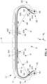
- Each stiffening element 52 passes through the inner surface 33 at a first radially inner anchoring point 54A to anchor around the first radially inner reinforcement structure 60A and at a first radially outer anchoring point 56A to anchor around the first radially outer reinforcement structure 70A.
- the stiffening element 52 passes through the inner surface 33 at a second radially inner anchoring point 54B to anchor around the second radially inner reinforcement structure 60B and at a second radially outer anchoring point 56B to anchor around the second radially outer reinforcement structure 70B.
- each stiffening element 52 comprises portions 521, 522 respectively embedded in each flank 30A, 30B, first and second portions 523, 524 extending in the toric cavity 35 respectively between the first radially inner 54A and outer 56A anchoring points and between the second radially inner 54B and outer 56B anchoring points as well as a portion 525 embedded in the crown 12. arranged between the first and second portions 523, 524.
- each portion 521, 522 has a relatively significant length, here greater than or equal to 20 mm and is coupled to a length greater than or equal to 1 mm of each radially internal reinforcement structure 60A, 60B.
- the first radially outer anchoring point 56A is arranged axially on the same side as the first radially inner anchoring point 54A and as the first radially inner structure 60A relative to the median plane M.
- the second radially outer anchoring point 56B is arranged axially on the same other side as the second radially inner anchoring point 54B and as the second radially inner structure 60B relative to the median plane M.
- Each first and second radially inner anchoring point 54A, 54B and outer 56A, 56B is arranged such that the first and second portions 523, 524 do not intersect in the toric cavity 35.
- Each first and second radially outer anchor point 56A, 56B is arranged axially respectively at an axial distance D1, D2 at most equal to 0.45 x SW, preferably ranging from 0.05 x SW to 0.45 x SW from the median plane M of the tire 10, SW being the nominal section width of the tire 10.
- the nominal section width is as defined in the ETRTO 2020 standard manual and is notably visible on the marking affixed to at least one of the sidewalls 30A, 30B of the tire 10 in the form SW/AR ⁇ V U ⁇ with SW designating the nominal section width, AR designating the nominal aspect ratio, ⁇ designating the structure and possibly being R or ZR, V designating the nominal rim diameter, U designating the load index and ⁇ designating the speed symbol.
- the nominal section width SW and the nominal aspect ratio AR are those of the dimension marking inscribed on the sidewall of the tire and in accordance with the ETRTO 2020 standard manual.
- the stiffening elements 52 form a continuous stiffening element so as to describe a boustrophedon trajectory between the first flank 30A and the second flank 30B passing through the apex 12.
- stiffening elements 52 that are separate and therefore discontinuous from each other.
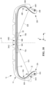
- the stiffening structure 50 of the tire 10 according to the second embodiment comprises first and second stiffening elements 52A, 52B distinct from each other.
- Each first stiffening element 52A is anchored around the first radially inner reinforcement structure 60A arranged in the first flank 30A and around the first radially outer reinforcement structure 70A arranged in the crown 12.
- Each second stiffening element 52B is anchored around a second radially inner reinforcement structure 60B arranged in the second flank 30B and around the second radially outer reinforcement structure 70B arranged in the crown 12 such that each first stiffening element 52A extends continuously in the toric cavity 35 from the first flank 30A to the crown 12 and such that each second stiffening element 52B extends continuously in the toric cavity 35 from the second flank 30B to the crown 12.
- the first stiffening elements 52A form a first continuous stiffening element so as to describe a boustrophedon trajectory between the first flank 30A and the apex 12.
- the second stiffening elements 52B form a second continuous stiffening element so as to describe a boustrophedon trajectory between the first flank 30B and the apex 12.
- Each first and second stiffening element 52A, 52B comprises a first and second portion 521A, 521B respectively embedded in each first and second flank 30A, 30B, a first and second portion 523A, 523B extending in the toric cavity 35 respectively between the first radially inner 54A and outer 56A anchor points and between the second radially inner 54B and outer 56B anchor points as well as a first and second portion 525A, 525B embedded in the crown 12.
- each first and second portion 523A', 523B' of stiffening elements 52A', 52B' has been shown to be continuous with each first and second stiffening element 52A, 52B but arranged outside the meridian plane of the figure 6 .
- the first radially outer anchoring point 56A is arranged axially on the same side as the first radially inner anchoring point 54A and the first radially inner structure 60A relative to the median plane M.
- the second radially outer anchoring point 56B is arranged axially on the same side as the second radially inner anchoring point 54B and the second radially inner structure 60B relative to the median plane M.
- Each first and second radially inner anchor point 54A, 54B and outer anchor point 56A, 56B is arranged such that the first and second portions 523A, 523B do not intersect in the toric cavity 35.
- the stiffening structure 50 does not comprise two radially external reinforcement structures but a single radially external reinforcement structure, as is the case for the third embodiment described below.
- the stiffening structure of the tire 10 according to the third embodiment comprises a single radially outer reinforcement structure 73.
- Each stiffening element 52 is anchored around the first radially inner reinforcement structure 60A, around the radially outer reinforcement structure 73 arranged in the crown 12 and around the second radially inner reinforcement structure 60B such that each stiffening element 52 extends continuously from the first sidewall 30A to the second sidewall 30B passing through the crown 12.
- the stiffening structure 50 comprises stiffening elements 52 with axially external anchoring and stiffening elements 53 with axially internal anchoring.
- the stiffening structure 52 comprises first and second radially external reinforcement structures 70A, 70B arranged on either side and substantially symmetrically with respect to the median plane M.
- Each axially externally anchored stiffening element 52 is anchored around the first radially internal reinforcement structure 60A, around the first and second radially external reinforcement structures 70A, 70B and around the second radially internal reinforcement structure 60B such that each axially externally anchored stiffening element 52 extends continuously from the first flank 30A to the second flank 30B passing through the crown 12.
- Each axially externally anchored stiffening element 52 comprises a first portion 523 extending in the toric cavity 35 between a first radially internal anchoring point 54A at which each axially externally anchored stiffening element 52 passes through the internal surface 33 to be anchored around the first radially internal reinforcement structure.
- Each axially outer anchoring stiffening element 52 comprises a second portion 524 extending into the toric cavity 35 between a second radially inner anchoring point 54B at which each axially outer anchoring stiffening element 52 passes through the inner surface 33 to anchor around the second radially inner reinforcing structure 60B and a second radially outer anchoring point 56B at which each axially outer anchoring stiffening element 52 passes through the inner surface 33 to anchor around the first and second radially outer reinforcing structures 70A, 70B.
- Each axially internally anchored stiffening element 53 is anchored around the first radially internal reinforcement structure 60A, around the first and second radially external reinforcement structures 70A, 70B and around the second radially internal reinforcement structure 60B such that each second stiffening element 53 extends continuously from the first flank 30A to the second flank 30B passing through the apex 12.
- Each axially internally anchored stiffening element 53 comprises a first portion 533 extending in the toric cavity 35 between a first radially internal anchoring point 55A at which each axially internally anchored stiffening element 53 passes through the internal surface 33 to be anchored around the first radially internal reinforcement structure 60A and a first radially external anchoring point 57A at which each axially internally anchored stiffening element 53 passes through the internal surface 33 to be anchored around the first radially internal reinforcement structure 60A and a first radially external anchoring point 57A at which each axially internally anchored stiffening element 53 passes through the internal surface 33 to be anchored around the first radially internal reinforcement structure 60A.
- Each axially inner anchoring stiffening element 53 comprises a second portion 534 extending in the toric cavity 35 between a second radially inner anchoring point 55B at which each axially inner anchoring stiffening element 53 passes through the internal surface 33 to anchor around the second radially inner reinforcement structure 60B and a second radially outer anchoring point 57B at which each axially inner anchoring stiffening element 53 passes through the internal surface 33 to anchor in the first and second radially outer reinforcement structures 70A, 70B.
- each first and second radially inner anchoring point 54A, 55A, 54B, 55B and outer anchoring point 56A, 57A, 56B, 57B of each axially inner anchoring stiffening element 53 and outer anchoring stiffening element 52 is arranged such that portion 533 and portion 534 do not intersect in the toric cavity, portion 523 and portion 524 do not intersect in the toric cavity, the first points radially outer anchor points 56A, 57A and radially inner anchor points 54A, 55A are arranged axially on the same side of the median plane of the tire, and the second radially outer anchor points 56B, 57B and radially inner anchor points 54B, 55B are arranged axially on the same other side of the median plane of the tire.
- Each first and second radially outer anchoring point 57A, 57B of each axially inner anchoring stiffening element 53 is arranged axially inside relative to each first and second radially outer anchoring point 56A, 56B of each axially outer anchoring stiffening element 52, respectively.
- each first radially inner anchor point 55A and each first radially inner anchor point 54A are radially and axially aligned on the same circumferential line.
- each second radially inner anchor point and each second radially inner anchor point 54B are radially and axially aligned on the same circumferential line.
- each first and second radially inner and outer anchoring point 55A, 55B, 57A, 57B is in the same meridian section plane as each first and second radially inner and outer anchoring point 54A, 54B, 56A, 56B. It may also be envisaged, in a variant not illustrated, that each first and second radially inner and outer anchoring point 55A, 55B, 57A, 57B is in a different meridian section plane than each first and second radially inner and outer anchoring point 54A, 54B, 56A, 56B.
- each first and second radially inner anchoring reinforcement structure 60A, 60B of each axially inner anchoring stiffening element 53 is each first and second radially inner anchoring reinforcement structure 60A, 60B of each axially outer anchoring stiffening element 52.
- the first and second radially outer anchoring reinforcement structures 70A, 70B of each axially inner anchoring stiffening element 53 are the radially outer anchoring reinforcement structures 70A, 70B of each axially outer anchoring stiffening element 52. In a variant, they could be considered distinct.
- the stiffening structure 50 comprises stiffening elements 52 with radially and axially external anchoring and stiffening elements 53 with radially and axially internal anchoring.
- the stiffening structure 50 comprises a first radially external reinforcement structure 60A anchoring of each radially and axially external anchoring stiffening element 52 arranged in the first flank 30A and a first radially internal reinforcement structure 61A for anchoring each radially and axially internal anchoring stiffening element 53 arranged in the first flank 30A and distinct from the first radially external reinforcement structure 60A but also from the first circumferential reinforcement element 40A.
- the stiffening structure 50 also comprises a second radially external reinforcement structure 60B for anchoring each radially and axially external anchoring stiffening element 52 arranged in the second flank 30B and a second radially internal reinforcement structure 61B for anchoring each radially and axially internal anchoring stiffening element 53 arranged in the second flank 30B and distinct from the second radially external reinforcement structure 60B but also from the second circumferential reinforcement element 40B.
- each first and second radially inner anchoring point 55A, 55B of each radially and axially inner anchoring stiffening element 53 is arranged radially inward relative to each first and second radially inner anchoring point 54A, 54B of each radially and axially outer anchoring stiffening element 52, respectively.
- each first and second radially inner reinforcement structure 60A, 60B is distinct from each first and second radially inner reinforcement structure 61A, 61B.
- each radially inner reinforcement structure 60A, 60B, 61A, 61B respectively comprises a wire reinforcement element 62A, 62B, 63A, 63B distinct from and discontinuous with respect to the wire reinforcement element of the other radially inner reinforcement structure arranged in the same sidewall and/or the same bead.
- these radially inner reinforcement structures are the same.
- each first and second radially inner reinforcement structure 60A, 60B respectively comprises a portion 34A1, 34B1 of the carcass reinforcement 34 extending radially in each sidewall 30A, 30B.
- each stiffening element 52A, 52B is wound at least in part around a wire reinforcement element of the carcass 340 of each portion 34A1, 34B1 of the carcass reinforcement 34 extending radially in each sidewall 30A, 30B.
- each first and second radially external reinforcement structure 70A, 70B respectively comprises a portion 34A2, 34B2 of the carcass reinforcement 34 extending axially in the crown 12.
- each stiffening element 52A, 52B is wound at least in part around a wire carcass reinforcement element 340 of each portion 34A2, 34B2 of the carcass reinforcement 34 extending axially in the crown 12.
- each first and second stiffening element 52A, 52B is anchored in, and not around, each first and second radially inner reinforcing structure 60A, 60B and each first and second radially outer reinforcing structure 70A, 70B formed by each corresponding portion 34A1, 34B1, 34A2, 34B2 of the carcass reinforcement 34.
- each first and second bead 32A, 32B comprises two circumferential reinforcement elements respectively 40A1, 40A2 and 40B1, 40B2 and allowing the anchoring of the carcass reinforcement 34.
- Each of these circumferential reinforcement elements is a continuous wire reinforcement element comprising several circumferential turns around the axis of revolution, radially superimposed on each other.
- the tire 10 according to the first embodiment and a tire R of the state of the art as described in WO2020/128225 but in its dimension 275/35R19.
- Each 10 and R tyre is mounted on a nominal rim and inflated to a pressure equal to 250 kPa.
- a test similar to the load/speed performance test described in Annex VII of UNECE Regulation No. 30 was conducted, but under more demanding load and speed conditions.
- the number of kilometres travelled before the first separations of the stiffening elements were observed was then noted. This number of kilometres travelled was reported on a base of 100 corresponding to the number of kilometers traveled by the state-of-the-art tire R so that a number of kilometers traveled greater than 100 indicates an improvement in the endurance of the stiffening structure.
- the test is satisfied if the tire is in a condition to drive after a mileage threshold that each manufacturer will set according to its specifications, for example between 10,000 and 50,000 kilometers.
- the tire R of the state of the art was driven under the conditions described above and after a number of kilometers less than the set mileage threshold, the tire R of the state of the art was no longer in a condition to drive due to a loss of pressure following deterioration of its structure.
- the tire 10 according to the first embodiment crossed the mileage threshold without deterioration and was in a condition to drive for many more kilometers.
- the radial rigidities Kzz, axial rigidities Kyy and the drift rigidity D(z) of the tire 10 according to the first embodiment and of the tire R were also compared. These rigidities are substantially identical to those of the tire described in WO2020/128225 in its 275/35R19 dimension and much better than those of a conventional state-of-the-art tire without any stiffening structure.
- the tire 10 according to the first embodiment and a control tire R' also in accordance with the invention were compared, in which the first radially outer anchoring point is arranged axially on the opposite side of the first radially inner structure relative to the median plane of the tire and the second radially outer anchoring point is arranged axially on the opposite side of the second radially inner structure relative to the median plane of the tire so that the portions 523 and 524 intersect in the toric cavity 35.
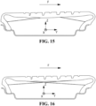
- each tire 10 and R' with a rolling surface was simulated when each tire 10 and R' is subjected to a given lateral force F, mounted on a nominal rim, inflated to a pressure equal to 250 kPa and under a load greater than the nominal load so as to simulate a load transfer equivalent to the load transfer that would be observed on a wheel exterior of a vehicle taking a turn.
- F lateral force
- the number of axial bending zones is less for tire 10 than for the control tire R'.
- the axial limits of each rib of the tread of the tire 10 have been represented by dotted lines in order to be able to compare the contact areas with each other.
- each rib of the tread of the tire 10 has a contact area width significantly greater than that of the corresponding rib of the tire R'.
- the fact that the portions 523 and 524 intersect in the toric cavity of the tire R' causes the appearance of several zones of axial bending of the tread and therefore a reduction in the axial width of the ribs in contact with the rolling ground, in particular due to a displacement of the axial edges of each rib radially in the space formed by the longitudinal grooves of the tread delimited by the axial edges of each rib.
- the tooling comprises a toroidal core 1000 having, around its main axis Z10, a convex external receiving surface 1000_out and which comprises a radially external summit zone 1100 intended to receive components constituting the summit 12, a first lateral zone 1200 folded towards the main axis Z10 of the core and intended to receive components constituting the first flank 30A and the first bead 32A and a second lateral zone 1300 folded towards the main axis Z10 of the core and intended to receive components constituting the second flank 30B and the second bead 32B.
- the core 1000 materializes a volume, called the reserved volume, which is delimited externally by the receiving surface 1000_out and which corresponds to the internal cavity 35.
- the core 1000 can thus occupy, and therefore temporarily reserve, during the manufacture of the tire, the volume whose shape and dimensions correspond to those of the internal cavity 35, a volume which will become the internal cavity 35.
- the core 1000 has a plurality of passages 1500 which extend inside the reserved volume, under the receiving surface 1000_out, and which open onto said receiving surface 1000_out such that each of said passages 1500 connects the top zone 1100 of the receiving surface 1000_out to one of the first and second lateral zones 1200, 1300 so that the core 10 can receive, inside said passages 1500, the stiffening elements 52.
- the grooves 1500 are blind and have a solid bottom 1900, located under the receiving surface 1000_out, in the reserved volume.
- the core 1000 comprises, as is notably visible on the figure 20A , an assembly of several annular subassemblies 2100, 2200, 2300 comprising: i) a first annular subassembly 2100 called central crown 2100, which forms a central portion of the summit zone 1100 of the receiving surface 1000_out intended to receive one or more components constituting the top 12, ii) a second annular subassembly 2200 called left ear 2200 containing the grooves 1500 forming the passages intended for the stiffening elements 52 which connect the first side 30A to the top 12, and iii) a third annular subassembly 2300 called right ear 2300 containing the grooves 1500 forming the passages intended for the stiffening elements 52 which connect the second side 30B to the top 12.
- Said annular subassemblies 2100, 2200, 2300 are each angularly divided into sectors 2400, 2500, 2600, 2700, 2800, 2900, in azimuth around the main axis Z10, according to an alternation of sectors called “keys” 2400, 2600, 2800, and sectors called “vaults” 2500, 2700, 2900, supported and blocked in position by the keys 2400, 2600, 2800, and designed to become maneuverable after they have been released by the withdrawal of the keys 2400, 2600, 2800.
- the central crown 2100 is subdivided into a plurality of crown keys 2400 and crown vaults. 2500.
- both the ear keys 2600, 2800 and the ear vaults 2700, 2900 will be made of a metal alloy, more preferably of an aluminum alloy.
- the method for manufacturing the tire 10 in practice amounts to using a tool as described above.
- the method comprises a preparation step (S0), during which the tool is prepared.
- the keys 2400 and arches 2500 will be assembled to form said central crown, as illustrated in the Figures 20A and 20B , then we will fix, on each of the draft faces 3200, 3300 a succession of ear keys 2600, 2800 and ear vaults 2700, 2900 to form the ears 2200, 2300.
- the method then comprises a step (S2) of placing the stiffening elements 52, during which the stiffening element 52 is passed through each passage 1500.
- the continuous stiffening element 52 is arranged in a boustrophedon fashion through the successive passages 1500, here by inserting the continuous stiffening element 52 into the grooves 1500 and by causing the continuous stiffening element 52 to emerge above the receiving surface 1000_out in the top zone 1100 and in the lateral zones 1200, 1300, at the radially inner anchoring points 54A, 54B and outer anchoring points 56A, 56B, as can be seen in the figure. figure 21 .
- the method comprises a protection step (S3), during which an anti-penetration device (not illustrated) is implemented which, during the filling step (S4) and during the baking step (S5), cooperates with the core 1000 to prevent penetration of the components constituting the crown 12, the sides 30A, 30B or the beads 32A, 32B into the grooves 1500 in which the stiffening elements 52 are engaged.
- an anti-penetration device may comprise elements for filling the grooves 1500 or even masking strips or shells that are placed on the grooves so as to cover the grooves 1500.
- the method then comprises a filling step (S4) during which the constituent components of the top 12, sidewalls 30A, 30B and beads 32A, 32B.
- Said components comprise strips or plies based on polymeric compositions and the wire reinforcement elements making it possible to form the different layers of the tire 10.
- the method then comprises a baking step (S5) during which the core 1000 and the blank of the tire 10 carried by said core 1000 are placed in a baking mold, in order to vulcanize the components.
- the method then comprises a demolding step (S6) during which the core 1000 is released from the tire 10, leaving the stiffening elements 52 in place in the internal cavity 35, as is illustrated in particular in the sequences of Figures 22A to 22F .
- the said parts are disassembled and gradually extracted to release the tire 10.
- the demolding step (S6) first comprises a first sub-step of removing the central crown 2100, during which the keys 2400 of the central crown are removed radially, then the arches 2500 of the central crown, in order to release the ears 2200, 2300, and so that we find our in a configuration in which the sectors 2600, 2700, 2800, 2900 of the ears 2200, 2300 are accessible from the inside of the tire 10 as illustrated in the figure.
- the extraction of the sectors 2600, 2700, 2800, 2900 is here carried out according to an axial translation extraction movement M_A, if the side walls of the grooves 1500 are generated by following an axial generating direction DG_A colinear with the main axis Z10, as illustrated in the figure 22B ; said axial translation extraction movement M_A may be followed by a tilting movement M_B in pitch around an axis normal to the sagittal meridian plane of the sector 2600, 2700, 2800, 2900 considered, as illustrated in the figures 22D, 22E .
- the extraction sequence can be completed freely from the inside of the tire 10, for example by following, as illustrated in the figure 22F , a radial movement which brings the sector 2600, 2700, 2800, 2900 concerned closer to the main axis Z10, to completely remove said sector from the tire 10.
- the anti-penetration device can be extracted in turn. For example, in the case of masking strips, the latter can be extracted by a spiral sliding which makes them pass into the space between two successive stiffening elements 52.
- said method comprises a pre-filling step (S1) during which, as illustrated in the figure 21 , the radially inner 60A, 60B and outer 70A, 70B reinforcement structures are placed on the lateral zones 1200, 1300 and on the top zone 1100 of the receiving surface 1000_out of the core 1000, opposite the radially inner 54A, 54B and outer 56A, 56B anchor points.
- the loops forming the portions 521, 522 will be captive to the radially inner 60A, 60B reinforcement structures and to the other adjacent components of the tire 10 placed on the lateral zones 1200, 1300, while the portions 525 will be captive to the radially outer 70A, 70B reinforcement structures and to the other adjacent components of the tire 10.
- a cavity noise absorber for example fixed to the tire mounting bracket or to the tire itself so as to reduce the cavity noise of the tire.
- noise absorbers are notably described in WO2018046376 , WO2013182477 , WO2011051203 , EP2660075 , EP1253025 , EP1876038 Or EP3406462 .
Landscapes
- Engineering & Computer Science (AREA)
- Mechanical Engineering (AREA)
- Tires In General (AREA)
Applications Claiming Priority (2)
| Application Number | Priority Date | Filing Date | Title |
|---|---|---|---|
| FR2102820A FR3120817B1 (fr) | 2021-03-22 | 2021-03-22 | Pneumatique comprenant une structure de rigidification endurante |
| PCT/FR2022/050488 WO2022200717A1 (fr) | 2021-03-22 | 2022-03-17 | Pneumatique comprenant une structure de rigidification endurante |
Publications (3)
| Publication Number | Publication Date |
|---|---|
| EP4308387A1 EP4308387A1 (fr) | 2024-01-24 |
| EP4308387B1 true EP4308387B1 (fr) | 2025-01-22 |
| EP4308387C0 EP4308387C0 (fr) | 2025-01-22 |
Family
ID=76034758
Family Applications (1)
| Application Number | Title | Priority Date | Filing Date |
|---|---|---|---|
| EP22714490.4A Active EP4308387B1 (fr) | 2021-03-22 | 2022-03-17 | Pneumatique comprenant une structure de rigidification endurante |
Country Status (6)
| Country | Link |
|---|---|
| US (1) | US12472775B2 (https=) |
| EP (1) | EP4308387B1 (https=) |
| JP (1) | JP2024510672A (https=) |
| CN (1) | CN117042983A (https=) |
| FR (1) | FR3120817B1 (https=) |
| WO (1) | WO2022200717A1 (https=) |
Families Citing this family (10)
| Publication number | Priority date | Publication date | Assignee | Title |
|---|---|---|---|---|
| FR3120815B1 (fr) | 2021-03-22 | 2023-02-24 | Michelin & Cie | Pneumatique comprenant une structure de rigidification endurante et permettant une bonne mise a plat |
| FR3120816B1 (fr) | 2021-03-22 | 2023-02-10 | Michelin & Cie | Pneumatique comprenant une decoupure circonferentielle et une structure de rigidification endurante et permettant une mise a plat optimisee |
| CN121263298A (zh) | 2023-04-26 | 2026-01-02 | 米其林集团总公司 | 包括具有不规则锚固的加强结构的轮胎 |
| FR3148162B1 (fr) * | 2023-04-26 | 2025-04-11 | Michelin & Cie | Noyau à rainures en chevrons pour la fabrication d’un bandage haubané |
| FR3157276B1 (fr) | 2023-12-26 | 2025-12-19 | Michelin & Cie | Pneumatique comprenant une structure de rigidification endurante et une éventuelle couche d’étanchéité interrompue |
| FR3157273B1 (fr) | 2023-12-26 | 2025-12-26 | Michelin & Cie | Pneumatique comprenant une structure de rigidification endurante et une interface entre des couches extérieure et intérieure |
| FR3157275B1 (fr) | 2023-12-26 | 2025-12-26 | Michelin & Cie | Pneumatique comprenant une structure de rigidification endurante comprenant des organes d’ancrage |
| FR3157274B1 (fr) | 2023-12-26 | 2025-12-26 | Michelin & Cie | Pneumatique comprenant une structure de rigidification endurante comprenant des points d’ancrage communs |
| FR3159347B1 (fr) | 2024-02-16 | 2026-03-06 | Michelin & Cie | Pneumatique comprenant une structure de rigidification endurante et un ancrage radialement intérieur performant |
| FR3164942A1 (fr) | 2024-07-24 | 2026-01-30 | Compagnie Generale Des Etablissements Michelin | Guide fil pour appareil de fabrication d’une structure de rigidification filaire d’un pneumatique, et appareil de fabrication associé |
Family Cites Families (24)
| Publication number | Priority date | Publication date | Assignee | Title |
|---|---|---|---|---|
| US3010504A (en) * | 1960-06-06 | 1961-11-28 | Gen Motors Corp | Tire construction |
| FR2638398A1 (fr) * | 1988-11-03 | 1990-05-04 | Lecal Roger | Pneumatique de roue a triangulation de maintien |
| GB2299554A (en) | 1995-04-06 | 1996-10-09 | Russell John Searle | Pneumatic tyres |
| DE60209053T2 (de) | 2001-04-16 | 2006-09-28 | Sumitomo Rubber Industries Ltd., Kobe | Reifengeräusch reduzierende Vorrichtung |
| WO2003106197A1 (fr) * | 2002-06-14 | 2003-12-24 | Societe De Technologie Michelin | Pneumatique avec nappe sommet imbriquee dans une nappe carcasse |
| JP2005254993A (ja) * | 2004-03-11 | 2005-09-22 | Bridgestone Corp | 空気入りラジアルタイヤ |
| US20050279438A1 (en) * | 2004-06-21 | 2005-12-22 | John Onracek | Motor vehicle tire |
| JP4330550B2 (ja) | 2005-04-28 | 2009-09-16 | 住友ゴム工業株式会社 | 空気入りタイヤとリムとの組立体 |
| FR2952645B1 (fr) | 2009-10-27 | 2011-12-16 | Michelin Soc Tech | Bandage pneumatique dont la paroi interne est pourvue d'une couche de caoutchouc thermo-expansible |
| FR2953762B1 (fr) * | 2009-12-14 | 2011-12-09 | Michelin Soc Tech | Pneumatique dont le sommet est pourvu d'une armature de rigidification. |
| WO2012090310A1 (ja) | 2010-12-28 | 2012-07-05 | ソシエテ ド テクノロジー ミシュラン | 空気入りタイヤ |
| FR2978770B1 (fr) | 2011-08-04 | 2013-09-27 | Michelin Soc Tech | Composition adhesive aqueuse a base de polyaldehyde et phloroglucinol |
| FR2991686B1 (fr) | 2012-06-08 | 2015-05-01 | Michelin & Cie | Bandage pneumatique dont la paroi interne est pourvue d'une couche de mousse polyurethane specifique |
| JP2015077922A (ja) * | 2013-10-18 | 2015-04-23 | 株式会社ブリヂストン | 安全タイヤ |
| DE102014018639B4 (de) * | 2014-12-13 | 2021-06-10 | Audi Ag | Fahrzeugrad, insbesondere Kraftfahrzeugrad |
| FR3038543B1 (fr) | 2015-07-06 | 2017-07-21 | Michelin & Cie | Dispositif de type pneumatique pour vehicule |
| FR3049610A1 (fr) | 2016-04-01 | 2017-10-06 | Michelin & Cie | Composition adhesive aqueuse comportant une resine thermodurcissable et un latex |
| FR3055580A1 (fr) | 2016-09-07 | 2018-03-09 | Compagnie Generale Des Etablissements Michelin | Pneumatique muni d'elements de sculpture asymetriques et d'amortisseurs de bruit decentres |
| JP6524341B2 (ja) | 2017-01-25 | 2019-06-05 | 住友ゴム工業株式会社 | 空気入りタイヤ |
| CN111163948A (zh) * | 2017-10-02 | 2020-05-15 | 米其林集团总公司 | 具有增强的下部区域的轮胎 |
| EP3724004B1 (fr) | 2017-12-11 | 2022-07-20 | Compagnie Generale Des Etablissements Michelin | Pneumatique pour vehicule avec structure de rigidification dans la cavite torique interieure |
| WO2020079366A1 (fr) | 2018-10-18 | 2020-04-23 | Compagnie Generale Des Etablissements Michelin | Pneumatique pour vehicule avec structure porteuse |
| FR3089869A3 (fr) | 2018-12-17 | 2020-06-19 | Michelin & Cie | Pneumatique pour véhicule comprenant une structure de rigidification. |
| FR3120816B1 (fr) | 2021-03-22 | 2023-02-10 | Michelin & Cie | Pneumatique comprenant une decoupure circonferentielle et une structure de rigidification endurante et permettant une mise a plat optimisee |
-
2021
- 2021-03-22 FR FR2102820A patent/FR3120817B1/fr active Active
-
2022
- 2022-03-17 JP JP2023557739A patent/JP2024510672A/ja active Pending
- 2022-03-17 EP EP22714490.4A patent/EP4308387B1/fr active Active
- 2022-03-17 WO PCT/FR2022/050488 patent/WO2022200717A1/fr not_active Ceased
- 2022-03-17 US US18/283,503 patent/US12472775B2/en active Active
- 2022-03-17 CN CN202280023072.0A patent/CN117042983A/zh active Pending
Also Published As
| Publication number | Publication date |
|---|---|
| WO2022200717A8 (fr) | 2022-11-03 |
| US20240174025A1 (en) | 2024-05-30 |
| EP4308387C0 (fr) | 2025-01-22 |
| JP2024510672A (ja) | 2024-03-08 |
| WO2022200717A1 (fr) | 2022-09-29 |
| CN117042983A (zh) | 2023-11-10 |
| FR3120817B1 (fr) | 2024-03-29 |
| US12472775B2 (en) | 2025-11-18 |
| FR3120817A1 (fr) | 2022-09-23 |
| EP4308387A1 (fr) | 2024-01-24 |
Similar Documents
| Publication | Publication Date | Title |
|---|---|---|
| EP4308387B1 (fr) | Pneumatique comprenant une structure de rigidification endurante | |
| EP3390114B1 (fr) | Ensemble pour pneumatique comprenant des tissu(s) ou tricot(s) imprégnés et un moyen de maintien sacrificiel | |
| EP3568290B1 (fr) | Assemblage comprenant un tissu partiellement rompable et une structure porteuse | |
| WO2018130782A1 (fr) | Assemblage comprenant une structure élastique et une structure porteuse | |
| WO2018130785A1 (fr) | Assemblage pour pneumatique comprenant une structure rompable et une structure porteuse | |
| EP3691919B1 (fr) | Pneumatique avec zone basse renforcee | |
| EP4313627B1 (fr) | Pneumatique comprenant une structure de rigidification endurante et permettant une bonne mise a plat | |
| EP4313628B1 (fr) | Pneumatique comprenant une découpure circonferentielle et une structure de rigidification endurante et permettant une mise a plat optimisée | |
| EP1523419B1 (fr) | Armature de bourrelet de pneumatique comprenant des renforts discontinus | |
| EP2794295B1 (fr) | Pneumatique comportant des cables d'armature de carcasse presentant une faible permeabilite, et des fils textiles associes a l'armature de carcasse | |
| EP3277867B1 (fr) | Procede de fabrication d'une structure de renfort pour pneumatique | |
| FR2977828A1 (fr) | Pneumatique pliable, procede de pliage et utilisation | |
| WO2017013576A1 (fr) | Pneumatique comprenant des éléments de renfort sous forme de bandelettes partiellement superposées | |
| WO2025172001A1 (fr) | Pneumatique comprenant une structure de rigidification endurante et un ancrage radialement intérieur performant | |
| WO2024224026A1 (fr) | Pneumatique comprenant une structure de rigidification à ancrage irrégulier | |
| EP4701843A1 (fr) | Pneumatique comprenant une structure de rigidification à ancrage irrégulier | |
| EP3880492B1 (fr) | Pneumatique pour véhicule à deux roues comprenant un renfort de frettage hybride | |
| EP4688461A1 (fr) | Armatures de carcasse de pneumatique pour avion | |
| FR3157274A1 (fr) | Pneumatique comprenant une structure de rigidification endurante comprenant des points d’ancrage communs | |
| FR3157276A1 (fr) | Pneumatique comprenant une structure de rigidification endurante et une éventuelle couche d’étanchéité interrompue | |
| EP4377101A1 (fr) | Pneumatique pour motocylcette a haute vitesse limite | |
| FR3153564A1 (fr) | Pneumatique | |
| FR3157275A1 (fr) | Pneumatique comprenant une structure de rigidification endurante comprenant des organes d’ancrage | |
| FR3112311A1 (fr) | Pneumatique pour véhicule de tourisme |
Legal Events
| Date | Code | Title | Description |
|---|---|---|---|
| STAA | Information on the status of an ep patent application or granted ep patent |
Free format text: STATUS: UNKNOWN |
|
| STAA | Information on the status of an ep patent application or granted ep patent |
Free format text: STATUS: THE INTERNATIONAL PUBLICATION HAS BEEN MADE |
|
| PUAI | Public reference made under article 153(3) epc to a published international application that has entered the european phase |
Free format text: ORIGINAL CODE: 0009012 |
|
| STAA | Information on the status of an ep patent application or granted ep patent |
Free format text: STATUS: REQUEST FOR EXAMINATION WAS MADE |
|
| 17P | Request for examination filed |
Effective date: 20231020 |
|
| AK | Designated contracting states |
Kind code of ref document: A1 Designated state(s): AL AT BE BG CH CY CZ DE DK EE ES FI FR GB GR HR HU IE IS IT LI LT LU LV MC MK MT NL NO PL PT RO RS SE SI SK SM TR |
|
| DAV | Request for validation of the european patent (deleted) | ||
| DAX | Request for extension of the european patent (deleted) | ||
| GRAP | Despatch of communication of intention to grant a patent |
Free format text: ORIGINAL CODE: EPIDOSNIGR1 |
|
| STAA | Information on the status of an ep patent application or granted ep patent |
Free format text: STATUS: GRANT OF PATENT IS INTENDED |
|
| INTG | Intention to grant announced |
Effective date: 20241010 |
|
| GRAS | Grant fee paid |
Free format text: ORIGINAL CODE: EPIDOSNIGR3 |
|
| GRAA | (expected) grant |
Free format text: ORIGINAL CODE: 0009210 |
|
| STAA | Information on the status of an ep patent application or granted ep patent |
Free format text: STATUS: THE PATENT HAS BEEN GRANTED |
|
| AK | Designated contracting states |
Kind code of ref document: B1 Designated state(s): AL AT BE BG CH CY CZ DE DK EE ES FI FR GB GR HR HU IE IS IT LI LT LU LV MC MK MT NL NO PL PT RO RS SE SI SK SM TR |
|
| REG | Reference to a national code |
Ref country code: GB Ref legal event code: FG4D Free format text: NOT ENGLISH |
|
| REG | Reference to a national code |
Ref country code: CH Ref legal event code: EP |
|
| REG | Reference to a national code |
Ref country code: IE Ref legal event code: FG4D Free format text: LANGUAGE OF EP DOCUMENT: FRENCH |
|
| REG | Reference to a national code |
Ref country code: DE Ref legal event code: R096 Ref document number: 602022009812 Country of ref document: DE |
|
| U01 | Request for unitary effect filed |
Effective date: 20250206 |
|
| U07 | Unitary effect registered |
Designated state(s): AT BE BG DE DK EE FI FR IT LT LU LV MT NL PT RO SE SI Effective date: 20250212 |
|
| U20 | Renewal fee for the european patent with unitary effect paid |
Year of fee payment: 4 Effective date: 20250325 |
|
| PG25 | Lapsed in a contracting state [announced via postgrant information from national office to epo] |
Ref country code: RS Free format text: LAPSE BECAUSE OF FAILURE TO SUBMIT A TRANSLATION OF THE DESCRIPTION OR TO PAY THE FEE WITHIN THE PRESCRIBED TIME-LIMIT Effective date: 20250422 |
|
| PG25 | Lapsed in a contracting state [announced via postgrant information from national office to epo] |
Ref country code: PL Free format text: LAPSE BECAUSE OF FAILURE TO SUBMIT A TRANSLATION OF THE DESCRIPTION OR TO PAY THE FEE WITHIN THE PRESCRIBED TIME-LIMIT Effective date: 20250122 |
|
| PG25 | Lapsed in a contracting state [announced via postgrant information from national office to epo] |
Ref country code: ES Free format text: LAPSE BECAUSE OF FAILURE TO SUBMIT A TRANSLATION OF THE DESCRIPTION OR TO PAY THE FEE WITHIN THE PRESCRIBED TIME-LIMIT Effective date: 20250122 |
|
| PG25 | Lapsed in a contracting state [announced via postgrant information from national office to epo] |
Ref country code: IS Free format text: LAPSE BECAUSE OF FAILURE TO SUBMIT A TRANSLATION OF THE DESCRIPTION OR TO PAY THE FEE WITHIN THE PRESCRIBED TIME-LIMIT Effective date: 20250522 Ref country code: NO Free format text: LAPSE BECAUSE OF FAILURE TO SUBMIT A TRANSLATION OF THE DESCRIPTION OR TO PAY THE FEE WITHIN THE PRESCRIBED TIME-LIMIT Effective date: 20250422 |
|
| PG25 | Lapsed in a contracting state [announced via postgrant information from national office to epo] |
Ref country code: HR Free format text: LAPSE BECAUSE OF FAILURE TO SUBMIT A TRANSLATION OF THE DESCRIPTION OR TO PAY THE FEE WITHIN THE PRESCRIBED TIME-LIMIT Effective date: 20250122 |
|
| PG25 | Lapsed in a contracting state [announced via postgrant information from national office to epo] |
Ref country code: GR Free format text: LAPSE BECAUSE OF FAILURE TO SUBMIT A TRANSLATION OF THE DESCRIPTION OR TO PAY THE FEE WITHIN THE PRESCRIBED TIME-LIMIT Effective date: 20250423 |
|
| PG25 | Lapsed in a contracting state [announced via postgrant information from national office to epo] |
Ref country code: SM Free format text: LAPSE BECAUSE OF FAILURE TO SUBMIT A TRANSLATION OF THE DESCRIPTION OR TO PAY THE FEE WITHIN THE PRESCRIBED TIME-LIMIT Effective date: 20250122 |
|
| PG25 | Lapsed in a contracting state [announced via postgrant information from national office to epo] |
Ref country code: MC Free format text: LAPSE BECAUSE OF FAILURE TO SUBMIT A TRANSLATION OF THE DESCRIPTION OR TO PAY THE FEE WITHIN THE PRESCRIBED TIME-LIMIT Effective date: 20250122 |
|
| PG25 | Lapsed in a contracting state [announced via postgrant information from national office to epo] |
Ref country code: CZ Free format text: LAPSE BECAUSE OF FAILURE TO SUBMIT A TRANSLATION OF THE DESCRIPTION OR TO PAY THE FEE WITHIN THE PRESCRIBED TIME-LIMIT Effective date: 20250122 |
|
| REG | Reference to a national code |
Ref country code: CH Ref legal event code: H13 Free format text: ST27 STATUS EVENT CODE: U-0-0-H10-H13 (AS PROVIDED BY THE NATIONAL OFFICE) Effective date: 20251023 |
|
| PG25 | Lapsed in a contracting state [announced via postgrant information from national office to epo] |
Ref country code: SK Free format text: LAPSE BECAUSE OF FAILURE TO SUBMIT A TRANSLATION OF THE DESCRIPTION OR TO PAY THE FEE WITHIN THE PRESCRIBED TIME-LIMIT Effective date: 20250122 |
|
| PLBE | No opposition filed within time limit |
Free format text: ORIGINAL CODE: 0009261 |
|
| STAA | Information on the status of an ep patent application or granted ep patent |
Free format text: STATUS: NO OPPOSITION FILED WITHIN TIME LIMIT |
|
| 26N | No opposition filed |
Effective date: 20251023 |
|
| PG25 | Lapsed in a contracting state [announced via postgrant information from national office to epo] |
Ref country code: CH Free format text: LAPSE BECAUSE OF NON-PAYMENT OF DUE FEES Effective date: 20250331 |
|
| PG25 | Lapsed in a contracting state [announced via postgrant information from national office to epo] |
Ref country code: IE Free format text: LAPSE BECAUSE OF NON-PAYMENT OF DUE FEES Effective date: 20250317 |
|
| PGFP | Annual fee paid to national office [announced via postgrant information from national office to epo] |
Ref country code: GB Payment date: 20260324 Year of fee payment: 5 |
|
| U20 | Renewal fee for the european patent with unitary effect paid |
Year of fee payment: 5 Effective date: 20260326 |