EP4307698A1 - Bildsensorstabilisierung - Google Patents
Bildsensorstabilisierung Download PDFInfo
- Publication number
- EP4307698A1 EP4307698A1 EP23176059.6A EP23176059A EP4307698A1 EP 4307698 A1 EP4307698 A1 EP 4307698A1 EP 23176059 A EP23176059 A EP 23176059A EP 4307698 A1 EP4307698 A1 EP 4307698A1
- Authority
- EP
- European Patent Office
- Prior art keywords
- actuator
- image sensor
- lower frame
- frame
- upper frame
- Prior art date
- Legal status (The legal status is an assumption and is not a legal conclusion. Google has not performed a legal analysis and makes no representation as to the accuracy of the status listed.)
- Pending
Links
Images


Classifications
-
- H—ELECTRICITY
- H04—ELECTRIC COMMUNICATION TECHNIQUE
- H04N—PICTORIAL COMMUNICATION, e.g. TELEVISION
- H04N23/00—Cameras or camera modules comprising electronic image sensors; Control thereof
- H04N23/60—Control of cameras or camera modules
- H04N23/68—Control of cameras or camera modules for stable pick-up of the scene, e.g. compensating for camera body vibrations
- H04N23/682—Vibration or motion blur correction
- H04N23/685—Vibration or motion blur correction performed by mechanical compensation
- H04N23/687—Vibration or motion blur correction performed by mechanical compensation by shifting the lens or sensor position
-
- H—ELECTRICITY
- H04—ELECTRIC COMMUNICATION TECHNIQUE
- H04N—PICTORIAL COMMUNICATION, e.g. TELEVISION
- H04N23/00—Cameras or camera modules comprising electronic image sensors; Control thereof
- H04N23/60—Control of cameras or camera modules
- H04N23/68—Control of cameras or camera modules for stable pick-up of the scene, e.g. compensating for camera body vibrations
- H04N23/682—Vibration or motion blur correction
- H04N23/685—Vibration or motion blur correction performed by mechanical compensation
-
- G—PHYSICS
- G02—OPTICS
- G02B—OPTICAL ELEMENTS, SYSTEMS OR APPARATUS
- G02B5/00—Optical elements other than lenses
- G02B5/20—Filters
- G02B5/208—Filters for use with infrared or ultraviolet radiation, e.g. for separating visible light from infrared and/or ultraviolet radiation
-
- G—PHYSICS
- G03—PHOTOGRAPHY; CINEMATOGRAPHY; ANALOGOUS TECHNIQUES USING WAVES OTHER THAN OPTICAL WAVES; ELECTROGRAPHY; HOLOGRAPHY
- G03B—APPARATUS OR ARRANGEMENTS FOR TAKING PHOTOGRAPHS OR FOR PROJECTING OR VIEWING THEM; APPARATUS OR ARRANGEMENTS EMPLOYING ANALOGOUS TECHNIQUES USING WAVES OTHER THAN OPTICAL WAVES; ACCESSORIES THEREFOR
- G03B11/00—Filters or other obturators specially adapted for photographic purposes
-
- H—ELECTRICITY
- H04—ELECTRIC COMMUNICATION TECHNIQUE
- H04N—PICTORIAL COMMUNICATION, e.g. TELEVISION
- H04N23/00—Cameras or camera modules comprising electronic image sensors; Control thereof
- H04N23/10—Cameras or camera modules comprising electronic image sensors; Control thereof for generating image signals from different wavelengths
- H04N23/11—Cameras or camera modules comprising electronic image sensors; Control thereof for generating image signals from different wavelengths for generating image signals from visible and infrared light wavelengths
-
- H—ELECTRICITY
- H04—ELECTRIC COMMUNICATION TECHNIQUE
- H04N—PICTORIAL COMMUNICATION, e.g. TELEVISION
- H04N23/00—Cameras or camera modules comprising electronic image sensors; Control thereof
- H04N23/50—Constructional details
- H04N23/54—Mounting of pick-up tubes, electronic image sensors, deviation or focusing coils
-
- G—PHYSICS
- G03—PHOTOGRAPHY; CINEMATOGRAPHY; ANALOGOUS TECHNIQUES USING WAVES OTHER THAN OPTICAL WAVES; ELECTROGRAPHY; HOLOGRAPHY
- G03B—APPARATUS OR ARRANGEMENTS FOR TAKING PHOTOGRAPHS OR FOR PROJECTING OR VIEWING THEM; APPARATUS OR ARRANGEMENTS EMPLOYING ANALOGOUS TECHNIQUES USING WAVES OTHER THAN OPTICAL WAVES; ACCESSORIES THEREFOR
- G03B13/00—Viewfinders; Focusing aids for cameras; Means for focusing for cameras; Autofocus systems for cameras
- G03B13/32—Means for focusing
- G03B13/34—Power focusing
- G03B13/36—Autofocus systems
-
- H—ELECTRICITY
- H04—ELECTRIC COMMUNICATION TECHNIQUE
- H04N—PICTORIAL COMMUNICATION, e.g. TELEVISION
- H04N23/00—Cameras or camera modules comprising electronic image sensors; Control thereof
- H04N23/60—Control of cameras or camera modules
- H04N23/68—Control of cameras or camera modules for stable pick-up of the scene, e.g. compensating for camera body vibrations
- H04N23/681—Motion detection
Definitions
- the electronic device may include a large-sized touch display for securing wide visibility and convenience of manipulation.
- the electronic device may include at least one camera module.
- the electronic device may include at least one camera module located on the display or around the display.
- the subject matter of the present disclosure relates to image sensor stabilization, including image sensor stabilization in camera modules and camera module drive methods.
- an image sensor stabilization such as in camera modules and camera module drive methods, includes performing horizontal and rotational movements of an image sensor within a small area so as to reduce tremor of the image sensor caused by shaking of the camera module.
- three dimensional movement can be achieved with a single-layered guide ball.
- the size of the camera module in certain cases, can have reduced overall size relative to camera modules using multiple guide balls for three-dimensional motion.
- image sensor stabilization includes securing an image sensor in place even when no power is applied to the image sensor stabilizer. For example, in a state where no power is applied to an actuator, an attractive force between a fixing magnet and a yoke can fix the image sensor on a certain position. Accordingly, in some implementations, damage to the image sensor caused by an arbitrary movement thereof may be prevented.
- an image sensor stabilizer that includes: a lower frame; an upper frame on the lower frame and supporting an image sensor; a first actuator and a second actuator between the lower frame and the upper frame and configured to drive the upper frame to move in a first direction relative to the lower frame; a third actuator between the lower frame and the upper frame and configured to drive the upper frame to move in a second direction relative to the lower frame, the second direction intersecting the first direction; and a guide ball between the lower frame and the upper frame.
- the first actuator and the second actuator may be spaced apart from each other in the second direction.
- an image sensor stabilizer that includes: a lower frame; an upper frame on the lower frame; a first actuator and a second actuator configured to drive the upper frame to move in a first direction relative to the lower frame; a third actuator and a fourth actuator configured to drive the upper frame to move in a second direction relative to the lower frame, the second direction intersecting the first direction; and a guide ball between the lower frame and the upper frame.
- the lower frame may provide a lower reception hole that receives the guide ball.
- the upper frame may provide an upper reception hole on the lower reception hole.
- Each of a first length in the first direction of the upper reception hole and a second length in the second direction of the upper reception hole may be greater than a diameter of the guide ball, such that the guide ball may be movable in each of the first direction and the second direction in the upper reception hole.
- a camera module stabilizer that includes: an image sensor; an image sensor stabilizer that drives the image sensor to move; and an auto-focus apparatus on the image sensor stabilizer.
- the image sensor stabilizer may include: a lower frame; an upper frame on the lower frame; a first actuator that drives the upper frame to move in a first direction relative to the lower frame; a second actuator that drives the upper frame to move in a second direction relative to the lower frame, the second direction intersecting the first direction; and a guide ball between the lower frame and the upper frame.
- a center of the first actuator may be spaced apart in the second direction from a center of the image sensor.
- subject matter of the present disclosure can be embodied in a camera module drive method that includes: using an image sensor stabilizer to drive an image sensor to horizontally move in a first direction; driving the image sensor to horizontally move in a second direction that intersecting the first direction; and driving the image sensor to rotationally move about an axis parallel to a third direction that intersects each of the first direction and the second direction.
- the image sensor stabilizer may include: a lower frame; an upper frame on the lower frame and supporting the image sensor; and a first actuator and a second actuator configured to drive the upper frame to move in the first direction relative to the lower frame.
- the first actuator and the second actuator may be spaced apart from each other in the second direction.
- the step of driving the image sensor to rotationally move about the axis parallel to the third direction may include supplying the first actuator and the second actuator with powers whose values are different from each other.
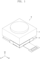
- FIG. 1 illustrates a perspective view showing an example of a camera module.
- symbol D1 indicates a first direction
- symbol D2 indicates a second direction that intersects and is substantially perpendicular to the first direction D 1
- symbol D3 indicates a third direction that intersects and is substantially perpendicular to each of the first direction D1 and the second direction D2.
- Each of the first and second directions D1 and D2 may be called a horizontal direction.
- the third direction D3 may be called a vertical direction.
- a camera module M is provided.
- the camera module M may indicate a certain device that generates an electric signal from an externally received optical signal.
- the camera module M may be used in combination with an electronic device.
- the camera module M may be used in combination with a smart-phone, a laptop computer, or so forth. A detailed description thereof will be further discussed below with reference to FIG. 17 .
- the camera module M may include an image sensor (see IMS of FIG. 3 ), an image sensor stabilizer B and an auto-focus apparatus A.
- the image sensor IMS may convert an optical signal into an electric signal.
- the image sensor IMS may include a charge coupled device (CCD) or CMOS image sensor (CIS).
- An electronic device may receive an electric signal converted in the image sensor IMS.
- the image sensor IMS will be further discussed in detail below.
- the image sensor stabilizer B may drive the image sensor IMS to move.
- the image sensor stabilizer B may drive the image sensor IMS to move in a direction parallel to a horizontal direction.
- the image sensor stabilizer B may drive the image sensor IMS to rotate about an axis parallel to the third direction D3.
- the image sensor stabilizer B may drive the image sensor IMS to move in a direction opposite to that in which the camera module M moves.
- the image sensor stabilizer B may be configured to move the image sensor IMS in a direction opposite to a movement direction of the camera module M so as to detect and compensate for the movement of the camera module M. It may thus be possible to correct a shake of the image sensor IMS.
- the image sensor stabilizer B may be an apparatus for optical image stabilization (OIS). The image sensor stabilizer B will be further discussed in detail below.
- the auto-focus apparatus A may be positioned on the image sensor stabilizer B.
- a lens may be disposed in the auto-focus apparatus A.
- the auto-focus apparatus A may vertically move the lens. Therefore, the auto-focus apparatus A may adjust a focus of the lens.
- the auto-focus apparatus A may include a drive mechanism configured to move the lens.
- FIG. 2 illustrates a perspective view showing an example of an image sensor stabilizer.
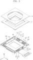
- FIG. 3 illustrates a partial exploded perspective view showing an example of an image sensor stabilizer.
- FIG. 4 illustrates a detailed exploded perspective view showing an example of an image sensor stabilizer.
- the image sensor stabilizer B includes a lower frame 1, an upper frame 3, an actuator, a fixing magnet 52, a guide ball BA, a yoke 7, and a cover 9.
- the lower frame 1 may be fixed to one side of a certain device.
- the lower frame 1 may be fixed on one side of an electronic device (see P of FIG. 17 ).
- the lower frame 1 may be positioned below the image sensor IMS. Alternatively, when viewed in plan, a portion of the lower frame 1 may surround the image sensor IMS.
- the lower frame 1 may provide a lower reception hole 113h. A portion of the guide ball BA may be inserted into the lower reception hole 113h.
- the lower frame 1 may include a ball guide structure 11 and a substrate 13.
- the ball guide structure 11 may include a ball guide body 111 and a reception block 113.
- the ball guide body 111 may have a rectangular frame shape.
- the reception block 113 may provide the lower reception hole 113h.
- the lower reception hole 113h may be provided in the reception block 113.
- the lower reception hole 113h may be an opening that is downwardly recessed to a certain depth from a top surface of the reception block 113.
- the reception block 113 may be provided in plural.
- four reception blocks 113 may be provided.
- the four reception blocks 113 may be disposed spaced apart from each other in the first direction D1 and the second direction D2.
- the lower reception hole 113h may also be provided in plural.
- a single reception block 113 and a single lower reception hole 113h will be discussed below.
- the substrate 13 may be coupled below the ball guide structure 11.
- the substrate 13 may include a substrate frame 131 and a connection substrate 133.
- the substrate frame 131 may have a rectangular frame shape.
- the substrate frame 131 may be associated with the ball guide structure 11.
- the substrate frame 131 may be combined with an inner surface of the ball guide structure 11.
- the substrate frame 131 may provide an extension reception hole 131h.
- the extension reception hole 131h may be positioned below the lower reception hole 113h.
- the extension reception hole 131h may be connected to the lower reception hole 113h.
- the extension reception hole 131h may vertically penetrate the substrate frame 131, but the present disclosure is not limited thereto.
- the connection substrate 133 may be connected to the substrate frame 131.
- the connection substrate 133 may include a printed circuit board (PCB).
- the ball guide structure 11 and the substrate 13 are separated components, but the present disclosure is not limited thereto.
- the ball guide structure 11 and the substrate 13 may be integrally formed into a single unitary piece.
- the substrate 13 may be omitted.
- the ball guide structure 11 may be omitted.
- the lower reception hole 113h may be provided in the substrate 13.
- the upper frame 3 may be positioned on the lower frame 1.
- the upper frame 3 may support the image sensor IMS.
- the upper frame 3 may be movable relative to the lower frame 1.
- the upper frame 3 may move in the first direction D1, e.g., parallel to the lower frame 1.
- the upper frame 3 may move in the second direction D2, e.g., parallel to the lower frame 1.
- the upper frame 3 may be rotationally movable relative to the lower frame 1.
- the image sensor IMS may be fixedly coupled to the upper frame 3. Therefore, the image sensor IMS may be movable together with the upper frame 3.
- the upper frame 3 may provide an upper reception hole (see upper reception hole 33h of FIG. 8 ). A portion of the guide ball BA may be inserted into the upper reception hole 33h.
- the upper frame 3 may include an upper frame body 31, a ball reception member 33, and an infrared ray color filter (IRCF) 35.
- IRCF infrared ray color filter
- the upper frame body 31 may have a rectangular frame shape.
- the upper frame body 31 may provide an upper central hole 31h.
- the upper central hole 31h may expose the image sensor IMS.
- the ball reception member 33 may be associated with the upper frame body 31.
- the ball reception member 33 may provide the upper reception hole 33h (see FIG. 8 ).
- the upper reception hole 33h may be provided in the ball reception member 33.
- the upper reception hole 33h may be an opening that is upwardly recessed from a bottom surface of the ball reception member 33.
- the upper reception hole 33h may be positioned above the lower reception hole 113h.
- multiple ball reception members 33 may be provided.
- four ball reception member 33 may be provided.
- the four ball reception members 33 may be spaced apart from each other in the first direction D1 and the second direction D2. In this case, multiple upper reception holes 33h may also be provided.
- a single ball reception member 33 and a single upper reception hole 33h will be discussed below in the interest of convenience
- the IRCF 35 may be associated with the upper frame body 31.
- the IRCF 35 may be disposed in the upper central hole 31h.
- the IRCF 35 may be disposed on the image sensor IMS.
- the IRCF 35 may filter an infrared ray.
- the IRCF 35 may filter an infrared ray introduced into the image sensor IMS.
- the actuator may drive the upper frame 3 to move.
- the actuator may drive the upper frame 3 in the first direction D1, e.g., parallel relative to the lower frame 1.
- the actuator may drive the upper frame 3 in the second direction D2, e.g., parallel relative to the lower frame 1.
- the actuator may drive the upper frame 3 to rotationally move relative to the lower frame 1.
- the actuator may be positioned, for example, between the upper frame 3 and the lower frame 1.
- the actuator may be a voice coil motor (VCM).
- the actuator may include a magnet and a coil.
- the magnet may be fixedly coupled to the upper frame 3.
- the magnet may be fixedly coupled to a bottom surface of the upper frame body 31.
- the coil may be fixedly coupled to the lower frame 1.
- the coil may be fixedly coupled to a top surface of the substrate frame 131.
- Multiple actuators may be provided. For example, there may be provided a first actuator 51, a second actuator 53, a third actuator 55, and a fourth actuator 57.
- the first actuator 51 may drive the upper frame 3 to move in the first direction D1 relative to the lower frame 1.
- the first actuator 51 may include a first magnet 511 and a first coil 513.
- the first magnet 511 may be fixedly coupled to the upper frame 3.
- the first coil 513 may be fixedly coupled to the lower frame 1.
- the first magnet 511 may be positioned on the first coil 513.
- the first magnet 511 may be movable relative to the first coil 513. For example, when a power is applied to the first coil 513, the first magnet 511 may move relative to the first coil 513. A detailed description thereof will be further discussed below.
- the second actuator 53 may drive the upper frame 3 to move in the first direction D1 relative to the lower frame 1.
- the second actuator 53 may include a second magnet 531 and a second coil 533.
- the second magnet 531 may be fixedly coupled to the upper frame 3.
- the second coil 533 may be fixedly coupled to the lower frame 1.
- the second magnet 531 may be positioned on the second coil 533.
- the second magnet 531 may be movable relative to the second coil 533. For example, when a power is applied to the second coil 533, the second magnet 531 may move relative to the second coil 533. A detailed description thereof will be further discussed below.
- the third actuator 55 may drive the upper frame 3 to move in the second direction D2 relative to the lower frame 1.
- the third actuator 55 may include a third magnet 551 and a third coil 553.
- the third magnet 551 may be fixedly coupled to the upper frame 3.
- the third coil 553 may be fixedly coupled to the lower frame 1.
- the third magnet 551 may be positioned on the third coil 553.
- the third magnet 551 may be movable relative to the third coil 553. For example, when a power is applied to the third coil 553, the third magnet 551 may move relative to the third coil 553. A detailed description thereof will be further discussed below.
- the fourth actuator 57 may drive the upper frame 3 to move in the second direction D2 relative to the lower frame 1.
- the fourth actuator 57 may include a fourth magnet 571 and a fourth coil 573.
- the fourth magnet 571 may be fixedly coupled to the upper frame 3.
- the fourth coil 573 may be fixedly coupled to the lower frame 1.
- the fourth magnet 571 may be positioned on the fourth coil 573.
- the fourth magnet 571 may be movable relative to the fourth coil 573. For example, when a power is applied to the fourth coil 573, the fourth magnet 571 may move relative to the fourth coil 573. A detailed description thereof will be further discussed below.
- the fixing magnet 52 may be positioned between the upper frame 3 and the lower frame 1.
- the fixing magnet 52 may be coupled to the bottom surface of the upper frame body 31.
- the fixing magnet 52 may be provided in plural.
- the fixing magnet 52 and the yoke 7 can cause an electromagnetic field that generates an attractive force between the fixing magnet 52 and the yoke 7. Therefore, at the time when no actuator operates, the attractive force between the fixing magnet 52 and the yoke 7 may rigidly place the upper frame 3 on a certain position on the lower frame 1.
- the guide ball BA may be positioned between the upper frame 3 and the lower frame 1. A portion of the guide ball BA may be inserted into the upper reception hole 33h. Another portion of the guide ball BA may be inserted into the lower reception hole 113h. When the upper frame 3 moves relative to the lower frame 1, the guide ball BA may limit a range of movement of the upper frame 3.
- Multiple guide balls BA may be provided. For example, as shown in FIG. 4 , four guide balls BA may be provided.
- the four guide balls BA may be disposed spaced apart from each other in the first direction D1 and the second direction D2.
- the four guide balls BA can be coplanar in a single layer, e.g., at a same height along the third direction D3, between the lower and upper frame.
- the example of a single guide ball BA will be discussed in the interest of convenience, but the description set forth herein can be applied to other guide balls BA as well.
- the guide ball BA will be further described in detail below.
- the yoke 7 may support the lower frame 1.
- the yoke 7 may be coupled below the lower frame 1.
- the yoke 7 may include or comprise (for example, be made of) metal (for example, magnetic metals such as iron, nickel or cobalt and alloys thereof). Therefore, an attractive force may be generated between the yoke 7 and the fixing magnet 52.
- the yoke 7 may provide a yoke hole 7h.
- the cover 9 may be positioned on the upper frame 3.
- the cover 9 may protect the upper frame 3.
- the cover 9 may provide a cover hole 9h.
- the cover hole 9h may expose the image sensor IMS.
- the image sensor IMS may include a sensor chip SC and a sensor substrate G.
- the sensor chip SC may include a charge coupled device (CCD) or CMOS image sensor (CIS).
- the sensor substrate G may support the sensor chip SC. When viewed in plan, the sensor substrate G may surround the sensor chip SC.
- FIG. 5 illustrates a plan view showing an example of an image sensor stabilizer.
- FIG. 6 illustrates an enlarged plan view showing section X of FIG. 5 .
- FIG. 7 illustrates a cross-sectional view taken along line I-I' of FIG. 2 .
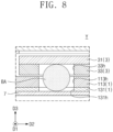
- FIG. 8 illustrates an enlarged cross-sectional view showing section Y of FIG. 7 .
- a center C2 of the first actuator 51 may be spaced apart in the second direction D2 from a center C1 of the image sensor IMS.
- an axis AX2 in the first direction D1 of the first actuator 51 is spaced apart at a certain distance d from an axis AX1 in the first direction D1 of the image sensor IMS. Therefore, when the first actuator 51 pushes the upper frame 3 in the first direction D1, a rotational moment may occur in the upper frame 3. A detailed description thereof will be further discussed below.
- the first actuator 51 and the second actuator 53 may be disposed spaced apart from each other in the second direction D2.
- the third actuator 55 may be spaced apart in the first direction D1 from each of the first actuator 51 and the second actuator 53.
- the third actuator 55 and the fourth actuator 57 may be disposed spaced apart from each other in the first direction D1.
- the upper reception hole 33h and the lower reception hole 113h overlap each other when viewed in plan.
- the guide ball BA may be inserted into the upper reception hole 33h and/or the lower reception hole 113h.
- a first length L1 indicates a length in the first direction D1 of the upper reception hole 33h.
- the first length L1 may range from about 1.0 mm to about 1.6 mm.
- the first length L1 may be about 1.3 mm.
- a second length L2 indicates a length in the second direction D2 of the upper reception hole 33h.
- the second length L2 may range from about 1.0 mm to about 1.6 mm.
- the second length L2 may be about 1.3 mm.
- the second length L2 may be substantially the same as the first length L1.
- the upper reception hole 33h may have a square shape when viewed in plan. The present disclosure, however, is not limited thereto.
- the upper reception hole 33h and lower reception hole 113h have a planar area, e.g., a circle with diameter d, if either of the upper reception hole 33h or lower reception hole 113 is a sphere with diameter d.
- the upper reception hole 33h may have a planar area substantially the same as or similar to that of the lower reception hole 113h. The present disclosure, however, is not limited thereto.
- the guide ball BA may have a diameter L3 less than the first length L1. Therefore, the guide ball BA may be movable in the first direction D1 in the upper reception hole 33h.
- the diameter L3 of the guide ball BA may be less than the second length L2. Therefore, the guide ball BA may be movable in the second direction D2 in the upper reception hole 33h.
- the first length L1 may be about 1.1 times to about 1.5 times the diameter L3 of the guide ball BA.
- the first length L1 may be about 1.3 times the diameter L3 of the guide ball BA.
- the present disclosure is not limited thereto.
- "about” or “substantially” can refer to a range of values slightly above or below the indicated amount, e.g., a range spanning 10% more or less than the indicated amount, 5% more or less than the indicated amount, or 1% more or less than the indicated amount.
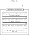
- FIG. 9 illustrates an example of a flow chart showing a camera module drive method S.
- the camera module drive method S may be a way of driving the camera module (see M of FIG. 1 ) discussed with reference to FIGS. 1 to 8 .
- the camera module drive method S includes driving an image sensor to horizontally move in a first direction (S1), driving the image sensor to horizontally move in a second direction (S2), driving the image sensor to rotationally move (S3), and driving the image sensor to fix on a certain position (S4).
- the camera module drive method S of FIG. 9 will be further discussed in detail below with reference to FIGS. 10 to 16 .
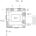
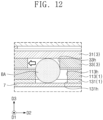
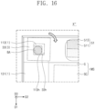
- FIGS. 10 to 12 illustrate plan and cross-sectional views showing an example of a procedure of horizontally moving an image sensor.
- the horizontal movement in the second direction (S2) may be performed by using the third actuator 55 and/or the fourth actuator 57.
- the third actuator 55 may push the ball reception member 33 in the second direction D2 and/or a direction opposite to the second direction D2.
- the third magnet 551 may move, on the third coil 553, in the second direction D2 and/or the direction opposite to the second direction D2. Therefore, the upper frame 3 may move, relative to the lower frame 1, in the second direction D2 and/or the direction opposite to the second direction D2.
- the first actuator 51 and/or the second actuator 53 may apply a force so that the ball reception member 33 may not move in the first direction D1.
- the movement of the upper frame 3 may be limited by the guide ball BA.
- the guide ball BA For example, as shown in FIGS. 11 and 12 , when one side of the guide ball BA contacts an inner surface that defines the upper reception hole 33h and/or the lower reception hole 113h, the movement of the upper frame 3 may be terminated.
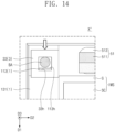
- FIGS. 13 and 14 illustrate plan views showing an example of procedure of horizontally moving an image sensor.
- the horizontal movement in the first direction (S1) may be performed by using the first actuator 51 and/or the second actuator 53.
- the first actuator 51 may push the ball reception member 33 in the first direction D1 and/or a direction opposite to the first direction D1.
- the first magnet 511 may move, on the first coil 513, in the first direction D1 and/or the direction opposite to the first direction D1. Therefore, the upper frame 3 may move, relative to the lower frame 1, in the first direction D1 and/or the direction opposite to the first direction D1.
- the third actuator 55 and/or the fourth actuator 57 may apply a force so that the ball reception member 33 may not move in the second direction D2.
- the movement of the upper frame 3 may be limited by the guide ball BA.
- the guide ball BA For example, as shown in FIG. 14 , when one side of the guide ball BA contacts an inner surface that defines the upper reception hole 33h and/or the lower reception hole 113h, the movement of the upper frame 3 may be terminated.
- FIGS. 15 and 16 illustrate plan views showing an example of a procedure of rotationally moving an image sensor.
- the rotational movement (S3) may include supplying the first actuator 51 and the second actuator 53 with powers whose values are different from each other.
- a power applied to the second actuator 53 may be greater than that applied to the first actuator 51.
- a power applied to the fourth actuator 57 may be greater than that applied to the third actuator 55.
- the upper frame 3 may rotationally move relative to the lower frame 1.
- the upper frame 2 may rotationally move, relative to the lower frame 1, about an axis parallel to the third direction D3.
- the upper frame 3 may rotate about the center C1 of the image sensor IMS.
- the rotation of the upper frame 3 may drive the image sensor IMS to rotate.
- the fixation of the image sensor (S4) may include allowing the attractive force between the yoke 7 and the fixing magnet 52 to rigidly place the upper frame 3 on a specific location on the yoke 7.
- the attractive force between the yoke 7 and the fixing magnet 52 may fix or place the upper frame 3 on a specific location on the yoke 7.
- FIG. 17 illustrates a plan view showing an example of an electronic device to which is applied a camera module.
- the camera module M may be applied to an electronic device P.
- the electronic device P may be, for example, a smart-phone.
- the camera module M is associated with a housing PB.
- the present disclosure is not limited thereto, and the camera module M may be applied to other electronic devices.
- an image sensor stabilizer, a camera module including the same, and a camera module drive method can drive an image sensor to rotate.
- the direction of driving the image sensor can be horizontal or other directions. Consequently, even when the camera module shakes, a tremor of the image sensor can be reduced.
- an image sensor stabilizer, a camera module including the same, and a camera module drive method three types of movement may be achieved with only a single-layered guide ball.
- multiple types of guide balls may not be needed to accomplish three moving actions.
- the camera module can have a smaller volume compared to a camera module with multiple types of guide balls.
- an image sensor stabilizer, a camera module including the same, and a camera module drive method can secure an image sensor in place even when no power is applied to the image sensor stabilizer. For example, in a state where no power is applied to an actuator, an attractive force between a fixing magnet and a yoke may be used to fix the image sensor on a certain position. Accordingly, in some implementations, damage to the image sensor caused by an arbitrary movement thereof may be prevented.
- an image sensor stabilizer, a camera module including the same, and a camera module drive method can drive an image sensor to rotate.
- an image sensor stabilizer of relatively small volume and a camera module including the same, may be sufficient to achieve horizontal and rotational movements.
- an image sensor stabilizer, a camera module including the same, and a camera module drive method can fix an image sensor on or at a certain position even when no power is applied.
Landscapes
- Engineering & Computer Science (AREA)
- Multimedia (AREA)
- Signal Processing (AREA)
- Physics & Mathematics (AREA)
- General Physics & Mathematics (AREA)
- Health & Medical Sciences (AREA)
- Toxicology (AREA)
- Optics & Photonics (AREA)
- Studio Devices (AREA)
- Adjustment Of Camera Lenses (AREA)
Applications Claiming Priority (2)
| Application Number | Priority Date | Filing Date | Title |
|---|---|---|---|
| KR20220086491 | 2022-07-13 | ||
| KR1020220137544A KR20240009316A (ko) | 2022-07-13 | 2022-10-24 | 이미지 센서 스태빌라이져, 이를 포함하는 카메라 모듈 및 카메라 모듈 구동 방법 |
Publications (1)
| Publication Number | Publication Date |
|---|---|
| EP4307698A1 true EP4307698A1 (de) | 2024-01-17 |
Family
ID=86609572
Family Applications (1)
| Application Number | Title | Priority Date | Filing Date |
|---|---|---|---|
| EP23176059.6A Pending EP4307698A1 (de) | 2022-07-13 | 2023-05-30 | Bildsensorstabilisierung |
Country Status (3)
| Country | Link |
|---|---|
| US (1) | US12363435B2 (de) |
| EP (1) | EP4307698A1 (de) |
| JP (1) | JP2024012095A (de) |
Citations (3)
| Publication number | Priority date | Publication date | Assignee | Title |
|---|---|---|---|---|
| US20120025633A1 (en) * | 2010-07-30 | 2012-02-02 | Lg Innotek Co., Ltd. | Voice Coil Motor |
| US20170244899A1 (en) * | 2016-02-19 | 2017-08-24 | Canon Kabushiki Kaisha | Driving device provided in image stabilizer, control method therefor, and image pickup apparatus |
| US10310290B2 (en) * | 2015-10-20 | 2019-06-04 | Samsung Electronics Co., Ltd. | Camera module having stabilizer and electronic device including the same |
Family Cites Families (12)
| Publication number | Priority date | Publication date | Assignee | Title |
|---|---|---|---|---|
| JP2015099361A (ja) * | 2013-10-17 | 2015-05-28 | Hoya株式会社 | 撮像装置 |
| CN107533272B (zh) | 2015-06-24 | 2020-09-11 | 核心光电有限公司 | 折叠式镜头相机的低剖面三轴致动器 |
| KR102348365B1 (ko) | 2016-05-03 | 2022-01-10 | 삼성전자주식회사 | 카메라 모듈을 포함하는 전자 장치 |
| KR102507615B1 (ko) | 2016-12-16 | 2023-03-09 | 허친슨 테크놀로지 인코포레이티드 | 광학 이미지 안정화 서스펜션에서의 센서 이동 구조 |
| US10863094B2 (en) | 2017-07-17 | 2020-12-08 | Apple Inc. | Camera with image sensor shifting |
| EP4633183A3 (de) * | 2018-06-29 | 2025-12-24 | LG Innotek Co., Ltd. | Kameravorrichtung und optisches instrument |
| US11333951B2 (en) | 2019-04-22 | 2022-05-17 | Jahwa Electronics Co., Ltd. | Actuator for camera |
| KR20210061096A (ko) | 2019-11-19 | 2021-05-27 | 자화전자(주) | 카메라 렌즈 모듈 구동기구 |
| KR102297487B1 (ko) | 2019-12-26 | 2021-09-03 | (주)아이엠 | 광학식 손떨림 방지 기능을 구비한 액추에이터 모듈 |
| KR102416241B1 (ko) * | 2020-09-11 | 2022-07-06 | 주식회사 나무가 | 카메라 모듈 |
| US11575835B2 (en) | 2020-09-24 | 2023-02-07 | Apple Inc. | Multi-axis image sensor shifting system |
| US11750924B2 (en) | 2020-09-25 | 2023-09-05 | Apple Inc. | Camera with sensor-shifting autofocus mechanism |
-
2023
- 2023-04-06 US US18/296,904 patent/US12363435B2/en active Active
- 2023-05-30 EP EP23176059.6A patent/EP4307698A1/de active Pending
- 2023-06-02 JP JP2023091868A patent/JP2024012095A/ja active Pending
Patent Citations (3)
| Publication number | Priority date | Publication date | Assignee | Title |
|---|---|---|---|---|
| US20120025633A1 (en) * | 2010-07-30 | 2012-02-02 | Lg Innotek Co., Ltd. | Voice Coil Motor |
| US10310290B2 (en) * | 2015-10-20 | 2019-06-04 | Samsung Electronics Co., Ltd. | Camera module having stabilizer and electronic device including the same |
| US20170244899A1 (en) * | 2016-02-19 | 2017-08-24 | Canon Kabushiki Kaisha | Driving device provided in image stabilizer, control method therefor, and image pickup apparatus |
Also Published As
| Publication number | Publication date |
|---|---|
| JP2024012095A (ja) | 2024-01-25 |
| US12363435B2 (en) | 2025-07-15 |
| US20240022817A1 (en) | 2024-01-18 |
Similar Documents
| Publication | Publication Date | Title |
|---|---|---|
| US12210168B2 (en) | Lens driving apparatus having three ball members and opening in frame | |
| EP3849167B1 (de) | Kameramodul | |
| US9298017B2 (en) | Lens driving device | |
| US9835872B2 (en) | Lens holder driving device | |
| US10097760B2 (en) | Lens drive apparatus, camera module and camera | |
| KR101555904B1 (ko) | 카메라 모듈 | |
| KR101600574B1 (ko) | 카메라 모듈 | |
| JP2019113638A (ja) | レンズ駆動装置 | |
| CN111562682A (zh) | 相机模块 | |
| TWI761058B (zh) | 鏡頭驅動模組、攝像鏡頭與電子裝置 | |
| CN119668005A (zh) | 相机致动器 | |
| TW202336518A (zh) | 光學影像穩定驅動裝置、相機模組與電子裝置 | |
| JP2023540864A (ja) | レンズ駆動装置、カメラモジュール及び光学機器 | |
| US20240406527A1 (en) | Camera Arrangements with Mounted Image Sensors | |
| CN114257725B (zh) | 摄像结构 | |
| EP4307698A1 (de) | Bildsensorstabilisierung | |
| CN118984964A (zh) | 透镜驱动装置和相机设备 | |
| CN120092197A (zh) | 透镜驱动装置、相机装置和光学设备 | |
| CN117412172A (zh) | 图像传感器稳定器和包括该图像传感器稳定器的相机模块 | |
| EP4582846A1 (de) | Linsenantriebsvorrichtung, kameramodul und optisches instrument | |
| KR20240009316A (ko) | 이미지 센서 스태빌라이져, 이를 포함하는 카메라 모듈 및 카메라 모듈 구동 방법 | |
| EP4597189A1 (de) | Linsenantriebsvorrichtung, kameravorrichtung und optische vorrichtung | |
| CN118525235A (zh) | 透镜驱动装置和相机设备 | |
| JP2025524061A (ja) | レンズ駆動装置、カメラ装置及び光学機器 | |
| JP2025533763A (ja) | レンズ駆動装置、カメラ装置および光学機器 |
Legal Events
| Date | Code | Title | Description |
|---|---|---|---|
| PUAI | Public reference made under article 153(3) epc to a published international application that has entered the european phase |
Free format text: ORIGINAL CODE: 0009012 |
|
| STAA | Information on the status of an ep patent application or granted ep patent |
Free format text: STATUS: THE APPLICATION HAS BEEN PUBLISHED |
|
| AK | Designated contracting states |
Kind code of ref document: A1 Designated state(s): AL AT BE BG CH CY CZ DE DK EE ES FI FR GB GR HR HU IE IS IT LI LT LU LV MC ME MK MT NL NO PL PT RO RS SE SI SK SM TR |
|
| STAA | Information on the status of an ep patent application or granted ep patent |
Free format text: STATUS: REQUEST FOR EXAMINATION WAS MADE |
|
| 17P | Request for examination filed |
Effective date: 20240319 |
|
| RBV | Designated contracting states (corrected) |
Designated state(s): AL AT BE BG CH CY CZ DE DK EE ES FI FR GB GR HR HU IE IS IT LI LT LU LV MC ME MK MT NL NO PL PT RO RS SE SI SK SM TR |
|
| P01 | Opt-out of the competence of the unified patent court (upc) registered |
Free format text: CASE NUMBER: APP_34463/2024 Effective date: 20240607 |
|
| STAA | Information on the status of an ep patent application or granted ep patent |
Free format text: STATUS: EXAMINATION IS IN PROGRESS |
|
| 17Q | First examination report despatched |
Effective date: 20250709 |