EP4307507A1 - Electric power device, and control method for same - Google Patents
Electric power device, and control method for same Download PDFInfo
- Publication number
- EP4307507A1 EP4307507A1 EP22767187.2A EP22767187A EP4307507A1 EP 4307507 A1 EP4307507 A1 EP 4307507A1 EP 22767187 A EP22767187 A EP 22767187A EP 4307507 A1 EP4307507 A1 EP 4307507A1
- Authority
- EP
- European Patent Office
- Prior art keywords
- circuit
- attachment portion
- battery
- power storage
- attachment
- Prior art date
- Legal status (The legal status is an assumption and is not a legal conclusion. Google has not performed a legal analysis and makes no representation as to the accuracy of the status listed.)
- Pending
Links
Images







Classifications
-
- H—ELECTRICITY
- H02—GENERATION; CONVERSION OR DISTRIBUTION OF ELECTRIC POWER
- H02J—ELECTRIC POWER NETWORKS; CIRCUIT ARRANGEMENTS OR SYSTEMS FOR SUPPLYING OR DISTRIBUTING ELECTRIC POWER; SYSTEMS FOR STORING ELECTRIC ENERGY
- H02J7/00—Circuit arrangements for charging or discharging batteries or for supplying loads from batteries
- H02J7/90—Regulation of charging or discharging current or voltage
- H02J7/94—Regulation of charging or discharging current or voltage in response to battery current
-
- H—ELECTRICITY
- H02—GENERATION; CONVERSION OR DISTRIBUTION OF ELECTRIC POWER
- H02H—EMERGENCY PROTECTIVE CIRCUIT ARRANGEMENTS
- H02H5/00—Emergency protective circuit arrangements for automatic disconnection directly responsive to an undesired change from normal non-electric working conditions with or without subsequent reconnection
- H02H5/04—Emergency protective circuit arrangements for automatic disconnection directly responsive to an undesired change from normal non-electric working conditions with or without subsequent reconnection responsive to abnormal temperature
- H02H5/041—Emergency protective circuit arrangements for automatic disconnection directly responsive to an undesired change from normal non-electric working conditions with or without subsequent reconnection responsive to abnormal temperature additionally responsive to excess current
-
- H—ELECTRICITY
- H02—GENERATION; CONVERSION OR DISTRIBUTION OF ELECTRIC POWER
- H02H—EMERGENCY PROTECTIVE CIRCUIT ARRANGEMENTS
- H02H7/00—Emergency protective circuit arrangements specially adapted for specific types of electric machines or apparatus or for sectionalised protection of cable or line systems, and effecting automatic switching in the event of an undesired change from normal working conditions
- H02H7/18—Emergency protective circuit arrangements specially adapted for specific types of electric machines or apparatus or for sectionalised protection of cable or line systems, and effecting automatic switching in the event of an undesired change from normal working conditions for batteries; for accumulators
-
- H—ELECTRICITY
- H02—GENERATION; CONVERSION OR DISTRIBUTION OF ELECTRIC POWER
- H02J—ELECTRIC POWER NETWORKS; CIRCUIT ARRANGEMENTS OR SYSTEMS FOR SUPPLYING OR DISTRIBUTING ELECTRIC POWER; SYSTEMS FOR STORING ELECTRIC ENERGY
- H02J7/00—Circuit arrangements for charging or discharging batteries or for supplying loads from batteries
- H02J7/50—Circuit arrangements for charging or discharging batteries or for supplying loads from batteries acting upon multiple batteries simultaneously or sequentially
- H02J7/52—Circuit arrangements for charging or discharging batteries or for supplying loads from batteries acting upon multiple batteries simultaneously or sequentially for charge balancing, e.g. equalisation of charge between batteries
- H02J7/54—Passive balancing, e.g. using resistors or parallel MOSFETs
-
- H—ELECTRICITY
- H02—GENERATION; CONVERSION OR DISTRIBUTION OF ELECTRIC POWER
- H02J—ELECTRIC POWER NETWORKS; CIRCUIT ARRANGEMENTS OR SYSTEMS FOR SUPPLYING OR DISTRIBUTING ELECTRIC POWER; SYSTEMS FOR STORING ELECTRIC ENERGY
- H02J7/00—Circuit arrangements for charging or discharging batteries or for supplying loads from batteries
- H02J7/60—Circuit arrangements for charging or discharging batteries or for supplying loads from batteries including safety or protection arrangements
- H02J7/62—Circuit arrangements for charging or discharging batteries or for supplying loads from batteries including safety or protection arrangements against overcurrent
-
- H—ELECTRICITY
- H02—GENERATION; CONVERSION OR DISTRIBUTION OF ELECTRIC POWER
- H02J—ELECTRIC POWER NETWORKS; CIRCUIT ARRANGEMENTS OR SYSTEMS FOR SUPPLYING OR DISTRIBUTING ELECTRIC POWER; SYSTEMS FOR STORING ELECTRIC ENERGY
- H02J7/00—Circuit arrangements for charging or discharging batteries or for supplying loads from batteries
- H02J7/60—Circuit arrangements for charging or discharging batteries or for supplying loads from batteries including safety or protection arrangements
- H02J7/663—Circuit arrangements for charging or discharging batteries or for supplying loads from batteries including safety or protection arrangements using battery or load disconnect circuits
-
- H—ELECTRICITY
- H02—GENERATION; CONVERSION OR DISTRIBUTION OF ELECTRIC POWER
- H02J—ELECTRIC POWER NETWORKS; CIRCUIT ARRANGEMENTS OR SYSTEMS FOR SUPPLYING OR DISTRIBUTING ELECTRIC POWER; SYSTEMS FOR STORING ELECTRIC ENERGY
- H02J7/00—Circuit arrangements for charging or discharging batteries or for supplying loads from batteries
- H02J7/80—Circuit arrangements for charging or discharging batteries or for supplying loads from batteries including monitoring or indicating arrangements
-
- H—ELECTRICITY
- H02—GENERATION; CONVERSION OR DISTRIBUTION OF ELECTRIC POWER
- H02J—ELECTRIC POWER NETWORKS; CIRCUIT ARRANGEMENTS OR SYSTEMS FOR SUPPLYING OR DISTRIBUTING ELECTRIC POWER; SYSTEMS FOR STORING ELECTRIC ENERGY
- H02J7/00—Circuit arrangements for charging or discharging batteries or for supplying loads from batteries
- H02J7/80—Circuit arrangements for charging or discharging batteries or for supplying loads from batteries including monitoring or indicating arrangements
- H02J7/82—Control of state of charge [SOC]
-
- H—ELECTRICITY
- H02—GENERATION; CONVERSION OR DISTRIBUTION OF ELECTRIC POWER
- H02J—ELECTRIC POWER NETWORKS; CIRCUIT ARRANGEMENTS OR SYSTEMS FOR SUPPLYING OR DISTRIBUTING ELECTRIC POWER; SYSTEMS FOR STORING ELECTRIC ENERGY
- H02J7/00—Circuit arrangements for charging or discharging batteries or for supplying loads from batteries
- H02J7/90—Regulation of charging or discharging current or voltage
- H02J7/96—Regulation of charging or discharging current or voltage in response to battery voltage
- H02J7/965—Regulation of charging or discharging current or voltage in response to battery voltage obtained with the battery disconnected from the charge or discharge circuit
-
- H—ELECTRICITY
- H02—GENERATION; CONVERSION OR DISTRIBUTION OF ELECTRIC POWER
- H02J—ELECTRIC POWER NETWORKS; CIRCUIT ARRANGEMENTS OR SYSTEMS FOR SUPPLYING OR DISTRIBUTING ELECTRIC POWER; SYSTEMS FOR STORING ELECTRIC ENERGY
- H02J7/00—Circuit arrangements for charging or discharging batteries or for supplying loads from batteries
- H02J7/70—Circuit arrangements for charging or discharging batteries or for supplying loads from batteries characterised by the mechanical construction
- H02J7/751—Circuit arrangements for charging or discharging batteries or for supplying loads from batteries characterised by the mechanical construction concerning the insertion or the connection of the batteries
-
- Y—GENERAL TAGGING OF NEW TECHNOLOGICAL DEVELOPMENTS; GENERAL TAGGING OF CROSS-SECTIONAL TECHNOLOGIES SPANNING OVER SEVERAL SECTIONS OF THE IPC; TECHNICAL SUBJECTS COVERED BY FORMER USPC CROSS-REFERENCE ART COLLECTIONS [XRACs] AND DIGESTS
- Y02—TECHNOLOGIES OR APPLICATIONS FOR MITIGATION OR ADAPTATION AGAINST CLIMATE CHANGE
- Y02E—REDUCTION OF GREENHOUSE GAS [GHG] EMISSIONS, RELATED TO ENERGY GENERATION, TRANSMISSION OR DISTRIBUTION
- Y02E60/00—Enabling technologies; Technologies with a potential or indirect contribution to GHG emissions mitigation
- Y02E60/10—Energy storage using batteries
Definitions
- the present invention relates to an electric power device and a control method thereof.
- WO 2020/027202 A1 discloses a charging station that a battery can be attached to and detached from.
- the weight of the battery is a weight that can be carried by a person.
- the size of the battery is a size that can be carried by a person.
- the battery is attached in a slot of the charging station. When the battery is attached in the slot, the charging station can supply power to power equipment of a customer.
- the charging station is provided with a plurality of slots.
- Each of the plurality of slots can have a battery (power storage device) attached thereto and detached therefrom.
- the plurality of batteries attached in the plurality of slots are connected to each other.
- the charging station in a state where the plurality of batteries are connected to each other, takes power from the plurality of batteries and supplies power to external power equipment. Alternatively, the power station charges the plurality of batteries.
- the present invention has been devised in order to solve this type of problem.
- a first aspect of the present invention is an electric power device comprising a plurality of attachment portions to which a plurality of power storage devices can be attached, wherein among the plurality of attachment portions, a first attachment potion and a second attachment portion are arranged to be connected in series, and the electric power device comprises: a first circuit electrically connected to the first attachment portion and the second attachment portion; a second circuit electrically connected to a side of the first attachment portion opposite the first circuit; a third circuit electrically connected to a side of the second attachment portion opposite the first circuit; a first resistance portion connected in series to the first attachment portion, between the first circuit and the second circuit; a first interruption portion connected in parallel to the first resistance portion; a second resistance portion connected in series to the second attachment portion, between the first circuit and the third circuit; and a second interruption portion connected in parallel to the second resistance portion.
- a second aspect of the present invention is a control method of an electric power device including a plurality of attachment portions to which a plurality of power storage devices can be attached, comprising: in a case where, among the plurality of attachment portions, a first attachment potion and a second attachment portion are arranged to be connected in series, the first attachment portion and the second attachment portion are electrically connected to a first circuit, a second circuit is electrically connected to a side of the first attachment portion opposite the first circuit, a third circuit is electrically connected to a side of the second attachment portion opposite the first circuit, a first resistance portion is connected in series to the first attachment portion between the first circuit and the second circuit, a first interruption portion is connected in parallel to the first resistance portion, a second resistance portion is connected in series to the second attachment portion between the first circuit and the third circuit, and a second interruption portion is connected in parallel to the second resistance portion: a step of setting the first interrupt portion to a cutoff state; a step of attaching the power storage device to the first attachment portion; a step of
- the first attachment portion, the first resistance portion, and the first interruption portion are provided between the first circuit and the second circuit.
- the second attachment portion, the second resistance portion, and the second interruption portion are provided between the first circuit and the third circuit. Due to this, even when a power storage device is attached to or detached from one of the attachment portions, a power storage device attached to the other attachment portion does not enter an electrically insulated state inside the electric power device. As a result, it is possible to continue exchanging power with respect to the plurality of power storage devices with a simple and low-cost configuration.
- an electric power device 10 stores a plurality of mobile batteries 12 therein.
- the electric power device 10 charges and discharges each of the mobile batteries 12.
- the electric power device 10 is a stationary battery power source device.
- Each of the plurality of mobile batteries 12 can be attached to and detached from the electric power device 10.
- Each of the plurality of mobile batteries 12 is a power storage device that can be charged and discharged.
- An attachable battery pack of lithium-ion batteries is suitable as a mobile battery 12.
- a depth direction of the electric power device 10 is the X-axis direction.
- the positive X-axis direction is a direction from the back surface 16 toward the front surface 14 of the electric power device 10.
- a width direction of the electric power device 10 is the Y-axis direction.
- the positive Y-axis direction is a direction toward the right side, when the electric power device 10 is viewed from a position facing the front surface 14.
- the up-down direction of the electric power device 10 is the Z-axis direction.
- the positive Z-axis direction is a direction toward the top.
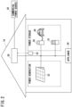
- the electric power device 10 is installed in a residence 18, for example.
- the electric power device 10 charges a mobile battery 12 (see FIG. 1 ) with power supplied from a commercial power source 20 (external power source) or power supplied from a photovoltaic device 22 (external power source). Furthermore, the electric power device 10 supplies power stored in the mobile battery 12 to a home appliance 24 (other power device) inside the residence 18.
- a vehicle 26 (other power device) can be used as a power source device, in addition to the electric power device 10.
- the vehicle 26 includes a drive source battery (not shown).
- the vehicle 26 is a hybrid vehicle or an electric vehicle.
- the vehicle 26 is connected to a vehicle power source manager 28 installed in the residence 18. Due to this, the vehicle 26 and the vehicle power source manager 28 function as power devices.
- the vehicle power source manager 28 charges the drive source battery of the vehicle 26 with power supplied from the commercial power source 20 or power supplied from the photovoltaic device 22.
- the vehicle power source manager 28 supplies the home appliance 24 inside the residence 18 with power stored in the drive source battery.
- An integrated power manager 30 is installed in the residence 18, as an HEMS (Home Energy Management System).
- the integrated power manager 30 manages the power generation amount of the photovoltaic device 22, the power storage amount of the mobile battery 12 of the electric power device 10, and the power storage amount of the drive source battery of the vehicle 26.
- the integrated power manager 30 controls the amount of power supplied to the residence 18 from the commercial power source 20.
- the integrated power manager 30 controls the amount of power supplied to the commercial power source 20 from the residence 18.
- the power system leading to the electric power device 10 from the commercial power source 20, photovoltaic device 22, or vehicle power source manager 28 is an AC power system.
- the integrated power manager 30 can transmit and receive signals or information to and from a portable device 32, via wireless communication.
- the portable device 32 is a smartphone, tablet, or the like possessed by a user.
- the portable device 32 can display various types of information received from the integrated power manager 30, in a display. Specifically, the portable device 32 can display the amount of power supplied to the residence 18 from the commercial power source 20 or the amount of power supplied to the commercial power source 20 from the residence 18, in the display.
- the user can provide their desired instructions to the integrated power manager 30 by checking the display content in the display and operating the portable device 32.
- the electric power device 10 includes four slots 34 and one operation panel 36.
- One mobile battery 12 is set in each of the four slots 34. Openings 38 are formed in the front surface 14 of the electric power device 10, at positions corresponding to each of the slots 34.
- a mobile battery 12 is inserted and removed via the opening 38.
- a battery holder 42 is installed inside each of the four slots 34.
- the battery holder 42 includes a battery tray 40 (attachment portion).
- the electric power device 10 should include at least four slots 34. Accordingly, the electric power device 10 can have at least four mobile batteries 12 attached to four battery trays 40.
- the slot 34 on the top left when the front surface 14 of the electric power device 10 is viewed from the front, is referred to as the first slot 34a.
- the slot 34 on the top right is referred to as the second slot 34b.
- the slot 34 on the bottom left is referred to as the third slot 34c.
- the slot 34 on the bottom right is referred to as the fourth slot 34d. Accordingly, the first slot 34a and second slot 34b are installed at higher positions than the third slot 34c and fourth slot 34d.
- a battery holder 42 having a battery tray 40 is installed in each of the first slot 34a to fourth slot 34d.
- the battery trays 40 installed in the first slot 34a to fourth slot 34d may be referred to respectively as the first battery tray 40a to fourth battery tray 40d (first attachment portion to fourth attachment portion).
- the battery holders 42 of the first slot 34a to fourth slot 34d may be referred to respectively as the first battery holder 42a to fourth battery holder 42d.
- a mobile battery 12 is attached to each of the first battery tray 40a to fourth battery tray 40d.
- the mobile batteries 12 attached to the first battery tray 40a to fourth battery tray 40d may be referred to respectively as a first mobile battery 12a to fourth mobile battery 12d (first power storage device to fourth power storage device) .
- the first battery tray 40a and second battery tray 40b are installed at higher positions than the third battery tray 40c and fourth battery tray 40d.
- the first mobile battery 12a can be attached to and detached from the first battery tray 40a. Furthermore, in the electric power device 10, the second mobile battery 12b can be attached to and detached from the second battery tray 40b.
- the user can exchange any of the mobile batteries among the first mobile battery 12a and the second mobile battery 12b. Specifically, the user can exchange a mobile battery whose deterioration degree has become high, due to repeated charging and discharging, with a mobile battery whose deterioration degree is low.
- the deterioration degree is the SOH (State Of Health), for example.
- the third mobile battery 12c attached to the third battery tray 40c is a power storage device that has been fixed to the third battery tray 40c (made stationary).
- the fourth mobile battery 12d attached to the fourth battery tray 40d is a power storage device that has been fixed to the fourth battery tray 40d (made stationary).
- the stationary third mobile battery 12c and fourth mobile battery 12d may be always fixed to the third battery tray 40c and fourth battery tray 40d.
- the third mobile battery 12c and fourth mobile battery 12d may be power storage devices whose attachment and detachment frequencies are less than those of the first mobile battery 12a and second mobile battery 12b. In this case, the third mobile battery 12c and fourth mobile battery 12d can be attached or detached when their lifetime has expired, for example.
- At least two mobile batteries 12 that are attachable to and detachable from the electric power device 10 can be stored in the electric power device 10.
- at least two mobile batteries 12 (the third mobile battery 12c and the fourth mobile battery 12d) that are fixed to the electric power device 10 can be stored in the electric power device 10. Therefore, in the present embodiment, the electric power device 10 can store 32 mobile batteries 12, for example. In such a case, two mobile batteries 12 are fixed to the electric power device 10. Furthermore, 30 mobile batteries 12 are attachable to and detachable from the electric power device 10. That is, in the present embodiment, two or more mobile batteries 12 should be attachable to and detachable from the electric power device 10.
- the operation panel 36 is arranged on the front surface 14 of the electric power device 10, above the first slot 34a to fourth slot 34d. As shown in FIG. 3 , the operation panel 36 is provided with a first unlock button 44a to fourth unlock button 44d (instructing sections), a first unlock notification section 46a to fourth unlock notification section 46d (notifying sections), and a first charging completion notification section 48a to fourth charging completion notification section 48d.
- the first unlock button 44a to fourth unlock button 44d correspond to the first slot 34a to fourth slot 34d shown in FIG. 1 (first battery tray 40a to fourth battery tray 40d). As shown in FIG. 3 , the first unlock notification section 46a to fourth unlock notification section 46d are arranged to surround the first unlock button 44a to fourth unlock button 44d. The first charging completion notification section 48a to fourth charging completion notification section 48d are arranged to the right side of the first unlock button 44a to fourth unlock button 44d.
- the first battery holder 42a to fourth battery holder 42d are each provided with a lock portion 50 (restraining portion) (see FIGS. 4 and 5 ).
- the lock portions 50 respectively put the first battery tray 40a to fourth battery tray 40d in a locked state (restrained state) when the first battery tray 40a to fourth battery tray 40d are oriented upward. In the locked state, the first mobile battery 12a to fourth mobile battery 12d cannot be removed from the first battery holder 42a to fourth battery holder 42d.
- the first unlock notification section 46a to fourth unlock notification section 46d are LED lamps.
- the unlock notification sections 46a to 46d surrounding the operated unlock button 44a to 44d light up.
- the lock portions 50 corresponding to the operated unlock button 44a to 44d unlock the battery trays 40.
- the mobile battery 12 placed in the battery tray 40 that has been unlocked tilts slowly forward along with this battery tray 40.
- the battery tray 40 rotates backward to be oriented upward. Accordingly, when a certain time (prescribed time) has passed from the unlocking, the lock portion 50 causes the battery tray 40 to be in the locked state again. Due to this, the unlock notification section 46a to 46d no longer lights up.
- the third mobile battery 12c is fixed to the third battery tray 40c. Furthermore, the fourth mobile battery 12d is fixed to the fourth battery tray 40d. Therefore, the third battery tray 40c and fourth battery tray 40d are always in the locked state. Accordingly, even when the third unlock button 44c or fourth unlock button 44d is operated, the user operation is invalid.
- the first charging completion notification section 48a to fourth charging completion notification section 48d are LED lamps.
- the first charging completion notification section 48a to fourth charging completion notification section 48d light up when the respective first mobile battery 12a to fourth mobile battery 12d are fully charged.
- a door portion 54 is provided on the front surface 14 of the electric power device 10.
- a reinforcement rib 56 and four battery guides 58 are provided on the rear surface (back surface) of the door portion 54.
- the reinforcement rib 56 includes two up-down-direction ribs 60 and two lateral-direction ribs 62.
- the two up-down-direction ribs 60 are separated by a constant interval and provided on the rear surface of the door portion 54.
- Each of the two up-down-direction ribs 60 extends in the up-down-direction direction (Z-axis direction).
- the two lateral-direction ribs 62 are separated by a constant interval and provided on the rear surface of the door portion 54.
- Each of the two lateral-direction ribs 62 extends in a direction orthogonal to the up-down-direction ribs 60.
- the four battery guides 58 are provided overlapping with the two up-down-direction ribs 60.
- the four battery guides 58 are provided to the two up-down-direction ribs 60 in a manner to respectively face the first slot 34a to fourth slot 34d.
- the four battery guides 58 are provided to the two up-down-direction ribs 60 in a manner to face the first mobile battery 12a to fourth mobile battery 12d set in the first slot 34a to fourth slot 34d.
- the four battery guides 58 are provided on the two up-down-direction ribs 60 at positions corresponding to the top portions of the first mobile battery 12a to fourth mobile battery 12d.
- Each battery guide 58 is formed to extend backward from the door portion 54 in a state where the door portion 54 is closed.
- Each of the four battery guides 58 prevents the mobile battery 12 from falling forward while the mobile battery 12 is stored in the slot 34. Due to this, it is possible to prevent the mobile battery 12 from detaching from the battery tray 40. Furthermore, when a vibration acts on the electric power device 10, it is possible to restrict movement of the mobile battery 12 within the electric power device 10 and the like. Yet further, in a state where the mobile battery 12 has detached from the battery tray 40, the mobile battery 12 and the battery guide 58 interfere with each other when the door portion 54 is closed. In such a case, the door portion 54 is not completely closed, and it is possible for the user to recognize that a mobile battery 12 has detached from the battery tray 40.
- the electric power device 10 is not limited to being used in the residence 18, and can be applied to various power source systems that supply power to a load or the like from the plurality of mobile batteries 12 or charge the plurality of mobile batteries 12.
- the electric power device 10 is not limited to being used in the residence 18, and can be installed in an office, a public facility, or the like.
- the electric power device 10 can be applied to power source systems of various types of moving bodies.
- the various types of moving bodies including moving bodies that can be ridden by people and moving bodies that cannot be ridden by people.
- Examples of such moving bodies include vehicles, aircraft, flying bodies, ships, and the like.
- Examples of a power source system of a vehicle include a power source system of an electric vehicle and a power source system of a vehicle having a drive motor, such as a hybrid vehicle. That is, the electric power device 10 can be applied to the power systems of various types of vehicles such as one-wheel vehicles, two-wheel vehicles, and four-wheel vehicles.
- the electric power device 10 can be applied to the power source system of various types of general-purpose equipment not ridden by people.
- general-purpose equipment includes, for example, (1) a charger, (2) a discharger, (3) work machines such as general-purpose work machines, lawn mowers, cultivators, and blowers, (4) electric equipment without a motor, such as floodlights and lighting equipment, and (5) equipment installed in houses or buildings.
- Examples of (5) above include (A) equipment that operates on DC power, such as clocks and audio equipment such as radio cassette recorders, (B) equipment that operates on AC power such as fans, juicers, blenders, incandescent lamps, and the like, (C) equipment that operates on DC power converted from AC power, such as televisions, radios, stereos, and personal computers, and (D) inverter-type devices including washing machines, refrigerators, air conditioners, microwave ovens, and fluorescent lamps.
- the devices of (D) above include devices that operate on AC power converted from DC power obtained previously from converting AC power to this DC power.
- FIGS. 1 to 3 will also be referenced as necessary.
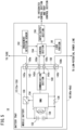
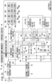
- the electric power device 10 includes two breakers 70 and 72 and two inverters 74 and 76 (power converter devices).
- the electric power device 10 is electrically connected to an AC power system such as the commercial power source 20 (see FIG. 2 ), via a connection portion 77 such as an AC outlet.
- the line from the connection portion 77 branches into two lines.
- one line is electrically connected to the first inverter 74 via the first breaker 70.
- the other line is electrically connected to the second inverter 76 via the second breaker 72.
- a serial circuit including the first breaker 70 and the first inverter 74 and a serial circuit including the second breaker 72 and the second inverter 76 are electrically connected in parallel with respect to the connection portion 77.
- the first inverter 74 converts the AC voltage from the commercial power source 20 into a relatively low DC voltage (power source voltage for driving the control circuit).
- the second inverter 76 converts the AC voltage from the commercial power source 20 into a relatively high DC voltage (high DC voltage for charging).
- the second inverter 76 converts a high DC voltage (high DC voltage for discharge) into an AC voltage.
- the electric power device 10 further includes, in addition to the operation panel 36, an integrated control section 78 (estimating section and control section), a relay control section 80, and a tray control section 82.
- the low DC voltage resulting from the conversion by the first inverter 74 is supplied to the integrated control section 78, the relay control section 80, the tray control section 82, and the operation panel 36. That is, the low DC voltage is the power source voltage for driving the integrated control section 78, the relay control section 80, the tray control section 82, and the operation panel 36.
- the integrated control section 78, the relay control section 80, the tray control section 82, and the operation panel 36 are a control system for the first mobile battery 12a to fourth mobile battery 12d, first battery tray 40a to fourth battery tray 40d, and the like.
- the electric power device 10 further includes a first circuit 84 to third circuit 88.
- the first circuit 84 to third circuit 88 are electrically connectable to the first mobile battery 12a to fourth mobile battery 12d, which are attached to the first battery tray 40a to fourth battery tray 40d.
- the second circuit 86 is a high-potential line connected to the positive terminal of the output side (secondary side) of the second inverter 76.
- the third circuit 88 is a low-potential (e.g., a ground potential) line connected to the negative terminal of the output side of the second inverter 76.
- the first circuit 84 is a line for generating an intermediate potential (neutral point potential) between the second circuit 86 and the third circuit 88.
- the high DC voltage generated on the output side of the second inverter 76 is a charge voltage to be supplied from the second inverter 76 to the first mobile battery 12a to fourth mobile battery 12d, via the first circuit 84 to third circuit 88.
- the high DC voltage generated on the output side of the second inverter 76 is a discharge voltage to be output from the first mobile battery 12a to fourth mobile battery 12d to the second inverter 76, via the first circuit 84 to third circuit 88.
- the first battery tray 40a and the second battery tray 40b are arranged to be electrically connected in series.
- the first battery tray 40a and second battery tray 40b are electrically connected to the first circuit 84.
- the first circuit 84 is arranged between the first battery tray 40a and the second battery tray 40b, as shown in FIG. 4 .
- One end portion of the first battery tray 40a faces the first circuit 84 (second battery tray 40b).
- the one end portion of the first battery tray 40a is electrically connected to the negative electrode of the first mobile battery 12a, when the first mobile battery 12a is attached.
- One end portion of the second battery tray 40b faces the first circuit 84 (first battery tray 40a).
- the one end portion of the second battery tray 40b is electrically connected to the positive electrode of the second mobile battery 12b, when the second mobile battery 12b is attached.
- the second circuit 86 is electrically connected to the side of the first battery tray 40a opposite the side connected to the first circuit 84.
- the second circuit 86 is electrically connected to the positive terminal of the output side of the second inverter 76.
- the second circuit 86 is electrically connected to the other end portion of the first battery tray 40a.
- the other end portion of the first battery tray 40a is the side of the first battery tray 40a opposite the first circuit 84 (the side away from the second battery tray 40b).
- the other end portion of the first battery tray 40a is electrically connected to the positive electrode of the first mobile battery 12a, when the first mobile battery 12a is attached.
- the third circuit 88 is electrically connected to the side of the second battery tray 40b opposite the side connected to the first circuit 84.
- the third circuit 88 is electrically connected to the negative terminal of the output side of the second inverter 76.
- the third circuit 88 is electrically connected to the other end portion of the second battery tray 40b.
- the other end portion of the second battery tray 40b is the side of the second battery tray 40b opposite the first circuit 84 (the side away from the first battery tray 40a).
- the other end portion of the second battery tray 40b is electrically connected to the negative electrode of the second mobile battery 12b, when the second mobile battery 12b is attached.
- a first resistance portion 90 and a fuse 92 are electrically connected in series to the first battery tray 40a, between the first circuit 84 and the second circuit 86.
- a first interruption portion 94 which is a relay, is electrically connected in parallel to the first resistance portion 90. It is sufficient for the first battery tray 40a, the parallel circuit made up of the first resistance portion 90 and the first interruption portion 94, and the fuse 92 to be electrically connected in parallel. Therefore, the configuration is not limited to the example of FIG. 4 , and the first battery tray 40a may be connected to the second circuit 86. Furthermore, the parallel circuit made up of the first resistance portion 90 and the first interruption portion 94 may be connected to the first circuit 84.
- a second resistance portion 96 and a fuse 98 are electrically connected in series to the second battery tray 40b, between the first circuit 84 and the third circuit 88.
- a second interruption portion 100 which is a relay, is electrically connected in parallel to the second resistance portion 96. It is sufficient for the second battery tray 40b, the parallel circuit made up of the second resistance portion 96 and the second interruption portion 100, and the fuse 98 to be electrically connected in parallel. Therefore, the configuration is not limited to the example of FIG. 4 , and the second battery tray 40b may be connected to the third circuit 88. Furthermore, the parallel circuit made up of the second resistance portion 96 and the second interruption portion 100 may be connected to the first circuit 84.
- a serial circuit made up of the third battery tray 40c and the fuse 102 is electrically connected between the first circuit 84 and the second circuit 86.
- This serial circuit is electrically connected in parallel to the first battery tray 40a, the fuse 92, and the parallel circuit made up of the first resistance portion 90 and the first interruption portion 94.
- one end portion of the third battery tray 40c (negative electrode of the third mobile battery 12c) is electrically connected to the first circuit 84.
- the other end portion of the third battery tray 40c (positive electrode of the third mobile battery 12c) is electrically connected to the second circuit 86, via the fuse 102.
- a serial circuit made up of the fourth battery tray 40d and a fuse 104 is electrically connected between the first circuit 84 and the third circuit 88.
- This serial circuit is electrically connected in parallel to the second battery tray 40b, the fuse 98, and the parallel circuit made up of the second resistance portion 96 and the second interruption portion 100.
- one end portion of the fourth battery tray 40d (positive electrode of the fourth mobile battery 12d) is electrically connected to the first circuit 84, via the fuse 104.
- the other end portion of the fourth battery tray 40d (negative electrode of the fourth mobile battery 12d) is electrically connected to the third circuit 88.
- a parallel circuit made up of a first voltage-dividing resistor 106 and a first voltage-dividing capacitor 108 is electrically connected between the first circuit 84 and the second circuit 86.
- a parallel circuit made up of a second voltage-dividing resistor 110 and a second voltage-dividing capacitor 112 is electrically connected between the first circuit 84 and the third circuit 88.
- a relay 114 and a fuse 116 are electrically connected in series in the second circuit 86.
- the relay 114 and the fuse 116 are connected between the third battery tray 40c and the first voltage-dividing resistor 106 and first voltage-dividing capacitor 108, in the second circuit 86.
- a relay 118 and a fuse 120 are electrically connected in series in the third circuit 88.
- the second voltage-dividing capacitor 118 and the fuse 120 are arranged between the fourth battery tray 40d and the second voltage-dividing resistor 110 and second voltage-dividing capacitor 112, in the third circuit 88.
- the second inverter 76 can charge the first mobile battery 12a to fourth mobile battery 12d attached to the first battery tray 40a to fourth battery tray 40d, via the first circuit 84 to third circuit 88.
- the second inverter 76 is capable of extracting DC power from the first mobile battery 12a to fourth mobile battery 12d attached to the first battery tray 40a to fourth battery tray 40d, via the first circuit 84 to third circuit 88.
- the first circuit 84 functions as wiring generating a DC voltage having an intermediate potential with respect to the high-potential DC voltage at the second circuit 86 and the low-potential DC voltage at the third circuit 88.
- the first voltage-dividing resistor 106 and the first voltage-dividing capacitor 108 are provided between the first circuit 84 and the second circuit 86.
- the second voltage-dividing resistor 110 and the second voltage-dividing capacitor 112 are provided between the first circuit 84 and the third circuit 88. Due to this, a DC voltage of the intermediate potential is generated at the first circuit 84.
- the voltage of the output side of the second inverter 76 is divided, and therefore it is possible to restrict the occurrence of overvoltage.
- the first mobile battery 12a and the third mobile battery 12c are charged with the DC voltage of the potential difference between the first circuit 84 and the second circuit 86. Furthermore, the first mobile battery 12a and the third mobile battery 12c discharge with the DC voltage of the potential difference between the first circuit 84 and the second circuit 86.
- the second mobile battery 12b and the fourth mobile battery 12d are charged with the DC voltage of the potential difference between the first circuit 84 and the third circuit 88. Furthermore, the second mobile battery 12b and the fourth mobile battery 12d discharge with the DC voltage of the potential difference between the first circuit 84 and the third circuit 88.
- the integrated control section 78 is a computer that performs integrated control of each section of the electric power device 10.
- the integrated control section 78 functions as the estimating section and the control section, by reading and executing a program stored in a memory (not shown). In this case, it is possible to realize the function of the integrated control section 78 simply and with a low cost by using a single-board computer such as a Raspberry Pi (Registered Trademark).
- a single-board computer such as a Raspberry Pi (Registered Trademark).
- the detailed functions of the integrated control section 78 are described further below.
- the integrated control section 78 is capable of transmitting and receiving signals and information to and from the two inverters 74 and 76, the relay control section 80, the tray control section 82, and the first battery tray 40a to fourth battery tray 40d, via a communication line 122 such as a CAN (Controller Area Network).
- the electric power device 10 further includes a communication section 124.
- the integrated control section 78 is capable of transmitting and receiving signals and information to and from the integrated power manager 30, via the communication section 124. Due to this, the integrated control section 78 can perform control corresponding to the content of the operation of the portable device 32 performed by the user, via the communication section 124 and the integrated power manager 30. Furthermore, the integrated control section 78 can transmit various types of information of the electric power device 10 to the portable device 32, via the communication section 124 and the integrated power manager 30.
- the relay control section 80 switches the first interruption portion 94, the second interruption portion 100, and each of the relays 114 and 118 to an OFF state (cutoff state) or an ON state (connected state), according to control from the integrated control section 78.
- the tray control section 82 controls the first battery tray 40a to fourth battery tray 40d, the first mobile battery 12a to fourth mobile battery 12d attached to the first battery tray 40a to fourth battery tray 40d, and each lock portion 50.
- the tray control section 82 performs the above control according to control from the integrated control section 78 and operation of the first unlock button 44a to fourth unlock button 44d performed by the user. Furthermore, the tray control section 82 performs control to light up or extinguish the first unlock notification section 46a to the fourth unlock notification section 46d and the first charging completion notification section 48a to the fourth charging completion notification section 48d.
- the electric power device 10 can also have a structure in which a plurality of serial circuits that are each made up of two mobile batteries 12 are connected in parallel to the serial circuit made up of the two mobile batteries 12c and 12d that are fixed.
- FIG. 5 is a circuit configuration diagram of the plurality of battery trays 40 (first battery tray 40a to fourth battery tray 40d) and the mobile batteries 12 (first mobile battery 12a to fourth mobile battery 12d) connected respectively to these battery trays 40.
- first battery tray 40a to fourth battery tray 40d the mobile batteries 12
- FIG. 5 only one battery tray 40 and the mobile battery 12 attached to this battery tray 40 are shown.
- the configurational components of the electric power device 10 other than the battery tray 40 and the mobile battery 12 are shown in a simplified manner.
- each of the plurality of mobile batteries 12 includes a switch 130, a battery 132, a battery management system (BMU) 134, a resistor 136, a temperature sensor 138, a communication section 140, and a connector 142.
- Each mobile battery 12 is a battery pack that stores these configurational elements.
- the fuse 130 is a semiconductor switch such as a FET (Field Effect Transistor).
- the positive electrode of the battery 132 is electrically connected to a positive terminal 142a of the connector 142, via the switch 130.
- the negative electrode of the battery 132 is electrically connected to a negative terminal 142b of the connector 142, via the resistor 136.
- the communication section 140 is connected to a signal terminal 142c of the connector 142.
- the communication section 140 is connected to an activation signal terminal 142d.
- the battery tray 40 includes a connector 150, an engagement detection sensor 152, a control section 154, the lock portion 50, and an input/output section 156.
- the connector 150 includes a positive terminal 150a, a negative terminal 150b, a signal terminal 150c, and an activation signal terminal 150d.
- the positive terminal 150a is electrically connected to one of the fuses 92, 98, 102, and 104 (see FIG. 4 ).
- the negative terminal 150b is electrically connected to the first circuit 84 or the third circuit 88.
- the first circuit 84 or the third circuit 88 is a low-potential line.
- the signal terminal 150c and the activation signal terminal 150d are connected to the control section 154.
- the connector 150 of the battery tray 40 engages with the connector 142 of the mobile battery 12.
- the positive terminal 142a and the positive terminal 150a become electrically connected.
- the negative terminal 142b and the negative terminal 150b become electrically connected.
- the signal terminal 142c and the signal terminal 150c become electrically connected.
- the activation signal terminal 142d and the activation signal terminal 150d become electrically connected.
- the engagement detection sensor 152 detects the presence or lack of engagement between the connector 142 and the connector 150, and outputs this detection result to the control section 154.
- the input/output section 156 is connected to the communication line 122.
- the input/output section 156 can transmit and receive signals or information to and from the integrated control section 78 and the tray control section 82, via the communication line 122.
- the input/output section 156 receives the supply of DC voltage for driving, from the tray control section 82.
- the lock portion 50 sets the battery tray 40 to the locked state. Alternatively, the lock portion 50 unlocks the battery tray 40.
- the control section 154 is driven by the DC voltage supplied from the tray control section 82 via the input/output section 156. Due to this, the control section 154 controls each section within the battery tray 40. Furthermore, the control section 154 transmits the detection result of the engagement detection sensor 152 to the integrated control section 78, via the input/output section 156 and the communication line 122. Yet further, when each of the connectors 142 and 150 are connected, the control section 154 supplies the BMU 134 with an activation signal via each of the activation signal terminals 142d and 150d. The BMU 134 receives the supply of the activation signal to be activated.
- control section 154 transmits and receives signals or information to and from the mobile battery 12, via each of the signal terminals 142c and 150c. Due to this, the control section 154 transmits the information received from the mobile battery 12 to the integrated control section 78 and the like, via the input/output section 156 and the communication line 122. The control section 154 transmits the instructions coming from the integrated control section 78 to the mobile battery 12. The control section 154 controls the lock portion 50 by outputting the instructions from the tray control section 82 to the lock portion 50.
- the BMU 134 is activated in response to the activation signal being supplied from the control section 154. That is, the BMU 134 is activated by receiving the power supply from a power source (not shown) inside the mobile battery 12, based on the supply of the activation signal.
- the low DC voltage for driving is supplied from the tray control section 82 to the battery tray 40. Therefore, the BMU 134 can be activated by receiving the supply of the DC voltage for driving via each of the connectors 142 and 150, based on the supply of the activation signal.
- the BMU 134 performs monitoring and the like of the battery 132. Specifically, the BMU 134 electrically connects the battery 132 with the first circuit 84 to third circuit 88 by turning ON the switch 130. When a control signal is received by the communication section 140 via each signal terminal 142c and 150c from the control section 154, the BMU 134 turns ON the switch 130 based on the control signal. Furthermore, the BMU 134 sequentially detects the voltage value at both ends of the resistor 136. The BMU 134 sequentially calculates the current value of the current (battery current) flowing through the battery 132, based on the detected voltage values and the resistance value of the resistor 136.
- the BMU 134 sequentially detects the value (voltage value) of the voltage (battery voltage) of the battery 132.
- the BMU 134 sequentially calculates the SOC of the battery 132, based on the detected voltage values and the calculated current values.
- the BMU 134 sequentially acquires the temperature of the battery 132 detected by the temperature sensor 138 such as a thermistor. In the following description, the temperature of the battery 132 is referred to as the battery temperature.
- the BMU 134 sequentially transmits various types of information to the control section 154 of the battery tray 40 from the communication section 140, via each of the signal terminals 142c and 150c.
- the various types of information include the voltage values, current values, SOCs, and battery temperatures.
- the characteristic functions of the present embodiment are the following (1) to (3).
- (1) The resistance value of the first resistance portion 90 (see FIG. 4 ) is determined.
- the integrated control section 78 functions as the estimating section that estimates the current flowing through the first mobile battery 12a when the first interruption portion 94 is ON.
- (3) The integrated control section 78 functions as the control section that controls the first interruption portion 94 based on the estimated current.
- the following describes each of the functions (1) to (3).
- FIG. 6 is a circuit configuration diagram in which the circuit connections between the first mobile battery 12a and the third mobile battery 12c are simplified.
- the first mobile battery 12a, the third mobile battery 12c, the first resistance portion 90, and the wiring (first circuit 84 and second circuit 86) electrically connecting these configurational elements are shown.
- the maximum voltage of the first mobile battery 12a attached to the first battery tray 40a is V1max.
- the minimum voltage of the first mobile battery 12a is V1min.
- the number of cells of the battery 132 forming the first mobile battery 12a is N1cell.
- the maximum value of the cell voltage (maximum cell voltage) of the battery 132 is V1cellmax.
- the minimum value of the cell voltage (minimum cell voltage) of the battery 132 is V1cellmin.
- the maximum cell voltage Vicellmax is the cell voltage when the SOC of the first mobile battery 12a is at the maximum (for example, SOC: 100%).
- the minimum cell voltage V1cellmin is the cell voltage when the SOC of the first mobile battery 12a is at a minimum.
- the maximum voltage of the third mobile battery 12c attached to the third battery tray 40c is V3max.
- the minimum voltage of the third mobile battery 12c is V3min.
- the number of cells of the battery 132 forming the third mobile battery 12c is N3cell.
- the maximum cell voltage of the battery 132 is V3cellmax.
- the minimum cell voltage of the battery 132 is V3cellmin.
- V1max V1cellmax ⁇ N1cell
- V1min V1cellmin ⁇ N1cell
- V3max V3cellmax ⁇ N3cell
- V3min V3cellmin ⁇ N3cell
- the first resistance portion 90 is provided in the electric power device 10.
- the first resistance portion 90 is a current limiting resistor for overcurrent.
- the maximum value of the charge current or discharge current (maximum charge/discharge current) flowing to the first mobile battery 12a is Imax.
- Rrlmin which is the minimum value of the resistance value Rr1 (minimum resistance value) of the first resistance portion 90, is expressed as shown in Expression (6) below.
- Rr1min V13max / Imax
- the resistance value Rr1 of the first resistance portion 90 should be set to be greater than or equal to the minimum resistance value Rr1min.
- the first resistance portion 90 is a resistor rated for power consumption greater than or equal to the tolerable power value P1max, it is possible to effectively restrict the occurrence of overcurrent.
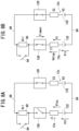
- FIGS. 7A and 7B are each a circuit configuration diagram in which the circuit connections among the first mobile battery 12a, the third mobile battery 12c, and the second inverter 76 are simplified.
- the first mobile battery 12a, the third mobile battery 12c, the first resistance portion 90, the first interruption portion 94, the second inverter 76, and the wiring (first circuit 84 and second circuit 86) electrically connecting these configurational elements are shown.
- the first mobile battery 12a is shown schematically by a serial circuit made up of the battery 132 and an internal impedance Z1.
- the third mobile battery 12c is shown schematically by a serial circuit made up of the battery 132 and an internal impedance Z3.
- the internal impedances Z1 and Z3 are usually expressed by a resistance portion and a reactance portion. In the following description, for the sake of convenience, the internal impedances Z1 and Z3 are expressed by absolute values.
- the first resistance portion 90 functions as a current limiting resistor for overcurrent. Therefore, if the current I1 flowing to the first mobile battery 12a becomes less than or equal to the tolerable current value I1th, the first interruption portion 94 is preferably switched from OFF (cutoff state) to ON (connected state). By switching the first interruption portion 94 ON, the first resistance portion 90 is shorted. If the first interruption portion 94 is in the OFF state, the integrated control section 78 estimates the estimated current I1on, which is the current value expected to be flowing to the first mobile battery 12a when it is assumed that the first interruption portion 94 is in the ON state. If the estimated current I1on is less than or equal to the tolerable current value I1th, the integrated control section 78 switches the first interruption portion 94 from OFF to ON. Specifically, the estimated current I1on is estimated using the following technique.
- FIG. 7A is a circuit configuration diagram occurring when the first interruption portion 94 is in the OFF state.
- the current flowing from the second inverter 76 is I.
- the current (first current) flowing to the first mobile battery 12a is I1off.
- the current (first current) flowing to the third mobile battery 12c is I3off.
- Vsys V1 + Z1 + Rr1 ⁇ I1off
- Vsys V3 + Z3 ⁇ I3off
- FIG. 7B is a circuit configuration diagram occurring when the first interruption portion 94 is in the ON state.
- the current (estimated current) flowing to the first mobile battery 12a is I1on.
- the current (estimated current) flowing to the third mobile battery 12c is I3on.
- the integrated control section 78 estimates the estimated current I1on using Expression (17) above.
- the integrated control section 78 judges whether this estimated current I1on is less than or equal to the tolerable current value I1th.
- the integrated control section 78 determines whether to switch the first interruption portion 94 from OFF to ON, based on this judgment result.
- the above description is a description for estimating the estimated current I1on flowing through the first mobile battery 12a.
- the above description should be changed in the following manner.
- instances of "first” should be replaced with “second” and instances of "third” should be replaced with “fourth”.
- the integrated control section 78 can estimate the current I2on flowing through the second mobile battery 12b. Therefore, a detailed description concerning the estimation technique for the current I2on is omitted.
- FIGS. 8A and 8B are each a circuit configuration diagram in which the circuit connections between the first mobile battery 12a and the third mobile battery 12c are simplified.
- the switches 130 of the first mobile battery 12a and the third mobile battery 12c are also shown.
- FIG. 8A shows a case in which the switch 130 of the first mobile battery 12a is OFF.
- FIG. 8B shows a case in which the switch 130 of the first mobile battery 12a is ON.
- the first interruption portion 94 is in the OFF state.
- the switch 130 of the third mobile battery 12c is ON.
- the battery voltage V1 is a voltage value measured by the BMU 134.
- the battery voltage V1 is a voltage value that is affected by the internal impedance Z1. That is, the battery voltage V1 is the sum of V1t, which is the true voltage of the battery 132 (total of the cell voltages of each cell forming the battery 132), and the voltage drop Vdrop. Accordingly, the battery voltage V1 is expressed by Expression (19) below.
- Vdrop V 1 ⁇ V 1 t
- Vdrop V 1 ⁇ V 1 oc
- the integrated control section 78 calculates the internal impedance Z1 using Expression (21) above. Furthermore, the integrated control section 78 can estimate the estimated current I1on using the estimated internal impedance Z1.
- the above description is for calculating the internal impedance Z1 of the first mobile battery 12a.
- a description of calculating the internal impedance Z3 of the third mobile battery 12c is realized. That is, by performing such a replacement, the integrated control section 78 can calculate the internal impedance Z3. Therefore, a detailed description of a technique for estimating the internal impedance Z3 is omitted.
- the integrated control section 78 controls the first interruption portion 94, based on the estimated current I1on. That is, the integrated control section 78 switches the first interruption portion 94 from OFF to ON if the estimated current I1on is less than or equal to the tolerable current value I1th. Furthermore, the integrated control section 78 keeps the OFF state of the first interruption portion 94 if the estimated current I1on exceeds the tolerable current value I1th.
- the integrated control section 78 instructs the relay control section 80 to switch the first interruption portion 94 to one of the ON state or the OFF state, based on the above determination result. Due to this, the relay control section 80 switches the first interruption portion 94 to one of the ON state or the OFF state according to the content of the instructions from the integrated control section 78.
- the above description is for switching the first interruption portion 94 to the ON state or the OFF state.
- a description is realized for switching the second interruption portion 100 to the ON state or the OFF state. That is, by replacing instances of the "first interruption portion 94" with the "second interruption portion 100", the second interruption portion 100 can be switched to the ON state or the OFF state. Therefore, a detailed description of switching the second interruption portion 100 to the ON state or the OFF state is omitted.
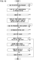
- FIGS. 9 and 10 The operation of the electric power device 10 (control method of the electric power device 10) configured as described above will be described while referencing FIGS. 9 and 10 .
- the operation in a case of attaching the first mobile battery 12a to the first battery tray 40a will be described.
- the operation in a case of removing the first mobile battery 12a from the first battery tray 40a will be described.
- FIGS. 1 to 8B will also be referenced as necessary.
- a case of attaching the second battery tray 40b to the second mobile battery 12b and a case of removing the second mobile battery 12b from the second battery tray 40b are similar to the above.
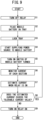
- the integrated control section 78 instructs the relay control section 80 to set the first interruption portion 94 to the OFF state. Due to this, the relay control section 80 sets the first interruption portion 94, which is a relay, to the OFF state.
- the user places the first mobile battery 12a on the first battery tray 40a. Due to this, the first mobile battery 12a is stored within the first slot 34a in a state of being attached to the first battery tray 40a.
- the connector 142 of the first mobile battery 12a engages with the connector 150 of the first battery tray 40a.
- the engagement detection sensor 152 detects the engagement state between the two connectors 142 and 150, and outputs the detection result to the control section 154.
- the control section 154 transmits the detection result to the integrated control section 78, via the input/output section 156 and the communication line 122.
- the lock portion 50 sets the first battery tray 40a attached to the first mobile battery 12a to the locked state, based on the detection result of the engagement detection sensor 152 output to the control section 154. Due to this, it is possible to prevent the first mobile battery 12a from being removed from the first battery tray 40a.
- the integrated control section 78 instructs the control section 154 of the first battery tray 40a, via the communication line 122, to start the power source supply to the first mobile battery 12a. Due to this, the control section 154 supplies the activation signal to the BMU 134 of the first mobile battery 12a, via each of the activation signal terminals 142d and 150d, according to the instructions from the integrated control section 78. Due to this, the BMU 134 is activated by receiving the power supply from a power source section (not shown), based on the supply of the activation signal. Alternatively, the BMU 134 is activated by receiving the supply of the DC voltage for driving from the first battery tray 40a, via each of the connectors 142 and 150.
- the BMU 134 starts communication with the control section 154 via the communication section 140 and each of the signal terminals 142c and 150c. Due to this, the BMU 134 can transmit and receive signals or information to and from the integrated control section 78, via the control section 154, the input/output section 156, and the communication line 122.
- the BMU 134 turns ON the switch 130. Due to this, the first mobile battery 12a is electrically connected to the first circuit 84 and the second circuit 86, via the first battery tray 40a.
- the BMU 134 may turn ON the switch 130 according to the instructions received from the integrated control section 78 via the communication line 122 and the control section 154. Alternatively, the BMU 134 may turn ON the switch 130 according to the instructions from the control section 154. Alternatively, the BMU 134 may turn ON the switch 130 upon activation.
- the BMU 134 measures the battery voltage, the battery current, the battery temperature, and the SOC of the first mobile battery 12a. These measurement results are transmitted to the integrated control section 78 via the communication section 140, each of the signal terminals 142c and 150c, the control section 154, the input/output section 156, and the communication line 122.
- the integrated control section 78 estimates the estimated current I1on, using Expression (17), based on each of the measurement results received from the BMU 134 of the first mobile battery 12a.
- the estimated current I1on is the current that flows to the first mobile battery 12a when it is assumed that the first interruption portion 94 enters the ON state.
- the internal impedance Z1 of the first mobile battery 12a, the resistance value Rr1 of the first resistance portion 90, and the internal impedance Z3 of the third mobile battery 12c are calculated in advance, and stored in a memory (not shown).
- the current I1off is the current value measured in step S6.
- the integrated control section 78 can transmit and receive signals and information to and from the control section 154 of the third mobile battery 12c and the second inverter 76, via the communication line 122. Therefore, the integrated control section 78 is capable of receiving the measurement result of the current I3off from the control section 154 of the third mobile battery 12c. Furthermore, the integrated control section 78 is capable of receiving the measurement result of the current I flowing through the output side of the second inverter 76.
- step S8 the integrated control section 78 determines whether the estimated current I1on, which was estimated in step S7, exceeds the tolerable current value I1th.
- step S8 YES
- the integrated control section 78 determines that the first interruption portion 94 is remaining in the OFF state. This is because, when the first interruption portion 94 is switched from OFF to ON, there is a possibility that overcurrent that exceeds the tolerable current value I1th may flow to the first mobile battery 12a. Due to this, the integrated control section 78 returns to step S6, and repeats the processing of steps S6 to S8.
- step S8 the integrated control section 78 proceeds to step S9.
- step S9 the integrated control section 78 judges that, even if the first interruption portion 94 is switched from OFF to ON, overcurrent exceeding the tolerable current value I1th will not flow to the first mobile battery 12a.
- the integrated control section 78 determines that the first interruption portion 94 is to be switched from OFF to ON, based on the judgment result.
- the integrated control section 78 outputs instructions for switching the first interruption portion 94 from OFF to ON to the relay control section 80 via the communication line 122. Due to this, the relay control section 80 switches the first interruption portion 94 from OFF to ON. As a result, the first resistance portion 90 is shorted by the first interruption portion 94. In this state, power is supplied to and discharged from the first mobile battery 12a.
- the current I2on flowing to the second mobile battery 12b may also be estimated. Furthermore, in a case where I1on ⁇ I1th and I2on ⁇ I2th, the first interruption portion 94 may be switched from OFF to ON.
- step S10 When the user presses the first unlock button 44a at step S10 of FIG. 10 (step S10: YES), the process proceeds to step S11, and the first unlock notification section 46a lights up.
- the tray control section 82 instructs the control section 154 of the first battery tray 40a to unlock the first battery tray 40a.
- the control section 154 controls the lock portion 50 according to the instructions from the tray control section 82, and unlocks the first battery tray 40a.
- the control section 154 transmits to the integrated control section 78, via the input/output section 156 and the communication line 122, notification that the first battery tray 40a has been unlocked.
- the integrated control section 78 receives information about the unlocking.
- the integrated control section 78 instructs the control section 154 of the first battery tray 40a, via the communication line 122, to stop the power source supply to the first mobile battery 12a. Due to this, the control section 154 stops the supply of the activation signal to the BMU 134, according to the instructions from the integrated control section 78. As a result, the BMU 134 is turned OFF. As a result, the switch 130 is also turned OFF. Therefore, the transmission and reception of signals or information between the BMU 134 and the control section 154 and integrated control section 78 is stopped. Due to this, the integrated control section 78 can know that communication with the first mobile battery 12a has been discontinued. That is, the integrated control section 78 can know that the operation of the BMU 134 has stopped.
- step S14 the integrated control section 78 activates a timer (not shown) when the power supply to the first mobile battery 12a stops, and measures the passage of a certain time. If the certain time has passed (step S14: YES), the integrated control section 78 proceeds to step S15. At step S15, the integrated control section 78 determines that the first battery tray 40a is to be locked again, and instructs the tray control section 82 and the control section 154 of the first battery tray 40a.
- the tray control section 82 receives the instructions from the integrated control section 78 and extinguishes the first unlock notification section 46a.
- the control section 154 of the first battery tray 40a receives the instructions from the integrated control section 78, and controls the lock portion 50 to again lock the first battery tray 40a. The user can understand that the first battery tray 40a is again in the locked state, due to the first unlock notification section 46a being extinguished.
- the integrated control section 78 checks whether the first mobile battery 12a has been pulled out from the first battery tray 40a. In this case, the integrated control section 78 judges whether a detection result of the engagement detection sensor 152 indicating that the two connectors 142 and 150 have been disengaged is being received.
- step S17 If a detection result indicating that the two connectors 142 and 150 have been disengaged is being received (step S17: YES), the integrated control section 78 judges that the first mobile battery 12a has been pulled out from the first battery tray 40a. Due to this, the process of FIG. 10 ends.
- step S17 NO
- the integrated control section 78 judges that the first mobile battery 12a has been attached to the first battery tray 40a.
- the integrated control section 78 instructs the control section 154 of the first battery tray 40a, via the communication line 122, to resume the power source supply to the first mobile battery 12a. Due to this, the control section 154 resumes the supply of the activation signal to the BMU 134, according to the instructions from the integrated control section 78. As a result, the BMU 134 receives the supply of the activation signal, and resumes the supply of power from the power source section (not shown) to be reactivated. As a result, the transmission and reception of signals or information between the BMU 134 and the control section 154 and integrated control section 78 is resumed. As a result, the integrated control section 78 can know that the communication with the first mobile battery 12a has been resumed. That is, the integrated control section 78 can know that the BMU 134 has been activated.
- step S19 the integrated control section 78 judges whether the switch 130 of the first mobile battery 12a is to be turned ON. If it is determined that the switch 130 of the first mobile battery 12a is to be turned ON (step S19: YES), the integrated control section 78 proceeds to step S20.
- step S20 the integrated control section 78 instructs the BMU 134 of the first mobile battery 12a, via the communication line 122 and the control section 154, to turn ON the switch 130. Due to this, the BMU 134 turns ON the switch 130, according to the instructions from the integrated control section 78. As a result, power can be input to and output from the first mobile battery 12a.
- a parallel circuit made up of a third resistance portion 160 and a third interruption portion 162 is electrically connected in series to the third battery tray 40c, between the first circuit 84 and the second circuit 86.
- a parallel circuit made up of a fourth resistance portion 164 and a fourth interruption portion 166 is electrically connected in series to the fourth battery tray 40d, between the first circuit 84 and the third circuit 88.
- the third interruption portion 162 and the fourth interruption portion 166 are controlled to be in the ON state or the OFF state by the relay control section 80, in the same manner as the first interruption portion 94 and the second interruption portion 100.
- a first balance circuit 170 is electrically connected between the first circuit 84 and the second circuit 86.
- the first balance circuit 170 is electrically connected in parallel to the first battery tray 40a, the fuse 92, the first resistance portion 90, and the first interruption portion 94.
- a second balance circuit 172 is electrically connected between the first circuit 84 and the third circuit 88.
- the second balance circuit 172 is electrically connected in parallel to the second battery tray 40b, the fuse 98, the second resistance portion 96, and the second interruption portion 100.
- the first balance circuit 170 and the second balance circuit 172 are provided to balance the battery voltage V1 of the first mobile battery 12a attached to the first battery tray 40a and the battery voltage V2 of the second mobile battery 12b attached to the second battery tray 40b.
- the first balance circuit 170 and the second balance circuit 172 are each a passive voltage-balancing circuit including a resistor 174. That is, the first balance circuit 170 and the second balance circuit 172 are each a serial circuit having the resistor 174 and a switch 176. The switch 176 is controlled to be ON or OFF by the relay control section 80.
- each switch 176 In a case where each switch 176 is ON, current flows to the resistor 174 connected to whichever mobile battery 12 among the first mobile battery 12a and the second mobile battery 12b has the higher battery voltage. Due to this, the resistor 174 generates heat and the energy of the mobile battery 12 is consumed. As a result, the battery voltage of this mobile battery 12 drops, and a balance can be achieved between the respective battery voltages V1 and V2 of the first mobile battery 12a and second mobile battery 12b.
- the first balance circuit 170 and the second balance circuit 172 are each an active voltage-balancing circuit.
- the first balance circuit 170 and the second balance circuit 172 each include an insulated DC/DC converter 178.
- a primary side of the DC/DC converter 178 forming the first balance circuit 170 is electrically connected to the first circuit 84 and the second circuit 86. Furthermore, the secondary side of this DC/DC converter 178 is electrically connected to the second circuit 86 and the third circuit 88.
- the primary side of the DC/DC converter 178 forming the second balance circuit 172 is electrically connected to the first circuit 84 and the third circuit 88. Furthermore, the secondary side of this DC/DC converter 178 is electrically connected to the second circuit 86 and the third circuit 88.
- the low-potential terminals on the secondary sides of the DC/DC converters 178 are connected to each other.
- the mobile battery 12 with the higher battery voltage has its battery voltage stepped up by the DC/DC converter 178 electrically connected in parallel to this mobile battery 12. Due to this, the DC power of the stepped-up voltage is output to the second inverter 76.
- the mobile battery 12 having the lower battery power has the voltage on the secondary side thereof stepped down by the DC/DC converter 178 electrically connected in parallel to this mobile battery 12. Due to this, the DC power of the stepped-down voltage is supplied to this mobile battery 12. As a result, a balance can be achieved between the respective battery voltages V1 and V2 of the first mobile battery 12a and second mobile battery 12b.
- the present embodiment can also implement the following.
- the integrated power manager 30 and the smart meter can be linked.
- the first resistance portion 90 and the second resistance portion 96 may be variable resistors. Due to this, each of the resistance values Rr1 and Rr2 can be easily set by adjusting the resistance value Rr1 of the first resistance portion 90 and the resistance value Rr2 of the second resistance portion 96.
- the first battery tray 40a to fourth battery tray 40d are set to the locked state (restrained state) using the lock portions 50.
- a cap (not shown) may be provided to each slot 34, and the first battery tray 40a to fourth battery tray 40d may be set to the locked state by not opening the caps. In this case, the first battery tray 40a to fourth battery tray 40d are unlocked by opening the caps.
- a first aspect of the present invention is an electric power device comprising a plurality of attachment portions (40) to which a plurality of power storage devices (12) can be attached, wherein among the plurality of attachment portions, a first attachment potion (40a) and a second attachment portion (40b) are arranged to be connected in series, and the electric power device comprises: a first circuit (84) electrically connected to the first attachment portion and the second attachment portion; a second circuit (86) electrically connected to a side of the first attachment portion opposite the first circuit; a third circuit (88) electrically connected to a side of the second attachment portion opposite the first circuit; a first resistance portion (90) connected in series to the first attachment portion, between the first circuit and the second circuit; a first interruption portion (94) connected in parallel to the first resistance portion; a second resistance portion (96) connected in series to the second attachment portion, between the first circuit and the third circuit; and a second interruption portion (100) connected in parallel to the second resistance portion.
- the first attachment portion, the first resistance portion, and the first interruption portion are provided between the first circuit and the second circuit.
- the second attachment portion, the second resistance portion, and the second interruption portion are provided between the first circuit and the third circuit. Due to this, even when a power storage device is attached to or detached from one of the attachment portions, a power storage device attached to the other attachment portion does not enter an electrically insulated state inside the electric power device. As a result, it is possible to continue exchanging power with respect to the plurality of power storage devices with a simple and low-cost configuration.
- a third attachment portion (40c) is connected in parallel to the first attachment portion, the first resistance portion, and the first interruption portion, between the first circuit and the second circuit; and among the plurality of attachment portions, a fourth attachment portion (40d) is connected in parallel to the second attachment portion, the second resistance portion, and the second interruption portion, between the first circuit and the third circuit.
- a resistance value (Rr1) of the first resistance portion is determined based on a maximum voltage (V1max) of the power storage device attached to the first attachment portion and a minimum voltage (V3min) of the power storage device attached to the third attachment portion, or is determined based on a minimum voltage (V1min) of the power storage device attached to the first attachment portion and a maximum voltage (V3max) of the power storage device attached to the third attachment portion.
- the electric power device further comprises an estimating section (78) that, in a case where a power storage device is attached to the first attachment portion and the first interruption portion is in a cutoff state, estimates an estimated current (I1on) that is a current expected to flow to the power storage device when it is assumed that the first interruption portion is in a connected state.
- I1on estimated current
- the estimating section estimates the estimated current using an internal impedance (Z1) of the power storage device attached to the first attachment portion, an internal impedance (Z3) of the power storage device attached to the third attachment portion, a resistance value of the first resistance portion, and first currents (I1off, I3off) flowing respectively to the power storage device attached to the first attachment portion and the power storage device attached to the third attachment portion when the first interruption portion is in the cutoff state.
- the estimating section calculates the internal impedance of the power storage device attached to the first attachment portion, based on a second current (I1swon) flowing to the power storage device attached to the first attachment portion when the first interruption portion is in the cutoff state, a voltage (V1) of the power storage device occurring when the second current flows thereto, and an open circuit voltage (V1oc) of the power storage device.
- the electric power device further comprises a control section (78) that controls the first interruption portion based on the estimated current estimated by the estimating section.
- control section switches the first interruption portion to the connected state if the estimated current is less than or equal to a tolerable current value (I1th), and keeps the first interruption portion in the cutoff state if the estimated current exceeds the tolerable current value.
- the first attachment portion and the second attachment portion are arranged at higher positions than the third attachment portion and the fourth attachment portion.
- the user can easily insert and remove the power storage device to and from the first attachment portion and second detachment portion.
- the electric power device further comprises: a third resistance portion (160) connected in series to the third attachment portion, between the first circuit and the second circuit; a third interruption portion (162) connected in parallel to the third resistance portion; a fourth resistance portion (164) connected in series to the fourth attachment portion, between the first circuit and the third circuit; and a fourth interruption portion (166) connected in parallel to the fourth resistance portion.
- the power storage device attached to the third attachment portion is a power storage device fixed to the third attachment portion; and the power storage device attached to the fourth attachment portion is a power storage device fixed to the fourth attachment portion.
- the electric power device can be easily applied as a stationary power source device.
- the electric power device further comprises: a first balance circuit (170) connected in parallel to the first attachment portion, the first resistance portion, and the first interruption portion, between the first circuit and the second circuit; and a second balance circuit (172) connected in parallel to the second attachment portion, the second resistance portion, and the second interruption portion, between the first circuit and the third circuit, wherein the first balance circuit and the second balance circuit balance a voltage (V1) of the power storage device attached to the first attachment portion and a voltage (V2) of the power storage device attached to the second attachment portion.
- V1 voltage
- V2 voltage
- the first balance circuit and the second balance circuit are circuits including a resistor (174) or are insulated DC/DC converters (178) .
- each voltage can be balanced by consuming the energy of the power storage device with a higher voltage through the Joule heating of the resistor. Furthermore, in a case of a balance circuit including an insulated DC/DC converter, it is possible to balance each voltage by removing energy from the power storage device with a higher voltage and supplying the energy to the power storage device with a lower voltage.
- the electric power device further comprises: a restraining portion (50) that sets the power storage device to a restrained state in which the power storage device cannot be removed from the first attachment portion; an instructing section (44a, 44b) that provides instructions for dissolving the restrained state caused by the restraining portion; and a notifying section (46a, 46b) that provides notification that the restrained state caused by the restraining portion has been dissolved.
- the restrained state can be dissolved as a result of the operation of the instructing section performed by the user. Furthermore, notification of the dissolution of the restrained state is provided. As a result, the user easily removes the power storage device from the attachment portion corresponding to the operated instructing section, after having checked the notification about the dissolution of the restrained state.
- the restraining portion causes the restrained state to be realized again after a certain time has elapsed from when the restrained state was dissolved.
- the electric power device further comprises a connection portion (77) that is electrically connected to the first attachment portion and the second attachment portion, and connected to an external power source (20, 22) or to another electric power device (24, 26) that is external.
- the electric power device further comprises power conversion devices (74, 76) arranged on power paths between the connection portion and the first attachment portion and second attachment portion.
- a second aspect of the present invention is a control method of an electric power device including a plurality of attachment portions to which a plurality of power storage devices can be attached, comprising: in a case where, among the plurality of attachment portions, a first attachment potion and a second attachment portion are arranged to be connected in series, the first attachment portion and the second attachment portion are electrically connected to a first circuit, a second circuit is electrically connected to a side of the first attachment portion opposite the first circuit, a third circuit is electrically connected to a side of the second attachment portion opposite the first circuit, a first resistance portion is connected in series to the first attachment portion between the first circuit and the second circuit, a first interruption portion is connected in parallel to the first resistance portion, a second resistance portion is connected in series to the second attachment portion between the first circuit and the third circuit, and a second interruption portion is connected in parallel to the second resistance portion: a step of setting the first interrupt portion to a cutoff state; a step of attaching the power storage device to the first attachment portion; a step of
- the first attachment portion, the first resistance portion, and the first interruption portion are provided between the first circuit and the second circuit.
- the second attachment portion, the second resistance portion, and the second interruption portion are provided between the first circuit and the third circuit. Due to this, even when a power storage device is attached to or detached from one of the attachment portions, the power storage device attached to the other attachment portion does not enter an electrically insulated state inside the electric power device. As a result, it is possible to continue exchanging power with respect to the plurality of power storage devices with a simple and low-cost configuration.
Landscapes
- Engineering & Computer Science (AREA)
- Power Engineering (AREA)
- Charge And Discharge Circuits For Batteries Or The Like (AREA)
Abstract
Description
- The present invention relates to an electric power device and a control method thereof.
-
WO 2020/027202 A1 discloses a charging station that a battery can be attached to and detached from. The weight of the battery is a weight that can be carried by a person. The size of the battery is a size that can be carried by a person. The battery is attached in a slot of the charging station. When the battery is attached in the slot, the charging station can supply power to power equipment of a customer. - In
WO 2020/027202 A1 , the charging station is provided with a plurality of slots. Each of the plurality of slots can have a battery (power storage device) attached thereto and detached therefrom. The plurality of batteries attached in the plurality of slots are connected to each other. The charging station, in a state where the plurality of batteries are connected to each other, takes power from the plurality of batteries and supplies power to external power equipment. Alternatively, the power station charges the plurality of batteries. - However, in
WO 2020/027202 A1 , there is no idea of detaching and attaching batteries from and to a given slot while power is being transferred to and from the plurality of batteries. Therefore, when a battery is removed from a slot, the remaining batteries enter an electrically disconnected state. When the remaining batteries are electrically disconnected, it becomes difficult to transfer power to and from the remaining batteries. - Furthermore, in a case where a battery is attached in each of the plurality of slots, when the SOC (State Of Charge) or the voltage differs among the plurality of batteries, there is a possibility of overcurrent flowing from batteries with a high SOC or voltage to batteries with a low SOC or voltage. In this case, if a DC/DC converter is used, it is possible to even out the output voltages of the plurality of batteries. Therefore, it is possible to restrict the occurrence of overcurrent. However, using a DC/DC converter incurs a higher cost.
- In light of the above problems, there is a desire to be able to continue the transfer of power even when an arbitrary power storage device is attached or detached while power is being transferred to or from the plurality of power storage devices. Furthermore, there is a desire to restrict the occurrence of overcurrent when attaching a power storage device. Yet further, there is a desire for a configuration that is both simple and low cost.
- The present invention has been devised in order to solve this type of problem.
- A first aspect of the present invention is an electric power device comprising a plurality of attachment portions to which a plurality of power storage devices can be attached, wherein among the plurality of attachment portions, a first attachment potion and a second attachment portion are arranged to be connected in series, and the electric power device comprises: a first circuit electrically connected to the first attachment portion and the second attachment portion; a second circuit electrically connected to a side of the first attachment portion opposite the first circuit; a third circuit electrically connected to a side of the second attachment portion opposite the first circuit; a first resistance portion connected in series to the first attachment portion, between the first circuit and the second circuit; a first interruption portion connected in parallel to the first resistance portion; a second resistance portion connected in series to the second attachment portion, between the first circuit and the third circuit; and a second interruption portion connected in parallel to the second resistance portion.
- A second aspect of the present invention is a control method of an electric power device including a plurality of attachment portions to which a plurality of power storage devices can be attached, comprising: in a case where, among the plurality of attachment portions, a first attachment potion and a second attachment portion are arranged to be connected in series, the first attachment portion and the second attachment portion are electrically connected to a first circuit, a second circuit is electrically connected to a side of the first attachment portion opposite the first circuit, a third circuit is electrically connected to a side of the second attachment portion opposite the first circuit, a first resistance portion is connected in series to the first attachment portion between the first circuit and the second circuit, a first interruption portion is connected in parallel to the first resistance portion, a second resistance portion is connected in series to the second attachment portion between the first circuit and the third circuit, and a second interruption portion is connected in parallel to the second resistance portion: a step of setting the first interrupt portion to a cutoff state; a step of attaching the power storage device to the first attachment portion; a step of estimating an estimated current, which is a current expected to flow to the power storage device when it is assumed that the first interruption portion is in a connected state; and a step of controlling the first interruption portion based on the estimated current that has been estimated.
- In the present invention, the first attachment portion, the first resistance portion, and the first interruption portion are provided between the first circuit and the second circuit. The second attachment portion, the second resistance portion, and the second interruption portion are provided between the first circuit and the third circuit. Due to this, even when a power storage device is attached to or detached from one of the attachment portions, a power storage device attached to the other attachment portion does not enter an electrically insulated state inside the electric power device. As a result, it is possible to continue exchanging power with respect to the plurality of power storage devices with a simple and low-cost configuration.
- Furthermore, when a power storage device is attached to the first attachment portion while the first interruption portion is in the cutoff state, this power storage device is connected in series to the first resistance portion. Due to this, the occurrence of overcurrent when the power storage device is attached can be restricted. Furthermore, compared to a case where a DC/DC converter is used, the occurrence of overcurrent can be restricted with a simple and low-cost configuration.
-
-
FIG. 1 is a perspective view of an electric power device according to the present embodiment; -
FIG. 2 is a schematic diagram for describing a usage example of the electric power device ofFIG. 1 ; -
FIG. 3 is an enlarged frontal view of the operation panel ofFIG. 1 ; -
FIG. 4 is a circuit configuration diagram of the electric power device ofFIG. 1 ; -
FIG. 5 is a circuit configuration diagram of the mobile battery and battery relay ofFIG. 4 ; -
FIG. 6 is a circuit configuration diagram in which the circuit connection between the first mobile battery and the third mobile battery is simplified; -
FIG. 7A is a circuit configuration diagram in which the circuit connection between the first mobile battery whose first interruption portion is in the OFF state, the third mobile battery, and the inverter is simplified; -
FIG. 7B is a circuit configuration diagram in which the circuit connection between the first mobile battery whose first interruption portion is in the ON state, the third mobile battery, and the inverter is simplified; -
FIG. 8A is a circuit configuration diagram in which the circuit connection between the first mobile battery whose switch is OFF and the third mobile battery is simplified; -
FIG. 8B is a circuit configuration diagram in which the circuit connection between the first mobile battery whose switch is ON and the third mobile battery is simplified; -
FIG. 9 is a flow chart of the operation of the electric power device when a mobile battery is attached to a battery tray; -
FIG. 10 is a flow chart of the operation of the electric power device when a battery tray is unlocked; -
FIG. 11 is a circuit configuration diagram of a first modification; -
FIG. 12 is a circuit configuration diagram of a second modification; and -
FIG. 13 is a circuit configuration diagram of a third modification. - As shown in
FIG. 1 , anelectric power device 10 according to the present embodiment stores a plurality ofmobile batteries 12 therein. Theelectric power device 10 charges and discharges each of themobile batteries 12. Theelectric power device 10 is a stationary battery power source device. Each of the plurality ofmobile batteries 12 can be attached to and detached from theelectric power device 10. Each of the plurality ofmobile batteries 12 is a power storage device that can be charged and discharged. An attachable battery pack of lithium-ion batteries is suitable as amobile battery 12. - In the description of
FIG. 1 , a depth direction of theelectric power device 10 is the X-axis direction. The positive X-axis direction is a direction from theback surface 16 toward thefront surface 14 of theelectric power device 10. A width direction of theelectric power device 10 is the Y-axis direction. The positive Y-axis direction is a direction toward the right side, when theelectric power device 10 is viewed from a position facing thefront surface 14. The up-down direction of theelectric power device 10 is the Z-axis direction. The positive Z-axis direction is a direction toward the top. There may be cases where a direction from theback surface 16 toward thefront surface 14 of theelectric power device 10 is referred to as "forward" and a direction from thefront surface 14 toward theback surface 16 is referred to as "backward". - As shown in
FIG. 2 , theelectric power device 10 is installed in aresidence 18, for example. Theelectric power device 10 charges a mobile battery 12 (seeFIG. 1 ) with power supplied from a commercial power source 20 (external power source) or power supplied from a photovoltaic device 22 (external power source). Furthermore, theelectric power device 10 supplies power stored in themobile battery 12 to a home appliance 24 (other power device) inside theresidence 18. - In the
residence 18, a vehicle 26 (other power device) can be used as a power source device, in addition to theelectric power device 10. Thevehicle 26 includes a drive source battery (not shown). Thevehicle 26 is a hybrid vehicle or an electric vehicle. Thevehicle 26 is connected to a vehiclepower source manager 28 installed in theresidence 18. Due to this, thevehicle 26 and the vehiclepower source manager 28 function as power devices. The vehiclepower source manager 28 charges the drive source battery of thevehicle 26 with power supplied from thecommercial power source 20 or power supplied from thephotovoltaic device 22. The vehiclepower source manager 28 supplies thehome appliance 24 inside theresidence 18 with power stored in the drive source battery. - An
integrated power manager 30 is installed in theresidence 18, as an HEMS (Home Energy Management System). Theintegrated power manager 30 manages the power generation amount of thephotovoltaic device 22, the power storage amount of themobile battery 12 of theelectric power device 10, and the power storage amount of the drive source battery of thevehicle 26. Theintegrated power manager 30 controls the amount of power supplied to theresidence 18 from thecommercial power source 20. Theintegrated power manager 30 controls the amount of power supplied to thecommercial power source 20 from theresidence 18. The power system leading to theelectric power device 10 from thecommercial power source 20,photovoltaic device 22, or vehiclepower source manager 28 is an AC power system. - The
integrated power manager 30 can transmit and receive signals or information to and from aportable device 32, via wireless communication. Theportable device 32 is a smartphone, tablet, or the like possessed by a user. Theportable device 32 can display various types of information received from the integratedpower manager 30, in a display. Specifically, theportable device 32 can display the amount of power supplied to theresidence 18 from thecommercial power source 20 or the amount of power supplied to thecommercial power source 20 from theresidence 18, in the display. The user can provide their desired instructions to the integratedpower manager 30 by checking the display content in the display and operating theportable device 32. - As shown in
FIGS. 1 and3 , theelectric power device 10 includes fourslots 34 and oneoperation panel 36. Onemobile battery 12 is set in each of the fourslots 34.Openings 38 are formed in thefront surface 14 of theelectric power device 10, at positions corresponding to each of theslots 34. For each of the fourslots 34, amobile battery 12 is inserted and removed via theopening 38. Abattery holder 42 is installed inside each of the fourslots 34. Thebattery holder 42 includes a battery tray 40 (attachment portion). - The
electric power device 10 should include at least fourslots 34. Accordingly, theelectric power device 10 can have at least fourmobile batteries 12 attached to fourbattery trays 40. In the following description, theslot 34 on the top left, when thefront surface 14 of theelectric power device 10 is viewed from the front, is referred to as thefirst slot 34a. Theslot 34 on the top right is referred to as thesecond slot 34b. Theslot 34 on the bottom left is referred to as thethird slot 34c. Theslot 34 on the bottom right is referred to as thefourth slot 34d. Accordingly, thefirst slot 34a andsecond slot 34b are installed at higher positions than thethird slot 34c andfourth slot 34d. - More specifically, a
battery holder 42 having abattery tray 40 is installed in each of thefirst slot 34a tofourth slot 34d. In the following description, thebattery trays 40 installed in thefirst slot 34a tofourth slot 34d may be referred to respectively as thefirst battery tray 40a tofourth battery tray 40d (first attachment portion to fourth attachment portion). Furthermore, thebattery holders 42 of thefirst slot 34a tofourth slot 34d may be referred to respectively as thefirst battery holder 42a tofourth battery holder 42d. - A
mobile battery 12 is attached to each of thefirst battery tray 40a tofourth battery tray 40d. In the following description, themobile batteries 12 attached to thefirst battery tray 40a tofourth battery tray 40d may be referred to respectively as a firstmobile battery 12a to fourthmobile battery 12d (first power storage device to fourth power storage device) . - Accordingly, the
first battery tray 40a andsecond battery tray 40b are installed at higher positions than thethird battery tray 40c andfourth battery tray 40d. - In the
electric power device 10, the firstmobile battery 12a can be attached to and detached from thefirst battery tray 40a. Furthermore, in theelectric power device 10, the secondmobile battery 12b can be attached to and detached from thesecond battery tray 40b. The user can exchange any of the mobile batteries among the firstmobile battery 12a and the secondmobile battery 12b. Specifically, the user can exchange a mobile battery whose deterioration degree has become high, due to repeated charging and discharging, with a mobile battery whose deterioration degree is low. The deterioration degree is the SOH (State Of Health), for example. - The third
mobile battery 12c attached to thethird battery tray 40c is a power storage device that has been fixed to thethird battery tray 40c (made stationary). The fourthmobile battery 12d attached to thefourth battery tray 40d is a power storage device that has been fixed to thefourth battery tray 40d (made stationary). The stationary thirdmobile battery 12c and fourthmobile battery 12d may be always fixed to thethird battery tray 40c andfourth battery tray 40d. Alternatively, the thirdmobile battery 12c and fourthmobile battery 12d may be power storage devices whose attachment and detachment frequencies are less than those of the firstmobile battery 12a and secondmobile battery 12b. In this case, the thirdmobile battery 12c and fourthmobile battery 12d can be attached or detached when their lifetime has expired, for example. - In this way, in the present embodiment, at least two mobile batteries 12 (first
mobile battery 12a and secondmobile battery 12b) that are attachable to and detachable from theelectric power device 10 can be stored in theelectric power device 10. Furthermore, in the present embodiment, at least two mobile batteries 12 (the thirdmobile battery 12c and the fourthmobile battery 12d) that are fixed to theelectric power device 10 can be stored in theelectric power device 10. Therefore, in the present embodiment, theelectric power device 10 can store 32mobile batteries 12, for example. In such a case, twomobile batteries 12 are fixed to theelectric power device 10. Furthermore, 30mobile batteries 12 are attachable to and detachable from theelectric power device 10. That is, in the present embodiment, two or moremobile batteries 12 should be attachable to and detachable from theelectric power device 10. - The
operation panel 36 is arranged on thefront surface 14 of theelectric power device 10, above thefirst slot 34a tofourth slot 34d. As shown inFIG. 3 , theoperation panel 36 is provided with afirst unlock button 44a tofourth unlock button 44d (instructing sections), a firstunlock notification section 46a to fourthunlock notification section 46d (notifying sections), and a first chargingcompletion notification section 48a to fourth chargingcompletion notification section 48d. - The
first unlock button 44a tofourth unlock button 44d correspond to thefirst slot 34a tofourth slot 34d shown inFIG. 1 (first battery tray 40a tofourth battery tray 40d). As shown inFIG. 3 , the firstunlock notification section 46a to fourthunlock notification section 46d are arranged to surround thefirst unlock button 44a tofourth unlock button 44d. The first chargingcompletion notification section 48a to fourth chargingcompletion notification section 48d are arranged to the right side of thefirst unlock button 44a tofourth unlock button 44d. - The
first battery holder 42a tofourth battery holder 42d are each provided with a lock portion 50 (restraining portion) (seeFIGS. 4 and5 ). Usually, thelock portions 50 respectively put thefirst battery tray 40a tofourth battery tray 40d in a locked state (restrained state) when thefirst battery tray 40a tofourth battery tray 40d are oriented upward. In the locked state, the firstmobile battery 12a to fourthmobile battery 12d cannot be removed from thefirst battery holder 42a tofourth battery holder 42d. - The first
unlock notification section 46a to fourthunlock notification section 46d are LED lamps. When the user operates (presses) any of theunlock buttons 44a to 44d, theunlock notification sections 46a to 46d surrounding the operatedunlock button 44a to 44d light up. Thelock portions 50 corresponding to the operatedunlock button 44a to 44d unlock thebattery trays 40. Themobile battery 12 placed in thebattery tray 40 that has been unlocked tilts slowly forward along with thisbattery tray 40. The user grips ahandle 52 at the top portion of themobile battery 12 and pulls themobile battery 12 out from thebattery tray 40. In this way, the user removes themobile battery 12 from theelectric power device 10. - After the
mobile battery 12 has been removed, thebattery tray 40 rotates backward to be oriented upward. Accordingly, when a certain time (prescribed time) has passed from the unlocking, thelock portion 50 causes thebattery tray 40 to be in the locked state again. Due to this, theunlock notification section 46a to 46d no longer lights up. - When the user places a
mobile battery 12 on thebattery tray 40 that has been unlocked, themobile battery 12 and thebattery tray 40 rotate backward. Due to this, thelock portion 50 puts thebattery tray 40 in the locked state. In this case as well, theunlock notification section 46a to 46d no longer lights up. - In the manner described above, the third
mobile battery 12c is fixed to thethird battery tray 40c. Furthermore, the fourthmobile battery 12d is fixed to thefourth battery tray 40d. Therefore, thethird battery tray 40c andfourth battery tray 40d are always in the locked state. Accordingly, even when thethird unlock button 44c orfourth unlock button 44d is operated, the user operation is invalid. - The first charging
completion notification section 48a to fourth chargingcompletion notification section 48d are LED lamps. The first chargingcompletion notification section 48a to fourth chargingcompletion notification section 48d light up when the respective firstmobile battery 12a to fourthmobile battery 12d are fully charged. - As shown in
FIG. 1 , adoor portion 54 is provided on thefront surface 14 of theelectric power device 10. Areinforcement rib 56 and four battery guides 58 are provided on the rear surface (back surface) of thedoor portion 54. Thereinforcement rib 56 includes two up-down-direction ribs 60 and two lateral-direction ribs 62. The two up-down-direction ribs 60 are separated by a constant interval and provided on the rear surface of thedoor portion 54. Each of the two up-down-direction ribs 60 extends in the up-down-direction direction (Z-axis direction). The two lateral-direction ribs 62 are separated by a constant interval and provided on the rear surface of thedoor portion 54. Each of the two lateral-direction ribs 62 extends in a direction orthogonal to the up-down-direction ribs 60. By providing thereinforcement ribs 56, it is possible to make thedoor portion 54 lighter. By providing thereinforcement ribs 56, the mechanical strength of thedoor portion 54 is ensured. - The four battery guides 58 are provided overlapping with the two up-down-
direction ribs 60. The four battery guides 58 are provided to the two up-down-direction ribs 60 in a manner to respectively face thefirst slot 34a tofourth slot 34d. Specifically, the four battery guides 58 are provided to the two up-down-direction ribs 60 in a manner to face the firstmobile battery 12a to fourthmobile battery 12d set in thefirst slot 34a tofourth slot 34d. The four battery guides 58 are provided on the two up-down-direction ribs 60 at positions corresponding to the top portions of the firstmobile battery 12a to fourthmobile battery 12d. Eachbattery guide 58 is formed to extend backward from thedoor portion 54 in a state where thedoor portion 54 is closed. - Each of the four battery guides 58 prevents the
mobile battery 12 from falling forward while themobile battery 12 is stored in theslot 34. Due to this, it is possible to prevent themobile battery 12 from detaching from thebattery tray 40. Furthermore, when a vibration acts on theelectric power device 10, it is possible to restrict movement of themobile battery 12 within theelectric power device 10 and the like. Yet further, in a state where themobile battery 12 has detached from thebattery tray 40, themobile battery 12 and thebattery guide 58 interfere with each other when thedoor portion 54 is closed. In such a case, thedoor portion 54 is not completely closed, and it is possible for the user to recognize that amobile battery 12 has detached from thebattery tray 40. - The
electric power device 10 is not limited to being used in theresidence 18, and can be applied to various power source systems that supply power to a load or the like from the plurality ofmobile batteries 12 or charge the plurality ofmobile batteries 12. Theelectric power device 10 is not limited to being used in theresidence 18, and can be installed in an office, a public facility, or the like. - The
electric power device 10 can be applied to power source systems of various types of moving bodies. The various types of moving bodies including moving bodies that can be ridden by people and moving bodies that cannot be ridden by people. Examples of such moving bodies include vehicles, aircraft, flying bodies, ships, and the like. Examples of a power source system of a vehicle include a power source system of an electric vehicle and a power source system of a vehicle having a drive motor, such as a hybrid vehicle. That is, theelectric power device 10 can be applied to the power systems of various types of vehicles such as one-wheel vehicles, two-wheel vehicles, and four-wheel vehicles. - The
electric power device 10 can be applied to the power source system of various types of general-purpose equipment not ridden by people. Such general-purpose equipment includes, for example, (1) a charger, (2) a discharger, (3) work machines such as general-purpose work machines, lawn mowers, cultivators, and blowers, (4) electric equipment without a motor, such as floodlights and lighting equipment, and (5) equipment installed in houses or buildings. - Examples of (5) above include (A) equipment that operates on DC power, such as clocks and audio equipment such as radio cassette recorders, (B) equipment that operates on AC power such as fans, juicers, blenders, incandescent lamps, and the like, (C) equipment that operates on DC power converted from AC power, such as televisions, radios, stereos, and personal computers, and (D) inverter-type devices including washing machines, refrigerators, air conditioners, microwave ovens, and fluorescent lamps. The devices of (D) above include devices that operate on AC power converted from DC power obtained previously from converting AC power to this DC power.
- The circuit structure of the
electric power device 10 formed in the manner described above will be described while referencingFIGS. 4 and5 . In the description of the circuit configuration,FIGS. 1 to 3 will also be referenced as necessary. - The
electric power device 10 includes twobreakers inverters 74 and 76 (power converter devices). Theelectric power device 10 is electrically connected to an AC power system such as the commercial power source 20 (seeFIG. 2 ), via aconnection portion 77 such as an AC outlet. In theelectric power device 10, the line from theconnection portion 77 branches into two lines. Among the two branched lines, one line is electrically connected to thefirst inverter 74 via thefirst breaker 70. Among the two branched lines, the other line is electrically connected to thesecond inverter 76 via thesecond breaker 72. That is, a serial circuit including thefirst breaker 70 and thefirst inverter 74 and a serial circuit including thesecond breaker 72 and thesecond inverter 76 are electrically connected in parallel with respect to theconnection portion 77. Thefirst inverter 74 converts the AC voltage from thecommercial power source 20 into a relatively low DC voltage (power source voltage for driving the control circuit). Thesecond inverter 76 converts the AC voltage from thecommercial power source 20 into a relatively high DC voltage (high DC voltage for charging). Alternatively, thesecond inverter 76 converts a high DC voltage (high DC voltage for discharge) into an AC voltage. - The
electric power device 10 further includes, in addition to theoperation panel 36, an integrated control section 78 (estimating section and control section), arelay control section 80, and atray control section 82. The low DC voltage resulting from the conversion by thefirst inverter 74 is supplied to theintegrated control section 78, therelay control section 80, thetray control section 82, and theoperation panel 36. That is, the low DC voltage is the power source voltage for driving theintegrated control section 78, therelay control section 80, thetray control section 82, and theoperation panel 36. Theintegrated control section 78, therelay control section 80, thetray control section 82, and theoperation panel 36 are a control system for the firstmobile battery 12a to fourthmobile battery 12d,first battery tray 40a tofourth battery tray 40d, and the like. - The
electric power device 10 further includes afirst circuit 84 tothird circuit 88. Thefirst circuit 84 tothird circuit 88 are electrically connectable to the firstmobile battery 12a to fourthmobile battery 12d, which are attached to thefirst battery tray 40a tofourth battery tray 40d. Among these circuits, thesecond circuit 86 is a high-potential line connected to the positive terminal of the output side (secondary side) of thesecond inverter 76. Thethird circuit 88 is a low-potential (e.g., a ground potential) line connected to the negative terminal of the output side of thesecond inverter 76. Thefirst circuit 84 is a line for generating an intermediate potential (neutral point potential) between thesecond circuit 86 and thethird circuit 88. - The high DC voltage generated on the output side of the
second inverter 76 is a charge voltage to be supplied from thesecond inverter 76 to the firstmobile battery 12a to fourthmobile battery 12d, via thefirst circuit 84 tothird circuit 88. Alternatively, the high DC voltage generated on the output side of thesecond inverter 76 is a discharge voltage to be output from the firstmobile battery 12a to fourthmobile battery 12d to thesecond inverter 76, via thefirst circuit 84 tothird circuit 88. - Here, the circuit configuration of the inside of the
electric power device 10 will be described in detail. - The
first battery tray 40a and thesecond battery tray 40b are arranged to be electrically connected in series. Thefirst battery tray 40a andsecond battery tray 40b are electrically connected to thefirst circuit 84. Thefirst circuit 84 is arranged between thefirst battery tray 40a and thesecond battery tray 40b, as shown inFIG. 4 . One end portion of thefirst battery tray 40a faces the first circuit 84 (second battery tray 40b). The one end portion of thefirst battery tray 40a is electrically connected to the negative electrode of the firstmobile battery 12a, when the firstmobile battery 12a is attached. One end portion of thesecond battery tray 40b faces the first circuit 84 (first battery tray 40a). The one end portion of thesecond battery tray 40b is electrically connected to the positive electrode of the secondmobile battery 12b, when the secondmobile battery 12b is attached. - As shown in
FIG. 4 , thesecond circuit 86 is electrically connected to the side of thefirst battery tray 40a opposite the side connected to thefirst circuit 84. Thesecond circuit 86 is electrically connected to the positive terminal of the output side of thesecond inverter 76. Thesecond circuit 86 is electrically connected to the other end portion of thefirst battery tray 40a. As shown inFIG. 4 , the other end portion of thefirst battery tray 40a is the side of thefirst battery tray 40a opposite the first circuit 84 (the side away from thesecond battery tray 40b). The other end portion of thefirst battery tray 40a is electrically connected to the positive electrode of the firstmobile battery 12a, when the firstmobile battery 12a is attached. - As shown in
FIG. 4 , thethird circuit 88 is electrically connected to the side of thesecond battery tray 40b opposite the side connected to thefirst circuit 84. Thethird circuit 88 is electrically connected to the negative terminal of the output side of thesecond inverter 76. Thethird circuit 88 is electrically connected to the other end portion of thesecond battery tray 40b. As shown inFIG. 4 , the other end portion of thesecond battery tray 40b is the side of thesecond battery tray 40b opposite the first circuit 84 (the side away from thefirst battery tray 40a). The other end portion of thesecond battery tray 40b is electrically connected to the negative electrode of the secondmobile battery 12b, when the secondmobile battery 12b is attached. - A
first resistance portion 90 and afuse 92 are electrically connected in series to thefirst battery tray 40a, between thefirst circuit 84 and thesecond circuit 86. Afirst interruption portion 94, which is a relay, is electrically connected in parallel to thefirst resistance portion 90. It is sufficient for thefirst battery tray 40a, the parallel circuit made up of thefirst resistance portion 90 and thefirst interruption portion 94, and thefuse 92 to be electrically connected in parallel. Therefore, the configuration is not limited to the example ofFIG. 4 , and thefirst battery tray 40a may be connected to thesecond circuit 86. Furthermore, the parallel circuit made up of thefirst resistance portion 90 and thefirst interruption portion 94 may be connected to thefirst circuit 84. - A
second resistance portion 96 and afuse 98 are electrically connected in series to thesecond battery tray 40b, between thefirst circuit 84 and thethird circuit 88. Asecond interruption portion 100, which is a relay, is electrically connected in parallel to thesecond resistance portion 96. It is sufficient for thesecond battery tray 40b, the parallel circuit made up of thesecond resistance portion 96 and thesecond interruption portion 100, and thefuse 98 to be electrically connected in parallel. Therefore, the configuration is not limited to the example ofFIG. 4 , and thesecond battery tray 40b may be connected to thethird circuit 88. Furthermore, the parallel circuit made up of thesecond resistance portion 96 and thesecond interruption portion 100 may be connected to thefirst circuit 84. - A serial circuit made up of the
third battery tray 40c and thefuse 102 is electrically connected between thefirst circuit 84 and thesecond circuit 86. This serial circuit is electrically connected in parallel to thefirst battery tray 40a, thefuse 92, and the parallel circuit made up of thefirst resistance portion 90 and thefirst interruption portion 94. In this case, one end portion of thethird battery tray 40c (negative electrode of the thirdmobile battery 12c) is electrically connected to thefirst circuit 84. The other end portion of thethird battery tray 40c (positive electrode of the thirdmobile battery 12c) is electrically connected to thesecond circuit 86, via thefuse 102. - A serial circuit made up of the
fourth battery tray 40d and afuse 104 is electrically connected between thefirst circuit 84 and thethird circuit 88. This serial circuit is electrically connected in parallel to thesecond battery tray 40b, thefuse 98, and the parallel circuit made up of thesecond resistance portion 96 and thesecond interruption portion 100. In this case, one end portion of thefourth battery tray 40d (positive electrode of the fourthmobile battery 12d) is electrically connected to thefirst circuit 84, via thefuse 104. The other end portion of thefourth battery tray 40d (negative electrode of the fourthmobile battery 12d) is electrically connected to thethird circuit 88. - Furthermore, a parallel circuit made up of a first voltage-dividing
resistor 106 and a first voltage-dividingcapacitor 108 is electrically connected between thefirst circuit 84 and thesecond circuit 86. Yet further, a parallel circuit made up of a second voltage-dividingresistor 110 and a second voltage-dividingcapacitor 112 is electrically connected between thefirst circuit 84 and thethird circuit 88. - A
relay 114 and afuse 116 are electrically connected in series in thesecond circuit 86. Therelay 114 and thefuse 116 are connected between thethird battery tray 40c and the first voltage-dividingresistor 106 and first voltage-dividingcapacitor 108, in thesecond circuit 86. Furthermore, arelay 118 and afuse 120 are electrically connected in series in thethird circuit 88. The second voltage-dividingcapacitor 118 and thefuse 120 are arranged between thefourth battery tray 40d and the second voltage-dividingresistor 110 and second voltage-dividingcapacitor 112, in thethird circuit 88. - Accordingly, as shown in
FIG. 4 , thesecond inverter 76 can charge the firstmobile battery 12a to fourthmobile battery 12d attached to thefirst battery tray 40a tofourth battery tray 40d, via thefirst circuit 84 tothird circuit 88. Thesecond inverter 76 is capable of extracting DC power from the firstmobile battery 12a to fourthmobile battery 12d attached to thefirst battery tray 40a tofourth battery tray 40d, via thefirst circuit 84 tothird circuit 88. - The
first circuit 84 functions as wiring generating a DC voltage having an intermediate potential with respect to the high-potential DC voltage at thesecond circuit 86 and the low-potential DC voltage at thethird circuit 88. In this case, the first voltage-dividingresistor 106 and the first voltage-dividingcapacitor 108 are provided between thefirst circuit 84 and thesecond circuit 86. Furthermore, the second voltage-dividingresistor 110 and the second voltage-dividingcapacitor 112 are provided between thefirst circuit 84 and thethird circuit 88. Due to this, a DC voltage of the intermediate potential is generated at thefirst circuit 84. As a result, the voltage of the output side of thesecond inverter 76 is divided, and therefore it is possible to restrict the occurrence of overvoltage. - Accordingly, the first
mobile battery 12a and the thirdmobile battery 12c are charged with the DC voltage of the potential difference between thefirst circuit 84 and thesecond circuit 86. Furthermore, the firstmobile battery 12a and the thirdmobile battery 12c discharge with the DC voltage of the potential difference between thefirst circuit 84 and thesecond circuit 86. - The second
mobile battery 12b and the fourthmobile battery 12d are charged with the DC voltage of the potential difference between thefirst circuit 84 and thethird circuit 88. Furthermore, the secondmobile battery 12b and the fourthmobile battery 12d discharge with the DC voltage of the potential difference between thefirst circuit 84 and thethird circuit 88. - The
integrated control section 78 is a computer that performs integrated control of each section of theelectric power device 10. Theintegrated control section 78 functions as the estimating section and the control section, by reading and executing a program stored in a memory (not shown). In this case, it is possible to realize the function of theintegrated control section 78 simply and with a low cost by using a single-board computer such as a Raspberry Pi (Registered Trademark). The detailed functions of theintegrated control section 78 are described further below. - In the
electric power device 10, theintegrated control section 78 is capable of transmitting and receiving signals and information to and from the twoinverters relay control section 80, thetray control section 82, and thefirst battery tray 40a tofourth battery tray 40d, via acommunication line 122 such as a CAN (Controller Area Network). Theelectric power device 10 further includes acommunication section 124. Theintegrated control section 78 is capable of transmitting and receiving signals and information to and from the integratedpower manager 30, via thecommunication section 124. Due to this, theintegrated control section 78 can perform control corresponding to the content of the operation of theportable device 32 performed by the user, via thecommunication section 124 and theintegrated power manager 30. Furthermore, theintegrated control section 78 can transmit various types of information of theelectric power device 10 to theportable device 32, via thecommunication section 124 and theintegrated power manager 30. - The
relay control section 80 switches thefirst interruption portion 94, thesecond interruption portion 100, and each of therelays integrated control section 78. Thetray control section 82 controls thefirst battery tray 40a tofourth battery tray 40d, the firstmobile battery 12a to fourthmobile battery 12d attached to thefirst battery tray 40a tofourth battery tray 40d, and eachlock portion 50. Thetray control section 82 performs the above control according to control from theintegrated control section 78 and operation of thefirst unlock button 44a tofourth unlock button 44d performed by the user. Furthermore, thetray control section 82 performs control to light up or extinguish the firstunlock notification section 46a to the fourthunlock notification section 46d and the first chargingcompletion notification section 48a to the fourth chargingcompletion notification section 48d. - In the above description, the serial circuit made up of the two
mobile batteries mobile batteries electric power device 10 can also have a structure in which a plurality of serial circuits that are each made up of twomobile batteries 12 are connected in parallel to the serial circuit made up of the twomobile batteries -
FIG. 5 is a circuit configuration diagram of the plurality of battery trays 40 (first battery tray 40a tofourth battery tray 40d) and the mobile batteries 12 (firstmobile battery 12a to fourthmobile battery 12d) connected respectively to thesebattery trays 40. InFIG. 5 , only onebattery tray 40 and themobile battery 12 attached to thisbattery tray 40 are shown. Furthermore, inFIG. 5 , the configurational components of theelectric power device 10 other than thebattery tray 40 and themobile battery 12 are shown in a simplified manner. - As shown in
FIG. 5 , each of the plurality ofmobile batteries 12 includes aswitch 130, abattery 132, a battery management system (BMU) 134, aresistor 136, atemperature sensor 138, acommunication section 140, and aconnector 142. Eachmobile battery 12 is a battery pack that stores these configurational elements. Thefuse 130 is a semiconductor switch such as a FET (Field Effect Transistor). - The positive electrode of the
battery 132 is electrically connected to a positive terminal 142a of theconnector 142, via theswitch 130. The negative electrode of thebattery 132 is electrically connected to anegative terminal 142b of theconnector 142, via theresistor 136. Thecommunication section 140 is connected to asignal terminal 142c of theconnector 142. Thecommunication section 140 is connected to anactivation signal terminal 142d. - The
battery tray 40 includes aconnector 150, anengagement detection sensor 152, acontrol section 154, thelock portion 50, and an input/output section 156. Theconnector 150 includes apositive terminal 150a, anegative terminal 150b, asignal terminal 150c, and anactivation signal terminal 150d. Thepositive terminal 150a is electrically connected to one of thefuses FIG. 4 ). Thenegative terminal 150b is electrically connected to thefirst circuit 84 or thethird circuit 88. Thefirst circuit 84 or thethird circuit 88 is a low-potential line. Thesignal terminal 150c and theactivation signal terminal 150d are connected to thecontrol section 154. Theconnector 150 of thebattery tray 40 engages with theconnector 142 of themobile battery 12. Due to this, thepositive terminal 142a and thepositive terminal 150a become electrically connected. Further, thenegative terminal 142b and thenegative terminal 150b become electrically connected. Furthermore, thesignal terminal 142c and thesignal terminal 150c become electrically connected. Yet further, theactivation signal terminal 142d and theactivation signal terminal 150d become electrically connected. - The
engagement detection sensor 152 detects the presence or lack of engagement between theconnector 142 and theconnector 150, and outputs this detection result to thecontrol section 154. The input/output section 156 is connected to thecommunication line 122. The input/output section 156 can transmit and receive signals or information to and from theintegrated control section 78 and thetray control section 82, via thecommunication line 122. The input/output section 156 receives the supply of DC voltage for driving, from thetray control section 82. Thelock portion 50 sets thebattery tray 40 to the locked state. Alternatively, thelock portion 50 unlocks thebattery tray 40. - The
control section 154 is driven by the DC voltage supplied from thetray control section 82 via the input/output section 156. Due to this, thecontrol section 154 controls each section within thebattery tray 40. Furthermore, thecontrol section 154 transmits the detection result of theengagement detection sensor 152 to theintegrated control section 78, via the input/output section 156 and thecommunication line 122. Yet further, when each of theconnectors control section 154 supplies theBMU 134 with an activation signal via each of theactivation signal terminals BMU 134 receives the supply of the activation signal to be activated. Yet further, thecontrol section 154 transmits and receives signals or information to and from themobile battery 12, via each of thesignal terminals control section 154 transmits the information received from themobile battery 12 to theintegrated control section 78 and the like, via the input/output section 156 and thecommunication line 122. Thecontrol section 154 transmits the instructions coming from theintegrated control section 78 to themobile battery 12. Thecontrol section 154 controls thelock portion 50 by outputting the instructions from thetray control section 82 to thelock portion 50. - In the
mobile battery 12, theBMU 134 is activated in response to the activation signal being supplied from thecontrol section 154. That is, theBMU 134 is activated by receiving the power supply from a power source (not shown) inside themobile battery 12, based on the supply of the activation signal. The low DC voltage for driving is supplied from thetray control section 82 to thebattery tray 40. Therefore, theBMU 134 can be activated by receiving the supply of the DC voltage for driving via each of theconnectors - The
BMU 134 performs monitoring and the like of thebattery 132. Specifically, theBMU 134 electrically connects thebattery 132 with thefirst circuit 84 tothird circuit 88 by turning ON theswitch 130. When a control signal is received by thecommunication section 140 via eachsignal terminal control section 154, theBMU 134 turns ON theswitch 130 based on the control signal. Furthermore, theBMU 134 sequentially detects the voltage value at both ends of theresistor 136. TheBMU 134 sequentially calculates the current value of the current (battery current) flowing through thebattery 132, based on the detected voltage values and the resistance value of theresistor 136. Furthermore, theBMU 134 sequentially detects the value (voltage value) of the voltage (battery voltage) of thebattery 132. TheBMU 134 sequentially calculates the SOC of thebattery 132, based on the detected voltage values and the calculated current values. Yet further, theBMU 134 sequentially acquires the temperature of thebattery 132 detected by thetemperature sensor 138 such as a thermistor. In the following description, the temperature of thebattery 132 is referred to as the battery temperature. TheBMU 134 sequentially transmits various types of information to thecontrol section 154 of thebattery tray 40 from thecommunication section 140, via each of thesignal terminals - The following describes the characteristic functions of the present embodiment, while referencing
FIGS. 6 to 8B . The characteristic functions of the present embodiment are the following (1) to (3). (1) The resistance value of the first resistance portion 90 (seeFIG. 4 ) is determined. (2) The integratedcontrol section 78 functions as the estimating section that estimates the current flowing through the firstmobile battery 12a when thefirst interruption portion 94 is ON. (3) The integratedcontrol section 78 functions as the control section that controls thefirst interruption portion 94 based on the estimated current. The following describes each of the functions (1) to (3). - First, the function (1) above will be described, while referencing
FIG. 6. FIG. 6 is a circuit configuration diagram in which the circuit connections between the firstmobile battery 12a and the thirdmobile battery 12c are simplified. InFIG. 6 , the firstmobile battery 12a, the thirdmobile battery 12c, thefirst resistance portion 90, and the wiring (first circuit 84 and second circuit 86) electrically connecting these configurational elements are shown. - Here, the maximum voltage of the first
mobile battery 12a attached to thefirst battery tray 40a (seeFIGS. 1 ,4 , and5 ) is V1max. The minimum voltage of the firstmobile battery 12a is V1min. The number of cells of thebattery 132 forming the firstmobile battery 12a is N1cell. The maximum value of the cell voltage (maximum cell voltage) of thebattery 132 is V1cellmax. The minimum value of the cell voltage (minimum cell voltage) of thebattery 132 is V1cellmin. - The maximum cell voltage Vicellmax is the cell voltage when the SOC of the first
mobile battery 12a is at the maximum (for example, SOC: 100%). The minimum cell voltage V1cellmin is the cell voltage when the SOC of the firstmobile battery 12a is at a minimum. - The maximum voltage of the third
mobile battery 12c attached to thethird battery tray 40c is V3max. The minimum voltage of the thirdmobile battery 12c is V3min. The number of cells of thebattery 132 forming the thirdmobile battery 12c is N3cell. The maximum cell voltage of thebattery 132 is V3cellmax. The minimum cell voltage of thebattery 132 is V3cellmin. - In this case, the maximum voltages V1max and V3max and the minimum voltages Vimin and V3min are expressed in Expressions (1) to (4) below.




- The maximum voltage difference V13max, which is the maximum value of the voltage difference between the first
mobile battery 12a and the thirdmobile battery 12c, is expressed by Expression (5) below.
- When the first
mobile battery 12a is attached to thefirst battery tray 40a, the SOCs or battery voltages might differ between the firstmobile battery 12a and the thirdmobile battery 12c. Due to this, there is a possibility that overcurrent will flow through themobile battery 12 having a low SOC or battery voltage from themobile battery 12 having a high SOC or battery voltage. Therefore, thefirst resistance portion 90 is provided in theelectric power device 10. Thefirst resistance portion 90 is a current limiting resistor for overcurrent. - Here, the maximum value of the charge current or discharge current (maximum charge/discharge current) flowing to the first
mobile battery 12a is Imax. In this case, Rrlmin, which is the minimum value of the resistance value Rr1 (minimum resistance value) of thefirst resistance portion 90, is expressed as shown in Expression (6) below.
- Essentially, to prevent overcurrent from flowing to the first
mobile battery 12a and thirdmobile battery 12c, the resistance value Rr1 of thefirst resistance portion 90 should be set to be greater than or equal to the minimum resistance value Rr1min. - In the
first resistance portion 90, Joule heating occurs due to current flowing through the firstmobile battery 12a. The minimum value Pimin of the power consumed due to Joule heating (tolerable power value) of thefirst resistance portion 90 is expressed by Expression (7) below.
- Accordingly, if the
first resistance portion 90 is a resistor rated for power consumption greater than or equal to the tolerable power value P1max, it is possible to effectively restrict the occurrence of overcurrent. - The above is a description of determining the minimum resistance value Rr1min of the
first resistance portion 90. In order to describe determining the minimum resistance value Rr2min of thesecond resistance portion 96, the above description should be changed in the following manner. In the above description, instances of "first" should be replaced with "second" and instances of "third" should be replaced with "fourth". In other words, by replacing instances of the "first resistance portion 90" or the like with the "second resistance portion 96" or the like, theintegrated control section 78 can determine the minimum resistance value Rr2min of thesecond resistance portion 96. Therefore, a detailed description concerning the determination of the minimum resistance value Rr2min is omitted. - The following describes the function (2) described above, while referencing
FIGS. 7A and 7B. FIGS. 7A and 7B are each a circuit configuration diagram in which the circuit connections among the firstmobile battery 12a, the thirdmobile battery 12c, and thesecond inverter 76 are simplified. InFIGS. 7A and 7B , the firstmobile battery 12a, the thirdmobile battery 12c, thefirst resistance portion 90, thefirst interruption portion 94, thesecond inverter 76, and the wiring (first circuit 84 and second circuit 86) electrically connecting these configurational elements are shown. - In
FIGS. 7A and 7B , the firstmobile battery 12a is shown schematically by a serial circuit made up of thebattery 132 and an internal impedance Z1. Furthermore, inFIGS. 7A and 7B , the thirdmobile battery 12c is shown schematically by a serial circuit made up of thebattery 132 and an internal impedance Z3. The internal impedances Z1 and Z3 are usually expressed by a resistance portion and a reactance portion. In the following description, for the sake of convenience, the internal impedances Z1 and Z3 are expressed by absolute values. - As described above, the
first resistance portion 90 functions as a current limiting resistor for overcurrent. Therefore, if the current I1 flowing to the firstmobile battery 12a becomes less than or equal to the tolerable current value I1th, thefirst interruption portion 94 is preferably switched from OFF (cutoff state) to ON (connected state). By switching thefirst interruption portion 94 ON, thefirst resistance portion 90 is shorted. If thefirst interruption portion 94 is in the OFF state, theintegrated control section 78 estimates the estimated current I1on, which is the current value expected to be flowing to the firstmobile battery 12a when it is assumed that thefirst interruption portion 94 is in the ON state. If the estimated current I1on is less than or equal to the tolerable current value I1th, theintegrated control section 78 switches thefirst interruption portion 94 from OFF to ON. Specifically, the estimated current I1on is estimated using the following technique. -
FIG. 7A is a circuit configuration diagram occurring when thefirst interruption portion 94 is in the OFF state. In this case, the current flowing from thesecond inverter 76 is I. The current (first current) flowing to the firstmobile battery 12a is I1off. The current (first current) flowing to the thirdmobile battery 12c is I3off. In this case, the current I is expressed as shown in Expression (8) below.
- The voltage of the output side of the
second inverter 76 is Vsys. The battery voltage of the firstmobile battery 12a is V1. In this case, the voltage Vsys is expressed as shown by Expression (9) below.
- The battery voltage of the third
mobile battery 12c is V3. In this case, the voltage Vsys is expressed as shown by Expression (10) below.
- From the relationship of Expression (9) = Expression (10), Expression (11) shown below is derived.

-
FIG. 7B is a circuit configuration diagram occurring when thefirst interruption portion 94 is in the ON state. In this case, the current (estimated current) flowing to the firstmobile battery 12a is I1on. The current (estimated current) flowing to the thirdmobile battery 12c is I3on. The current I is expressed by Expression (12) below.
- The voltage Vsys is expressed by Expression (13) and Expression (14) below.


- From the relationship of Expression (13) = Expression (14), Expression (15) shown below is derived.

- Using Expression (12) and the relationship of Expression (11) = Expression (15), Expression (16) shown below is derived.

- By using this Expression (16), Expression (17) shown below is derived.

- Accordingly, the
integrated control section 78 estimates the estimated current I1on using Expression (17) above. Theintegrated control section 78 judges whether this estimated current I1on is less than or equal to the tolerable current value I1th. Theintegrated control section 78 determines whether to switch thefirst interruption portion 94 from OFF to ON, based on this judgment result. - The above description is a description for estimating the estimated current I1on flowing through the first
mobile battery 12a. In order to describe estimating the current I2on flowing through the secondmobile battery 12b, the above description should be changed in the following manner. In the above description, instances of "first" should be replaced with "second" and instances of "third" should be replaced with "fourth". In other words, by replacing instances of the "first resistance portion 90" or the like with the "second resistance portion 96" or the like, theintegrated control section 78 can estimate the current I2on flowing through the secondmobile battery 12b. Therefore, a detailed description concerning the estimation technique for the current I2on is omitted. - The internal impedance Z1 can be calculated in the following manner.
FIGS. 8A and 8B are each a circuit configuration diagram in which the circuit connections between the firstmobile battery 12a and the thirdmobile battery 12c are simplified. InFIGS. 8A and 8B , theswitches 130 of the firstmobile battery 12a and the thirdmobile battery 12c are also shown.FIG. 8A shows a case in which theswitch 130 of the firstmobile battery 12a is OFF.FIG. 8B shows a case in which theswitch 130 of the firstmobile battery 12a is ON. InFIGS. 8A and 8B , thefirst interruption portion 94 is in the OFF state. Furthermore, theswitch 130 of the thirdmobile battery 12c is ON. - As shown in
FIG. 8B , theswitch 130 of the firstmobile battery 12a is turned ON. Due to this, a current Ilswon (second current) flows to the firstmobile battery 12a. A voltage drop Vdrop occurs in the internal impedance Z1. That is, the internal impedance Z1 is expressed by Expression (18) below.
- In this case, the battery voltage V1 is a voltage value measured by the
BMU 134. The battery voltage V1 is a voltage value that is affected by the internal impedance Z1. That is, the battery voltage V1 is the sum of V1t, which is the true voltage of the battery 132 (total of the cell voltages of each cell forming the battery 132), and the voltage drop Vdrop. Accordingly, the battery voltage V1 is expressed by Expression (19) below.
- Here, when the
switch 130 is OFF, the true voltage V1t becomes Vice, which is the open-circuit voltage of the firstmobile battery 12a. Therefore, the voltage drop Vdrop is expressed by Expression (20) below.
- Accordingly, by substituting Expression (20) into Expression (18), the internal impedance Z1 is expressed by Expression (21) below.

- The
integrated control section 78 calculates the internal impedance Z1 using Expression (21) above. Furthermore, theintegrated control section 78 can estimate the estimated current I1on using the estimated internal impedance Z1. - The above description is for calculating the internal impedance Z1 of the first
mobile battery 12a. By replacing instances of the "firstmobile battery 12a" with the "thirdmobile battery 12c" in the above description, a description of calculating the internal impedance Z3 of the thirdmobile battery 12c is realized. That is, by performing such a replacement, theintegrated control section 78 can calculate the internal impedance Z3. Therefore, a detailed description of a technique for estimating the internal impedance Z3 is omitted. - Furthermore, by replacing instances of "first" with "second" and instances of "third" with "fourth" in the above description, a description is realized for calculating the internal impedance Z2 of the second
mobile battery 12b. Yet further, by replacing instances of the "secondmobile battery 12b" with instances of the "fourthmobile battery 12d" in the above description for the calculation of the internal impedance Z2 realized by the above replacement, a description is realized for calculating the internal impedance Z4 of the fourthmobile battery 12d. That is, by performing the above replacements, theintegrated control section 78 can calculate each of the internal impedances Z2 and Z4. Therefore, detailed descriptions of the methods for estimating the internal impedances Z2 and Z4 are omitted. - The following describes the function (3) above. The
integrated control section 78 controls thefirst interruption portion 94, based on the estimated current I1on. That is, theintegrated control section 78 switches thefirst interruption portion 94 from OFF to ON if the estimated current I1on is less than or equal to the tolerable current value I1th. Furthermore, theintegrated control section 78 keeps the OFF state of thefirst interruption portion 94 if the estimated current I1on exceeds the tolerable current value I1th. - The
integrated control section 78 instructs therelay control section 80 to switch thefirst interruption portion 94 to one of the ON state or the OFF state, based on the above determination result. Due to this, therelay control section 80 switches thefirst interruption portion 94 to one of the ON state or the OFF state according to the content of the instructions from theintegrated control section 78. - The above description is for switching the
first interruption portion 94 to the ON state or the OFF state. By replacing instances of "first" with "second" in the above description, a description is realized for switching thesecond interruption portion 100 to the ON state or the OFF state. That is, by replacing instances of the "first interruption portion 94" with the "second interruption portion 100", thesecond interruption portion 100 can be switched to the ON state or the OFF state. Therefore, a detailed description of switching thesecond interruption portion 100 to the ON state or the OFF state is omitted. - The operation of the electric power device 10 (control method of the electric power device 10) configured as described above will be described while referencing
FIGS. 9 and10 . Here, as an example, the operation in a case of attaching the firstmobile battery 12a to thefirst battery tray 40a (seeFIG. 9 ) will be described. Furthermore, the operation in a case of removing the firstmobile battery 12a from thefirst battery tray 40a (seeFIG. 10 ) will be described. In the descriptions of these operations,FIGS. 1 to 8B will also be referenced as necessary. A case of attaching thesecond battery tray 40b to the secondmobile battery 12b and a case of removing the secondmobile battery 12b from thesecond battery tray 40b are similar to the above. - First, the operation of
FIG. 9 will be described. - At step S1 of
FIG. 9 , theintegrated control section 78 instructs therelay control section 80 to set thefirst interruption portion 94 to the OFF state. Due to this, therelay control section 80 sets thefirst interruption portion 94, which is a relay, to the OFF state. - At step S2, the user places the first
mobile battery 12a on thefirst battery tray 40a. Due to this, the firstmobile battery 12a is stored within thefirst slot 34a in a state of being attached to thefirst battery tray 40a. In this case, theconnector 142 of the firstmobile battery 12a engages with theconnector 150 of thefirst battery tray 40a. Theengagement detection sensor 152 detects the engagement state between the twoconnectors control section 154. Thecontrol section 154 transmits the detection result to theintegrated control section 78, via the input/output section 156 and thecommunication line 122. - At step S3, the
lock portion 50 sets thefirst battery tray 40a attached to the firstmobile battery 12a to the locked state, based on the detection result of theengagement detection sensor 152 output to thecontrol section 154. Due to this, it is possible to prevent the firstmobile battery 12a from being removed from thefirst battery tray 40a. - At step S4, the
integrated control section 78 instructs thecontrol section 154 of thefirst battery tray 40a, via thecommunication line 122, to start the power source supply to the firstmobile battery 12a. Due to this, thecontrol section 154 supplies the activation signal to theBMU 134 of the firstmobile battery 12a, via each of theactivation signal terminals integrated control section 78. Due to this, theBMU 134 is activated by receiving the power supply from a power source section (not shown), based on the supply of the activation signal. Alternatively, theBMU 134 is activated by receiving the supply of the DC voltage for driving from thefirst battery tray 40a, via each of theconnectors - As a result, the
BMU 134 starts communication with thecontrol section 154 via thecommunication section 140 and each of thesignal terminals BMU 134 can transmit and receive signals or information to and from theintegrated control section 78, via thecontrol section 154, the input/output section 156, and thecommunication line 122. - At step S5, the
BMU 134 turns ON theswitch 130. Due to this, the firstmobile battery 12a is electrically connected to thefirst circuit 84 and thesecond circuit 86, via thefirst battery tray 40a. TheBMU 134 may turn ON theswitch 130 according to the instructions received from theintegrated control section 78 via thecommunication line 122 and thecontrol section 154. Alternatively, theBMU 134 may turn ON theswitch 130 according to the instructions from thecontrol section 154. Alternatively, theBMU 134 may turn ON theswitch 130 upon activation. - At step S6, the
BMU 134 measures the battery voltage, the battery current, the battery temperature, and the SOC of the firstmobile battery 12a. These measurement results are transmitted to theintegrated control section 78 via thecommunication section 140, each of thesignal terminals control section 154, the input/output section 156, and thecommunication line 122. - At step S7, the
integrated control section 78 estimates the estimated current I1on, using Expression (17), based on each of the measurement results received from theBMU 134 of the firstmobile battery 12a. The estimated current I1on is the current that flows to the firstmobile battery 12a when it is assumed that thefirst interruption portion 94 enters the ON state. - The internal impedance Z1 of the first
mobile battery 12a, the resistance value Rr1 of thefirst resistance portion 90, and the internal impedance Z3 of the thirdmobile battery 12c are calculated in advance, and stored in a memory (not shown). The current I1off is the current value measured in step S6. Furthermore, theintegrated control section 78 can transmit and receive signals and information to and from thecontrol section 154 of the thirdmobile battery 12c and thesecond inverter 76, via thecommunication line 122. Therefore, theintegrated control section 78 is capable of receiving the measurement result of the current I3off from thecontrol section 154 of the thirdmobile battery 12c. Furthermore, theintegrated control section 78 is capable of receiving the measurement result of the current I flowing through the output side of thesecond inverter 76. - At step S8, the
integrated control section 78 determines whether the estimated current I1on, which was estimated in step S7, exceeds the tolerable current value I1th. - If I1on > I1th (step S8: YES), the
integrated control section 78 determines that thefirst interruption portion 94 is remaining in the OFF state. This is because, when thefirst interruption portion 94 is switched from OFF to ON, there is a possibility that overcurrent that exceeds the tolerable current value I1th may flow to the firstmobile battery 12a. Due to this, theintegrated control section 78 returns to step S6, and repeats the processing of steps S6 to S8. - If I1on ≤ I1th (step S8: NO), the
integrated control section 78 proceeds to step S9. At step S9, theintegrated control section 78 judges that, even if thefirst interruption portion 94 is switched from OFF to ON, overcurrent exceeding the tolerable current value I1th will not flow to the firstmobile battery 12a. Next, theintegrated control section 78 determines that thefirst interruption portion 94 is to be switched from OFF to ON, based on the judgment result. Next, theintegrated control section 78 outputs instructions for switching thefirst interruption portion 94 from OFF to ON to therelay control section 80 via thecommunication line 122. Due to this, therelay control section 80 switches thefirst interruption portion 94 from OFF to ON. As a result, thefirst resistance portion 90 is shorted by thefirst interruption portion 94. In this state, power is supplied to and discharged from the firstmobile battery 12a. - In the processing of steps S6 to S9, the current I2on flowing to the second
mobile battery 12b may also be estimated. Furthermore, in a case where I1on ≤ I1th and I2on ≤ I2th, thefirst interruption portion 94 may be switched from OFF to ON. - Next, the operation of
FIG. 10 will be described. - When the user presses the
first unlock button 44a at step S10 ofFIG. 10 (step S10: YES), the process proceeds to step S11, and the firstunlock notification section 46a lights up. - At step S12, the
tray control section 82 instructs thecontrol section 154 of thefirst battery tray 40a to unlock thefirst battery tray 40a. Thecontrol section 154 controls thelock portion 50 according to the instructions from thetray control section 82, and unlocks thefirst battery tray 40a. Thecontrol section 154 transmits to theintegrated control section 78, via the input/output section 156 and thecommunication line 122, notification that thefirst battery tray 40a has been unlocked. - At step S13, the
integrated control section 78 receives information about the unlocking. Next, theintegrated control section 78 instructs thecontrol section 154 of thefirst battery tray 40a, via thecommunication line 122, to stop the power source supply to the firstmobile battery 12a. Due to this, thecontrol section 154 stops the supply of the activation signal to theBMU 134, according to the instructions from theintegrated control section 78. As a result, theBMU 134 is turned OFF. As a result, theswitch 130 is also turned OFF. Therefore, the transmission and reception of signals or information between theBMU 134 and thecontrol section 154 andintegrated control section 78 is stopped. Due to this, theintegrated control section 78 can know that communication with the firstmobile battery 12a has been discontinued. That is, theintegrated control section 78 can know that the operation of theBMU 134 has stopped. - At step S14, the
integrated control section 78 activates a timer (not shown) when the power supply to the firstmobile battery 12a stops, and measures the passage of a certain time. If the certain time has passed (step S14: YES), theintegrated control section 78 proceeds to step S15. At step S15, theintegrated control section 78 determines that thefirst battery tray 40a is to be locked again, and instructs thetray control section 82 and thecontrol section 154 of thefirst battery tray 40a. - The
tray control section 82 receives the instructions from theintegrated control section 78 and extinguishes the firstunlock notification section 46a. At step S16, thecontrol section 154 of thefirst battery tray 40a receives the instructions from theintegrated control section 78, and controls thelock portion 50 to again lock thefirst battery tray 40a. The user can understand that thefirst battery tray 40a is again in the locked state, due to the firstunlock notification section 46a being extinguished. - At the following step S17, the
integrated control section 78 checks whether the firstmobile battery 12a has been pulled out from thefirst battery tray 40a. In this case, theintegrated control section 78 judges whether a detection result of theengagement detection sensor 152 indicating that the twoconnectors - If a detection result indicating that the two
connectors integrated control section 78 judges that the firstmobile battery 12a has been pulled out from thefirst battery tray 40a. Due to this, the process ofFIG. 10 ends. - If a detection result indicating that the two
connectors integrated control section 78 judges that the firstmobile battery 12a has been attached to thefirst battery tray 40a. - At the following step S18, the
integrated control section 78 instructs thecontrol section 154 of thefirst battery tray 40a, via thecommunication line 122, to resume the power source supply to the firstmobile battery 12a. Due to this, thecontrol section 154 resumes the supply of the activation signal to theBMU 134, according to the instructions from theintegrated control section 78. As a result, theBMU 134 receives the supply of the activation signal, and resumes the supply of power from the power source section (not shown) to be reactivated. As a result, the transmission and reception of signals or information between theBMU 134 and thecontrol section 154 andintegrated control section 78 is resumed. As a result, theintegrated control section 78 can know that the communication with the firstmobile battery 12a has been resumed. That is, theintegrated control section 78 can know that theBMU 134 has been activated. - At the following step S19, the
integrated control section 78 judges whether theswitch 130 of the firstmobile battery 12a is to be turned ON. If it is determined that theswitch 130 of the firstmobile battery 12a is to be turned ON (step S19: YES), theintegrated control section 78 proceeds to step S20. At step S20, theintegrated control section 78 instructs theBMU 134 of the firstmobile battery 12a, via thecommunication line 122 and thecontrol section 154, to turn ON theswitch 130. Due to this, theBMU 134 turns ON theswitch 130, according to the instructions from theintegrated control section 78. As a result, power can be input to and output from the firstmobile battery 12a. - Next, modification (first modification to third modification) of the
electric power device 10 will be described, while referencingFIGS. 11 to 13 . - In the first modification, as shown in
FIG. 11 , a parallel circuit made up of athird resistance portion 160 and athird interruption portion 162 is electrically connected in series to thethird battery tray 40c, between thefirst circuit 84 and thesecond circuit 86. A parallel circuit made up of afourth resistance portion 164 and afourth interruption portion 166 is electrically connected in series to thefourth battery tray 40d, between thefirst circuit 84 and thethird circuit 88. Thethird interruption portion 162 and thefourth interruption portion 166 are controlled to be in the ON state or the OFF state by therelay control section 80, in the same manner as thefirst interruption portion 94 and thesecond interruption portion 100. - In the second modification, as shown in
FIG. 12 , afirst balance circuit 170 is electrically connected between thefirst circuit 84 and thesecond circuit 86. Thefirst balance circuit 170 is electrically connected in parallel to thefirst battery tray 40a, thefuse 92, thefirst resistance portion 90, and thefirst interruption portion 94. Furthermore, in the second modification, asecond balance circuit 172 is electrically connected between thefirst circuit 84 and thethird circuit 88. Thesecond balance circuit 172 is electrically connected in parallel to thesecond battery tray 40b, thefuse 98, thesecond resistance portion 96, and thesecond interruption portion 100. Thefirst balance circuit 170 and thesecond balance circuit 172 are provided to balance the battery voltage V1 of the firstmobile battery 12a attached to thefirst battery tray 40a and the battery voltage V2 of the secondmobile battery 12b attached to thesecond battery tray 40b. - In the second modification, the
first balance circuit 170 and thesecond balance circuit 172 are each a passive voltage-balancing circuit including aresistor 174. That is, thefirst balance circuit 170 and thesecond balance circuit 172 are each a serial circuit having theresistor 174 and aswitch 176. Theswitch 176 is controlled to be ON or OFF by therelay control section 80. - In a case where each
switch 176 is ON, current flows to theresistor 174 connected to whichevermobile battery 12 among the firstmobile battery 12a and the secondmobile battery 12b has the higher battery voltage. Due to this, theresistor 174 generates heat and the energy of themobile battery 12 is consumed. As a result, the battery voltage of thismobile battery 12 drops, and a balance can be achieved between the respective battery voltages V1 and V2 of the firstmobile battery 12a and secondmobile battery 12b. - In the third embodiment, as shown in
FIG. 13 , thefirst balance circuit 170 and thesecond balance circuit 172 are each an active voltage-balancing circuit. Thefirst balance circuit 170 and thesecond balance circuit 172 each include an insulated DC/DC converter 178. - A primary side of the DC/
DC converter 178 forming thefirst balance circuit 170 is electrically connected to thefirst circuit 84 and thesecond circuit 86. Furthermore, the secondary side of this DC/DC converter 178 is electrically connected to thesecond circuit 86 and thethird circuit 88. - The primary side of the DC/
DC converter 178 forming thesecond balance circuit 172 is electrically connected to thefirst circuit 84 and thethird circuit 88. Furthermore, the secondary side of this DC/DC converter 178 is electrically connected to thesecond circuit 86 and thethird circuit 88. - The low-potential terminals on the secondary sides of the DC/
DC converters 178 are connected to each other. - Among the first
mobile battery 12a and the secondmobile battery 12b, themobile battery 12 with the higher battery voltage has its battery voltage stepped up by the DC/DC converter 178 electrically connected in parallel to thismobile battery 12. Due to this, the DC power of the stepped-up voltage is output to thesecond inverter 76. Themobile battery 12 having the lower battery power has the voltage on the secondary side thereof stepped down by the DC/DC converter 178 electrically connected in parallel to thismobile battery 12. Due to this, the DC power of the stepped-down voltage is supplied to thismobile battery 12. As a result, a balance can be achieved between the respective battery voltages V1 and V2 of the firstmobile battery 12a and secondmobile battery 12b. - The present invention is not limited to the above-described embodiments, and it goes without saying that various modifications could be adopted therein without departing from the essence and gist of the present invention.
- In addition to the above description, the present embodiment can also implement the following.
- (1) Charging and discharging of each
mobile battery 12 is possible. (2) It is possible to know the charge amount and discharge amount (instantaneous value or integrated value) of eachmobile battery 12. (3) It is possible to know the state of charging, discharging, and the like of eachmobile battery 12. (4) The SOC of eachmobile battery 12 can be acquired, and therefore it is possible to know the overall SOC. (5) It is possible to know the state of eachmobile battery 12. (6) It is possible to check the state or the like of eachmobile battery 12 with theportable device 32. Furthermore, various instructions (control) can be issued to theelectric power device 10 from theportable device 32 or from an aggregator with whom the user has a contract. (7) In a case where a smart meter is attached to the various devices such as thephotovoltaic device 22 in theresidence 18 and communication with theintegrated power manager 30 is possible, theintegrated power manager 30 and the smart meter can be linked. In addition, it is possible to issue instructions to each device according to the state of eachmobile battery 12. Furthermore, it is possible to issue instructions to each device according to the state of eachmobile battery 12, in conjunction with the loads inside theresidence 18. - In the present embodiment, the
first resistance portion 90 and thesecond resistance portion 96 may be variable resistors. Due to this, each of the resistance values Rr1 and Rr2 can be easily set by adjusting the resistance value Rr1 of thefirst resistance portion 90 and the resistance value Rr2 of thesecond resistance portion 96. - In the above description, the
first battery tray 40a tofourth battery tray 40d are set to the locked state (restrained state) using thelock portions 50. In the present embodiment, a cap (not shown) may be provided to eachslot 34, and thefirst battery tray 40a tofourth battery tray 40d may be set to the locked state by not opening the caps. In this case, thefirst battery tray 40a tofourth battery tray 40d are unlocked by opening the caps. - The following is a record of the inventions that can be understood from the embodiments described above.
- A first aspect of the present invention is an electric power device comprising a plurality of attachment portions (40) to which a plurality of power storage devices (12) can be attached, wherein among the plurality of attachment portions, a first attachment potion (40a) and a second attachment portion (40b) are arranged to be connected in series, and the electric power device comprises: a first circuit (84) electrically connected to the first attachment portion and the second attachment portion; a second circuit (86) electrically connected to a side of the first attachment portion opposite the first circuit; a third circuit (88) electrically connected to a side of the second attachment portion opposite the first circuit; a first resistance portion (90) connected in series to the first attachment portion, between the first circuit and the second circuit; a first interruption portion (94) connected in parallel to the first resistance portion; a second resistance portion (96) connected in series to the second attachment portion, between the first circuit and the third circuit; and a second interruption portion (100) connected in parallel to the second resistance portion.
- In the present invention, the first attachment portion, the first resistance portion, and the first interruption portion are provided between the first circuit and the second circuit. The second attachment portion, the second resistance portion, and the second interruption portion are provided between the first circuit and the third circuit. Due to this, even when a power storage device is attached to or detached from one of the attachment portions, a power storage device attached to the other attachment portion does not enter an electrically insulated state inside the electric power device. As a result, it is possible to continue exchanging power with respect to the plurality of power storage devices with a simple and low-cost configuration.
- Furthermore, when a power storage device is attached to the first attachment portion while the first interruption portion is in the cutoff state, this power storage device is connected in series to the first resistance portion. Due to this, the occurrence of overcurrent when the power storage device is attached can be restricted. Furthermore, compared to a case where a DC/DC converter is used, the occurrence of overcurrent can be restricted with a simple and low-cost configuration.
- In the first aspect of the present invention, among the plurality of attachment portions, a third attachment portion (40c) is connected in parallel to the first attachment portion, the first resistance portion, and the first interruption portion, between the first circuit and the second circuit; and among the plurality of attachment portions, a fourth attachment portion (40d) is connected in parallel to the second attachment portion, the second resistance portion, and the second interruption portion, between the first circuit and the third circuit.
- Due to this, even when a plurality of attachment portions are connected in parallel respectively between the first circuit and the second circuit and between the first circuit and the third circuit, each of the effects described above can be easily realized.
- In the first aspect of the present invention, a resistance value (Rr1) of the first resistance portion is determined based on a maximum voltage (V1max) of the power storage device attached to the first attachment portion and a minimum voltage (V3min) of the power storage device attached to the third attachment portion, or is determined based on a minimum voltage (V1min) of the power storage device attached to the first attachment portion and a maximum voltage (V3max) of the power storage device attached to the third attachment portion.
- Due to this, it is possible to easily calculate the resistance value of the first resistance portion serving as the current limiting resistor for overcurrent. As a result, the occurrence of overcurrent can be easily restricted using the first resistance portion.
- In the first aspect of the present invention, the electric power device further comprises an estimating section (78) that, in a case where a power storage device is attached to the first attachment portion and the first interruption portion is in a cutoff state, estimates an estimated current (I1on) that is a current expected to flow to the power storage device when it is assumed that the first interruption portion is in a connected state.
- Due to this, it is possible to easily judge whether the estimated current is overcurrent. As a result, the occurrence of overcurrent can be reliably restricted.
- In the first aspect of the present invention, the estimating section estimates the estimated current using an internal impedance (Z1) of the power storage device attached to the first attachment portion, an internal impedance (Z3) of the power storage device attached to the third attachment portion, a resistance value of the first resistance portion, and first currents (I1off, I3off) flowing respectively to the power storage device attached to the first attachment portion and the power storage device attached to the third attachment portion when the first interruption portion is in the cutoff state.
- Due to this, it is possible to precisely and accurately estimate the estimated current flowing to the power storage device attached to the first attachment portion. As a result, the occurrence of overcurrent can be reliably restricted.
- In the first aspect of the present invention, the estimating section calculates the internal impedance of the power storage device attached to the first attachment portion, based on a second current (I1swon) flowing to the power storage device attached to the first attachment portion when the first interruption portion is in the cutoff state, a voltage (V1) of the power storage device occurring when the second current flows thereto, and an open circuit voltage (V1oc) of the power storage device.
- Due to this, it is possible to more accurately estimate the estimated current flowing through the power storage device attached to the first attachment portion, by using the calculated internal impedance.
- In the first aspect of the present embodiment, the electric power device further comprises a control section (78) that controls the first interruption portion based on the estimated current estimated by the estimating section.
- Due to this, it is possible to avoid overcurrent caused by inadvertently controlling the first interruption portion.
- In the first aspect of the present invention, the control section switches the first interruption portion to the connected state if the estimated current is less than or equal to a tolerable current value (I1th), and keeps the first interruption portion in the cutoff state if the estimated current exceeds the tolerable current value.
- Due to this, it is possible to reliably and efficiently restrict the occurrence of overcurrent.
- In the first aspect of the present invention, the first attachment portion and the second attachment portion are arranged at higher positions than the third attachment portion and the fourth attachment portion.
- Due to this, the user can easily insert and remove the power storage device to and from the first attachment portion and second detachment portion.
- In the first aspect of the present invention, the electric power device further comprises: a third resistance portion (160) connected in series to the third attachment portion, between the first circuit and the second circuit; a third interruption portion (162) connected in parallel to the third resistance portion; a fourth resistance portion (164) connected in series to the fourth attachment portion, between the first circuit and the third circuit; and a fourth interruption portion (166) connected in parallel to the fourth resistance portion.
- Due to this, even when a power storage device is inserted into or removed from the third attachment portion or fourth attachment portion, the same effects (restriction of overcurrent and the like) as realized by the power storage devices attached to the first attachment portion and second attachment portion can be realized.
- In the first aspect of the present invention, the power storage device attached to the third attachment portion is a power storage device fixed to the third attachment portion; and the power storage device attached to the fourth attachment portion is a power storage device fixed to the fourth attachment portion.
- Due to this, the electric power device can be easily applied as a stationary power source device.
- In the first aspect of the present invention, the electric power device further comprises: a first balance circuit (170) connected in parallel to the first attachment portion, the first resistance portion, and the first interruption portion, between the first circuit and the second circuit; and a second balance circuit (172) connected in parallel to the second attachment portion, the second resistance portion, and the second interruption portion, between the first circuit and the third circuit, wherein the first balance circuit and the second balance circuit balance a voltage (V1) of the power storage device attached to the first attachment portion and a voltage (V2) of the power storage device attached to the second attachment portion.
- Due to this, it is possible to balance the voltages of each power storage device, to align the SOCs of each power storage device.
- In the first aspect of the present invention, the first balance circuit and the second balance circuit are circuits including a resistor (174) or are insulated DC/DC converters (178) .
- In the case of a balance circuit including a resistor, each voltage can be balanced by consuming the energy of the power storage device with a higher voltage through the Joule heating of the resistor. Furthermore, in a case of a balance circuit including an insulated DC/DC converter, it is possible to balance each voltage by removing energy from the power storage device with a higher voltage and supplying the energy to the power storage device with a lower voltage.
- In the first aspect of the present invention, the electric power device further comprises: a restraining portion (50) that sets the power storage device to a restrained state in which the power storage device cannot be removed from the first attachment portion; an instructing section (44a, 44b) that provides instructions for dissolving the restrained state caused by the restraining portion; and a notifying section (46a, 46b) that provides notification that the restrained state caused by the restraining portion has been dissolved.
- Due to this, the restrained state can be dissolved as a result of the operation of the instructing section performed by the user. Furthermore, notification of the dissolution of the restrained state is provided. As a result, the user easily removes the power storage device from the attachment portion corresponding to the operated instructing section, after having checked the notification about the dissolution of the restrained state.
- In the first aspect of the present invention, the restraining portion causes the restrained state to be realized again after a certain time has elapsed from when the restrained state was dissolved.
- Due to this, even when the restrained state is dissolved once, the restrained state is reinstated if the user does not remove the power storage device from the attachment portion within a certain time. As a result, it is possible to avoid a power storage device in the attached state from being unintentionally removed from the attachment portion. Therefore, an effective anti-theft measure for power storage devices is provided.
- In the first aspect of the present invention, the electric power device further comprises a connection portion (77) that is electrically connected to the first attachment portion and the second attachment portion, and connected to an external power source (20, 22) or to another electric power device (24, 26) that is external.
- Due to this, it is possible to exchange power between the power storage devices attached to the first attachment portion and second attachment portions and a power source or another electric power device.
- In the first aspect of the present invention, the electric power device further comprises power conversion devices (74, 76) arranged on power paths between the connection portion and the first attachment portion and second attachment portion.
- Due to this, it is possible to more easily exchange power between the power storage devices attached to the first attachment portion and second attachment portions and a power source or another electric power device.
- A second aspect of the present invention is a control method of an electric power device including a plurality of attachment portions to which a plurality of power storage devices can be attached, comprising: in a case where, among the plurality of attachment portions, a first attachment potion and a second attachment portion are arranged to be connected in series, the first attachment portion and the second attachment portion are electrically connected to a first circuit, a second circuit is electrically connected to a side of the first attachment portion opposite the first circuit, a third circuit is electrically connected to a side of the second attachment portion opposite the first circuit, a first resistance portion is connected in series to the first attachment portion between the first circuit and the second circuit, a first interruption portion is connected in parallel to the first resistance portion, a second resistance portion is connected in series to the second attachment portion between the first circuit and the third circuit, and a second interruption portion is connected in parallel to the second resistance portion: a step of setting the first interrupt portion to a cutoff state; a step of attaching the power storage device to the first attachment portion; a step of estimating an estimated current, which is a current expected to flow to the power storage device when it is assumed that the first interruption portion is in a connected state; and a step of controlling the first interruption portion based on the estimated current that has been estimated.
- In the present invention, the first attachment portion, the first resistance portion, and the first interruption portion are provided between the first circuit and the second circuit. The second attachment portion, the second resistance portion, and the second interruption portion are provided between the first circuit and the third circuit. Due to this, even when a power storage device is attached to or detached from one of the attachment portions, the power storage device attached to the other attachment portion does not enter an electrically insulated state inside the electric power device. As a result, it is possible to continue exchanging power with respect to the plurality of power storage devices with a simple and low-cost configuration.
- Furthermore, when a power storage device is attached to the first attachment portion while the first interruption portion is in the cutoff state, this power storage device is connected in series to the first resistance portion. Due to this, the occurrence of overcurrent when the power storage device is attached can be restricted. Furthermore, compared to a case where a DC/DC converter is used, the occurrence of overcurrent can be restricted with a simple and low-cost configuration.
Claims (18)
- An electric power device comprising a plurality of attachment portions (40) to which a plurality of power storage devices (12) is attachable, wherein:among the plurality of attachment portions, a first attachment potion (40a) and a second attachment portion (40b) are arranged to be connected in series, andthe electric power device comprises:a first circuit (84) electrically connected to the first attachment portion and the second attachment portion;a second circuit (86) electrically connected to a side of the first attachment portion opposite the first circuit;a third circuit (88) electrically connected to a side of the second attachment portion opposite the first circuit;a first resistance portion (90) connected in series to the first attachment portion, between the first circuit and the second circuit;a first interruption portion (94) connected in parallel to the first resistance portion;a second resistance portion (96) connected in series to the second attachment portion, between the first circuit and the third circuit; anda second interruption portion (100) connected in parallel to the second resistance portion.
- The electric power device according to claim 1, wherein:among the plurality of attachment portions, a third attachment portion (40c) is connected in parallel to the first attachment portion, the first resistance portion, and the first interruption portion, between the first circuit and the second circuit; andamong the plurality of attachment portions, a fourth attachment portion (40d) is connected in parallel to the second attachment portion, the second resistance portion, and the second interruption portion, between the first circuit and the third circuit.
- The electric power device according to claim 2, wherein:
a resistance value (Rr1) of the first resistance portion is determined based on a maximum voltage (V1max) of the power storage device attached to the first attachment portion and a minimum voltage (V3min) of the power storage device attached to the third attachment portion, or is determined based on a minimum voltage (V1min) of the power storage device attached to the first attachment portion and a maximum voltage (V3max) of the power storage device attached to the third attachment portion. - The electric power device according to claim 2 or 3, further comprising:
an estimating section (78) that, in a case where the power storage device is attached to the first attachment portion and the first interruption portion is in a cutoff state, estimates an estimated current (I1on) that is a current expected to flow to the power storage device when it is assumed that the first interruption portion is in a connected state. - The electric power device according to claim 4, wherein:
the estimating section estimates the estimated current usingan internal impedance (Z1) of the power storage device attached to the first attachment portion,an internal impedance (Z3) of the power storage device attached to the third attachment portion,a resistance value of the first resistance portion, andfirst currents (I1off, I3off) flowing respectively to the power storage device attached to the first attachment portion and the power storage device attached to the third attachment portion when the first interruption portion is in the cutoff state. - The electric power device according to claim 4 or 5, wherein:
the estimating section calculates the internal impedance of the power storage device attached to the first attachment portion, based ona second current (I1swon) flowing to the power storage device attached to the first attachment portion when the first interruption portion is in the cutoff state,a voltage (V1) of the power storage device occurring when the second current flows thereto, andan open circuit voltage (V1oc) of the power storage device. - The electric power device according to any one of claims 4 to 6, further comprising:
a control section (78) that controls the first interruption portion based on the estimated current estimated by the estimating section. - The electric power device according to claim 7, wherein:
the control section switches the first interruption portion to the connected state if the estimated current is less than or equal to a tolerable current value (I1th), and keeps the first interruption portion in the cutoff state if the estimated current exceeds the tolerable current value. - The electric power device according to any one of claims 2 to 8, wherein:
the first attachment portion and the second attachment portion are arranged at higher positions than the third attachment portion and the fourth attachment portion. - The electric power device according to any one of claims 2 to 9, further comprising:a third resistance portion (160) connected in series to the third attachment portion, between the first circuit and the second circuit;a third interruption portion (162) connected in parallel to the third resistance portion;a fourth resistance portion (164) connected in series to the fourth attachment portion, between the first circuit and the third circuit; anda fourth interruption portion (166) connected in parallel to the fourth resistance portion.
- The electric power device according to any one of claims 2 to 10, wherein:the power storage device attached to the third attachment portion is a power storage device fixed to the third attachment portion; andthe power storage device attached to the fourth attachment portion is a power storage device fixed to the fourth attachment portion.
- The electric power device according to any one of claims 1 to 11, further comprising:a first balance circuit (170) connected in parallel to the first attachment portion, the first resistance portion, and the first interruption portion, between the first circuit and the second circuit; anda second balance circuit (172) connected in parallel to the second attachment portion, the second resistance portion, and the second interruption portion, between the first circuit and the third circuit, wherein:
the first balance circuit and the second balance circuit balance a voltage (V1) of the power storage device attached to the first attachment portion and a voltage (V2) of the power storage device attached to the second attachment portion. - The electric power device according to claim 12, wherein:
the first balance circuit and the second balance circuit are circuits including a resistor (174) or are insulated DC/DC converters (178). - The electric power device according to any one of claims 1 to 13, further comprising:a restraining portion (50) that sets the power storage device to a restrained state in which the power storage device cannot be removed from the first attachment portion;an instructing section (44a) that provides instructions for dissolving the restrained state caused by the restraining portion; anda notifying section (46a) that provides notification that the restrained state caused by the restraining portion has been dissolved.
- The electric power device according to claim 14, wherein:
the restraining portion causes the restrained state to be realized again after a certain time has elapsed from when the restrained state was dissolved. - The electric power device according to any one of claims 1 to 15, further comprising:
a connection portion (77) that is electrically connected to the first attachment portion and the second attachment portion, and connected to an external power source (20, 22) or to another electric power device (24, 26) that is external. - The electric power device according to claim 16, further comprising:
power conversion devices (74, 76) arranged on power paths between the connection portion and the first attachment portion and second attachment portion. - A control method of an electric power device including a plurality of attachment portions to which a plurality of power storage devices can be attached,in a case where, among the plurality of attachment portions, a first attachment potion and a second attachment portion are arranged to be connected in series, the first attachment portion and the second attachment portion are electrically connected to a first circuit, a second circuit is electrically connected to a side of the first attachment portion opposite the first circuit, a third circuit is electrically connected to a side of the second attachment portion opposite the first circuit, a first resistance portion is connected in series to the first attachment portion between the first circuit and the second circuit, a first interruption portion is connected in parallel to the first resistance portion, a second resistance portion is connected in series to the second attachment portion between the first circuit and the third circuit, and a second interruption portion is connected in parallel to the second resistance portion,the control method comprising:a step of setting the first interrupt portion to a cutoff state;a step of attaching the power storage device to the first attachment portion;a step of estimating an estimated current, which is a current expected to flow to the power storage device when it is assumed that the first interruption portion is in a connected state; anda step of controlling the first interruption portion based on the estimated current that has been estimated.
Applications Claiming Priority (2)
| Application Number | Priority Date | Filing Date | Title |
|---|---|---|---|
| JP2021038613 | 2021-03-10 | ||
| PCT/JP2022/010257 WO2022191233A1 (en) | 2021-03-10 | 2022-03-09 | Electric power device, and control method for same |
Publications (2)
| Publication Number | Publication Date |
|---|---|
| EP4307507A1 true EP4307507A1 (en) | 2024-01-17 |
| EP4307507A4 EP4307507A4 (en) | 2024-11-20 |
Family
ID=83226784
Family Applications (1)
| Application Number | Title | Priority Date | Filing Date |
|---|---|---|---|
| EP22767187.2A Pending EP4307507A4 (en) | 2021-03-10 | 2022-03-09 | ELECTRICAL POWER DEVICE AND CONTROL METHOD THEREFOR |
Country Status (5)
| Country | Link |
|---|---|
| US (1) | US20240154446A1 (en) |
| EP (1) | EP4307507A4 (en) |
| JP (1) | JP7674469B2 (en) |
| CN (1) | CN117063370A (en) |
| WO (1) | WO2022191233A1 (en) |
Families Citing this family (1)
| Publication number | Priority date | Publication date | Assignee | Title |
|---|---|---|---|---|
| CN116806316A (en) * | 2021-09-08 | 2023-09-26 | 株式会社Lg新能源 | Energy storage system including newly installed battery rack and method for controlling the same |
Family Cites Families (12)
| Publication number | Priority date | Publication date | Assignee | Title |
|---|---|---|---|---|
| CA2771091C (en) * | 2006-02-09 | 2016-08-30 | Karl F. Scheucher | Scalable intelligent power supply system and method |
| US20080265678A1 (en) * | 2007-02-26 | 2008-10-30 | Brotto Daniele C | Portable Power Supply |
| JP2009089569A (en) * | 2007-10-03 | 2009-04-23 | Panasonic Corp | Power system |
| JP5184921B2 (en) * | 2008-03-06 | 2013-04-17 | 株式会社東芝 | Power storage device |
| DE102009000682A1 (en) | 2009-02-06 | 2010-08-12 | Robert Bosch Gmbh | Traction battery with increased reliability |
| US9136713B1 (en) * | 2012-01-13 | 2015-09-15 | Win Cheng | Proactive and highly efficient active balance apparatus for a battery power system |
| JP2015061504A (en) | 2013-09-20 | 2015-03-30 | トヨタ自動車株式会社 | Power storage system |
| JP6471469B2 (en) * | 2014-11-18 | 2019-02-20 | 株式会社デンソー | Charging stand and power supply system |
| JP6174084B2 (en) | 2015-06-30 | 2017-08-02 | 株式会社東芝 | Battery pack and control method thereof |
| CN110710075B (en) * | 2017-06-08 | 2023-04-04 | 松下知识产权经营株式会社 | Power storage system and management device |
| CN109830764B (en) * | 2017-11-23 | 2021-08-06 | 台达电子工业股份有限公司 | Battery module and power storage device with abnormality detection function and operation method thereof |
| CN112513916A (en) | 2018-07-31 | 2021-03-16 | 本田技研工业株式会社 | Power prediction system, power prediction device, power prediction method, program, and storage medium |
-
2022
- 2022-03-09 WO PCT/JP2022/010257 patent/WO2022191233A1/en not_active Ceased
- 2022-03-09 JP JP2023505602A patent/JP7674469B2/en active Active
- 2022-03-09 CN CN202280020357.9A patent/CN117063370A/en active Pending
- 2022-03-09 US US18/549,704 patent/US20240154446A1/en active Pending
- 2022-03-09 EP EP22767187.2A patent/EP4307507A4/en active Pending
Also Published As
| Publication number | Publication date |
|---|---|
| WO2022191233A1 (en) | 2022-09-15 |
| CN117063370A (en) | 2023-11-14 |
| JP7674469B2 (en) | 2025-05-09 |
| EP4307507A4 (en) | 2024-11-20 |
| JPWO2022191233A1 (en) | 2022-09-15 |
| US20240154446A1 (en) | 2024-05-09 |
Similar Documents
| Publication | Publication Date | Title |
|---|---|---|
| TWI573370B (en) | High voltage battery management system and method for vehicle applications | |
| EP3183791B1 (en) | Electric storage system | |
| US9300016B2 (en) | Battery system and energy storage system | |
| CN118176640A (en) | Mode-based disabling of the communication bus of the battery management system | |
| US12603376B2 (en) | Modular shareable battery system | |
| CN102655244B (en) | Battery pack, electric storage system, electronic installation, electro-motive vehicle and electric power system | |
| CN116529978A (en) | Large battery management system | |
| KR20070100149A (en) | Battery packs and electrical equipment using them | |
| EP2393102A2 (en) | Power source apparatus with fuse-implemented over-current cut-off | |
| EP3875304A1 (en) | Electrically powered vehicle and method for controlling electrically powered vehicle | |
| KR20130081215A (en) | Power supply device | |
| EP3349327B1 (en) | Battery management device | |
| WO2015071712A1 (en) | Charging and discharging system with connector lock | |
| CN112886672A (en) | Portable intelligent charging cabinet and control system thereof | |
| US20240154446A1 (en) | Electric power device, and control method for same | |
| KR101927356B1 (en) | Rectifying system, rectifier, and method of operating the rectifying system | |
| EP3429048A1 (en) | Storage battery device, storage battery device control method, and program | |
| JP2021087280A (en) | Battery control device | |
| KR20240025555A (en) | Bi-directional adaptive terminal voltage (BATV) of the battery pack | |
| JP2022107172A (en) | Adapter and charging system | |
| JP7313242B2 (en) | Battery pack and charging system | |
| WO2019193637A1 (en) | Battery device and vehicle | |
| CN118451617A (en) | Large battery management system with inrush protection | |
| JP2010272218A (en) | Lithium ion battery management device and management method | |
| JP2023029110A (en) | Charging device and charging system |
Legal Events
| Date | Code | Title | Description |
|---|---|---|---|
| STAA | Information on the status of an ep patent application or granted ep patent |
Free format text: STATUS: THE INTERNATIONAL PUBLICATION HAS BEEN MADE |
|
| PUAI | Public reference made under article 153(3) epc to a published international application that has entered the european phase |
Free format text: ORIGINAL CODE: 0009012 |
|
| STAA | Information on the status of an ep patent application or granted ep patent |
Free format text: STATUS: REQUEST FOR EXAMINATION WAS MADE |
|
| 17P | Request for examination filed |
Effective date: 20231009 |
|
| AK | Designated contracting states |
Kind code of ref document: A1 Designated state(s): AL AT BE BG CH CY CZ DE DK EE ES FI FR GB GR HR HU IE IS IT LI LT LU LV MC MK MT NL NO PL PT RO RS SE SI SK SM TR |
|
| DAV | Request for validation of the european patent (deleted) | ||
| DAX | Request for extension of the european patent (deleted) | ||
| REG | Reference to a national code |
Ref country code: DE Ref legal event code: R079 Free format text: PREVIOUS MAIN CLASS: H02H0007180000 Ipc: H02J0007000000 |
|
| A4 | Supplementary search report drawn up and despatched |
Effective date: 20241018 |
|
| RIC1 | Information provided on ipc code assigned before grant |
Ipc: H02H 5/04 20060101ALI20241014BHEP Ipc: H02H 7/18 20060101ALI20241014BHEP Ipc: H02J 7/00 20060101AFI20241014BHEP |
|
| RAP3 | Party data changed (applicant data changed or rights of an application transferred) |
Owner name: HONDA MOTOR CO., LTD. |