EP4306752B1 - Scharniervorrichtung zum bewegen einer zierplatte - Google Patents
Scharniervorrichtung zum bewegen einer zierplatte Download PDFInfo
- Publication number
- EP4306752B1 EP4306752B1 EP23184702.1A EP23184702A EP4306752B1 EP 4306752 B1 EP4306752 B1 EP 4306752B1 EP 23184702 A EP23184702 A EP 23184702A EP 4306752 B1 EP4306752 B1 EP 4306752B1
- Authority
- EP
- European Patent Office
- Prior art keywords
- pin
- connection
- shaped slot
- door
- hinge pin
- Prior art date
- Legal status (The legal status is an assumption and is not a legal conclusion. Google has not performed a legal analysis and makes no representation as to the accuracy of the status listed.)
- Active
Links
Images


Classifications
-
- E—FIXED CONSTRUCTIONS
- E05—LOCKS; KEYS; WINDOW OR DOOR FITTINGS; SAFES
- E05D—HINGES OR SUSPENSION DEVICES FOR DOORS, WINDOWS OR WINGS
- E05D3/00—Hinges with pins
- E05D3/02—Hinges with pins with one pin
-
- E—FIXED CONSTRUCTIONS
- E05—LOCKS; KEYS; WINDOW OR DOOR FITTINGS; SAFES
- E05D—HINGES OR SUSPENSION DEVICES FOR DOORS, WINDOWS OR WINGS
- E05D11/00—Additional features or accessories of hinges
-
- E—FIXED CONSTRUCTIONS
- E05—LOCKS; KEYS; WINDOW OR DOOR FITTINGS; SAFES
- E05D—HINGES OR SUSPENSION DEVICES FOR DOORS, WINDOWS OR WINGS
- E05D15/00—Suspension arrangements for wings
- E05D15/56—Suspension arrangements for wings with successive different movements
- E05D15/58—Suspension arrangements for wings with successive different movements with both swinging and sliding movements
-
- E—FIXED CONSTRUCTIONS
- E05—LOCKS; KEYS; WINDOW OR DOOR FITTINGS; SAFES
- E05F—DEVICES FOR MOVING WINGS INTO OPEN OR CLOSED POSITION; CHECKS FOR WINGS; WING FITTINGS NOT OTHERWISE PROVIDED FOR, CONCERNED WITH THE FUNCTIONING OF THE WING
- E05F1/00—Closers or openers for wings, not otherwise provided for in this subclass
- E05F1/08—Closers or openers for wings, not otherwise provided for in this subclass spring-actuated, e.g. for horizontally sliding wings
- E05F1/10—Closers or openers for wings, not otherwise provided for in this subclass spring-actuated, e.g. for horizontally sliding wings for swinging wings, e.g. counterbalance
- E05F1/12—Mechanisms in the shape of hinges or pivots, operated by springs
- E05F1/1246—Mechanisms in the shape of hinges or pivots, operated by springs with a coil spring perpendicular to the pivot axis
- E05F1/1269—Mechanisms in the shape of hinges or pivots, operated by springs with a coil spring perpendicular to the pivot axis with a traction spring
- E05F1/1276—Mechanisms in the shape of hinges or pivots, operated by springs with a coil spring perpendicular to the pivot axis with a traction spring for counterbalancing
-
- F—MECHANICAL ENGINEERING; LIGHTING; HEATING; WEAPONS; BLASTING
- F25—REFRIGERATION OR COOLING; COMBINED HEATING AND REFRIGERATION SYSTEMS; HEAT PUMP SYSTEMS; MANUFACTURE OR STORAGE OF ICE; LIQUEFACTION SOLIDIFICATION OF GASES
- F25D—REFRIGERATORS; COLD ROOMS; ICE-BOXES; COOLING OR FREEZING APPARATUS NOT OTHERWISE PROVIDED FOR
- F25D23/00—General constructional features
- F25D23/02—Doors; Covers
- F25D23/028—Details
-
- A—HUMAN NECESSITIES
- A47—FURNITURE; DOMESTIC ARTICLES OR APPLIANCES; COFFEE MILLS; SPICE MILLS; SUCTION CLEANERS IN GENERAL
- A47L—DOMESTIC WASHING OR CLEANING; SUCTION CLEANERS IN GENERAL
- A47L15/00—Washing or rinsing machines for crockery or tableware
- A47L15/42—Details
- A47L15/4251—Details of the casing
- A47L15/4257—Details of the loading door
- A47L15/4265—Arrangements of door covering/decoration panels or plinths, e.g. for integrated dishwashers
-
- E—FIXED CONSTRUCTIONS
- E05—LOCKS; KEYS; WINDOW OR DOOR FITTINGS; SAFES
- E05D—HINGES OR SUSPENSION DEVICES FOR DOORS, WINDOWS OR WINGS
- E05D3/00—Hinges with pins
- E05D3/06—Hinges with pins with two or more pins
- E05D3/18—Hinges with pins with two or more pins with sliding pins or guides
-
- E—FIXED CONSTRUCTIONS
- E05—LOCKS; KEYS; WINDOW OR DOOR FITTINGS; SAFES
- E05Y—INDEXING SCHEME ASSOCIATED WITH SUBCLASSES E05D AND E05F, RELATING TO CONSTRUCTION ELEMENTS, ELECTRIC CONTROL, POWER SUPPLY, POWER SIGNAL OR TRANSMISSION, USER INTERFACES, MOUNTING OR COUPLING, DETAILS, ACCESSORIES, AUXILIARY OPERATIONS NOT OTHERWISE PROVIDED FOR, APPLICATION THEREOF
- E05Y2201/00—Constructional elements; Accessories therefor
- E05Y2201/60—Suspension or transmission members; Accessories therefor
- E05Y2201/622—Suspension or transmission members elements
- E05Y2201/624—Arms
-
- E—FIXED CONSTRUCTIONS
- E05—LOCKS; KEYS; WINDOW OR DOOR FITTINGS; SAFES
- E05Y—INDEXING SCHEME ASSOCIATED WITH SUBCLASSES E05D AND E05F, RELATING TO CONSTRUCTION ELEMENTS, ELECTRIC CONTROL, POWER SUPPLY, POWER SIGNAL OR TRANSMISSION, USER INTERFACES, MOUNTING OR COUPLING, DETAILS, ACCESSORIES, AUXILIARY OPERATIONS NOT OTHERWISE PROVIDED FOR, APPLICATION THEREOF
- E05Y2201/00—Constructional elements; Accessories therefor
- E05Y2201/60—Suspension or transmission members; Accessories therefor
- E05Y2201/622—Suspension or transmission members elements
- E05Y2201/682—Pins
-
- E—FIXED CONSTRUCTIONS
- E05—LOCKS; KEYS; WINDOW OR DOOR FITTINGS; SAFES
- E05Y—INDEXING SCHEME ASSOCIATED WITH SUBCLASSES E05D AND E05F, RELATING TO CONSTRUCTION ELEMENTS, ELECTRIC CONTROL, POWER SUPPLY, POWER SIGNAL OR TRANSMISSION, USER INTERFACES, MOUNTING OR COUPLING, DETAILS, ACCESSORIES, AUXILIARY OPERATIONS NOT OTHERWISE PROVIDED FOR, APPLICATION THEREOF
- E05Y2800/00—Details, accessories and auxiliary operations not otherwise provided for
- E05Y2800/10—Additional functions
-
- E—FIXED CONSTRUCTIONS
- E05—LOCKS; KEYS; WINDOW OR DOOR FITTINGS; SAFES
- E05Y—INDEXING SCHEME ASSOCIATED WITH SUBCLASSES E05D AND E05F, RELATING TO CONSTRUCTION ELEMENTS, ELECTRIC CONTROL, POWER SUPPLY, POWER SIGNAL OR TRANSMISSION, USER INTERFACES, MOUNTING OR COUPLING, DETAILS, ACCESSORIES, AUXILIARY OPERATIONS NOT OTHERWISE PROVIDED FOR, APPLICATION THEREOF
- E05Y2800/00—Details, accessories and auxiliary operations not otherwise provided for
- E05Y2800/26—Form or shape
- E05Y2800/292—Form or shape having apertures
- E05Y2800/296—Slots
-
- E—FIXED CONSTRUCTIONS
- E05—LOCKS; KEYS; WINDOW OR DOOR FITTINGS; SAFES
- E05Y—INDEXING SCHEME ASSOCIATED WITH SUBCLASSES E05D AND E05F, RELATING TO CONSTRUCTION ELEMENTS, ELECTRIC CONTROL, POWER SUPPLY, POWER SIGNAL OR TRANSMISSION, USER INTERFACES, MOUNTING OR COUPLING, DETAILS, ACCESSORIES, AUXILIARY OPERATIONS NOT OTHERWISE PROVIDED FOR, APPLICATION THEREOF
- E05Y2900/00—Application of doors, windows, wings or fittings thereof
- E05Y2900/30—Application of doors, windows, wings or fittings thereof for domestic appliances
- E05Y2900/302—Application of doors, windows, wings or fittings thereof for domestic appliances for built-in appliances
-
- E—FIXED CONSTRUCTIONS
- E05—LOCKS; KEYS; WINDOW OR DOOR FITTINGS; SAFES
- E05Y—INDEXING SCHEME ASSOCIATED WITH SUBCLASSES E05D AND E05F, RELATING TO CONSTRUCTION ELEMENTS, ELECTRIC CONTROL, POWER SUPPLY, POWER SIGNAL OR TRANSMISSION, USER INTERFACES, MOUNTING OR COUPLING, DETAILS, ACCESSORIES, AUXILIARY OPERATIONS NOT OTHERWISE PROVIDED FOR, APPLICATION THEREOF
- E05Y2900/00—Application of doors, windows, wings or fittings thereof
- E05Y2900/30—Application of doors, windows, wings or fittings thereof for domestic appliances
- E05Y2900/304—Application of doors, windows, wings or fittings thereof for domestic appliances for dishwashers
-
- E—FIXED CONSTRUCTIONS
- E05—LOCKS; KEYS; WINDOW OR DOOR FITTINGS; SAFES
- E05Y—INDEXING SCHEME ASSOCIATED WITH SUBCLASSES E05D AND E05F, RELATING TO CONSTRUCTION ELEMENTS, ELECTRIC CONTROL, POWER SUPPLY, POWER SIGNAL OR TRANSMISSION, USER INTERFACES, MOUNTING OR COUPLING, DETAILS, ACCESSORIES, AUXILIARY OPERATIONS NOT OTHERWISE PROVIDED FOR, APPLICATION THEREOF
- E05Y2900/00—Application of doors, windows, wings or fittings thereof
- E05Y2900/30—Application of doors, windows, wings or fittings thereof for domestic appliances
- E05Y2900/308—Application of doors, windows, wings or fittings thereof for domestic appliances for ovens
Definitions
- the present invention relates to the technical field concerning hinges for built-in household appliances, such as dishwashers, ovens and the like, and for and furniture, in particular it relates to a hinge device for moving a decorative panel.
- hinges assigned to constrain a door of a household appliance or piece of furniture to a respective body, making it possible to move the door between a closed condition, in which the door blocks an opening in the body of the household appliance, and a fully open condition, in which the door is rotated almost perpendicular to the opening, leaving it free.
- Such known hinges are provided with a first member, connected to the body, and with a second member, hinged to the first member in correspondence with a hinge pin and connected to the door; an elastic element acts between the first and second member with an elastic closing force of the hinge.
- Such known hinges also comprise a system for attaching and translating a decorative panel which covers and masks the appliance door; the attachment and translation system acts in such a way that, in the passage from the closed condition to that of maximum opening and vice versa, the decorative panel fixed thereto is translated parallel to the surface of the door, respectively away from the hinge pin and vice versa.
- a drawback of these known hinge devices consists in the fact that the attachment and translation system of the decorative panel consists of a large number of interconnected components, and is therefore extremely susceptible to malfunctions, wear and tear, furthermore the operations for its assembly require particular care and often unacceptably long times.
- Another drawback of the known devices consists in the fact that they comprise a large number of straight or curved guides, for example slots with pins or carriages sliding therein, which can cause annoying and intense noises during the opening and closing of the hinge.
- EP3219244A1 discloses a hinge device according to the preamble of claim 1 and EP2407723A1 discloses another example of a hinge device for moving a decorative panel.
- An object of the present invention is to propose a hinge device for moving a decorative panel that is simple and easy to assemble and install.
- Another object of the present invention is to propose a device which has a minimum number of sliding guides and whose opening and closing actuation is therefore extremely silent.
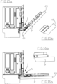
- numeral 1 indicates the hinge device for moving a decorative panel P object of the present invention.
- Device 1 comprises at least:
- the first member 3 and the second member 5 are pivoted to each other by means of a hinge pin 7 coaxial with the fulcrum or with the hinge axis of the device 1 itself.
- the first member 3 is assigned to be fixed to the frame, or structure, or body of a household appliance, for example an oven or a dishwasher, while the second member 5 is assigned to be fixed to a door of the same household appliance to hinge the door to the frame; for example, the first member 3 and the second member 5 are fixed on an external side of the frame and of the door, respectively.
- a household appliance for example an oven or a dishwasher
- the second member 5 is assigned to be fixed to a door of the same household appliance to hinge the door to the frame; for example, the first member 3 and the second member 5 are fixed on an external side of the frame and of the door, respectively.
- the device 1 can also be applied and used as a hinge for furniture, household appliance and the like, provided they are equipped with a frame and at least one door.
- the first member 3 and the second member 5 can therefore rotate with respect to each other around the hinge axis between a closed condition C of the device 1, in which the door of the household appliance blocks an opening of an internal volume of the appliance itself lying almost parallel to the plane defined by the edge of the opening, and a maximum opening condition A of the device 1, in which the door forms a maximum opening angle with such plane, for example an angle of approximately 90°.
- the joint member 13, during the rotation of the device 1 between said closed C and maximum opening A conditions, is assigned to move the decorative panel P which is constrained to translate parallel to the door of the appliance as better specified below.
- the elastic member 9 interacts, by means of the transmission elements 11, between the first member 3 and the second member 5 to impart to the latter, and therefore to the door of the appliance, an elastic closing force.
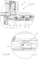
- a first end of the rocker element 15 is pivoted, by means of a first pin 14, to the joint member 13; the second and opposite end of the rocker element 15 bears a sliding pin 17.
- the median portion of the rocker element 15, located between the two ends thereof, is pivoted by means of a third pin 25 to a first end of an arm element 27 rotatable along a geometric arc of circumference centered in the hinge pin 7, being the opposite second end of the arm element 27 itself rotatably engaged or pivoted to the hinge pin 7.
- the sliding pin 17 is mobile and slidingly constrained in a shaped slot 19 which is obtained in the connection member 21 through the thickness of the latter, or which is fixed on the surface of the latter.
- the sliding pin 17 is preferably provided with a rolling means, for example a bushing or a bearing, and the edges of the shaped slot 19 are provided with an edge protruding perpendicularly to the main face of the connection member 21 to facilitate the movement of the rolling means in the shaped slot itself.
- a rolling means for example a bushing or a bearing
- the sliding pin 17 can optionally be provided with a roller or a coating which facilitates its sliding along the respective shaped slot 19, or on the contrary which hinders and slows down its sliding, thus acting as a damper for the device 1.
- connection member 21 has a connection element 35 by means of which it is directly or indirectly connected to the elastic member 9, and is also pivoted to the second member 5 by means of a second pin 23 at a point separate from the hinge pin 7, that is the second pin 23 and the hinge pin 7 have parallel but not coincident axes.
- the distance between the hinge pin 7 and the second pin 23 which connects the second member 5 and the connection member 21 is preferably less than the distance between such hinge pin 7 and the third pin 25 which connects the rocker element 15 and the arm element 27.
- Both the second pin 23 and the third pin 25 are constrained to travel along respective circular trajectories centered in the hinge pin 7 and perpendicular to the hinge axis.
- connection member 21 is an almost flat slab or plate shaped in such a way that its shape preferably has angles approximately defined by one end of the shaped slot 19, by the second pin 23 and by the connection element 35.
- the device 1 also comprises a guide element 31 sliding along walls 33 of the first member 3 parallel to the straight action line R of the elastic member 9.
- the guide element 31 is transversally constrained between the walls 33 and slides longitudinally between them between a minimum position, in which it is located near one end of the first member 3 and at the maximum distance from the hinge pin 7, and a maximum position, in which it is at the minimum distance from the hinge pin 7.
- Such guide element 31 has opposite portions which are respectively fixed to the elastic member 9 and, by means of the connection element 35, to the connection member 21 at a connection portion 22 of the latter.
- connection member 21 is therefore connected to the elastic member 9 by means of the guide element 31.
- the connection portion 22 constitutes a vertex of the connection member 21 opposite the vertex of the second pin 23 with respect to a straight line which joins the ends of the shaped slot 19.
- the guide element 31 has two further opposite portions for the sliding abutment of the walls 33 by means of respective skids 37 fixed to such portions.
- the walls 33 protrude almost perpendicularly from the main development surface of the first member 3 and constitute a track for the sliding of the guide element 31.
- the elastic member 9 is preferably a spring 41 of the helical type having one end blocked to the first member 3.
- Such spring 41 operates in compression and is provided with an internal spring guide 39, which has one end constrained to the spring 41, and is hooked at the other end to the respective portion of the guide element 31.
- the elastic member 9 can consist for example of a gas spring, comprising a cylinder blocked to the first member 3 and within which a piston slides externally hooked to the guide element 31.
- the coupling between the spring guide 39 and the guide element 31 is achieved for example by coupling a tooth, hook or shaped hook of the guide element 31 with a slotted abutment obtained in the corresponding end of the spring guide 39.
- the first member 3 preferably has a stop pin 24 of the connection member 21, fixed in the proximity of the hinge pin 7 and which, in the maximum opening condition A, is assigned to abut against the edge of the connection member 21 opposite the connection portion 22 of this, possibly in correspondence with a recess formed in such edge, to stop the movement of the connection member 21 itself and, consequently, to limit the movement of the guide element 31 along the action line R.
- the guide element 31 is hooked directly to one end of a spring 41 operating in traction and fixed at the opposite end to a suitable grip extension of the first member 3.
- connection element 35 is for example a connection pin fixed between the connection member 21 and the portion of the guide element 31 opposite the portion thereof connected to the spring 41 or to the spring guide 39.
- connection element 35 consists for example of a tooth, hook or other abutment made or fixed along an edge of the connection member 21 for direct hooking to the respective end of the spring 41 or the spring guide 39.
- the straight line joining the ends of the shaped slot 19 forms, with the straight line joining the second pin 23 and the connection element 35, an angle between 40°-120°, preferably between 65°-80°.
- such shaped slot 19 is approximately shaped as an arch of circumference with concavity facing the hinge pin 7 and with the corresponding convexity facing in the opposite direction towards the connection element 35, that is towards the connection portion 22.
- the decorative panel P is connected to the respective door of the appliance by means of sliding connection members of known type, for example guide and slide, or rail and carriage, or slot and pin.
- sliding connection members of known type, for example guide and slide, or rail and carriage, or slot and pin.
- Each side portion of the decorative panel P and not far from its P bottom edge 44 in the closed condition, is connected to the joint member 13 of the corresponding hinge device 1 of the door.
- Each constraint member is parallel to the external surface of the door and perpendicular to the hinge axis of the device 1, and therefore constrains the decorative panel P to slide parallel to the door and perpendicular to the hinge pin 7 and the devices, or at least one of them, operates the decorative panel along such sliding direction.
- the first pin 14 can be of the fixed type and blocked to the rocker element 15 and to the joint member 13 during production or, preferably, it can be of the pluggable type and applicable manually (with the fingers or with a manual tool) to the respective seats formed in the rocker element 15 and in the joint member 13.
- the first pin 14 of the manually applicable type facilitates the installation operations of the panel: it is in fact possible to fix or screw to the hidden face of the latter P, for example, with the aid of a template, the joint members 13 of the hinge devices of the door, constrain the latter to the panel by means of the constraint members and only at this point connect the joint members 13 to the respective rocker elements 15 by manually inserting the first pins 14.
- the first pins are provided with means which prevent them from slipping out from their respective seats.
- the first pin 14 or the end of the rocker element 15 which bears the first pin are constrained by a slot, a guide or the like, to slide along the second member 5 parallel to the constraint members where present.
- the operation of the device 1 applied to a household appliance equipped with a decorative panel P provides that, starting from the closed condition C, a user of the household appliance applies an opening force to the opening edge 45 of the decorative panel P itself and/or to the door of the appliance.
- the closed condition C In the closed condition C:
- the hinge angle increases, the second pin 23 rotates around the hinge pin 7 pulling the respective vertex of the connection member 21, which in turn pulls the guide element 31 by means of the connection element 35 along the walls 33, with the elastic member 9 increasing the elastic force provided.
- the combination of the motions of the second pin 23 and of the connection element 35 produces a roto-translation of the connection member 21 and an increase in the inclination angle of the shaped slot 19.
- the roto-translation of the shaped slot 19 itself sets the sliding pin 17 in motion together with the respective end of the rocker element 15 connected to it 17.
- the third pin 25 acts as a fulcrum, movable along a circumference arc determined by the arm element 27, for the rocker element 15.
- the end, carrying the joint member 13, of the rocker element 15 of each device cooperates with the constraint members in imposing predetermined motion and trajectory on the joint member 13 itself.
- the constraint members establish the trajectory that is the direction of translation of the decorative panel P along the respective door and the device determines the motion of the panel along such trajectory.
- said trajectory of the joint member 13 has an angular component which follows the course of the hinge angle and a radial component which is a function of the angular component, being predetermined and imposed by the shape and mutual constraints of the transmission elements 11.
- the appliance door remains blocked on the second member 5, while its decorative panel P, in addition to having changed its own angular orientation together with the door according to the hinge angle, has undergone a variation also in the radial component with respect to the door itself and with respect to the hinge pin 7, from which it moved away.
- the closure operation of the device 1 requires the user to apply a closing force to the opening edge 45 of the decorative panel P itself and/or to the door of the appliance, in the opposite direction to the opening force.
- the interconnected components of the device 1 follow backwards the complex motions already described above for the opening movement of the door of the household appliance.
Landscapes
- Engineering & Computer Science (AREA)
- Mechanical Engineering (AREA)
- Chemical & Material Sciences (AREA)
- Combustion & Propulsion (AREA)
- Physics & Mathematics (AREA)
- Thermal Sciences (AREA)
- General Engineering & Computer Science (AREA)
- Hinges (AREA)
Claims (10)
- Scharniervorrichtung zum Bewegen eines dekorativen Paneels (P) und umfassend ein erstes Element (3), das an einem zweiten Element (5) mittels eines Scharnierstifts (7) und eines elastischen Elements (9) angelenkt ist; wobei das erste Element (3) vorgesehen ist, um an den Rahmen oder Körper einer Anwendung befestigt zu werden und das zweite Element (5) ist vorgesehen, um an einer Tür der gleichen Anwendung befestigt zu werden; wobei das elastische Element (9) mit dem ersten Element (3) verbunden ist und zwischen dem Letzteren und dem zweiten Element (5) mittels Übertragungselementen (11) interagiert, um eine schließende Federkraft auf das zweite Element (5) auszuüben, wobei das dekorative Paneel (P) durch Verbindungsbegrenzungselemente der Tür und dem Paneel (P) eingeschränkt ist, um parallel zu der Tür und senkrecht zu dem Scharnierstift (7) zu gleiten; wobei die Vorrichtung (1) ein Gelenkelement (13) für das dekorative Paneel (P) umfasst und vorgesehen ist, Letzteres (P) entlang der Begrenzungselemente zu bewegen; in mindestens einem Betriebszustand der Vorrichtung (1) ist das Gelenkelement (13) mittels eines ersten Stifts (14) an einem ersten Ende eines Schwingelements (15) angelenkt, dessen gegenüberliegendes Ende einen Gleitstift (17) aufweist, der in einem ausgeformten Schlitz (19) bewegbar ist, wobei ein Verbindungselement (21) mittels eines zweiten Stifts (23) an einer Stelle separat von dem Scharnierstift (7) zu dem zweiten Element geschwenkt ist; ein solches Verbindungselement (21) ist mit dem Federelement (9) mittels eines Verbindungselements (35) der Übertragungselemente (11) verbunden; der mittlere Bereich des Schwingelements (15) ist mittels eines dritten Stifts (25) zu einem ersten Ende eines Armelements (27) geschwenkt, dessen gegenüberliegendes zweites Ende drehbar in den Scharnierstift (7) eingreift, wobei in einem Installationszustand der Vorrichtung (1) und des Paneels (P) die Position, die Maßverhältnisse und die Verbindung des zweiten Elements (5), des Schwingelements (15), des Verbindungselements (21) und des Armelements (27) und die Form und Ausrichtung des ausgeformten Schlitzes (19) in Zusammenarbeit mit den Begrenzungselementen auf das Gelenkelement (13) eine Bewegung parallel zu der Tür, weg von dem Scharnierstift (7) und in Übereinstimmung mit der Betätigung der Vorrichtung (1) hin zu einem maximalen Öffnungszustand (A) davon ausübt, und sich dem Scharnierstift (7) in Übereinstimmung mit der Betätigung der Vorrichtung (1) hin zu ihrem geschlossenen Zustand (C) nähert, wobei die Vorrichtung dadurch gekennzeichnet ist, dass der ausgeformte Schlitz (19) an dem Verbindungselement (21) der Übertragungselemente (11) befestigt ist oder darin ausgebildet ist.
- Vorrichtung gemäß Anspruch 1, dadurch gekennzeichnet, dass die ein Führungselement (31) umfasst, das entlang von Wänden (33) des ersten Elements (3) parallel zu der Betätigungslinie (R) des elastischen Elements (9) gleitet und gegenüberliegende Bereiche umfasst, die jeweils an dem elastischen Element (9) und mittels des Verbindungselements (35) an einem Verbindungsbereich (22) des Verbindungselements (21) gegenüber des zweiten Stifts (23) bezogen auf eine Linie, die die Enden des ausgeformten Schlitzes (19) verbindet, befestigt sind.
- Vorrichtung gemäß Anspruch 2, dadurch gekennzeichnet, dass das Führungselement (31) mittels entsprechender Kufen (37) gleitend an den Wänden (33) anstößt.
- Vorrichtung gemäß Anspruch 2 oder 3, dadurch gekennzeichnet, dass das Führungselement (31) in ein Ende einer Federführung (39) einer komprimierten Feder (41) des elastischen Elements (9) eingehakt ist und ein Ende davon zu dem ersten Element (3) geblockt ist, oder das Führungselement (31) ist an einem Ende einer Feder (41) eingehakt, die durch Zugkraft agiert, deren gegenüberliegendes Ende an einer Verlängerung des ersten Elements (3) befestigt ist.
- Vorrichtung gemäß einem der vorhergehenden Ansprüche, dadurch gekennzeichnet, dass der ausgeformte Schlitz (19) annähernd eine Kreisbogenform mit einer dem Scharnierstift (7) zugewandten Konkavität aufweist.
- Vorrichtung gemäß einem der vorhergehenden Ansprüche, dadurch gekennzeichnet, dass die Linie, die die Enden des ausgeformten Schlitzes (19) verbindet, mit der Linie, die den zweiten Stift (23) und das Verbindungselement (35) verbindet, einen Winkel zwischen 40° und 120° bildet.
- Vorrichtung gemäß einem der vorhergehenden Ansprüche, dadurch gekennzeichnet, dass der Abstand zwischen dem Scharnierstift (7) und dem zweiten Stift (23) geringer ist als der Abstand zwischen dem Scharnierstift (7) und dem dritten Stift (25).
- Vorrichtung gemäß einem der vorhergehenden Ansprüche, dadurch gekennzeichnet, dass die Form des Verbindungselements (21) annähernd dreieckig ist, wobei die Spitzen in etwa durch ein Ende des geformten Schlitzes (19), durch den zweiten Schlitz (23) und durch das Verbindungselement (35) definiert sind.
- Vorrichtung gemäß einem der vorhergehenden Ansprüche, dadurch gekennzeichnet, dass der erste Stift (14) einer der festen Art ist oder manuell eingesetzt werden kann.
- Vorrichtung gemäß einem der vorhergehenden Ansprüche, dadurch gekennzeichnet, dass der gleitende Stift (17) mit Rollmitteln versehen ist und die Kanten des geformten Schlitzes (19) mit einem Rand versehen sind, um die Bewegung der Rollmittel zu vereinfachen.
Applications Claiming Priority (1)
| Application Number | Priority Date | Filing Date | Title |
|---|---|---|---|
| IT202200014662 | 2022-07-12 |
Publications (3)
| Publication Number | Publication Date |
|---|---|
| EP4306752A1 EP4306752A1 (de) | 2024-01-17 |
| EP4306752C0 EP4306752C0 (de) | 2025-03-26 |
| EP4306752B1 true EP4306752B1 (de) | 2025-03-26 |
Family
ID=83271588
Family Applications (1)
| Application Number | Title | Priority Date | Filing Date |
|---|---|---|---|
| EP23184702.1A Active EP4306752B1 (de) | 2022-07-12 | 2023-07-11 | Scharniervorrichtung zum bewegen einer zierplatte |
Country Status (2)
| Country | Link |
|---|---|
| EP (1) | EP4306752B1 (de) |
| PL (1) | PL4306752T3 (de) |
Families Citing this family (1)
| Publication number | Priority date | Publication date | Assignee | Title |
|---|---|---|---|---|
| EP4660406A3 (de) * | 2022-11-25 | 2026-02-25 | BSH Hausgeräte GmbH | Scharnier für eine vorrichtung, insbesondere für ein haushaltsgerät oder ein mobelstück, sowie vorrichtung, insbesondere haushaltsgerät oder mobelstück |
Family Cites Families (2)
| Publication number | Priority date | Publication date | Assignee | Title |
|---|---|---|---|---|
| PL2407723T3 (pl) * | 2010-07-14 | 2018-03-30 | Electrolux Home Products Corporation N.V. | Zawias przesuwny do urządzenia gospodarstwa domowego |
| ITUA20161650A1 (it) * | 2016-03-14 | 2017-09-14 | Nuova Star Spa | Cerniera per ante di elettrodomestici. |
-
2023
- 2023-07-11 EP EP23184702.1A patent/EP4306752B1/de active Active
- 2023-07-11 PL PL23184702.1T patent/PL4306752T3/pl unknown
Also Published As
| Publication number | Publication date |
|---|---|
| EP4306752C0 (de) | 2025-03-26 |
| EP4306752A1 (de) | 2024-01-17 |
| PL4306752T3 (pl) | 2025-05-26 |
Similar Documents
| Publication | Publication Date | Title |
|---|---|---|
| US8226180B2 (en) | Door coupling system | |
| US8919338B2 (en) | Sliding and tilting door assembly | |
| US7934290B2 (en) | Door hinge device with fulcrum at variable position | |
| US8510991B2 (en) | French door hinge system for oven | |
| US9095214B2 (en) | Door closure mechanism for refrigerator or other appliance | |
| CA1091113A (en) | Oven hinge mechanism including cam balance modifier | |
| US20040093693A1 (en) | Hinge | |
| EP3014039B1 (de) | Scharniervorrichtung mit einer translationsbeschichtungsplatte | |
| EP4306752B1 (de) | Scharniervorrichtung zum bewegen einer zierplatte | |
| CA3072805A1 (en) | Self seating fenestration hardware | |
| CN218092548U (zh) | 微波炉的联锁装置和微波炉 | |
| CN110678114B (zh) | 用于家用电器的铰链 | |
| WO2019211435A1 (en) | Hinge device for refrigerator and furnishings | |
| US20240011348A1 (en) | Fenestration unit with accessible ig space | |
| EP2952664B1 (de) | Scharnier mit einem verriegelungselement | |
| KR20240113549A (ko) | 힌지 | |
| CN212249626U (zh) | 铰接装置和窗户 | |
| CN211144127U (zh) | 一种阻尼可调式的二段力铰链 | |
| CN219864634U (zh) | 双门同步开合联动结构及采用该结构的自动双开门烤箱 | |
| EP4180598B1 (de) | Scharnier und elektrische vorrichtung | |
| CN120153158A (zh) | 可配置的铰链装置 | |
| CN104420762A (zh) | 欧标c槽口隐藏式铰链平开上悬五金系统 | |
| EP3969708B1 (de) | Kompakte und gedämpfte scharniervorrichtung | |
| CN219365751U (zh) | 一种具有折叠式铰链结构的平行窗体结构 | |
| CN215421045U (zh) | 家用电器 |
Legal Events
| Date | Code | Title | Description |
|---|---|---|---|
| PUAI | Public reference made under article 153(3) epc to a published international application that has entered the european phase |
Free format text: ORIGINAL CODE: 0009012 |
|
| STAA | Information on the status of an ep patent application or granted ep patent |
Free format text: STATUS: THE APPLICATION HAS BEEN PUBLISHED |
|
| AK | Designated contracting states |
Kind code of ref document: A1 Designated state(s): AL AT BE BG CH CY CZ DE DK EE ES FI FR GB GR HR HU IE IS IT LI LT LU LV MC ME MK MT NL NO PL PT RO RS SE SI SK SM TR |
|
| STAA | Information on the status of an ep patent application or granted ep patent |
Free format text: STATUS: REQUEST FOR EXAMINATION WAS MADE |
|
| 17P | Request for examination filed |
Effective date: 20240715 |
|
| RBV | Designated contracting states (corrected) |
Designated state(s): AL AT BE BG CH CY CZ DE DK EE ES FI FR GB GR HR HU IE IS IT LI LT LU LV MC ME MK MT NL NO PL PT RO RS SE SI SK SM TR |
|
| RIN1 | Information on inventor provided before grant (corrected) |
Inventor name: TROTTA, LEONARDO TROTTA Inventor name: PIZZI, FEDERICO Inventor name: TERENZI, EMANUELE |
|
| GRAP | Despatch of communication of intention to grant a patent |
Free format text: ORIGINAL CODE: EPIDOSNIGR1 |
|
| STAA | Information on the status of an ep patent application or granted ep patent |
Free format text: STATUS: GRANT OF PATENT IS INTENDED |
|
| RIC1 | Information provided on ipc code assigned before grant |
Ipc: F25D 23/02 20060101ALI20241018BHEP Ipc: E05F 1/12 20060101ALI20241018BHEP Ipc: E05D 15/58 20060101ALI20241018BHEP Ipc: E05D 11/00 20060101ALI20241018BHEP Ipc: A47L 15/42 20060101ALI20241018BHEP Ipc: E05D 3/02 20060101AFI20241018BHEP |
|
| INTG | Intention to grant announced |
Effective date: 20241118 |
|
| GRAS | Grant fee paid |
Free format text: ORIGINAL CODE: EPIDOSNIGR3 |
|
| GRAA | (expected) grant |
Free format text: ORIGINAL CODE: 0009210 |
|
| STAA | Information on the status of an ep patent application or granted ep patent |
Free format text: STATUS: THE PATENT HAS BEEN GRANTED |
|
| AK | Designated contracting states |
Kind code of ref document: B1 Designated state(s): AL AT BE BG CH CY CZ DE DK EE ES FI FR GB GR HR HU IE IS IT LI LT LU LV MC ME MK MT NL NO PL PT RO RS SE SI SK SM TR |
|
| REG | Reference to a national code |
Ref country code: GB Ref legal event code: FG4D |
|
| REG | Reference to a national code |
Ref country code: CH Ref legal event code: EP |
|
| REG | Reference to a national code |
Ref country code: DE Ref legal event code: R096 Ref document number: 602023002564 Country of ref document: DE |
|
| REG | Reference to a national code |
Ref country code: IE Ref legal event code: FG4D |
|
| U01 | Request for unitary effect filed |
Effective date: 20250407 |
|
| U07 | Unitary effect registered |
Designated state(s): AT BE BG DE DK EE FI FR IT LT LU LV MT NL PT RO SE SI Effective date: 20250414 |
|
| PG25 | Lapsed in a contracting state [announced via postgrant information from national office to epo] |
Ref country code: RS Free format text: LAPSE BECAUSE OF FAILURE TO SUBMIT A TRANSLATION OF THE DESCRIPTION OR TO PAY THE FEE WITHIN THE PRESCRIBED TIME-LIMIT Effective date: 20250626 |
|
| PG25 | Lapsed in a contracting state [announced via postgrant information from national office to epo] |
Ref country code: NO Free format text: LAPSE BECAUSE OF FAILURE TO SUBMIT A TRANSLATION OF THE DESCRIPTION OR TO PAY THE FEE WITHIN THE PRESCRIBED TIME-LIMIT Effective date: 20250626 |
|
| PG25 | Lapsed in a contracting state [announced via postgrant information from national office to epo] |
Ref country code: HR Free format text: LAPSE BECAUSE OF FAILURE TO SUBMIT A TRANSLATION OF THE DESCRIPTION OR TO PAY THE FEE WITHIN THE PRESCRIBED TIME-LIMIT Effective date: 20250326 |
|
| PG25 | Lapsed in a contracting state [announced via postgrant information from national office to epo] |
Ref country code: GR Free format text: LAPSE BECAUSE OF FAILURE TO SUBMIT A TRANSLATION OF THE DESCRIPTION OR TO PAY THE FEE WITHIN THE PRESCRIBED TIME-LIMIT Effective date: 20250627 |
|
| U20 | Renewal fee for the european patent with unitary effect paid |
Year of fee payment: 3 Effective date: 20250731 |
|
| PG25 | Lapsed in a contracting state [announced via postgrant information from national office to epo] |
Ref country code: SM Free format text: LAPSE BECAUSE OF FAILURE TO SUBMIT A TRANSLATION OF THE DESCRIPTION OR TO PAY THE FEE WITHIN THE PRESCRIBED TIME-LIMIT Effective date: 20250326 |
|
| PG25 | Lapsed in a contracting state [announced via postgrant information from national office to epo] |
Ref country code: ES Free format text: LAPSE BECAUSE OF FAILURE TO SUBMIT A TRANSLATION OF THE DESCRIPTION OR TO PAY THE FEE WITHIN THE PRESCRIBED TIME-LIMIT Effective date: 20250326 |
|
| PGFP | Annual fee paid to national office [announced via postgrant information from national office to epo] |
Ref country code: TR Payment date: 20250718 Year of fee payment: 3 Ref country code: PL Payment date: 20250723 Year of fee payment: 3 |
|
| PG25 | Lapsed in a contracting state [announced via postgrant information from national office to epo] |
Ref country code: SK Free format text: LAPSE BECAUSE OF FAILURE TO SUBMIT A TRANSLATION OF THE DESCRIPTION OR TO PAY THE FEE WITHIN THE PRESCRIBED TIME-LIMIT Effective date: 20250326 |
|
| PG25 | Lapsed in a contracting state [announced via postgrant information from national office to epo] |
Ref country code: IS Free format text: LAPSE BECAUSE OF FAILURE TO SUBMIT A TRANSLATION OF THE DESCRIPTION OR TO PAY THE FEE WITHIN THE PRESCRIBED TIME-LIMIT Effective date: 20250726 |
|
| PG25 | Lapsed in a contracting state [announced via postgrant information from national office to epo] |
Ref country code: CZ Free format text: LAPSE BECAUSE OF FAILURE TO SUBMIT A TRANSLATION OF THE DESCRIPTION OR TO PAY THE FEE WITHIN THE PRESCRIBED TIME-LIMIT Effective date: 20250326 |
|
| PLBE | No opposition filed within time limit |
Free format text: ORIGINAL CODE: 0009261 |
|
| STAA | Information on the status of an ep patent application or granted ep patent |
Free format text: STATUS: NO OPPOSITION FILED WITHIN TIME LIMIT |
|
| REG | Reference to a national code |
Ref country code: CH Ref legal event code: L10 Free format text: ST27 STATUS EVENT CODE: U-0-0-L10-L00 (AS PROVIDED BY THE NATIONAL OFFICE) Effective date: 20260211 |