EP4306734B1 - Brandschutzisolierung - Google Patents
Brandschutzisolierung Download PDFInfo
- Publication number
- EP4306734B1 EP4306734B1 EP23173568.9A EP23173568A EP4306734B1 EP 4306734 B1 EP4306734 B1 EP 4306734B1 EP 23173568 A EP23173568 A EP 23173568A EP 4306734 B1 EP4306734 B1 EP 4306734B1
- Authority
- EP
- European Patent Office
- Prior art keywords
- insulation
- fire
- metal wall
- insulation material
- insulating
- Prior art date
- Legal status (The legal status is an assumption and is not a legal conclusion. Google has not performed a legal analysis and makes no representation as to the accuracy of the status listed.)
- Active
Links
Images



Classifications
-
- B—PERFORMING OPERATIONS; TRANSPORTING
- B63—SHIPS OR OTHER WATERBORNE VESSELS; RELATED EQUIPMENT
- B63B—SHIPS OR OTHER WATERBORNE VESSELS; EQUIPMENT FOR SHIPPING
- B63B43/00—Improving safety of vessels, e.g. damage control, not otherwise provided for
-
- B—PERFORMING OPERATIONS; TRANSPORTING
- B63—SHIPS OR OTHER WATERBORNE VESSELS; RELATED EQUIPMENT
- B63B—SHIPS OR OTHER WATERBORNE VESSELS; EQUIPMENT FOR SHIPPING
- B63B3/00—Hulls characterised by their structure or component parts
- B63B3/14—Hull parts
- B63B3/68—Panellings; Linings, e.g. for insulating purposes
-
- F—MECHANICAL ENGINEERING; LIGHTING; HEATING; WEAPONS; BLASTING
- F16—ENGINEERING ELEMENTS AND UNITS; GENERAL MEASURES FOR PRODUCING AND MAINTAINING EFFECTIVE FUNCTIONING OF MACHINES OR INSTALLATIONS; THERMAL INSULATION IN GENERAL
- F16L—PIPES; JOINTS OR FITTINGS FOR PIPES; SUPPORTS FOR PIPES, CABLES OR PROTECTIVE TUBING; MEANS FOR THERMAL INSULATION IN GENERAL
- F16L59/00—Thermal insulation in general
- F16L59/02—Shape or form of insulating materials, with or without coverings integral with the insulating materials
- F16L59/028—Compositions for or methods of fixing a thermally insulating material
-
- F—MECHANICAL ENGINEERING; LIGHTING; HEATING; WEAPONS; BLASTING
- F16—ENGINEERING ELEMENTS AND UNITS; GENERAL MEASURES FOR PRODUCING AND MAINTAINING EFFECTIVE FUNCTIONING OF MACHINES OR INSTALLATIONS; THERMAL INSULATION IN GENERAL
- F16L—PIPES; JOINTS OR FITTINGS FOR PIPES; SUPPORTS FOR PIPES, CABLES OR PROTECTIVE TUBING; MEANS FOR THERMAL INSULATION IN GENERAL
- F16L59/00—Thermal insulation in general
- F16L59/02—Shape or form of insulating materials, with or without coverings integral with the insulating materials
- F16L59/026—Mattresses, mats, blankets or the like
-
- F—MECHANICAL ENGINEERING; LIGHTING; HEATING; WEAPONS; BLASTING
- F16—ENGINEERING ELEMENTS AND UNITS; GENERAL MEASURES FOR PRODUCING AND MAINTAINING EFFECTIVE FUNCTIONING OF MACHINES OR INSTALLATIONS; THERMAL INSULATION IN GENERAL
- F16L—PIPES; JOINTS OR FITTINGS FOR PIPES; SUPPORTS FOR PIPES, CABLES OR PROTECTIVE TUBING; MEANS FOR THERMAL INSULATION IN GENERAL
- F16L59/00—Thermal insulation in general
- F16L59/02—Shape or form of insulating materials, with or without coverings integral with the insulating materials
- F16L59/029—Shape or form of insulating materials, with or without coverings integral with the insulating materials layered
-
- F—MECHANICAL ENGINEERING; LIGHTING; HEATING; WEAPONS; BLASTING
- F16—ENGINEERING ELEMENTS AND UNITS; GENERAL MEASURES FOR PRODUCING AND MAINTAINING EFFECTIVE FUNCTIONING OF MACHINES OR INSTALLATIONS; THERMAL INSULATION IN GENERAL
- F16L—PIPES; JOINTS OR FITTINGS FOR PIPES; SUPPORTS FOR PIPES, CABLES OR PROTECTIVE TUBING; MEANS FOR THERMAL INSULATION IN GENERAL
- F16L59/00—Thermal insulation in general
- F16L59/04—Arrangements using dry fillers, e.g. using slag wool
Definitions
- the invention relates to fire protection insulation for use on a ship, comprising a metal wall, metal insulation needles that are attached to the metal wall and are aligned essentially perpendicularly to it, insulation material that is placed on the insulation needles so that the insulation material is held to the metal wall.
- the fire protection insulation is used in particular for insulating ship's sides, decks and bulkheads, with bulkhead insulation A60 and A120 being installed vertically and deck insulation A60 being installed horizontally in the ship.
- Fire insulation is used on ships to limit the impact of fires on board in terms of space and time.
- the walls of a ship, including bulkheads are provided with fire insulation.
- This usually includes a type of fastening and insulating material held to the fastening.
- the insulating material has a low thermal conductivity coefficient and high heat resistance.
- the lining of rooms that are important for the survival of the crew and/or the technical integrity or stability of the ship.
- the insulating material serves to achieve the fire protection effect through fire insulation.
- engine rooms are provided with insulating material on the walls or bulkheads including ceilings. A fire in the engine room then does not spread to other rooms or only spreads after a delay due to the fire insulation.
- the DE 10 2004 006 321 A1 presents a fireproof wall.
- the fireproof wall consists of two spaced wall elements. Between the wall elements there is an intermediate layer made of a non-metallic material. In addition, the gaps are filled with fireproof material. The aim of this arrangement is to provide a fireproof wall that is lighter and therefore more cost-effective.
- the CN 107 178 682 A describes a composite structure for thermally insulating a high temperature pipeline against radiation.
- the composite structure comprises an upper and a lower semicircular structure with a layer of insulating material and a closed air layer and a nail device that fixes the shape.
- the semicircular structures envelop the pipeline and are held together by connecting structures on the left and right sides of the pipeline. Also from document CN110588886 State-of-the-art fire protection insulation is known.
- the invention is based on the object of creating a fire protection insulation which has both fire protection and a high mechanical resistance.
- the metal wall is a plate (also referred to as "sheet metal"), which can be flat and/or curved.
- the metal wall can have stiffening profiles.
- the metal wall represents in particular a deck or a bulkhead. However, it can also be part of the outer shell, in particular a floor or side wall.
- Insulating needles are elongated fastening means which are made of metal and are attached to the metal wall in such a way that they extend essentially perpendicularly away from the wall.
- Essentially perpendicular refers to orientations of the insulating needles which are aligned perpendicular to the wall and orientations which deviate from the vertical and allow the insulation material to be attached to the insulating needles.
- the insulating needles can have a cylindrical shape with a circular cross-section, but are not limited to this. Triangular or other polygonal cross-sections can also be used.
- the insulating pins are used to attach the insulation material.
- the insulating material is placed on the insulating pins.
- the insulating material is usually made of fibrous or foamed material with a relatively low density.
- the insulating material consists of stone, glass or ceramic fibers, for example. The insulating material is often not dimensionally stable.
- the insulating material is fire-resistant and has a low thermal conductivity. It therefore protects the insulated rooms from the effects of a fire. Because the insulating material is placed on the insulating pins, it is held in as constant a position as possible relative to the wall, even when the ship is moving. It should be noted that the insulating pins preferably have a length that is based on the thickness of the insulating material, so that the appearance of the wall is not disturbed and the risk of injury from protruding insulating pins is reduced.
- the fire protection insulation according to the invention has insulating pins that have a diameter that is less than or equal to 3 mm and which have reinforcement in the area of the attachment to the metal wall.
- the choice of a maximum diameter of 3 mm means that the cross-section of the insulation needles is relatively small compared to the area of the insulation material. This means that little heat is conducted through the insulation needles in the event of a fire. In addition, this relatively small cross-section saves material compared to larger cross-sections, resulting in cost and weight advantages.
- the diameter of the insulation needles is the equivalent diameter of the cross-section of the insulation needles. The equivalent diameter is derived from the area of the cross-section via the relationship between the squared radius, the number pi and the area of a circle. For circular cross-sections, the diameter corresponds to the diameter of the cross-section.
- the reinforcement in the area of the attachment ensures that there is high mechanical resistance.
- the reinforcement in the area of the attachment greatly increases shock resistance without the needle diameter having to be increased.
- the reinforcement is preferably dimensioned and positioned in such a way that, under normal shock conditions, which are simulated, for example, by a standardized test, it absorbs mechanical forces acting on the insulating needles without causing the insulating needles to fail.
- a bushing can be used as reinforcement, which is pressed onto the lower part of the insulating needle.
- other manufacturing processes than joining additional components can also be used.
- Additional material can be welded on using a primary forming process, for example; the needle can be compressed in the area of the attachment using a forming process, the insulating needles can be milled or turned to the desired diameter using a separation process, for example from a larger blank, so that the original additional material of the blank is only present in the area of the reinforcement, a high-strength metal layer can be applied using a coating process, and/or an area of the insulating needle can be hardened using a process for changing the material properties, for example. It should therefore be noted that reinforcement can take place in a variety of ways.
- the distance between one insulation needle and the next insulation needle is equal to or less than 150 mm.
- the distance between an insulating needle and the ends or joints of the insulation material is equal to or less than 50 mm. This relatively small distance between the insulating needles ensures that in the event of a high mechanical load on the fire protection insulation, e.g. due to a shock caused by a torpedo hit, the insulation material is still held to the wall.
- the distances between the insulating needles are essentially chosen so that the heat conducted via the insulating needles remains limited in the event of a fire.
- the insulating needles are cylindrical.
- the use of cylindrical insulating needles with a circular cross-section has the advantage that the raw material can be obtained as inexpensive rod material, e.g. as wire.
- rod material can be processed more easily.
- the reinforcement is a weldable bushing pressed onto the insulating needle, which is arranged at the lower end of the insulating needle.
- Such a bushing can be purchased as a part, e.g. as a tube that is sawn off to the appropriate bushing length. For example, by heating the bushing and cooling the insulating needles in combination with a suitably selected fit, it is possible to ensure that the bushing is held securely on the insulating needle without having to use additional joining agents.
- the bushing is attached to the lower end of the insulating needle, i.e. near the attachment of the insulating needles to the metal wall.
- the clamping point here the weld with the ship's wall or the deck, when mechanical stress is applied to the fire protection insulation, particularly high loads act on the insulation needles due to the inertia of the insulation material.
- the bushing has a maximum height of 15 mm.
- the bushing is preferably dimensioned depending on the load present, for example, in a shock test.
- a maximum height of 15 mm ensures in particular that the mechanical load is absorbed without failure and that the thermal conductivity of the insulating needles is maintained as desired. Limiting the height of the bushing also saves costs and processing.
- the bushing has a maximum diameter of 7.5 mm.
- a limitation of the diameter and the associated limitation of the wall thickness has a positive effect on weight and cost savings without negatively affecting the thermal conductivity or mechanical resistance properties.
- the insulating needles have a sleeve at the point of attachment to the wall, which sleeve has a larger diameter than the reinforcement.
- a sleeve is usually thin and plate-shaped. It can be attached to the insulating needle. However, it can also be attached to the socket.
- the sleeve can be a flange or collar formed in one piece with the socket, which is produced, for example, by flanging.
- the sleeve serves to ensure that the insulating needle has a larger contact area on the metal wall, which in particular serves to positively support a joining process, such as welding.
- such a sleeve can also serve, for example, to represent an end stop for a socket used for reinforcement, which simplifies assembly.
- the insulating needles are arranged in a square grid.
- the arrangement of the insulating needles in a square grid means that the forces transmitted to the insulating needles when the fire protection insulation is subjected to mechanical stress are transmitted evenly to all insulating needles. This also makes it possible, among other things, to design the device in accordance with safety guidelines prior to installation.
- the insulating needles are attached to the metal wall by spot and/or resistance welding.
- Spot and resistance welding are common welding methods. They allow the insulating needles to be joined to the metal wall, which in particular ensures high mechanical stability. Both spot and resistance welding are easy to handle, which also offers advantages for certification.
- metal clips are clamped onto the insulating needles so that the insulating material is fixed to the metal wall.
- the use of metal clips ensures that the positioning of the insulating material on the metal wall and any other intermediate layers on the side of the insulating material facing away from the metal wall is guaranteed even in the event of a mechanical load that acts at least partially in a vertical direction relative to the metal wall.
- the metal clips are preferably designed as plates that have a substantially central hole. The plates are pushed onto the insulating needles via the hole. The clips are held on the insulating needles by a clamping effect.
- the use of several metal clips has the particular advantage that higher mechanical forces can be absorbed. In comparison to larger and/or stronger metal clips, it is still possible to use metal clips that are inexpensive to handle and purchase, while ensuring functionality that would otherwise be fulfilled by larger and/or stronger metal clips.
- three metal clips are clamped onto the insulation needle.
- the use of three metal clips is preferred because corresponding insulation material dimensions and properties were selected when designing the fire protection insulation.
- the use of fewer or more metal clips is also possible in other embodiments.
- similar metal clips can be used, so that purchasing and installation remain simplified.
- the use of insulation material with a density of approx. 50 kg/m 3 or 56 kg/m 3 in the area and approx. 56 kg/m 3 or 76 kg/m 3 in the stiffening profiles is preferred on the bulkhead.
- an insulation material density of approx. 56 kg/m 3 in the area on the deck and approx. 76 kg/m 3 in the stiffening profiles is preferred.
- the insulation material has a sufficient density to meet the necessary insulation properties. In the event of a fire, it can be guaranteed that the Fire insulation fulfils its function for a sufficiently long time and the ship is protected from further consequential damage.
- the insulation material consists of several layers. If the insulation material consists of several layers, complicated geometries of the metal wall - e.g. T-profiles - can still be protected with sufficient insulation material. Furthermore, it is also possible in such a case to use standardized formats of the insulation material. In addition, in order to meet the required fire protection duration by using several layers, it is not necessary to use insulation material with an increased density, which could lead to mechanical overloading of the insulation needles after a shock load occurs.
- the insulation material consists of two layers.
- two layers By using two layers, a wide variety of geometries can be covered that arise during the construction and design of a ship and for which the required fire protection properties must be maintained. For many designs, two layers offer a good compromise between the fire protection properties, the usable density of the insulation material and handling during production.
- the insulation material consists of one layer.
- the use of only one layer has advantageous properties, particularly during assembly and handling. By choosing an appropriate thickness of the insulation material, a sufficient fire protection effect can still be achieved.
- the insulation material on bulkheads has a thickness of approximately 100 mm or 60 mm in area and approximately 70 mm or 20 mm in stiffening profiles.
- the insulation material on the deck has a thickness of approximately 50 mm in area and approximately 20 mm in stiffening profiles.
- the choice of these thicknesses of the insulation material is able to meet typical requirements for the duration of a fire protection guarantee, as set by shipyards when building ships. By choosing different insulation material thicknesses in different areas of the ship the fire protection requirements for the respective areas are met.
- the choice of a thicker insulation material serves in particular to extend the duration of fire protection, e.g. with fire protection insulation A120 compared to fire protection insulation A60 on bulkheads.
- At least one fabric mat is arranged on the insulation material.
- One or more fabric mats can be used to make the fire protection insulation even more versatile.
- a fabric mat can be used to absorb additional forces in the event of shock or other mechanical stress. However, it also serves to prevent chemical stress, e.g. from acids, oil or water vapor that leads to corrosion.
- a fabric mat can be attached between the metal wall and the insulation material.
- a fabric mat can be arranged on the side of the insulation material facing away from the metal wall.
- a fabric mat is arranged on the insulation material on the side facing away from the metal wall.
- the use of a fabric mat on the side of the insulation material facing away from the metal wall has advantages, especially when assembling and fastening the insulation material.
- the fabric mat helps to ensure the positioning of the insulation material even when mechanical loads are applied to the fire protection insulation.
- the fabric mat is able to absorb high tensile forces, among other things.
- the fabric mat also covers the insulation material.
- the fabric mat therefore also has a positive effect on the fire protection properties because it can be made of a material that is more resistant to external influences than the insulation material, for example.
- the fabric mat can also be provided with different colors and coatings, which, for example, help to ensure an attractive aesthetic on board.
- the fabric mat is arranged between the metal clips closest to the metal wall and the insulation material.
- the metal clips on the wall and the insulation material ensure that the fabric mat is held to the insulation material by the metal clips. In the event of mechanical stress due to shock, a large part of the forces acting on the fabric mat can be transferred from the insulation material to the fabric mat and from there to the metal clips and from there to the insulation needles.
- the fabric mat is coated with aluminum foil.
- the fabric mat can be provided with an aluminum foil to further expand the diverse properties of the fabric mat.
- the aluminum foil is particularly resistant to corrosion. At the same time, it offers a high level of resistance to the effects of external influences. It also helps to protect the insulation material against the penetration of moisture.
- the aluminum foil can serve as a vapor barrier.
- the aluminum coating can be applied using conventional manufacturing processes, so that a corresponding coating can be applied easily and inexpensive production is guaranteed.
- the aluminum foil is arranged on the side facing or facing away from the metal wall.
- the positioning of the aluminum foil relative to the metal wall is carried out in accordance with the specifications used in the construction of the ship. Positioning the aluminum foil on the side facing away from the metal wall ensures that the aluminum foil is visible from the outside. To protect the insulation material from the penetration of liquid, positioning the aluminum foil on the side facing the metal wall is particularly advantageous. Furthermore, in this position, the aluminum foil protects the fabric and the insulation material against heat radiation or other radiation.
- the fabric mat is made of glass cloth.
- the use of glass cloth enables the fabric mat to absorb high forces because it is very resistant. At the same time, the use of glass cloth also enables weight savings compared to other materials.
- the fabric mat is painted on the side facing away from the metal wall.
- the aesthetics on board can be ensured in accordance with the specifications.
- a wide variety of functional coatings can also be implemented, which serve, for example, to achieve favorable non-stick properties, reduce susceptibility to corrosion or improve fire protection properties.
- one or more cover caps are placed on the metal clips.
- Cover caps can be used to cover the ends of the insulating needles that protrude from the fire protection insulation and are therefore visible and touchable. This particularly increases the aesthetics. Covering the ends of the insulating needles can also minimize the risk of injury.
- the insulation material is laid over stiffening profiles which extend essentially perpendicularly from the metal wall.
- Walls of a ship's side or bulkheads can have stiffening profiles to improve the mechanical properties. If such walls or bulkheads are nevertheless to be provided with fire protection insulation, the fire protection insulation can be laid over the stiffening profiles.
- it is particularly important to ensure that there are only very small air pockets in the area of the joints and transitions from the stiffening profile to the metal wall.
- the metal wall has at least one stiffening profile to which, as on the rest of the metal wall, insulating material is held by means of insulating needles in order to insulate the stiffening profile. If very large stiffening profiles are required to reinforce the ship's hull, these must also be provided with fire protection insulation. In such a case, the components of the fire protection insulation according to the invention are applied to the reinforcing profile, as described above for the metal wall.
- joints of the insulation material are glued with glass cloth tape. At transitions or at the end of wall sections, joints of the fire protection insulation can be visible. Such joints, where the insulation material is primarily visible, can be glued using glass cloth tape. This allows aesthetics to be maintained in accordance with the specifications. In particular, gluing the joints also ensures that the insulation material is not moved from its position on the wall as a result of mechanical forces.
- the joints of the fabric mat are bonded with glass cloth tape. Even when using a fabric mat, it may be necessary to cover the joints with glass cloth tape. As already explained above, this has particularly advantageous effects on the aesthetics and mechanical resistance of the fire protection insulation.
- the Marine Equipment Directive (MED) 2014/90/EU is applied to test the fire protection properties of the fire insulation.
- the fire insulation is designed to meet the requirements of MED 2018/773, item No. MED/3.11a. SOLAS 74 as amended, Regulation II-2/3.2 & II-2/9, IMO 2010 FTP Code, IMO MSC/Circ.1120 and IMO MSC.1/Circ.1434 and/or (EU) 2019/1397, item No. MED/3.11a.
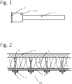
- Figure 1 shows a side view of an insulating needle 1.
- the insulating needle 1 has a cylindrical shape and a circular cross-section. It is made of metal and can be manufactured, for example, by cutting standard rod material to length.
- the insulating needle 1 has a reinforcement 12.
- the reinforcement 12 is designed as a bushing 2.
- the bushing is a hollow cylinder which is pressed onto the cylindrical insulating needle 1 at the lower end. For this purpose, the bushing 2 is heated during production and the insulating needle 1 is cooled. The bushing 2 can then be pushed onto the insulating needle 1 and from then on both components are joined together.
- the insulating needle 1 also has a sleeve 3 at the end to which the socket 2 is attached. On the side of the sleeve 3, the insulating needle 1 is connected to a (not shown) and then welded to the metal wall during the manufacture of fire protection insulation.
- the sleeve 3 facilitates the welding process. It is manufactured, for example, by flanging the bushing 2.
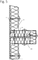
- Figure 2 shows a metal wall 4 to which a layer of insulation material 5 is held.
- a fabric mat 5 is held on the insulation material 5.
- the insulation material 5 is thicker.
- the fabric mat 6 is fixed to the insulation material 5 and this is fixed to the wall by a metal clip 7.
- the metal clip 7 is clamped onto an insulation needle 1 by a clamping effect, so that a force is transferred from the insulation material 5 to the fabric mat 6 to the metal clip 7 and the insulation needle 1 and thus also to the metal wall 4 if the fire protection insulation 100 is subjected to mechanical stress as a result of shock.
- the insulation needles 1 are welded to the metal wall 4 by resistance welding, so that forces generated by the insulation wool 5 are transferred to the metal wall 4 after a shock load.
- the insulating needles 1 are designed in such a way that they are not much longer than the combined thickness of the fabric mat 6 and the insulation material 5. In addition, the insulating needles 1 are aligned essentially perpendicularly relative to the metal wall 4. It can be seen that the insulating needles 1 have reinforcements 12. As already shown in the embodiment of the insulating needle 1 in Figure 1 , the reinforcement 12 is suitable for allowing larger forces to act on the insulating needle 1 without causing failure of the insulating needle 1.
- Shock can occur if a ship on which the fire protection insulation 100 is installed is hit by a torpedo, for example. It is shown that two metal clips 8 are used on an insulating needle. This increases the clamping force of the metal clips 8. Several insulating needles 1 are also used to distribute the transmitted forces and avoid overloading.
- the insulating material 5 is designed as insulating wool with a density of 56 kg/m 3.
- the forces acting on the insulating needles 1 due to the inertia of the insulating material when a shock load occurs are reduced by a low density of the insulating material 5. In such a case, the fabric mat 6 also takes absorbs part of the forces, thus preventing tearing or detachment from the metal wall of the insulating material 5.
- Figure 3 shows the arrangement Figure 2 from a view from above.
- the insulating needles 1 and the metal clips 7 as well as the fabric mat 6 can be seen. It is clear that the insulating needles are arranged in a square grid. During production, care must be taken to ensure that the insulating needles are spaced equal to or less than 150 mm apart.
- Figure 4 shows the fire protection insulation 100 in a sectional view from the side.
- the metal wall 4 has a stiffening profile 8.
- the stiffening profile 8 interrupts the layer of insulating material 5.
- the stiffening profile 8 is covered with a second layer of insulating material 9. This also insulates the stiffening profile 8.
- the second layer of insulating material 9 has a higher density and a lower thickness than the first layer of insulating material 5.
- a fabric mat 10 is arranged over the second layer of insulating material 9.
- the fabric mat 10 has an aluminum foil 11 on the outside, which faces away from the metal wall 4.
- the aluminum foil serves as a vapor protection and prevents moisture from penetrating the insulating material 5, 9.
- Cover caps 12 are pushed over the ends of the insulating needles 1 in order to minimize the risk of injury and to make the aesthetically pleasing.
- the joints of the fabric mat 11 and the two insulating materials 5, 9 are covered with a glass cloth bandage 13. This prevents slipping and ensures that moisture or other contamination does not penetrate.
- Figure 5 shows an arrangement in which a stiffening profile 14 is also insulated.
- the plate-shaped insulating materials 15 and the insulating needles are arranged differently on the metal walls 4, 14. Plates of the insulating material 15 lie flat on both the metal wall 14 representing a stiffening profile and on the remaining metal wall 5. In this way, the insulating material 15 can have a greater thickness than in the Figure 5 This ensures that the fire protection insulation 100 meets the fire protection requirements for a longer period of time. At the same time, however, no insulation material 15 with an increased density needs to be used. An increased
- Figure 6 represents a similar arrangement as in Figure 6
- two layers of plate-shaped insulation material 16 are used on the stiffening profile 14. This structure ensures that the necessary minimum requirements are met even at the points where the insulation material is thinnest, e.g. 70 mm on the outer areas of the cross member of the T-beam used as a stiffening profile.
Landscapes
- Engineering & Computer Science (AREA)
- Mechanical Engineering (AREA)
- Chemical & Material Sciences (AREA)
- Combustion & Propulsion (AREA)
- Ocean & Marine Engineering (AREA)
- General Engineering & Computer Science (AREA)
- Building Environments (AREA)
Description
- Die Erfindung betriff eine Brandschutzisolierung zum Einsatz auf einem Schiff umfassend eine Metallwand, aus Metall bestehende Isoliernadeln, die auf der Metallwand befestigt und im Wesentlichen zu dieser senkrecht ausgerichtet sind, Dämmmaterial, welches auf die Isoliernadeln gesteckt ist, sodass das Dämmmaterial an der Metallwand gehalten ist. Die Brandschutzisolierung kommt insbesondere zur Isolierung von Bordwänden, Decks und von Schotten zum Einsatz, wobei Schottisolierungen A60 und A120 vertikal und Deckisolierungen A60 horizontal im Schiff verbaut sind.
- Brandschutzisolierungen werden auf Schiffen dazu eingesetzt, dass die Auswirkung von Bränden an Bord räumlich und zeitlich beschränkt wird. Dazu werden Wände eines Schiffes, inklusive Schotten, mit der Brandschutzisolierung versehen. Diese umfasst in der Regel eine Art der Befestigung sowie an der Befestigung gehaltenes Dämmmaterial. Das Dämmmaterial verfügt über einen niedrigen Wärmeleitungskoeffizienten und eine hohe Hitzebeständigkeit. Das Auskleiden von Räumlichkeiten, die für das Überleben der Besetzung und/oder die technische Integrität bzw. Stabilität des Schiffes wichtig sind. Das Dämmmaterial dient dazu, die Brandschutzwirkung durch die Brandschutzisolierung zu erzielen. Beispielsweise werden Maschinenräume an den Wänden bzw. Schotten inklusive Decken mit Dämmmaterial versehen. Ein Brand im Maschinenraum greift danach aufgrund der Brandschutzisolierung nicht bzw. verzögert auf andere Räumlichkeiten über.
- Insbesondere für Schiffe, die für den militärischen Gebrauch konzipiert sind, spielt neben den Brandschutzeigenschaften einer Brandschutzisolierung auch deren mechanische Widerstandfähigkeit eine entscheidende Rolle. Nur wenn die Brandschutzisolierung ausreichende Widerstandfähigkeit gegen sogenannten Schock aufweist, kann davon ausgegangen werden, dass die Brandschutzisolierung auch nach einem Treffer z.B. durch einen Torpedo so weit in Takt bleibt, dass zuvor definierte Brandschutzanforderungen erfüllt werden. Das Einhalten der Brandschutzanforderungen nach einem Schockereignis wird durch entsprechende Schocktests sichergestellt. Bei solchen Tests erfährt eine Brandschutzisolierung eine starke Beschleunigung in x-, y- oder z-Richtung. Das Schiff definiert die Richtung: die x-Richtung verläuft vom Heck zum Bug, die y-Richtung von Steuer- nach Backbord und die z-Richtung vom Kiel zum Deck.
- Die
DE 10 2004 006 321 A1 stellt eine feuerfeste Wand vor. Die feuerfeste Wand besteht aus zwei beabstandeten Wandelementen. Zwischen den Wandelementen befindet sich eine Zwischenlage aus einem nicht-metallischen Material. Zudem sind Zwischenräume mit feuerfestem Material versehen. Mit dieser Anordnung wird das Ziel verfolgt, eine feuerfeste Wand zur Verfügung zu stellen, welche leichter und damit kostengünstiger ist. - Die
CN 107 178 682 A beschreibt eine Verbundstruktur zum Wärmeisolieren gegen Strahlung für eine Rohrleitung mit hoher Temperatur. Die Verbundstruktur umfasst eine obere und eine untere halbkreisförmige Struktur mit einer Lage aus Isoliermaterial, und einer geschlossenen Luftschicht sowie eine die Form fixierende Nagelvorrichtung. Die halbkreisförmigen Strukturen umhüllen die Rohrleitung und werden auf der linken und der rechten Seite der Rohrleitung durch Verbindungsstrukturen zusammengehalten. Auch aus DokumentCN110588886 ist eine Brandschutzisolierung nach dem Stand der Technik bekannt. - Ausgehend hiervon liegt der Erfindung die Aufgabe zugrunde, eine Brandschutzisolierung zu schaffen, welche sowohl einen Brandschutz als auch eine hohe mechanische Widerstandsfähigkeit aufweist.
- Die Aufgabe wird durch eine Brandschutzisolierung mit den Merkmalen von Anspruch 1 gelöst. Vorteilhafte Ausführungsarten der Brandschutzisolierung sind in Unteransprüchen und in der nachfolgenden Beschreibung angegeben.
- Die erfindungsgemäße Brandschutzisolierung zum Einsatz auf einem Schiff umfasst
- eine Metallwand, die ein Deck, ein Schott oder ein Teil der Außenhülle eines Schiffes ist,
- aus Metall bestehende Isoliernadeln, die auf der Metallwand befestigt sind und im Wesentlichen senkrecht zu der Metallwand ausgerichtet sind,
- plattenförmiges Dämmmaterial, welches auf die Isoliernadeln gesteckt ist, sodass das Dämmmaterial an der Metallwand gehalten wird, ist dadurch gekennzeichnet, dass
- die Isoliernadeln einen Durchmesser von kleiner oder gleich 3 mm und im Bereich der Befestigung an der Metallwand eine Verstärkung aufweisen und die Verstärkung eine mit der Isoliernadel verpresste Buchse ist, welche am unteren Ende der Isoliernadel angeordnet ist.
- Bei der erfindungsgemäßen Brandschutzisolierung wird plattenförmiges Dämmmaterial an einer Metallwand gehalten. Dazu kommen Isoliernadeln zum Einsatz. Die Metallwand ist im einfachsten Fall eine Platte (auch als "Blech" bezeichnet), die eben und/oder gekrümmt sein kann. Die Metallwand kann Versteifungsprofile aufweisen. Ferner stellt die Metallwand insbesondere ein Deck oder ein Schott dar. Sie kann aber auch Teil der Außenhülle, insbesondere einer Boden- oder Bordwand, sein. Isoliernadeln sind längliche Befestigungsmittel, welche aus Metall gefertigt sind und so an der Metallwand befestigt sind, dass sie sich im Wesentlichen senkrecht von der Wand weg erstrecken. Mit "im Wesentlichen senkrecht" sind Ausrichtungen der Isoliernadeln bezeichnet, die senkrecht zur Wand ausgerichtet sind und von der Senkrechten abweichende Ausrichtungen, die ein Aufstecken des Dämmmaterials auf die Isoliernadeln zulassen. Die Isolationsnadeln können eine zylindrische Form mit kreisrundem Querschnitt aufweisen, sind aber nicht auf eine solche beschränkt. Auch drei- oder andere mehreckige Querschnitte können verwendet werden. Die Isoliernadeln dienen dazu, das Dämmmaterial zu befestigen. Dazu ist das Dämmmaterial auf die Isoliernadeln gesteckt. Das Dämmmaterial besteht in der Regel aus faserartigem oder auch geschäumtem Material mit einer relativ geringen Dichte. Das Dämmmaterial besteht z.B. stein-, glas- oder keramischen Fasern. Häufig ist das Dämmmaterial nicht formstabil. Allerdings ist das Dämmmaterial brandbeständig und weist eine geringe Wärmeleitfähigkeit auf. Es schützt die isolierten Räume somit vor den Auswirkungen eines Feuers. Dadurch, dass das Dämmmaterial auf die Isoliernadeln gesteckt ist, wird es relativ zu der Wand auch bei einer Fahrt des Schiffs an einer möglichst gleichbleibenden Position gehalten. Es gilt dabei zu beachten, dass die Isoliernadeln vorzugsweise eine Länge aufweisen, die sich an der Dicke des Dämmmaterials orientiert, damit sowohl die Optik der Wand nicht gestört wird als auch ein Verletzungsrisiko durch hervorstehende Isoliernadeln gesenkt ist. Die erfindungsgemäße Brandschutzisolierung weist Isoliernadeln auf, welche einen Durchmesser aufweisen, der kleiner oder gleich 3 mm ist, und welche im Bereich der Befestigung an der Metallwand eine Verstärkung aufweisen. Die Wahl eines Durchmessers von maximal 3 mm hat zur Folge, dass der Querschnitt der Isolationsnadeln im Vergleich zu der Fläche des Dämmmaterials relativ gering ist. Dadurch wird in einem Brandfall wenig Wärme über die Isolationsnadeln geleitet. Zudem spart dieser relativ kleine Querschnitt im Vergleich zu größeren Querschnitten Material, sodass Kosten- und Gewichtsvorteile entstehen. In diesem Zusammenhang ist auszuführen, dass der Durchmesser der Isoliernadeln den Ersatzdurchmesser des Querschnitts der Isolationsnadeln bezeichnet. Über den Zusammenhang zwischen quadriertem Radius, der Kreiszahl Pi und der Fläche eines Kreises ergibt sich der Ersatzdurchmesser aus der Fläche des Querschnitts. Bei kreisrunden Querschnitten entspricht der Durchmesser dem Durchmesser des Querschnitts. Die Verstärkung im Bereich der Befestigung stellt sicher, dass eine hohe mechanische Widerstandsfähigkeit vorhanden ist. Untersuchungen der Anmelderin haben ergeben, dass die Verstärkung im Bereich der Befestigung die Schock-Widerstandsfähigkeit stark erhöht, ohne dass der Nadeldurchmesser vergrößert werden muss. Die Verstärkung wird bevorzugt so dimensioniert und platziert, dass sie beim Vorliegen üblicher Schock-Bedingungen, welche z.B. durch einen standardisierten Test simuliert werden, dazu führt, dass auf die Isoliernadeln wirkende mechanische Kräfte aufgenommen werden, ohne dass es zu einem Versagen der Isoliernadeln kommt. Wie weiter unten näher erläutert wird, kann eine Buchse als Verstärkung verwendet werden, welche auf den unteren Teil der Isolationsnadel aufgepresst wird. Aber auch andere Fertigungsverfahren als das Fügen weiterer Bauteile kann zum Einsatz kommen. Es kann durch ein Urform-Verfahren z.B. zusätzliches Material aufgeschweißt sein, durch ein Umform-Verfahren z.B. die Nadel im Bereich der Befestigung gestaucht sein, durch ein Trenn-Verfahren z.B. von einem größeren Rohling die Isolationsnadeln auf den gewünschten Durchmesser abgefräst oder gedreht sein, sodass nur im Bereich der Verstärkung das ursprünglich Mehrmaterial des Rohlings vorhanden ist, durch ein Beschichtungs-Verfahren z.B. eine hochfeste Metallschicht aufgebracht sein und/oder durch ein Verfahren zum Ändern der Stoffeigenschaften z.B. ein Bereich der Isolationsnadel gehärtet sein. Es ist also festzuhalten, dass eine Verstärkung auf vielfältige Weise stattfinden kann.
- Gemäß einer Ausführungsart der Erfindung ist der Abstand einer Isolationsnadel jeweils zur nächsten Isolationsnadel gleich oder weniger als 150 mm. Gemäß einer weiteren Ausführungsart ist der Abstand einer Isoliernadel von den Enden oder Stößen des Dämmmaterials gleich oder kleiner als 50 mm. Durch diesen relativ geringen Abstand zwischen den Isoliernadeln wird sichergestellt, dass im Falle einer hohen mechanischen Belastung der Brandschutzisolierung, z.B. durch einen infolge eines Torpedotreffers auftretenden Schock, dennoch gewährleistet ist und, dass das Dämmmaterial weiterhin an der Wand gehalten ist. Weiterhin sind die Abstände der Isoliernadeln im Wesentlichen dennoch so gewählt, dass die über die Isoliernadeln geleitete Wärme im Falle eines Brandes begrenzt bleibt.
- Gemäß einer Ausführungsart der Erfindung sind die Isoliernadeln zylindrisch. Die Verwendung von zylindrischen Isoliernadeln mit kreisrundem Querschnitt hat den Vorteil, dass das Rohmaterial als günstiges Stangenmaterial z.B. als Draht beschafft werden kann. Zudem kann ein Stangenmaterial einfacher weiter bearbeitet werden. Die Verstärkung ist eine mit der Isoliernadel verpresste verschweißbare Buchse, welche am unteren Ende der Isoliernadel angeordnet ist. Eine solche Buchse kann als Zukaufteil, z.B. als Rohr, welches auf die passende Buchsenlänge abgesägt wird, beschafft werden. Beispielsweise durch das Erhitzen der Buchse und das Abkühlen der Isolationsnadeln in Kombination mit einer passend gewählten Passung ist es möglich, einen sicheren Halt der Buchse auf der Isoliernadeln zu gewährleisten, ohne weitere Fügemittel verwenden zu müssen. Die Buchse wird am unteren Ende der Isoliernadel, d.h. in der Nähe der Befestigung der Isoliernadeln an der Metallwand, angebracht. In diesem Bereich der Einspannstelle, hier die Verschweißung mit der Schiffswand oder dem Deck, wirken bei einer mechanischen Belastung auf die Brandschutzisolierung aufgrund der Trägheit des Dämmmaterials besonders hohe Belastungen auf die Isoliernadeln.
- Gemäß einer Ausführungsart der Erfindung weist die Buchse eine Höhe von maximal 15 mm auf. Die Dimensionierung der Buchse geschieht vorzugsweise in Abhängigkeit der gemäß z.B. eines Schocktests vorliegenden Belastung. Eine Höhe von maximal 15 mm sichert insbesondere, dass sowohl eine Aufnahme der mechanischen Belastung gewährleistet ist, ohne dass es zu einem Versagen kommt, als auch dass die Wärmeleitfähigkeit der Isoliernadeln wie gewünscht erhalten bleibt. Auch eine Kosten- und Bearbeitungsersparnis besteht durch eine Beschränkung der Höhe der Buchse.
- Gemäß einer Ausführungsart der Erfindung hat die Buchse einen Durchmesser von maximal 7,5 mm. In ähnlicher Weise wie oben beschrieben wirkt sich eine Beschränkung des Durchmessers und der damit einhergehenden Beschränkung der Wandstärke positiv auf eine Gewichts- und Kostenersparnis aus, ohne die Wärmeleit- oder mechanischen Widerstandseigenschaften negativ zu beeinflussen.
- Gemäß einer Ausführungsart der Erfindung weisen die Isoliernadeln an der Befestigungsstelle zur Wand eine Manschette auf, welche einen größeren Durchmesser hat als die Verstärkung. Eine solche Manschette ist in der Regel dünn und tellerförmig ausgeführt. Sie kann an der Isolationsnadeln befestigt sein. Sie kann aber auch an der Buchse befestigt sein. Ferner kann die Manschette ein einteilig mit der Buchse ausgebildeter Flansch oder Bundkragen sein, der z.B. durch Umbördeln hergestellt wird. Die Manschette dient dazu, dass die Isoliernadel einen größeren Auflagebereich auf der Metallwand hat, was insbesondere dazu dient, einen Fügeprozess, wie z.B. Schweißen, positiv zu unterstützen. Außerdem kann eine solche Manschette auch dazu dienen, z.B. für eine zur Verstärkung eingesetzte Buchse einen Endanschlag darzustellen, welcher die Montage vereinfacht.
- Gemäß einer Ausführungsart der Erfindung sind die Isoliernadeln in einem quadratischen Raster angeordnet. Die Anordnung der Isoliernadeln in einem quadratischen Raster hat zur Folge, dass die bei einer mechanischen Belastung der Brandschutzisolierung auf die Isoliernadeln übertragenen Kräfte gleichmäßig auf alle Isoliernadeln übertragen werden. Es kann somit auch unter anderem eine sicherheitsrichtlinienkonforme Auslegung im Vorfeld der Montage vorgenommen werden.
- Gemäß einer Ausführungsart der Erfindung sind die Isoliernadeln durch Punkt- und/oder Widerstandschweißen an der Metallwand befestigt. Punkt- und Widerstandschweißen sind gebräuchliche Schweißverfahren. Sie erlauben das stoffliche Fügen der Isoliernadeln mit der Metallwand, welche insbesondere eine hohe mechanische Stabilität gewährleistet. Sowohl Punkt- als auch Widerstandschweißen sind in der Handhabung einfach, sodass sich auch für eine Zertifizierung Vorteile ergeben.
- Gemäß einer Ausführungsart der Erfindung sind Metallclips auf die Isoliernadeln geklemmt, sodass das Dämmmaterial auf der Metallwand fixiert ist. Durch die Verwendung von Metallclips wird sichergestellt, dass die Positionierung des Dämmmaterials an der Metallwand und sonstiger, etwaiger Zwischenschichten an der Metallwand abgewandten Seite des Dämmmaterials auch im Falle einer mechanischen Belastung, die zumindest teilweise in senkrechter Richtung relativ zur Metallwand wirkt, gewährleistet ist. Die Metallclips sind dazu vorzugsweise als Teller ausgeführt, welche eine im Wesentlichen mittige Bohrung aufweisen. Über die Bohrung werden die Teller auf die Isoliernadeln geschoben. Durch eine Klemmwirkung werden die Clips auf den Isoliernadeln gehalten. Die Verwendung mehrerer Metallclips hat dabei insbesondere den Vorteil, dass höhere mechanische Kräfte aufgenommen werden können. Im Vergleich zu größer und/oder stärker dimensionierten Metallclips ist es dennoch möglich, in der Handhabung und im Einkauf günstige Metallclips zu verwenden, während eine Funktionalität sichergestellt wird, wie sie ansonsten größer und/oder stärker dimensionierte Metallclips erfüllen würden.
- Gemäß einer Ausführungsart der Erfindung sind drei Metallclips auf die Isoliernadel geklemmt. Die Verwendung von drei Metallclips ist bevorzugt, weil entsprechende Dämmmaterialdimensionen und -eigenschaften bei der Auslegung der Brandschutzisolierung gewählt worden sind. Auch die Verwendung von weniger oder mehr Metallclips ist bei weiteren Ausführungsarten möglich. Weiterhin können gleichartige Metallclips verwendet werden, sodass der Einkauf und die Montage vereinfacht bleiben.
- Gemäß einer Ausführungsart ist am Schott der Einsatz von Dämmmaterial mit einer Dichte von ca. 50 kg/m3 oder 56 kg/m3 in der Fläche und ca. 56 kg/m3 oder 76 kg/m3 an Versteifungsprofilen bevorzugt. Am Deck ist eine Dichte des Dämmmaterials von ca. 56 kg/m3 am Deck in der Fläche und ca. 76 kg/m3 an Versteifungsprofilen bevorzugt. Infolge einer solchen Beschränkung der Dichte des Dämmmaterials wirken insbesondere bei einer mechanischen Belastung auf die Brandschutzisolierung geringere Kräfte auf die Isoliernadeln, als bei höheren Rohdichten der Isolierungen. Dennoch weist das Dämmmaterial eine ausreichende Dichte auf, um die nötigen Isolationseigenschaften zu erfüllen. Im Brandfall kann gewährleistet werden, dass die Brandschutzisolierung ausreichend lange seine Aufgabe erfüllt und das Schiff vor weiteren Folgeschäden bewahrt bleibt.
- Gemäß einer Ausführungsart der Erfindung besteht das Dämmmaterial aus mehreren Lagen. Wenn das Dämmmaterial aus mehreren Lagen besteht, können z.B. komplizierte Geometrien der Metallwand - z.B. T-Profile - dennoch mit ausreichendem Dämmmaterial geschützt werden. Weiterhin ist es auch in einem solchen Fall möglich, auf standardisierte Formate des Dämmmaterials zurückgreifen zu können. Außerdem muss zum Erfüllen der geforderten Brandschutzdauer durch den Einsatz mehrerer Lagen nicht auf Dämmmaterial mit einer erhöhten Dichte zurückgegriffen werden, welche nach dem Auftreten einer Schockbelastung zu einer mechanischen Überlastung der Isoliernadeln führen könnte.
- Gemäß einer Ausführungsart der Erfindung besteht das Dämmmaterial aus zwei Lagen. Durch die Verwendung von zwei Lagen können vielfältige Geometrien abgedeckt werden, die bei der Konstruktion und Auslegung eines Schiffes auftreten und bei denen die geforderten Brandschutzeigenschaften eingehalten werden müssen. Für viele Ausführungen bieten zwei Lagen einen guten Kompromiss aus den Brandschutzeigenschaften, der verwendbaren Dichte des Dämmmaterials und der Handhabung bei der Produktion
- Gemäß einer Ausführungsart der Erfindung besteht das Dämmmaterial aus einer Lage. Die Verwendung lediglich einer Lage hat insbesondere bei der Montage und Handhabung vorteilhafte Eigenschaften. Durch die Wahl einer passenden Stärke des Dämmmaterials kann dennoch eine ausreichende Brandschutzwirkung erzielt werden.
- Gemäß einer Ausführungsart der Erfindung weist das Dämmmaterial an Schotten eine Stärke von ca. 100 mm oder 60 mm in der Fläche und ca. 70 mm oder 20 mm an Versteifungsprofilen auf. Gemäß einer Ausführungsart der Erfindung weist das Dämmmaterial am Deck eine Stärke von ca. 50 mm in der Fläche und ca. 20 mm an Versteifungsprofilen auf. Die Wahl dieser Stärken des Dämmmaterials ist dazu in der Lage, typische Anforderungen an die Dauer einer Gewährleistung des Brandschutzes, wie sie von Werften beim Bau von Schiffen gestellt werden, zu erfüllen. Durch die Wahl verschiedener Dämmmaterialstärken an verschiedenen Bereichen des Schiffs werden die an die jeweiligen Bereiche gestellten Anforderungen hinsichtlich des Brandschutzes befriedigt. Die Wahl einer dickeren Dämmmaterialstärke dient dazu, insbesondere die Dauer des Brandschutzes zu verlängern, z.B. bei Brandschutzisolierungen A120 im Vergleich zu Brandschutzisolierungen A60 an Schotten.
- Gemäß einer Ausführungsart der Erfindung ist mindestens eine Gewebematte an dem Dämmmaterial angeordnet. Eine oder mehrere Gewebematten können dazu eingesetzt werden, die Brandschutzisolierung noch vielfältiger zu gestalten. Eine Gewebematte kann dazu dienen, zusätzlich Kräfte im Falle einer Schock- oder sonstigen mechanischen Belastung aufzunehmen. Sie dient aber auch dazu, chemische Belastung z.B. durch Säuren, Öl oder zu Korrosion führendem Wasserdampf zu vermeiden. Zum primären Schutz der Metallwand kann eine Gewebematte zwischen Metallwand und Dämmmaterial angebracht sein. Zum primären Schutz des Dämmmaterials kann eine Gewebematte auf der der Metallwand abgewandten Seite des Dämmmaterials angeordnet sein.
- Gemäß einer Ausführungsart der Erfindung ist eine Gewebematte auf der der Metallwand abgewandten Seite auf dem Dämmmaterial angeordnet. Die Verwendung einer Gewebematte auf der Seite des Dämmmaterials, die von der Metallwand abgewandt ist, hat insbesondere bei der Montage und Befestigung des Dämmmaterials Vorteile. Die Gewebematte hilft dabei, die Positionierung des Dämmmaterials auch beim Einwirken von mechanischen Belastungen auf die Brandschutzisolierung sicherzustellen. Die Gewebematte ist dazu unter anderem in der Lage, hohe Zugkräfte aufzunehmen. Zudem überdeckt die Gewebematte das Dämmmaterial. Die Gewebematte wirkt sich dadurch auch positiv auf die Brandschutzeigenschaften aus, weil sie z.B. aus einem gegen äußere Einwirkung resistenteren Material als das Dämmmaterial ausgeführt sein kann. Weiterhin ist die Gewebematte mit verschiedenen Farben und Beschichtungen versehbar, welche bspw. dazu beitragen, eine ansprechende Ästhetik an Bord zu gewährleisten.
- Gemäß einer Ausführungsart der Erfindung ist die Gewebematte zwischen den am nächsten an der Metallwand befindlichen Metallclips und dem Dämmmaterial angeordnet. Durch die Anordnung der Gewebematte zwischen dem am nächsten an der Wand befindlichen Metallclips und dem Dämmmaterial ist sichergestellt, dass die Gewebematte von den Metallclips an dem Dämmmaterial gehalten ist. Im Falle einer mechanischen Belastung durch Schock kann dadurch ein großer Teil der wirkenden Kräfte von dem Dämmmaterial an die Gewebematte und von dieser an die Metallclips und von diesen an die Isoliernadeln abgegeben werden.
- Gemäß einer Ausführungsart der Erfindung ist die Gewebematte mit Aluminiumfolie beschichtet. Die Gewebematte kann mit einer Aluminiumfolie versehen werden, um die vielfältigen Eigenschaften der Gewebematte weiter auszubauen. Die Aluminiumfolie ist besonders unempfindlich gegen Korrosion. Gleichzeitig bietet sich eine hohe Widerstandsfähigkeit gegenüber der Einwirkung von äußeren Einwirkungen. Außerdem hilft sie dabei, das Dämmmaterial gegen das Eindringen von Feuchtigkeit zu sichern. Darüber hinaus kann die Aluminiumfolie als Dampfsperre dienen. Zudem ist die Aluminiumbeschichtung durch übliche Fertigungsverfahren applizierbar, sodass eine entsprechende Beschichtung einfach aufgebracht werden kann und eine günstige Produktion gewährleistet ist.
- Gemäß einer Ausführungsart der Erfindung ist die Aluminiumfolie auf der Metallwand abgewandten oder zugewandten Seite angeordnet. Die Positionierung der Aluminiumfolie relativ zu der Metallwand geschieht entsprechend der Spezifikationen, die beim Bau des Schiffes angewandt werden. Eine Positionierung der Aluminiumfolie auf der der Metallwand abgewandten Seite sorgt dafür, dass die Aluminiumfolie von außen sichtbar ist. Für den Schutz des Dämmmaterials vor dem Eindringen von Flüssigkeit ist insbesondere die Positionierung der Aluminiumfolie auf der der Metallwand zugewandten Seite günstig. Weiterhin schützt die Aluminiumfolie in dieser Positionierung das Gewebetuch und das Dämmmaterial gegenüber Wärmestrahlung oder sonstiger Strahlung.
- Gemäß einer Ausführungsart der Erfindung besteht die Gewebematte aus Glastuch. Die Verwendung von Glastuch ermöglicht insbesondere, dass die Gewebematte hohe Kräfte aufnehmen kann, weil sie sehr Widerstandsfähig ist. Gleichzeit ermöglicht die Verwendung von Glastuch auch eine Gewichtsersparnis im Vergleich zu anderen Materialien.
- Gemäß einer Ausführungsart der Erfindung ist die Gewebematte auf der der Metallwand abgewandten Seite angestrichen ist. Durch einen Anstrich der in einem Raum sichtbare Seite der Gewebematte kann die Ästhetik an Bord den Vorgaben entsprechend sichergestellt werden. Es sind allerdings auch vielfältige funktionale Anstriche umsetzbar, welche z.B. dazu dienen, günstige Anti-Haft-Eigenschaften zu realisieren, die Korrosionsanfälligkeit zu reduzieren oder die Brandschutzeigenschaften zu verbessern.
- Gemäß einer Ausführungsart der Erfindung sind auf die Metallclips eine oder mehrere Abdeckkappen gesteckt. Abdeckkappen können dazu verwendet werden, die Isoliernadelenden, welche aus der Brandschutzisolierung herausschauen und somit sicht- als auch berührbar sind, abzudecken. Dies steigert insbesondere die Ästhetik. Durch die Abdeckung der Isoliernadelenden kann aber auch ein Verletzungsrisiko minimiert werden.
- Gemäß einer Ausführungsart der Erfindung ist das Dämmmaterial über Versteifungsprofile gelegt, welche sich im Wesentlichen senkrecht von der Metallwand erstrecken. Wände einer Schiffswand oder Schiffsschotte können über Versteifungsprofile verfügen, um die mechanischen Eigenschaften zu verbessern. Wenn solche Wände oder Schotte dennoch eine Brandschutzisolierung erfahren sollen, kann die Brandschutzisolierung über die Versteifungsprofile gelegt werden. Beim Legen der Brandschutzisolierung ist vor allem darauf zu achten, dass es nur zu sehr geringen Luftpolstern im Bereich der Anstöße und Übergänge von Versteifungsprofil zu Metallwand kommt.
- Gemäß einer Ausführungsart der Erfindung weist die Metallwand mindestens ein Versteifungsprofil auf, an welchem, wie an der restlichen Metallwand, mittels Isoliernadeln Dämmmaterial gehalten ist, um das Versteifungsprofil zu isolieren. Sofern zur Verstärkung der Schiffshülle sehr große Versteifungsprofile nötig sind, müssen auch diese mit einer Brandschutzisolierung versehen werden. In einem solchen Fall werden die erfindungsgemäßen Bestandteile der Brandschutzisolierung auf das Verstärkungsprofil aufgebracht, so wie es oben für die Metallwand beschrieben ist.
- Gemäß einer Ausführungsart der Erfindung sind Stöße des Dämmmaterials mit Glastuchbinde verklebt. An Übergängen oder dem Ende von Wandabschnitten, können Stöße der Brandschutzisolierung sichtbar sein. Solche Stöße, bei denen vor allem das Dämmmaterial sichtbar ist, können durch den Einsatz von Glastuchbinde verklebt werden. Dies erlaubt die Wahrung einer spezifikationsgerechten Ästhetik. Insbesondere wird durch das Verkleben der Stöße wird auch erreicht, dass das Dämmmaterial infolge mechanischer Kräfte nicht von seiner Positionierung an der Wand verschoben wird.
- Gemäß einer Ausführungsart der Erfindung sind Stöße der Gewebematte mit Glastuchbinde verklebt. Auch bei der Verwendung einer Gewebematte ist es unter Umständen nötig, ein Überkleben der Stöße durch Glastuchbinde vorzunehmen. Dies hat, wie bereits oben erläutert, insbesondere vorteilhafte Auswirkungen auf die Ästhetik und die mechanische Widerstandsfähigkeit der Brandschutzisolierung.
- Gemäß einer weiteren Ausführung der Erfindung wird zur Prüfung der Brandschutzeigenschaften der Brandschutzisolierung die Marine Equipment Directive (MED) 2014/90/EU angewendet. Zudem ist die Brandschutzisolierung so ausgeführt, dass sie die Erfordernisse der MED 2018/773, item No. MED/3.11a. SOLAS 74 as amended, Regulation II-2/3.2 & II-2/9, IMO 2010 FTP Code, IMO MSC/Circ.1120 and IMO MSC.1/Circ.1434 und/oder (EU) 2019/1397, item No. MED/3.11a. SOLAS 74 as amended, Regulation II-2/3.2 & II-2/9, IMO 2010 FTP Code, IMO MSC/Circ.1120 and IMO MSC.1/Circ.1434, IMO MSC.1/Circ.1435 erfüllt. Durch die Erfüllung dieser Erfordernisse ist die Brandschutzisolierung dazu geeignet, den durch Werften im Rahmen einer Ausschreibung gestellten Anforderungen gerecht zu werden.
- Die Erfindung wird nachfolgend anhand der anliegenden Zeichnungen von Ausführungsbeispielen näher beschrieben. In den Zeichnungen zeigen:
- Fig. 1
- eine Isolationsnadel in einer Seitenansicht;
- Fig. 2
- eine Brandschutzisolierung in einer seitlichen Schnittansicht;
- Fig. 3
- eine Brandschutzisolierung in einer Ansicht von oben mit einem quadratischen Raster der Isolationsnadeln;
- Fig. 4
- eine Brandschutzisolierung mit Versteifungsprofil in einer seitlichen Schnittansicht.
- Fig. 5
- eine Brandschutzisolierung in einer seitlichen Schnittansicht bei der das Versteifungsprofil die Metallwand ist.
- Fig. 6
- eine Brandschutzisolierung in einer seitlichen Schnittansicht mit zwei Lagen Dämmmaterial bei der das Versteifungsprofil die Metallwand ist.
-
Figur 1 zeigt eine Seitenansicht einer Isoliernadel 1. Die Isoliernadel 1 hat eine zylindrische Form und weist einen Kreisquerschnitt auf. Sie ist aus Metall gefertigt und kann z.B. durch Ablängen üblichen Stangematerials hergestellt werden. An einer Seite weist die Isoliernadel 1 eine Verstärkung 12 auf. In diesem Ausführungsbeispiel ist die Verstärkung 12 als Buchse 2 ausgeführt. Die Buchse ist ein Hohlzylinder, welcher mit der zylindrischen Isoliernadel 1 am unteren Ende verpresst ist. Dazu wird die Buchse 2 bei der Fertigung erwärmt und die Isoliernadel 1 abgekühlt. Anschließend kann die Buchse 2 auf die Isoliernadel 1 geschoben werden und fortan sind beide Bauelemente miteinander gefügt. - Die Buchse 2 ist weniger lang als die Isoliernadel 1. Die Buchse 2 dient dazu, die mechanische Widerstandsfähigkeit der Isoliernadel 1 zu steigern. Die Wandstärke der Buchse 2 wird daher den auf sie wirkenden Kräften entsprechend dimensioniert. Durch die Verwendung einer solchen Buchse 2 ist es möglich, die Isoliernadel 1 an besonders beanspruchten Stellen zu verstärken. Dadurch muss nicht die gesamte Isoliernadel 1 einen entsprechend großen Durchmesser aufweisen, um die Maximalbelastung aufzunehmen. So können Material und dadurch Kosten und Gewicht gespart werden.
- Die Isoliernadel 1 weist an dem Ende, an dem die Buchse 2 befestigt ist, auch eine Manschette 3 auf. An der Seite der Manschette 3 wird die Isoliernadel 1 an eine (nicht dargestellte) Metallwand angelegt und anschließend bei der Fertigung einer Brandschutzisolierung mit der Metallwand verschweißt. Die Manschette 3 erleichtert den Schweißprozess. Sie ist z.B. durch umbördeln der Buchse 2 gefertigt.
-
Figur 2 zeigt eine Metallwand 4, an welcher eine Lage Dämmmaterial 5 gehalten ist. Auf dem Dämmmaterial 5 ist eine Gewebematte 5 gehalten. Im Vergleich zu der Metallwand 4 und der Gewebematte 6 weist das Dämmmaterial 5 eine größere Stärke auf. Die Gewebematte 6 ist auf dem Dämmmaterial 5 und dieses auf der Wand durch einen Metallclip 7 fixiert. Durch eine Klemmwirkung ist der Metallclip 7 auf einer Isoliernadel 1 verklemmt, sodass eine Kraftübertragung von dem Dämmmaterial 5 auf die Gewebemattte 6 auf den Metallclip 7 und die Isoliernadel 1 und somit auch auf die Metallwand 4 übertragen wird, sofern die Brandschutzisolierung 100 eine mechanische Belastung infolge von Schock erfährt. Die Isoliernadeln 1 sind an die Metallwand 4 durch Widerstandschweißen angeschweißt, sodass durch die Dämmwolle 5 entstehende Kräfte nach einer Schock-Belastung auf die Metallwand 4 übertragen werden. Die Isoliernadeln 1 sind so ausgeführt, dass sie nicht viel länger sind, als die kombinierte Dicke von Gewebematte 6 und Dämmmaterial 5 zusammen. Zudem sind die Isoliernadeln 1 im Wesentlichen senkrecht relativ zu der Metallwand 4 ausgerichtet. Es ist zu erkennen, dass die Isoliernadeln 1 über Verstärkungen 12 verfügen. Wie bereits beim Ausführungsbeispiel der Isoliernadel 1 inFigur 1 ausgeführt, ist die Verstärkung 12 dazu geeignet, dass größere Kräfte auf die Isoliernadel 1 wirken können, ohne dass es zu einem Versagen der Isoliernadel 1 kommt. - Schock kann auftreten, wenn ein Schiff, auf dem die Brandschutzisolierung 100 verbaut ist, durch z.B. einen Torpedo getroffen wird. Es ist dargestellt, dass zwei Metallclips 8 auf einer Isoliernadel zum Einsatz kommen. Dadurch ist die Klemmkraft der Metallclips 8 erhöht. Auch werden mehrere Isoliernadeln 1 verwendet, um die übertragenen Kräfte zu verteilen und eine Überlastung zu vermeiden. Das Dämmmaterial 5 ist als Dämmwolle mit einer Dichte von 56 kg/m3 ausgeführt. Die infolge der Trägheit des Dämmmaterials auf die Isoliernadeln 1 wirkenden Kräfte beim Auftreten einer Schockbelastung wird durch eine geringe Dichte des Dämmmaterial 5 reduziert. In einem solchen Fall nimmt auch die Gewebematte 6 einen Teil der Kräfte auf, sodass ein Reißen oder Ablösen von der Metallwand des Dämmmaterials 5 verhindert wird.
-
Figur 3 zeigt die Anordnung ausFigur 2 aus einer Ansicht von oben. Es sind die Isoliernadeln 1 und die Metallclips 7 sowie die Gewebematte 6 zu erkennen. Dabei ist ersichtlich, dass die Isoliernadeln in einem quadratischen Raster angeordnet sind. Bei der Fertigung ist darauf zu achten, dass die Isoliernadeln einen Abstand von gleich oder weniger als 150 mm aufweisen. -
Figur 4 zeigt die Brandschutzisolierung 100 in einer Schnittansicht von der Seite. Die Metallwand 4 weist ein Versteifungsprofil 8 auf. Das Versteifungsprofil 8 unterbricht die Schicht aus Dämmmaterial 5. Das Versteifungsprofil 8 ist dafür mit einer zweite Lage Dämmmaterial 9 abgedeckt. Dadurch wird das Versteifungsprofil 8 ebenfalls isoliert. Die zweite Lage Dämmmaterial 9 weist eine höhere Dichte und eine geringe Dicke als die erste Lage des Dämmmaterials 5 auf. Über der zweiten Lage des Dämmmaterials 9 ist eine Gewebematte 10 angeordnet. Die Gewebematte 10 weist eine Aluminiumfolie 11 auf der Außenseite auf, welche von der Metallwand 4 abgewandt ist. Die Aluminiumfolie dient als Dampfschutz und verhindert das Eindringen von Feuchtigkeit in das Dämmmaterial 5, 9. Über die Enden der Isoliernadeln 1 sind Abdeckkappen 12 geschoben, um ein Verletzungsrisiko zu minimieren und um die Ästhetik ansprechend zu gestalten. Die Stöße der Gewebematte 11 und der beiden Dämmmaterialien 5, 9 sind mit einer Glastuchbinde 13 abgedeckt. Dadurch wird ein Verrutschen verhindert, sowie ein Eindringen von Feuchtigkeit oder sonstiger Verunreinigung gesichert. -
Figur 5 zeigt eine Anordnung, bei der ein Versteifungsprofil 14 auch ein isoliert ist. In diesem Fall werden die plattenförmigen Dämmmaterialien 15 sowie die Isoliernadeln anders auf den Metallwänden 4, 14 angeordnet. Es liegen sowohl auf der ein Versteifungsprofil darstellenden Metallwand 14 als auch auf der restlichen Metallwand 5 Platten des Dämmmaterials 15 flächig auf. Auf diese Weise kann das Dämmmaterial 15 eine größere Dicke aufweisen als bei der inFigur 5 dargestellten Anordnung. So wird sichergestellt, dass die Brandschutzisolierung 100 für eine längere Dauer die Brandschutzanforderungen erfüllt. Gleichzeitig muss dazu dennoch kein Dämmmaterial 15 mit einer erhöhten Dichte verwendet werden. Eine erhöhte - Dichte könnte im Falle einer Schockbelastung zu einer mechanischen Überlastung der Isoliernadeln 1 führen. Es ist darauf zu achten, dass Stöße des Dämmmaterials 15 durch Isoliernadeln 1 miteinander, wie dargestellt verbunden sind.
-
Figur 6 stellt eine ähnliche Anordnung wie inFigur 6 dar. Um noch größere Dicken des plattenförmiges Dämmmaterial 16 zu ermöglichen, ohne dessen Dichte erhöhen zu müssen, werden an Versteifungsprofil 14 zwei Lagen, plattenförmiges Dämmmaterial 16 verwendet. Durch diesen Aufbau sind selbst an den Stellen der dünnsten Stärke des Dämmmaterials die nötigen Mindestanforderungen erfüllt, z.B. von 70 mm an den Außenbereichen des Querträgers des als Versteifungsprofil eingesetzten T-Trägers. -
- 1
- Isolationsnadel
- 2
- Buchse
- 3
- Manschette
- 4
- Metallwand
- 5
- Dämmmaterial
- 6
- Gewebematte
- 7
- Metallclip
- 8
- Versteifungsprofil
- 9
- Zweite Lage Dämmmaterial
- 10
- Gewebematte mit Aluminiumfolie
- 11
- Aluminiumfolie
- 12
- Abdeckkappe
- 13
- Glastuchbinde
- 14
- Versteifungsprofil mit Brandschutzisolierung
- 15
- Plattenförmiges Dämmmaterial
- 16
- Zweilagiges, plattenförmiges Dämmmaterial
- 100
- Brandschutzisolation
Claims (29)
- Brandschutzisolierung zum Einsatz auf einem Schiff umfassend• eine Metallwand (4), die ein Deck, ein Schott oder ein Teil der Außenhülle eines Schiffes ist,• aus Metall bestehende Isoliernadeln (1), die auf der Metallwand (4) befestigt und im Wesentlichen zur der Metallwand senkrecht ausgerichtet sind,• plattenförmiges Dämmmaterial (5), welches auf die Isoliernadeln (1) gesteckt ist, sodass das Dämmmaterial an der Metallwand gehalten ist,
dadurch gekennzeichnet, dass• die Isoliernadeln (1) einen Durchmesser von kleiner oder gleich 3 mm aufweisen,• die Isoliernadeln (1) im Bereich der Befestigung an der Metallwand (4) eine Verstärkung aufweisen,• wobei die Verstärkung eine mit der Isoliernadel (1) verpresste Buchse (2) ist, welche am unteren Ende der Isoliernadel (1) angeordnet ist. - Brandschutzisolierung nach Anspruch 1, bei der der Abstand einer Isoliernadel (1) jeweils zur nächsten Isoliernadel gleich oder weniger als 150 mm ist.
- Brandschutzisolierung nach Anspruch 1 oder 2, bei der der Abstand einer Isoliernadel (1) von den Enden oder Stößen des Dämmmaterials (5) gleich oder kleiner als 50 mm ist.
- Brandschutzisolierung nach einem der Ansprüche 1 bis 3, bei der die Isoliernadeln (1) zylindrisch sind.
- Brandschutzisolierung nach einem der Ansprüche 1 bis 4, bei der die Buchse (2) eine Höhe von maximal 15 mm aufweist.
- Brandschutzisolierung nach Anspruch 4 oder 5, bei der die Buchse (2) einen Durchmesser von maximal 7,5 mm hat.
- Brandschutzisolierung nach einem der Ansprüche 1 bis 6, bei der die Isoliernadeln (1) an der Befestigungsstelle zur Wand (4) eine Manschette (3) aufweisen, welche einen größeren Durchmesser hat als die Verstärkung.
- Brandschutzisolierung nach einem der Ansprüche 1 bis 7, bei der die Isoliernadeln (1) in einem quadratischen Raster angeordnet sind.
- Brandschutzisolierung nach einem der Ansprüche 1 bis 8, bei der die Isoliernadeln (1) durch Punkt- und/oder Widerstandschweißen an der Metallwand (4) befestigt sind.
- Brandschutzisolierung nach einem der Ansprüche 1 bis 9, bei der ein oder mehr Metallclips (7) auf die Isoliernadeln (1) geklemmt sind, sodass das Dämmmaterial (5) auf der Metallwand fixiert ist.
- Brandschutzisolierung nach einem der Ansprüche 10, bei der auf den obersten Metallclip (7) eine oder mehrere Abdeckkappen (12) gesteckt sind.
- Brandschutzisolierung nach Anspruch 10 oder 11, bei der drei Metallclips (7) auf die Isoliernadel (1) geklemmt sind.
- Brandschutzisolierung nach einem der Ansprüche 1 bis 12, bei der die Dichte des Dämmmaterials (5) kleiner oder gleich 76 kg/m3 ist.
- Brandschutzisolierung nach einem der Ansprüche 1 bis 13, bei der die Dichte des Dämmmaterials (5) kleiner oder gleich 56 kg/m3 ist.
- Brandschutzisolierung nach einem der Ansprüche 1 bis 14, bei der das Dämmmaterial (5, 9) aus mehreren Lagen besteht.
- Brandschutzisolierung nach einem der Ansprüche 1 bis 15, bei der das Dämmmaterial (5, 9) aus zwei Lagen besteht.
- Brandschutzisolierung nach einem der Ansprüche 1 bis 16, bei der das Dämmmaterial (5) aus einer Lage besteht.
- Brandschutzisolierung nach einem der Ansprüche 1 bis 17, bei der das Dämmmaterial (5) eine Stärke von kleiner oder gleich 100 mm aufweist.
- Brandschutzisolierung nach einem der Ansprüche 1 bis 18, bei der mindestens eine Gewebematte an dem Dämmmaterial (5) angeordnet ist.
- Brandschutzisolierung nach einem der Ansprüche 1 bis 19, bei der auf der der Metallwand (4) abgewandten Seite eine Gewebematte (10) auf dem Dämmmaterial (5) angeordnet ist.
- Brandschutzisolierung nach Anspruch 20, bei dem die Gewebematte (10) zwischen den am nächsten an der Metallwand (4) befindlichen Metallclips (7) und dem Dämmmaterial (5) angeordnet ist.
- Brandschutzisolierung nach Anspruch 20 oder 21, bei der die Gewebematte (10) mit Aluminiumfolie beschichtet ist.
- Brandschutzisolierung nach Anspruch 22, bei der die Aluminiumfolie auf der Metallwand (4) abgewandten oder zugewandten Seite angeordnet ist.
- Brandschutzisolierung nach einem der Ansprüche 20 bis 24, bei der die Gewebematte aus Glastuch besteht.
- Brandschutzisolierung nach einem der Ansprüche 19 bis 24, bei der die Gewebematte (10) auf der der Metallwand (4) abgewandten Seite angestrichen ist.
- Brandschutzisolierung nach einem der Ansprüche 1 bis 25, bei der das Dämmmaterial (5) und das Gewebetuch über Versteifungsprofile (14) gelegt sind, welche sich im Wesentlichen senkrecht von der Metallwand (4) erstrecken.
- Brandschutzisolierung nach einem der Ansprüche 1 bis 26, bei der die Metallwand mindestens ein Versteifungsprofil (14) aufweist, an welchem, wie an der restlichen Metallwand (4), mittels Isoliernadeln (1) Dämmmaterial (5) gehalten ist, um das Versteifungsprofil (14) zu isolieren.
- Brandschutzisolierung nach einem der Ansprüche 1 bis 27, bei der Stöße des Dämmmaterials (5) mit Glastuchbinde (13) verklebt sind.
- Brandschutzisolierung nach einem der Ansprüche 19 bis 28, bei der Stöße der Gewebematte (10) mit Glastuchbinde (13) verklebt sind.
Applications Claiming Priority (1)
| Application Number | Priority Date | Filing Date | Title |
|---|---|---|---|
| DE202022103653.5U DE202022103653U1 (de) | 2022-06-30 | 2022-06-30 | Brandschutzisolierung |
Publications (3)
| Publication Number | Publication Date |
|---|---|
| EP4306734A1 EP4306734A1 (de) | 2024-01-17 |
| EP4306734B1 true EP4306734B1 (de) | 2025-02-26 |
| EP4306734C0 EP4306734C0 (de) | 2025-02-26 |
Family
ID=86386961
Family Applications (1)
| Application Number | Title | Priority Date | Filing Date |
|---|---|---|---|
| EP23173568.9A Active EP4306734B1 (de) | 2022-06-30 | 2023-05-16 | Brandschutzisolierung |
Country Status (3)
| Country | Link |
|---|---|
| EP (1) | EP4306734B1 (de) |
| DE (1) | DE202022103653U1 (de) |
| PL (1) | PL4306734T3 (de) |
Families Citing this family (1)
| Publication number | Priority date | Publication date | Assignee | Title |
|---|---|---|---|---|
| CN119611613A (zh) * | 2024-12-05 | 2025-03-14 | 大连中远海运重工有限公司 | 极地航行船舶的保温隔音绝缘构型 |
Family Cites Families (5)
| Publication number | Priority date | Publication date | Assignee | Title |
|---|---|---|---|---|
| DE102004006321A1 (de) | 2003-11-13 | 2005-06-16 | Rheinhold & Mahla Ag | Feuerfeste Wand |
| CN104121428B (zh) * | 2014-07-16 | 2016-08-24 | 山东石大胜华化工集团股份有限公司 | 用于生物燃料装置外取热的烟气返回线及其制作方法 |
| CN107178682A (zh) * | 2017-07-19 | 2017-09-19 | 赵俊芳 | 一种反辐射绝热复合结构及其制作方法 |
| CN110588886A (zh) * | 2019-10-10 | 2019-12-20 | 中船黄埔文冲船舶有限公司 | 一种船舶挡烟板结构安装方法 |
| JP7033222B1 (ja) * | 2021-01-20 | 2022-03-09 | 大建工業株式会社 | 耐火壁構造体、及び耐火壁構造体の施工方法 |
-
2022
- 2022-06-30 DE DE202022103653.5U patent/DE202022103653U1/de active Active
-
2023
- 2023-05-16 PL PL23173568.9T patent/PL4306734T3/pl unknown
- 2023-05-16 EP EP23173568.9A patent/EP4306734B1/de active Active
Also Published As
| Publication number | Publication date |
|---|---|
| DE202022103653U1 (de) | 2023-10-09 |
| PL4306734T3 (pl) | 2025-06-23 |
| EP4306734A1 (de) | 2024-01-17 |
| EP4306734C0 (de) | 2025-02-26 |
Similar Documents
| Publication | Publication Date | Title |
|---|---|---|
| EP0061656B1 (de) | Hitzebeständig ausgekleidete, Verformungen ausgesetzte Wand, sowie Blanket hierfür | |
| EP4200488B1 (de) | Dichtprofil für randfuge, trockenbauwand sowie verfahren zur befestigung | |
| DE69308061T2 (de) | Aufzugskabinenplattform | |
| DE69817670T2 (de) | Wandstruktur | |
| DE3128165C2 (de) | Schalldämmendes Wandbausystem für Industriebauten, sowie Kassettenprofil hierfür | |
| WO2016091244A2 (de) | Paneelsystem für die erstellung von räumen | |
| DE102005060958A1 (de) | Schutzvorrichtung | |
| DE69910051T2 (de) | Bodenplatte für fahrzeugboden | |
| EP4306734A1 (de) | Brandschutzisolierung | |
| EP3710650B1 (de) | Vorrichtung zur sicherung von personen gegen absturz | |
| DE3888846T2 (de) | Verbindung zwischen zwei Sandwichtafeln und Modulbausystem mit dieser Verbindung. | |
| EP2719618A1 (de) | Rumpfstrukturbauteil für Fahrzeuge, insbesondere für Luft- und/oder Raumfahrzeuge | |
| DE69632048T2 (de) | Gegen hohe temperaturen beständiges isolationselement | |
| EP2746481A1 (de) | Wärmegedämmte hinterlüftete Gebäudefassade mit einer Brandbarriere | |
| DE69603992T2 (de) | Innenraum-Paneelelement | |
| DE2700416A1 (de) | Verbundflaechentragwerk fuer daecher | |
| DE4122964C2 (de) | Feuerwiderstandsfähige Platte | |
| DE19640402C2 (de) | Schalldämmendes Verbundelement | |
| DE102008012500A1 (de) | Sandwichplatte | |
| DE4436429A1 (de) | Leichtbaustruktur für Raumwände mit Brandschutz | |
| EP3242983A1 (de) | Rahmentafelschalungselement | |
| AT396805B (de) | Bauelement | |
| DE102019134323B4 (de) | Wandhalter für eine vorgehängte hinterlüftete Fassade und vorgehängte hinterlüftete Fassade | |
| DE8002126U1 (de) | Isolierplatte- oder tafel zur herstellung einer isolierverkleidung | |
| DE69820845T2 (de) | Baukastenträger |
Legal Events
| Date | Code | Title | Description |
|---|---|---|---|
| PUAI | Public reference made under article 153(3) epc to a published international application that has entered the european phase |
Free format text: ORIGINAL CODE: 0009012 |
|
| STAA | Information on the status of an ep patent application or granted ep patent |
Free format text: STATUS: THE APPLICATION HAS BEEN PUBLISHED |
|
| AK | Designated contracting states |
Kind code of ref document: A1 Designated state(s): AL AT BE BG CH CY CZ DE DK EE ES FI FR GB GR HR HU IE IS IT LI LT LU LV MC ME MK MT NL NO PL PT RO RS SE SI SK SM TR |
|
| RIN1 | Information on inventor provided before grant (corrected) |
Inventor name: PETEREIT, SVEN Inventor name: BRUMMERLOH, ARMIN Inventor name: DAVID, THORSTEN |
|
| STAA | Information on the status of an ep patent application or granted ep patent |
Free format text: STATUS: REQUEST FOR EXAMINATION WAS MADE |
|
| 17P | Request for examination filed |
Effective date: 20240626 |
|
| RBV | Designated contracting states (corrected) |
Designated state(s): AL AT BE BG CH CY CZ DE DK EE ES FI FR GB GR HR HU IE IS IT LI LT LU LV MC ME MK MT NL NO PL PT RO RS SE SI SK SM TR |
|
| GRAP | Despatch of communication of intention to grant a patent |
Free format text: ORIGINAL CODE: EPIDOSNIGR1 |
|
| STAA | Information on the status of an ep patent application or granted ep patent |
Free format text: STATUS: GRANT OF PATENT IS INTENDED |
|
| GRAS | Grant fee paid |
Free format text: ORIGINAL CODE: EPIDOSNIGR3 |
|
| GRAA | (expected) grant |
Free format text: ORIGINAL CODE: 0009210 |
|
| STAA | Information on the status of an ep patent application or granted ep patent |
Free format text: STATUS: THE PATENT HAS BEEN GRANTED |
|
| INTG | Intention to grant announced |
Effective date: 20250113 |
|
| RIN1 | Information on inventor provided before grant (corrected) |
Inventor name: PETEREIT, SVEN Inventor name: BRUMMERLOH, ARMIN Inventor name: DAVID, THORSTEN |
|
| AK | Designated contracting states |
Kind code of ref document: B1 Designated state(s): AL AT BE BG CH CY CZ DE DK EE ES FI FR GB GR HR HU IE IS IT LI LT LU LV MC ME MK MT NL NO PL PT RO RS SE SI SK SM TR |
|
| REG | Reference to a national code |
Ref country code: GB Ref legal event code: FG4D Free format text: NOT ENGLISH |
|
| REG | Reference to a national code |
Ref country code: CH Ref legal event code: EP |
|
| REG | Reference to a national code |
Ref country code: DE Ref legal event code: R096 Ref document number: 502023000603 Country of ref document: DE |
|
| REG | Reference to a national code |
Ref country code: IE Ref legal event code: FG4D Free format text: LANGUAGE OF EP DOCUMENT: GERMAN |
|
| U01 | Request for unitary effect filed |
Effective date: 20250310 |
|
| U07 | Unitary effect registered |
Designated state(s): AT BE BG DE DK EE FI FR IT LT LU LV MT NL PT RO SE SI Effective date: 20250318 |
|
| U20 | Renewal fee for the european patent with unitary effect paid |
Year of fee payment: 3 Effective date: 20250508 |
|
| PG25 | Lapsed in a contracting state [announced via postgrant information from national office to epo] |
Ref country code: RS Free format text: LAPSE BECAUSE OF FAILURE TO SUBMIT A TRANSLATION OF THE DESCRIPTION OR TO PAY THE FEE WITHIN THE PRESCRIBED TIME-LIMIT Effective date: 20250526 |
|
| PGFP | Annual fee paid to national office [announced via postgrant information from national office to epo] |
Ref country code: PL Payment date: 20250325 Year of fee payment: 3 |
|
| PG25 | Lapsed in a contracting state [announced via postgrant information from national office to epo] |
Ref country code: ES Free format text: LAPSE BECAUSE OF FAILURE TO SUBMIT A TRANSLATION OF THE DESCRIPTION OR TO PAY THE FEE WITHIN THE PRESCRIBED TIME-LIMIT Effective date: 20250226 |
|
| PG25 | Lapsed in a contracting state [announced via postgrant information from national office to epo] |
Ref country code: NO Free format text: LAPSE BECAUSE OF FAILURE TO SUBMIT A TRANSLATION OF THE DESCRIPTION OR TO PAY THE FEE WITHIN THE PRESCRIBED TIME-LIMIT Effective date: 20250526 Ref country code: IS Free format text: LAPSE BECAUSE OF FAILURE TO SUBMIT A TRANSLATION OF THE DESCRIPTION OR TO PAY THE FEE WITHIN THE PRESCRIBED TIME-LIMIT Effective date: 20250626 |
|
| PG25 | Lapsed in a contracting state [announced via postgrant information from national office to epo] |
Ref country code: HR Free format text: LAPSE BECAUSE OF FAILURE TO SUBMIT A TRANSLATION OF THE DESCRIPTION OR TO PAY THE FEE WITHIN THE PRESCRIBED TIME-LIMIT Effective date: 20250226 |
|
| PG25 | Lapsed in a contracting state [announced via postgrant information from national office to epo] |
Ref country code: GR Free format text: LAPSE BECAUSE OF FAILURE TO SUBMIT A TRANSLATION OF THE DESCRIPTION OR TO PAY THE FEE WITHIN THE PRESCRIBED TIME-LIMIT Effective date: 20250527 |
|
| PG25 | Lapsed in a contracting state [announced via postgrant information from national office to epo] |
Ref country code: SM Free format text: LAPSE BECAUSE OF FAILURE TO SUBMIT A TRANSLATION OF THE DESCRIPTION OR TO PAY THE FEE WITHIN THE PRESCRIBED TIME-LIMIT Effective date: 20250226 |
|
| PG25 | Lapsed in a contracting state [announced via postgrant information from national office to epo] |
Ref country code: CZ Free format text: LAPSE BECAUSE OF FAILURE TO SUBMIT A TRANSLATION OF THE DESCRIPTION OR TO PAY THE FEE WITHIN THE PRESCRIBED TIME-LIMIT Effective date: 20250226 |
|
| PG25 | Lapsed in a contracting state [announced via postgrant information from national office to epo] |
Ref country code: SK Free format text: LAPSE BECAUSE OF FAILURE TO SUBMIT A TRANSLATION OF THE DESCRIPTION OR TO PAY THE FEE WITHIN THE PRESCRIBED TIME-LIMIT Effective date: 20250226 |
|
| PLBE | No opposition filed within time limit |
Free format text: ORIGINAL CODE: 0009261 |
|
| STAA | Information on the status of an ep patent application or granted ep patent |
Free format text: STATUS: NO OPPOSITION FILED WITHIN TIME LIMIT |
|
| PG25 | Lapsed in a contracting state [announced via postgrant information from national office to epo] |
Ref country code: MC Free format text: LAPSE BECAUSE OF FAILURE TO SUBMIT A TRANSLATION OF THE DESCRIPTION OR TO PAY THE FEE WITHIN THE PRESCRIBED TIME-LIMIT Effective date: 20250226 |
|
| 26N | No opposition filed |
Effective date: 20251127 |
|
| PG25 | Lapsed in a contracting state [announced via postgrant information from national office to epo] |
Ref country code: IE Free format text: LAPSE BECAUSE OF NON-PAYMENT OF DUE FEES Effective date: 20250516 |