EP4306496A2 - Kohlenstoff/kohlenstoff-verbundstoffe und verfahren zur herstellung von kohlenstoff/kohlenstoff-verbundstoffen mit erhöhter verschleissfestigkeit - Google Patents
Kohlenstoff/kohlenstoff-verbundstoffe und verfahren zur herstellung von kohlenstoff/kohlenstoff-verbundstoffen mit erhöhter verschleissfestigkeit Download PDFInfo
- Publication number
- EP4306496A2 EP4306496A2 EP23179890.1A EP23179890A EP4306496A2 EP 4306496 A2 EP4306496 A2 EP 4306496A2 EP 23179890 A EP23179890 A EP 23179890A EP 4306496 A2 EP4306496 A2 EP 4306496A2
- Authority
- EP
- European Patent Office
- Prior art keywords
- carbon structure
- carbon
- ceramic
- sioc
- various embodiments
- Prior art date
- Legal status (The legal status is an assumption and is not a legal conclusion. Google has not performed a legal analysis and makes no representation as to the accuracy of the status listed.)
- Pending
Links
- 238000000034 method Methods 0.000 title claims description 120
- 150000001721 carbon Chemical class 0.000 title description 8
- OKTJSMMVPCPJKN-UHFFFAOYSA-N Carbon Chemical group [C] OKTJSMMVPCPJKN-UHFFFAOYSA-N 0.000 claims abstract description 441
- 239000000919 ceramic Substances 0.000 claims abstract description 133
- 229910052799 carbon Inorganic materials 0.000 claims abstract description 119
- 239000002245 particle Substances 0.000 claims abstract description 82
- 239000002243 precursor Substances 0.000 claims abstract description 49
- 238000001764 infiltration Methods 0.000 claims abstract description 32
- 230000008595 infiltration Effects 0.000 claims abstract description 32
- 150000001875 compounds Chemical class 0.000 claims abstract description 21
- 239000000463 material Substances 0.000 claims abstract description 14
- 238000004519 manufacturing process Methods 0.000 claims abstract description 10
- XUIMIQQOPSSXEZ-UHFFFAOYSA-N Silicon Chemical compound [Si] XUIMIQQOPSSXEZ-UHFFFAOYSA-N 0.000 claims abstract description 8
- 239000010703 silicon Substances 0.000 claims abstract description 8
- 229910052710 silicon Inorganic materials 0.000 claims abstract description 8
- 239000000126 substance Substances 0.000 claims abstract description 8
- 239000011153 ceramic matrix composite Substances 0.000 claims abstract description 7
- 238000010438 heat treatment Methods 0.000 claims description 73
- 230000008569 process Effects 0.000 claims description 70
- 239000007789 gas Substances 0.000 claims description 57
- XLYOFNOQVPJJNP-UHFFFAOYSA-N water Substances O XLYOFNOQVPJJNP-UHFFFAOYSA-N 0.000 claims description 25
- 229910052726 zirconium Inorganic materials 0.000 claims description 18
- IJGRMHOSHXDMSA-UHFFFAOYSA-N Atomic nitrogen Chemical compound N#N IJGRMHOSHXDMSA-UHFFFAOYSA-N 0.000 claims description 17
- QCWXUUIWCKQGHC-UHFFFAOYSA-N Zirconium Chemical compound [Zr] QCWXUUIWCKQGHC-UHFFFAOYSA-N 0.000 claims description 14
- 229910052727 yttrium Inorganic materials 0.000 claims description 14
- VWQVUPCCIRVNHF-UHFFFAOYSA-N yttrium atom Chemical compound [Y] VWQVUPCCIRVNHF-UHFFFAOYSA-N 0.000 claims description 12
- ZOXJGFHDIHLPTG-UHFFFAOYSA-N Boron Chemical compound [B] ZOXJGFHDIHLPTG-UHFFFAOYSA-N 0.000 claims description 10
- 229910052796 boron Inorganic materials 0.000 claims description 10
- 229910001873 dinitrogen Inorganic materials 0.000 claims description 9
- 239000012530 fluid Substances 0.000 claims description 9
- 239000007787 solid Substances 0.000 claims description 9
- INAHAJYZKVIDIZ-UHFFFAOYSA-N boron carbide Chemical compound B12B3B4C32B41 INAHAJYZKVIDIZ-UHFFFAOYSA-N 0.000 claims description 7
- 230000004044 response Effects 0.000 claims description 7
- 238000011282 treatment Methods 0.000 claims description 7
- 229910052580 B4C Inorganic materials 0.000 claims description 6
- RTAQQCXQSZGOHL-UHFFFAOYSA-N Titanium Chemical compound [Ti] RTAQQCXQSZGOHL-UHFFFAOYSA-N 0.000 claims description 4
- 229910052719 titanium Inorganic materials 0.000 claims description 4
- 239000010936 titanium Substances 0.000 claims description 4
- 229910021389 graphene Inorganic materials 0.000 claims description 3
- BFXIKLCIZHOAAZ-UHFFFAOYSA-N methyltrimethoxysilane Chemical compound CO[Si](C)(OC)OC BFXIKLCIZHOAAZ-UHFFFAOYSA-N 0.000 claims description 3
- 238000000280 densification Methods 0.000 description 110
- 239000002131 composite material Substances 0.000 description 69
- 239000000725 suspension Substances 0.000 description 55
- 238000001816 cooling Methods 0.000 description 34
- 239000011203 carbon fibre reinforced carbon Substances 0.000 description 29
- 229910001233 yttria-stabilized zirconia Inorganic materials 0.000 description 26
- RUDFQVOCFDJEEF-UHFFFAOYSA-N oxygen(2-);yttrium(3+) Chemical class [O-2].[O-2].[O-2].[Y+3].[Y+3] RUDFQVOCFDJEEF-UHFFFAOYSA-N 0.000 description 23
- MCMNRKCIXSYSNV-UHFFFAOYSA-N Zirconium dioxide Chemical compound O=[Zr]=O MCMNRKCIXSYSNV-UHFFFAOYSA-N 0.000 description 21
- 230000002093 peripheral effect Effects 0.000 description 21
- 239000006229 carbon black Substances 0.000 description 19
- 229920000049 Carbon (fiber) Polymers 0.000 description 17
- 239000004917 carbon fiber Substances 0.000 description 17
- 239000011159 matrix material Substances 0.000 description 17
- 239000010410 layer Substances 0.000 description 16
- 238000002360 preparation method Methods 0.000 description 16
- 239000000843 powder Substances 0.000 description 14
- VNWKTOKETHGBQD-UHFFFAOYSA-N methane Chemical compound C VNWKTOKETHGBQD-UHFFFAOYSA-N 0.000 description 13
- 230000008901 benefit Effects 0.000 description 12
- RVTZCBVAJQQJTK-UHFFFAOYSA-N oxygen(2-);zirconium(4+) Chemical class [O-2].[O-2].[Zr+4] RVTZCBVAJQQJTK-UHFFFAOYSA-N 0.000 description 12
- 239000011148 porous material Substances 0.000 description 12
- 229910001928 zirconium oxide Inorganic materials 0.000 description 12
- 239000002826 coolant Substances 0.000 description 11
- 229910002804 graphite Inorganic materials 0.000 description 11
- 239000010439 graphite Substances 0.000 description 11
- GWEVSGVZZGPLCZ-UHFFFAOYSA-N Titan oxide Chemical compound O=[Ti]=O GWEVSGVZZGPLCZ-UHFFFAOYSA-N 0.000 description 10
- 239000000203 mixture Substances 0.000 description 10
- 230000003247 decreasing effect Effects 0.000 description 9
- 238000000151 deposition Methods 0.000 description 9
- 239000000835 fiber Substances 0.000 description 9
- -1 for example Substances 0.000 description 9
- 229920000867 polyelectrolyte Polymers 0.000 description 9
- 239000000654 additive Substances 0.000 description 8
- 239000002657 fibrous material Substances 0.000 description 8
- 229920002239 polyacrylonitrile Polymers 0.000 description 8
- 229920000642 polymer Polymers 0.000 description 8
- 230000015572 biosynthetic process Effects 0.000 description 7
- 125000004432 carbon atom Chemical group C* 0.000 description 7
- 238000006243 chemical reaction Methods 0.000 description 7
- 239000008187 granular material Substances 0.000 description 7
- 230000036961 partial effect Effects 0.000 description 7
- 229920000058 polyacrylate Polymers 0.000 description 7
- 230000000750 progressive effect Effects 0.000 description 7
- 230000009467 reduction Effects 0.000 description 7
- 150000003755 zirconium compounds Chemical class 0.000 description 7
- VHUUQVKOLVNVRT-UHFFFAOYSA-N Ammonium hydroxide Chemical compound [NH4+].[OH-] VHUUQVKOLVNVRT-UHFFFAOYSA-N 0.000 description 6
- 239000004372 Polyvinyl alcohol Substances 0.000 description 6
- 239000000908 ammonium hydroxide Substances 0.000 description 6
- 239000004568 cement Substances 0.000 description 6
- 229910010293 ceramic material Inorganic materials 0.000 description 6
- KRKNYBCHXYNGOX-UHFFFAOYSA-N citric acid Chemical compound OC(=O)CC(O)(C(O)=O)CC(O)=O KRKNYBCHXYNGOX-UHFFFAOYSA-N 0.000 description 6
- 230000008021 deposition Effects 0.000 description 6
- 229920002451 polyvinyl alcohol Polymers 0.000 description 6
- 150000003748 yttrium compounds Chemical class 0.000 description 6
- QGZKDVFQNNGYKY-UHFFFAOYSA-O Ammonium Chemical compound [NH4+] QGZKDVFQNNGYKY-UHFFFAOYSA-O 0.000 description 5
- 229910009474 Y2O3—ZrO2 Inorganic materials 0.000 description 5
- 230000008033 biological extinction Effects 0.000 description 5
- 239000006185 dispersion Substances 0.000 description 5
- 239000012153 distilled water Substances 0.000 description 5
- 238000001035 drying Methods 0.000 description 5
- 230000000694 effects Effects 0.000 description 5
- 238000002604 ultrasonography Methods 0.000 description 5
- 229920003169 water-soluble polymer Polymers 0.000 description 5
- IUHFWCGCSVTMPG-UHFFFAOYSA-N [C].[C] Chemical group [C].[C] IUHFWCGCSVTMPG-UHFFFAOYSA-N 0.000 description 4
- 239000003054 catalyst Substances 0.000 description 4
- UWXJKSWTTNLDIF-UHFFFAOYSA-N ethyne;yttrium Chemical compound [Y].[C-]#[C] UWXJKSWTTNLDIF-UHFFFAOYSA-N 0.000 description 4
- 230000006870 function Effects 0.000 description 4
- 229910021392 nanocarbon Inorganic materials 0.000 description 4
- 229910052757 nitrogen Inorganic materials 0.000 description 4
- 229920002401 polyacrylamide Polymers 0.000 description 4
- 239000002994 raw material Substances 0.000 description 4
- 230000002829 reductive effect Effects 0.000 description 4
- 239000004753 textile Substances 0.000 description 4
- VXUYXOFXAQZZMF-UHFFFAOYSA-N titanium(IV) isopropoxide Chemical compound CC(C)O[Ti](OC(C)C)(OC(C)C)OC(C)C VXUYXOFXAQZZMF-UHFFFAOYSA-N 0.000 description 4
- 229920002873 Polyethylenimine Polymers 0.000 description 3
- 229920000297 Rayon Polymers 0.000 description 3
- 229910026551 ZrC Inorganic materials 0.000 description 3
- OTCHGXYCWNXDOA-UHFFFAOYSA-N [C].[Zr] Chemical compound [C].[Zr] OTCHGXYCWNXDOA-UHFFFAOYSA-N 0.000 description 3
- 229920002678 cellulose Polymers 0.000 description 3
- 239000001913 cellulose Substances 0.000 description 3
- 238000009734 composite fabrication Methods 0.000 description 3
- 239000002270 dispersing agent Substances 0.000 description 3
- 239000001257 hydrogen Substances 0.000 description 3
- 229910052739 hydrogen Inorganic materials 0.000 description 3
- 230000006872 improvement Effects 0.000 description 3
- 239000011261 inert gas Substances 0.000 description 3
- 238000009413 insulation Methods 0.000 description 3
- 230000001788 irregular Effects 0.000 description 3
- 239000003921 oil Substances 0.000 description 3
- 238000000197 pyrolysis Methods 0.000 description 3
- 239000002296 pyrolytic carbon Substances 0.000 description 3
- 239000002964 rayon Substances 0.000 description 3
- 239000000376 reactant Substances 0.000 description 3
- HBMJWWWQQXIZIP-UHFFFAOYSA-N silicon carbide Chemical compound [Si+]#[C-] HBMJWWWQQXIZIP-UHFFFAOYSA-N 0.000 description 3
- 229910010271 silicon carbide Inorganic materials 0.000 description 3
- 229920002994 synthetic fiber Polymers 0.000 description 3
- 239000012209 synthetic fiber Substances 0.000 description 3
- 230000009466 transformation Effects 0.000 description 3
- 238000009736 wetting Methods 0.000 description 3
- 239000000080 wetting agent Substances 0.000 description 3
- NGDQQLAVJWUYSF-UHFFFAOYSA-N 4-methyl-2-phenyl-1,3-thiazole-5-sulfonyl chloride Chemical compound S1C(S(Cl)(=O)=O)=C(C)N=C1C1=CC=CC=C1 NGDQQLAVJWUYSF-UHFFFAOYSA-N 0.000 description 2
- XKRFYHLGVUSROY-UHFFFAOYSA-N Argon Chemical compound [Ar] XKRFYHLGVUSROY-UHFFFAOYSA-N 0.000 description 2
- RGSFGYAAUTVSQA-UHFFFAOYSA-N Cyclopentane Chemical compound C1CCCC1 RGSFGYAAUTVSQA-UHFFFAOYSA-N 0.000 description 2
- 239000004593 Epoxy Substances 0.000 description 2
- UFHFLCQGNIYNRP-UHFFFAOYSA-N Hydrogen Chemical compound [H][H] UFHFLCQGNIYNRP-UHFFFAOYSA-N 0.000 description 2
- ATUOYWHBWRKTHZ-UHFFFAOYSA-N Propane Chemical compound CCC ATUOYWHBWRKTHZ-UHFFFAOYSA-N 0.000 description 2
- 229910052581 Si3N4 Inorganic materials 0.000 description 2
- VYPSYNLAJGMNEJ-UHFFFAOYSA-N Silicium dioxide Chemical compound O=[Si]=O VYPSYNLAJGMNEJ-UHFFFAOYSA-N 0.000 description 2
- 150000001335 aliphatic alkanes Chemical class 0.000 description 2
- 150000001336 alkenes Chemical class 0.000 description 2
- 150000004703 alkoxides Chemical class 0.000 description 2
- 238000009835 boiling Methods 0.000 description 2
- KGBXLFKZBHKPEV-UHFFFAOYSA-N boric acid Chemical compound OB(O)O KGBXLFKZBHKPEV-UHFFFAOYSA-N 0.000 description 2
- 239000004327 boric acid Substances 0.000 description 2
- 150000001639 boron compounds Chemical class 0.000 description 2
- YHWCPXVTRSHPNY-UHFFFAOYSA-N butan-1-olate;titanium(4+) Chemical compound [Ti+4].CCCC[O-].CCCC[O-].CCCC[O-].CCCC[O-] YHWCPXVTRSHPNY-UHFFFAOYSA-N 0.000 description 2
- BSDOQSMQCZQLDV-UHFFFAOYSA-N butan-1-olate;zirconium(4+) Chemical compound [Zr+4].CCCC[O-].CCCC[O-].CCCC[O-].CCCC[O-] BSDOQSMQCZQLDV-UHFFFAOYSA-N 0.000 description 2
- CREMABGTGYGIQB-UHFFFAOYSA-N carbon carbon Chemical compound C.C CREMABGTGYGIQB-UHFFFAOYSA-N 0.000 description 2
- 150000001722 carbon compounds Chemical class 0.000 description 2
- 239000003575 carbonaceous material Substances 0.000 description 2
- 238000003763 carbonization Methods 0.000 description 2
- 238000010000 carbonizing Methods 0.000 description 2
- 230000008859 change Effects 0.000 description 2
- 238000010276 construction Methods 0.000 description 2
- 238000013461 design Methods 0.000 description 2
- 239000003085 diluting agent Substances 0.000 description 2
- 239000000839 emulsion Substances 0.000 description 2
- 239000004744 fabric Substances 0.000 description 2
- 229930195733 hydrocarbon Natural products 0.000 description 2
- 150000002430 hydrocarbons Chemical class 0.000 description 2
- 230000003116 impacting effect Effects 0.000 description 2
- 238000010348 incorporation Methods 0.000 description 2
- 239000012212 insulator Substances 0.000 description 2
- 238000011068 loading method Methods 0.000 description 2
- UJVRJBAUJYZFIX-UHFFFAOYSA-N nitric acid;oxozirconium Chemical compound [Zr]=O.O[N+]([O-])=O.O[N+]([O-])=O UJVRJBAUJYZFIX-UHFFFAOYSA-N 0.000 description 2
- 230000003287 optical effect Effects 0.000 description 2
- 150000007524 organic acids Chemical class 0.000 description 2
- 230000035515 penetration Effects 0.000 description 2
- ISWSIDIOOBJBQZ-UHFFFAOYSA-N phenol group Chemical group C1(=CC=CC=C1)O ISWSIDIOOBJBQZ-UHFFFAOYSA-N 0.000 description 2
- 229920000728 polyester Polymers 0.000 description 2
- 229920000036 polyvinylpyrrolidone Polymers 0.000 description 2
- 239000001267 polyvinylpyrrolidone Substances 0.000 description 2
- 235000013855 polyvinylpyrrolidone Nutrition 0.000 description 2
- 238000012545 processing Methods 0.000 description 2
- 239000000047 product Substances 0.000 description 2
- 230000001681 protective effect Effects 0.000 description 2
- 230000005855 radiation Effects 0.000 description 2
- 230000035945 sensitivity Effects 0.000 description 2
- 239000002002 slurry Substances 0.000 description 2
- GTZCVFVGUGFEME-HNQUOIGGSA-N trans-aconitic acid Chemical compound OC(=O)C\C(C(O)=O)=C/C(O)=O GTZCVFVGUGFEME-HNQUOIGGSA-N 0.000 description 2
- GTZCVFVGUGFEME-UHFFFAOYSA-N trans-aconitic acid Natural products OC(=O)CC(C(O)=O)=CC(O)=O GTZCVFVGUGFEME-UHFFFAOYSA-N 0.000 description 2
- 238000012546 transfer Methods 0.000 description 2
- 239000002699 waste material Substances 0.000 description 2
- IMSODMZESSGVBE-UHFFFAOYSA-N 2-Oxazoline Chemical compound C1CN=CO1 IMSODMZESSGVBE-UHFFFAOYSA-N 0.000 description 1
- AIFLGMNWQFPTAJ-UHFFFAOYSA-J 2-hydroxypropanoate;titanium(4+) Chemical compound [Ti+4].CC(O)C([O-])=O.CC(O)C([O-])=O.CC(O)C([O-])=O.CC(O)C([O-])=O AIFLGMNWQFPTAJ-UHFFFAOYSA-J 0.000 description 1
- QYKABQMBXCBINA-UHFFFAOYSA-N 4-(oxan-2-yloxy)benzaldehyde Chemical compound C1=CC(C=O)=CC=C1OC1OCCCC1 QYKABQMBXCBINA-UHFFFAOYSA-N 0.000 description 1
- QYEXBYZXHDUPRC-UHFFFAOYSA-N B#[Ti]#B Chemical compound B#[Ti]#B QYEXBYZXHDUPRC-UHFFFAOYSA-N 0.000 description 1
- 229910052582 BN Inorganic materials 0.000 description 1
- PZNSFCLAULLKQX-UHFFFAOYSA-N Boron nitride Chemical compound N#B PZNSFCLAULLKQX-UHFFFAOYSA-N 0.000 description 1
- OTMSDBZUPAUEDD-UHFFFAOYSA-N Ethane Chemical compound CC OTMSDBZUPAUEDD-UHFFFAOYSA-N 0.000 description 1
- 241000334993 Parma Species 0.000 description 1
- OAICVXFJPJFONN-UHFFFAOYSA-N Phosphorus Chemical compound [P] OAICVXFJPJFONN-UHFFFAOYSA-N 0.000 description 1
- 229910004012 SiCx Inorganic materials 0.000 description 1
- 229910033181 TiB2 Inorganic materials 0.000 description 1
- NRTOMJZYCJJWKI-UHFFFAOYSA-N Titanium nitride Chemical compound [Ti]#N NRTOMJZYCJJWKI-UHFFFAOYSA-N 0.000 description 1
- 229910007948 ZrB2 Inorganic materials 0.000 description 1
- 230000006978 adaptation Effects 0.000 description 1
- PNEYBMLMFCGWSK-UHFFFAOYSA-N aluminium oxide Inorganic materials [O-2].[O-2].[O-2].[Al+3].[Al+3] PNEYBMLMFCGWSK-UHFFFAOYSA-N 0.000 description 1
- 229910003481 amorphous carbon Inorganic materials 0.000 description 1
- 229910052786 argon Inorganic materials 0.000 description 1
- 150000007526 arrhenius bases Chemical class 0.000 description 1
- 230000004888 barrier function Effects 0.000 description 1
- 229910052810 boron oxide Inorganic materials 0.000 description 1
- VWZIXVXBCBBRGP-UHFFFAOYSA-N boron;zirconium Chemical compound B#[Zr]#B VWZIXVXBCBBRGP-UHFFFAOYSA-N 0.000 description 1
- 239000006227 byproduct Substances 0.000 description 1
- 239000007833 carbon precursor Substances 0.000 description 1
- 239000013522 chelant Substances 0.000 description 1
- GTZCVFVGUGFEME-IWQZZHSRSA-N cis-aconitic acid Chemical compound OC(=O)C\C(C(O)=O)=C\C(O)=O GTZCVFVGUGFEME-IWQZZHSRSA-N 0.000 description 1
- 238000000576 coating method Methods 0.000 description 1
- 238000002485 combustion reaction Methods 0.000 description 1
- 238000011109 contamination Methods 0.000 description 1
- PMHQVHHXPFUNSP-UHFFFAOYSA-M copper(1+);methylsulfanylmethane;bromide Chemical compound Br[Cu].CSC PMHQVHHXPFUNSP-UHFFFAOYSA-M 0.000 description 1
- 230000008878 coupling Effects 0.000 description 1
- 238000010168 coupling process Methods 0.000 description 1
- 238000005859 coupling reaction Methods 0.000 description 1
- 150000001924 cycloalkanes Chemical class 0.000 description 1
- 238000000354 decomposition reaction Methods 0.000 description 1
- JKWMSGQKBLHBQQ-UHFFFAOYSA-N diboron trioxide Chemical compound O=BOB=O JKWMSGQKBLHBQQ-UHFFFAOYSA-N 0.000 description 1
- LIKFHECYJZWXFJ-UHFFFAOYSA-N dimethyldichlorosilane Chemical compound C[Si](C)(Cl)Cl LIKFHECYJZWXFJ-UHFFFAOYSA-N 0.000 description 1
- 238000007598 dipping method Methods 0.000 description 1
- 239000002019 doping agent Substances 0.000 description 1
- 238000005538 encapsulation Methods 0.000 description 1
- 238000005516 engineering process Methods 0.000 description 1
- 239000012467 final product Substances 0.000 description 1
- 239000010419 fine particle Substances 0.000 description 1
- 239000002783 friction material Substances 0.000 description 1
- 231100000206 health hazard Toxicity 0.000 description 1
- 229910052734 helium Inorganic materials 0.000 description 1
- 239000001307 helium Substances 0.000 description 1
- SWQJXJOGLNCZEY-UHFFFAOYSA-N helium atom Chemical compound [He] SWQJXJOGLNCZEY-UHFFFAOYSA-N 0.000 description 1
- DMEGYFMYUHOHGS-UHFFFAOYSA-N heptamethylene Natural products C1CCCCCC1 DMEGYFMYUHOHGS-UHFFFAOYSA-N 0.000 description 1
- BHEPBYXIRTUNPN-UHFFFAOYSA-N hydridophosphorus(.) (triplet) Chemical compound [PH] BHEPBYXIRTUNPN-UHFFFAOYSA-N 0.000 description 1
- 150000002431 hydrogen Chemical class 0.000 description 1
- 230000001771 impaired effect Effects 0.000 description 1
- 230000006698 induction Effects 0.000 description 1
- 229920000831 ionic polymer Polymers 0.000 description 1
- 230000000670 limiting effect Effects 0.000 description 1
- 238000003754 machining Methods 0.000 description 1
- 239000005055 methyl trichlorosilane Substances 0.000 description 1
- JLUFWMXJHAVVNN-UHFFFAOYSA-N methyltrichlorosilane Chemical compound C[Si](Cl)(Cl)Cl JLUFWMXJHAVVNN-UHFFFAOYSA-N 0.000 description 1
- 230000005012 migration Effects 0.000 description 1
- 238000013508 migration Methods 0.000 description 1
- 238000002156 mixing Methods 0.000 description 1
- 239000006070 nanosuspension Substances 0.000 description 1
- 230000010355 oscillation Effects 0.000 description 1
- 230000003647 oxidation Effects 0.000 description 1
- 238000007254 oxidation reaction Methods 0.000 description 1
- SIWVEOZUMHYXCS-UHFFFAOYSA-N oxo(oxoyttriooxy)yttrium Chemical compound O=[Y]O[Y]=O SIWVEOZUMHYXCS-UHFFFAOYSA-N 0.000 description 1
- 229910052698 phosphorus Inorganic materials 0.000 description 1
- 239000011574 phosphorus Substances 0.000 description 1
- 230000000704 physical effect Effects 0.000 description 1
- 238000001907 polarising light microscopy Methods 0.000 description 1
- 239000013047 polymeric layer Substances 0.000 description 1
- 229920002689 polyvinyl acetate Polymers 0.000 description 1
- 239000011118 polyvinyl acetate Substances 0.000 description 1
- XPGAWFIWCWKDDL-UHFFFAOYSA-N propan-1-olate;zirconium(4+) Chemical compound [Zr+4].CCC[O-].CCC[O-].CCC[O-].CCC[O-] XPGAWFIWCWKDDL-UHFFFAOYSA-N 0.000 description 1
- 239000001294 propane Substances 0.000 description 1
- 230000002787 reinforcement Effects 0.000 description 1
- 238000000926 separation method Methods 0.000 description 1
- 239000000377 silicon dioxide Substances 0.000 description 1
- HQVNEWCFYHHQES-UHFFFAOYSA-N silicon nitride Chemical compound N12[Si]34N5[Si]62N3[Si]51N64 HQVNEWCFYHHQES-UHFFFAOYSA-N 0.000 description 1
- 230000007480 spreading Effects 0.000 description 1
- 238000003892 spreading Methods 0.000 description 1
- 238000003756 stirring Methods 0.000 description 1
- 239000013589 supplement Substances 0.000 description 1
- 238000012360 testing method Methods 0.000 description 1
- 238000005979 thermal decomposition reaction Methods 0.000 description 1
- FAQYAMRNWDIXMY-UHFFFAOYSA-N trichloroborane Chemical compound ClB(Cl)Cl FAQYAMRNWDIXMY-UHFFFAOYSA-N 0.000 description 1
- 238000007514 turning Methods 0.000 description 1
- 230000008016 vaporization Effects 0.000 description 1
- IPCAPQRVQMIMAN-UHFFFAOYSA-L zirconyl chloride Chemical compound Cl[Zr](Cl)=O IPCAPQRVQMIMAN-UHFFFAOYSA-L 0.000 description 1
Images


Classifications
-
- C—CHEMISTRY; METALLURGY
- C04—CEMENTS; CONCRETE; ARTIFICIAL STONE; CERAMICS; REFRACTORIES
- C04B—LIME, MAGNESIA; SLAG; CEMENTS; COMPOSITIONS THEREOF, e.g. MORTARS, CONCRETE OR LIKE BUILDING MATERIALS; ARTIFICIAL STONE; CERAMICS; REFRACTORIES; TREATMENT OF NATURAL STONE
- C04B35/00—Shaped ceramic products characterised by their composition; Ceramics compositions; Processing powders of inorganic compounds preparatory to the manufacturing of ceramic products
- C04B35/515—Shaped ceramic products characterised by their composition; Ceramics compositions; Processing powders of inorganic compounds preparatory to the manufacturing of ceramic products based on non-oxide ceramics
- C04B35/56—Shaped ceramic products characterised by their composition; Ceramics compositions; Processing powders of inorganic compounds preparatory to the manufacturing of ceramic products based on non-oxide ceramics based on carbides or oxycarbides
- C04B35/565—Shaped ceramic products characterised by their composition; Ceramics compositions; Processing powders of inorganic compounds preparatory to the manufacturing of ceramic products based on non-oxide ceramics based on carbides or oxycarbides based on silicon carbide
- C04B35/573—Shaped ceramic products characterised by their composition; Ceramics compositions; Processing powders of inorganic compounds preparatory to the manufacturing of ceramic products based on non-oxide ceramics based on carbides or oxycarbides based on silicon carbide obtained by reaction sintering or recrystallisation
-
- F—MECHANICAL ENGINEERING; LIGHTING; HEATING; WEAPONS; BLASTING
- F16—ENGINEERING ELEMENTS AND UNITS; GENERAL MEASURES FOR PRODUCING AND MAINTAINING EFFECTIVE FUNCTIONING OF MACHINES OR INSTALLATIONS; THERMAL INSULATION IN GENERAL
- F16D—COUPLINGS FOR TRANSMITTING ROTATION; CLUTCHES; BRAKES
- F16D65/00—Parts or details
- F16D65/02—Braking members; Mounting thereof
- F16D65/12—Discs; Drums for disc brakes
- F16D65/125—Discs; Drums for disc brakes characterised by the material used for the disc body
- F16D65/126—Discs; Drums for disc brakes characterised by the material used for the disc body the material being of low mechanical strength, e.g. carbon, beryllium; Torque transmitting members therefor
-
- C—CHEMISTRY; METALLURGY
- C04—CEMENTS; CONCRETE; ARTIFICIAL STONE; CERAMICS; REFRACTORIES
- C04B—LIME, MAGNESIA; SLAG; CEMENTS; COMPOSITIONS THEREOF, e.g. MORTARS, CONCRETE OR LIKE BUILDING MATERIALS; ARTIFICIAL STONE; CERAMICS; REFRACTORIES; TREATMENT OF NATURAL STONE
- C04B35/00—Shaped ceramic products characterised by their composition; Ceramics compositions; Processing powders of inorganic compounds preparatory to the manufacturing of ceramic products
- C04B35/515—Shaped ceramic products characterised by their composition; Ceramics compositions; Processing powders of inorganic compounds preparatory to the manufacturing of ceramic products based on non-oxide ceramics
- C04B35/52—Shaped ceramic products characterised by their composition; Ceramics compositions; Processing powders of inorganic compounds preparatory to the manufacturing of ceramic products based on non-oxide ceramics based on carbon, e.g. graphite
-
- C—CHEMISTRY; METALLURGY
- C04—CEMENTS; CONCRETE; ARTIFICIAL STONE; CERAMICS; REFRACTORIES
- C04B—LIME, MAGNESIA; SLAG; CEMENTS; COMPOSITIONS THEREOF, e.g. MORTARS, CONCRETE OR LIKE BUILDING MATERIALS; ARTIFICIAL STONE; CERAMICS; REFRACTORIES; TREATMENT OF NATURAL STONE
- C04B35/00—Shaped ceramic products characterised by their composition; Ceramics compositions; Processing powders of inorganic compounds preparatory to the manufacturing of ceramic products
- C04B35/515—Shaped ceramic products characterised by their composition; Ceramics compositions; Processing powders of inorganic compounds preparatory to the manufacturing of ceramic products based on non-oxide ceramics
- C04B35/56—Shaped ceramic products characterised by their composition; Ceramics compositions; Processing powders of inorganic compounds preparatory to the manufacturing of ceramic products based on non-oxide ceramics based on carbides or oxycarbides
- C04B35/5603—Shaped ceramic products characterised by their composition; Ceramics compositions; Processing powders of inorganic compounds preparatory to the manufacturing of ceramic products based on non-oxide ceramics based on carbides or oxycarbides with a well-defined oxygen content, e.g. oxycarbides
-
- C—CHEMISTRY; METALLURGY
- C04—CEMENTS; CONCRETE; ARTIFICIAL STONE; CERAMICS; REFRACTORIES
- C04B—LIME, MAGNESIA; SLAG; CEMENTS; COMPOSITIONS THEREOF, e.g. MORTARS, CONCRETE OR LIKE BUILDING MATERIALS; ARTIFICIAL STONE; CERAMICS; REFRACTORIES; TREATMENT OF NATURAL STONE
- C04B35/00—Shaped ceramic products characterised by their composition; Ceramics compositions; Processing powders of inorganic compounds preparatory to the manufacturing of ceramic products
- C04B35/71—Ceramic products containing macroscopic reinforcing agents
- C04B35/78—Ceramic products containing macroscopic reinforcing agents containing non-metallic materials
- C04B35/80—Fibres, filaments, whiskers, platelets, or the like
- C04B35/83—Carbon fibres in a carbon matrix
-
- C—CHEMISTRY; METALLURGY
- C04—CEMENTS; CONCRETE; ARTIFICIAL STONE; CERAMICS; REFRACTORIES
- C04B—LIME, MAGNESIA; SLAG; CEMENTS; COMPOSITIONS THEREOF, e.g. MORTARS, CONCRETE OR LIKE BUILDING MATERIALS; ARTIFICIAL STONE; CERAMICS; REFRACTORIES; TREATMENT OF NATURAL STONE
- C04B41/00—After-treatment of mortars, concrete, artificial stone or ceramics; Treatment of natural stone
- C04B41/45—Coating or impregnating, e.g. injection in masonry, partial coating of green or fired ceramics, organic coating compositions for adhering together two concrete elements
- C04B41/4505—Coating or impregnating, e.g. injection in masonry, partial coating of green or fired ceramics, organic coating compositions for adhering together two concrete elements characterised by the method of application
- C04B41/4529—Coating or impregnating, e.g. injection in masonry, partial coating of green or fired ceramics, organic coating compositions for adhering together two concrete elements characterised by the method of application applied from the gas phase
-
- C—CHEMISTRY; METALLURGY
- C04—CEMENTS; CONCRETE; ARTIFICIAL STONE; CERAMICS; REFRACTORIES
- C04B—LIME, MAGNESIA; SLAG; CEMENTS; COMPOSITIONS THEREOF, e.g. MORTARS, CONCRETE OR LIKE BUILDING MATERIALS; ARTIFICIAL STONE; CERAMICS; REFRACTORIES; TREATMENT OF NATURAL STONE
- C04B41/00—After-treatment of mortars, concrete, artificial stone or ceramics; Treatment of natural stone
- C04B41/80—After-treatment of mortars, concrete, artificial stone or ceramics; Treatment of natural stone of only ceramics
- C04B41/81—Coating or impregnation
- C04B41/85—Coating or impregnation with inorganic materials
-
- F—MECHANICAL ENGINEERING; LIGHTING; HEATING; WEAPONS; BLASTING
- F16—ENGINEERING ELEMENTS AND UNITS; GENERAL MEASURES FOR PRODUCING AND MAINTAINING EFFECTIVE FUNCTIONING OF MACHINES OR INSTALLATIONS; THERMAL INSULATION IN GENERAL
- F16D—COUPLINGS FOR TRANSMITTING ROTATION; CLUTCHES; BRAKES
- F16D69/00—Friction linings; Attachment thereof; Selection of coacting friction substances or surfaces
- F16D69/02—Composition of linings ; Methods of manufacturing
- F16D69/023—Composite materials containing carbon and carbon fibres or fibres made of carbonizable material
-
- B—PERFORMING OPERATIONS; TRANSPORTING
- B64—AIRCRAFT; AVIATION; COSMONAUTICS
- B64C—AEROPLANES; HELICOPTERS
- B64C25/00—Alighting gear
- B64C25/32—Alighting gear characterised by elements which contact the ground or similar surface
- B64C25/42—Arrangement or adaptation of brakes
- B64C25/44—Actuating mechanisms
-
- C—CHEMISTRY; METALLURGY
- C04—CEMENTS; CONCRETE; ARTIFICIAL STONE; CERAMICS; REFRACTORIES
- C04B—LIME, MAGNESIA; SLAG; CEMENTS; COMPOSITIONS THEREOF, e.g. MORTARS, CONCRETE OR LIKE BUILDING MATERIALS; ARTIFICIAL STONE; CERAMICS; REFRACTORIES; TREATMENT OF NATURAL STONE
- C04B2235/00—Aspects relating to ceramic starting mixtures or sintered ceramic products
- C04B2235/02—Composition of constituents of the starting material or of secondary phases of the final product
- C04B2235/30—Constituents and secondary phases not being of a fibrous nature
- C04B2235/38—Non-oxide ceramic constituents or additives
- C04B2235/3817—Carbides
- C04B2235/3826—Silicon carbides
-
- C—CHEMISTRY; METALLURGY
- C04—CEMENTS; CONCRETE; ARTIFICIAL STONE; CERAMICS; REFRACTORIES
- C04B—LIME, MAGNESIA; SLAG; CEMENTS; COMPOSITIONS THEREOF, e.g. MORTARS, CONCRETE OR LIKE BUILDING MATERIALS; ARTIFICIAL STONE; CERAMICS; REFRACTORIES; TREATMENT OF NATURAL STONE
- C04B2235/00—Aspects relating to ceramic starting mixtures or sintered ceramic products
- C04B2235/02—Composition of constituents of the starting material or of secondary phases of the final product
- C04B2235/30—Constituents and secondary phases not being of a fibrous nature
- C04B2235/38—Non-oxide ceramic constituents or additives
- C04B2235/3895—Non-oxides with a defined oxygen content, e.g. SiOC, TiON
-
- C—CHEMISTRY; METALLURGY
- C04—CEMENTS; CONCRETE; ARTIFICIAL STONE; CERAMICS; REFRACTORIES
- C04B—LIME, MAGNESIA; SLAG; CEMENTS; COMPOSITIONS THEREOF, e.g. MORTARS, CONCRETE OR LIKE BUILDING MATERIALS; ARTIFICIAL STONE; CERAMICS; REFRACTORIES; TREATMENT OF NATURAL STONE
- C04B2235/00—Aspects relating to ceramic starting mixtures or sintered ceramic products
- C04B2235/02—Composition of constituents of the starting material or of secondary phases of the final product
- C04B2235/30—Constituents and secondary phases not being of a fibrous nature
- C04B2235/42—Non metallic elements added as constituents or additives, e.g. sulfur, phosphor, selenium or tellurium
- C04B2235/422—Carbon
-
- C—CHEMISTRY; METALLURGY
- C04—CEMENTS; CONCRETE; ARTIFICIAL STONE; CERAMICS; REFRACTORIES
- C04B—LIME, MAGNESIA; SLAG; CEMENTS; COMPOSITIONS THEREOF, e.g. MORTARS, CONCRETE OR LIKE BUILDING MATERIALS; ARTIFICIAL STONE; CERAMICS; REFRACTORIES; TREATMENT OF NATURAL STONE
- C04B2235/00—Aspects relating to ceramic starting mixtures or sintered ceramic products
- C04B2235/02—Composition of constituents of the starting material or of secondary phases of the final product
- C04B2235/30—Constituents and secondary phases not being of a fibrous nature
- C04B2235/44—Metal salt constituents or additives chosen for the nature of the anions, e.g. hydrides or acetylacetonate
- C04B2235/441—Alkoxides, e.g. methoxide, tert-butoxide
-
- C—CHEMISTRY; METALLURGY
- C04—CEMENTS; CONCRETE; ARTIFICIAL STONE; CERAMICS; REFRACTORIES
- C04B—LIME, MAGNESIA; SLAG; CEMENTS; COMPOSITIONS THEREOF, e.g. MORTARS, CONCRETE OR LIKE BUILDING MATERIALS; ARTIFICIAL STONE; CERAMICS; REFRACTORIES; TREATMENT OF NATURAL STONE
- C04B2235/00—Aspects relating to ceramic starting mixtures or sintered ceramic products
- C04B2235/02—Composition of constituents of the starting material or of secondary phases of the final product
- C04B2235/50—Constituents or additives of the starting mixture chosen for their shape or used because of their shape or their physical appearance
- C04B2235/54—Particle size related information
- C04B2235/5418—Particle size related information expressed by the size of the particles or aggregates thereof
- C04B2235/5445—Particle size related information expressed by the size of the particles or aggregates thereof submicron sized, i.e. from 0,1 to 1 micron
-
- C—CHEMISTRY; METALLURGY
- C04—CEMENTS; CONCRETE; ARTIFICIAL STONE; CERAMICS; REFRACTORIES
- C04B—LIME, MAGNESIA; SLAG; CEMENTS; COMPOSITIONS THEREOF, e.g. MORTARS, CONCRETE OR LIKE BUILDING MATERIALS; ARTIFICIAL STONE; CERAMICS; REFRACTORIES; TREATMENT OF NATURAL STONE
- C04B2235/00—Aspects relating to ceramic starting mixtures or sintered ceramic products
- C04B2235/60—Aspects relating to the preparation, properties or mechanical treatment of green bodies or pre-forms
- C04B2235/614—Gas infiltration of green bodies or pre-forms
-
- C—CHEMISTRY; METALLURGY
- C04—CEMENTS; CONCRETE; ARTIFICIAL STONE; CERAMICS; REFRACTORIES
- C04B—LIME, MAGNESIA; SLAG; CEMENTS; COMPOSITIONS THEREOF, e.g. MORTARS, CONCRETE OR LIKE BUILDING MATERIALS; ARTIFICIAL STONE; CERAMICS; REFRACTORIES; TREATMENT OF NATURAL STONE
- C04B2235/00—Aspects relating to ceramic starting mixtures or sintered ceramic products
- C04B2235/60—Aspects relating to the preparation, properties or mechanical treatment of green bodies or pre-forms
- C04B2235/616—Liquid infiltration of green bodies or pre-forms
-
- C—CHEMISTRY; METALLURGY
- C04—CEMENTS; CONCRETE; ARTIFICIAL STONE; CERAMICS; REFRACTORIES
- C04B—LIME, MAGNESIA; SLAG; CEMENTS; COMPOSITIONS THEREOF, e.g. MORTARS, CONCRETE OR LIKE BUILDING MATERIALS; ARTIFICIAL STONE; CERAMICS; REFRACTORIES; TREATMENT OF NATURAL STONE
- C04B2235/00—Aspects relating to ceramic starting mixtures or sintered ceramic products
- C04B2235/65—Aspects relating to heat treatments of ceramic bodies such as green ceramics or pre-sintered ceramics, e.g. burning, sintering or melting processes
- C04B2235/66—Specific sintering techniques, e.g. centrifugal sintering
- C04B2235/661—Multi-step sintering
-
- F—MECHANICAL ENGINEERING; LIGHTING; HEATING; WEAPONS; BLASTING
- F16—ENGINEERING ELEMENTS AND UNITS; GENERAL MEASURES FOR PRODUCING AND MAINTAINING EFFECTIVE FUNCTIONING OF MACHINES OR INSTALLATIONS; THERMAL INSULATION IN GENERAL
- F16D—COUPLINGS FOR TRANSMITTING ROTATION; CLUTCHES; BRAKES
- F16D2200/00—Materials; Production methods therefor
- F16D2200/0034—Materials; Production methods therefor non-metallic
- F16D2200/0039—Ceramics
- F16D2200/0047—Ceramic composite, e.g. C/C composite infiltrated with Si or B, or ceramic matrix infiltrated with metal
-
- F—MECHANICAL ENGINEERING; LIGHTING; HEATING; WEAPONS; BLASTING
- F16—ENGINEERING ELEMENTS AND UNITS; GENERAL MEASURES FOR PRODUCING AND MAINTAINING EFFECTIVE FUNCTIONING OF MACHINES OR INSTALLATIONS; THERMAL INSULATION IN GENERAL
- F16D—COUPLINGS FOR TRANSMITTING ROTATION; CLUTCHES; BRAKES
- F16D2200/00—Materials; Production methods therefor
- F16D2200/0034—Materials; Production methods therefor non-metallic
- F16D2200/0052—Carbon
-
- F—MECHANICAL ENGINEERING; LIGHTING; HEATING; WEAPONS; BLASTING
- F16—ENGINEERING ELEMENTS AND UNITS; GENERAL MEASURES FOR PRODUCING AND MAINTAINING EFFECTIVE FUNCTIONING OF MACHINES OR INSTALLATIONS; THERMAL INSULATION IN GENERAL
- F16D—COUPLINGS FOR TRANSMITTING ROTATION; CLUTCHES; BRAKES
- F16D2200/00—Materials; Production methods therefor
- F16D2200/006—Materials; Production methods therefor containing fibres or particles
- F16D2200/0069—Materials; Production methods therefor containing fibres or particles being characterised by their size
-
- F—MECHANICAL ENGINEERING; LIGHTING; HEATING; WEAPONS; BLASTING
- F16—ENGINEERING ELEMENTS AND UNITS; GENERAL MEASURES FOR PRODUCING AND MAINTAINING EFFECTIVE FUNCTIONING OF MACHINES OR INSTALLATIONS; THERMAL INSULATION IN GENERAL
- F16D—COUPLINGS FOR TRANSMITTING ROTATION; CLUTCHES; BRAKES
- F16D2200/00—Materials; Production methods therefor
- F16D2200/0082—Production methods therefor
Definitions
- the present disclosure relates to carbon/carbon composites, and more specifically, to carbon/carbon composites having increased wear life.
- Aircraft brake systems typically employ a series of brake disks that, when forced into contact with each other, help to stop the aircraft.
- the brake disks may comprise a carbon fiber-reinforced/carbon matrix (C/C) composite material.
- C/C carbon fiber-reinforced/carbon matrix
- the rotor friction disks, stator friction disks, pressure plates, and/or end plates may be comprised of C/C composite materials.
- Rotor friction disks and stator friction disks comprised of C/C composite materials may exhibit varying wear characteristics, friction coefficients, and vibration profiles resulting in part from the materials used to construct the C/C composite materials and the heat treatments to which the C/C composite materials are exposed.
- the carbon structure may not densify at a uniform rate across the thickness of a carbon structure.
- creation of uniformly densified carbon structures may be impaired.
- a method of manufacturing a carbon structure comprises: infiltrating the carbon structure with a silicon oxycarbide (SiOC) precursor sol; and densifying the carbon structure by chemical vapor infiltration (CVI) to form a carbon and ceramic matrix composite material, the carbon and ceramic matrix composite material comprising between 0% and 15% by weight of a plurality of ceramic particles, densifying the carbon structure including adjusting a temperature gradient across the carbon structure.
- SiOC silicon oxycarbide
- CVI chemical vapor infiltration
- the method further comprises performing a SiOC forming heating treatment on the carbon structure to form SiOC particles.
- forming the SiOC precursor sol comprises combining methyltrimethoxysilane and a carrier fluid.
- the carrier fluid can be water.
- the method can further comprise forming the SiOC forming heating treatment on the carbon structure.
- the method can further comprise heating the carbon structure at a temperature of between 900° C and 1200° C.
- Performing the SiOC forming heating treatment on the carbon structure can further comprise heating the fibrous preform in a presence of nitrogen gas.
- the method can further comprise partially densifying the carbon structure prior to infiltrating the fibrous preform with the SiOC precursor sol.
- the method can further comprise establishing a first thermal gradient in a process furnace, a first temperature of a first surface of the carbon structure being higher than a second temperature of a second surface of the carbon structure.
- the method can further comprise establishing a second thermal gradient in the process furnace, the first temperature of the first surface of the carbon structure being lower than the second temperature of the second surface of the carbon structure in response to establishing the second thermal gradient.
- densifying the carbon structure further comprises: establishing a thermal gradient in a process furnace containing the carbon structure having a first surface and a second surface, a first temperature of the first surface of the carbon structure being higher than a second temperature of the second surface of the carbon structure; and flowing gas through the second surface of the carbon structure to form a solid residue within the carbon structure.
- each ceramic particle of the plurality of ceramic particles comprises a size of less than 500 nanometers.
- the method further comprises heat treating the carbon structure to a temperature ranging from 1000°C to 1600°C.
- a method of manufacturing a carbon-based brake disc is disclosed herein.
- the method can comprise: partially densifying a carbon structure, the partially densifying including establishing a first thermal gradient in a process furnace containing the carbon structure having a first surface and a second surface, a first temperature of the first surface of the carbon structure being higher than a second temperature of the second surface of the carbon structure; infiltrating the carbon structure with a ceramic compound; subsequently densifying the carbon structure by chemical vapor infiltration (CVI), the densifying including establishing a second thermal gradient in the process furnace containing the carbon structure, a third temperature of the first surface of the carbon structure being lower than a fourth temperature of the second surface of the carbon structure; and treating the carbon structure with heat at a fifth temperature ranging from 1000°C to 1600°C to form a plurality of ceramic particles.
- CVI chemical vapor infiltration
- the ceramic compound is a first silicon oxycarbide (SiOC) precursor sol.
- the ceramic compound comprises at least one of zirconium, titanium, yttrium, boron, boron carbide, and graphene.
- the disk brake system can comprise: a plurality of friction disks; and wherein each friction disk in the plurality of friction disks is comprised of a carbon structure comprising a plurality of silicon oxycarbide (SiOC) particles dispersed in the carbon structure, the plurality of SiOC particles comprising between 0.5% and 15% by weight of the carbon structure.
- SiOC silicon oxycarbide
- a density of the carbon structure is substantially uniform. In various embodiments, a local density at any given axial position between a first surface and a second surface is within 1% of an average density of the carbon structure. In various embodiments, a local density at any given axial position between a first surface and a second surface is within 0.5% of an average density of the carbon structure.
- the plurality of SiOC particles comprises between 0.5% and 5% by weight of the carbon structure.
- any reference to singular includes plural embodiments, and any reference to more than one component or step may include a singular embodiment or step.
- any reference to attached, fixed, connected or the like may include permanent, removable, temporary, partial, full and/or any other possible attachment option.
- any reference to without contact (or similar phrases) may also include reduced contact or minimal contact.
- Aircraft landing gear walk can occur when oscillations in the braking torque excite the first fundamental fore-aft mode of the landing gear.
- Low speed vibration is gear walk that kicks off at low speeds and high temperatures. This generally requires that the friction coefficient rises with decreasing velocity (i.e., negative mu-v slope).
- a catalyst is generally needed in order to see negative ⁇ mu-v slope.
- This catalyst can be a free phosphorus on the wear surfaces due to contamination by an oxidation protection system (OPS).
- OPS oxidation protection system
- a low speed included vibration can occur.
- torque can rise at the end of the stop (in pressure control), which is a precursor to low speed vibration (i.e., the negative ⁇ mu-v slope which presents risk that low speed vibration could eventually emerge). Without an OPS system at all, it appears that a torque rise or negative ⁇ mu-v slope does not occur.
- the densification of a carbon structure may be accomplished using a thermal gradient process, a pressure gradient process, or a combination thereof.
- Figures 5-13 illustrate various thermal gradient/pressure gradient densification processes that are suitable for use with various embodiments.
- Progressive densification processes and, in particular, progressive thermal gradient/pressure gradient densification processes may be useful in efficient densification of a carbon structure.
- use of progressive densification processes as disclosed herein, in combination with infiltrating low amounts of ceramic content into a preform prior to densification can obtain similar wear characteristics to carbon structures with higher levels of ceramic content without corresponding negative vibrational effects.
- a process for manufacturing a carbon and ceramic matrix (e.g., carbon fiber-reinforced/carbon/ceramic matrix) composite material that reduces negative vibrational effects of ceramic additives utilized in the matrix.
- ceramic additives utilized in the matrix.
- the reduction in additives of ceramic results in a corresponding reduction in wear life benefit.
- a CVI / CVD temperature and pressure gradient process to facilitate uniform density can be utilized in combination with the reduction in ceramic additives to improve the wear life of the carbon and ceramic matrix composite material.
- SiOC particles Silicon Oxycarbide particles distributed therein and methods for making the same. Incorporating SiOC particles in C/C composites tends to improve the wear resistance of the C/C composite, with minimal in. SiOC particles have a thermal expansion closer to that of carbon/carbon.
- the SiOC particles are formed by applying an SiOC precursor sol during one or more stages of the carbon/carbon fabrication and performing one or more heat treatments to form the SiOC particles.
- densification occurs within a carbon structure across a densification front.
- the densification front may be considered as a band within a carbon structure that progresses through the thickness of a carbon structure and at which point densification of the carbon structure occurs at an increased rate, though densification may also occur to some extent outside the densification front. As the densification front completes its migration through the thickness of a carbon structure, there is additional densification that occurs outside the band.
- the densification front may densify a portion of the carbon structure, but a second portion of the carbon structure may not be densified to a desired degree. This less dense portion requires additional densification or undesirable machining of the low density material, and thus the carbon structure has a non-uniform or less uniform density.
- Progressive densification processes prevent such "waste” densification by, in various embodiments, using the "waste” densification portions as a “primer” for further densification.
- Progressive densification processes may comprise one or more stages of densification coupled with progressively altering or adjusting the relative position of one or more carbon structures or the separation of one carbon structure into multiple carbon structures in between densification cycles (also referred to as a densification "stages" and a collection of densification cycles comprising a densification process).
- progressive densification processes may comprise one or more stages of densification coupled with progressively altering or adjusting the relative position of one or more carbon structure systems, wherein a carbon structure system may comprise one or more carbon structures, also referred to as a carbon structure system or carbon structure subsystem.
- progressive densification processes may allow a first region of a carbon structure (or carbon structure system) to densify to a first density while a second region of the carbon structure (or carbon structure system) densifies to a second density. Then, the first region may be separated from the second region.
- the carbon structure (or carbon structure system) embodying the second region may coupled with a third carbon structure (or carbon structure system) to undergo additional densification.
- the carbon structure (or carbon structure system) embodying the second region may be placed above the third carbon structure (or carbon structure system). The process may be repeated with additional carbon structures (or carbon structure systems).
- composite structure may refer to a densified carbon structure.
- the composite structure may comprise a carbon structure with a solid residue or matrix dispersed throughout the carbon structure.
- the composite structure may comprise a carbonaceous carbon structure with a carbonaceous matrix dispersed in the carbon structure. This may be referred to as a carbon/carbon composite.
- the composite structure may comprise a ceramic carbon structure with a ceramic or oxide matrix dispersed in the carbon structure.
- the composite structure may comprise a mixed or hybrid composite structure such as a carbon carbon structure with a ceramic or oxide matrix dispersed in the carbon structure, a carbon carbon structure with a mix of carbon and ceramic or oxide matrix dispersed in the carbon structure, a ceramic carbon structure with a carbon matrix dispersed in the carbon structure, a ceramic carbon structure with a mix of carbon and ceramic or oxide matrix dispersed in the carbon structure, and the like.
- a mixed or hybrid composite structure such as a carbon carbon structure with a ceramic or oxide matrix dispersed in the carbon structure, a carbon carbon structure with a mix of carbon and ceramic or oxide matrix dispersed in the carbon structure, a ceramic carbon structure with a mix of carbon and ceramic or oxide matrix dispersed in the carbon structure, and the like.
- substantially rough laminar microstructure and “substantially smooth laminar microstructure” may be used to describe the microstructure of a composite structure employing a carbon matrix dispersed in a carbon structure.
- the microstructure may be determined by use of polarized light microscopy.
- a carbon/carbon composite with a rough laminar structure may be characterized as having high optical activity and numerous irregular extinction crosses.
- a carbon/carbon composite with a smooth laminar structure may be characterized as having low optical activity and smooth extinction crosses.
- These microstructures may be quantified in terms of their extinction angles wherein a smooth laminar structure has an extinction angle in the range from 10 to 16° while a rough laminar structure has an extinction angle greater than about 16°.
- thermal contact may refer to two bodies, for example, a heating source and the surface of a carbon structure or a cooling source and the surface of a carbon structure, that may or may not be in physical contact with each other or adjacent to each other but still exchange heat with each other, such as by conduction, convection, and radiation.
- One body in thermal contact with another body may heat or cool the other body.
- heat may be transferred by direct contact (i.e., conduction), by convection via gas flow, or by non-contact means, (i.e., radiation), which may be significant at high temperatures and with black-body types of materials.
- the composite structures may be formed by infiltrating and depositing a matrix material in a carbon structure.
- the infiltrating and depositing process may be referred to as a densification process.
- the composite structures may be useful as carbon/carbon aircraft disk brakes, ceramic combustion and turbine components such as turbine engine hot section components, ceramic friction materials, ceramic heat sinks, and the like.
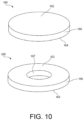
- the carbon/carbon disk brakes may be in the form of circular disks or annular disks.
- the carbon structure may comprise at least one of carbon, silicon carbide, silicon nitride, boron carbide, aluminum nitride, titanium nitride, boron nitride, zirconia, SiC x N y (wherein x is a number in the range from about zero to about 1, and y is a number in the range from about zero to about 4/3), silica, alumina, titania (TiO 2 ), and a combination of at least two of the foregoing.
- the carbon structure Prior to densification, the carbon structure may be referred to as a preform.
- a preform for use in making a carbon/carbon composite, such as a carbon/carbon disk brake may be referred to as a carbonized preform.
- carbon structure may be interchangeable with “carbon structure system.”
- a carbon structure system may comprise one or carbon structures that are associated.
- a carbon structure system may comprise two carbon structures coupled so that there is contact between each carbon structure, such as in a "stack.”
- a carbon structure system may comprise three or four carbon structures positioned so that at least two of the component carbon structures are in contact with each other.
- a carbon structure system may comprise four carbon structures positioned in a stack formation.
- a carbon structure may comprise any carbon structure derived from a fibrous material such as carbon fibers, silicon carbide fibers, and the like.
- the carbon fibers may be derived from polyacrylonitrile, rayon (synthetic fiber derived from cellulose), pitch, and the like.
- the fibrous material may be in the form of a woven, braided or knitted fabric or a needled felt.
- the fibrous material may be in the form of chopped carbon fibers molded to form a preform. Prior to the densification process, the fibrous material may be formed into a preform having any desired shape or form.
- the carbon structure may be in the form of a disk having any shape such as, for example, a polygon, a cylinder, a triangle, square, rectangle, pentagon, hexagon, octagon, and the like.
- the carbon structure may have an irregular form.
- the carbon structure may comprise a first surface, a second surface and at least one other surface connecting the first surface and the second surface.
- any surface may be any shape such as, for example, at least one of rounded, sphere shaped, toroid shaped, or frustoconical.
- the carbon structure may be in the form of a disk having a first generally planar surface and a second generally planar surface.
- the second generally planar surface may be positioned opposite the first generally planar surface.
- the term "generally planar surface” is used herein to denote the fact that the planar surfaces are not absolutely flat surfaces inasmuch as the carbon structure is porous and the planar surfaces have relatively rough surfaces as a result of the porous construction.
- at least one surface of the carbon structure is generally non-planar.
- the carbon structure may have a first generally planar surface and a second non-planar surface or a first non-planar surface and a second non-planar surface.
- the first and second generally planar surfaces may be bounded by the at least one other surface which may comprise at least one peripheral surface.
- the peripheral surface may comprise a circumferential surface.
- the carbon structure may be in the form of a circular disk or an annular disk. When in the form of a circular disk, the first and second generally planar surfaces may be bounded by an outside peripheral surface. When in the form of an annular disk, the first and second generally planar surfaces may be bounded by an outside peripheral surface and an inside peripheral surface.
- the carbon structure may be heat treated prior to densification.
- the heat treating may be conducted in a vacuum (e.g., by system 110 in Fig. 3 ) or an inert atmosphere at a temperature in the range from about 1400 to about 2800°C, and in one embodiment in the range from about 1600 to about 2200°C, for a period of time in the range up to about 60 hours, and in one embodiment in the range up to about 10 hours.
- this heat treating step may be referred to as a carbonizing step, and the heat treated carbon structure may be referred to as a carbonized preform.
- the carbonized preforms may be in the form of circular or annular disks. These preforms may be used to make carbon/carbon brake disks.
- the pore size and pore volume of the carbon structure should be sufficient to permit a gas to infiltrate the pores under reaction conditions and form a solid residue or matrix therein as a result of thermal decomposition.
- the gas or feed gas may comprise any gas that upon thermal pyrolysis forms a desired solid residue in the pores of the carbon structure. Stated another way, the gas or feed gas may comprise a precursor to a substance that forms desired solid residue in the pores of the carbon structure.
- the gas may comprise one or more hydrocarbons.
- the hydrocarbons may comprise alkanes, for example, straight chain, branched chain and/or cyclic alkanes, having from 1 to about 8 carbon atoms, and in one embodiment from 1 to about 6 carbon atoms, and in one embodiment from 1 to about 3 carbon atoms. Methane, ethane, propane, cyclopentane, or mixtures of two or more thereof may be used.
- the gas may comprise one or more alkenes of 2 to about 8 carbon atoms, and in one embodiment from 2 to about 6 carbon atoms. Mixtures of one or more alkanes of 1 to about 8 carbon atoms with one or more alkenes of 2 to about 8 carbon atoms may be used.
- the gas may comprise one or more precursors of silicon carbide.
- An example of such a precursor may comprise methyltrichlorosilane, hydrogen and nitrogen.
- Another precursor may comprise dimethyldichlorosilane, silicon tetrahydride and a carbon source such as methane.
- the gas may comprise one or more precursors of boron carbide (B 4 C) or Si 3 N 4 .
- An example of a precursor of boron carbide may comprise a mixture of hydrogen, methane and boron trichloride.
- the gas may further comprise one or more diluent and/or inert gases, for example, hydrogen, nitrogen, helium, argon, or a mixture of two or more thereof.
- the volume to volume ratio of diluent and/or inert gas to reactant gas may be in the range from about 0:1 to about 50:1, and in one embodiment in the range from about 0.1: 1 to about 50:1, and in one embodiment in the range from about 0.1: 1 to about 30:1, and in one embodiment in the range from about 0.1: 1 to about 15:1, and in one embodiment in the range from about 0.1: 1 to about 10:1, and in one embodiment in the range from about 0.2:1 to about 10:1, and in one embodiment in the range from about 0.5:1 to about 5:1.
- Pressure gradients may also be used with thermal gradients in various embodiments.
- a pressure gradient may be created when pressure on one surface of a carbon structure is different that the pressure at another surface of the carbon structure.
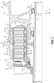
- a disk brake system 20 is illustrated.
- the disk brake system 20 may be used to reduce the speed of a wheel of an aircraft.
- An A-R-C axis has been included in the drawings to illustrate the axial (A), radial (R) and circumferential (C) directions.
- the system may include a wheel 10 supported for rotation around an axle 12 by bearings 14.
- the wheel 10 includes rims 16 for supporting a tire, and a series of axially extending rotor splines 18 (one shown). Rotation of the wheel 10 is modulated by the disk brake system 20.
- the disk brake system 20 includes a torque flange 22, a torque tube 24, a plurality of pistons 26 (one shown), a pressure plate 30, and an end plate 32.
- the pressure plate 30 and the end plate 32 are annular disks.
- the torque tube 24 is an elongated annular structure that includes a reaction plate 34 and a series of axially extending stator splines 36 (one shown).
- the reaction plate 34 and stator splines 36 may be integral with the torque tube 24 as shown in Fig. 1 or attached as separate components.
- the disk brake system 20 also includes a plurality of friction disks 38.
- the plurality of friction disks 38 includes at least one non-rotatable friction disk, also known as a stator friction disk 40, and at least one rotatable friction disk, also known as a rotor friction disk 42.
- Each of the plurality of friction disks 38 includes an attachment structure.
- each of four stator friction disks 40 include a plurality of stator lugs 44 at circumferentially spaced positions around the stator friction disk 40 as an attachment structure.
- each of five rotor friction disks 42 include a plurality of rotor lugs 46 at circumferentially spaced positions around the rotor friction disk 42 as an attachment structure.
- the pressure plate 30, end plate 32, and friction disks 38 are all annular disks.
- the torque flange 22 is mounted to the axle 12.
- the torque tube 24 is bolted to the torque flange 22 such that the reaction plate 34 is near an axial center of the wheel 10.
- the end plate 32 is connected to a surface of the reaction plate 34 facing axially away from the axial center of the wheel 10.
- the stator splines 36 support the pressure plate 30 so that the pressure plate 30 is also non-rotatable.
- the stator splines 36 also support the stator friction disks 40.
- the stator friction disks 40 engage the stator splines 36 with gaps formed between the stator lugs 44.
- the rotor friction disks 42 engage the rotor splines 18 with gaps formed between the rotor lugs 46.
- the rotor friction disks 42 are rotatable by virtue of their engagement with the rotor splines 18 of the wheel 10.
- the rotor friction disks 42 are arranged with the end plate 32 on one end (having an end plate thickness 33), the pressure plate 30 on the other end (having a pressure plate thickness 31), and the stator friction disks 40 (each having a stator thickness 41) interleaved so that the rotor friction disks 42 (each having a rotor thickness 43) are adjacent to non-rotatable friction components.
- the number of rotor friction disks 42 and stator friction disks 40 may vary according to the brake assembly design.
- the pistons 26 are connected to the torque flange 22 at circumferentially spaced positions around the torque flange 22.
- the pistons 26 face axially toward the wheel 10 and include pucks 54 that contact a side of the pressure plate 30 opposite the rotor friction disks 42.
- the pistons 26 may be powered electrically, hydraulically or pneumatically.
- pistons 26 prior to operation of the disk brake system 20, pistons 26 are not actuated and gaps exist between each of rotor friction disks 42 and each of the non-rotatable friction components, namely pressure plate 30, end plate 32, and stator friction disks 40.
- the gaps are formed by the axial spreading out of the rotor friction disks 42 along the rotor splines 18; and the stator friction disks 40, and the pressure plate 30 along the stator splines 36 due to the movement of the rotor friction disks 42 adjacent to the non-rotatable friction components.
- pistons 26 are actuated, forcing the pressure plate 30 to move along stator splines 36 against the plurality of the friction disks 38, forcing them axially toward the end plate 32 and reaction plate 34. Squeezed between the pressure plate 30 and the reaction plate 34, the gaps are eliminated as friction surfaces contact other friction surfaces.
- the friction disks 38 of the disk brake system 20 may be comprised of carbon structures comprising carbon composite material. Contact between friction disks 38 during operation of the disk brake system 20 as described above causes the friction disks 38 to wear over time.
- ceramic particles may be incorporated into the carbon materials during the fabrication process of the carbon composite material comprised in the friction disks 38.
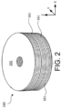
- Fibrous preform 100 may comprise a porous structure comprised of a plurality of stacked textile layers 102.
- a porous structure includes any structure derived from a fibrous material such as carbon fibers or the like.
- the carbon fibers may be derived from polyacrylonitrile (PAN), rayon (synthetic fiber derived from cellulose), oxidized polyacrylonitrile fiber (OPF), pitch, or the like.
- the starting fiber may be pre-oxidized PAN or fully carbonized commercial carbon fiber.
- Fibrous preform 100 may be prepared by needling the textile layers 102 of fibrous preform 100. Needling the textile layers 102 tends to push fibers from one layer 102 into the next layer 102, thereby forming z-fibers that extend perpendicularly across the layers 102. After needling, fibrous preform 100 may comprise fibers extending in three different directions (i.e., in the x and y directions and the z direction).
- the hard ceramic particles may be desirable to incorporate the hard ceramic particles into the carbon structure to improve the wear rate of the carbon composite material comprised in friction disks 38 from Fig. 1 .
- articles comprising zirconium compounds such as zirconium oxycarbides and zirconium carbides, for example, may be incorporated into wear products such as friction disks 38 via infiltration of ceramic particles in fibrous preform 100, to improve wear rate.
- zirconium compounds are suitable for this purpose in part because of the abundance and affordability of zirconium raw materials.
- yttrium compounds may be introduced to the carbon structure during the fabrication process.
- Yttrium compounds are hard, dense compounds (in various physical forms), and therefore, the addition of particles comprising yttrium compounds may provide better wear properties for the friction disks 38 than zirconium particles alone.
- Yttrium raw materials are typically rarer and, thus, more expensive than zirconium raw materials, especially in fine particle size powders or suspensions of zirconium raw materials.
- Yttria-stabilized zirconia powders and/or suspensions have become commercially available at an affordable cost.
- dense zirconia products may be manufactured with a doping agent, such as yttrium oxide, to stabilize the zirconia.
- the hardness and wear rate of the carbon composite material in the friction disks 38 may be increased and improved by incorporating yttria-stabilized zirconia into the carbon structure during the fabrication process of the friction disks 38. After densification, the carbon structure comprising the carbon composite material 50 of the friction disks 38 may be left with a plurality of ceramic particles to increase hardness and improve wear rate.
- the carbon composite material 50 of the friction disks 38 may comprise ceramic particles of one or more of zirconium oxycarbide, zirconium carbide, yttrium oxycarbide and/or yttrium carbide.
- the carbon composite material 50 of the friction disks 38 may comprise residual yttria-stabilized zirconia.
- the various combinations of zirconium particles and yttrium particles tend to improve the wear rate. While not desiring to be bound by theory, it is thought that this effect is because of the added hardness and density from yttrium oxycarbide and yttrium carbide particles.
- the plurality of ceramic particles including zirconium oxycarbide, zirconium carbide, yttrium oxycarbide, and/or yttrium carbide, and possibly residual yttria-stabilized zirconia, in the carbon composite material 50 may comprise 0.5% to 12% of the finished carbon-carbon structure, by weight.
- each ceramic particle in the carbon composite material 50 of the friction disks 38 may comprise a size of less than 500 nanometers.
- the processes disclosed herein may include treatments for producing carbon fiber reinforced carbon composite material.
- carbon structure may be used to describe a carbon preform 100, a carbon fiber reinforced carbon material at various stages of densification, a carbon structure prior to densification and carbon reinforcement, and/or a finished carbon composite material.
- the processes for treating carbon structures disclosed herein further include infiltration of a ceramic preparation, comprising ceramic particles having zirconium oxides and yttrium oxides, into a carbon structure to prepare the carbon structure.
- the ceramic particles may have zirconium oxides and yttrium oxides that are in a combined state at the particle level and/or molecular level, for example, in particles comprising yttria-stabilized zirconia.
- the ceramic particles may have zirconium oxides and yttrium oxides that are not in a combined state at the particle level and/or molecular level, and instead the zirconium oxides and yttrium oxides may be in a separated state.
- ceramic preparation describes a ceramic suspension, which may be a colloidal suspension, and/or a ceramic sol gel for infiltration into a carbon structure.
- ceramic compounds that are zirconium compounds and/or yttrium compounds
- the present disclosure is not limited in this regard.
- ceramic compounds (or additives) as disclosed herein can include titanium, boron, boron carbide, graphene, or any combination of the aforementioned compounds.
- the carbon structure 160 may be infiltrated with a SiOC precursor preparation.
- the SiOC precursor preparation may be a sol formed by mixing water and an alkyltrimethoxysilane (e.g., methyltrimethoxysilane ("MTMS")).
- MTMS methyltrimethoxysilane
- FIG. 3 an exemplary preform infiltration system 110 is shown, in accordance with various embodiments.
- System 110 may include a fluid reservoir 112 for storing and delivering the SiOC precursor suspension into the vacuum chamber 114.
- Vacuum chamber 114 is equipped with a tank in which the carbon structure 160 ( Fig. 2 ) may be located.
- Vacuum pump 118 and trap 116 are used to first evacuate the porosity of the carbon structure 100 and subsequently facilitate drawing the SiOC precursor suspension into the tank containing the parts to be infiltrated (e.g., the carbon structure 160).
- the carbon structure 160 are removed and dried in a separate oven.
- the SiOC precursor preparation may be applied by dipping the carbon structure 160 in the sol or by any other suitable application method
- the infiltrated carbon structure 160 may undergo a series of heat treatment(s) and densification cycles.
- the incorporation of SiOC precursors throughout the fibrous preform 100 or throughout a partially densified fibrous preform may lead to the formation of SiOC particles during the subsequent heat treatments and a series of carbon densification cycles.
- Additives such as a wetting agent may be included in the SiOC precursor suspension to facilitate wetting of the preform or of the partially densified carbon structure 160.
- subsequent heat treatments of the carbon structure 160 which, in various embodiments, may be performed in the presence of nitrogen gas, the SiOC precursors are transformed into SiOC particles.
- the SiOC particles may comprise an average particle size of less than 500 nm, less than 250 nm, less than 100 nm and or less than 50 nm (e.g., an average particle size of between 10 nm and 500, between 10 nm and 250 nm, between 10 nm and 100, or between 10 and 50 nm). In various embodiments, the SiOC particles may comprise an average particle size of between 0.5 micrometers and 5 micrometers.
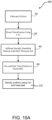
- a fiber preform may be fabricated (Step 202).
- the fiber preform or carbon structure may comprise a carbon structure.
- a carbon structure may comprise any carbon structure derived from a fibrous material such as carbon fibers or the like.
- the carbon fibers may be derived from polyacrylonitrile (PAN), rayon (synthetic fiber derived from cellulose), pitch, or the like.
- the starting fiber may be pre-oxidized PAN or fully carbonized commercial carbon fiber.
- the fibrous preform is preferably prepared using needling of individual textile layers.
- the individual brake preform may be fabricated using a net shape preforming technology or may be cut from a needled board.
- preforms may be a 2D lay-up of woven, braided or knitted fabric.
- the fibrous material may be in the form of chopped carbon fibers molded to form a preform. Prior to the densification process, the fibrous material may be formed into a preform having any desired shape or form.
- the carbon structure may be in the form of a disk having any shape such as, for example, a polygon, a cylinder, a triangle, annular, square, rectangle, pentagon, hexagon, octagon, or the like.
- the carbon structure may have an irregular form.
- the preform may be heat treated (Step 204) at temperatures between 1000°C and 2200°C. Heat treatments described herein may vary in temperatures and durations.
- the preform may be infiltrated with a ceramic preparation that is at least one of a ceramic colloidal suspension or sol gel solution prepared with a selected ceramic content (Step 206).
- the ceramic content can include an aqueous colloidal suspension of very fine oxides and boron or oxide boron compounds.
- the starting colloidal oxides may be nano-size suspensions.
- the boron compound powders may be as small as possible, less than 2 micron and preferably submicron size.
- the ceramic content can include yttrium compounds and zirconium compounds.
- the yttrium compounds and zirconium compounds may be combined at the particle level, for example, in particles comprising yttria-stabilized zirconia.
- an aqueous colloidal suspension comprising yttria-stabilized zirconium compounds, such as Y 2 O 3 -ZrO 2 may be introduced in the carbon composite as described in detail below.
- the starting ceramic powders may comprise ceramic particles of yttria-stabilized zirconia having various sizes, for example, sizes ranging from 40 nanometers to 60 nanometers (1.57e -6 inches to 2.36e -6 inches), or from 10 nanometers to 13 nanometers (3.9e -7 inches to 5.1e -7 inches).
- the incorporation of a controlled starting amount of very fine ceramic particles, comprising particle sizes described herein, throughout the carbon composite may lead to the formation of ultra-fine boride particles (e.g., zirconium diboride, titanium diboride, and/or yttrium diboride), very fine yttrium, zirconium compounds, or the like following subsequent heat treatments and further carbon densification cycles, comprising sizes below 500 nanometers (2.0e -5 inches).
- the borides may be a single boride, a mixed borides or a combined boride.
- This may be accomplished by the preparation and introduction of a suspension containing either a single oxide like ZrO2 or TiO2 and a boron source; or mixed oxides like ZrO2 and TiO2 and a boron source; or a combined oxide like ZrO2/Y2O3 and a boron source.
- Additives such as a wetting agent are made to the ceramic suspension to facilitate wetting of the preform or of the partially densified carbon structure.
- a boride or mixed borides may be formed through borothermal reduction of the oxide or oxides, or more specifically, a carbo-thermal reduction of yttrium oxides and zirconium oxides may occur, yielding zirconium oxycarbide, zirconium carbide, yttrium oxycarbide, and/or yttrium carbide compounds.
- residual yttrium oxides and zirconium oxides which may be combined as yttria-stabilized zirconia, may remain after the heat treatments.
- the oxide compounds may be introduced using sol gel solution starting with one or several alkoxides such as zirconyl nitrate, zirconium butoxide, zirconium propoxide, titanium isopropoxide, titanium butoxide, tetrabuthyl titanate, yttrium nitrate.
- the boron source may be one of several compounds including boric acid.
- This may be accomplished by adding a carbon compound to the starting suspension in the form of one or several water soluble polymers such as a polyvinyl alcohol (PVA), polyvinylpyrrolidone (PVP), polyvinyl acetate, poly (2-oxazoline), polyacrylamide (PAM), polyethyleneimine (PEI), and/or polyacrylate (PAA).
- PVA polyvinyl alcohol
- PVP polyvinylpyrrolidone
- PAM polyacrylamide
- PEI polyethyleneimine
- PAA polyacrylate
- aqueous emulsion of polyester, epoxy, or phenolic may be also used.
- Aqueous carbon black dispersions may be used as the additional carbon source, or to supplement a water-soluble polymer. These carbon sources exhibit various char yields and may be introduced in the form of one or more components.
- the pH of the ceramic suspension Prior to adding the additional carbon compound to the ceramic suspension, the pH of the ceramic suspension may be adjusted. For example, the pH of the ceramic suspension may be made more basic by adding ammonium hydroxide or other similar Arrhenius base.
- effectiveness of the carbon addition may be improved by pursuing the individual carbon coatings of the ceramic particles comprising yttrium oxides and/or zirconium oxides, which may be in a combined state in, for example, yttria-stabilized zirconium.
- Encapsulation of the ceramic particles with a thin polymeric layer of carbon during the preparation of the suspension may be accomplished by the addition of a polyelectrolyte dispersant or organic acid, such as citric acid, trans-aconitic acid, or cis-aconitic acid, into the ceramic suspension, which absorbs and coats the ceramic particles.
- the type and amount of polyelectrolyte may be chosen to provide a sufficient carbon char yield upon heat treatment in an inert atmosphere.
- dispersants include ammonium polyacrylates, polyethyleneimine, and/or polyacrylamide.
- the absorbed layer of polymer may be pyrolyzed into a carbon film.
- the addition of an aqueous carbon black dispersion and/or additional water soluble polymer to the colloidal ceramic suspension may take place to achieve a greater amount of carbon.
- the addition of an aqueous carbon black dispersion and/or additional water soluble polymer to the colloidal ceramic suspension may take place following the formation of an adsorbed polymer layer on the ceramic particles from the polyelectrolyte dispersant or organic acid, or the carbon black dispersion and/or the water soluble polymer may be the only source of carbon in the ceramic preparation.
- the polymer may take different forms.
- the polymer may be a non-ionic polymer like PVA, PAM, an aqueous emulsion of polyester, epoxy, or phenolic, or a combination of two or more of the polymers.
- the molecular weight and quantity of polymer may be chosen to maintain the overall viscosity of the colloidal suspension low in order to facilitate its infiltration within the carbon composite.
- the aqueous ceramic suspension may be prepared from dry ceramic powder, comprising yttria-stabilized zirconia, and/or already suspended yttria-stabilized zirconia particles.
- the zirconia particles may be partially or fully stabilized by yttria, depending on the amount of yttria incorporated into the zirconia compounds.
- Zirconia particles partially stabilized by yttria may comprise uniform dispersion of 3 mol% of yttria, or about 5.2% by weight, wherein the term "about” in this context only refers to plus or minus 0.2%.
- Zirconia that is fully stabilized by yttria may comprise 4, 6, 8, and/or 10 mol% content, or about 7, 10.3, 13.3, and 15.9% by weight, respectively, wherein the term "about” in this context only refers to plus or minus 0.2%.
- a dry ceramic powder comprising agglomerated ceramic granules of yttria-stabilized zirconia, and/or an yttria-stabilized zirconia suspension, may be added to distilled water.
- the ceramic suspension may be dispersed using a high energy mixer, such as an attrition mill of a high shear mixer, in order to break down the ceramic granules to their elementary nanosize original states.
- the ceramic suspension may be further de-agglomerated using ultrasounds.
- a wetting agent may be added to facilitate wetting of the preform and or partially densified carbon structure.
- the pH of the ceramic suspension may be raised to a level at or between 10 and 11 using ammonium hydroxide, which may comprise 0.3% of ammonium polyacrylate polyelectrolyte.
- oxide sources may include nano suspensions of zirconia, yttria stabilized zirconia, TiO 2 , and/or Y 2 O 3 .
- oxide sources may further include sol gel from one or several alkoxides such as zirconyl nitrate, zirconium butoxide, titanium isopropoxide, titanium butoxide, yttrium nitrate.
- a Ti or Zr source may be a chelate such as aqueous titanium lactate, aqueous zirconyl chloride compound.
- Ceramic colloidal suspensions comprising yttrium oxides and zirconium oxides may be prepared using various materials.
- a dry ceramic powder comprising 10% by weight of yttria-stabilized zirconia (Y 2 O 3 -ZrO 2 , with 16% Y 2 O 3 by weight) may be added to distilled water comprising 0.2% ammonium polyacrylate polyelectrolyte.
- the ceramic powder may be made of nanosize particles, which may be available in agglomerated granules to limit the health hazard associated with the handling of nanosize powder.
- the ceramic granules comprised in the ceramic powder may be dispersed using a high energy mixer, such as an attrition mill of a high shear mixer, in order to de-agglomerate the ceramic granules to their elementary nanosize original states.
- the pH of the solution may be increased to at or between 10 and 11 by adding ammonium hydroxide.
- Non-ionic aqueous nano carbon black having a pH at or between 9 and 11, may be added and mixed into the ceramic suspension.
- the amount of added carbon black may correspond to a ratio of carbon/yttria-stabilized zirconia of 0.29, or 2.8% of the total ceramic suspension.
- the ceramic suspension may further be de-agglomerated using ultrasounds.
- a dry ceramic powder comprising 21% by weight of yttria-stabilized zirconia (Y 2 O 3 -ZrO 2 , with 5.2% Y 2 O 3 by weight) may be added to distilled water comprising 2% citric acid polyelectrolyte.
- the pH of the solution may be increased to at or between 10 and 11 by adding ammonium hydroxide.
- the ceramic granules comprised in the ceramic powder may be dispersed using a high energy mixer, such as an attrition mill of a high shear mixer, in order to de-agglomerate the ceramic granules to their elementary nanosize original state.
- Non-ionic aqueous nano carbon black comprising a particle size of 30 nanometers (1.2e-6 inches) and having a pH at or between 9 and 11, may be added and mixed into the ceramic suspension.
- the amount of added carbon black may correspond to a ratio of carbon/yttria-stabilized zirconia of 0.22.
- the ceramic suspension may further be de-agglomerated using ultrasounds.
- possible boron sources may include boron, boron carbide powder, boron oxide powder, and/or boric acid.
- the aqueous ceramic suspension may be infiltrated either within the porosity of the preform or within the porosity of partially densified carbon-carbon. The infiltration may be conducted by immersing the preform or partially densified carbon-carbon in the aqueous ceramic suspension. Infiltration may also be conducted following evacuation of the pores using a vacuum chamber 114 from Fig. 3 . Following introduction of the slurry within the part, the part may be dried to remove water. The targeted amount of dry ceramic compound ranges from 0.5% to 12% by weight of the finished carbon composite. The ceramic content of the aqueous ceramic suspension may be selected to leave ceramic compounds in the targeted range. The range may provide wear improvement benefit without negatively impacting the mechanical properties of the carbon composite.
- a ceramic colloidal suspension comprising 25% by weight of yttria-stabilized zirconia (Y 2 O 3 -ZrO 2 , with 16% Y 2 O 3 by weight) may be added to distilled water to produce a 15% by weight yttria-stabilized zirconia loading suspension.
- the pH of the solution may be increased from 5 to 11 by adding ammonium hydroxide with 0.3% ammonium polyacrylate polyelectrolyte.
- the ceramic suspension may be dispersed using a high energy mixer, such as an attrition mill of a high shear mixer.
- Non-ionic aqueous nano carbon black which may comprise 35.5% by weight of carbon black and may have a pH at or between 9 and 11, may be added and mixed into the ceramic suspension.
- the amount of added carbon black may correspond to a ratio of carbon/yttria-stabilized zirconia of 0.18.
- the ceramic suspension may further be de-agglomerated using ultrasounds.
- a ceramic colloidal suspension comprising 25% by weight of yttria-stabilized zirconia (Y 2 O 3 -ZrO 2 , with 13.6% Y 2 O 3 by weight) may be added to distilled water, polyelectrolyte, PVA, and carbon black to produce a 6% by weight yttria-stabilized zirconia loading suspension.
- the ceramic suspension may comprise 1.1% PVA and 1% carbon black (dry weight).
- the pH of the solution may be increased from 5 to 11 by adding ammonium hydroxide and 0.3% ammonium polyacrylate polyelectrolyte.
- the ceramic suspension may be dispersed using a high energy mixer, such as an attrition mill of a high shear mixer.
- the carbon black added to the ceramic suspension may be non-ionic aqueous nano carbon black, which may comprise 35.5% by weight of carbon black and may have a pH at or between 9 and 11.
- the amount of added carbon black may correspond to a ratio of carbon/yttria-stabilized zirconia of 0.17 following the transformation of PVA into carbon.
- the ceramic suspension may further be de-agglomerated using ultrasounds.
- the ceramic preparation which may be an aqueous ceramic suspension, or slurry, may infiltrate the porosity of a carbon preform, the porosity of partially densified carbon structure, and/or other carbon structure.
- the porosity of a carbon structure refers to the pores, or spaces, between the carbon fibrous network.
- the infiltration may be conducted by immersing the carbon preform or partially densified carbon structure in the aqueous ceramic suspension. In various embodiments, infiltration may be conducted following evacuation of the pores of the carbon structure using a vacuum chamber 114 from Fig. 3 .
- the carbon structure may be dried to remove water.
- the ceramic content of the aqueous ceramic suspension or ceramic preparation may be selected to leave ceramic compounds of a targeted amount in the finished carbon composite.
- the targeted amount of dry ceramic compound comprising yttrium oxycarbides, yttrium carbides, zirconium oxycarbides, zirconium carbides, residual yttria-stabilized zirconia, and/or any other dry ceramic compound disclosed previously herein may range from 0.01% to 12% by weight of the finished carbon composite, or between 0.01% to 6% by weight, or between 0.1% and 0.5% by weight, or between 0.1% and 0.4% by weight.
- That range may provide wear improvement of the carbon structure when used in applications such as brake disks, while significantly reducing vibrational effects from the ceramic compound compared to typical carbon structures with ceramic content therein.
- the ceramic compounds may cause increased friction / torque sensitivity at low energies, creating a negative mu-V slope frictional response and/or excessive vibration.
- the ceramic particles, comprising yttrium oxides and/or zirconium oxides, in the ceramic preparation may infiltrate the carbon structure at one stage of the carbon composite fabrication, for example at the preform level, as shown in Step 206.
- the ceramic particles in the ceramic preparation may infiltrate carbon structure prior to densification only (i.e., prior to step 210) in order to ensure the CVI process produces a uniform density gradient across the carbon structure to accommodate for the decrease in wear life from providing a lower amount of ceramic content.
- the preform may be heat treated to a suitable temperature in an inert environment so as to transform the added polymer or other carbon source, such as carbon black, into amorphous carbon.
- This step may be conducted in a separate furnace or during the ramp up to the temperature of a CVI pyrolytic carbon densification cycle.
- the carbon structure may be heat treated in inert atmosphere to fully or partially complete the thermo-reduction of the yttrium oxides to yttrium oxycarbides and/or yttrium carbides, and the zirconium oxides to zirconium oxycarbides and/or zirconium carbides by the additional source of carbon in the form of pyrolyzed polymers and/or carbon black.
- heat treatment may be conducted only after specific CVI densification cycles, for example, following the final CVI densification step 210.
- the preform may be dried (Step 208).
- the preform may further be densified using one or multiple CVI cycles (Step 210). Each CVI cycle may be followed by a heat treatment, as depicted in Step 210.
- the carbon structure may be subjected to a heat treatment between 1000°C and 1600°C, for example.
- the apparatus for conducting the densification process may comprise densification chamber 100 which contains densification unit 120.
- the densification chamber 100 may be in the form of a cylindrical pressure vessel.
- Densification unit 120 may be circular to conform to the shape of the densification chamber 100.
- Support structure 140 forms part of the densification unit 120, and carbon structure 160 is mounted on support structure 140.
- Seal ring 180 is positioned between the support structure 140 and the carbon structure 160. Seal ring 180 may be formed separately from the support structure 140 and then mounted on the support structure 140, or it may be formed integrally with the support structure 140.
- the carbon structure 160 has a first surface 162, which may be in the form of a first generally planar surface, and a second surface 164, which may be in the form of a second generally planar surface.
- the first and second surfaces are connected by at least one other surface.
- the carbon structure 160 may be in the form of a circular disk or an annular disk.
- the circular disks have outside diameters (OD), while the annular disks have both outside diameters (OD) and inside diameters (ID).
- the at least one other surface may be in the form of peripheral surface 166 (circular disk) or peripheral surfaces 166 and 167 (annular disk).
- the carbon structure 160 may be in the form of an annular disk as illustrated in Figs. 6 , 8 , 10 , 11, and 12 .
- the carbon structure 160 when in the form of an annular disk, has a center opening 165, and the at least one other surface comprises outside peripheral surface 166 and inside peripheral surface 167.
- the support structure 140 may comprise any support fixture assembly that does not interfere with the flow of gas through the first and second surfaces 162 and 164, and the at least one other surface (e.g., peripheral surfaces 166 and 167) of the carbon structure 160.
- the support structure 140 may not contact the surfaces 162 and 164 or the peripheral surfaces 166 and 167.
- the first surface 148 of the support structure 140 may comprise a perforated or porous material that is sufficiently porous to permit gas flow to and through the second surface 164 of the carbon structure 160 and, in this embodiment, the first surface 148 of the support structure 140 may contact the second surface 164 of the carbon structure 160.
- the seal ring 180 which may be formed separately from or integrally with the support structure 140, may contact part of the second surface 164 of the carbon structure 160.
- the densification unit 120 includes cooling element 142 which is in thermal contact with second generally planar surface 164 of the carbon structure 160 and is adapted for cooling the second surface 164.
- the cooling element 142 may comprise one or more cooling conduits or channels in the support structure 140.
- the cooling element 142 may use any suitable fluid coolant such as water, nitrogen, oil, and the like. The coolant may flow into and out of the cooling element 142 as indicated by arrows 144 and 146.
- the cooling element 142 may comprise one or more non-fluid cooling elements.
- the densification unit 120 includes heating element 122 (a heating element may also be referred to as a "heating source” or “heat source”), as shown in FIG. 5 .
- Heating element 122 is positioned in thermal contact with the first surface 162 of the carbon structure 160 and is adapted for heating the first surface 162.
- the heating element 122 may be in the form of a susceptor, resistance heating element or microwave heating element.
- an induction coil and an insulation barrier may be used in combination with the heating element 122.
- the heating element 122 may be positioned above and aligned perpendicular to the carbon structure 160, as illustrated in Fig. 1 .
- the heating element may be in the form of a vertically oriented cylindrical structure with a center opening to permit the flow of gas through the center opening away from the carbon structure 160.
- the heating element 122 may be positioned above or apart from and aligned parallel with the first surface 162.
- the heating element 122 may be positioned at an inclined angle relative to the first surface 162.
- the heating element 122 may be spaced sufficiently from the carbon structure 160 to permit gas flowing through the carbon structure to flow away from the carbon structure.
- a protective shroud may be positioned between the heating element 122 and the carbon structure 160 to protect the heating element from reactive gases forming solid deposits on the heating element.
- the protective shroud may be made of any suitable material, for example, graphite.
- the densification unit 120 includes lower wall 124, and cylindrical wall section 126. Cylindrical wall section 126 surrounds support structure 140 and carbon structure 160.
- the densification unit 120 includes upper wall 127 and exhaust outlet 128. The upper wall 127 may form part of the heating element 122.
- the densification unit 120 includes insulation layer 130 which is positioned between the cylindrical wall section 126, and the support structure 140 and carbon structure 160. The use of insulation layer 130 is optional.
- the densification unit 120 includes gas inlet 132.
- the densification chamber 100 includes exhaust outlet 102 which may be connected to a vacuum system (system 110 from fig. 3 ).
- the vacuum system may comprise any vacuum system capable of reducing the pressure within the densification chamber 100 to a level of about 1 torr or less, and in one embodiment to a level of about 0.1 torr or less.
- the vacuum system may also be adapted for withdrawing exhaust gases from the densification chamber 100 through outlet 102 during the densification process.
- the support structure 140 has a first surface 148 which may be positioned opposite the second surface 164 of the carbon structure 160.
- the first surface 148 may also function as part of the cooling element 142.
- a first open space 150 may be positioned between the first surface 148 of the support structure 140 and the second surface 164 of the carbon structure 160.
- the first open space 150 may be positioned within the side walls of seal ring 180.
- the first open space 150 may be adapted for receiving gas flowing from the gas inlet 132 into contact with the second surface 164 of the carbon structure 160.
- a second open space 152 may be positioned adjacent to the peripheral surface 166 of the carbon structure 160.
- the second open space 152 may be adapted for permitting gas to flow out of the carbon structure 160 through the peripheral surface 166.
- a third open space 154 may be positioned adjacent the first surface 162 of the carbon structure 160.
- the third open space 154 may be adapted for permitting gas to flow out of the carbon structure 160 through the first surface 162.
- the heating element 122 is positioned parallel to the first surface 162
- the third open space 154 may be positioned between the heating element 122 and the first surface 162.
- a fourth open space or center opening 165 may be positioned adjacent to the inside peripheral surface 167 of the carbon structure 160.
- the fourth space 165 may be adapted for permitting gas to flow out of the carbon structure 160 through the inside peripheral surface 167.
- the seal ring 180 illustrated in Fig. 7 may have a layer of graphite cement 182 positioned between it and the second generally planar surface 164 of the carbon structure 160.
- the seal ring 180 may also have a gasket 184 positioned between it and the first surface 148. Use of the layer of graphite cement 182 and gasket 184 is optional. Clamps 185 and 186 may be provided for holding the carbon structure 160, seal ring 180 and support structure 140 together.
- the seal ring 180 may comprise a graphite seal ring.
- the gasket 184 may comprise a flexible graphite gasket.
- the gasket 184 may be made of GRAFOIL ® which is a flexible graphite available from GrafTech International Holdings Inc., 12900 Snow Road Parma, Ohio, USA, 44130. Although two clamps, namely clamps 185 and 186, are illustrated in Fig. 5 , any desired number of clamps may be used, for example, one, two, three, four, five, six, etc.
- the apparatus illustrated in Fig. 8 is the same as illustrated in Fig. 7 with the exception that carbon structure 160 is in the form of an annular disk rather than a circular disk.
- the carbon structure 160 illustrated in Fig. 6 includes center opening 165, which may be referred to as a fourth open space.
- the carbon structure 160 has an outside peripheral surface 166 and an inside peripheral surface 167.
- the apparatus may have an outside seal ring 180, which may be the same as the seal ring 180 illustrated in Fig. 5 , and an inside seal ring 187.
- the inside seal ring 187 may have a layer of cement 189 positioned between it and the second generally planar surface 164 of the carbon structure 160.
- the seal ring 187 may also have a gasket 188 positioned between it and the first surface 148.
- the layer of cement 189 and gasket 188 may be optional.
- the seal ring 187 may comprise a graphite seal ring.
- the layer of cement 189 may comprise a graphite cement.
- the gasket 188 may comprise a flexible graphite gasket.
- the gas inlet 132 and the first space 150 may each have an annular shape.
- the apparatus illustrated in Fig. 9 is the same as illustrated in Fig. 7 except that the carbon structure 160 has a reduced thickness, and seal ring 190 may overlie the outer portion 191 of the first generally planar surface 162 of carbon structure 160.
- the seal ring 190 may comprise a graphite seal ring. Clamps 185 and 186 may hold seal ring 190 against the first generally planar surface 162. The clamps may also hold the carbon structure 160, seal ring 180 and support structure 140 together.
- the carbon structure 160 may be mounted on the support structure 140.
- the heating element 122 may be heated to heat the first surface 162 to a temperature in the range from about 800 to about 1700°C, and in one embodiment in the range from about 850 to about 1500°C, and in one embodiment in the range from about 900 to about 1350°C.
- a coolant may flow in the cooling element 142 to provide cooling to the second surface 164 of the carbon structure 160.
- the temperature of the second surface 164 may be in the range from about 400 to about 1500°C, and in one embodiment in the range from about 500 to about 1200°C, and in one embodiment in the range from about 600 to about 1100°C.
- the difference in temperature between the temperature of the first surface 162 and the second surface 164 establishes a thermal gradient across the thickness of the carbon structure 160.
- the thickness of the carbon structure 160 may be the length extending from the first generally porous surface 162 to the second generally porous surface 164.
- the thermal gradient across the thickness of the carbon structure may be in the range from about 25 to about 450°C per centimeter of thickness (°C/cm) of the carbon structure 160, and in one embodiment in the range from about 50 to about 400°C/cm, and in one embodiment in the range from about 100 to about 350°C/cm, and in one embodiment in the range from about 150 to about 300°C/cm.
- the vacuum system (system 110 from Fig. 3 ) may be used to establish an absolute pressure in the open spaces 152, 154 and 165 in the range from about 1 to about 760 torr, and in one embodiment in the range from about 5 to about 100 torr, and in one embodiment in the range from about 5 to about 50 torr, and in one embodiment in the range from about 5 to about 20 torr, and in one embodiment about 10 torr.
- the feed gas may flow in gas inlet 132, as indicated by arrow 170, and from the inlet 132 into the space 150 in contact with the second surface 164 of the carbon structure 160.
- the absolute pressure in the open space 150 may be higher than in the open space 154 and may be in the range from about 5 to about 1000 torr, and in one embodiment in the range from about 5 to about 500 torr, and in one embodiment in the range from about 10 to about 200 torr.
- the difference in pressure between the pressure in the open space 150 and the pressure in the open space 154 may be in the range from about 5 to about 400 torr, and in one embodiment in the range from about 20 to about 200 torr.
- the difference in pressure between the pressure in the open space 150 and the pressure in the open spaces 152 and 165 may be in the range from about 5 to about 400 torr, and in one embodiment in the range from about 20 to about 200 torr.
- the pressure gradient across the thickness of the carbon structure 160 from the second surface 164 to the first surface 162 may be in the range from about 0.5 to about 1000 torr/cm, and in one embodiment in the range from about 1 to about 500 torr/cm, and in one embodiment in the range from about 2 to about 100 torr/cm, and in one embodiment in the range from about 5 to about 50 torr/cm.
- the pressure gradient across the carbon structure 160 from the second surface 164 to the peripheral surfaces 166 and 167 may be in the range from about 2 to about 1000 torr/cm, and in one embodiment in the range from about 5 to about 500 torr/cm.
- the feed gas may flow from the open space 150 into the carbon structure 160 wherein at least part of the gas undergoes thermal pyrolysis and forms a solid residue in the pores of the carbon structure 160.
- the gases that do not undergo thermal pyrolysis i.e., the unreacted gases
- any by-product gases that may be generated during the densification process may flow through the carbon structure 160 and out of the densification chamber 100 through the gas outlet 102, as indicated by arrow 172.
- the build up of solid residue within the carbon structure may result in a gradual densification of the carbon structure 160 and the formation of the composite structure 160.
- the densification generally proceeds from the hot side or the first surface 162 to the cold side or the second surface 164.
- the gases may flow through the carbon structure 160 to and through the first planar surface 162 and to and through the peripheral surfaces 166 and 167 as illustrated in Fig. 11 .
- the gases may flow through the carbon structure 160 to and through the peripheral surfaces 166 and 167 as illustrated in Fig. 12 .
- the early stage densification at least during the formation of a carbon/carbon/ceramic composite, may be conducted over a period of time in the range from about the first half to about the first three-quarters of the densification process.
- the late stage densification may be conducted over a period of time in the range from about the last half to about the last one-quarter of the densification process.
- the overall densification process may be conducted over a period of time in the range from about 10 to about 250 hours, and in one embodiment in the range from about 15 to about 175 hours, and in one embodiment in the range from about 24 to about 100 hours, and in one embodiment in the range from about 24 to about 75 hours, and in one embodiment in the range from about 24 to about 65 hours.
- the thermal gradient and/or pressure gradient across the carbon structure may be varied during the densification process in order to optimize the densification of the carbon structure. This may be accomplished by changing the temperature of the coolant in the cooling element 142 and/or changing the flow rate of the coolant in the cooling element. This may also be accomplished by changing the type of coolant used in the cooling element 142.
- the coolant is water
- the water may be chilled prior to entering the cooling element 142 to increase the temperature differential between carbon structure 160 and the cooling element 142. This may increase the heat transfer rate between carbon structure 160 and the cooling element 142.
- the heat transfer rate may be decreased during the densification process by allowing the water temperature in the cooling element 142 to rise.
- the pressure within the cooling element 142 may be increased to prevent the water from vaporizing. Coolants other than water, such as various oils with higher boiling points than water, may be used as the coolant. The coolants with higher boiling points than water may be used to operate the cooling element 142 at higher temperatures and thereby reduce the temperature differential between the cooling element 142 and the carbon structure 160.
- the flow rate within the cooling element 142 may be varied to vary the temperature within the cooling element. For example, a relatively high flow rate may tend to maintain the cooling element 142 at a relatively cool temperature, and a relatively low flow rate may allow the temperature of the cooling element 142 to increase.
- the pressure gradient across the carbon structure may be varied during the densification process by decreasing or increasing the feed gas flow rates. For example, the increase in the pressure gradient that occurs as a preform densifies may be limited to a maximum value by lowering the feed gas flow rates during the latter stages of the densification process.
- the thermal gradient may also be varied by moving the cooling element away from the carbon structure during the densification process and/or moving the carbon structure away from the cooling element during the densification process. This may be accomplished using the densification fixtures illustrated in Fig. 6 .
- the densification fixtures 125 include support pipe 141, threaded rod 143, nut 151, bottom plate 149, clamps 147 at the outside diameter of the carbon structure 160, top clamp 157 which may include holes for gas flow, seal ring 153, lower clamp/seal 158, and insulators 133.
- the bottom plate 149, nut 151, top clamp 157, and lower clamp/seal 158 may be made of graphite.
- the insulators 133 may be made of carbon foam.
- the densification fixtures 125 include gas inlet 132, and temperature indicator leads 156. Also included are first open space 150, second open space 152, third open space 154 and fourth open space 165 which are the same as described above.
- the densification process may be conducted by establishing a thermal gradient across the carbon structure 160 as discussed above using heating elements (not shown in Fig. 6 ) and a coolant (e.g., water or oil) in cooling element 145.
- the reactant gas may flow through the support pipe 141 into the first space 150 and from the first space 150 into the carbon structure 160 as described above and as shown in Fig. 6 by arrows 155.
- the gap between the carbon structure 160 and the cooling element 145 may be adjusted by moving the bottom plate 149 up or down relative to the cooling element 145.
- the bottom plate 149 may be moved up or down by turning the threaded rod 143.
- the carbon structure may be in the form of a circular disk or an annular disk with an outside diameter in the range from about 10 to about 80 cm, a thickness in the range from about 0.1 to about 10 cm, and the time required to make the composite structure may be in the range from about 10 to about 100 hours.
- the carbon structure may be in the form of a circular disk or an annular disk having physical properties as described herein.
- the density of the carbon structure 160 may increase gradually as the process progresses and the composite structure is formed.
- the flow rate of the gas through the second surface 164 may be reduced to maintain a substantially constant difference in pressure between the pressure at second surface 164 and the pressure at the first surface 162.
- the temperature of the heating element 122 may be decreased gradually while the temperature of the cooling element 142 is increased.
- the temperature of the heating element 122 may be increased gradually while the temperature of the cooling element 142 is maintained constant.
- the temperature of the cooling element 142 may be decreased gradually while the temperature of the heating element 122 is maintained constant.
- the carbon/carbon/ceramic composites produced using the processes disclosed herein may have an overall average density of at least about 1.5 g/cc, and in various embodiments in the range from about 1.5 to about 2.2 g/cc, and in various embodiments in the range from about 1.5 to about 2.1 g/cc, and in various embodiments in the range from about 1.7 to about 2 g/cc, and in various embodiments in the range from about 1.7 to about 1.9 g/cc, and in one embodiment in the range from about 1.8 to about 1.9 g/cc.
- These composites may have average porosities in the range up to about 15%, and in one embodiment in the range from about 1% to about 15%, and in one embodiment in the range from about 1% to about 10%, and in one embodiment in the range from about 1 to about 5%.
- the carbon/carbon composites may have substantially rough laminar microstructures throughout about 80% to about 100% of their structures, and in one embodiment from about 95% to about 100%.
- the composite structure may be heat treated in accordance with step 210 of process 200 subsequent to densification in a vacuum (e.g., via vacuum system 110 from Fig. 3 ) or an inert atmosphere at a temperature in the range from about 1600 to about 2800°C, and in one embodiment in the range from about 1650 to about 2200°C, for a period of time in the range up to about 10 hours, and in one embodiment in the range up to about 2 hours.
- this heat treating step may be used to adjust the friction and/or wear properties of the composite.
- the microstructure of the composite may comprise a substantially rough laminar content in the range from about 80 to about 100% of its structure, and in various embodiments in the range from about 95 to about 100.
- method 300 for making a C/C composite having SiOC particles is shown, in accordance with various embodiments.
- Method 300 may be employed to form one or more of the friction disks of FIG. 1 .
- method 300 includes forming a SiOC precursor sol (Step 302).
- the SiOC precursor sol may be formed by combining an alkyltrimethoxysilane with a carrier fluid such as, for example, water, and stirring SiOC precursor sol, for between about 10 minutes and about 60 minutes, or for about 30 minutes (as used in the previous context only the term "about” means ⁇ 15 minutes).
- the alkyltrimethoxysilane may be transformed into SiOC particles through a transformation into gel, followed by decomposition reaction in a nitrogen environment, as described in Step 308 below.
- the concentration of the alkyltrimethoxysilane and the viscosity of the SiOC sol may be adjusted by adding additional water to the sol.
- method 300 further comprises infiltrating the fibrous preform with the SiOC precursor sol (Step 304).
- infiltration may be conducted by immersing the fibrous preform in the aqueous SiOC precursor sol.
- infiltration may be conducted following evacuation of the pores of the carbon structure 160 from FIG. 2 using a vacuum chamber 114 from FIG. 3 .
- the carbon structure 160 from FIG. 2 may be infiltrated with the SiOC precursor sol using system 110 in FIG. 3 .
- the fibrous preform may be dried to remove water and/or any other carrier fluid (Step 306).
- the SiOC precursors may increase a weight of the dry preform by between 10% and 50%.
- the weight of the infiltrated fibrous preform may be between 10% and 50% greater than the weight of the fibrous preform prior to infiltration (i.e., prior to Step 304).
- the ratio of MTMS to water in the SiOC precursor sol may be selected between 10% and 50%. As used in the previous context only, the term about means ⁇ 0.5%.
- the target weight percentage increase may provide a volume of SiOC particles that improve the wear of the final C/C composite component without negatively impacting the mechanical properties (e.g., friction) of the C/C composite component.
- the SiOC particles may form between 0.5% and 10.0%, between 0.5% and 5%, between 3.0% and 5.0%, or about 4.0% of the total weight of the final C/C composite. As used in the previous context only, the term "about” means ⁇ 0.5%.
- the infiltrated fibrous preform may undergo a heat treatment (Step 308).
- Step 308 may include heat treating the infiltrated fibrous preform to a suitable temperature to transform the SiOC precursors into SiOC particles.
- the heat treatment (also referred to herein as a "SiOC forming heat treatment") is performed in the presence of an inert gas (e.g., nitrogen gas).
- Step 308 may be conducted in a separate furnace or during the ramp up to the temperature of the carbon densification cycle(s) (as described previously herein in Step 210).
- the SiOC forming heat treatment may comprise heat treating the infiltrated fibrous preform in the presence of nitrogen gas and at a temperature of between 700 °C and 1300 °C (between 1292 °F and 2372 °F) for between 0.5 hour and 5.0 hours. In various embodiments, the SiOC forming heat treatment may comprise heat treating the infiltrated fibrous preform in the presence of nitrogen gas and at a temperature of between 700° C and 1200° C (between 1292 ° F and 2192°F) for between 0.5 hour and 5.0 hours.
- the SiOC forming heat treatment may comprise heat treating the infiltrated fibrous preform in the presence of nitrogen gas and at a temperature of between 1000 °C and 1200 ° C (between 1832 °F and 2192 °F) for between 0.5 and 2.0 hours.
- the SiOC forming heat treatment may comprise heat treating the infiltrated fibrous preform in the presence of nitrogen gas and at a temperature of about 1050° C (1922° F) for about 1.0 hour.
- the term "about” means ⁇ 25° C ( ⁇ 77° F).
- heating the infiltrated preform in the presence of nitrogen gas may initiate the transformation of the SiOC precursors into SiOC particles. In this regard, at least a portion of the SiOC particles may be formed during the heat treatment (e.g., during Step 308).
- Step 210 after heat treating the infiltrated fibrous preform (e.g., after Step 308) one or more densification cycles may be performed (Step 210).
- Step 250 results in a C/C composite that is substantially uniform a (also referred to herein as a densified fibrous preform).
- the densification is done using chemical vapor infiltration (CVI) in accordance with step 210 from method 200 in FIG. 4 .
- CVI chemical vapor infiltration
- the carbon matrix is formed by depositing carbon on and around the carbon fibers.
- densification may comprise a single CVI cycle.
- densification may include multiple CVI cycles. Each CVI cycle may be followed by a heat treatment.
- the SiOC particles may form between about 0.5% and about 15.0%, or between 0.5% and about 10.0%, or between about 0.5% and about 5%, and/or between about 3.0% and about 5.0% of the total weight of the final C/C composite.
- the term "about” means ⁇ 0.5%.
- the final C/C composite may have a final density of at least 1.75 g/cc. In various embodiments, the final C/C composite may have a final density of at least 1.8 g/cc.
- a method 400 for making a C/C composite having SiOC particles is shown, in accordance with various embodiments.
- Method 400 may be employed to form one or more of the friction disks of FIG. 1 .
- method 400 may include forming a fibrous preform (Step 202).
- Step 202 may include carbonizing the fibrous preform such that the carbon fibers of the preform are at least 99% carbon.
- the fibrous preform may then be partially densified using CVI (Step 402).
- the partial densification may cause a portion of the porosity of the fibrous preform to be filled/densified with the carbon matrix.
- the partially densified fibrous preform may then heat treated (Step 306) prior to infiltration and densification.
- the fibrous preform may undergo a (first) heat treatment.
- the first heat treatment of Step 304 may comprise heat treating the fibrous preform at a temperature of between 1600 °C and 2600 °C (between 2912 °F and 4712 °F) for between 1.0 hour and 20.0 hours.
- the first heat treatment may comprise heat treating the fibrous preform at a first temperature of between 1800 °C and 2400 °C (between 3272 °F and 4352 °F) for between 4.0 and 20.0 hours.
- the partial densification of step 402 can be in partially in accordance with step 210 described previously herein.
- the partially densified fibrous preform may then be infiltrated with a SiOC precursor sol (Step 404).
- Step 404 may be similar to Step 304, described above with reference to method 300.
- the SiOC precursor sol may include a mixture of MTMS and water.
- the SiOC precursor sol may be formed as described above with reference to Step 302 of method 300.
- Step 406 may be similar to drying Step 306 and SiOC forming heat treatment Step 308, described above with reference to method 300.
- SiOC particles may be, at least, partially formed during Step 406.
- the fibrous preform, which now includes SiOC particles may then be further densified using CVI and may undergo a final heat treatment (Step 210).
- the final C/C composite may have a final density of at least 1.75 g/cc.
- the final C/C composite may have a final density of at least 1.8 g/cc.
- the density across a thickness of the carbon structure formed from method 400 can be substantially uniform as described previously herein.
- method 400 may include multiple infiltration steps and/or additional heat treatments.
- method 400 may include a heat treating the fibrous preform prior to infiltration and densification and (step 502).
- the fibrous preform may undergo a (first) heat treatment.
- the first heat treatment of step 502 may comprise heat treating the fibrous preform at a temperature of between 700° C and 1200° C (between 1292° F and 2192° F), between 1050° C and 1150° C (between 1922° F and 2102° F), or 1100° C (2012° F), in accordance with various embodiments.
- Step 312 may include heat treating the partially densified fibrous preform at temperature for between 1.0 hour and 20.0 hours, or between 4.0 hours and 20.0 hours, in accordance with various embodiments.
- the first heat treatment may comprise heat treating the fibrous preform at a first temperature of between 1800° C and 2400° C (between 3272° F and 4352° F) for between 4.0 and 20.0 hours.
- method 400 further includes infiltrating the fibrous preform with a SiOC precursor sol (Step 504) prior to partially densifying (i.e., prior to step 402).
- Step 504 may be similar to Step 304, described above with reference to method 300.
- the SiOC precursor sol may include a mixture of MTMS and water.
- the SiOC precursor sol may be formed as described above with reference to Step 302 of method 300.
- Step 506 may be similar to drying Step 306 and SiOC forming heat treatment Step 308, described above with reference to method 300.
- SiOC particles may be, at least, partially formed during Step 506.
- the fibrous preform, which now includes SiOC particles may then be partially densified using CVI. (Step 402).
- the partial densification may cause a portion of the porosity of the fibrous preform to be filled/densified with the carbon matrix.
- the partially densified fibrous preform may be heat treated (Step 508).
- Step 508 may include heat treating the partially densified fibrous preform at a temperature of between 1600° C and 2500° C (between 2912° F and 4532° F) or between 1800° C and 2200° C (between 3272° F and 3992° F) for between 1.0 and 20.0 hours.
- the partially densified fibrous preform may be infiltrated with a SiOC precursor sol (Step 404).
- Step 404 may be similar to Step 304, described above with reference to method 300.
- the composition of the SiOC precursor sol employed in Step 504 may be the same as the composition of SiOC precursor sol employed in Step 404.
- a weight ratio of the components in SiOC precursor suspension employed in Step 504 may be different from a weight ratio of the components in SiOC precursor suspension employed in Step 404.
- Step 406 may be similar to drying Step 306 and SiOC forming heat treatment Step 308, described above with reference to method 300.
- SiOC particles may be, at least, partially formed during Step 406.
- the fibrous preform, which now includes SiOC particles may then be further densified using CVI and may undergo a final heat treatment (Step 210).
- step 210 may result in a C/C composite having a density of at least at least 1.75 g/cc.
- the final C/C composite may have a final density of at least 1.8 g/cc.
- step 210 may result in a C/C composite having a substantially uniform density as described previously herein.
- the fibrous preform may be infiltrated at a single stage of the C/C composite fabrication, for example, at the preform level, as shown in Step 502 and Step 504 in FIG. 15B , or after a partial pyrolytic carbon densification, as shown in Step 404 of FIG. 15A .
- the fibrous preform may be infiltrated during multiple stages of the C/C composite fabrication, as illustrated in Steps 504 and 404 of FIG. 15B .
- a SiOC precursor sol as described herein, may be introduced into the fibrous preform before and after one or more partial CVI pyrolytic densifications (e.g., a SiOC precursor sol infiltration may be performed both before and after Step 402 in FIG. 15B ).
- Forming friction disk to include SiOC improves the wear weight of the friction disk as compared to C/C composites. For example, initial wear testing has demonstrated a 30% wear improvement (i.e., 30% less wear) for friction disked formed of C/C including SiOC as compared to C/C composite friction disks.
- a combination of forming friction disks to include SiOC and densifying the friction disks to be substantially uniform in step 210 via the systems shown in Figs. 5-13 as described previously herein is expected to provide further wear benefits and allow lower amounts of SiOC to be present in the carbon disk.
- a wear rate for a substantially uniform carbon disk can remain consistent and/or improve over time, whereas a wear rate for a carbon disk that is not substantially uniform can increase over time, in accordance with various embodiments.
- control of the temperature gradient may be used to modify, control, or adjust densification of a carbon structure.
- a temperature gradient may be increased (e.g., via increasing the temperature of a heating element or decreasing the temperature of a cold plate) or decreased (e.g., via decreasing the temperature of a heating element or increasing the temperature of a cold plate) to control rate of deposition.
- Such temperature gradient control/adjustment may be performed to achieve improved deposition and/or penetration of gas into and/or on the carbon structure.
- control of a pressure gradient may be used to modify, control, or adjust densification of a carbon structure.
- a pressure gradient may be increased or decreased (e.g., by varying the pressure at which gas flows) to further control rate of deposition.
- Such pressure gradient control/adjustment may be performed to achieve improved deposition and/or penetration of gas into and/or on the carbon structure.
- a change in the direction of gas flow may also address various problems associated with conventional densification means.
- a change in gas flow may be accompanied by a temperature gradient adjustment to achieve some or all of the benefits of the adjusted temperature gradient described herein.
- Temperature gradient adjustment may also enhance the uniformity of the deposition on the exterior surfaces of the carbon structure.
- temperature gradient adjustment may yield densified carbon structures having uniform depositions on both faces.
- the resultant carbon structure disclosed herein has a substantially uniform density as a function of thickness.
- a planar density can be measured at various intervals along a thickness of the carbon structure.
- substantially uniform refers to a local density at any given axial position between the first surface 162 and the second surface 164 being within 5% of an average density of the carbon structure, or within 3% of the average density of the carbon structure, or within 1% of the average density of the carbon structure, or within 0.5% of the average density of the carbon structure.
- gas flow direction may be adjusted or reversed so that gas is directed into a first inbound surface of a carbon structure and out an outbound surface of the carbon structure.
- the first inbound surface may comprise at least one of the first surface, the second surface, the inner diameter surface and the outer diameter surface.
- the outbound surface may not comprise the first inbound surface.
- the first inbound surface is the first surface and the outbound surface may be one or more of the second surface, the inner diameter surface and the outer diameter surface.
- Gas flow adjustment may occur, and the gas may be directed into a second inbound surface of the carbon structure where the second inbound surface comprises the first inbound surface.
- the first inbound surface is the first surface and the second inbound surface is the second surface.
- references to "various embodiments”, “one embodiment”, “an embodiment”, “an example embodiment”, etc. indicate that the embodiment described may include a particular feature, structure, or characteristic, but every embodiment may not necessarily include the particular feature, structure, or characteristic. Moreover, such phrases are not necessarily referring to the same embodiment. Further, when a particular feature, structure, or characteristic is described in connection with an embodiment, it is submitted that it is within the knowledge of one skilled in the art to affect such feature, structure, or characteristic in connection with other embodiments whether or not explicitly described. After reading the description, it will be apparent to one skilled in the relevant art(s) how to implement the disclosure in alternative embodiments.
Landscapes
- Chemical & Material Sciences (AREA)
- Engineering & Computer Science (AREA)
- Ceramic Engineering (AREA)
- Materials Engineering (AREA)
- Structural Engineering (AREA)
- Organic Chemistry (AREA)
- Manufacturing & Machinery (AREA)
- General Engineering & Computer Science (AREA)
- Chemical Kinetics & Catalysis (AREA)
- Mechanical Engineering (AREA)
- Composite Materials (AREA)
- Inorganic Chemistry (AREA)
- Braking Arrangements (AREA)
- Ceramic Products (AREA)
Applications Claiming Priority (1)
| Application Number | Priority Date | Filing Date | Title |
|---|---|---|---|
| US17/845,801 US20230407935A1 (en) | 2022-06-21 | 2022-06-21 | Carbon/carbon composites and methods of making carbon/carbon composites having increased wear life |
Publications (2)
| Publication Number | Publication Date |
|---|---|
| EP4306496A2 true EP4306496A2 (de) | 2024-01-17 |
| EP4306496A3 EP4306496A3 (de) | 2024-03-20 |
Family
ID=86896156
Family Applications (1)
| Application Number | Title | Priority Date | Filing Date |
|---|---|---|---|
| EP23179890.1A Pending EP4306496A3 (de) | 2022-06-21 | 2023-06-16 | Kohlenstoff/kohlenstoff-verbundstoffe und verfahren zur herstellung von kohlenstoff/kohlenstoff-verbundstoffen mit erhöhter verschleissfestigkeit |
Country Status (2)
| Country | Link |
|---|---|
| US (1) | US20230407935A1 (de) |
| EP (1) | EP4306496A3 (de) |
Family Cites Families (2)
| Publication number | Priority date | Publication date | Assignee | Title |
|---|---|---|---|---|
| US5962135A (en) * | 1997-04-09 | 1999-10-05 | Alliedsignal Inc. | Carbon/carbon friction material |
| US9822834B2 (en) * | 2014-10-29 | 2017-11-21 | Goodrich Corporation | System and method for ceramic doping of carbon fiber composite structures |
-
2022
- 2022-06-21 US US17/845,801 patent/US20230407935A1/en active Pending
-
2023
- 2023-06-16 EP EP23179890.1A patent/EP4306496A3/de active Pending
Also Published As
| Publication number | Publication date |
|---|---|
| US20230407935A1 (en) | 2023-12-21 |
| EP4306496A3 (de) | 2024-03-20 |
Similar Documents
| Publication | Publication Date | Title |
|---|---|---|
| CN106317940B (zh) | 碳纤维预制体 | |
| EP3248957B1 (de) | Systeme und verfahren für kohlenstoffstrukturen mit siliciumcarbid-whiskern | |
| JP5099006B2 (ja) | ブレーキディスクのための材料 | |
| US11332823B2 (en) | Method and apparatus for decreasing the radial temperature gradient in CVI/CVD furnaces | |
| US10563717B2 (en) | Systems and methods for carbon-carbon materials incorporating yttrium and zirconium compounds | |
| EP3093140B1 (de) | Verfahren zur herstellung eines mehrschichtigen kohlenstoff-kohlenstoff-verbundwerkstoffs und dreidimensionale druckvorrichtung | |
| EP3093125A1 (de) | Kohlenstofffaservorformen | |
| EP3228728B1 (de) | System und verfahren zur verbesserung von cvi-/cvd-prozessen mit begrenzter diffusion | |
| US20130071628A1 (en) | Corrugated carbon fiber preform | |
| EP3459923A1 (de) | Verfahren zur herstellung von kohlenstoff-kohlenstoff-verbundwerkstoffen mit erhöhtem faservolumen und keramischen verbindungen | |
| EP2687503A1 (de) | Infiltration von verdichtetem Kohlenstoff-Kohlenstoff-Verbundmaterial mit Harz mit niedriger Viskosität | |
| EP3543222A1 (de) | Systeme und verfahren für kohlenstoffstrukturen mit siliciumcarbid | |
| CN104725067A (zh) | 包括陶瓷微粒的复合材料及其形成方法 | |
| WO2024148738A1 (zh) | 一种带有陶瓷功能层的高强度炭/陶制动盘 | |
| EP4306496A2 (de) | Kohlenstoff/kohlenstoff-verbundstoffe und verfahren zur herstellung von kohlenstoff/kohlenstoff-verbundstoffen mit erhöhter verschleissfestigkeit | |
| GB2475233A (en) | Process for forming carbon fibre reinforced ceramic composite | |
| EP3072864A1 (de) | Flugzeugbremsscheibenmaterialien und verfahren | |
| US20110033623A1 (en) | Method of preventing carbon friction material anti oxidation system migration by utilizing carbon vapor deposition | |
| US10443124B1 (en) | Process and apparatus for making composite structures | |
| US20230242454A1 (en) | METHODS OF FORMING SiAlON IN CARBON/CARBON COMPOSITES | |
| US20220250996A1 (en) | High temperature coatings | |
| EP4296247A2 (de) | In-situ-siliciumoxycarbidbildung in kohlenstoff-kohlenstoff-verbundstoffen |
Legal Events
| Date | Code | Title | Description |
|---|---|---|---|
| PUAI | Public reference made under article 153(3) epc to a published international application that has entered the european phase |
Free format text: ORIGINAL CODE: 0009012 |
|
| STAA | Information on the status of an ep patent application or granted ep patent |
Free format text: STATUS: THE APPLICATION HAS BEEN PUBLISHED |
|
| AK | Designated contracting states |
Kind code of ref document: A2 Designated state(s): AL AT BE BG CH CY CZ DE DK EE ES FI FR GB GR HR HU IE IS IT LI LT LU LV MC ME MK MT NL NO PL PT RO RS SE SI SK SM TR |
|
| PUAL | Search report despatched |
Free format text: ORIGINAL CODE: 0009013 |
|
| AK | Designated contracting states |
Kind code of ref document: A3 Designated state(s): AL AT BE BG CH CY CZ DE DK EE ES FI FR GB GR HR HU IE IS IT LI LT LU LV MC ME MK MT NL NO PL PT RO RS SE SI SK SM TR |
|
| RIC1 | Information provided on ipc code assigned before grant |
Ipc: C04B 35/83 20060101ALI20240213BHEP Ipc: C04B 35/80 20060101ALI20240213BHEP Ipc: C04B 35/573 20060101AFI20240213BHEP |