EP4306346A1 - Abdeckungsanordnung für eine lkw-ladefläche - Google Patents
Abdeckungsanordnung für eine lkw-ladefläche Download PDFInfo
- Publication number
- EP4306346A1 EP4306346A1 EP22185152.0A EP22185152A EP4306346A1 EP 4306346 A1 EP4306346 A1 EP 4306346A1 EP 22185152 A EP22185152 A EP 22185152A EP 4306346 A1 EP4306346 A1 EP 4306346A1
- Authority
- EP
- European Patent Office
- Prior art keywords
- cover assembly
- electric motor
- assembly
- housing box
- curtain
- Prior art date
- Legal status (The legal status is an assumption and is not a legal conclusion. Google has not performed a legal analysis and makes no representation as to the accuracy of the status listed.)
- Pending
Links
- 238000005096 rolling process Methods 0.000 claims abstract description 4
- 230000007246 mechanism Effects 0.000 claims description 7
- XLYOFNOQVPJJNP-UHFFFAOYSA-N water Substances O XLYOFNOQVPJJNP-UHFFFAOYSA-N 0.000 description 2
- 238000004804 winding Methods 0.000 description 2
- 230000007797 corrosion Effects 0.000 description 1
- 238000005260 corrosion Methods 0.000 description 1
- 238000010586 diagram Methods 0.000 description 1
- 230000007774 longterm Effects 0.000 description 1
- 230000007257 malfunction Effects 0.000 description 1
- 238000012986 modification Methods 0.000 description 1
- 230000004048 modification Effects 0.000 description 1
- 230000001131 transforming effect Effects 0.000 description 1
Images


Classifications
-
- B—PERFORMING OPERATIONS; TRANSPORTING
- B60—VEHICLES IN GENERAL
- B60J—WINDOWS, WINDSCREENS, NON-FIXED ROOFS, DOORS, OR SIMILAR DEVICES FOR VEHICLES; REMOVABLE EXTERNAL PROTECTIVE COVERINGS SPECIALLY ADAPTED FOR VEHICLES
- B60J7/00—Non-fixed roofs; Roofs with movable panels, e.g. rotary sunroofs
- B60J7/02—Non-fixed roofs; Roofs with movable panels, e.g. rotary sunroofs of sliding type, e.g. comprising guide shoes
- B60J7/04—Non-fixed roofs; Roofs with movable panels, e.g. rotary sunroofs of sliding type, e.g. comprising guide shoes with rigid plate-like element or elements, e.g. open roofs with harmonica-type folding rigid panels
- B60J7/041—Non-fixed roofs; Roofs with movable panels, e.g. rotary sunroofs of sliding type, e.g. comprising guide shoes with rigid plate-like element or elements, e.g. open roofs with harmonica-type folding rigid panels for utility vehicles, e.g. with slidable and foldable rigid panels
Definitions
- the invention relates to a cover assembly for the truck bed of a pick-up type vehicle, and in particular to a cover assembly comprising a housing box for receiving and storing a rollable curtain, said housing box being configured for the rollable curtain to be manually operated by a user and adapted to detachably receive a torsion spring or an electric motor, such that the rollable curtain can be optionally adapted to be semi-automatically or automatically operated.
- retractable roll-up truck bed covers with open bed pickup trucks to provide security and protection for cargo items carried within the truck bed is well known.
- Conventional retractable roll-up truck bed covers commonly include a plurality of individual slats hingedly connected to form a slat array. The hinged connection of individual slats enables the slat array to form a continuous cover that, once mounted in a pair of side rails, can be either completely or partially extended or retracted and stored in a rolled-up configuration inside a housing.
- roll-up covers with a spring-loaded shaft which aids the user upon winding of the curtain.
- the function of this type of roll up covers is absolutely associated with the spring, such that in case of spring failure the roll-up covers cannot be operated. Also, this type of roll-up covers cannot be converted to manual or electric motor version of the cover.
- roll-up covers with helical trackways or spring-loaded shafts comprising an electric motor mounted on an auxiliary shaft inside the housing or in a position outside the housing box.
- an electric motor mounted on an auxiliary shaft inside the housing or in a position outside the housing box.
- this type of roll-up covers cannot be converted to a manual or spring assisted version of the cover.
- a cover assembly for a pickup truck bed comprises a rollable curtain formed of a plurality of transverse adjacent panels or slats hingedly linked to one another and guided along channel portions of a pair of side rails adapted to be mounted on upper portions of the side walls of the truck bed.
- the cover assembly comprises a housing box for receiving and storing the rollable curtain.
- Said housing comprising a transverse rotatable shaft mounted therein and one or more curtain collapsible engaging means, each mounted to one or more sleeve elements, for transforming the rotational movement of the shaft 6 into a linear motion of the rollable curtain 1, in an evenly distributed manner along the whole width of the rollable curtain.
- the housing box for storing the rollable curtain has side walls comprising helical trackways to help guide the rollable curtain free of excessive frictional resistance upon extending or retracting the same.
- the rotatable shaft and a clamping system at a side wall of the housing box are adapted to slidably and removably receive a torsion spring-loaded assembly or an electric motor assembly, such that a user can easily turn a manually operated cover assembly into a semi-automated or automated cover assembly and vice versa, with no tools or specific knowledge.
- the cover assembly of the invention is shown installed upon an existing conventional pickup truck, the rollable curtain 1 comprising a plurality of transverse adjacent panels or slats 2 which extend laterally across the pickup truck bed and are hingedly linked to one another.
- a pair of side rails 3, 4 are disposed in parallel relation to one another on upper portions of the side walls of the truck bed, respectively, said side rails 3, 4 comprising channel portions for guiding the end portions of the transverse adjacent panels 2.
- a housing box 5 adapted to be mounted at the forward end of the truck bed for receiving and storing the rollable curtain 1, is shown.
- Said housing box 5 comprising a transverse rotatable shaft 6 mounted therein.
- the transverse rotatable shaft 6 has a polygonal shape, for example a hexagonal shape.
- One or more sleeve elements 7, 8 are mounted on said transverse rotatable shaft 6 for receiving one or more collapsible curtain engaging means 9, 10, each mounted to said one or more sleeve elements 7, 8, respectively, and designed to engage an inner end of the rollable curtain 1 and to transform the rotational movement of the shaft 6 into a linear motion of the rollable curtain 1.
- Linear is understood to mean that the rollable curtain describes a line that can be straight or curved.
- Said one or more collapsible curtain engaging elements 9, 10 will ride along in engagement with the rollable curtain 1, gradually collapse as the rollable curtain 1 is retracted and gradually rise as the rollable curtain 1 is extended.
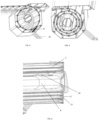
- each of the one or more curtain collapsible engaging means 9, 10 is hingedly and slidably mounted to said one or more sleeve elements 7, 8, respectively, such that as the rollable curtain 1 is retracted each of the one or more curtain collapsible engaging means 9, 10 gradually collapses and gradually slides along a groove provided on each of the one or more sleeve elements 7, 8 until reaching a totally collapsed position when the rollable curtain 1 is in a fully retracted position, as shown in FIG.
- each of the one or more curtain collapsible elements 9, 10 gradually rises and gradually slides in the opposite direction until reaching a totally raised position when the rollable curtain 1 is in a fully extended position, as shown in FIG. 2 .
- the housing box 5 comprises side walls 11, 12, each having inwardly extending continuous helical trackways 13, as shown in FIG. 5 , defining a rolling path, the helical trackways 13 being aligned with the channel portions of the side rails 3, 4 to receive the transverse adjacent panels 2 as they are translated forwardly into a retracted position.
- Utilization of the helical trackways 13 to store the cover in a retracted position enables extension and retraction of the cover free of excessive frictional resistance.
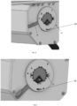
- At least one of the side walls 11, 12 of the housing box 5 comprises an opening 15.
- the housing box 5 further comprises an elongated opening 14, as shown in FIG. 1 , in top surface thereof, for the rollable curtain 1 to extend outwardly.
- the opening 14 has a sufficient width to accommodate the width of the rollable curtain 1.
- the housing box 5 may comprise one or more drainage pipe 16 arranged in the bottom, back or sides of housing box to drain out water and encourage air circulation, to minimize humidity and to avoid corrosion on the rollable curtain 1 while it is stored within housing box 5. Further, one or more anti-leaf system 27 may be present in the inner bottom and/or inner sides of the housing box 5 to prevent blockage of said drainage pipe 16. Additionally, it is also contemplated that the housing box 5 comprises overflow means 28, shown in Fig. 8 & 9 , arranged at each side wall of the housing box.
- the housing box 5 comprises a water level sensor, not shown.
- the transverse rotatable shaft 6 is hollow and is adapted to, optionally, coaxially, slidably and removably receive a torsion spring-loaded assembly 17 or an electric motor assembly 18, through said opening 15.
- the torsion spring-loaded assembly 17 comprises a torsion spring that tightens when the rollable curtain 1 is extended, and loosens upon retraction of the rollable curtain 1.
- the torsion spring stores energy during extension of the rollable curtain 1 and releases energy during retraction of the curtain in order to assist the user's operation.
- the torsion spring-loaded assembly 17 comprises a torsion spring, a first end section 17a comprising drive means 20 designed to internally engage the transverse rotatable shaft 6 for transmitting the torque force from the torsion spring to the transverse rotatable shaft 6, and a second end section 17b comprising engaging means 22 designed for engaging the torsion spring-loaded assembly 17 within opening 15.
- said second end section 17b may comprise a polygonal shaped element 26, such that a user, by means of a tool such as a wrench, is able to adjust the torsion spring tension.
- the rollable curtain 1 When semi-automatically operated, i.e., by means of the torsion spring-loaded assembly 17, the rollable curtain 1 may be manually locked and unlocked by means of a locking mechanism, not shown, provided on an end slat of the rollable curtain 1 to maintain a spring bias when the cover is in an extended position.
- the electric motor assembly 18 comprises an electric motor, a first end section 18a comprising drive means 21 designed to internally engage the transverse rotatable shaft 6 for transmitting the rotary force from the electric motor to the transverse rotatable shaft 6, and a second end section 18b comprising engaging means 23 designed for engaging the electric motor assembly 18 with the clamping system (24) at the side wall of the housing box.
- the electric motor is a conventional DC electric motor.
- drive means 20, 21 include engagement notches spaced about the outer circumferential surface thereof for inter-engagement with depending portions, designed to be in driving engagement with said gear means 20, 21, arranged on the inner surface of the transverse rotatable shaft 6.
- said engagement notches have a tapered shape, generally V-shape, or a U-shape to facilitate disengagement of the electric motor assembly 18 from the rotatable shaft 6 upon failure of the power system.
- the external profile of the drive means 20, 21 matches the clamping system (24) at the side wall of the housing box, such that a user can easily introduce the torsion spring-loaded assembly 17 or the electric motor assembly 18 through the opening 15 into the transverse rotatable shaft 6.
- the cover assembly of the present invention when comprising the electric motor assembly 18, is electrically operable to be moved between extended, semi-extended and retracted positions.
- the rollable curtain 1 can be stopped and locked at any spot by means of an auto locking mechanism.
- the drive means 21 is connected with the electric motor means by means of a gear comprised within the first section 18a, as shown in FIG. 7b , so that said first end section 18a is rotatable in a first direction of rotation, upon an "unwinding" actuation of the motor.
- the first end section 18a is rotatable in a second direction of rotation opposite the first direction, upon a "winding" actuation of the electric motor.
- the drive means 21 may be removable from said first section 18a such they can disengage from the electric motor assembly 18 and remain inside the shaft 6.
- the electric motor is driven by a smart-AI control circuit board 19 mounted on a side wall 11,12 of the housing box 5, as shown in FIG.12 .
- Said smart-AI controller circuit board 19 is preferably connected to the vehicle battery.
- a control panel means may be mounted on or adjacent the housing box 5 and/or in the truck cab and/or in the side rails and/or in the end slat.
- the electric motor assembly 18 may be remotely controlled by a remote controller or an app installed in a smartphone. Additionally, or alternatively, the electric motor may be operated by an actuator incorporated at the end slat.
- the rollable curtain 1 can thus be opened, closed, stopped and/or locked automatically at any spot.
- the cover assembly provides manual engagement and disengagement of the torsion spring-loaded assembly 17 or the electric motor assembly 18 by a user.
- One side wall 11, 12 of the housing box 5 includes a retaining mechanism 24 comprising a retaining member 25, that is selectively movable between a first position A in which a retaining member blocks removal of the torsion spring-loaded assembly 17 or the electric motor assembly 18, more specifically blocks the engaging means 22, 23 of the torsion spring-loaded assembly 17 or the electric motor assembly 18, respectively, as shown in FIG. 9 , and a second position B in which the retaining member does not block removal of the spring-loaded assembly 17 or the electric motor 18 assembly, as shown in FIG 8 .
- the retaining member 25 is selectively movable by means of a manual actuator 26, such that a user can easily engage/disengage the torsion spring-loaded assembly 17 or the electric motor assembly 18 without the need of tools or special knowledge.
- the manual actuator is a lever 26.
- Constructional elements of the electric motor assembly 18 and spring-loaded assembly 17 in combination with the configuration or design of the shaft 6 and opening 15 result in a sealed system once the electric motor assembly 18 or spring-loaded assembly 17 is inserted in the opening 15 and locked by means of said retaining member.
- the cover assembly may comprise a plurality of cable guiding elements 25, as shown in FIG. 11 , mounted to at least part of the plurality of adjacent transverse panels 2 and configured to receive cable wires therethrough for providing a wired connection to the cover assembly.
- the cover assembly of the invention may further comprise a plurality of electric elements arranged on the transverse panels or slats 2, including an end slat, such as light elements or sensors means connected by means of said wired connection. Said electric elements may be remotely controlled, as shown in FIG.11 .
Priority Applications (2)
| Application Number | Priority Date | Filing Date | Title |
|---|---|---|---|
| EP22185152.0A EP4306346A1 (de) | 2022-07-15 | 2022-07-15 | Abdeckungsanordnung für eine lkw-ladefläche |
| PCT/EP2023/068540 WO2024012953A1 (en) | 2022-07-15 | 2023-07-05 | Cover assembly for truck bed |
Applications Claiming Priority (1)
| Application Number | Priority Date | Filing Date | Title |
|---|---|---|---|
| EP22185152.0A EP4306346A1 (de) | 2022-07-15 | 2022-07-15 | Abdeckungsanordnung für eine lkw-ladefläche |
Publications (1)
| Publication Number | Publication Date |
|---|---|
| EP4306346A1 true EP4306346A1 (de) | 2024-01-17 |
Family
ID=82608677
Family Applications (1)
| Application Number | Title | Priority Date | Filing Date |
|---|---|---|---|
| EP22185152.0A Pending EP4306346A1 (de) | 2022-07-15 | 2022-07-15 | Abdeckungsanordnung für eine lkw-ladefläche |
Country Status (2)
| Country | Link |
|---|---|
| EP (1) | EP4306346A1 (de) |
| WO (1) | WO2024012953A1 (de) |
Citations (4)
| Publication number | Priority date | Publication date | Assignee | Title |
|---|---|---|---|---|
| US3092170A (en) * | 1959-07-22 | 1963-06-04 | William L Ellis | Automatic door |
| WO1990002056A1 (en) * | 1988-08-31 | 1990-03-08 | Romano Frank S | Cover assembly with spiral storage grooves |
| FR2824867A1 (fr) * | 2001-05-15 | 2002-11-22 | F P P Sa | Volet roulant comportant un guide en spirale pour son tablier |
| DE102015004859A1 (de) * | 2015-04-17 | 2016-10-20 | Eric Blumenstiel | Rollladen |
-
2022
- 2022-07-15 EP EP22185152.0A patent/EP4306346A1/de active Pending
-
2023
- 2023-07-05 WO PCT/EP2023/068540 patent/WO2024012953A1/en unknown
Patent Citations (4)
| Publication number | Priority date | Publication date | Assignee | Title |
|---|---|---|---|---|
| US3092170A (en) * | 1959-07-22 | 1963-06-04 | William L Ellis | Automatic door |
| WO1990002056A1 (en) * | 1988-08-31 | 1990-03-08 | Romano Frank S | Cover assembly with spiral storage grooves |
| FR2824867A1 (fr) * | 2001-05-15 | 2002-11-22 | F P P Sa | Volet roulant comportant un guide en spirale pour son tablier |
| DE102015004859A1 (de) * | 2015-04-17 | 2016-10-20 | Eric Blumenstiel | Rollladen |
Also Published As
| Publication number | Publication date |
|---|---|
| WO2024012953A1 (en) | 2024-01-18 |
Similar Documents
| Publication | Publication Date | Title |
|---|---|---|
| US6427749B1 (en) | Power-driven shutter assembly | |
| US4261614A (en) | Telescoping camper | |
| US9038531B1 (en) | Telescoping type cover for truck beds and the like | |
| JP2008044605A (ja) | 窓昇降装置により駆動されるウィンドウシェード | |
| CA2054531C (en) | Built-in awning for recreational vehicle | |
| US6006811A (en) | Veranda tent | |
| EP3767066B1 (de) | Steuergeräteanordnung für eine fensterjalousievorrichtung | |
| DE202004014652U1 (de) | Fahrzeugtür mit einem Fensterheber | |
| EP0489450B1 (de) | Tür- oder Fensterverschluss | |
| EP3625072B1 (de) | Verbesserungen an ausfahrbaren abdeckungen für fahrzeuge | |
| EP4306346A1 (de) | Abdeckungsanordnung für eine lkw-ladefläche | |
| WO2005082656A1 (de) | Kraftfahrzeugtür mit mehreren verstellbaren bauteilen | |
| US20220134851A1 (en) | Electric lift gate and vehicle | |
| US6318789B1 (en) | Automotive windshield screen device | |
| EP0887508B1 (de) | Raffstore mit verfahrbarer Wendeschiene | |
| WO2010136917A1 (de) | Elektrisch betreibbare rollo | |
| EP4309932A1 (de) | Bausätze für eine lkw-ladeflächenabdeckungsanordnung | |
| EP1105614B1 (de) | Fenster-abschirmvorrichtung und eine universelle befestigungs- und parallelführungsvorrichtung für eine fenster-abschirmvorrichtung | |
| WO2016063798A1 (ja) | ロールシェード装置 | |
| DE3225099A1 (de) | Verschlusseinrichtung | |
| CN213861816U (zh) | 电动尾箱盖和汽车 | |
| EP1698517B1 (de) | Laderaumabdeckung für ein Kraftfahrzeug | |
| BR9702708A (pt) | Persiana reversível motorizada | |
| EP1275546B1 (de) | Vorrichtung für angetriebene Vorhänge angeordnet an einem Kraftfahrzeug oder dergleichem | |
| DE2228915A1 (de) | Elektrisch angetriebene jalousie fuer verbundfenster |
Legal Events
| Date | Code | Title | Description |
|---|---|---|---|
| PUAI | Public reference made under article 153(3) epc to a published international application that has entered the european phase |
Free format text: ORIGINAL CODE: 0009012 |
|
| STAA | Information on the status of an ep patent application or granted ep patent |
Free format text: STATUS: THE APPLICATION HAS BEEN PUBLISHED |
|
| AK | Designated contracting states |
Kind code of ref document: A1 Designated state(s): AL AT BE BG CH CY CZ DE DK EE ES FI FR GB GR HR HU IE IS IT LI LT LU LV MC MK MT NL NO PL PT RO RS SE SI SK SM TR |