EP4306346A1 - Cover assembly for truck bed - Google Patents
Cover assembly for truck bed Download PDFInfo
- Publication number
- EP4306346A1 EP4306346A1 EP22185152.0A EP22185152A EP4306346A1 EP 4306346 A1 EP4306346 A1 EP 4306346A1 EP 22185152 A EP22185152 A EP 22185152A EP 4306346 A1 EP4306346 A1 EP 4306346A1
- Authority
- EP
- European Patent Office
- Prior art keywords
- cover assembly
- electric motor
- assembly
- housing box
- curtain
- Prior art date
- Legal status (The legal status is an assumption and is not a legal conclusion. Google has not performed a legal analysis and makes no representation as to the accuracy of the status listed.)
- Granted
Links
Images




Classifications
-
- B—PERFORMING OPERATIONS; TRANSPORTING
- B60—VEHICLES IN GENERAL
- B60J—WINDOWS, WINDSCREENS, NON-FIXED ROOFS, DOORS, OR SIMILAR DEVICES FOR VEHICLES; REMOVABLE EXTERNAL PROTECTIVE COVERINGS SPECIALLY ADAPTED FOR VEHICLES
- B60J7/00—Non-fixed roofs; Roofs with movable panels, e.g. rotary sunroofs
- B60J7/02—Non-fixed roofs; Roofs with movable panels, e.g. rotary sunroofs of sliding type, e.g. comprising guide shoes
- B60J7/06—Non-fixed roofs; Roofs with movable panels, e.g. rotary sunroofs of sliding type, e.g. comprising guide shoes with non-rigid element or elements
- B60J7/067—Non-fixed roofs; Roofs with movable panels, e.g. rotary sunroofs of sliding type, e.g. comprising guide shoes with non-rigid element or elements sliding and winding up
- B60J7/068—Non-fixed roofs; Roofs with movable panels, e.g. rotary sunroofs of sliding type, e.g. comprising guide shoes with non-rigid element or elements sliding and winding up for utility vehicles, e.g. of tarpaulin or roller-blind type
-
- B—PERFORMING OPERATIONS; TRANSPORTING
- B60—VEHICLES IN GENERAL
- B60J—WINDOWS, WINDSCREENS, NON-FIXED ROOFS, DOORS, OR SIMILAR DEVICES FOR VEHICLES; REMOVABLE EXTERNAL PROTECTIVE COVERINGS SPECIALLY ADAPTED FOR VEHICLES
- B60J7/00—Non-fixed roofs; Roofs with movable panels, e.g. rotary sunroofs
- B60J7/02—Non-fixed roofs; Roofs with movable panels, e.g. rotary sunroofs of sliding type, e.g. comprising guide shoes
- B60J7/04—Non-fixed roofs; Roofs with movable panels, e.g. rotary sunroofs of sliding type, e.g. comprising guide shoes with rigid plate-like element or elements, e.g. open roofs with harmonica-type folding rigid panels
- B60J7/041—Non-fixed roofs; Roofs with movable panels, e.g. rotary sunroofs of sliding type, e.g. comprising guide shoes with rigid plate-like element or elements, e.g. open roofs with harmonica-type folding rigid panels for utility vehicles, e.g. with slidable and foldable rigid panels
-
- B—PERFORMING OPERATIONS; TRANSPORTING
- B60—VEHICLES IN GENERAL
- B60J—WINDOWS, WINDSCREENS, NON-FIXED ROOFS, DOORS, OR SIMILAR DEVICES FOR VEHICLES; REMOVABLE EXTERNAL PROTECTIVE COVERINGS SPECIALLY ADAPTED FOR VEHICLES
- B60J7/00—Non-fixed roofs; Roofs with movable panels, e.g. rotary sunroofs
- B60J7/02—Non-fixed roofs; Roofs with movable panels, e.g. rotary sunroofs of sliding type, e.g. comprising guide shoes
- B60J7/04—Non-fixed roofs; Roofs with movable panels, e.g. rotary sunroofs of sliding type, e.g. comprising guide shoes with rigid plate-like element or elements, e.g. open roofs with harmonica-type folding rigid panels
- B60J7/057—Driving or actuating arrangements e.g. manually operated levers or knobs
-
- B—PERFORMING OPERATIONS; TRANSPORTING
- B60—VEHICLES IN GENERAL
- B60R—VEHICLES, VEHICLE FITTINGS, OR VEHICLE PARTS, NOT OTHERWISE PROVIDED FOR
- B60R16/00—Electric or fluid circuits specially adapted for vehicles and not otherwise provided for; Arrangement of elements of electric or fluid circuits specially adapted for vehicles and not otherwise provided for
- B60R16/02—Electric or fluid circuits specially adapted for vehicles and not otherwise provided for; Arrangement of elements of electric or fluid circuits specially adapted for vehicles and not otherwise provided for electric constitutive elements
- B60R16/023—Electric or fluid circuits specially adapted for vehicles and not otherwise provided for; Arrangement of elements of electric or fluid circuits specially adapted for vehicles and not otherwise provided for electric constitutive elements for transmission of signals between vehicle parts or subsystems
- B60R16/0231—Circuits relating to the driving or the functioning of the vehicle
-
- B—PERFORMING OPERATIONS; TRANSPORTING
- B60—VEHICLES IN GENERAL
- B60Y—INDEXING SCHEME RELATING TO ASPECTS CROSS-CUTTING VEHICLE TECHNOLOGY
- B60Y2200/00—Type of vehicle
- B60Y2200/10—Road Vehicles
- B60Y2200/14—Trucks; Load vehicles, Busses
-
- B—PERFORMING OPERATIONS; TRANSPORTING
- B60—VEHICLES IN GENERAL
- B60Y—INDEXING SCHEME RELATING TO ASPECTS CROSS-CUTTING VEHICLE TECHNOLOGY
- B60Y2400/00—Special features of vehicle units
- B60Y2400/40—Actuators for moving a controlled member
- B60Y2400/405—Electric motors actuators
Definitions
- the invention relates to a cover assembly for the truck bed of a pick-up type vehicle, and in particular to a cover assembly comprising a housing box for receiving and storing a rollable curtain, said housing box being configured for the rollable curtain to be manually operated by a user and adapted to detachably receive a torsion spring or an electric motor, such that the rollable curtain can be optionally adapted to be semi-automatically or automatically operated.
- retractable roll-up truck bed covers with open bed pickup trucks to provide security and protection for cargo items carried within the truck bed is well known.
- Conventional retractable roll-up truck bed covers commonly include a plurality of individual slats hingedly connected to form a slat array. The hinged connection of individual slats enables the slat array to form a continuous cover that, once mounted in a pair of side rails, can be either completely or partially extended or retracted and stored in a rolled-up configuration inside a housing.
- roll-up covers with a spring-loaded shaft which aids the user upon winding of the curtain.
- the function of this type of roll up covers is absolutely associated with the spring, such that in case of spring failure the roll-up covers cannot be operated. Also, this type of roll-up covers cannot be converted to manual or electric motor version of the cover.
- roll-up covers with helical trackways or spring-loaded shafts comprising an electric motor mounted on an auxiliary shaft inside the housing or in a position outside the housing box.
- an electric motor mounted on an auxiliary shaft inside the housing or in a position outside the housing box.
- this type of roll-up covers cannot be converted to a manual or spring assisted version of the cover.
- a cover assembly for a pickup truck bed comprises a rollable curtain formed of a plurality of transverse adjacent panels or slats hingedly linked to one another and guided along channel portions of a pair of side rails adapted to be mounted on upper portions of the side walls of the truck bed.
- the cover assembly comprises a housing box for receiving and storing the rollable curtain.
- Said housing comprising a transverse rotatable shaft mounted therein and one or more curtain collapsible engaging means, each mounted to one or more sleeve elements, for transforming the rotational movement of the shaft 6 into a linear motion of the rollable curtain 1, in an evenly distributed manner along the whole width of the rollable curtain.
- the housing box for storing the rollable curtain has side walls comprising helical trackways to help guide the rollable curtain free of excessive frictional resistance upon extending or retracting the same.
- the rotatable shaft and a clamping system at a side wall of the housing box are adapted to slidably and removably receive a torsion spring-loaded assembly or an electric motor assembly, such that a user can easily turn a manually operated cover assembly into a semi-automated or automated cover assembly and vice versa, with no tools or specific knowledge.
- the cover assembly of the invention is shown installed upon an existing conventional pickup truck, the rollable curtain 1 comprising a plurality of transverse adjacent panels or slats 2 which extend laterally across the pickup truck bed and are hingedly linked to one another.
- a pair of side rails 3, 4 are disposed in parallel relation to one another on upper portions of the side walls of the truck bed, respectively, said side rails 3, 4 comprising channel portions for guiding the end portions of the transverse adjacent panels 2.
- a housing box 5 adapted to be mounted at the forward end of the truck bed for receiving and storing the rollable curtain 1, is shown.
- Said housing box 5 comprising a transverse rotatable shaft 6 mounted therein.
- the transverse rotatable shaft 6 has a polygonal shape, for example a hexagonal shape.
- One or more sleeve elements 7, 8 are mounted on said transverse rotatable shaft 6 for receiving one or more collapsible curtain engaging means 9, 10, each mounted to said one or more sleeve elements 7, 8, respectively, and designed to engage an inner end of the rollable curtain 1 and to transform the rotational movement of the shaft 6 into a linear motion of the rollable curtain 1.
- Linear is understood to mean that the rollable curtain describes a line that can be straight or curved.
- Said one or more collapsible curtain engaging elements 9, 10 will ride along in engagement with the rollable curtain 1, gradually collapse as the rollable curtain 1 is retracted and gradually rise as the rollable curtain 1 is extended.
- each of the one or more curtain collapsible engaging means 9, 10 is hingedly and slidably mounted to said one or more sleeve elements 7, 8, respectively, such that as the rollable curtain 1 is retracted each of the one or more curtain collapsible engaging means 9, 10 gradually collapses and gradually slides along a groove provided on each of the one or more sleeve elements 7, 8 until reaching a totally collapsed position when the rollable curtain 1 is in a fully retracted position, as shown in FIG.
- each of the one or more curtain collapsible elements 9, 10 gradually rises and gradually slides in the opposite direction until reaching a totally raised position when the rollable curtain 1 is in a fully extended position, as shown in FIG. 2 .
- the housing box 5 comprises side walls 11, 12, each having inwardly extending continuous helical trackways 13, as shown in FIG. 5 , defining a rolling path, the helical trackways 13 being aligned with the channel portions of the side rails 3, 4 to receive the transverse adjacent panels 2 as they are translated forwardly into a retracted position.
- Utilization of the helical trackways 13 to store the cover in a retracted position enables extension and retraction of the cover free of excessive frictional resistance.
- At least one of the side walls 11, 12 of the housing box 5 comprises an opening 15.
- the housing box 5 further comprises an elongated opening 14, as shown in FIG. 1 , in top surface thereof, for the rollable curtain 1 to extend outwardly.
- the opening 14 has a sufficient width to accommodate the width of the rollable curtain 1.
- the housing box 5 may comprise one or more drainage pipe 16 arranged in the bottom, back or sides of housing box to drain out water and encourage air circulation, to minimize humidity and to avoid corrosion on the rollable curtain 1 while it is stored within housing box 5. Further, one or more anti-leaf system 27 may be present in the inner bottom and/or inner sides of the housing box 5 to prevent blockage of said drainage pipe 16. Additionally, it is also contemplated that the housing box 5 comprises overflow means 28, shown in Fig. 8 & 9 , arranged at each side wall of the housing box.
- the housing box 5 comprises a water level sensor, not shown.
- the transverse rotatable shaft 6 is hollow and is adapted to, optionally, coaxially, slidably and removably receive a torsion spring-loaded assembly 17 or an electric motor assembly 18, through said opening 15.
- the torsion spring-loaded assembly 17 comprises a torsion spring that tightens when the rollable curtain 1 is extended, and loosens upon retraction of the rollable curtain 1.
- the torsion spring stores energy during extension of the rollable curtain 1 and releases energy during retraction of the curtain in order to assist the user's operation.
- the torsion spring-loaded assembly 17 comprises a torsion spring, a first end section 17a comprising drive means 20 designed to internally engage the transverse rotatable shaft 6 for transmitting the torque force from the torsion spring to the transverse rotatable shaft 6, and a second end section 17b comprising engaging means 22 designed for engaging the torsion spring-loaded assembly 17 within opening 15.
- said second end section 17b may comprise a polygonal shaped element 26, such that a user, by means of a tool such as a wrench, is able to adjust the torsion spring tension.
- the rollable curtain 1 When semi-automatically operated, i.e., by means of the torsion spring-loaded assembly 17, the rollable curtain 1 may be manually locked and unlocked by means of a locking mechanism, not shown, provided on an end slat of the rollable curtain 1 to maintain a spring bias when the cover is in an extended position.
- the electric motor assembly 18 comprises an electric motor, a first end section 18a comprising drive means 21 designed to internally engage the transverse rotatable shaft 6 for transmitting the rotary force from the electric motor to the transverse rotatable shaft 6, and a second end section 18b comprising engaging means 23 designed for engaging the electric motor assembly 18 with the clamping system (24) at the side wall of the housing box.
- the electric motor is a conventional DC electric motor.
- drive means 20, 21 include engagement notches spaced about the outer circumferential surface thereof for inter-engagement with depending portions, designed to be in driving engagement with said gear means 20, 21, arranged on the inner surface of the transverse rotatable shaft 6.
- said engagement notches have a tapered shape, generally V-shape, or a U-shape to facilitate disengagement of the electric motor assembly 18 from the rotatable shaft 6 upon failure of the power system.
- the external profile of the drive means 20, 21 matches the clamping system (24) at the side wall of the housing box, such that a user can easily introduce the torsion spring-loaded assembly 17 or the electric motor assembly 18 through the opening 15 into the transverse rotatable shaft 6.
- the cover assembly of the present invention when comprising the electric motor assembly 18, is electrically operable to be moved between extended, semi-extended and retracted positions.
- the rollable curtain 1 can be stopped and locked at any spot by means of an auto locking mechanism.
- the drive means 21 is connected with the electric motor means by means of a gear comprised within the first section 18a, as shown in FIG. 7b , so that said first end section 18a is rotatable in a first direction of rotation, upon an "unwinding" actuation of the motor.
- the first end section 18a is rotatable in a second direction of rotation opposite the first direction, upon a "winding" actuation of the electric motor.
- the drive means 21 may be removable from said first section 18a such they can disengage from the electric motor assembly 18 and remain inside the shaft 6.
- the electric motor is driven by a smart-AI control circuit board 19 mounted on a side wall 11,12 of the housing box 5, as shown in FIG.12 .
- Said smart-AI controller circuit board 19 is preferably connected to the vehicle battery.
- a control panel means may be mounted on or adjacent the housing box 5 and/or in the truck cab and/or in the side rails and/or in the end slat.
- the electric motor assembly 18 may be remotely controlled by a remote controller or an app installed in a smartphone. Additionally, or alternatively, the electric motor may be operated by an actuator incorporated at the end slat.
- the rollable curtain 1 can thus be opened, closed, stopped and/or locked automatically at any spot.
- the cover assembly provides manual engagement and disengagement of the torsion spring-loaded assembly 17 or the electric motor assembly 18 by a user.
- One side wall 11, 12 of the housing box 5 includes a retaining mechanism 24 comprising a retaining member 25, that is selectively movable between a first position A in which a retaining member blocks removal of the torsion spring-loaded assembly 17 or the electric motor assembly 18, more specifically blocks the engaging means 22, 23 of the torsion spring-loaded assembly 17 or the electric motor assembly 18, respectively, as shown in FIG. 9 , and a second position B in which the retaining member does not block removal of the spring-loaded assembly 17 or the electric motor 18 assembly, as shown in FIG 8 .
- the retaining member 25 is selectively movable by means of a manual actuator 26, such that a user can easily engage/disengage the torsion spring-loaded assembly 17 or the electric motor assembly 18 without the need of tools or special knowledge.
- the manual actuator is a lever 26.
- Constructional elements of the electric motor assembly 18 and spring-loaded assembly 17 in combination with the configuration or design of the shaft 6 and opening 15 result in a sealed system once the electric motor assembly 18 or spring-loaded assembly 17 is inserted in the opening 15 and locked by means of said retaining member.
- the cover assembly may comprise a plurality of cable guiding elements 25, as shown in FIG. 11 , mounted to at least part of the plurality of adjacent transverse panels 2 and configured to receive cable wires therethrough for providing a wired connection to the cover assembly.
- the cover assembly of the invention may further comprise a plurality of electric elements arranged on the transverse panels or slats 2, including an end slat, such as light elements or sensors means connected by means of said wired connection. Said electric elements may be remotely controlled, as shown in FIG.11 .
Landscapes
- Engineering & Computer Science (AREA)
- Mechanical Engineering (AREA)
- Operating, Guiding And Securing Of Roll- Type Closing Members (AREA)
- Vehicle Step Arrangements And Article Storage (AREA)
Abstract
Description
- The invention relates to a cover assembly for the truck bed of a pick-up type vehicle, and in particular to a cover assembly comprising a housing box for receiving and storing a rollable curtain, said housing box being configured for the rollable curtain to be manually operated by a user and adapted to detachably receive a torsion spring or an electric motor, such that the rollable curtain can be optionally adapted to be semi-automatically or automatically operated.
- The design and use of retractable roll-up truck bed covers with open bed pickup trucks to provide security and protection for cargo items carried within the truck bed is well known. Conventional retractable roll-up truck bed covers commonly include a plurality of individual slats hingedly connected to form a slat array. The hinged connection of individual slats enables the slat array to form a continuous cover that, once mounted in a pair of side rails, can be either completely or partially extended or retracted and stored in a rolled-up configuration inside a housing.
- There are several types of known roll-up covers. There are roll-up covers manually operated in both directions, with no spring or electric motor, that comprise helical trackways, which cause the cover to assume a substantially rolled position. However, this type of roll-up covers have the disadvantage of not rolling up straight if the user-applied application force is not applied evenly along the width of the cover, causing the cover to be crooked. Also, this type of roll-up covers cannot be converted to a spring or electric motor assisted cover.
- There are also roll-up covers with a spring-loaded shaft which aids the user upon winding of the curtain. The function of this type of roll up covers is absolutely associated with the spring, such that in case of spring failure the roll-up covers cannot be operated. Also, this type of roll-up covers cannot be converted to manual or electric motor version of the cover.
- Further, there are roll-up covers with helical trackways or spring-loaded shafts comprising an electric motor mounted on an auxiliary shaft inside the housing or in a position outside the housing box. In case of an emergency or electric motor failure, there are mechanisms to allow the user to operate the roll up cover manually. However, there still remains the need for the electric motor to be replaced as this roll-up cover cannot be operated manually in the long term. Also, this type of roll-up covers cannot be converted to a manual or spring assisted version of the cover.
- Hence, there remains a need for a cover system that can be easily adapted by a user, with no tools or specific knowledge, from a manually operated cover to a spring or an electric motor assisted cover and vice versa, and wherein the spring and/or electric motor can be easily replaced in case of malfunction or failure of the same.
- In accordance with the invention a cover assembly for a pickup truck bed is provided. The cover assembly comprises a rollable curtain formed of a plurality of transverse adjacent panels or slats hingedly linked to one another and guided along channel portions of a pair of side rails adapted to be mounted on upper portions of the side walls of the truck bed.
- According to one aspect of the invention, the cover assembly comprises a housing box for receiving and storing the rollable curtain. Said housing comprising a transverse rotatable shaft mounted therein and one or more curtain collapsible engaging means, each mounted to one or more sleeve elements, for transforming the rotational movement of the
shaft 6 into a linear motion of therollable curtain 1, in an evenly distributed manner along the whole width of the rollable curtain. - According to another aspect of the invention, the housing box for storing the rollable curtain has side walls comprising helical trackways to help guide the rollable curtain free of excessive frictional resistance upon extending or retracting the same.
- According to yet another aspect of the invention, the rotatable shaft and a clamping system at a side wall of the housing box are adapted to slidably and removably receive a torsion spring-loaded assembly or an electric motor assembly, such that a user can easily turn a manually operated cover assembly into a semi-automated or automated cover assembly and vice versa, with no tools or specific knowledge.
- A more complete understanding of our invention and its advantages will be apparent from the detailed description taken in conjunction with the accompanying drawings in which:
-
FIG. 1 is a perspective schematic view of a cover assembly in accordance with the invention installed onto a conventional pickup truck bed. -
FIG. 2 is a cross sectional side view of a cover assembly in accordance with the invention, wherein the rollable curtain is in a fully extended position. -
FIG. 3 is a cross sectional side view of a cover assembly in accordance with the invention, wherein the rollable curtain is in a partially extended position. -
FIG. 4 is a cross sectional side perspective view of the housing box in accordance with the invention, wherein the rollable curtain is in a fully retracted position. -
FIG. 5 is a cross sectional front view of the housing box in accordance with the invention, wherein the rollable curtain is in a fully retracted position. -
FIG. 6a is a perspective view of a cover assembly, showing a torsion spring-loaded assembly according to an embodiment of the invention. -
FIG. 6b is a detail view of the second end portion of the torsion spring-loaded assembly ofFIG. 6a . -
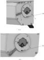
FIG. 7a is a perspective view of a cover assembly, showing an electric motor assembly according to an embodiment of the invention. -
FIG. 7b is a detail exploded view of the first end portion of the electric motor assembly ofFIG. 7a . -
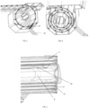
FIGs. 8 is a perspective view showing the retaining mechanism of the housing box in an unlocked arrangement, when comprising a torsion spring-loaded assembly or an electric motor assembly according to embodiments of the invention. -
FIGs. 9 is a perspective view showing the retaining mechanism of the housing box in a locked arrangement, when comprising a torsion spring-loaded assembly or an electric motor assembly according to embodiments of the invention. -
FIG. 10 is a side perspective view of the housing box according to an embodiment of the present invention. -
FIG. 11 is a partial top perspective view of the rollable curtain according to an embodiment of the present invention. -
FIG. 12 shows a wiring diagram of the cover assembly according to an embodiment of the invention. - Referring now to the drawings and specifically
FIG. 1 , the cover assembly of the invention is shown installed upon an existing conventional pickup truck, therollable curtain 1 comprising a plurality of transverse adjacent panels orslats 2 which extend laterally across the pickup truck bed and are hingedly linked to one another. A pair ofside rails 3, 4 are disposed in parallel relation to one another on upper portions of the side walls of the truck bed, respectively, saidside rails 3, 4 comprising channel portions for guiding the end portions of the transverseadjacent panels 2. - Referring to
FIGs. 2 and3 , ahousing box 5 adapted to be mounted at the forward end of the truck bed for receiving and storing therollable curtain 1, is shown. Saidhousing box 5 comprising a transverserotatable shaft 6 mounted therein. - According to an embodiment of the invention, the transverse
rotatable shaft 6 has a polygonal shape, for example a hexagonal shape. - One or more
sleeve elements rotatable shaft 6 for receiving one or more collapsiblecurtain engaging means sleeve elements rollable curtain 1 and to transform the rotational movement of theshaft 6 into a linear motion of therollable curtain 1. - "Linear" is understood to mean that the rollable curtain describes a line that can be straight or curved.
- Said one or more collapsible
curtain engaging elements rollable curtain 1, gradually collapse as therollable curtain 1 is retracted and gradually rise as therollable curtain 1 is extended. - Thus, as a user manually guides the
rollable curtain 1 towards a retracted or an extended position, the linear motion of therollable curtain 1 is transformed into a rotational movement of the of the transverserotatable shaft 6 by means of said one or more collapsiblecurtain engaging elements - In a preferred embodiment of the present invention, each of the one or more curtain collapsible engaging
means more sleeve elements rollable curtain 1 is retracted each of the one or more curtain collapsibleengaging means sleeve elements rollable curtain 1 is in a fully retracted position, as shown inFIG. 4 , and such that as therollable curtain 1 is extended each of the one or more curtaincollapsible elements rollable curtain 1 is in a fully extended position, as shown inFIG. 2 . - Referring to
FIG. 5 , thehousing box 5 comprisesside walls helical trackways 13, as shown inFIG. 5 , defining a rolling path, thehelical trackways 13 being aligned with the channel portions of theside rails 3, 4 to receive the transverseadjacent panels 2 as they are translated forwardly into a retracted position. - Utilization of the
helical trackways 13 to store the cover in a retracted position enables extension and retraction of the cover free of excessive frictional resistance. - At least one of the
side walls housing box 5 comprises an opening 15. - According to the invention, the
housing box 5 further comprises anelongated opening 14, as shown inFIG. 1 , in top surface thereof, for therollable curtain 1 to extend outwardly. - The
opening 14 has a sufficient width to accommodate the width of therollable curtain 1. - The
housing box 5 may comprise one ormore drainage pipe 16 arranged in the bottom, back or sides of housing box to drain out water and encourage air circulation, to minimize humidity and to avoid corrosion on therollable curtain 1 while it is stored withinhousing box 5. Further, one or moreanti-leaf system 27 may be present in the inner bottom and/or inner sides of thehousing box 5 to prevent blockage of saiddrainage pipe 16. Additionally, it is also contemplated that thehousing box 5 comprises overflow means 28, shown inFig. 8 & 9 , arranged at each side wall of the housing box. - It is also contemplated that the
housing box 5 comprises a water level sensor, not shown. - According to an embodiment of the present invention, the transverse
rotatable shaft 6 is hollow and is adapted to, optionally, coaxially, slidably and removably receive a torsion spring-loadedassembly 17 or anelectric motor assembly 18, through saidopening 15. - The torsion spring-loaded
assembly 17 comprises a torsion spring that tightens when therollable curtain 1 is extended, and loosens upon retraction of therollable curtain 1. - The torsion spring stores energy during extension of the
rollable curtain 1 and releases energy during retraction of the curtain in order to assist the user's operation. - The torsion spring-loaded
assembly 17 comprises a torsion spring, afirst end section 17a comprising drive means 20 designed to internally engage the transverserotatable shaft 6 for transmitting the torque force from the torsion spring to the transverserotatable shaft 6, and asecond end section 17b comprising engaging means 22 designed for engaging the torsion spring-loadedassembly 17 withinopening 15. Further, saidsecond end section 17b may comprise a polygonal shapedelement 26, such that a user, by means of a tool such as a wrench, is able to adjust the torsion spring tension. - When semi-automatically operated, i.e., by means of the torsion spring-loaded
assembly 17, therollable curtain 1 may be manually locked and unlocked by means of a locking mechanism, not shown, provided on an end slat of therollable curtain 1 to maintain a spring bias when the cover is in an extended position. - In an embodiment, the
electric motor assembly 18 comprises an electric motor, afirst end section 18a comprising drive means 21 designed to internally engage the transverserotatable shaft 6 for transmitting the rotary force from the electric motor to the transverserotatable shaft 6, and asecond end section 18b comprising engaging means 23 designed for engaging theelectric motor assembly 18 with the clamping system (24) at the side wall of the housing box. - In a preferred embodiment of the invention, the electric motor is a conventional DC electric motor.
- As shown in
FIGs. 6a, 7a and 7b , drive means 20, 21 include engagement notches spaced about the outer circumferential surface thereof for inter-engagement with depending portions, designed to be in driving engagement with said gear means 20, 21, arranged on the inner surface of the transverserotatable shaft 6. - In an embodiment of the present invention, said engagement notches have a tapered shape, generally V-shape, or a U-shape to facilitate disengagement of the
electric motor assembly 18 from therotatable shaft 6 upon failure of the power system. - The external profile of the drive means 20, 21 matches the clamping system (24) at the side wall of the housing box, such that a user can easily introduce the torsion spring-loaded
assembly 17 or theelectric motor assembly 18 through theopening 15 into the transverserotatable shaft 6. - In operation, the cover assembly of the present invention, when comprising the
electric motor assembly 18, is electrically operable to be moved between extended, semi-extended and retracted positions. Therollable curtain 1 can be stopped and locked at any spot by means of an auto locking mechanism. - The drive means 21 is connected with the electric motor means by means of a gear comprised within the
first section 18a, as shown inFIG. 7b , so that saidfirst end section 18a is rotatable in a first direction of rotation, upon an "unwinding" actuation of the motor. Thefirst end section 18a is rotatable in a second direction of rotation opposite the first direction, upon a "winding" actuation of the electric motor. - In contemplated embodiments of the present invention, the drive means 21 may be removable from said
first section 18a such they can disengage from theelectric motor assembly 18 and remain inside theshaft 6. - The electric motor is driven by a smart-AI
control circuit board 19 mounted on aside wall housing box 5, as shown inFIG.12 . Said smart-AIcontroller circuit board 19 is preferably connected to the vehicle battery. - A control panel means, not shown, may be mounted on or adjacent the
housing box 5 and/or in the truck cab and/or in the side rails and/or in the end slat. - The
electric motor assembly 18 may be remotely controlled by a remote controller or an app installed in a smartphone. Additionally, or alternatively, the electric motor may be operated by an actuator incorporated at the end slat. Therollable curtain 1 can thus be opened, closed, stopped and/or locked automatically at any spot. - Referring now to
FIGs. 8 and 9 , the cover assembly provides manual engagement and disengagement of the torsion spring-loadedassembly 17 or theelectric motor assembly 18 by a user. - One
side wall housing box 5 includes aretaining mechanism 24 comprising a retainingmember 25, that is selectively movable between a first position A in which a retaining member blocks removal of the torsion spring-loadedassembly 17 or theelectric motor assembly 18, more specifically blocks the engagingmeans assembly 17 or theelectric motor assembly 18, respectively, as shown inFIG. 9 , and a second position B in which the retaining member does not block removal of the spring-loadedassembly 17 or theelectric motor 18 assembly, as shown inFIG 8 . The retainingmember 25 is selectively movable by means of amanual actuator 26, such that a user can easily engage/disengage the torsion spring-loadedassembly 17 or theelectric motor assembly 18 without the need of tools or special knowledge. - In one embodiment of the invention, as shown in
FIG.9 , the manual actuator is alever 26. - Constructional elements of the
electric motor assembly 18 and spring-loadedassembly 17 in combination with the configuration or design of theshaft 6 andopening 15 result in a sealed system once theelectric motor assembly 18 or spring-loadedassembly 17 is inserted in theopening 15 and locked by means of said retaining member. - In any of the embodiments of the invention, the cover assembly may comprise a plurality of
cable guiding elements 25, as shown inFIG. 11 , mounted to at least part of the plurality of adjacenttransverse panels 2 and configured to receive cable wires therethrough for providing a wired connection to the cover assembly. - The cover assembly of the invention may further comprise a plurality of electric elements arranged on the transverse panels or
slats 2, including an end slat, such as light elements or sensors means connected by means of said wired connection. Said electric elements may be remotely controlled, as shown inFIG.11 . - While the embodiments have been described in detail in the description, the same is to be considered illustrative and not restrictive in character, being understood that it would be obvious to those skilled in the art that various other changes and modifications may be made without departing from the scope of the disclosure.
Claims (15)
- A cover assembly for the truck bed of a pick-up type vehicle, said cover assembly comprising:a rollable curtain (1) comprising a plurality of transverse adjacent panels (2) hingedly linked to one another;a pair of side rails (3, 4) adapted to be mounted on upper portions of the side walls of the truck bed and comprising guiding channels for guiding the end portions of the transverse adjacent panels (2);a housing box (5) adapted to be mounted at the forward end of the truck bed for receiving and storing the rollable curtain (1),wherein the housing box (5) comprises:a transverse rotatable shaft (6) mounted within the housing box (5);one or more sleeve elements (7, 8) mounted on said transverse rotatable shaft (6);one or more collapsible curtain engaging means (9, 10) each mounted to said one or more sleeve elements (7, 8), respectively, and designed to engage an inner end of the rollable curtain (1) and to transform the rotational movement of the shaft (6) into a linear motion of the rollable curtain (1); andside walls (11, 12), each having inwardly extending continuous helical trackways (13) defining a rolling path, the helical trackways being aligned with the guiding channels of the side rails (3, 4) to receive the transverse adjacent panels (2) as they are translated forwardly into a retracted position;
- The cover assembly according to claim 1, wherein said one or more collapsible curtain engaging means (9, 10) are hingedly and slidably mounted to said one or more sleeve elements (7, 8), respectively.
- The cover assembly according to of claims 1 or 2, wherein at least one of the side walls (11, 12) of the housing box (5) comprises an opening (15).
- The cover assembly according to the preceding claims, wherein the transverse rotatable shaft (6) has a polygonal shape, preferably a hexagonal shape.
- The cover assembly according to the preceding claims, wherein the transverse rotatable shaft (6) is hollow.
- The cover assembly according to claims 3 and 5, wherein the transverse rotatable shaft (6) and a clamping system (24) at a side wall of the housing box are adapted to slidably and removably receive a torsion spring-loaded assembly (17).
- The cover assembly according to claims 1 and 6, wherein the cover assembly further comprises a torsion spring-loaded assembly (17).
- The cover assembly according to claims 3 and 5, wherein the transverse rotatable shaft (6) and a clamping system (24) at a side wall of the housing box are adapted to slidably and removably receive an electric motor assembly (18).
- The cover assembly according to claims 1 and 8, wherein the cover assembly further comprises an electric motor assembly (18).
- The cover assembly according to claim 9, wherein the electric motor assembly (18) is driven by a smart-AI controller circuit board (19) mounted on the housing box (5).
- The cover assembly according to claims 9 or 10, wherein the electric motor assembly (18) is configured to be remotely controlled by means of said smart-AI controller circuit board (19).
- The cover assembly according to claim 11, wherein the electric motor assembly (18) is remotely controlled by a remote controller or an app installed in a smartphone.
- The cover assembly according to claims 7 and 9, wherein the torsion spring-loaded assembly (17) and the electric motor assembly (18) comprise drive means (20, 21), mounted for rotation, for internally engaging the transverse rotatable shaft (6).
- The cover system according to claims 7 to 13, wherein the torsion spring-loaded assembly (17) and the electric motor assembly (18) comprise engaging means (22, 23) for engaging a side wall (11, 12) of the housing box (5).
- The cover system according to claims 7 to 14, wherein a side wall (11, 12) of the housing box (5) includes a retaining mechanism (24) comprising a retaining member (25), that is selectively movable between a first position in which a retaining member blocks removal of the torsion spring-loaded assembly (17) or the electric motor assembly (18), and a second position in which the retaining member does not block removal of the spring-loaded assembly (17) or the electric motor (18) assembly, respectively.
Priority Applications (8)
| Application Number | Priority Date | Filing Date | Title |
|---|---|---|---|
| EP22185152.0A EP4306346B1 (en) | 2022-07-15 | 2022-07-15 | Cover assembly for truck bed |
| PCT/EP2023/068540 WO2024012953A1 (en) | 2022-07-15 | 2023-07-05 | Cover assembly for truck bed |
| AU2023308027A AU2023308027B2 (en) | 2022-07-15 | 2023-07-05 | Cover assembly for truck bed |
| KR1020257004306A KR20250036203A (en) | 2022-07-15 | 2023-07-05 | Cover assembly for truck bed |
| US18/994,482 US20260034869A1 (en) | 2022-07-15 | 2023-07-05 | Cover assembly for truck bed |
| CA3261446A CA3261446A1 (en) | 2022-07-15 | 2023-07-05 | Cover assembly for truck bed |
| CN202380053317.9A CN119546470A (en) | 2022-07-15 | 2023-07-05 | Protective cover assembly for truck bed |
| ZA2025/00612A ZA202500612B (en) | 2022-07-15 | 2025-01-17 | Cover assembly for truck bed |
Applications Claiming Priority (1)
| Application Number | Priority Date | Filing Date | Title |
|---|---|---|---|
| EP22185152.0A EP4306346B1 (en) | 2022-07-15 | 2022-07-15 | Cover assembly for truck bed |
Publications (3)
| Publication Number | Publication Date |
|---|---|
| EP4306346A1 true EP4306346A1 (en) | 2024-01-17 |
| EP4306346C0 EP4306346C0 (en) | 2026-02-18 |
| EP4306346B1 EP4306346B1 (en) | 2026-02-18 |
Family
ID=82608677
Family Applications (1)
| Application Number | Title | Priority Date | Filing Date |
|---|---|---|---|
| EP22185152.0A Active EP4306346B1 (en) | 2022-07-15 | 2022-07-15 | Cover assembly for truck bed |
Country Status (7)
| Country | Link |
|---|---|
| US (1) | US20260034869A1 (en) |
| EP (1) | EP4306346B1 (en) |
| KR (1) | KR20250036203A (en) |
| CN (1) | CN119546470A (en) |
| CA (1) | CA3261446A1 (en) |
| WO (1) | WO2024012953A1 (en) |
| ZA (1) | ZA202500612B (en) |
Citations (4)
| Publication number | Priority date | Publication date | Assignee | Title |
|---|---|---|---|---|
| US3092170A (en) * | 1959-07-22 | 1963-06-04 | William L Ellis | Automatic door |
| WO1990002056A1 (en) * | 1988-08-31 | 1990-03-08 | Romano Frank S | Cover assembly with spiral storage grooves |
| FR2824867A1 (en) * | 2001-05-15 | 2002-11-22 | F P P Sa | Roller blind comprises shutter, composed of series of laths, wound by driving mechanism and guided by guide elements in spiral path |
| DE102015004859A1 (en) * | 2015-04-17 | 2016-10-20 | Eric Blumenstiel | shutters |
Family Cites Families (12)
| Publication number | Priority date | Publication date | Assignee | Title |
|---|---|---|---|---|
| US4563034A (en) * | 1983-05-19 | 1986-01-07 | Lamb Joe H | Retractable truck bed cover for pick-ups |
| US4611848A (en) * | 1985-04-15 | 1986-09-16 | Romano Frank S | Sliding cover assembly for open body trucks |
| DE102005049584A1 (en) * | 2005-10-17 | 2007-05-10 | Efaflex Inzeniring D.O.O. | High-speed industrial rolling gate |
| US20080121353A1 (en) * | 2006-11-16 | 2008-05-29 | Detmer Brandon J | Manual roller shade having clutch mechanism, chain guide and universal mounting |
| US9834076B2 (en) * | 2015-03-25 | 2017-12-05 | A.R.E. Accessories, Llc | Dual action truck bed cover |
| CN104775742B (en) * | 2015-04-03 | 2016-10-26 | 昆明海顿自动门业有限公司 | A kind of universal roll-type window or door |
| US10737563B2 (en) * | 2018-01-09 | 2020-08-11 | Tectum Holdings Inc. | Bias regulated rolling truck bed cover |
| US20190292849A1 (en) * | 2018-03-21 | 2019-09-26 | Tti (Macao Commercial Offshore) Limited | Manual to motorized convertible roller blinds |
| CN212837510U (en) * | 2020-05-15 | 2021-03-30 | 无锡林特门业科技有限公司 | Automatic door driven by middle shaft |
| CN213565388U (en) * | 2020-11-23 | 2021-06-29 | 瑞安市祥瑞亿业汽车用品厂 | Roller shutter door for pickup truck |
| WO2023272364A1 (en) * | 2021-06-28 | 2023-01-05 | Keko Acessórios S/A | Retractable cover for vehicles with a bed and the like |
| CN113417557B (en) * | 2021-07-29 | 2024-10-18 | 青岛拉斐特智能装备科技有限公司 | Mute roller shutter door connected by folding arm structure |
-
2022
- 2022-07-15 EP EP22185152.0A patent/EP4306346B1/en active Active
-
2023
- 2023-07-05 WO PCT/EP2023/068540 patent/WO2024012953A1/en not_active Ceased
- 2023-07-05 CA CA3261446A patent/CA3261446A1/en active Pending
- 2023-07-05 US US18/994,482 patent/US20260034869A1/en active Pending
- 2023-07-05 KR KR1020257004306A patent/KR20250036203A/en active Pending
- 2023-07-05 CN CN202380053317.9A patent/CN119546470A/en active Pending
-
2025
- 2025-01-17 ZA ZA2025/00612A patent/ZA202500612B/en unknown
Patent Citations (4)
| Publication number | Priority date | Publication date | Assignee | Title |
|---|---|---|---|---|
| US3092170A (en) * | 1959-07-22 | 1963-06-04 | William L Ellis | Automatic door |
| WO1990002056A1 (en) * | 1988-08-31 | 1990-03-08 | Romano Frank S | Cover assembly with spiral storage grooves |
| FR2824867A1 (en) * | 2001-05-15 | 2002-11-22 | F P P Sa | Roller blind comprises shutter, composed of series of laths, wound by driving mechanism and guided by guide elements in spiral path |
| DE102015004859A1 (en) * | 2015-04-17 | 2016-10-20 | Eric Blumenstiel | shutters |
Also Published As
| Publication number | Publication date |
|---|---|
| EP4306346C0 (en) | 2026-02-18 |
| AU2023308027A1 (en) | 2025-01-30 |
| US20260034869A1 (en) | 2026-02-05 |
| WO2024012953A1 (en) | 2024-01-18 |
| KR20250036203A (en) | 2025-03-13 |
| CA3261446A1 (en) | 2024-01-18 |
| EP4306346B1 (en) | 2026-02-18 |
| ZA202500612B (en) | 2025-10-29 |
| CN119546470A (en) | 2025-02-28 |
Similar Documents
| Publication | Publication Date | Title |
|---|---|---|
| US12162333B2 (en) | Electric lift gate and vehicle | |
| US6427749B1 (en) | Power-driven shutter assembly | |
| US9303452B2 (en) | Arrangement for a roller blind | |
| US6938666B1 (en) | Screening arrangement | |
| JP2008044605A (en) | Window shade driven by window lifter | |
| EP3767066B1 (en) | Controller assembly for window blind apparatus | |
| WO1993009005A1 (en) | Built-in awning for recreational vehicle | |
| WO2024017650A1 (en) | Kits for a truck bed cover assembly | |
| EP0489450B1 (en) | A closure for a door or window opening | |
| EP4306346A1 (en) | Cover assembly for truck bed | |
| AU2023308027B2 (en) | Cover assembly for truck bed | |
| DE20309690U1 (en) | Roller blind for side window of road vehicle has housing containing winding spring housings, electric motor and winding spindle for blind | |
| US12584340B2 (en) | Panel device | |
| CN213861816U (en) | Electric tail-box cover and automobile | |
| EP0887508B1 (en) | Venetian blind with lowerable head assembly | |
| AU2023310667B2 (en) | Kits for a truck bed cover assembly | |
| EP1105614B1 (en) | A screening arrangement for a window and a universal mounting and parallel guiding arrangement for a window screening device | |
| BR9702708A (en) | Motorized reversible blind | |
| EP1275546B1 (en) | Device for driving curtains mounted on motor vehicles and the like | |
| DE2228915A1 (en) | ELECTRICALLY DRIVEN BLIND FOR COMPOSITE WINDOWS | |
| KR200476699Y1 (en) | Variable cover for container of truck | |
| EP4309931B1 (en) | Cover assembly for truck bed | |
| EP1698517B1 (en) | Load compartment cover for vehicles | |
| IT9021492U1 (en) | AUTOMATIC HOOKING DEVICE FOR A ROLLER BLIND | |
| JP2551913B2 (en) | Roll-up screen |
Legal Events
| Date | Code | Title | Description |
|---|---|---|---|
| PUAI | Public reference made under article 153(3) epc to a published international application that has entered the european phase |
Free format text: ORIGINAL CODE: 0009012 |
|
| STAA | Information on the status of an ep patent application or granted ep patent |
Free format text: STATUS: THE APPLICATION HAS BEEN PUBLISHED |
|
| AK | Designated contracting states |
Kind code of ref document: A1 Designated state(s): AL AT BE BG CH CY CZ DE DK EE ES FI FR GB GR HR HU IE IS IT LI LT LU LV MC MK MT NL NO PL PT RO RS SE SI SK SM TR |
|
| STAA | Information on the status of an ep patent application or granted ep patent |
Free format text: STATUS: REQUEST FOR EXAMINATION WAS MADE |
|
| 17P | Request for examination filed |
Effective date: 20240716 |
|
| RBV | Designated contracting states (corrected) |
Designated state(s): AL AT BE BG CH CY CZ DE DK EE ES FI FR GB GR HR HU IE IS IT LI LT LU LV MC MK MT NL NO PL PT RO RS SE SI SK SM TR |
|
| GRAP | Despatch of communication of intention to grant a patent |
Free format text: ORIGINAL CODE: EPIDOSNIGR1 |
|
| STAA | Information on the status of an ep patent application or granted ep patent |
Free format text: STATUS: GRANT OF PATENT IS INTENDED |
|
| INTG | Intention to grant announced |
Effective date: 20250911 |
|
| GRAS | Grant fee paid |
Free format text: ORIGINAL CODE: EPIDOSNIGR3 |
|
| GRAA | (expected) grant |
Free format text: ORIGINAL CODE: 0009210 |
|
| STAA | Information on the status of an ep patent application or granted ep patent |
Free format text: STATUS: THE PATENT HAS BEEN GRANTED |
|
| AK | Designated contracting states |
Kind code of ref document: B1 Designated state(s): AL AT BE BG CH CY CZ DE DK EE ES FI FR GB GR HR HU IE IS IT LI LT LU LV MC MK MT NL NO PL PT RO RS SE SI SK SM TR |
|
| REG | Reference to a national code |
Ref country code: CH Ref legal event code: F10 Free format text: ST27 STATUS EVENT CODE: U-0-0-F10-F00 (AS PROVIDED BY THE NATIONAL OFFICE) Effective date: 20260218 Ref country code: GB Ref legal event code: FG4D |
|
| REG | Reference to a national code |
Ref country code: IE Ref legal event code: FG4D |
|
| REG | Reference to a national code |
Ref country code: DE Ref legal event code: R096 Ref document number: 602022030463 Country of ref document: DE |
|
| U01 | Request for unitary effect filed |
Effective date: 20260313 |
|
| U07 | Unitary effect registered |
Designated state(s): AT BE BG DE DK EE FI FR IT LT LU LV MT NL PT RO SE SI Effective date: 20260319 |