EP4304794B1 - Verfahren zur herstellung einer druckgiessmaschine und druckgiessmaschine - Google Patents
Verfahren zur herstellung einer druckgiessmaschine und druckgiessmaschine Download PDFInfo
- Publication number
- EP4304794B1 EP4304794B1 EP22721459.0A EP22721459A EP4304794B1 EP 4304794 B1 EP4304794 B1 EP 4304794B1 EP 22721459 A EP22721459 A EP 22721459A EP 4304794 B1 EP4304794 B1 EP 4304794B1
- Authority
- EP
- European Patent Office
- Prior art keywords
- millimeters
- grooves
- thread
- die
- profile
- Prior art date
- Legal status (The legal status is an assumption and is not a legal conclusion. Google has not performed a legal analysis and makes no representation as to the accuracy of the status listed.)
- Active
Links
Images


Classifications
-
- B—PERFORMING OPERATIONS; TRANSPORTING
- B22—CASTING; POWDER METALLURGY
- B22D—CASTING OF METALS; CASTING OF OTHER SUBSTANCES BY THE SAME PROCESSES OR DEVICES
- B22D17/00—Pressure die casting or injection die casting, i.e. casting in which the metal is forced into a mould under high pressure
- B22D17/20—Accessories: Details
- B22D17/22—Dies; Die plates; Die supports; Cooling equipment for dies; Accessories for loosening and ejecting castings from dies
- B22D17/2254—Dies; Die plates; Die supports; Cooling equipment for dies; Accessories for loosening and ejecting castings from dies having screw-threaded die walls
-
- B—PERFORMING OPERATIONS; TRANSPORTING
- B22—CASTING; POWDER METALLURGY
- B22D—CASTING OF METALS; CASTING OF OTHER SUBSTANCES BY THE SAME PROCESSES OR DEVICES
- B22D17/00—Pressure die casting or injection die casting, i.e. casting in which the metal is forced into a mould under high pressure
- B22D17/20—Accessories: Details
- B22D17/26—Mechanisms or devices for locking or opening dies
- B22D17/263—Mechanisms or devices for locking or opening dies mechanically
-
- B—PERFORMING OPERATIONS; TRANSPORTING
- B21—MECHANICAL METAL-WORKING WITHOUT ESSENTIALLY REMOVING MATERIAL; PUNCHING METAL
- B21H—MAKING PARTICULAR METAL OBJECTS BY ROLLING, e.g. SCREWS, WHEELS, RINGS, BARRELS, BALLS
- B21H3/00—Making helical bodies or bodies having parts of helical shape
- B21H3/02—Making helical bodies or bodies having parts of helical shape external screw-threads ; Making dies for thread rolling
- B21H3/04—Making by means of profiled-rolls or die rolls
-
- B—PERFORMING OPERATIONS; TRANSPORTING
- B21—MECHANICAL METAL-WORKING WITHOUT ESSENTIALLY REMOVING MATERIAL; PUNCHING METAL
- B21H—MAKING PARTICULAR METAL OBJECTS BY ROLLING, e.g. SCREWS, WHEELS, RINGS, BARRELS, BALLS
- B21H7/00—Making articles not provided for in the preceding groups, e.g. agricultural tools, dinner forks, knives, spoons
- B21H7/18—Making articles not provided for in the preceding groups, e.g. agricultural tools, dinner forks, knives, spoons grooved pins; Rolling grooves, e.g. oil grooves, in articles
- B21H7/182—Rolling annular grooves
-
- B—PERFORMING OPERATIONS; TRANSPORTING
- B22—CASTING; POWDER METALLURGY
- B22D—CASTING OF METALS; CASTING OF OTHER SUBSTANCES BY THE SAME PROCESSES OR DEVICES
- B22D17/00—Pressure die casting or injection die casting, i.e. casting in which the metal is forced into a mould under high pressure
- B22D17/20—Accessories: Details
- B22D17/26—Mechanisms or devices for locking or opening dies
-
- B—PERFORMING OPERATIONS; TRANSPORTING
- B23—MACHINE TOOLS; METAL-WORKING NOT OTHERWISE PROVIDED FOR
- B23G—THREAD CUTTING; WORKING OF SCREWS, BOLT HEADS, OR NUTS, IN CONJUNCTION THEREWITH
- B23G1/00—Thread cutting; Automatic machines specially designed therefor
- B23G1/02—Thread cutting; Automatic machines specially designed therefor on an external or internal cylindrical or conical surface, e.g. on recesses
-
- B—PERFORMING OPERATIONS; TRANSPORTING
- B23—MACHINE TOOLS; METAL-WORKING NOT OTHERWISE PROVIDED FOR
- B23P—METAL-WORKING NOT OTHERWISE PROVIDED FOR; COMBINED OPERATIONS; UNIVERSAL MACHINE TOOLS
- B23P15/00—Making specific metal objects by operations not covered by a single other subclass or a group in this subclass
-
- B—PERFORMING OPERATIONS; TRANSPORTING
- B23—MACHINE TOOLS; METAL-WORKING NOT OTHERWISE PROVIDED FOR
- B23P—METAL-WORKING NOT OTHERWISE PROVIDED FOR; COMBINED OPERATIONS; UNIVERSAL MACHINE TOOLS
- B23P9/00—Treating or finishing surfaces mechanically, with or without calibrating, primarily to resist wear or impact, e.g. smoothing or roughening turbine blades or bearings; Features of such surfaces not otherwise provided for, their treatment being unspecified
- B23P9/02—Treating or finishing by applying pressure, e.g. knurling
-
- B—PERFORMING OPERATIONS; TRANSPORTING
- B29—WORKING OF PLASTICS; WORKING OF SUBSTANCES IN A PLASTIC STATE IN GENERAL
- B29C—SHAPING OR JOINING OF PLASTICS; SHAPING OF MATERIAL IN A PLASTIC STATE, NOT OTHERWISE PROVIDED FOR; AFTER-TREATMENT OF THE SHAPED PRODUCTS, e.g. REPAIRING
- B29C45/00—Injection moulding, i.e. forcing the required volume of moulding material through a nozzle into a closed mould; Apparatus therefor
- B29C45/17—Component parts, details or accessories; Auxiliary operations
- B29C45/1747—Tie-rod connections
-
- B—PERFORMING OPERATIONS; TRANSPORTING
- B29—WORKING OF PLASTICS; WORKING OF SUBSTANCES IN A PLASTIC STATE IN GENERAL
- B29C—SHAPING OR JOINING OF PLASTICS; SHAPING OF MATERIAL IN A PLASTIC STATE, NOT OTHERWISE PROVIDED FOR; AFTER-TREATMENT OF THE SHAPED PRODUCTS, e.g. REPAIRING
- B29C45/00—Injection moulding, i.e. forcing the required volume of moulding material through a nozzle into a closed mould; Apparatus therefor
- B29C45/17—Component parts, details or accessories; Auxiliary operations
- B29C45/1748—Retractable tie-rods
-
- B—PERFORMING OPERATIONS; TRANSPORTING
- B29—WORKING OF PLASTICS; WORKING OF SUBSTANCES IN A PLASTIC STATE IN GENERAL
- B29C—SHAPING OR JOINING OF PLASTICS; SHAPING OF MATERIAL IN A PLASTIC STATE, NOT OTHERWISE PROVIDED FOR; AFTER-TREATMENT OF THE SHAPED PRODUCTS, e.g. REPAIRING
- B29C45/00—Injection moulding, i.e. forcing the required volume of moulding material through a nozzle into a closed mould; Apparatus therefor
- B29C45/17—Component parts, details or accessories; Auxiliary operations
- B29C45/64—Mould opening, closing or clamping devices
- B29C45/67—Mould opening, closing or clamping devices hydraulic
- B29C45/6707—Mould opening, closing or clamping devices hydraulic without relative movement between the piston and the cylinder of the clamping device during the mould opening or closing movement
- B29C45/6714—Mould opening, closing or clamping devices hydraulic without relative movement between the piston and the cylinder of the clamping device during the mould opening or closing movement using a separate element transmitting the mould clamping force from the clamping cylinder to the mould
- B29C45/6728—Mould opening, closing or clamping devices hydraulic without relative movement between the piston and the cylinder of the clamping device during the mould opening or closing movement using a separate element transmitting the mould clamping force from the clamping cylinder to the mould the separate element consisting of coupling rods
-
- B—PERFORMING OPERATIONS; TRANSPORTING
- B23—MACHINE TOOLS; METAL-WORKING NOT OTHERWISE PROVIDED FOR
- B23G—THREAD CUTTING; WORKING OF SCREWS, BOLT HEADS, OR NUTS, IN CONJUNCTION THEREWITH
- B23G2210/00—Details of threads produced
- B23G2210/28—Threads having a rounded profile
Definitions
- the present invention relates to the field of die-casting machines, in particular for the die-casting of aluminum alloys and other metals, of the type without toggle-joint, such as the one disclosed in JP H05 2913 U , or with toggle-joint, such as the one disclosed in JP H10 315051 A .
- the present invention relates to an innovative method for manufacturing the thread or the grooves of the horizontal columns of the machine and to a die-casting machine provided with said columns.
- a die-casting machine comprises a base having a predefined longitudinal extension, on which a first fixed vertical surface and a second fixed vertical surface, longitudinally spaced apart from the first, are mounted. Furthermore, the machine has a movable vertical surface placed between the fixed surfaces, which are longitudinally movable.
- the two fixed vertical surfaces are rigidly connected by horizontal columns and the movable surface is guided on the base and slidingly supported along the horizontal columns.
- the first fixed surface carries a first half-mold (which is therefore a fixed half-mold) and the movable surface carries a second half-mold (movable half-mold); the half-molds consist of two complementary parts which together define an impression of the piece to be obtained by die-casting.
- the machine further comprises an injection unit for the delivery of molten metal into the mold when the two half-molds are coupled; the injection unit is supported by the base and placed in front of an external face of the first fixed surface.
- the displacement and locking of the movable plane with the first fixed surface are usually carried out using two technologies: the first involves the use of a hydraulic cylinder for the displacement and a toggle-joint system for locking (machines with toggle-joint); the second contemplates the use of a hydraulic cylinder for the displacement and locking jaws which close on the columns, arranged behind the movable surface, for locking (machines without toggle-joint).
- the horizontal columns are threaded at both ends to fix them rigidly on one side to the first fixed surface and on the other to the second fixed surface.
- the horizontal columns are threaded on one side to connect them rigidly to the first fixed surface and in the central part they have a plurality of circumferential grooves, on which the locking jaws are engaged.
- the object of the present invention is to identify an innovative method for manufacturing the thread or the circumferential grooves of the horizontal columns of die-casting machines, such as to improve the reliability of the machines.
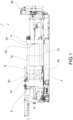
- a die-casting machine with toggle-joint comprises a base 2 which extends longitudinally, a first fixed vertical surface 4, a second fixed vertical surface 6 longitudinally spaced apart from the first fixed surface 4, and a vertical movable surface 8, placed between the fixed surfaces 4, 6 and movable horizontally on command.
- the position of said second fixed surface is adjustable as a function of the height of the mold.
- the two fixed surfaces 4, 6 are rigidly joined by horizontal columns 10, generally in a single piece of steel, which extend longitudinally; the movable surface 8 is guided on the base 2 and supported slidingly by the horizontal columns 10 to perform a longitudinal movement from and towards the first fixed surface 4.
- An internal face 4a of the first fixed surface 4 carries a first half-mold (or half-fixed mold); an inner face 8a of the movable surface 8, facing the inner face 4a of the first fixed surface 4, carries a movable half-mold.
- the two half-molds consist of complementary parts which, when coupled together, form a mold impression, corresponding to the shape of the piece to be obtained by die-casting.
- the machine 1 further comprises an injection unit 20 for delivering molten metal into the mold cavity when this is closed.
- the machine 1 further comprises at least one hydraulic cylinder 30, for example arranged so as to cross the second fixed surface 6, connected to the movable surface 8 to move it longitudinally, and a toggle-joint system 40, for example arranged between the second fixed surface 6 and the movable surface 8, for locking the movable plane 8 in the position of engagement with the first fixed surface 4, in which the mold is closed.
- Each horizontal column 10 extends longitudinally along a respective column axis X between a first end 10', fixed to the first fixed surface 4, and a second end 10", fixed to the second fixed surface 6.
- the horizontal column 10 has a respective threaded section 12 comprising a thread 14 characterized by a predefined pitch P and a depth H.
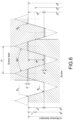
- the fundamental dimensions of the thread, and in particular the depth H, are defined as a function of the pitch P, for example, in the case of a triangular metric thread, by the ISO 261 standard, "General purpose metric screw threads - General plan” ( Figure 5 ) or, in the case of trapezoidal threading, by the UNI ISO 2901 ⁇ 2904 standard ( Figure 6 ).
- the thread 14 of the columns 10 takes up the correspondence between pitch P and depth H from the standard, but has variations in the profile, for example in the shape of the bottom of the groove.
- the thread 14 of the horizontal column 10 is obtained by means of a turning process which leads to the creation of a preliminary profile and a subsequent rolling process carried out on the preliminary profile, which leads to the creation of a final profile.
- a turning operation is carried out on a section to be threaded 42, i.e. a mechanical chip removal processing, which leads to the creation of a preliminary profile 44 having a stock 45 with respect to a final profile 46 which is to be obtained, at least at the grooves of the thread ( Figure 4b ).
- the stock preferably has a thickness of 0.5 - 4 millimeters, preferably of 1.8 - 3.5 millimeters, more preferably of 2 - 3 millimeters.
- a rolling process is carried out on the preliminary profile, or at least on a portion thereof corresponding to the grooves of the thread, i.e. a mechanical processing by plastic deformation, hot or cold (i.e. with heating or not of the product to be processed), which leads to the creation of the final profile 46 ( Figure 4c ), by virtue of the plastic deformation of the stock.
- the rolling carried out on a stock having the above dimensions allows a work hardening of the material to be obtained, and therefore greater resistance to fatigue, and at the same time allows the thread to be brought to the nominal dimensions.
- a finishing rolling is carried out on a stock of a few tenths of a millimeter only on a part of the thread, the remaining part already substantially having the nominal dimensions, and without carrying out any work hardening of the material.
- the rolling processing is carried out by means of rollers 50', 50", 50", typically opposite or arranged with the rotation axes placed at the vertices of an equilateral triangle ( Figure 4d ).
- this method allows very reliable threads to be obtained, since the bottom of the grooves, obtained by plastic deformation of the stock left by the turning process, has a residual compressive stress state which considerably increases the fatigue resistance of the components.
- the rolling is carried out both on the sides and on the grooves of the thread, to bring all the thread to the nominal size.
- a finishing rolling is carried out only on the bottom of the groove, on a stock of a few tenths of a millimeter.
- this method allows operating by rolling to obtain the final profile even when the thread pitch, and therefore the depth of the grooves, is considerable, for example equal to or greater than 10 millimeters, since the first turning process allows part of the material to be removed and to then operate by rolling only on the stock. Otherwise, it would be technologically impossible to operate by rolling directly on the initial semi-finished cylinder, due to the very high actions required to obtain the plastic deformation.
- the Applicant has found that it is possible to operate by complete rolling (i.e., without preliminary turning) only to obtain threads with a maximum depth of 5 or 6 millimeters; in the case of greater depths, the necessary forces that come into play are so high that they make complete rolling processing impractical.
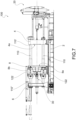
- a die-casting machine without toggle-joint 100 has structural and functional features similar to those of the machine with toggle-joint described above, but comprises locking jaws 122 for locking the movable plane 8 in the engagement position with the first fixed surface 4, in which the mold is closed.
- the locking jaws 122 are supported by the movable surface 8, and in particular applied to an external face 8b of the movable surface 8; moreover, said locking jaws 122 are preferably operated by means of actuators, for example hydraulic ones.
- each horizontal column 110 extends longitudinally along a respective column axis X between a first end 110', fixed to the first fixed surface 4, and a second end 110", supported by the second fixed surface 6.
- the horizontal column 110 has a threaded section 112, preferably made according to what is described above for the threaded section 12 of the horizontal columns 10.
- each horizontal column 110 has, in an intermediate position between the first end 110' and the second end 110", a shaped section 114 on which the locking jaws 122 are forcibly tightened to close the mold by means of a radial locking.
- Each shaped section 114 comprises a plurality of raised circumferential ribs 116 longitudinally spaced so as to form respective circumferential grooves 118.
- the shaped section 114 i.e. the ribs 116 and the grooves 118, is obtained by means of a turning process which leads to the creation of a preliminary profile and a subsequent rolling process carried out on the preliminary profile, which leads to the creation of a final profile, as described above for the thread 14.
- this method of manufacturing the shaped section 114 allows particularly reliable horizontal columns to be obtained, since the bottom of the grooves has residual compression stress state due to rolling.
Landscapes
- Engineering & Computer Science (AREA)
- Mechanical Engineering (AREA)
- Manufacturing & Machinery (AREA)
- Life Sciences & Earth Sciences (AREA)
- Agronomy & Crop Science (AREA)
- Moulds For Moulding Plastics Or The Like (AREA)
- Forging (AREA)
- Molds, Cores, And Manufacturing Methods Thereof (AREA)
Claims (10)
- Verfahren zum Herstellen einer horizontalen Säule (10) einer Druckgussmaschine (1) mit Kniehebelgelenk aus einem halbfertigen Zylinder (40), wobei die horizontale Säule (10) zumindest einen Gewindebereich (12) aufweist, der ein Gewinde (14) zur Verbindung mit einer festen Fläche bzw. Oberfläche (4, 6) der Maschine umfasst, umfassend die Schritte eines Durchführens, an dem halbfertigen Zylinder (40), einer Drehung bzw. Drehbearbeitung, die zur Erzeugung eines vorläufigen Profils von zumindest einem Abschnitt des Gewindes (14) führt, und eines anschließenden Durchführens, an dem vorläufigen Profil, eines Walzens bzw. einer Walzbearbeitung, um ein endgültiges Profil (46) des Abschnitts des Gewindes (14) und eine Kaltverfestigung bzw. -umformung des Materials zu erhalten, wobei das Drehen zur Erzeugung des vorläufigen Profils (44) führt, das zumindest an Rillen des Gewindes (14) einen unbearbeiteten Werkstoff bzw. Rohling bzw. Vorformling (45) in Bezug auf das endgültige Profil (46) aufweist, wobei der Vorformling (45) eine Dicke von 0,5 - 4 Millimetern, vorzugsweise von 1,8 - 3,5 Millimetern, noch bevorzugter von 2 - 3 Millimeter aufweist.
- Verfahren nach Anspruch 1, wobei das Gewinde der Säule eine Steigung bzw. Ganghöhe größer oder gleich 14 Millimeter (p≥14 Millimeter) aufweist.
- Verfahren nach Anspruch 1 oder 2, wobei das Walzen an Seiten und Rillen des vorläufigen Profils durchgeführt wird.
- Druckgussmaschine (1) mit Kniehebelgelenk, umfassend zumindest eine horizontale Säule (10), die nach einem der vorhergehenden Ansprüche hergestellt ist.
- Maschine nach Anspruch 4, wobei die horizontale Säule (10) einen Gewindebereich (12) mit einer Tiefe (H) des Gewindes (14) aufweist, die größer oder gleich 6 Millimeter ist, wobei zumindest der Boden der Rillen des Gewindebereichs einen Restdruck- bzw. -kompressionsspannungszustand aufweist.
- Verfahren zum Herstellen einer horizontalen Säule (110) einer Druckgussmaschine (100) ohne Kniehebelgelenk aus einem halbfertigen Zylinder (40), wobei die horizontale Säule (110) zumindest einen geformten Bereich (114) für den Eingriff mit Verriegelungsklauen (122) der Maschine (100) aufweist, der mit einer Mehrzahl von erhöhten Umfangsrippen (116) versehen ist, die longitudinal bzw. in Längsrichtung beabstandet sind, um jeweilige Umfangsrillen (118) zu bilden, umfassend die Schritte eines Durchführens, an dem halbfertigen Zylinder (40), einer Drehung bzw. Drehbearbeitung, die zur Erzeugung eines vorläufigen Profils von zumindest einem Abschnitt des geformten Bereichs (114) führt, und eines anschließenden Durchführens, an dem vorläufigen Profil, eines Walzens bzw. einer Walzbearbeitung, um ein endgültiges Profil (46) des Abschnitts des geformten Bereichs (114) und eine Kaltverfestigung bzw. -umformung des Materials zu erhalten, wobei das Drehen zur Erzeugung des vorläufigen Profils (44) führt, das zumindest an den Rillen (118) einen unbearbeiteten Werkstoff bzw. Rohling bzw. Vorformling (45) in Bezug auf das endgültige Profil (46) aufweist, wobei der Vorformling (45) eine Dicke von 0,5 - 4 Millimetern, vorzugsweise von 1,8 - 3,5 Millimetern, noch bevorzugter von 2 - 3 Millimetern aufweist.
- Verfahren nach Anspruch 6, wobei die Rippen der Säule eine Steigung bzw. Ganghöhe größer oder gleich 14 Millimeter (p≥14 Millimeter) aufweisen.
- Verfahren nach Anspruch 6 oder 7, wobei das Walzen an Seiten und Rillen des vorläufigen Profils durchgeführt wird.
- Druckgussmaschine (100) ohne Kniehebelgelenk, umfassend zumindest eine horizontale Säule (110), die nach einem der Ansprüche 6 bis 8 hergestellt ist.
- Maschine nach Anspruch 9, wobei die horizontale Säule (110) einen geformten Bereich (114) mit Rillen (118) mit einer Tiefe (H) umfasst, die größer oder gleich 6 Millimeter ist, wobei zumindest der Boden der Rillen einen Restdruck- bzw. - kompressionsspannungszustand aufweist.
Priority Applications (1)
| Application Number | Priority Date | Filing Date | Title |
|---|---|---|---|
| RS20250563A RS66879B1 (sr) | 2021-03-09 | 2022-03-09 | Postupak za proizvodnju mašine za livenje i mašina za livenje |
Applications Claiming Priority (2)
| Application Number | Priority Date | Filing Date | Title |
|---|---|---|---|
| IT102021000005498A IT202100005498A1 (it) | 2021-03-09 | 2021-03-09 | Metodo di realizzazione di una macchina per pressofusione e macchina per pressofusione |
| PCT/IB2022/052090 WO2022189991A1 (en) | 2021-03-09 | 2022-03-09 | Method for manufacturing a die-casting machine and die- casting machine |
Publications (3)
| Publication Number | Publication Date |
|---|---|
| EP4304794A1 EP4304794A1 (de) | 2024-01-17 |
| EP4304794B1 true EP4304794B1 (de) | 2025-04-02 |
| EP4304794C0 EP4304794C0 (de) | 2025-04-02 |
Family
ID=76034970
Family Applications (1)
| Application Number | Title | Priority Date | Filing Date |
|---|---|---|---|
| EP22721459.0A Active EP4304794B1 (de) | 2021-03-09 | 2022-03-09 | Verfahren zur herstellung einer druckgiessmaschine und druckgiessmaschine |
Country Status (7)
| Country | Link |
|---|---|
| US (1) | US12479023B2 (de) |
| EP (1) | EP4304794B1 (de) |
| JP (1) | JP2024510208A (de) |
| CN (1) | CN117460592A (de) |
| IT (1) | IT202100005498A1 (de) |
| RS (1) | RS66879B1 (de) |
| WO (1) | WO2022189991A1 (de) |
Families Citing this family (1)
| Publication number | Priority date | Publication date | Assignee | Title |
|---|---|---|---|---|
| WO2026022538A1 (en) | 2024-07-24 | 2026-01-29 | Italpressegauss S.P.A. Societa' Unipersonale | Horizontal column of a die-casting machine, die-casting machine and manufacturing method |
Family Cites Families (10)
| Publication number | Priority date | Publication date | Assignee | Title |
|---|---|---|---|---|
| CH576829A5 (de) * | 1975-02-11 | 1976-06-30 | Buehler Ag Geb | |
| DE3866209D1 (de) * | 1987-09-11 | 1991-12-19 | Mitsubishi Heavy Ind Ltd | Druckguss-formschliessvorrichtung. |
| US5066217A (en) * | 1990-08-08 | 1991-11-19 | Ube Industries, Ltd. | Clamping apparatus for an injection molding machine |
| JPH052913U (ja) * | 1991-06-28 | 1993-01-19 | 宇部興産株式会社 | 成形機の型締装置 |
| JP3524622B2 (ja) * | 1995-03-28 | 2004-05-10 | 三菱重工業株式会社 | 半割ナット装置 |
| JPH10315051A (ja) * | 1997-05-16 | 1998-12-02 | Japan Steel Works Ltd:The | タイバーのネジの疲労強度の改善方法及びローラバニシング装置 |
| JP4372530B2 (ja) * | 2003-12-17 | 2009-11-25 | 東洋機械金属株式会社 | 型締装置 |
| JP2006321181A (ja) * | 2005-05-20 | 2006-11-30 | Ube Machinery Corporation Ltd | 射出成形機の型締装置 |
| DE102006027611A1 (de) * | 2006-06-13 | 2007-12-20 | EMUGE-Werk Richard Glimpel GmbH & Co. KG Fabrik für Präzisionswerkzeuge | Verfahren und Werkzeug oder Werkzeugsatz zur Erzeugung eines Gewindes in wenigstens zwei Arbeitsschritten |
| WO2012090734A1 (ja) * | 2010-12-28 | 2012-07-05 | 宇部興産機械株式会社 | 型締装置及び成形品押出方法 |
-
2021
- 2021-03-09 IT IT102021000005498A patent/IT202100005498A1/it unknown
-
2022
- 2022-03-09 RS RS20250563A patent/RS66879B1/sr unknown
- 2022-03-09 CN CN202280020296.6A patent/CN117460592A/zh active Pending
- 2022-03-09 JP JP2023555535A patent/JP2024510208A/ja active Pending
- 2022-03-09 WO PCT/IB2022/052090 patent/WO2022189991A1/en not_active Ceased
- 2022-03-09 US US18/549,092 patent/US12479023B2/en active Active
- 2022-03-09 EP EP22721459.0A patent/EP4304794B1/de active Active
Also Published As
| Publication number | Publication date |
|---|---|
| WO2022189991A1 (en) | 2022-09-15 |
| RS66879B1 (sr) | 2025-07-31 |
| US20240149335A1 (en) | 2024-05-09 |
| CN117460592A (zh) | 2024-01-26 |
| JP2024510208A (ja) | 2024-03-06 |
| US12479023B2 (en) | 2025-11-25 |
| IT202100005498A1 (it) | 2022-09-09 |
| EP4304794C0 (de) | 2025-04-02 |
| EP4304794A1 (de) | 2024-01-17 |
Similar Documents
| Publication | Publication Date | Title |
|---|---|---|
| US20090113977A1 (en) | Method and apparatus for forming of panels and similar parts | |
| KR100397266B1 (ko) | 난가공재의 결정립 미세화장치 및 방법 | |
| EP4304794B1 (de) | Verfahren zur herstellung einer druckgiessmaschine und druckgiessmaschine | |
| WO2008069269A1 (ja) | エルボ素材およびその製造装置ならびに製造方法 | |
| CN1166469C (zh) | 带整体支承裙座的厚壁封头的制造方法 | |
| JPH0366983B2 (de) | ||
| US6688154B2 (en) | Die for forging rotor, forge production system and forging method using the die, and rotor | |
| CN119748068B (zh) | 一种模具的公头镶嵌工艺 | |
| CN102366883A (zh) | 一种钛合金(tc4)喷管座壳体的模锻工艺 | |
| US12090544B2 (en) | Rebar upsetting process and rebar upset forging machine | |
| CN111922266A (zh) | 热锻螺栓加工方法 | |
| KR20210080738A (ko) | 인코넬강의 볼트 제조방법 | |
| CN217142174U (zh) | 钢筋镦粗机 | |
| US20100126641A1 (en) | Method of Producing Bicycle Ratchet Bushing | |
| US9566641B2 (en) | Forging apparatus | |
| KR100455072B1 (ko) | 타이로드 엔드 냉간 가공방법 | |
| CN205289622U (zh) | 花键轴叉平锻镶模 | |
| US10974429B2 (en) | Pull or push rod or a locking nut for a molding machine | |
| US10967549B2 (en) | Pull or push rod or locking nut for a molding machine | |
| KR101286304B1 (ko) | 티볼트의 시트 제조방법 | |
| CN205289623U (zh) | 花键轴叉平锻模具 | |
| KR101638101B1 (ko) | 피드롤 하우징의 보수 방법 및 보수장치 | |
| KR20230111003A (ko) | 열처리가 필요없는 비조질강 소재의 장볼트 헤드 단조성형용 금형 | |
| KR20100001338A (ko) | 커넥팅 로드의 제조 방법 | |
| CN205289621U (zh) | 中型花键轴叉锻造模架 |
Legal Events
| Date | Code | Title | Description |
|---|---|---|---|
| STAA | Information on the status of an ep patent application or granted ep patent |
Free format text: STATUS: UNKNOWN |
|
| STAA | Information on the status of an ep patent application or granted ep patent |
Free format text: STATUS: THE INTERNATIONAL PUBLICATION HAS BEEN MADE |
|
| PUAI | Public reference made under article 153(3) epc to a published international application that has entered the european phase |
Free format text: ORIGINAL CODE: 0009012 |
|
| STAA | Information on the status of an ep patent application or granted ep patent |
Free format text: STATUS: REQUEST FOR EXAMINATION WAS MADE |
|
| 17P | Request for examination filed |
Effective date: 20230901 |
|
| AK | Designated contracting states |
Kind code of ref document: A1 Designated state(s): AL AT BE BG CH CY CZ DE DK EE ES FI FR GB GR HR HU IE IS IT LI LT LU LV MC MK MT NL NO PL PT RO RS SE SI SK SM TR |
|
| DAV | Request for validation of the european patent (deleted) | ||
| DAX | Request for extension of the european patent (deleted) | ||
| REG | Reference to a national code |
Ref country code: DE Ref legal event code: R079 Free format text: PREVIOUS MAIN CLASS: B22D0017220000 Ipc: B23P0015000000 Ref document number: 602022012611 Country of ref document: DE |
|
| RIC1 | Information provided on ipc code assigned before grant |
Ipc: B29C 45/67 20060101ALI20241028BHEP Ipc: B29C 45/17 20060101ALI20241028BHEP Ipc: B21H 7/18 20060101ALI20241028BHEP Ipc: B22D 17/22 20060101ALI20241028BHEP Ipc: B22D 17/26 20060101ALI20241028BHEP Ipc: B23G 1/02 20060101ALI20241028BHEP Ipc: B23P 9/02 20060101ALI20241028BHEP Ipc: B23P 15/00 20060101AFI20241028BHEP Ipc: B21H 3/04 20060101ALI20241028BHEP |
|
| GRAP | Despatch of communication of intention to grant a patent |
Free format text: ORIGINAL CODE: EPIDOSNIGR1 |
|
| STAA | Information on the status of an ep patent application or granted ep patent |
Free format text: STATUS: GRANT OF PATENT IS INTENDED |
|
| INTG | Intention to grant announced |
Effective date: 20241205 |
|
| GRAS | Grant fee paid |
Free format text: ORIGINAL CODE: EPIDOSNIGR3 |
|
| GRAA | (expected) grant |
Free format text: ORIGINAL CODE: 0009210 |
|
| STAA | Information on the status of an ep patent application or granted ep patent |
Free format text: STATUS: THE PATENT HAS BEEN GRANTED |
|
| AK | Designated contracting states |
Kind code of ref document: B1 Designated state(s): AL AT BE BG CH CY CZ DE DK EE ES FI FR GB GR HR HU IE IS IT LI LT LU LV MC MK MT NL NO PL PT RO RS SE SI SK SM TR |
|
| REG | Reference to a national code |
Ref country code: GB Ref legal event code: FG4D |
|
| REG | Reference to a national code |
Ref country code: CH Ref legal event code: EP |
|
| REG | Reference to a national code |
Ref country code: IE Ref legal event code: FG4D |
|
| REG | Reference to a national code |
Ref country code: DE Ref legal event code: R096 Ref document number: 602022012611 Country of ref document: DE |
|
| U01 | Request for unitary effect filed |
Effective date: 20250423 |
|
| U07 | Unitary effect registered |
Designated state(s): AT BE BG DE DK EE FI FR IT LT LU LV MT NL PT RO SE SI Effective date: 20250430 |
|
| PG25 | Lapsed in a contracting state [announced via postgrant information from national office to epo] |
Ref country code: ES Free format text: LAPSE BECAUSE OF FAILURE TO SUBMIT A TRANSLATION OF THE DESCRIPTION OR TO PAY THE FEE WITHIN THE PRESCRIBED TIME-LIMIT Effective date: 20250402 |
|
| PG25 | Lapsed in a contracting state [announced via postgrant information from national office to epo] |
Ref country code: GR Free format text: LAPSE BECAUSE OF FAILURE TO SUBMIT A TRANSLATION OF THE DESCRIPTION OR TO PAY THE FEE WITHIN THE PRESCRIBED TIME-LIMIT Effective date: 20250703 Ref country code: NO Free format text: LAPSE BECAUSE OF FAILURE TO SUBMIT A TRANSLATION OF THE DESCRIPTION OR TO PAY THE FEE WITHIN THE PRESCRIBED TIME-LIMIT Effective date: 20250702 |
|
| PG25 | Lapsed in a contracting state [announced via postgrant information from national office to epo] |
Ref country code: PL Free format text: LAPSE BECAUSE OF FAILURE TO SUBMIT A TRANSLATION OF THE DESCRIPTION OR TO PAY THE FEE WITHIN THE PRESCRIBED TIME-LIMIT Effective date: 20250402 |
|
| PG25 | Lapsed in a contracting state [announced via postgrant information from national office to epo] |
Ref country code: HR Free format text: LAPSE BECAUSE OF FAILURE TO SUBMIT A TRANSLATION OF THE DESCRIPTION OR TO PAY THE FEE WITHIN THE PRESCRIBED TIME-LIMIT Effective date: 20250402 |
|
| PG25 | Lapsed in a contracting state [announced via postgrant information from national office to epo] |
Ref country code: IS Free format text: LAPSE BECAUSE OF FAILURE TO SUBMIT A TRANSLATION OF THE DESCRIPTION OR TO PAY THE FEE WITHIN THE PRESCRIBED TIME-LIMIT Effective date: 20250802 |
|
| PG25 | Lapsed in a contracting state [announced via postgrant information from national office to epo] |
Ref country code: SM Free format text: LAPSE BECAUSE OF FAILURE TO SUBMIT A TRANSLATION OF THE DESCRIPTION OR TO PAY THE FEE WITHIN THE PRESCRIBED TIME-LIMIT Effective date: 20250402 |
|
| PG25 | Lapsed in a contracting state [announced via postgrant information from national office to epo] |
Ref country code: CZ Free format text: LAPSE BECAUSE OF FAILURE TO SUBMIT A TRANSLATION OF THE DESCRIPTION OR TO PAY THE FEE WITHIN THE PRESCRIBED TIME-LIMIT Effective date: 20250402 |
|
| PG25 | Lapsed in a contracting state [announced via postgrant information from national office to epo] |
Ref country code: SK Free format text: LAPSE BECAUSE OF FAILURE TO SUBMIT A TRANSLATION OF THE DESCRIPTION OR TO PAY THE FEE WITHIN THE PRESCRIBED TIME-LIMIT Effective date: 20250402 |
|
| PLBE | No opposition filed within time limit |
Free format text: ORIGINAL CODE: 0009261 |
|
| STAA | Information on the status of an ep patent application or granted ep patent |
Free format text: STATUS: NO OPPOSITION FILED WITHIN TIME LIMIT |
|
| REG | Reference to a national code |
Ref country code: CH Ref legal event code: L10 Free format text: ST27 STATUS EVENT CODE: U-0-0-L10-L00 (AS PROVIDED BY THE NATIONAL OFFICE) Effective date: 20260211 |