EP4304503B1 - Osteosyntheseplatte als ersatz einer synarthrose in form einer symphyse - Google Patents
Osteosyntheseplatte als ersatz einer synarthrose in form einer symphyse Download PDFInfo
- Publication number
- EP4304503B1 EP4304503B1 EP22710560.8A EP22710560A EP4304503B1 EP 4304503 B1 EP4304503 B1 EP 4304503B1 EP 22710560 A EP22710560 A EP 22710560A EP 4304503 B1 EP4304503 B1 EP 4304503B1
- Authority
- EP
- European Patent Office
- Prior art keywords
- plate
- segment
- fixation
- connecting segment
- osteosynthesis
- Prior art date
- Legal status (The legal status is an assumption and is not a legal conclusion. Google has not performed a legal analysis and makes no representation as to the accuracy of the status listed.)
- Active
Links
Images

Classifications
-
- A—HUMAN NECESSITIES
- A61—MEDICAL OR VETERINARY SCIENCE; HYGIENE
- A61B—DIAGNOSIS; SURGERY; IDENTIFICATION
- A61B17/00—Surgical instruments, devices or methods
- A61B17/56—Surgical instruments or methods for treatment of bones or joints; Devices specially adapted therefor
- A61B17/58—Surgical instruments or methods for treatment of bones or joints; Devices specially adapted therefor for osteosynthesis, e.g. bone plates, screws or setting implements
- A61B17/68—Internal fixation devices, including fasteners and spinal fixators, even if a part thereof projects from the skin
- A61B17/80—Cortical plates, i.e. bone plates; Instruments for holding or positioning cortical plates, or for compressing bones attached to cortical plates
- A61B17/8061—Cortical plates, i.e. bone plates; Instruments for holding or positioning cortical plates, or for compressing bones attached to cortical plates specially adapted for particular bones
- A61B17/8066—Cortical plates, i.e. bone plates; Instruments for holding or positioning cortical plates, or for compressing bones attached to cortical plates specially adapted for particular bones for pelvic reconstruction
-
- A—HUMAN NECESSITIES
- A61—MEDICAL OR VETERINARY SCIENCE; HYGIENE
- A61B—DIAGNOSIS; SURGERY; IDENTIFICATION
- A61B17/00—Surgical instruments, devices or methods
- A61B17/56—Surgical instruments or methods for treatment of bones or joints; Devices specially adapted therefor
- A61B17/58—Surgical instruments or methods for treatment of bones or joints; Devices specially adapted therefor for osteosynthesis, e.g. bone plates, screws or setting implements
- A61B17/68—Internal fixation devices, including fasteners and spinal fixators, even if a part thereof projects from the skin
- A61B17/80—Cortical plates, i.e. bone plates; Instruments for holding or positioning cortical plates, or for compressing bones attached to cortical plates
- A61B17/8052—Cortical plates, i.e. bone plates; Instruments for holding or positioning cortical plates, or for compressing bones attached to cortical plates immobilised relative to screws by interlocking form of the heads and plate holes, e.g. conical or threaded
-
- A—HUMAN NECESSITIES
- A61—MEDICAL OR VETERINARY SCIENCE; HYGIENE
- A61F—FILTERS IMPLANTABLE INTO BLOOD VESSELS; PROSTHESES; DEVICES PROVIDING PATENCY TO, OR PREVENTING COLLAPSING OF, TUBULAR STRUCTURES OF THE BODY, e.g. STENTS; ORTHOPAEDIC, NURSING OR CONTRACEPTIVE DEVICES; FOMENTATION; TREATMENT OR PROTECTION OF EYES OR EARS; BANDAGES, DRESSINGS OR ABSORBENT PADS; FIRST-AID KITS
- A61F2/00—Filters implantable into blood vessels; Prostheses, i.e. artificial substitutes or replacements for parts of the body; Appliances for connecting them with the body; Devices providing patency to, or preventing collapsing of, tubular structures of the body, e.g. stents
- A61F2/02—Prostheses implantable into the body
- A61F2/30—Joints
- A61F2/30767—Special external or bone-contacting surface, e.g. coating for improving bone ingrowth
- A61F2/30771—Special external or bone-contacting surface, e.g. coating for improving bone ingrowth applied in original prostheses, e.g. holes or grooves
-
- A—HUMAN NECESSITIES
- A61—MEDICAL OR VETERINARY SCIENCE; HYGIENE
- A61F—FILTERS IMPLANTABLE INTO BLOOD VESSELS; PROSTHESES; DEVICES PROVIDING PATENCY TO, OR PREVENTING COLLAPSING OF, TUBULAR STRUCTURES OF THE BODY, e.g. STENTS; ORTHOPAEDIC, NURSING OR CONTRACEPTIVE DEVICES; FOMENTATION; TREATMENT OR PROTECTION OF EYES OR EARS; BANDAGES, DRESSINGS OR ABSORBENT PADS; FIRST-AID KITS
- A61F2/00—Filters implantable into blood vessels; Prostheses, i.e. artificial substitutes or replacements for parts of the body; Appliances for connecting them with the body; Devices providing patency to, or preventing collapsing of, tubular structures of the body, e.g. stents
- A61F2/02—Prostheses implantable into the body
- A61F2/30—Joints
- A61F2/30767—Special external or bone-contacting surface, e.g. coating for improving bone ingrowth
- A61F2/30771—Special external or bone-contacting surface, e.g. coating for improving bone ingrowth applied in original prostheses, e.g. holes or grooves
- A61F2002/30772—Apertures or holes, e.g. of circular cross section
- A61F2002/30784—Plurality of holes
Definitions
- the present invention relates to an osteosynthesis plate according to the preamble of claim 1.
- Osteosynthesis plates suitable for replacing synarthrosis are typically strip-shaped or L-angled flat metal bars.
- the problem is that a pelvis or other body parts are subject to constant movement. During movement, corresponding tensile and compressive forces act in the plane of the metal bar, which are transferred to the screws. This causes the bone screw to constantly move back and forth, expanding the drill hole within the bone. This can lead to the screw becoming loose from its anchorage in the bone, or to a screw or plate fracture.
- the DE 26 03 087 B1 discloses a generic osteosynthesis plate with fixation plate segments for stabilizing a symphysis, each having a support surface for resting on a pelvic rim and a protruding connecting segment that protrudes from the fixation plate segments in such a way that it is suitable for extending along the inner side of a person's pelvis.
- the material of the osteosymphysis plate is thermoplastic and softens when heated, adapting to the anatomy of the symphysis.
- the DE 102012 010 024 A1 discloses an implant carrier, which, however, does not correspond to the generic design of the preamble of the present invention.
- the aim of the features of the preamble is to define an object with which a special force deflection into the implant is associated with a movement.
- the introduced movement-related force is, in this case, different from the DE 26 03 087 B1 not perpendicular to the fixation plate into the connecting segment. Rather, the DE 10 2012 010 024 A1 Through the direct and shortest connection of two fixation plates, tensile forces are exerted on these very fixation plates, resulting in lateral loading of the connecting elements (bone screws, etc.).
- the disclosed construct consists of at least 13 parts that are assembled and allow lateral displacement of the two bone plates by means of a crossbar titanium rod.
- the movement occurs only in one plane – the lateral plane and the extent of the movement are defined by the length of the slot in the crossbar ( Fig. 1 , no. 20). The traverse slides without resistance.
- the plate is designed to stabilize acetabular fractures (fractures of the hip socket)—that is, fractures in the pelvic region—located 10 cm from the symphysis pubis.
- This plate features an additional surface in the center of the plate specifically designed to support the acetabular fracture. This surface supports the quadrilateral lamina and prevents protrusion/medialization of the femoral head.
- the construct pursues a different goal in terms of structure, design, and purpose than the present invention.
- FIG. 14a and 14b show two plates connected by a U-shaped metal plate. The purpose of this connection is to bypass nerves and thus prevent them from becoming trapped under the plate. It is also possible to bend the U-shaped part, thus better adapting the plate to the geometry of the jaw, as can be seen from paragraphs [0066] and [0067]. The bend is thus "in plane,” i.e., along the plane of the support surfaces of the fixation elements, and therefore cannot cushion or stabilize any axial displacement of the pelvic bones against each other.
- the osteosynthesis plate of this category is DE 26 03 087 B1 It is broadly formed and encloses or encompasses the pelvic rim and the inner surface of the pelvis like a cuff.
- the surface of the plate is specifically designed to maximize its size to achieve high rigidity. Screws are also inserted close to the symphysis pubis to ensure maximum plate stability.
- the plate lies on the outer surface of the pelvis—that is, between the skin and bone.
- the fixation plates are rigidly fixed. This is problematic in that the connected pelvic bones themselves move against each other as a result of movement, so that rigid fixation can lead to a gradual loosening of the connection points between the osteosynthesis plate and the pelvic bone.
- the object of the present invention is to provide an osteosynthesis plate which allows a force deflection
- the present invention solves the above-mentioned problem by an osteosynthesis plate having the features of claim 1.
- a basic idea of the present invention is to design an osteosynthesis plate that is not rigid, but rather springy and at the same time ergonomic.
- the degree of springiness is known to those skilled in the art as spring hardness and is usually specified using a so-called spring constant.
- the spring constant is a value assigned to a spring.
- the spring constant is used to design and calculate the spring for the desired purpose.
- the spring constant is a complex physical quantity and can be influenced by various factors of the spring. It is calculated from the deflection of the spring and the necessary and resulting force. (See, among others, https://www.maschinenbau-sammlung.de/skript3/mechanik/kinetik/114-federkonstante).
- An osteosynthesis plate according to the invention should be suitable for replacing synarthrosis.
- the osteosynthesis plate has two fixation plate segments for securing the osteosynthesis plate to two bones of a pelvis.
- Each of the fixation plate segments defines a support surface. This can be flat, curved, or individually adapted to the patient. Specifically in the case of symphysis replacement in the pelvic region, the support surface serves to rest on the pelvic brim of a pelvic bone, while the connecting element protrudes from the fixation plate segments in such a way that it extends at least partially along the inner surface of the pelvis or over a portion of the inner surface of the pelvis, and particularly preferably rests against it.
- each support surface regardless of its shape, has at least one normal vector which is perpendicular to the support surface.
- the osteosynthesis plate also features a connecting segment that connects the two fixation plate segments and protrudes from the fixation plate segments. While the fixation plate segments define a connection plane in continuation of their extension to a theoretical connection of the fixation plate segments at the shortest distance, the connecting segment preferably lies outside this connection plane.
- the connecting segment can be arranged at the edge of the fixation plate segment and be angled, in particular bent, at an angle of more than 45° relative to a fictitious extension of the support surface.
- This angled bending refers to an orientation relative to an in-plane (alignment in the plane of the support surface) or a bend relative to the aforementioned fictitious extension. It is to be understood as an indication of an absolute value and can therefore also represent a negative value for an angle specification in the strictly mathematical sense.
- the connecting segment can advantageously deviate by less than 45° from the normal vector, Due to its elasticity, the osteosynthesis plate according to the invention can advantageously distribute the force acting on the connection point to the bone over a longer period of time, thereby dampening the load on the connection point.
- a mechanical interface can be attached to the edge as part of the connecting segment which is designed as an arc or bend.
- the connecting segment extends at the aforementioned angle.
- the mechanical interface occupies less than 10%, preferably less than 5%, of the total length of the mechanical connecting segment.
- the mechanical interface can preferably be a weld or a bend.
- the connecting segment runs at an angle of less than 45° relative to the normal vector. This means that there may also be subsections of the connecting segment that form an angle of more than 45° relative to the connecting segment. However, this is preferably only a small portion of the connecting segment, as previously defined.
- the connecting segment is designed as a spring element.
- the connecting segment is configured such that a freely swinging fixation plate segment of the osteosynthesis plate, when fixed on one side, is deflected relative to the second fixation plate segment by a distance ⁇ s of at least 1.5 mm, preferably 1.8 to 5.0 mm, when a force of 350 N is applied from a direction parallel to the normal vector.
- the deflection and the previous definition replace the specification of a spring constant to characterize the connecting segment as a spring element.
- the force reduction causes the forces acting on the bone screws to be reduced.
- the connecting segment can advantageously be designed as a flat connecting segment with an average plate thickness that is at least 1.5 times smaller, preferably 2-5 times smaller, than the average width of the flat segment. This design ensures particular mechanical stability of the connection.
- the length of the connecting segment can be at least twice as long as the shortest distance between the edges of the two fixation plate segments in order to achieve a high degree of flexibility for compensatory deformation of the osteosynthesis plate.
- the length of the connecting segment is at least five times the average width of the connecting segment.
- the connecting segment protrudes by more than 45°, preferably between 85 and 95°, relative to the fixation plate segment. Particularly preferably, this can be a bend relative to the fixation plate segment with a corresponding bending range.
- the fixation plates can have at least two, preferably three drill holes for each of which a mechanical connecting means, in particular a bone screw, can be inserted.
- the osteosynthesis plate is preferably formed in one piece to enable optimal force redirection through the material.
- the entire osteosynthesis plate is made of a ductile material, particularly preferably titanium and/or stainless steel and/or a metal alloy comprising titanium and/or iron.
- the osteosynthesis plate has a coating, particularly made of a resorbable material or containing an anti-inflammatory agent, at least in sections. This can be particularly useful in the area of the contact surfaces.
- fixation plate segments and the connecting segment have the same plate thickness. Minor deviations of 10% or less of the plate thickness are negligible. Furthermore, this does not create any additional mechanical weak points.
- fixation plate segments have a longitudinal extension and a transverse extension perpendicular to it, with the connecting segment being arranged at the edge and centrally with respect to the longitudinal extension. This ensures the transmission of force to all drill holes of the fixation plate segment are evenly distributed in the event of deformation.
- an interface between each fixation plate segment and the connecting segment is designed as a bend, preferably with a bending radius which is at least larger, particularly preferably at least twice as large, as the average plate thickness of the connecting segment, so that force deflection is optimized.
- the connecting segment can be curved and convex toward the fixation points of the fixation plate segments. This achieves even better force reduction.
- an osteosynthesis plate within the scope of the present invention is not to be understood as an exclusively flat object, but it can have one or more sub-segments, for example a bent connecting segment, which can protrude in particular at an angle from a plate plane, preferably also at more than 45°, in particular perpendicularly.
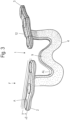
- the illustrated embodiment shows an osteosynthesis plate 1 for fixation of a pelvis, in particular due to a traumatic rupture of the symphysis.
- the osteosynthesis plate 1 comprises a first and a second fixation plate segment 2 and 3, as well as a flat connection segment 4, which is arranged between the two fixation plates 2, 3 and connects them to one another.
- the flat connection segment 4 has an average plate thickness Pd2 of preferably at least 2 mm, preferably between 2.5 and 5 mm, in particular 3 mm +/- 0.2 mm.
- the plate thickness Pd2 of the flat connection segment 4 is substantially uniform, i.e., over more than 90% of the length l1 of the flat connection segment 4.
- the flat connection segment 4 preferably has an average width b1 of preferably at least 5 mm, preferably between 7 and 15 mm, in particular 9 mm +/- 0.8 mm.
- the plate thickness Pd2 of the compartment connection segment 4 is substantially uniform, i.e., over more than 90% of the length l1 of the flat connection segment 4.
- the first and second fixation plates 2 and 3 each define a first and a second support surface 100 with a normal vector N.
- the two support surfaces 100 can be parallel to each other or lie on a common plane. However, the two support surfaces 100 can also be curved and/or arranged at an angle to each other.
- the flat connection segment 4 protrudes from the respective fixation plate 2 or 3 at an angle ⁇ of less than 45°, in particular at an angle of less than 5°, relative to the respective normal vector or the parallel vector.
- Fig. 1 the flat connection segment 4 protrudes from the drawing plane by this angle.
- the protrusion This occurs in such a way that a material segment arranged on the edge of the fixation plate segments, the flat connection segment, is bent relative to the fixation plate segments.
- the bend is also referred to below as the mechanical interface 12 and is a section of the flat connection segment 4.
- Each of the fixation plates 2 and 3 has at least one, preferably at least three, fixation points 5 for fixing the said fixation plate to a bone, in particular a pelvic bone.
- the fixation points 5 can be designed as drill holes through which fixation to the bone is achieved using corresponding screws 6, e.g., bone screws.
- the flat connection segment 4 is preferably designed such that it has a greater length l 1 than the shortest direct distance r between two closest-spaced fixation points 5 between the two fixation plate segments 2 and 3. In other words, the shortest distance r from a fixation point 5 of the first fixation plate 2 to a fixation point 5 of the second fixation plate 3 is determined. The length l 1 of the flat connection segment 4 is greater than this distance r.
- the osteosynthesis plate 1 is preferably formed in one piece and consists of a ductile material, preferably a metal, in particular titanium and/or stainless steel or an alloy with at least one of the two metals titanium and/or iron.
- the fixation plate segments 2, 3 in the variant of the Fig. 1-3 is designed as a three-hole plate, meaning it has three holes for the passage of bone screws 6 and for the fixation of the osteosynthesis plate to the two pelvic bones 13, which have been separated by a complete or incomplete rupture of the symphysis.
- the holes are arranged one behind the other in the longitudinal direction of the fixation plate segment 2 or 3.
- the holes correspond to the aforementioned fixation points 5.
- the holes can be selected to accommodate bone screws with a diameter of 2-5 mm, preferably 3-4 mm.
- the flat connection segment 4 extends from the edge of the fixation plate segment 2, 3 at the level of the central bore and is angled or bent at a substantially perpendicular angle from the fixation plate segment 2, 3.
- the flat connection segment 4 has a first region 6 with a first negative rise up to a first minimum 7, wherein the negative rise is directed away from the fixation plate segment.
- the flat connection segment 4 then has a second region 8 with a first positive slope, which extends to a first maximum 9.
- the length of this second region 8 is shorter, preferably more than 30% shorter, than the length of the first region.
- the positive slope is directed toward the fixation plate segment 2.
- the maximum 9 is thus spaced from the first and second fixation plate segments 2 and 3 and their connecting axis.
- the flat connection segment 4 then has a third region 10 with a second negative slope, which in turn extends to a second minimum 11.
- the first and third regions 6 and 7 are essentially the same length.
- the minima 7 and 11 are essentially at the same height when the osteosynthesis plate is in the relaxed state.
- the maximum 9 is arranged at the same distance from the two minima 7 and 11.
- the shape of the flat connection segment 4 corresponds to that of a "W.”
- the flat connection segment can also have the shape of a "U" in an alternative embodiment.
- the maximum width b 3 of the "W” preferably corresponds to at least 30 mm, particularly preferably between 35-60 mm, particularly preferably 45 mm +/- 5 mm.
- the maximum height h of the "W", or the length of the first region 6, measured from the surface on the fixation plate segment 2, is preferably at least 15 mm, preferably 20-45 mm, particularly preferably 30 mm +/- 3 mm.
- the width "W" of the flat connection segment 4 is greater than its height "H".
- the shape of the flat connection segment 4 is also convex, relative to the position of the fixation plate segments 2 and 3.
- the length l 2 of the fixation plate segment 2 is preferably between 25-45 mm, preferably 40 mm +/- 4 mm.
- the average width of the fixation plate segment b 2 over its entire length is preferably between 6-13 mm, preferably 10 mm +/- 1 mm.
- the distance r between the fixation plate segments 2, 3 from edge to edge is preferably less than the longitudinal extent of a fixation plate segment. It can preferably be between 6-10 mm, preferably 8 mm +/- 0.5 mm. However, the distance between the fixation plate segments 2, 3 can vary under deformation and the development of restoring forces. The aforementioned distance refers to an osteosynthesis plate in the unstressed and unmounted state. In the unmounted state, the osteosynthesis plate is not yet fixed to one or more bones.
- the average plate thickness Pd1 of the fixation plate segments 2, 3 can correspond to the average plate thickness of the flat connection segment of a plate thickness of at least 2 mm, preferably between 2.5 and 5 mm, in particular 3 mm +/- 0.2 mm.
- the width of the flat connection segment 4 is at least 3 times as large, preferably 4-8 times as large, as the distance between the two fixation plate segments 2, 3 from edge to edge.
- the osteosynthesis plate acts as a springy connecting part, which compensates for movement between the pelvic bones and at the same time has sufficient mechanical strength to prevent the distance between the pelvic bones from widening in the area of the symphysis.
- the spring action is optimized for this area, so that the osteosynthesis plate can replace the restoring and tensile forces of a symphysis. Tests have been conducted for this purpose.
- a compressive force F is applied in the direction of the normal vector to the surface of the fixation plate segment 2 opposite the support surface 100 and parallel to this vector, the osteosynthesis plate deforms, generating a restoring force.
- the osteosynthesis plate 1 returns to its initial position AS.
- a full cycle consists of the application of a compressive force, e.g., from a pressure rod, to the fixation plate segment at a defined force and the return of the osteosynthesis plate to its original position upon removal of the compressive force.
- a compressive force e.g., from a pressure rod
- the average applied compressive force was 351.5 N and resulted in a deformation ⁇ s of 2.885 mm.
- This deformation corresponds to the height difference of the freely swinging fixation plate segment compared to its initial position.
- Fig. 3 The hatched representation shows the different force distribution within the osteosynthesis plate. No plastic deformation was observed, as there was no variation in the initial position.
- the osteosynthesis plate can be described as dimensionally stable after 10,000 full cycles at a force of approximately 350 N.
- the deformation ⁇ s of the freely swinging fixation plate segment of the unilaterally fixed osteosynthesis plate when a force is applied to this fixation plate segment in the direction of the normal vector is preferably between 1.8 and 5.0 mm when a force of 350 N is applied.
- the density of the dots indicates the extent of the material stresses in response to the force.
- the force is greatest in the area of the interface 12 and the fixed fixation plate segment. Material stress in this area leads to an axially directed force, i.e., to the screw heads (not shown), and not as a laterally directed force along the plane of the fixation plate segment, which would lead to gradual widening and loosening of the connection between the screw and bone.
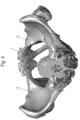
- Fig. 1-5 refers primarily to an osteosynthesis plate as a replacement of the fibrocartilaginous connection between the pubic rami in the case of a rupture of the pubic symphysis. This application is described in Fig. 4 reproduced.
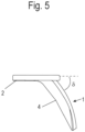
- the angle between the support surface and the connecting segment can be, for example, 130° or, in other words, protrude by an angle ⁇ of 50° relative to the fixation plate segments.
- connection of the osteosynthesis plate according to the invention allows in particular a controlled movement between the segments through a targeted dimensioning of the connecting segment.
- the two fixation plate segments and the connecting segment between said fixation plate segments are part of a one-piece osteosynthesis plate, in particular a single piece of metal. There are no joints or hinges.
- the one-piece osteosynthesis plate is constructed monolithically, i.e., without connecting seams, such as welds or the like.
- the connecting segment between the two fixation plate segments is angled between 30° and 80° relative to the two plates in the lateral plane, and between 0° and 30° relative to the long axis of each plate.
- an implant is provided as an osteosynthesis plate with two plate segments connected by a flexible connecting segment that allows controlled movement between the two plates.
Landscapes
- Health & Medical Sciences (AREA)
- Orthopedic Medicine & Surgery (AREA)
- Life Sciences & Earth Sciences (AREA)
- Surgery (AREA)
- Animal Behavior & Ethology (AREA)
- Veterinary Medicine (AREA)
- Public Health (AREA)
- Engineering & Computer Science (AREA)
- Biomedical Technology (AREA)
- Heart & Thoracic Surgery (AREA)
- General Health & Medical Sciences (AREA)
- Molecular Biology (AREA)
- Medical Informatics (AREA)
- Nuclear Medicine, Radiotherapy & Molecular Imaging (AREA)
- Neurology (AREA)
- Cardiology (AREA)
- Oral & Maxillofacial Surgery (AREA)
- Transplantation (AREA)
- Vascular Medicine (AREA)
- Surgical Instruments (AREA)
Description
- Die vorliegende Erfindung betrifft eine Osteosyntheseplatte nach dem Oberbegriff des Anspruchs 1.
- Osteosyntheseplatten, welche sich als Ersatz einer Synarthrose eignen, sind typischerweise streifenförmige oder als L-abgewinkelte flache Metallleisten. Problematisch ist, dass ein Becken oder andere Körperteile einer ständigen Bewegung unterliegen. Bei der Bewegung wirken in der Ebene der Metallleiste bei Bewegung entsprechende Zug- und Druckkräfte, die sich auf die Schrauben übertragen werden. Dadurch wird die Knochenschraube beständig hin und her bewegt, so dass sie das Bohrloch innerhalb des Knochens erweitert und sich die Schraube dadurch aus der Verankerung des Knochens lösen kann oder es kann zu einem Schraubenbruch oder Plattenbruch kommen.
- Die
DE 26 03 087 B1 offenbart eine gattungsgemäße Osteosyntheseplatte mit Fixationsplattensegmenten zur Stabilisierung einer Symphyse, welche jeweils eine Auflagenfläche zur Auflage an einem Beckenrand aufweisen und ein daraus hervorstehendes Verbindungssegment, welches derart aus dem Fixationsplattensegmenten hervorsteht, dass es geeignet ist zur Erstreckung entlang der Beckeninnenseite eines Menschen. Das Material der Osteosymphyseplatte ist thermoplastisch und wird durch Hitze weich und passt sich die Anatomie der Symphyse an. - Die
DE 102012 010 024 A1 offenbart einen Implantatträger, welcher allerdings nicht der gattungsgemäßen Ausgestaltung des Oberbegriffs des vorliegenden Erfindung entspricht. Ziel der Merkmale des Oberbegriffs ist die Definition eines Gegenstands mit welchem eine spezielle Kraftumlenkung in das Implantat bei einer Bewegung einhergeht. Die eingeleitete bewegungsbedingte Kraft wird dabei anders als bei derDE 26 03 087 B1 nicht senkrecht zur Fixationsplatte in das Verbindungssegment abgeleitet. Vielmehr wirken in derDE 10 2012 010 024 A1 durch die direkte und kürzeste Verbindung zweier Fixationsplatten, Zugkräfte auf ebendiese Fixationsplatten ein, wodurch es zur seitlichen Belastung der Verbindungselemente (Knochenschrauben und dergl.) kommt. Weiterhin besteht das offenbarte Konstrukt aus mindestens 13 Teile, die zusammengebaut werden und mittels eine Traverse Titanstab eine seitliche Verschiebung der zwei Knochenplatten erlauben. Die Bewegung findet nur in einer Ebene statt - die seitliche Ebene und das Ausmaß der Bewegung ist durch die Länge des Schlitzes in der Traverse definiert (Fig 1 , no 20). Die Traverse gleitet ohne Widerstand. - Gleiches gilt für die
US 2005/0165401 A1 . Die Platte ist eine Platte zur Stabilisierung der Acetabulumfrakturen (Frakturen der Hüftpfanne) - also eine Fraktur im Bereich des Beckens - aber örtlich 10 cm von der Symphyse entfernt. Speziell für diese Platte ist eine zusätzliche Fläche in der Mitte der Platte dessen Zweck ist die Acetabulum-Fraktur abzustützen. Die Fläche stützt Lamina Quadrilateralis ab und verhindert die Protrusion/Medialisierung des Femurkopfes. Das Konstrukt verfolgt im Aufbau, Ausführung und Zweck ein anderes Ziel als die vorliegende Erfindung. - In der
DE 10 2005 032 026 B3 wird eine Platte mit zwei Plattenabschnitten offenbart, die in verschiedenen Winkeln verbunden sind. Die Platte ist für Kieferchirurgie vorgesehen und verschiedenen Winkeln zwischen Plattenabschnitte sind die spezielle Geometrie des Kiefers angepasst. Figur 14a und 14b zeigt zwei Platten die mit einem U-förmigen Metallplatte verbunden sind. Der Zweck dieser Verbindung ist Nerven umfahren zu können, und dadurch eine Einklemmung des Nervs unter der Platte zu verhindern. Auch ist die Biegung des U-formigen Teils möglich und damit die Platte der Geometrie des Kiefers besser anpassen zu können wie aus den Absätzen [0066] und [0067] hervorgeht. Die Biegung ist somit "in plane" also entlang der Ebene der Auflagenflächen der Fixationselemente und kann daher keine axiale Verschiebung der Beckenknochen gegeneinander abfedern und stabilisieren. - Somit bildet die
DE 26 03 087 B1 den einzigen bekannten gattungsgemäßen Stand der Technik, welcher die Krafteinbringung und -umlenkung in die gewünschte Richtung überträgt. Allerdings ist die Osteosyntheseplatte der gattungsgemäßenDE 26 03 087 B1 breitflächig ausgebildet und umschließt bzw. umgreift den Beckenrand und die Beckeninnenseite wie eine Manschette. Die Oberfläche der Platte ist insbesondere auf maximale Grösse gebracht damit eine hohe Steifigkeit der Platte erreicht wird. Auch werden Schrauben nah zu der Symphyse eingeschraubt so dass die Platte eine maximale Stabilität erreicht. Darüber hinaus liegt die Platte an der äusseren Fläche des Beckens - also zwischen Haut und Knochen. - Durch die breitflächige Ausbildung insbesondere im Bereich des Verbindungssegments werden allerdings die Fixationsplatten starr fixiert. Dies ist insofern problematisch als dass die verbundenen Beckenknochen infolge einer Bewegung selbst gegeneinander eine Bewegung ausführen, so dass es bei starrer Fixierung zu einem allmählichen Lösen der Verbindungsstellen der Osteosyntheseplatte mit dem Beckenknochen kommen kann.
- Ausgehend von der vorgenannten Problemstellung ist es Aufgabe der vorliegenden Erfindung eine Osteosyntheseplatte bereitzustellen, welche eine Kraftumlenkung
- ermöglicht und teilweise auch einer bewegungsbedingten Kraft durch elastische Verformung entgegenwirkt.
- Die vorliegende Erfindung löst die vorgenannte Aufgabe durch eine Osteosyntheseplatte mit den Merkmalen des Anspruchs 1.
- Es ist eine Grundidee der vorliegenden Erfindung eine Osteosyntheseplatte nicht starr, sondern federn und zugleich ergonomisch auszubilden. Der Grad einer Federung ist dem Fachmann als Federhärte bekannt und wird üblicherweise über eine sogenannte Federkonstante angegeben. Die Federkonstante ist dabei ein Wert, der einer Feder zugesprochen wird. Man verwendet die Federkonstante, um die Feder für den gewünschten Zweck auslegen und berechnen zu können. Die Federkonstante ist eine komplexe physikalische Größe und kann durch verschiedene Faktoren der Feder beeinflusst werden. Sie errechnet sich aus der Auslenkung der Feder mit der dazu notwendigen und resultierenden Kraft. (Siehe u.a. https:/Iwww.maschinenbau-wissen.de/skript3/mechanik/kinetik/114-federkonstante). Dem Fachmann ist eine Federkonstante somit nicht als ein zu erreichendes Ergebnis, sondern als physikalische Größe und somit als technisches Merkmal zur Beschreibung eines Federelements bekannt. Federkonstanten werden daher seit Langem auch in der Patentliteratur als technische Merkmale zur Beschreibung der Weichheit oder Härte eines Federelements benutzt. Beispiele für eine Federkonstante als geeignetes Merkmal zur Charakterisierung eines Federelements sind folgende erteilte EP-Patente:
In derEP 2 704 974 B1 (Anspruch 1) wurde eine Aufwickelvorrichtung mit einer Federkonstante zwischen 0,5 und 5 N/m charakterisiert. - In der
EP 0 861 571 B1 (Anspruch 1) wurde ein Schaummaterial über seine dynamische Federkonstante von mindestens 4,4*104 N/m charakterisiert. - In der
EP 2 438 953 B1 (Anspruch 12) wurde die Feder eines zusammenziehbaren Atemschlauchs anhand seiner Federkonstante charakterisiert. - Es finden sich aber auch zahlreiche weitere Beispiele zur Nutzung der Federkonstante als technisches Merkmal in der Patentliteratur.
- Eine erfindungsgemäße Osteosyntheseplatte sollte sich als Ersatz einer Synarthrose eignen. Dabei weist die Osteosyntheseplatte zwei Fixationsplattensegmente zur Festlegung der Osteosyntheseplattes an zwei Knochen eines Beckens auf.
- Jedes der Fixationsplattensegmente definiert eine Auflagenfläche. Diese kann eben, gewölbt oder individuell auf den Patienten angepasst sein. Die Auflagefläche dient speziell im Anwendungsfall des Symphyseersatzes im Beckenbereich zur Auflage auf dem Beckenrand eines Beckenknochens, während das Verbindungselement gegenüber den Fixationsplattensegmenten derart hervorsteht, dass es sich zumindest bereichsweise entlang der Beckeninnenseite bzw. über einen Teilbereich der Beckeninnenseite, erstreckt und besonders bevorzugt daran anliegt.
- Unabhängig von dem vorgenannten bevorzugten Anwendungsfall, weist jede Auflagenfläche, unabhängig von ihrer Form zumindest einen Normalenvektor auf, welcher senkrecht zu der Auflagenfläche steht.
- Die Osteosyntheseplatte weist zudem ein Verbindungssegment auf, welches die beiden Fixationsplattensegmente miteinander verbindet und welches aus den Fixationsplattensegmenten hervorsteht. Während die Fixationsplattensegmente in Weiterführung ihrer Erstreckung zu einer theoretischen Verbindung der Fixationsplattensegmenten im kürzesten Abstand eine Verbindungsebene definieren, so liegt das Verbindungssegment vorzugsweise außerhalb dieser Verbindungsebene.
- Dabei kann das Verbindungssegment randseitig am Fixationsplattensegment angeordnet sein und um einen Winkel von mehr als 45° gegenüber einer fiktiven Verlängerung der Auflagenfläche abgewinkelt, insbesondere abgebogen, sein. Diese abgewinkelte Abbiegung bezeichnet eine Ausrichtung gegenüber einer in-Plane (Ausrichtung in der Ebene der Auflagenfläche) bzw. einer Abbiegung gegenüber der vorgenannten fiktiven Verlängerung. Sie ist als eine Angabe eines Betrags zu verstehen und kann daher auch ein Negativwert für eine Winkelangabe im streng mathematischen Sinne darstellen.
- Umgekehrt kann das Verbindungssegment vorteilhaft um weniger als 45° gegenüber dem Normalenvektor abweichen,
Die erfindungsgemäße Osteosyntheseplatte kann vorteilhaft aufgrund ihrer Elastizität die Krafteinwirkung auf die Verbindungsstelle zum Knochen auf längere Zeit verteilen, wodurch die Belastung auf die Verbindungsstelle abgedämpft wird. - Weitere vorteilhafte Ausgestaltungen sind u.a. Gegenstand der Unteransprüche.
- Ausgehend vom Fixationsplattensegment kann in einer bevorzugten Ausführungsvariante randseitig daran eine mechanische Schnittstelle als Teil des Verbindungssegments angeordnet sein, welche als ein Bogen bzw. eine Biegung ausgebildet ist. Ausgehend nach dieser mechanischen Schnittstelle verläuft das Verbindungssegment in dem vorgenannten Winkel. Die mechanische Schnittstelle nimmt dabei bezogen auf die Gesamtlänge des mechanischen Verbindungssegments weniger als 10%, vorzugsweise weniger als 5% der Gesamtlänge ein. Die mechanische Schnittstelle kann im Rahmen der vorliegenden Erfindung vorzugsweise eine Schweißstelle oder eine Biegestelle sein.
- In der weiteren Erstreckung verläuft das Verbindungssegment in einem Winkel von weniger als 45° gegenüber dem Normalenvektor. Das bedeutet, dass es auch Teilbereiche des Verbindungssegments geben kann welche einen Winkel von mehr als 45° gegenüber dem Verbindungssegment einnehmen. Allerdings ist dies bevorzugt lediglich, wie vorhergehend definiert, lediglich ein geringer Abschnitt des Verbindungssegments.
- Um zusätzlich eine Kraftverminderung der einwirkenden Kräfte zu erreichen, ist das Verbindungssegment als Federelement ausgebildet. In dieser Funktion ist das Verbindungssegment derart ausgebildet, dass ein frei-schwingendes Fixationsplattensegment der Osteosyntheseplatte im einseitig fixierten Zustand gegenüber dem zweiten Fixationsplattensegment bei Aufwendung einer Kraft von 350 N aus einer Richtung parallel zum Normalenvektor um eine Distanz Δs von zumindest 1,5 mm, vorzugsweise 1,8 bis 5,0 mm, ausgelenkt wird. Die Auslenkung und die vorhergehende Definition ersetzt dabei die Angabe einer Federkonstante zur Charakterisierung des Verbindungssegments als Federelement. Die Kraftminderung bewirkt, dass die auf die Knochenschrauben einwirkenden Kräfte verringert sind.
- Das Verbindungssegment kann vorteilhaft als ein Flachverbindungssegment ausgebildet sein mit einer mittleren Plattenstärke, welche zumindest 1,5 mal geringer ist, vorzugsweise 2-5 mal geringer ist, als die mittlere Breite des Flachsegments. Durch diese Ausgestaltung wird eine besondere mechanische Stabilität der Verbindung gewährleistet.
- Die Länge des Verbindungssegments kann zumindest doppelt so lang sein wie der kürzeste Abstand der Kanten der beiden Fixationsplattensegmente, um dadurch eine hohe Flexibilität für eine Ausgleichsverformung der Osteosyntheseplatte zu erreichen.
- Aus einem ähnlichen Grund ist es auch von Vorteil, wenn die Länge des Verbindungssegments zumindest fünfmal so lang ist wie die mittlere Breite des Verbindungssegments.
- Eine besonders gute mechanische Stabilität in Kombination mit einer optimalen Federwirkung wurden beobachtet, sofern das Verbindungssegment eine "W" oder "U"-Form aufweist.
- Bevorzugt steht das das Verbindungssegment um mehr als 45°, vorzugsweise zwischen 85-95°, gegenüber dem Fixationsplattensegment hervor. Besonders bevorzugt kann es sich dabei um eine Abbiegung gegenüber dem Fixationsplattensegment mit einem entsprechenden Biegebereich handeln.
- Die Fixationsplatten können für eine stabile und zugleich kraftverteilende Verbindung zu einem Knochen zumindest zwei, vorzugsweise drei Bohrlöcher zur Durchführung jeweils eines mechanischen Verbindungsmittels, insbesondere einer Knochenschraube aufweisen.
- Bevorzugt ist die Osteosyntheseplatte einstückig ausgebildet, um eine optimale Kraftumleitung durch das Material zu ermöglichen. Für eine Federwirkung und zur Aufteilung von Materialspannungen ist es günstig, wenn die gesamte Osteosyntheseplatte aus einem duktilen Material, besonders bevorzugt aus einem Titan und/oder einem Edelstahl und/oder einer Metalllegierung umfassend Titan und/oder Eisen besteht.
- Um eine Verträglichkeit zu verbessern ist es von Vorteil, wenn die Osteosyntheseplatte zumindest abschnittsweise eine Beschichtung, insbesondere aus einem resorbierbaren Material oder mit einem entzündungshemmenden Wirkstoff, aufweist. Dies kann insbesondere im Bereich der Auflageflächen sein.
- Fertigungstechnisch ist es günstig, wenn die Fixationsplattensegmente und das Verbindungssegment die gleiche Plattenstärke aufweisen. Geringe Abweichungen von 10% der Plattenstärke oder weniger sind dabei zu vernachlässigen. Darüber hinaus werden dadurch keine zusätzlichen mechanischen Schwachstellen geschaffen.
- Die Fixationsplattensegmente weisen eine Längserstreckung und eine Quererstreckung senkrecht dazu auf, wobei das Verbindungssegment randseitig und mittig bezogen auf die Längserstreckung angeordnet ist. Dadurch ist die Kraftübertragung auf alle Bohrlöcher des Fixationsplattensegments bei einer Verformung gleichmäßig verteilt.
- Bevorzugt ist eine Schnittstelle zwischen jeweils einem Fixationsplattensegment und dem Verbindungssegment als eine Biegung ausgebildet, vorzugsweise mit einem Biegeradius, welcher zumindest größer, besonders bevorzugt zumindest doppelt so groß, wie die mittlere Plattenstärke des Verbindungssegments, so dass eine Kraftumlenkung optimiert erfolgt.
- Für eine zusätzliche Verformung in eine zweite Dimension kann das Verbindungssegment gewölbt und zu den Fixationspunkten der Fixationsplattensegmente hin konvex ausgebildet sein. Dadurch wird eine noch bessere Kraftminderung erreicht.
- Wie aus sich bereits aus dem Kontext der Beschreibung ergibt ist eine Osteosyntheseplatte im Rahmen der vorliegenden Erfindung nicht als ausschließlich ebenes Objekt zu verstehen, sondern es kann eines oder mehrere Teilsegmente, beispielsweise ein abgebogenes Verbindungssegment, aufweisen, welche insbesondere winkelig aus einer Plattenebene, vorzugsweise auch zu mehr als 45°, insbesondere senkrecht, hervorstehen können.
- Weitere Vorteile, Merkmale und Einzelheiten einer erfindungsgemäßen Osteosyntheseplatte ergeben sich aus der nachfolgenden Beschreibung, in der ein Ausführungsbeispiel der Erfindung anhand der beiliegenden Zeichnungen näher erläutert wird. Der Fachmann wird die in den Zeichnungen, der Beschreibung und den Ansprüchen in Kombination offenbarten Merkmale zweckmäßigerweise auch einzeln betrachten und zu sinnvollen weiteren Kombinationen zusammenfassen. Insbesondere gibt es eine Vielzahl von Möglichkeiten, diese im Rahmen der vorliegenden Erfindung abzuwandeln und weiterzubilden. Es zeigen:
- Fig. 1
- eine Ansicht einer Ausführungsvariante einer erfindungsgemäßen Osteosyntheseplattes in die koronare Ebene bzw. antero-posteriore Ebene;
- Fig. 2
- eine Ansicht auf die erfindungsgemäße Osteosyntheseplatte in axialer Ebene;
- Fig. 3
- eine Kraftverteilungsanzeige in der Perspektivansicht auf die erfindungsgemäße Osteosyntheseplatte;
- Fig. 4
- eine schematische Darstellung der Osteosyntheseplattes im montierten Zustand in einer Anwendung als Ersatz einer Symphyse; und
- Fig 5
- eine Ansicht auf die erfindungsgemäße Osteosyntheseplatte der
Fig. 1-4 in sagittaler Ebene. - Das in den
Fig. 1-5 dargestellte Ausführungsbeispiel zeigt eine Osteosyntheseplatte 1 zur Fixierung eines Beckens insbesondere aufgrund eines traumatisch-bedingten Ruptur der Symphyse. - Eine derartige Verletzung sorgt für eine Instabilität des Beckenrings und muss auf chirurgische Weise stabilisiert werden. Bekannte Knochenplatten sind leistenförmig gerade oder winklig ausgebildet.
- Die erfindungsgemäße Osteosyntheseplatte 1 weist ein erstes und eins zweite Fixationsplattensegment 2 und 3 auf, sowie ein Flachverbindungssegment 4 auf, welche zwischen den beiden Fixationsplatten 2, 3 angeordnet ist und diese miteinander verbindet. Das Flachverbindungssegment 4 weist eine mittlere Plattendicke Pd2 von vorzugsweise zumindest 2 mm, vorzugsweise zwischen 2,5 bis 5 mm, insbesondere 3 mm +/- 0,2 mm, auf. Besonders bevorzugt ist die Plattendicke Pd2 des Flachverbindungssegments 4 im Wesentlichen, also über mehr als 90% der Länge l1 des Flachverbindungssegments 4, einheitlich.
- Das Flachverbindungssegment 4 weist vorzugsweise mittlere Breite b1 von vorzugsweise zumindest 5 mm, vorzugsweise zwischen 7 - 15 mm, insbesondere 9 mm +/-0.8 mm, auf. Besonders bevorzugt ist die Plattendicke Pd2 des Fachverbindungssegments 4 im Wesentlichen, also über mehr als 90% der Länge l1 des Flachverbindungssegments 4, einheitlich.
- Die erste und die zweite Fixationsplatte 2 und 3 definiert jeweils eine erste und eine zweite Auflagenfläche 100 mit einem Normalenvektor N. Die beiden Auflageflächen 100 können zueinander parallel oder auf einer gemeinsamen Ebene liegen. Allerdings können die beiden Auflagenflächen 100 auch gebogen ausgebildet und/oder winklig zueinander angeordnet sein.
- Ausgehend von einem der beiden Normalenvektoren N, oder einem parallel zu diesem Normalenvektor verlaufenden Vektor, steht das Flachverbindungssegment 4 mit einem Winkel α von weniger als 45°, insbesondere in einem Winkel von weniger als 5°, gegenüber dem besagten jeweiligen Normalenvektor oder dem parallelen Vektor aus der jeweiligen Fixationsplatte 2 oder 3 hervor. In
Fig. 1 steht das Flachverbindungssegment 4 um diesen Winkel aus der Zeichnungsebene hervor. Das Hervorstehen erfolgt derart, dass ein and den Fixationsplattensegmenten angeordnetes randseitiges Materialsegment, das Flachverbindungssegment, gegenüber den Fixationsplattensegmenten abgebogen ist. Die Biegung wird nachfolgend auch als mechanische Schnittstelle 12 bezeichnet und ist ein Abschnitt des Flachverbindungssegments 4. - Jede der Fixationsplatte 2 und 3 verfügt zumindest über einen, vorzugsweise zumindest drei Fixationspunkte 5 zur Fixierung der besagten Fixationsplatte an einem Knochen, insbesondere einem Beckenknochen. Die Fixationspunkte 5 können als Bohrlöcher ausgebildet sein, durch welche über entsprechende Schrauben 6, z.B. Knochenschrauben, eine Fixierung mit dem Knochen gelingt.
- Das Flachverbindungssegment 4 ist dabei vorzugsweise derart ausgebildet, dass es eine größere Länge l1 aufweist, als der kürzeste direkte Abstand r zwischen zwei an geringsten beabstandete Fixationspunkte 5 zwischen den zwei Fixationsplattensegmenten 2 und 3. Mit anderen Worten, der kürzeste Abstand r je von einem Fixationspunkt 5 der erste Fixationsplatte 2 zu einem Fixationspunkt 5 der zweiten Fixationsplatte 3 wird ermittelt. Die Länge l1 des Flachverbindungssegments 4 ist größer als dieser Abstand r.
- Die Osteosyntheseplatte 1 ist vorzugsweise einstückig ausgebildet und besteht aus einem duktilen Werkstoff, vorzugsweise einem Metall, insbesondere aus Titan und/oder Edelstahl oder einer Legierung mit zumindest einem der beiden Metalle Titan und/oder Eisen.
- Die Fixationsplattensegmente 2, 3 in der Variante der
Fig. 1-3 ist als Dreilochplatte ausgebildet, das heißt sie weist drei Bohrungen zur Durchführung von Knochenschrauben 6 und zur Fixation der Osteosyntheseplatte an den zwei Beckenknochen 13, welche durch einen kompletten oder nicht-kompletten Ruptur der Symphyse voneinander getrennt wurden. Die Bohrungen sind in Längsrichtung des Fixationsplattensegments 2 oder 3 hintereinander angeordnet. Die Bohrungen entsprechen den vorgenannten Fixationspunkten 5. Die Bohrungen können so gewählt werden, dass sie zur Durchführung von Knochenschrauben zwischen 2-5 mm Durchmesser, vorzugsweise 3-4 mm, bestimmt sind. - Das Flachverbindungssegment 4 geht randseitig auf Höhe der mittleren Bohrung von dem Fixationsplattensegment 2, 3 ab und ist in einem im Wesentlichen senkrechten Winkel von dem Fixationsplattensegment 2, 3 abgewinkelt bzw. gebogen.
- Das Flachverbindungssegment 4 weist ausgehend von dem Fixationsplattensegment 2 einen ersten Bereich 6 auf mit einem ersten negativen Anstieg bis zu einen ersten Minimum 7, wobei der negative Anstieg von dem Fixationsplattensegment weggerichtet ist.
- Sodann weist das Flachverbindungssegment 4 einen zweiten Bereich 8 mit einem ersten positiven Anstieg auf, welcher bis zu einem ersten Maximum 9 verläuft. Diese Länge dieses zweiten Bereichs 8 ist geringer, vorzugsweise um mehr als 30% geringer als die Länge des ersten Bereichs. Der positive Anstieg ist dabei zum Fixationsplattensegment 2 hin gerichtet. Das Maximum 9 weist somit einen Abstand zum ersten und zweiten Fixationsplattensegment 2 und 3 und zu deren Verbindungsachse auf.
- Sodann weist das Flachverbindungssegment 4 einen dritten Bereich 10 mit einem zweiten negativen Anstieg auf, welcher wiederum bis zu einem zweiten Minimum 11 verläuft. Der erste und der dritte Bereich 6 und 7 sind dabei im Wesentlichen gleich lang. Die Minima 7 und 11 sind im entspannten Zustand der Osteosyntheseplatte im Wesentlichen auf gleicher Höhe. Das Maximum 9 ist im gleichen Abstand zu den beiden Minima 7 und 11 angeordnet. Die Form des Flachverbindungssegments 4 entspricht der eines "W".
- Wie bereits zuvor erläutert, jedoch nicht in den Figuren dargestellt, kann das Flachverbindungssegment in einer alternativen Ausführungsvariante auch die Form eines "U" aufweisen.
- Die maximale Breite b3 des "W"'s entspricht dabei vorzugweise zumindest 30 mm, besonders bevorzugt zwischen 35-60 mm, besonders bevorzugt 45 mm +/- 5 mm. Die maximale Höhe h des "W"'s, bzw. die Länge des ersten Bereichs 6, gemessen von der Oberfläche am Fixationsplattensegment 2 an, beträgt vorzugsweise zumindest 15 mm, vorzugsweise 20-45 mm, besonders bevorzugt 30 mm +/- 3 mm.
- Allgemein formuliert ist in einer bevorzugten Ausführungsvariante der Erfindung die Breite "W" des Flachverbindungssegments 4 größer als dessen Höhe "H".
- Die Form des Flachverbindungssegments 4 ist zudem konvex, bezogen auf die Position der Fixationsplattensegmente 2 und 3.
- Die Länge l2 des Fixationsplattensegments 2 beträgt vorzugsweise zwischen 25-45 mm, vorzugsweise 40 mm +/- 4 mm. Die mittlere Breite des Fixationsplattensegments b2 über seine gesamte Länge beträgt vorzugsweise zwischen 6-13 mm, vorzugsweise 10 mm +/- 1mm.
- Der Abstand r der Fixationsplattensegmente 2, 3 von Rand zu Rand ist vorzugsweise weniger als die Längserstreckung eines Fixationsplattensegments. Er kann vorzugsweise zwischen 6-10 mm, vorzugsweise 8 mm +/- 0,5 mm, betragen. Der Abstand der Fixationsplattensegmente 2, 3 kann allerdings unter Verformung und Ausbildung von Rückstellkräften variieren. Der vorgenannte Abstand bezieht sich auf eine Osteosyntheseplatte im ungespannten Zustand und unmontierten Zustand. Im unmontierten Zustand ist die Osteosyntheseplatte noch nicht an einem oder mehreren Knochen festgelegt.
- Die mittlere Plattendicke Pd1 der Fixationsplattensegmente 2, 3 kann der mittleren Plattendicke des Flachverbindungssegments von Plattendicke von zumindest 2 mm, vorzugsweise zwischen 2,5 bis 5 mm, insbesondere 3 mm +/- 0,2 mm, entsprechen.
- Alternativ zur bevorzugten Variante der W-Form der Osteosyntheseplatte 1 sind auch anderen Formen, wie z.B. eine U-Form oder eine V-Form vorstellbar. Die vorgenannten Bezeichnungen wie mittlere Breite oder mittlere Plattendicke impliziert, dass eine Schwankung im Verlauf des jeweiligen Segments auftreten kann und dass im Fall einer solchen Schwankung die Ermittlung eines Mittelwertes mit einer Messung der Werte an unterschiedlichen Positionen des jeweiligen Segments erforderlich ist. Die Angaben wie Länge, Breite usw. beziehen sich stets auf eine Osteosyntheseplatte im unmontierten und unbelasteten bzw. unverformten Zustand.
- Aus den vorgenannten Werten lässt sich ableiten, dass die Breite des Flachverbindungssegments 4 zumindest 3-mal so groß, vorzugsweise 4-8 mal so groß, ist wie der Abstand der beiden Fixationsplattensegmente 2, 3 von Rand zu Rand.
- Die Osteosyntheseplatte wirkt aufgrund seiner konstruktiven Ausgestaltung als federndes Verbindungsteil, welches einen Bewegungsausglich zwischen den Beckenknochen herstellt und zugleich hinreichend mechanische Festigkeit besitzt, um eine Aufweitung des Abstands der Beckenknochen im Bereich der Symphyse zu verhindern.
- Die Federwirkung ist für diesen Bereich optimiert, so dass die Osteosyntheseplatte die Rückstell- und Zugkräfte einer Symphyse ersetzen kann. Hierzu wurden Tests durchgeführt.
- Im Rahmen des Tests wurde eines der beiden Fixationsplattensegmente (rechter Schenkel) fixiert, insbesondere verschraubt, und das zweite Fixationsplattensegment (linker Schenkel) frei schwingend war. Die Situation wird in
Fig. 3 wiedergegeben. - Erfolgt nun eine Druckkraft F in Richtung des Normalenvektors auf die der Auflagenfläche 100 entgegengesetzten Oberfläche des Fixationsplattensegments 2 und parallel zu diesem Vektor, so verformt sich die Osteosyntheseplatte unter Ausbildung einer Rückstellkraft. Bei Entfernen der Druckkraft kehrt die Osteosyntheseplatte 1 in ihre Ausgangsstellung AS zurück.
- Sodann wurden zur Bewegungssimulation 1200 Vollzyklen über 250 Sekunden auf das frei schwingende Fixationsplattensegment angewandt. Ein Vollzyklus besteht aus der Anwendung einer Druckkraft z.B. durch eine Druckstange, auf das Fixationsplattensegment bei einer definierten Kraft und aus der Rückkehr der Osteosyntheseplatte in seine Ausgangsstellung beim Entfernen der Druckkraft.
- Die durchschnittliche applizierte Druckkraft betrug 351,5 N und führte zu einer Verformung Δs von 2,885 mm. Diese Verformung entspricht der Höhendifferenz des freischwingenden Fixationsplattensegments gegenüber seiner Ausgangslage. Aus
Fig. 3 sind in schraffierter Darstellung die unterschiedliche Kraftverteilung innerhalb der Osteosyntheseplatte zu erkennen. Eine plastische Verformung konnte dabei nicht beobachtet werden, da es keine Varianz der Ausgangslage gab. - In einem zweiten Versuch wurden sodann 9999 Vollzyklen durchgeführt mit einer durchschnittlichen Druckkraft F von 357,6 N. Die Auslenkung bzw. Verformung Δs des frei schwingenden Fixationsplattensegments gegenüber seiner Ausgangslage bzw. Ausgangsstellung AS betrug 2,945 mm. In diesem Fall konnte eine geringfügige vernachlässigbare Verformung von 0,061 mm beobachtet werden.
- Somit kann die Osteosyntheseplatte bei Einwirkungen von 10000 Vollzyklen bei einer Kraft von etwa 350 N als formstabil bezeichnet werden.
- Experimente mit gesunden Probanden haben zudem gezeigt, dass die Symphyse bei dem Gangzyklus mit 170 N alternierend belastet wird und beim Rennen Maximalbelastungen bei erwachsenen bis 370 N entstehen und zu einer Bewegung von etwa 2-3 mm führt. Diese Kräfte können ideal auch durch die erfindungsgemäße Osteosyntheseplatte aufgenommen und entsprechend abgefedert werden.
- Die Verformung Δs der freischwingenden Fixationsplattensegments der einseitig fixierten Osteosyntheseplatte bei Ausübung einer Kraft auf dieses Fixationsplattensegment in Richtung des Normalenvektors beträgt vorzugsweise zwischen 1,8 bis 5,0 mm bei Aufwendung einer Kraft von 350N.
- Aus der
Fig. 3 erkennt man eine Kraftverteilung bei einer Kraftapplikation auf das frei schwingende Fixationsplattensegment 2. Die Dichte der Punktierung gibt den Umfang der Materialspannungen in Antwort auf die Krafteinwirkung an. Wie man erkennt ist die Krafteinwirkung im Bereich der Schnittstelle 12 und dem fixierten Fixationsplattensegment am Größten. Eine Materialspannung in diesem Bereich führt zu einer axial-gerichteten Kraft, also auf die nicht-dargestellten Schraubenköpfe und nicht als seitlich gerichtete Kraft entlang der Ebene des Fixationsplattensegments, welche für allmähliche Aufweitung und Lockerung der Verbindung zwischen Schraube und Knochen führen würde. - Das Beispiel der
Fig. 1-5 bezieht sich vornehmlich auf eine Osteosyntheseplatte als Ersatz der fibrokartilaginösen Verbindung zwischen den Schambeinästen bei einer Ruptur der Symphyse. Dieser Anwendungsfall wird inFig. 4 wiedergegeben. - Wie aus
Fig. 5 erkennbar, kann der Winkel zwischen Auflagefläche und Verbindungssegment beispielsweise 130° betragen oder, anders ausgedrückt, um einen Winkel δ von 50° gegenüber den Fixationsplattensegmenten hervorstehen. - Die Verbindung der erfinungsgemäßen Osteosyntheseplatte erlaubt insbesondere eine kontrollierte Bewegung zwischen den Segmenten durch eine gezielte Dimensionierung des Verbindungsegmentes.
- Die zwei Fixationsplattensegmente und das Verbindungssegment zwischen den besagten Fixationsplattensegmenten sind Teil einer einstückigen Osteosyntheseplatte, insbesondere eines Stücks Metall. Es gibt keine Sammlungen oder Scharnieren. Besonders bevorzugt ist die einstückige Osteosyhtheseplatte monolithisch, also ohne Verbindungsnahten z.B. Schweißnahten oder dergl. augebaut.
- Das Verbindungssegment zwischen den zwei Fixationsplattensegmenten ist durch die anatomischen Ansprüche des Beckens zwischen 30° und 80° im Vergleich zu den zwei Platten in der Seitenebene angewinkelt, und zwischen 0° und 30° im Vergleich zur Längsachse jeder Platte angewinkelt.
- Insgesamt wird ein Implantat als Osteosyntheseplatte mit zwei Plattensegmenten bereitgestelt die mit einem flexiblen Verbindungssegment verbunden sind, die eine kontrollierte Bewegung zwischen den zwei Platten erlaubt.
-
- 1
- Osteosyntheseplatte
- 2
- Fixationsplattensegment
- 3
- Fixationsplattensegment
- 4
- Flachverbindungssegment
- 5
- Fixationspunkt
- 6
- erster Bereich
- 7
- erstes Minimum
- 8
- zweiter Bereich
- 9
- erstes Maximum
- 10
- dritter Bereich
- 11
- zweites Minimum
- 12
- Schnittstelle / Biegung
- 13
- Beckenknochen
- 100
- Auflagenfläche
- Pd1
- Plattendicke (Fixationsplattensegment)
- Pd2
- Plattendicke (Flachverbindungssegment)
- N
- Normalenvektor
- F
- Kraftrichtung
- Δs
- Verformungsweg
- l1
- Gesamtlänge (Flachverbindungssegment)
- b
- Breite (Flachverbindungssegment)
- α
- Winkel
- δ
- Winkel
- r
- kürzester Abstand zweier Fixationspunkte
- bmax
- maximale Breite des Flachverbindungssegments
- h
- Höhe des Flachverbindungssegments
- l2
- Länge des Fixationsplattensegments
- b2
- Breite des Fixationsplattensegments
- AS
- Ausgangsstellung
Claims (13)
- Osteosyntheseplatte (1) als Ersatz einer Synarthrose in Form einer Symphyse, wobei die Osteosyntheseplatte (1) zwei Fixationsplattensegmente (2, 3) zur Festlegung der Osteosyntheseplatte (1) an zwei Knochen aufweist,wobei die Osteosyntheseplatte (1) ein Verbindungssegment aufweist, welches die beiden Fixationsplattensegmente (2, 3) miteinander verbindet,wobei das Verbindungssegment aus den Fixationsplattensegmenten hervorstehtwobei jedes der Fixationsplattensegmente (2, 3) eine Auflagenfläche (100) zur Auflage des Fixationsplattensegments (2, 3) an einem Beckenrand definiert und wobei das Verbindungssegment ausgebildet ist zur Erstreckung entlang der Beckeninnenseite,dadurch gekennzeichnet, dass das Verbindungssegment derart ausgebildet ist, dass ein frei-schwingendes Fixationsplattensegment (2) der Osteosyntheseplatte (1) im einseitig fixierten Zustand der Osteosyntheseplatte (1) gegenüber dem zweiten Fixationsplattensegment (3) bei Aufwendung einer Kraft von 350 N aus einer Richtung parallel zum Normalenvektor (N) der Auflagenfläche (100) des Fixationsplattensegments (2) um eine Distanz Δs von zumindest 1,5 mm, vorzugsweise 1,8 bis 5,0 mm, ausgelenkt wird.
- Osteosyntheseplatte (1) nach Anspruch 1, dadurch gekennzeichnet, dass die Auflagenfläche (100) einen Normalenvektor (N) aufweist, welcher senkrecht zu der Auflagenfläche (100) steht, und wobei das Verbindungssegment zumindest bereichsweise um einen Winkel (α) von weniger als 45° gegenüber dem Normalenvektor (N) der Auflagenfläche (100) oder einem dazu parallel-verschobenen Vektor gegenüber dem Fixationsplattensegment (2, 3) abgewinkelt ist.
- Osteosyntheseplatte nach einem der vorhergehenden Ansprüche 1 oder 2, dadurch gekennzeichnet, dass das Verbindungssegment als ein Flachverbindungssegment (4) ausgebildet ist mit einer mittleren Plattenstärke (Pd2), welche zumindest 1,5 mal geringer ist, vorzugsweise 2-5 mal geringer ist, als die mittlere Breite (b1) des Flachverbindungssegments (4).
- Osteosyntheseplatte nach einem der vorhergehenden Ansprüche, dadurch gekennzeichnet, dass die Länge (11) des Verbindungssegments zumindest doppelt so lang ist wie der kürzeste Abstand r der Ränder der beiden Fixationsplattensegmente (2, 3).
- Osteosyntheseplatte nach einem der vorhergehenden Ansprüche, dadurch gekennzeichnet, dass die Länge (11) des Verbindungssegments zumindest fünfmal so lang ist wie die mittlere Breite (b1) des Verbindungssegments.
- Osteosyntheseplatte nach einem der vorhergehenden Ansprüche, dadurch gekennzeichnet, dass das Verbindungssegment eine "W" oder "U"-Form aufweist.
- Osteosyntheseplatte nach einem der vorhergehenden Ansprüche, dadurch gekennzeichnet, dass das Verbindungssegment um einem Winkel (δ) von mehr als 45°, vorzugsweise 85-95°, gegenüber einer fiktiven Verlängerung der Auflagenfläche (100) eines jedem der Fixationsplattensegmente (2, 3), gegenüber dieser Verlängerung abgebogen ist.
- Osteosyntheseplatte nach einem der vorhergehenden Ansprüche, dadurch gekennzeichnet, dass die Fixationsplatten (2, 3) zumindest zwei, vorzugsweise drei Bohrlöcher zur Durchführung jeweils eines mechanischen Verbindungsmittels, insbesondere einer Knochenschraube aufweisen.
- Osteosyntheseplatte nach einem der vorhergehenden Ansprüche, dadurch gekennzeichnet, dass die Osteosyntheseplatte (1) einstückig ausgebildet ist und vorzugsweise aus einem duktilen Material, besonders bevorzugt aus einem Titan und/oder einem Edelstahl und/oder einer Metalllegierung umfassend Titan und/oder Eisen besteht.
- Osteosyntheseplatte nach einem der vorhergehenden Ansprüche, dadurch gekennzeichnet, dass die Fixationsplattensegmente (2, 3) und das Verbindungssegment die gleiche Plattenstärke (Pd1, Pd2) aufweisen.
- Osteosyntheseplatte nach einem der vorhergehenden Ansprüche, dadurch gekennzeichnet, dass die Fixationsplattensegmente (2, 3) eine Längserstreckung (l2) und eine Quererstreckung (b2) senkrecht dazu aufweisen, wobei das Verbindungssegment randseitig und mittig bezogen auf die Längserstreckung (l2) angeordnet ist.
- Osteosyntheseplatte nach einem der vorhergehenden Ansprüche, dadurch gekennzeichnet, dass eine Schnittstelle (12) zwischen jeweils einem Fixationsplattensegment (2 oder 3) und dem Verbindungssegment als eine Biegung ausgebildet ist, vorzugsweise mit einem Biegeradius, welcher zumindest größer, besonders bevorzugt zumindest doppelt so groß, wie die mittlere Plattenstärke (Pd2) des Verbindungssegments.
- Osteosyntheseplatte nach einem der vorhergehenden Ansprüche, dadurch gekennzeichnet, dass das Verbindungssegment gewölbt und zu Fixationspunkten (5) der Fixationsplattensegmente (2, 3) hin konvex ausgebildet ist.
Applications Claiming Priority (2)
| Application Number | Priority Date | Filing Date | Title |
|---|---|---|---|
| EP21162117.2A EP4056132A1 (de) | 2021-03-11 | 2021-03-11 | Osteosyntheseplatte geeignet als ersatz einer synarthrose |
| PCT/EP2022/055474 WO2022189267A1 (de) | 2021-03-11 | 2022-03-03 | Osteosyntheseplatte geeignet als ersatz einer synarthrose |
Publications (2)
| Publication Number | Publication Date |
|---|---|
| EP4304503A1 EP4304503A1 (de) | 2024-01-17 |
| EP4304503B1 true EP4304503B1 (de) | 2025-05-14 |
Family
ID=74871304
Family Applications (2)
| Application Number | Title | Priority Date | Filing Date |
|---|---|---|---|
| EP21162117.2A Withdrawn EP4056132A1 (de) | 2021-03-11 | 2021-03-11 | Osteosyntheseplatte geeignet als ersatz einer synarthrose |
| EP22710560.8A Active EP4304503B1 (de) | 2021-03-11 | 2022-03-03 | Osteosyntheseplatte als ersatz einer synarthrose in form einer symphyse |
Family Applications Before (1)
| Application Number | Title | Priority Date | Filing Date |
|---|---|---|---|
| EP21162117.2A Withdrawn EP4056132A1 (de) | 2021-03-11 | 2021-03-11 | Osteosyntheseplatte geeignet als ersatz einer synarthrose |
Country Status (3)
| Country | Link |
|---|---|
| US (1) | US12491014B2 (de) |
| EP (2) | EP4056132A1 (de) |
| WO (1) | WO2022189267A1 (de) |
Family Cites Families (9)
| Publication number | Priority date | Publication date | Assignee | Title |
|---|---|---|---|---|
| US5792998A (en) | 1993-04-19 | 1998-08-11 | Cabot Safety Intermediate Corporation | Acoustical hearing protective devices utilizing dynamically stiff foam and methods of producing same |
| US20050165401A1 (en) * | 2004-01-26 | 2005-07-28 | Larry Pack | Pelvic fixation plate |
| DE102005032026B3 (de) * | 2005-07-08 | 2006-12-14 | Stryker Leibinger Gmbh & Co. Kg | Osteosyntheseplatte mit schräg zur Plattenebene verlaufenden Durchgangsöffnungen |
| AU2008221506B2 (en) | 2007-09-20 | 2011-01-20 | ResMed Pty Ltd | Retractable Tube for CPAP |
| EP2494934B1 (de) * | 2011-03-04 | 2015-12-16 | Stryker Trauma SA | Knochenplatte |
| DE102011075142A1 (de) | 2011-05-03 | 2012-11-08 | Polycine Gmbh | Aufwickelvorrichtung |
| DE102012010024A1 (de) * | 2012-05-21 | 2013-11-21 | Metasys Medizintechnik Gmbh | Implantatträger |
| KR20170050468A (ko) * | 2015-10-30 | 2017-05-11 | 가톨릭대학교 산학협력단 | 하악지에 고정되는 교정 플레이트 |
| CN112107356A (zh) * | 2020-10-14 | 2020-12-22 | 重庆医科大学附属第一医院 | 一种新型耻骨联合解剖接骨板及其设计方法 |
-
2021
- 2021-03-11 EP EP21162117.2A patent/EP4056132A1/de not_active Withdrawn
-
2022
- 2022-03-03 WO PCT/EP2022/055474 patent/WO2022189267A1/de not_active Ceased
- 2022-03-03 EP EP22710560.8A patent/EP4304503B1/de active Active
- 2022-03-03 US US18/280,020 patent/US12491014B2/en active Active
Also Published As
| Publication number | Publication date |
|---|---|
| EP4304503A1 (de) | 2024-01-17 |
| EP4056132A1 (de) | 2022-09-14 |
| WO2022189267A1 (de) | 2022-09-15 |
| US20240138889A1 (en) | 2024-05-02 |
| US12491014B2 (en) | 2025-12-09 |
Similar Documents
| Publication | Publication Date | Title |
|---|---|---|
| DE69623129T2 (de) | Modulare prothese | |
| DE69209494T2 (de) | Implantat aus einer expandierbaren zwischenwirbelscheibe | |
| DE69919912T2 (de) | Anordnung zur Stabilisierung zweier nebeneinanderliegender Wirbel der Wirbelsäule | |
| DE69715141T2 (de) | Orthopedische Prothese mit Knochenschrauben und Zement | |
| DE69635746T2 (de) | Gelenkprothesenerhöhungssystem | |
| DE69533780T2 (de) | Einrichtung zur Wirbelsäulenfixation | |
| DE60030980T2 (de) | Orthopädische implantatanordnung | |
| DE10220591B4 (de) | Gelenkprothese mit Zwischenelement mit unterschiedlichen Krümmungsradien | |
| DE69514337T2 (de) | Implantat zur stabilisierung von bandscheiben, und eine vorrichtung zum erleichterten einsetzen des implantats | |
| DE10348329B3 (de) | Stabförmiges Element für die Anwendung in der Wirbelsäulen- oder Unfallchirurgie,Stabilisierungseinrichtung mit einem solchen stabförmigen Element und Herstellungsverfahren für das stabförmige Element | |
| EP1335684B1 (de) | Kniegelenk-endoprothese-system | |
| DE69228190T2 (de) | Femorales hüftimplantat mit verringerter steifheit | |
| DD300402A5 (de) | Prothese | |
| EP1523281A1 (de) | Vorrichtung zur dynamischen stabilisierung von knochen oder knochenfragmenten, insbesondere r ckenwirbelk rpern | |
| EP1363563A1 (de) | Gelenkprothese | |
| DE69300303T2 (de) | Vorrichtung zum Immobilisieren angrenzender spinaler Körper. | |
| EP1168989B1 (de) | Gelenkkopfprothese und bausatz zur bildung einer solchen | |
| EP0375599A2 (de) | Endoprothese | |
| DE102004024046A1 (de) | Zwischenwirbel-Abstandshalter | |
| DE69211077T2 (de) | Knieprothese mit einem Gelenk zwischen den femoralen und tibialen Komponenten und den entsprechenden endomodularen Schäften | |
| EP0423280B1 (de) | Fixierungssystem für röhrenknochenfrakturen | |
| DE102019000965A1 (de) | Knochenverankerungsvorrichtung für den Pedikelzugang | |
| DE102011106653A1 (de) | Verankerungselement mit funktionalem Schaft und modulares Veranderungssystem | |
| EP1121903A2 (de) | Osteosynthese-Platte | |
| EP1792577B1 (de) | Chirurgische Stabilisierungseinrichtung mit einem stabförmigen Element |
Legal Events
| Date | Code | Title | Description |
|---|---|---|---|
| STAA | Information on the status of an ep patent application or granted ep patent |
Free format text: STATUS: UNKNOWN |
|
| STAA | Information on the status of an ep patent application or granted ep patent |
Free format text: STATUS: THE INTERNATIONAL PUBLICATION HAS BEEN MADE |
|
| PUAI | Public reference made under article 153(3) epc to a published international application that has entered the european phase |
Free format text: ORIGINAL CODE: 0009012 |
|
| STAA | Information on the status of an ep patent application or granted ep patent |
Free format text: STATUS: REQUEST FOR EXAMINATION WAS MADE |
|
| 17P | Request for examination filed |
Effective date: 20230831 |
|
| AK | Designated contracting states |
Kind code of ref document: A1 Designated state(s): AL AT BE BG CH CY CZ DE DK EE ES FI FR GB GR HR HU IE IS IT LI LT LU LV MC MK MT NL NO PL PT RO RS SE SI SK SM TR |
|
| DAV | Request for validation of the european patent (deleted) | ||
| DAX | Request for extension of the european patent (deleted) | ||
| GRAP | Despatch of communication of intention to grant a patent |
Free format text: ORIGINAL CODE: EPIDOSNIGR1 |
|
| STAA | Information on the status of an ep patent application or granted ep patent |
Free format text: STATUS: GRANT OF PATENT IS INTENDED |
|
| INTG | Intention to grant announced |
Effective date: 20241211 |
|
| GRAS | Grant fee paid |
Free format text: ORIGINAL CODE: EPIDOSNIGR3 |
|
| GRAA | (expected) grant |
Free format text: ORIGINAL CODE: 0009210 |
|
| STAA | Information on the status of an ep patent application or granted ep patent |
Free format text: STATUS: THE PATENT HAS BEEN GRANTED |
|
| AK | Designated contracting states |
Kind code of ref document: B1 Designated state(s): AL AT BE BG CH CY CZ DE DK EE ES FI FR GB GR HR HU IE IS IT LI LT LU LV MC MK MT NL NO PL PT RO RS SE SI SK SM TR |
|
| REG | Reference to a national code |
Ref country code: GB Ref legal event code: FG4D Free format text: NOT ENGLISH |
|
| REG | Reference to a national code |
Ref country code: CH Ref legal event code: EP |
|
| REG | Reference to a national code |
Ref country code: IE Ref legal event code: FG4D Free format text: LANGUAGE OF EP DOCUMENT: GERMAN |
|
| REG | Reference to a national code |
Ref country code: DE Ref legal event code: R096 Ref document number: 502022003949 Country of ref document: DE |
|
| REG | Reference to a national code |
Ref country code: NL Ref legal event code: MP Effective date: 20250514 |
|
| PG25 | Lapsed in a contracting state [announced via postgrant information from national office to epo] |
Ref country code: FI Free format text: LAPSE BECAUSE OF FAILURE TO SUBMIT A TRANSLATION OF THE DESCRIPTION OR TO PAY THE FEE WITHIN THE PRESCRIBED TIME-LIMIT Effective date: 20250514 Ref country code: PT Free format text: LAPSE BECAUSE OF FAILURE TO SUBMIT A TRANSLATION OF THE DESCRIPTION OR TO PAY THE FEE WITHIN THE PRESCRIBED TIME-LIMIT Effective date: 20250915 Ref country code: ES Free format text: LAPSE BECAUSE OF FAILURE TO SUBMIT A TRANSLATION OF THE DESCRIPTION OR TO PAY THE FEE WITHIN THE PRESCRIBED TIME-LIMIT Effective date: 20250514 |
|
| REG | Reference to a national code |
Ref country code: LT Ref legal event code: MG9D |
|
| PG25 | Lapsed in a contracting state [announced via postgrant information from national office to epo] |
Ref country code: NO Free format text: LAPSE BECAUSE OF FAILURE TO SUBMIT A TRANSLATION OF THE DESCRIPTION OR TO PAY THE FEE WITHIN THE PRESCRIBED TIME-LIMIT Effective date: 20250814 Ref country code: GR Free format text: LAPSE BECAUSE OF FAILURE TO SUBMIT A TRANSLATION OF THE DESCRIPTION OR TO PAY THE FEE WITHIN THE PRESCRIBED TIME-LIMIT Effective date: 20250815 |
|
| PG25 | Lapsed in a contracting state [announced via postgrant information from national office to epo] |
Ref country code: PL Free format text: LAPSE BECAUSE OF FAILURE TO SUBMIT A TRANSLATION OF THE DESCRIPTION OR TO PAY THE FEE WITHIN THE PRESCRIBED TIME-LIMIT Effective date: 20250514 Ref country code: NL Free format text: LAPSE BECAUSE OF FAILURE TO SUBMIT A TRANSLATION OF THE DESCRIPTION OR TO PAY THE FEE WITHIN THE PRESCRIBED TIME-LIMIT Effective date: 20250514 |
|
| PG25 | Lapsed in a contracting state [announced via postgrant information from national office to epo] |
Ref country code: BG Free format text: LAPSE BECAUSE OF FAILURE TO SUBMIT A TRANSLATION OF THE DESCRIPTION OR TO PAY THE FEE WITHIN THE PRESCRIBED TIME-LIMIT Effective date: 20250514 |
|
| PG25 | Lapsed in a contracting state [announced via postgrant information from national office to epo] |
Ref country code: HR Free format text: LAPSE BECAUSE OF FAILURE TO SUBMIT A TRANSLATION OF THE DESCRIPTION OR TO PAY THE FEE WITHIN THE PRESCRIBED TIME-LIMIT Effective date: 20250514 |
|
| PG25 | Lapsed in a contracting state [announced via postgrant information from national office to epo] |
Ref country code: RS Free format text: LAPSE BECAUSE OF FAILURE TO SUBMIT A TRANSLATION OF THE DESCRIPTION OR TO PAY THE FEE WITHIN THE PRESCRIBED TIME-LIMIT Effective date: 20250814 |
|
| PG25 | Lapsed in a contracting state [announced via postgrant information from national office to epo] |
Ref country code: IS Free format text: LAPSE BECAUSE OF FAILURE TO SUBMIT A TRANSLATION OF THE DESCRIPTION OR TO PAY THE FEE WITHIN THE PRESCRIBED TIME-LIMIT Effective date: 20250914 |
|
| PG25 | Lapsed in a contracting state [announced via postgrant information from national office to epo] |
Ref country code: LV Free format text: LAPSE BECAUSE OF FAILURE TO SUBMIT A TRANSLATION OF THE DESCRIPTION OR TO PAY THE FEE WITHIN THE PRESCRIBED TIME-LIMIT Effective date: 20250514 |
|
| PG25 | Lapsed in a contracting state [announced via postgrant information from national office to epo] |
Ref country code: SM Free format text: LAPSE BECAUSE OF FAILURE TO SUBMIT A TRANSLATION OF THE DESCRIPTION OR TO PAY THE FEE WITHIN THE PRESCRIBED TIME-LIMIT Effective date: 20250514 Ref country code: DK Free format text: LAPSE BECAUSE OF FAILURE TO SUBMIT A TRANSLATION OF THE DESCRIPTION OR TO PAY THE FEE WITHIN THE PRESCRIBED TIME-LIMIT Effective date: 20250514 |
|
| PG25 | Lapsed in a contracting state [announced via postgrant information from national office to epo] |
Ref country code: CZ Free format text: LAPSE BECAUSE OF FAILURE TO SUBMIT A TRANSLATION OF THE DESCRIPTION OR TO PAY THE FEE WITHIN THE PRESCRIBED TIME-LIMIT Effective date: 20250514 |
|
| PG25 | Lapsed in a contracting state [announced via postgrant information from national office to epo] |
Ref country code: EE Free format text: LAPSE BECAUSE OF FAILURE TO SUBMIT A TRANSLATION OF THE DESCRIPTION OR TO PAY THE FEE WITHIN THE PRESCRIBED TIME-LIMIT Effective date: 20250514 |
|
| PG25 | Lapsed in a contracting state [announced via postgrant information from national office to epo] |
Ref country code: SK Free format text: LAPSE BECAUSE OF FAILURE TO SUBMIT A TRANSLATION OF THE DESCRIPTION OR TO PAY THE FEE WITHIN THE PRESCRIBED TIME-LIMIT Effective date: 20250514 |
|
| PG25 | Lapsed in a contracting state [announced via postgrant information from national office to epo] |
Ref country code: IT Free format text: LAPSE BECAUSE OF FAILURE TO SUBMIT A TRANSLATION OF THE DESCRIPTION OR TO PAY THE FEE WITHIN THE PRESCRIBED TIME-LIMIT Effective date: 20250514 |
|
| REG | Reference to a national code |
Ref country code: DE Ref legal event code: R097 Ref document number: 502022003949 Country of ref document: DE |
|
| PLBE | No opposition filed within time limit |
Free format text: ORIGINAL CODE: 0009261 |
|
| STAA | Information on the status of an ep patent application or granted ep patent |
Free format text: STATUS: NO OPPOSITION FILED WITHIN TIME LIMIT |
|
| REG | Reference to a national code |
Ref country code: CH Ref legal event code: L10 Free format text: ST27 STATUS EVENT CODE: U-0-0-L10-L00 (AS PROVIDED BY THE NATIONAL OFFICE) Effective date: 20260325 |
|
| REG | Reference to a national code |
Ref country code: CH Ref legal event code: U11 Free format text: ST27 STATUS EVENT CODE: U-0-0-U10-U11 (AS PROVIDED BY THE NATIONAL OFFICE) Effective date: 20260401 |
|
| PGFP | Annual fee paid to national office [announced via postgrant information from national office to epo] |
Ref country code: GB Payment date: 20260305 Year of fee payment: 5 |
|
| PGFP | Annual fee paid to national office [announced via postgrant information from national office to epo] |
Ref country code: DE Payment date: 20260205 Year of fee payment: 5 |
|
| PGFP | Annual fee paid to national office [announced via postgrant information from national office to epo] |
Ref country code: AT Payment date: 20260301 Year of fee payment: 5 |
|
| PGFP | Annual fee paid to national office [announced via postgrant information from national office to epo] |
Ref country code: FR Payment date: 20260305 Year of fee payment: 5 |
|
| 26N | No opposition filed |
Effective date: 20260217 |