EP0861571B1 - Acoustical hearing protective devices utilizing dynamically stiff foam and methods of producing same - Google Patents
Acoustical hearing protective devices utilizing dynamically stiff foam and methods of producing same Download PDFInfo
- Publication number
- EP0861571B1 EP0861571B1 EP97937161A EP97937161A EP0861571B1 EP 0861571 B1 EP0861571 B1 EP 0861571B1 EP 97937161 A EP97937161 A EP 97937161A EP 97937161 A EP97937161 A EP 97937161A EP 0861571 B1 EP0861571 B1 EP 0861571B1
- Authority
- EP
- European Patent Office
- Prior art keywords
- semi
- hearing protector
- foam
- aural
- foam component
- Prior art date
- Legal status (The legal status is an assumption and is not a legal conclusion. Google has not performed a legal analysis and makes no representation as to the accuracy of the status listed.)
- Expired - Lifetime
Links
Images







Classifications
-
- C—CHEMISTRY; METALLURGY
- C09—DYES; PAINTS; POLISHES; NATURAL RESINS; ADHESIVES; COMPOSITIONS NOT OTHERWISE PROVIDED FOR; APPLICATIONS OF MATERIALS NOT OTHERWISE PROVIDED FOR
- C09D—COATING COMPOSITIONS, e.g. PAINTS, VARNISHES OR LACQUERS; FILLING PASTES; CHEMICAL PAINT OR INK REMOVERS; INKS; CORRECTING FLUIDS; WOODSTAINS; PASTES OR SOLIDS FOR COLOURING OR PRINTING; USE OF MATERIALS THEREFOR
- C09D175/00—Coating compositions based on polyureas or polyurethanes; Coating compositions based on derivatives of such polymers
- C09D175/04—Polyurethanes
-
- A—HUMAN NECESSITIES
- A61—MEDICAL OR VETERINARY SCIENCE; HYGIENE
- A61F—FILTERS IMPLANTABLE INTO BLOOD VESSELS; PROSTHESES; DEVICES PROVIDING PATENCY TO, OR PREVENTING COLLAPSING OF, TUBULAR STRUCTURES OF THE BODY, e.g. STENTS; ORTHOPAEDIC, NURSING OR CONTRACEPTIVE DEVICES; FOMENTATION; TREATMENT OR PROTECTION OF EYES OR EARS; BANDAGES, DRESSINGS OR ABSORBENT PADS; FIRST-AID KITS
- A61F11/00—Methods or devices for treatment of the ears or hearing sense; Non-electric hearing aids; Methods or devices for enabling ear patients to achieve auditory perception through physiological senses other than hearing sense; Protective devices for the ears, carried on the body or in the hand
- A61F11/06—Protective devices for the ears
- A61F11/08—Protective devices for the ears internal, e.g. earplugs
-
- A—HUMAN NECESSITIES
- A61—MEDICAL OR VETERINARY SCIENCE; HYGIENE
- A61F—FILTERS IMPLANTABLE INTO BLOOD VESSELS; PROSTHESES; DEVICES PROVIDING PATENCY TO, OR PREVENTING COLLAPSING OF, TUBULAR STRUCTURES OF THE BODY, e.g. STENTS; ORTHOPAEDIC, NURSING OR CONTRACEPTIVE DEVICES; FOMENTATION; TREATMENT OR PROTECTION OF EYES OR EARS; BANDAGES, DRESSINGS OR ABSORBENT PADS; FIRST-AID KITS
- A61F11/00—Methods or devices for treatment of the ears or hearing sense; Non-electric hearing aids; Methods or devices for enabling ear patients to achieve auditory perception through physiological senses other than hearing sense; Protective devices for the ears, carried on the body or in the hand
- A61F11/06—Protective devices for the ears
- A61F11/08—Protective devices for the ears internal, e.g. earplugs
- A61F11/12—External mounting means
-
- A—HUMAN NECESSITIES
- A61—MEDICAL OR VETERINARY SCIENCE; HYGIENE
- A61F—FILTERS IMPLANTABLE INTO BLOOD VESSELS; PROSTHESES; DEVICES PROVIDING PATENCY TO, OR PREVENTING COLLAPSING OF, TUBULAR STRUCTURES OF THE BODY, e.g. STENTS; ORTHOPAEDIC, NURSING OR CONTRACEPTIVE DEVICES; FOMENTATION; TREATMENT OR PROTECTION OF EYES OR EARS; BANDAGES, DRESSINGS OR ABSORBENT PADS; FIRST-AID KITS
- A61F11/00—Methods or devices for treatment of the ears or hearing sense; Non-electric hearing aids; Methods or devices for enabling ear patients to achieve auditory perception through physiological senses other than hearing sense; Protective devices for the ears, carried on the body or in the hand
- A61F11/06—Protective devices for the ears
- A61F11/14—Protective devices for the ears external, e.g. earcaps or earmuffs
-
- C—CHEMISTRY; METALLURGY
- C08—ORGANIC MACROMOLECULAR COMPOUNDS; THEIR PREPARATION OR CHEMICAL WORKING-UP; COMPOSITIONS BASED THEREON
- C08G—MACROMOLECULAR COMPOUNDS OBTAINED OTHERWISE THAN BY REACTIONS ONLY INVOLVING UNSATURATED CARBON-TO-CARBON BONDS
- C08G18/00—Polymeric products of isocyanates or isothiocyanates
- C08G18/06—Polymeric products of isocyanates or isothiocyanates with compounds having active hydrogen
- C08G18/28—Polymeric products of isocyanates or isothiocyanates with compounds having active hydrogen characterised by the compounds used containing active hydrogen
- C08G18/40—High-molecular-weight compounds
- C08G18/48—Polyethers
-
- C—CHEMISTRY; METALLURGY
- C08—ORGANIC MACROMOLECULAR COMPOUNDS; THEIR PREPARATION OR CHEMICAL WORKING-UP; COMPOSITIONS BASED THEREON
- C08G—MACROMOLECULAR COMPOUNDS OBTAINED OTHERWISE THAN BY REACTIONS ONLY INVOLVING UNSATURATED CARBON-TO-CARBON BONDS
- C08G18/00—Polymeric products of isocyanates or isothiocyanates
- C08G18/06—Polymeric products of isocyanates or isothiocyanates with compounds having active hydrogen
- C08G18/28—Polymeric products of isocyanates or isothiocyanates with compounds having active hydrogen characterised by the compounds used containing active hydrogen
- C08G18/65—Low-molecular-weight compounds having active hydrogen with high-molecular-weight compounds having active hydrogen
- C08G18/66—Compounds of groups C08G18/42, C08G18/48, or C08G18/52
- C08G18/6666—Compounds of group C08G18/48 or C08G18/52
- C08G18/667—Compounds of group C08G18/48 or C08G18/52 with compounds of group C08G18/32 or polyamines of C08G18/38
- C08G18/6674—Compounds of group C08G18/48 or C08G18/52 with compounds of group C08G18/32 or polyamines of C08G18/38 with compounds of group C08G18/3203
-
- C—CHEMISTRY; METALLURGY
- C08—ORGANIC MACROMOLECULAR COMPOUNDS; THEIR PREPARATION OR CHEMICAL WORKING-UP; COMPOSITIONS BASED THEREON
- C08G—MACROMOLECULAR COMPOUNDS OBTAINED OTHERWISE THAN BY REACTIONS ONLY INVOLVING UNSATURATED CARBON-TO-CARBON BONDS
- C08G2110/00—Foam properties
- C08G2110/0008—Foam properties flexible
-
- C—CHEMISTRY; METALLURGY
- C08—ORGANIC MACROMOLECULAR COMPOUNDS; THEIR PREPARATION OR CHEMICAL WORKING-UP; COMPOSITIONS BASED THEREON
- C08G—MACROMOLECULAR COMPOUNDS OBTAINED OTHERWISE THAN BY REACTIONS ONLY INVOLVING UNSATURATED CARBON-TO-CARBON BONDS
- C08G2110/00—Foam properties
- C08G2110/0041—Foam properties having specified density
- C08G2110/0058—≥50 and <150kg/m3
-
- C—CHEMISTRY; METALLURGY
- C08—ORGANIC MACROMOLECULAR COMPOUNDS; THEIR PREPARATION OR CHEMICAL WORKING-UP; COMPOSITIONS BASED THEREON
- C08G—MACROMOLECULAR COMPOUNDS OBTAINED OTHERWISE THAN BY REACTIONS ONLY INVOLVING UNSATURATED CARBON-TO-CARBON BONDS
- C08G2110/00—Foam properties
- C08G2110/0041—Foam properties having specified density
- C08G2110/0066—≥ 150kg/m3
-
- C—CHEMISTRY; METALLURGY
- C08—ORGANIC MACROMOLECULAR COMPOUNDS; THEIR PREPARATION OR CHEMICAL WORKING-UP; COMPOSITIONS BASED THEREON
- C08G—MACROMOLECULAR COMPOUNDS OBTAINED OTHERWISE THAN BY REACTIONS ONLY INVOLVING UNSATURATED CARBON-TO-CARBON BONDS
- C08G2350/00—Acoustic or vibration damping material
-
- H—ELECTRICITY
- H04—ELECTRIC COMMUNICATION TECHNIQUE
- H04R—LOUDSPEAKERS, MICROPHONES, GRAMOPHONE PICK-UPS OR LIKE ACOUSTIC ELECTROMECHANICAL TRANSDUCERS; ELECTRIC HEARING AIDS; PUBLIC ADDRESS SYSTEMS
- H04R1/00—Details of transducers, loudspeakers or microphones
- H04R1/10—Earpieces; Attachments therefor ; Earphones; Monophonic headphones
- H04R1/1016—Earpieces of the intra-aural type
-
- H—ELECTRICITY
- H04—ELECTRIC COMMUNICATION TECHNIQUE
- H04R—LOUDSPEAKERS, MICROPHONES, GRAMOPHONE PICK-UPS OR LIKE ACOUSTIC ELECTROMECHANICAL TRANSDUCERS; ELECTRIC HEARING AIDS; PUBLIC ADDRESS SYSTEMS
- H04R5/00—Stereophonic arrangements
- H04R5/033—Headphones for stereophonic communication
- H04R5/0335—Earpiece support, e.g. headbands or neckrests
Definitions
- the field of art to which this invention pertains is hearing protection and hearing protective devices, semi-aural hearing protectors which cap or partially enter the ear, and aural hearing protectors (earplugs).
- earplugs semi-aural hearing protectors, and earmuffs are the most useful ways to protect against hearing loss in those environments where noise levels are not controllable within safe limits.
- the use of earplugs is either impossible or impractical, the use of semi-aural hearing protectors or earmuffs provides a means of reducing sound intensity, in many instances to a degree even greater than that provided by the use of earplugs.
- Other uses for noise-excluding hearing protectors include producing quiet for study, sleep, or audio purposes. For audio purposes, a sound conducting duct or other communication device may be built into the hearing protector.
- Earmuffs have advantages for intermittent use where continuous insertion and removal of earplugs would be annoying or impractical. Also, earmuffs tend to deliver higher in-field noise protection in many high frequency noise environments than most earplugs. Additional preference for earmuffs include use outdoors in cool weather and use in dry climates. Prior art to these earmuffs is given in documents WO94/24185 A ; US-A-4 465 159 ; and US-E_R E29 487 .
- Semi-aural (also known as semi-insertable) hearing protectors generally protect similarly to earplugs, but usually to a lesser level. Semi-aural hearing protectors which enter the ear canal to a greater degree offer better protection but are somewhat less comfortable than those which simply cap the ear. Products which cap the ear have some of the attributes of both earplugs and earmuffs. Typically, they are used for intermittent noise exposures where lighter weight and improved low frequency attenuation are desirable.
- Prior art of this technology is given in documents US-A-4 461 290 ; US-A-4 819 624 ;
- Earplugs are generally preferred for continuous use over longer periods of time.
- All hearing protector products need to form a seal against the head or ear canal in order to be effective.
- Lower frequency attenuation for all three product types is affected by the dynamic stiffness of the flesh/protector interface.
- the present invention addresses products and processes whereby a dynamically stiff foam is produced which is stiff at frequencies of interest for hearing protectors but which is statically very soft, thereby allowing ease of sealing against the head or ear canal.
- At low frequencies, up to about 1000 Hz all hearing protectors are stiffness controlled, which extends up to about 250 Hz for earmuffs and up to 1000 Hz for semi-aural devices and earplugs.
- earmuffs have poorer low frequency attenuation values than earplugs.
- Part of the problem is because at lower frequencies of 125 to 1000 Hz the earmuff vibrates upon the earmuff cushion and flesh in a pumping mode. To a point where the flesh controls motion, the cushion component of the earmuff controls low frequency attenuation.
- Most cushions are selected of a soft combination of materials to achieve conformation to the head about the ear and claim comfort because of this ease of conformation.
- Semi-aural devices and earplugs are also stiffness controlled at previously defined frequencies up to 1000 Hz and sometimes at higher frequencies, especially 2000 Hz.
- dynamically stiff refers to foams having a low static stiffness and a high dynamic stiffness.
- Most earmuffs are made up of a band section, a cup section, and a cushion section.
- the band section extends between the pair of muffs, and holds the muffs snugly against the head of the wearer.
- the cup section is typically filled with foam material, and in this combination of cup and foam is where the sound attenuation takes place.
- the cushion section extends around the edge of the cup, and this cushion serves two purposes, to provide comfort to the wearer, and to form a seal to assist in keeping unwanted noise away from the wearer's ears.
- the cushion comprises a covering of pliable or flexible but non-elastic material which forms a chamber around the periphery of the rigid cup. This chamber is substantially gas evacuated and partially filled with a liquid.
- FIG. 1 shows the typical attenuation achieved by an adaptation of this patent.
- the figure shows ANSI S3.19 Real ear attenuation vs. Calculated Attenuation (C) for Safety Supply Model 258 Ear Muffs (Liquid Cushions as per U.S. Patent No. 2,801,423 ).
- Semi-aural (semi-insertable) hearing protectors fall generally into three categories, including protectors that cap the entrance to the ear canal; protectors which enter the ear canal and seal the ear canal prior to the bend in the ear canal (usually referred to simply as semi-aural devices); and protectors that enter the ear canal and take the bend in the ear canal (sometimes referred to as banded earplugs).
- FIGURES 23 and 24 show the manufacturer's attenuation data for commercially-available semi-aural devices which enter the ear (FIGURE 23) and commercially-available semi-aural devices which cap the ear (FIGURE 24).
- a typical semi-aural hearing protector assembly generally comprises a resilient U-shaped band with holders at either end, and a pair of inwardly directed ear protectors ("pods") that are detachably mounted to the holders.
- Attenuation for semi-aural hearing protectors generally increases as entry into the ear canal increases.
- comfort is inverse to attenuation, with comfort increasing as entry into the ear canal decreases.
- banded earplugs i.e. semiaural hearing protectors designed to take the bend of the ear canal
- U.S. Patent No. 4,490,857 to Leight et al . wherein reference is made to the use of foam formulations based on U.S. Reissue No. 29,487 to Gardner .
- U.S. Patent No. 5,188,123 to Gardner describes a protective earplug including a stem which permits alternative push-in and roll-down modes of insertion.
- the earplug includes a soft, smoothly contoured foam main body element comprising a resilient, homogenous viscoelastic polymer foam.
- the main body element further comprises a manipulable stem axially embedded therein and extending outwardly form its base.
- Foam earplugs are also described in U.S. Patent No. 5,203,352 to Gardner , which discloses that where the room temperature recovery time of the nose section of the claimed earplug is greater than about 60 seconds, and the body temperature recovery time in minutes multiplied by the density (in pounds per cubic foot) squared is greater than about 40, it appears that the properties exhibited by such temperature dependent viscoelastic polymeric foam material results in improved attenuation of the earplug hearing protector in the lower range of audible frequencies (ca. 125-1000 Hz).
- Resilient polymeric foam earplugs consisting solely of a nose section comprised of such a polymeric foam material exhibiting the above-mentioned low-frequency attenuation benefits is described in Example 3 (column 14, lines 9-65) of the patent.
- Such earplugs consist of a foam made from 150 parts HYPOLZ 3000 (available form W.R. Grace Co.) polyetherpolyurethane prepolymer and 225 parts UCAR 154 (available from Union Carbide Corp.) acrylic latex, and cured at laboratory temperature and have the following physical properties: EMI6.1 Weight, g 0.4050 Length, inches 0.741 Diameter, inches 0.532 Apparent density, Ibs/ft3 9.39 Recovery time at 70-72 "C, sec 77.3 Recovery time at 96 OC, sec 37.2 Nose first touches at 96 "C, sec 13.3 Equilibrium pressure, psi 0.69
- the foam of this patent is a hydrophilic slow recovery foam formed from HYPOL polyether polyurethane prepolymers, acrylic-containing polymers, and water.
- the slow recovery of the foam is due to the acrylic polymer employed, which dominates the properties of the foam.
- U.S. Patent No. 4,725,627 to Amason and Kunke refer to this acrylic polymer as a recover rate modifier or "tackifier" and state that their belief is that the cell walls in the product (a toy) are held together by the tackiness of the modifier until the compressive recovery strength of the foamed polyurethane is greater than the adhesive bond between the cell walls due to the presence of such a modifier. Whether slow recovery is due to tack or not, it seems undisputed that the slow recovery is attributable to the acrylic polymer rather than the polyurethane.
- the foam of U.S. Patent No. 5,203,352 has an isocyanate index of 1.0 upon drying, due to the reaction of excess isocyanate groups in the HYPOL with only water.
- a flexible urethane cellular foam which comprises mixing and coreacting a polyfunctional polyether having 3 to 4 hydroxyl groups, a hydroxyl number in the range of 70 to 350, and an equivalent weight of about 180 to less than about 800, an organic polyisocyanate, and water.
- the present invention is directed to not only products but materials and methods for producing foam components for hearing protectors which address the above concerns.
- the present invention is directed to semi-aural hearing protectors comprising a pair of pods and to earplugs which provide improved attenuation and ease of manufacture as also to foam components of these devices.
- the foam components are made up of a foam material which has a low static stiffness, and a high dynamic stiffness. This invention simplifies construction which contributes to its ease of manufacture, retains ease of conformation about the ear and this same material acts dynamically very stiff reducing the motions of parts of hearing protectors.
- Yet another embodiment of the invention is a method of making such cushions, pods, and earplugs, through molding them by passing the ingredients through a mix/meter machine into a mold, optionally followed by crushing the molded item to prevent puckering or to provide increased deflection characteristics while maintaining dynamic stiffness.
- the critical component of the foam components which provide the improved attenuation in the hearing protective devices is its dynamic stiffness characteristics.
- dynamically stiff' foam as used herein refers to a foam material having a low static stiffness and high dynamic stiffness, thereby providing improved attenuation for hearing protectors using the same.
- the degree of stiffness desired is dependent upon the ability of the cushion to form an acoustical seal against the ear part. It has been found that material with a low static stiffness, and high dynamic stiffness, provide improved attenuation according to the present invention.
- the foam parts have a dynamic spring constant of at least about 4,4 ⁇ 10 4 N/m that are 300 pounds/inch and a dynamic material loss factor of at least about 0.25, as measured by the methods disclosed herein, and preferably a dynamic spring constant of at least about 14,6 ⁇ 10 4 N/m which are 1,000 pounds/inch. It is also important that the material has a static spring constant of up to about 8,8 ⁇ 10 3 N/m which are 60 pounds/inch, as measured by the methods disclosed herein, and preferably up to about 4,4 ⁇ 10 3 N/m which are 30 pounds/inch.
- the foam has a density of about 84 kg/m 3 to 336 kg/m 3 corresponding to 5 - 20 pounds per cubic foot, and most preferably a density of about 117 kg/m 3 to 252 kg/m 3 corresponding to 7 - 15 pounds per cubic foot.
- foam components according to the present invention can be made of any polymeric material having the above described stiffness characteristics
- polyurethane material has been found to be particularly suitable, for example, because of its stability in the presence of skin oils.
- any moldable polyurethane can be used, an especially preferred material is that described in U.S. Patent No. 3,377,296 to Dwyer , the disclosure of which is herein incorporated by reference.
- the preferred polyurethane is diisocyanate based, preferably reacted with polyols with a portion thereof being at least tri-functional, and has an isocyanate index of less than about 0.9.
- Plasticization in general refers to a change in the thermal and mechanical properties of a given polymer which involves: (a) lowering of rigidity at room temperature; (b) lowering of temperature, at which substantial deformation can be effected with not too large forces; (c) increase of elongation to break at room temperature; (d) increase of the toughness (impact strength) down to the lowest temperature of serviceability.
- Plasticizers have been categorized into two types, internal plasticizers and external plasticizers. Internal plasticizers are actually a part of the polymer molecule e.g., a second monomer is copolymerized into the polymer structure thereby making it less ordered, and therefore, more difficult for the chains to fit closely together. This softens the polymer - i.e., lowers the glass transition temperature (Tg) or the modulus.
- Tg glass transition temperature
- the internal plasticizer is a monomer whose polymer has good low temperature properties.
- External plasticizers are compounds mixed in with the polymer which make it more difficult for the chains to fit closely together. This softens the polymer - e.g., lowers the Tg or the modulus. External plasticizers are often categorized as primary or secondary, defining the degree of compatibility or in terms of its efficiency or permanence.
- Polyurethanes are typically block co-polymers consisting of polyester polyols and/or polyether polyols reacted with isocyanates having a functionality of 2 or more.
- polymers of isocyanates is used to better define systems where water or amine terminated compounds are reacted resulting in polyureas.
- polyurethane will be used all-inclusively.
- a polymer polyol When using a polymer polyol as a reactant, it is a plasticizer. Generally, the larger the polymer chain lengths for a particular type polyol the lower the Tg obtained.
- polyols could also be referred to as having different efficiencies, with polyethers being more efficient than polyesters. Likewise, polyols could be considered more efficient than polyamines.
- Monofunctional reactants produce side chains which act as plasticizers.
- plasticizers may be more or less efficient than the plasticizer they replace.
- External plasticizer may be employed in polyurethane. Compatibility is quite important here and often a preferred approach has been to "under index" the system. The best way of ensuring compatibility is to use segments of the polymer itself as plasticizer.
- the cushions, pods, earplugs or other hearing protective foam components according to the present invention use di- and tri-functional polyether polyols of varying molecular weight, underindexing and density adjustments as methods of formulating compositions which produce molded, dynamically stiff; noise excluding earmuff cushions, and other hearing protective foam components. At least a portion of the polyol used should have trifunctionality (so as to produce a solid foam as opposed to simply a liquid polyurethane).
- Surfactant combinations are employed to maintain closed cells, a requirement for noise excluding foams.
- Surfactant/oil combinations may also be used, wherein the ratio of surfactant: oil is adjusted so as to aid in controlling cell strength and degree of reticulation.
- the oil is a polysiloxane.
- An acrylic latex may be used to introduce a water blowing agent.
- Additional optional additives include, but are not limited to, catalysts, fillers, plasticizers, colorants, antifoam agents, fire retardants, cell stabilizers, cell regulators, chain extenders, hindered amine light stabilizers and internal mold release agents. Lowering of the isocyanate index (NCO/OH) results in softening, as does increasing polyol chain segment length.
- the prior art cushion 1 is attached to the seal plate 3, typically by a conventional pressure adhesive such as an acrylic material (not shown).
- the seal plate is similarly attached to the cup 4, again by conventional methods such as ultrasonic welding.
- the headband 5 is attached to the cup, by typical mechanical means such as through a grommet (not shown), e.g., like those used in the conventional E-A-R(g) 1000-3000 Model earmuffs produced by Cabot Safety Corporation, Indianapolis, Indiana.
- the foam liners 2 lining the inner surfaces of the cup 4 can be made of conventional open cell foam materials, such as conventional polyurethanes as are currently used. Elimination of the cushion bladder provides the advantages of material savings and labor savings, in addition to the increased attenuation.
- foam part inserts of the earmuff onto other components of the earmuff such as seal plates or seal plate components.
- Semi-Aural Hearing Protectors refers generally to the entire class of semi-aural devices, including but not limited to hearing protectors that cap the entrance to the ear canal, protectors that enter the ear canal and seal the ear canal prior to the bend in the ear canal, and protectors that enter the ear canal and take the bend in the ear canal.
- Semi-aural hearing protectors can comprise a U-shaped flexible band and two pod assemblies for providing sound attenuation, as will be described in more detail below.
- a particularly preferred embodiment further comprises a stem or stiffener disposed within the foam component of each pod assembly.
- the foam component of each pod may further comprise a slippery outer surface for ease of insertion, for example a polyurethane coating.
- the foam component of each pod may be embossed after molding.
- Hearing protector 20 has two dynamically stiff foam pod components 22, 24 snapped onto generally conical or hemispherical ends 26, 28 of a generally U-shaped under-the-chin band 30.
- foam components 22, 24 may be preferred to mold the foam components 22, 24 directly onto the ends of band 30.
- foam components 22, 24 have a forward generally hemispherical portion 32 for contact with the ear, or any other shape suitable to optimize contact with the ear.
- a generally conical back portion 34 forms an internal recess 36 for receiving ends 26, 28 in snap-in fashion.
- FIGURES 10A-F Preferred embodiments of semi-aural devices of the present invention which enter the ear canal and seals the ear canal prior to the bend in the ear, or which enter the ear canal and go beyond the bend of the ear canal, are shown at FIGURES 10A-F .
- an exemplary semi-aural device of this type 40 includes a headband 42 and a pair of rotatable pods 44, 46 attached to opposite ends 48, 50 of headband 42. As shown in FIGURE 10B , ends 48, 50 define a series of connected openings 51 whereby pods 44, 46 may be adjusted along the length of headband 42 for the wearer's comfort.
- FIGURE 10C depicts another embodiment of a semi-aural device of the present invention, comprising headband 70, which consists of arc-shaped parts 72, 74 slidably joined by means well-known in the art 76.
- headband 70 which consists of arc-shaped parts 72, 74 slidably joined by means well-known in the art 76.
- pods 78, 80 are permanently affixed to ends 82, 84 of arc-shaped parts 72, 74 by means well known in the art. This design reduces rubbing noise.
- pods 44, 46 for example, are shown in greater detail in FIGURE 10D , wherein pods 44, 46 comprise a generally hemispherical or conical dynamically stiff foam component of the present invention 52 containing a recess therein 54 for receiving a stiffening member or stem 56.
- the stem comprises a first flange 58 for retaining the foam component 52, a narrower stem portion 60 for rotation, a flange 62, and a wider stem portion 64 and third flange 66 for retention to headband 42 and adjustment along the headband through interconnected openings 51.
- flange 68 may aid in retention of the foam component. While the above-described means of pod attachment to the band are preferred, any suitable means well-known in the art may be used.
- FIGURE 10F is a cross-sectional view of a pod attachable by snap-on means.
- a slippery outer coating 88 surrounds dynamically stiff foam component 90 and stem 92.
- Attachment means 94 contains recess 96 for retention on the end of a band comprising a larger generally hemispherical or conical portion such as portion 28 shown in FIGURE 9A .
- FIG. 10E An alternative embodiment of pods 44, 46 is shown in FIG. 10E , wherein the dynamically stiff foam component 150 is directly molded onto stem component 152.
- the tip 154 of the stem component 152 acts as a stiffener.
- the stiffener acts to pull foam into the ear to maximize attenuation.
- the length of the foam component 156 from about the tip 154 to the forward end of the pod inserted into the ear is preferably about 0,61 cm corresponding to 0.25 inches and the pod diameter at the stem tip 154 is preferably above about 1,12 cm corresponding to 0.46 inches.
- the preferred stiffening member is a stem having a tip of increased bendability.
- This increased bendability can be accomplished by a decrease in durometer of the stem or a decrease in the cross-sectioanl dimension of the stem.
- This increase in stem tip flexibility has been found to be a necessary requirement for the comfort of those wearers having fairly sharp bends in the ear canal.
- the dynamically stiff foam of the present invention is suitable for use in semi-aural devices with a stiffener, other foams may also be used.
- FIGURES 17 and 18 yet another alternative embodiment of the semi-aural devices of the present invention is shown, wherein sound may be received by the wearer.
- pod 210 is coaxially bored to form an opening 212 through the length of tip 214. Sound from a transceiver 216 may then be received by the wearer through longitudinal bore 212.
- foam component 222 of pod 220 is coaxially bored throughout its length. The end 224 of a hollow headband is inserted therein. The headband is part of a headphone for conducting sound to the wearer through the longitudinal bore of the headband.
- FIGURE 11 a preferred semi-aural hearing protector of the present invention is shown wherein the foam component enters the ear canal past the bend in the ear canal.
- Foam earplug components 90, 92 are attached to a flexible under-the-chin band 94 at hemispherical ends 96, 98 through snap-on means.
- Earplugs Referring now to FIGURES 12A-D , typical earplugs of the present invention are shown. Earplug shapes are well known in the art. One shape is a cylindrical foam hearing protector 100 as shown in FIGURE 12A . Such an earplug may also comprise a stiffening member or stem 102 as shown in FIGURE 12C . A particularly preferred embodiment is the cylindrical shape 120 with flared end 122 as shown in FIGURE 12B . This earplug may also contain a stiffening member or stem 124 as shown in FIGURE 12D . In one embodiment of the present invention, it may be preferred to mold the foam part of the earplug directly onto the stem or other stiffening members.
- the foam ahead of the stem at the forward tip of the earplug is preferably about 0,61 cm corresponding to 0.25 inches and the earplug diameter at the stem tip is preferably about 1,12 cm corresponding to 0.46 inches or larger.
- the preferred stiffening member is a stem having a tip of increased bendability. This increased bendability can be accomplished by a decrease in durometer or a decrease in the cross-sectional dimension of the stem. This increase in stem tip flexibility has been found to be a necessary requirement for the comfort of those wearers having fairly sharp bends in the ear canal.
- Other preferred embodiments include a slippery outer surface on the earplug, thereby aiding the earplug device to slide by the ear canal, and an embossed surface on the earplug.
- FIGURES 19 and 20 yet another alternative embodiment of the earplugs of the present invention is shown, wherein sound may be received by the wearer.
- earplug 230 is coaxially bored to form an opening 232 through the length of tip 234. Sound from a transceiver 236 may then be received by the wearer through longitudinal bore 232.
- earplug 240 is coaxially bored through its length. The end 242 of a hollow stem 244 is inserted therein. Hollow stem 244 may be attached to wire or headphone means for transmitting sound to the wearer through the bore of the hollow stem 244.
- the method for making the cushions and earplugs according to the present invention can be described by reference to FIGURE 3 .
- the reactants listed in Table 1 are mixed in conventional mixing equipment.
- This foam reaction mixture can be premixed and introduced into the mold or mixed as separate reactant streams and injected as a single stream directly into the mold, which may be preheated.
- "Injection” as used herein refers to mixing and introduction, or laying down of a stream under a given line pressure.
- the contact mold surface is polypropylene, a copolymer of polypropylene or a mixture thereof.
- the injection can take place at low or high line pressures ranging from, for example, about 138 kPa to about 2070 kPa corresponding to 20 to about 300 pounds per square inch.
- a liner or other hearing protector device component may be placed in the mold before injection in order to mold the foam component directly thereto.
- the temperature is allowed to remain sufficiently high to cure the foam in the shape of the cushion or earplug, and then the molded article is removed from the mold.
- the mold release agent consists of an oil-wax mixture dissolved or suspended in a suitable medium.
- the foam may be molded to a hearing protector component or a pressure-sensitive adhesive component for ease of mold removal and/or lower costs of production.
- an in-mold coating is employed in place of a mold release agent. This coating may also serve to make the component more slippery, thereby aiding the device to slide by the ear canal.
- the foam component may be encapsulated or further coated if desired, or embossed.
- the foam component may also be crushed to rupture some of the closed cells to allow at least some air flow. Crushing may prevent puckering, or softens the foam to allow ease of compression. It may then be either glued or otherwise affixed to a seal plate or stem.
- the reactants are first mixed (A), the mixture is introduced into the mold (B), the mixture is caused to foam (C), and the foam is cured (D), and the molded foam is next removed from the mold (E), and the molded foam is then optionally crushed (F).
- Example 22 A semi-aural pod similar to that shown in FIG. 14 was formed by mixing the polyol formulation according to the Table below with isocyanate (HYPOL 2000) in a 1: 1 ratio in a mix/meter machine, and introducing the mixture into molds having cavities of the desired shape which were oversize by 12% in each dimension to allow for shrinkage. Mold tops containing stems were placed on the molds such that the final foam would be placed forward of the stem. and the molds clamped shut. After seven minutes, the molds were opened, and pods were dried.
- isocyanate HYPOL 2000
- Example 24 Another semi-aural pod for testing were formed by mixing the 32.94 parts by weight of the polyol formulation according to the Table below with 16.51 parts by weight isocyanate (Isonate 143L), thus achieving a ratio of 1.995.
- the mixture was poured onto molds (preheated to 50 "C) having cavities of the desired shape. Mold tops containing stems were placed on the molds such that the final foam would be placed forward of the stem and the molds clamped shut. After ten minutes, the molds were opened, and the foam pods were removed. The pods were post-cured at 55 "C for two hours.
- EMI29.1 Ingredients Part by Weight Arcol LHT 240 56.0 Arcol PPG 425 12.0 Arcol LG 56 12.0 1,4-Butanediol 1.5 Tinuvin 765 0.60 Dabco T-12 0.100 Dabco BL-1 0.050 Y 4347 5.568 L-45 2.225 Water 0.900 Sun Yellow YFD 1123 1.385 Physical Properties, units Weight of Pod, g 0.608 Average Weight of Stem, g 0.115 Weight of foam, g 0.493 Volume of Foam, in 3( mm 3 ) 0.1779 (2.91) Density of foam, lbs/ft 3 (g/mm 3 ) 1.15 (0.0395)
- preferred hearing protector components have a static spring constant of up to about 8,8 ⁇ 10 3 N/m corresponding to 60 pounds per inch, and the most preferred hearing protector components have a static spring constant of up to about 4,4 ⁇ 10 3 N/m which are 30 pounds per inch.
- the preferred hearing protector components also have a dynamic spring constant of at least about 4,4 ⁇ 10 4 N/m which are 300 pounds per inch, and most preferably up to about 14,6 ⁇ 10 4 N/m corresponding to 1000 pounds per inch.
- Attenuation tests were performed for foam pod components of semi-aural hearing protectors according to Examples 23 and 24.
- attenuation tests were performed for foam pod components of semi-aural hearing protectors, of the type which enters the ear canal and seals the ear canal prior to the bend. It was noticed that occasional subjects have difficulty fitting earplugs and semi-aural devices. It was believed that earplugs or semi-aural devices that fit such subjects, yielding good attenuation, would be superior hearing protective devices capable of protecting a greater range of potential users. Thus, a particular individual, Fields, was selected for testing based on his difficulty in fitting push-in earplugs and semi-aural devices.
- Fields' left ear canal measured only 0.187 inches (4.75 mm) at its narrowest point prior to the bend in the ear canal.
- the width when measured at the point where the ear canal was the narrowest measured 0.447 inches (11.35 mm), thus yielding an aspect ratio of 2.39.
- the foam pod components were therefore tested for attenuation in accordance with ANSI S3.19 with Fields as the only subject.
- the foam pods were attached to the neckband of FIG. 9A , suing a short section of vinyl tubing so as to allow ease of rotation of the tubing about the balls 36 at each end of neckband 30.
- Example 23 Example 24 Attenuation As Received With Pond's Cold Cream As Received 125 Hz 30.7 36.3 35.3 250 Hz 25.3 31.0 33.7 500 Hz 19.3 33.3 38.0 1000 Hz 22.7 36.3 39.7 2000 Hz 28.3 31.3 34.0 3150 Hz 40.3 39.0 43.0 4000 Hz 40.3 39.0 40.7 6300 Hz 43.3 49.0 44.7 8000 Hz 43.3 49.0 44.7 NRR, dB 18.9 27.3 27.7 Comfort 3 3 3
- the stem which functions as a stiffener, allows the fabrication of semiaural devices yielding attenuation on a difficult-to-fit subject exceeding reported attenuations of all other semi-aural devices shown in FIGS 15 and 16 .
- Example 24 which has pods of dynamically stiff foam without a slippery surface, yields even higher low frequency attenuation results.
- the stem acting a stiffener, is an important element of the semi-aural device.
- the semi-aural device components and earplugs of the present invention provide improved ease of manufacture.
- Many earmuff cushions have been made and tested, most of which gave superior low frequency insertion loss and estimated NRRs.
- REAT and IL values as well as NRRs calculated from them checked each other very well although if questions should arise REAT ANSI S3.19 values could be utilized as a reference.
- All foam cushions produced of molded polyurethane on foam machinery have an ease of manufacturing advantage (which would also show itself as a low cost manufacturing advantage).
- Cushions having an Fn as tested in this report of about 52 Hz or more show equal to or superior performance to normal cushions.
- Cushions with increased contact with the head are preferred.
- Applied coatings may be advantageous. Placing molded dynamically stiff cushions into current art bladders may also yield increased performance but at higher cost. The total effect of amplification at resonance (A) is not totally understood at this time. It is felt that cushions having Fn about 52 Hz or less may be useable as low cost cushions of similar performance to the prior art. However, more highly resilient cushions having Fn of about 52 Hz or less with A of 9.5 dB or more may yield inferior attenuation.
- the cushions of the present invention results in at least a 3 to 4 dB increase in attenuation over that obtainable with a conventional cushion.
- the dynamically stiff foam and method of manufacture of the present invention are also expected to provide improved components for various semi-aural devices, as well as for earplugs and other hearing protective devices.
Landscapes
- Health & Medical Sciences (AREA)
- Life Sciences & Earth Sciences (AREA)
- Chemical & Material Sciences (AREA)
- Engineering & Computer Science (AREA)
- Physics & Mathematics (AREA)
- Biomedical Technology (AREA)
- Veterinary Medicine (AREA)
- Public Health (AREA)
- Acoustics & Sound (AREA)
- Biophysics (AREA)
- Otolaryngology (AREA)
- Psychology (AREA)
- General Health & Medical Sciences (AREA)
- Organic Chemistry (AREA)
- Heart & Thoracic Surgery (AREA)
- Vascular Medicine (AREA)
- Animal Behavior & Ethology (AREA)
- Chemical Kinetics & Catalysis (AREA)
- Medicinal Chemistry (AREA)
- Polymers & Plastics (AREA)
- Materials Engineering (AREA)
- Wood Science & Technology (AREA)
- Soundproofing, Sound Blocking, And Sound Damping (AREA)
- Polyurethanes Or Polyureas (AREA)
Description
- The field of art to which this invention pertains is hearing protection and hearing protective devices, semi-aural hearing protectors which cap or partially enter the ear, and aural hearing protectors (earplugs).
- The use of earplugs, semi-aural hearing protectors, and earmuffs are the most useful ways to protect against hearing loss in those environments where noise levels are not controllable within safe limits. Where the use of earplugs is either impossible or impractical, the use of semi-aural hearing protectors or earmuffs provides a means of reducing sound intensity, in many instances to a degree even greater than that provided by the use of earplugs. Other uses for noise-excluding hearing protectors include producing quiet for study, sleep, or audio purposes. For audio purposes, a sound conducting duct or other communication device may be built into the hearing protector.
- Earmuffs have advantages for intermittent use where continuous insertion and removal of earplugs would be annoying or impractical. Also, earmuffs tend to deliver higher in-field noise protection in many high frequency noise environments than most earplugs. Additional preference for earmuffs include use outdoors in cool weather and use in dry climates. Prior art to these earmuffs is given in documents
WO94/24185 A US-A-4 465 159 ; andUS-E_R E29 487 - Semi-aural (also known as semi-insertable) hearing protectors generally protect similarly to earplugs, but usually to a lesser level. Semi-aural hearing protectors which enter the ear canal to a greater degree offer better protection but are somewhat less comfortable than those which simply cap the ear. Products which cap the ear have some of the attributes of both earplugs and earmuffs. Typically, they are used for intermittent noise exposures where lighter weight and improved low frequency attenuation are desirable. Prior art of this technology is given in documents
US-A-4 461 290 ;US-A-4 819 624 ; - Earplugs are generally preferred for continuous use over longer periods of time.
- Slow recovery foam earplugs such as those disclosed in
U.S. Reissue. No. 29,487 andUS-A-5 188 123 ;US-A-3 377 296 are not only comfortable, but have also been shown to deliver high in-field noise protection at all frequencies. - All hearing protector products need to form a seal against the head or ear canal in order to be effective. Lower frequency attenuation for all three product types is affected by the dynamic stiffness of the flesh/protector interface. The present invention addresses products and processes whereby a dynamically stiff foam is produced which is stiff at frequencies of interest for hearing protectors but which is statically very soft, thereby allowing ease of sealing against the head or ear canal. At low frequencies, up to about 1000 Hz, all hearing protectors are stiffness controlled, which extends up to about 250 Hz for earmuffs and up to 1000 Hz for semi-aural devices and earplugs.
- Generally, earmuffs have poorer low frequency attenuation values than earplugs. Part of the problem is because at lower frequencies of 125 to 1000 Hz the earmuff vibrates upon the earmuff cushion and flesh in a pumping mode. To a point where the flesh controls motion, the cushion component of the earmuff controls low frequency attenuation. Most cushions are selected of a soft combination of materials to achieve conformation to the head about the ear and claim comfort because of this ease of conformation. Semi-aural devices and earplugs are also stiffness controlled at previously defined frequencies up to 1000 Hz and sometimes at higher frequencies, especially 2000 Hz. Again, the stiffness of the semi-aural pod or earplug along with the contacted flesh controls the low-frequency motion of the device. Hearing protectors of these general types comprising dynamically stiff foam would all be expected to yield improved low frequency sound attenuation. As used herein, "dynamically stiff' refers to foams having a low static stiffness and a high dynamic stiffness.
- Most earmuffs are made up of a band section, a cup section, and a cushion section. The band section extends between the pair of muffs, and holds the muffs snugly against the head of the wearer. The cup section is typically filled with foam material, and in this combination of cup and foam is where the sound attenuation takes place. The cushion section extends around the edge of the cup, and this cushion serves two purposes, to provide comfort to the wearer, and to form a seal to assist in keeping unwanted noise away from the wearer's ears.
- There is a constant search for ways to improve the comfort, sound attenuation characteristics, appearance and designs of these earmuffs (note, for example,
U.S. Patent Nos. 2,801,423 ;4,260,575 ;4,465,159 to Stallings ;4,471,496 ; and4,682,374 andUS-A-3 377 296 . - In one of these,
U.S. Patent No. 2,801,423 to Shaw , the cushion comprises a covering of pliable or flexible but non-elastic material which forms a chamber around the periphery of the rigid cup. This chamber is substantially gas evacuated and partially filled with a liquid. - Shaw et al. later redefines the preferred wall material as being polyvinyl chloride having a wall thickness of about 0.005 to about 0.01 inch and/or a dynamic Young's modulus of about 5 X 10³ p.s.i.
FIG. 1 shows the typical attenuation achieved by an adaptation of this patent. The figure shows ANSI S3.19 Real ear attenuation vs. Calculated Attenuation (C) for Safety Supply Model 258 Ear Muffs (Liquid Cushions as perU.S. Patent No. 2,801,423 ). - The broken line on the graph indicates the calculated values and the solid line the real ear values. Depths of 0 are formulated by the following formula: F0 = A2/VM x 35460 where A = 72.84 cm2 V = 189.90 cm3 M = 116.08 g F0=92Hz Semi-aural (semi-insertable) hearing protectors fall generally into three categories, including protectors that cap the entrance to the ear canal; protectors which enter the ear canal and seal the ear canal prior to the bend in the ear canal (usually referred to simply as semi-aural devices); and protectors that enter the ear canal and take the bend in the ear canal (sometimes referred to as banded earplugs). As used herein, "semi-aural hearing protectors" refers generally to any hearing protector falling into one of the three categories described above. FIGURES 23 and 24 show the manufacturer's attenuation data for commercially-available semi-aural devices which enter the ear (FIGURE 23) and commercially-available semi-aural devices which cap the ear (FIGURE 24).
- A typical semi-aural hearing protector assembly generally comprises a resilient U-shaped band with holders at either end, and a pair of inwardly directed ear protectors ("pods") that are detachably mounted to the holders. Attenuation for semi-aural hearing protectors generally increases as entry into the ear canal increases. However, comfort is inverse to attenuation, with comfort increasing as entry into the ear canal decreases. Thus there is apparently no commercially viable banded earplugs (i.e. semiaural hearing protectors designed to take the bend of the ear canal) available which are comfortable enough for widespread use.
- Furthermore, little prior art describing the use of foam in any semi-aural hearing protectors exists. In
U.S. Patent No. 4,461,290 to Gardner et al ., pods are described comprising foam E-A-RB Plugs rolled down and inserted into a capsular element. - Semi-aural devices are also described in
U.S. Patent No. 4,490,857 to Leight et al ., wherein reference is made to the use of foam formulations based onU.S. Reissue No. 29,487 to Gardner .U.S. Patent No. 5,188,123 to Gardner describes a protective earplug including a stem which permits alternative push-in and roll-down modes of insertion. The earplug includes a soft, smoothly contoured foam main body element comprising a resilient, homogenous viscoelastic polymer foam. The main body element further comprises a manipulable stem axially embedded therein and extending outwardly form its base. - Foam earplugs are also described in
U.S. Patent No. 5,203,352 to Gardner , which discloses that where the room temperature recovery time of the nose section of the claimed earplug is greater than about 60 seconds, and the body temperature recovery time in minutes multiplied by the density (in pounds per cubic foot) squared is greater than about 40, it appears that the properties exhibited by such temperature dependent viscoelastic polymeric foam material results in improved attenuation of the earplug hearing protector in the lower range of audible frequencies (ca. 125-1000 Hz). - Resilient polymeric foam earplugs consisting solely of a nose section comprised of such a polymeric foam material exhibiting the above-mentioned low-frequency attenuation benefits is described in Example 3 (column 14, lines 9-65) of the patent.
- Such earplugs consist of a foam made from 150 parts HYPOLZ 3000 (available form W.R. Grace Co.) polyetherpolyurethane prepolymer and 225 parts UCAR 154 (available from Union Carbide Corp.) acrylic latex, and cured at laboratory temperature and have the following physical properties: EMI6.1
Weight, g 0.4050 Length, inches 0.741 Diameter, inches 0.532 Apparent density, Ibs/ft3 9.39 Recovery time at 70-72 "C, sec 77.3 Recovery time at 96 OC, sec 37.2 Nose first touches at 96 "C, sec 13.3 Equilibrium pressure, psi 0.69 - Thus the foam of this patent is a hydrophilic slow recovery foam formed from HYPOL polyether polyurethane prepolymers, acrylic-containing polymers, and water.
- The slow recovery of the foam is due to the acrylic polymer employed, which dominates the properties of the foam.
U.S. Patent No. 4,725,627 to Amason and Kunke refer to this acrylic polymer as a recover rate modifier or "tackifier" and state that their belief is that the cell walls in the product (a toy) are held together by the tackiness of the modifier until the compressive recovery strength of the foamed polyurethane is greater than the adhesive bond between the cell walls due to the presence of such a modifier. Whether slow recovery is due to tack or not, it seems undisputed that the slow recovery is attributable to the acrylic polymer rather than the polyurethane. - Furthermore, the foam of
U.S. Patent No. 5,203,352 has an isocyanate index of 1.0 upon drying, due to the reaction of excess isocyanate groups in the HYPOL with only water. - According to document
US-A-3 377 296 a flexible urethane cellular foam is disclosed which comprises mixing and coreacting a polyfunctional polyether having 3 to 4 hydroxyl groups, a hydroxyl number in the range of 70 to 350, and an equivalent weight of about 180 to less than about 800, an organic polyisocyanate, and water. - While previous hearing protective devices have been suitable for many uses, they still possess certain drawbacks and disadvantages, one of these being decreased attenuation at lower frequencies. The present invention is directed to not only products but materials and methods for producing foam components for hearing protectors which address the above concerns.
- The present invention is directed to semi-aural hearing protectors comprising a pair of pods and to earplugs which provide improved attenuation and ease of manufacture as also to foam components of these devices. The foam components are made up of a foam material which has a low static stiffness, and a high dynamic stiffness. This invention simplifies construction which contributes to its ease of manufacture, retains ease of conformation about the ear and this same material acts dynamically very stiff reducing the motions of parts of hearing protectors.
- Yet another embodiment of the invention is a method of making such cushions, pods, and earplugs, through molding them by passing the ingredients through a mix/meter machine into a mold, optionally followed by crushing the molded item to prevent puckering or to provide increased deflection characteristics while maintaining dynamic stiffness.
- Dynamically stiff cushions made by the above process when placed on semi-aural devices, and used with earplugs lead to dramatically improved attenuation results.
- These, and other aspects of the invention will become apparent from the following detailed description.
-
-
FIGURE 1 shows typical attenuation of muff cushions of the prior art. -
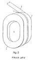
FIGURE 2 shows a standard earmuff containing a cushion according to prior art. -
FIGURE 3 shows a flow chart of a molding process for making hearing protectors according to the present invention. -
FIGURES 4 and5 show comparisons of REAT, IL, and calculated attenuation for earmuffs according to prior art. -
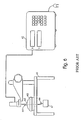
FIGURE 6 shows a static deflection measuring apparatus. -
FIGURE 7 shows a transmissibility measuring apparatus. -
FIGURE 8 shows a transmissibility measuring system. -
FIGURE 9A shows a standard semi-aural device containing foam caps according to the present invention. -
FIGURE 9B is a cross-sectional view of the foam component shown inFIGURE 9A . -
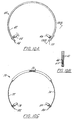
FIGURES 10A - C show alternative embodiments of standard semi-aural devices containing foam pods according to the present invention. -
FIGURES 10D -F show cross-sectional views of pods for the semi-aural devices according to the present invention. -
FIGURE 11 shows standard banded earplugs comprising foam earplugs according to the present invention. -
FIGURES 12A - D show alternative embodiments of foam earplugs according to the present invention. -
FIGURE 13 is a sectional view of an earplug with a stiffening member according to the present invention. -
FIGURE 14 is a sectional view of an alternative embodiment of an earplug having a stiffening member according to the present invention. -
FIGURE 15 shows attenuation of semi-aural hearing protectors of the prior art which enter the ear canal. -
FIGURE 16 shows attenuation of semi-aural protectors of the prior art which cap the ear. -
FIGURE 17 is a sectional view of a pod assembly having means for transmitting sound to the ear according to the present invention. -
FIGURE 18 is a sectional view of a pod assembly having a hollow stem for transmitting sound to the ear according to the present invention. -
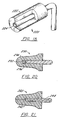
FIGURE 20 is a sectional view of earplug having a means for transmitting sound to the ear according to the present invention. -
FIGURE 21 is a sectional view of an earplug having a hollow stem for transmitting sound to the ear according to the present invention. - The critical component of the foam components which provide the improved attenuation in the hearing protective devices is its dynamic stiffness characteristics. The term "dynamically stiff' foam as used herein refers to a foam material having a low static stiffness and high dynamic stiffness, thereby providing improved attenuation for hearing protectors using the same. The degree of stiffness desired is dependent upon the ability of the cushion to form an acoustical seal against the ear part. It has been found that material with a low static stiffness, and high dynamic stiffness, provide improved attenuation according to the present invention.
- These stiffness characteristics are defined in terms of dynamic complex spring constant (K*), static spring constant (K,), and dynamic material loss factor (fl).
- In order to provide the improved attenuation according to the present invention it is important that the foam parts have a dynamic spring constant of at least about 4,4·104 N/m that are 300 pounds/inch and a dynamic material loss factor of at least about 0.25, as measured by the methods disclosed herein, and preferably a dynamic spring constant of at least about 14,6·104 N/m which are 1,000 pounds/inch. It is also important that the material has a static spring constant of up to about 8,8·103 N/m which are 60 pounds/inch, as measured by the methods disclosed herein, and preferably up to about 4,4·103 N/m which are 30 pounds/inch. Preferably, the foam has a density of about 84 kg/m3 to 336 kg/m3 corresponding to 5 - 20 pounds per cubic foot, and most preferably a density of about 117 kg/m3 to 252 kg/m3 corresponding to 7 - 15 pounds per cubic foot.
- While the foam components according to the present invention can be made of any polymeric material having the above described stiffness characteristics, polyurethane material has been found to be particularly suitable, for example, because of its stability in the presence of skin oils. And while any moldable polyurethane can be used, an especially preferred material is that described in
U.S. Patent No. 3,377,296 to Dwyer , the disclosure of which is herein incorporated by reference. - Polyurethane Formulations: The preferred polyurethane is diisocyanate based, preferably reacted with polyols with a portion thereof being at least tri-functional, and has an isocyanate index of less than about 0.9.
- According to Immergut and Mark (Plasticization and Plasticizer Processes, American Chemical Society Publications); "Plasticization, in general refers to a change in the thermal and mechanical properties of a given polymer which involves: (a) lowering of rigidity at room temperature; (b) lowering of temperature, at which substantial deformation can be effected with not too large forces; (c) increase of elongation to break at room temperature; (d) increase of the toughness (impact strength) down to the lowest temperature of serviceability. These effects can be achieved: (1) by compounding the given polymer with low molecular weight compound or with another polymer; and (2) by introducing into the original polymer a comonomer which reduces crystallizability and increases chain flexibility." Plasticizers have been categorized into two types, internal plasticizers and external plasticizers. Internal plasticizers are actually a part of the polymer molecule e.g., a second monomer is copolymerized into the polymer structure thereby making it less ordered, and therefore, more difficult for the chains to fit closely together. This softens the polymer - i.e., lowers the glass transition temperature (Tg) or the modulus.
- Usually, the internal plasticizer is a monomer whose polymer has good low temperature properties.
- External plasticizers are compounds mixed in with the polymer which make it more difficult for the chains to fit closely together. This softens the polymer - e.g., lowers the Tg or the modulus. External plasticizers are often categorized as primary or secondary, defining the degree of compatibility or in terms of its efficiency or permanence.
- Polyurethanes are typically block co-polymers consisting of polyester polyols and/or polyether polyols reacted with isocyanates having a functionality of 2 or more.
- Sometimes the term polymers of isocyanates is used to better define systems where water or amine terminated compounds are reacted resulting in polyureas. Here polyurethane will be used all-inclusively.
- When using a polymer polyol as a reactant, it is a plasticizer. Generally, the larger the polymer chain lengths for a particular type polyol the lower the Tg obtained.
- Types of polyols could also be referred to as having different efficiencies, with polyethers being more efficient than polyesters. Likewise, polyols could be considered more efficient than polyamines.
- Monofunctional reactants produce side chains which act as plasticizers.
- However, they may be more or less efficient than the plasticizer they replace. External plasticizer may be employed in polyurethane. Compatibility is quite important here and often a preferred approach has been to "under index" the system. The best way of ensuring compatibility is to use segments of the polymer itself as plasticizer.
- "Underindexing" is the in situ production of external plasticizer while at the same time producing more dangling polymer segments. Underindexing is not new to the art and was used in the early 1960s to produce soft foams for use in mattresses and the like. See, e.g.,
U.S. Patent No. 3,377,296 and Cellular Plastics - Today's Technology, April 24 - 25, 1963, "Technology of Super Soft Flexible Urethane Foams" by Dwyer, Kaplan, Pirer and Stone. - The cushions, pods, earplugs or other hearing protective foam components according to the present invention use di- and tri-functional polyether polyols of varying molecular weight, underindexing and density adjustments as methods of formulating compositions which produce molded, dynamically stiff; noise excluding earmuff cushions, and other hearing protective foam components. At least a portion of the polyol used should have trifunctionality (so as to produce a solid foam as opposed to simply a liquid polyurethane). Surfactant combinations are employed to maintain closed cells, a requirement for noise excluding foams. Surfactant/oil combinations may also be used, wherein the ratio of surfactant: oil is adjusted so as to aid in controlling cell strength and degree of reticulation. Preferably, the oil is a polysiloxane. An acrylic latex may be used to introduce a water blowing agent. Additional optional additives include, but are not limited to, catalysts, fillers, plasticizers, colorants, antifoam agents, fire retardants, cell stabilizers, cell regulators, chain extenders, hindered amine light stabilizers and internal mold release agents. Lowering of the isocyanate index (NCO/OH) results in softening, as does increasing polyol chain segment length.
- As shown in
FIGURE 2 , theprior art cushion 1 is attached to theseal plate 3, typically by a conventional pressure adhesive such as an acrylic material (not shown). The seal plate is similarly attached to the cup 4, again by conventional methods such as ultrasonic welding. Theheadband 5 is attached to the cup, by typical mechanical means such as through a grommet (not shown), e.g., like those used in the conventional E-A-R(g) 1000-3000 Model earmuffs produced by Cabot Safety Corporation, Indianapolis, Indiana. Thefoam liners 2 lining the inner surfaces of the cup 4 can be made of conventional open cell foam materials, such as conventional polyurethanes as are currently used. Elimination of the cushion bladder provides the advantages of material savings and labor savings, in addition to the increased attenuation. - It may also be preferred to mold the foam part inserts of the earmuff onto other components of the earmuff such as seal plates or seal plate components.
- Semi-Aural Hearing Protectors As used herein, "semi-aural hearing protector" refers generally to the entire class of semi-aural devices, including but not limited to hearing protectors that cap the entrance to the ear canal, protectors that enter the ear canal and seal the ear canal prior to the bend in the ear canal, and protectors that enter the ear canal and take the bend in the ear canal. Semi-aural hearing protectors can comprise a U-shaped flexible band and two pod assemblies for providing sound attenuation, as will be described in more detail below. A particularly preferred embodiment further comprises a stem or stiffener disposed within the foam component of each pod assembly. In an alternative embodiment, the foam component of each pod may further comprise a slippery outer surface for ease of insertion, for example a polyurethane coating. In yet another embodiment, the foam component of each pod may be embossed after molding.
- Referring now to
FIGURES 9A-B , a semi-aural hearing protector designed to cap the ear is shown generally at 20. Hearingprotector 20 has two dynamically stifffoam pod components chin band 30. In another embodiment of the present invention, it may be preferred to mold thefoam components band 30. In a preferred embodiment,foam components hemispherical portion 32 for contact with the ear, or any other shape suitable to optimize contact with the ear. A generallyconical back portion 34 forms aninternal recess 36 for receiving ends 26, 28 in snap-in fashion. As the size of theforward portion 32 of the dynamicallystiff foam component - Preferred embodiments of semi-aural devices of the present invention which enter the ear canal and seals the ear canal prior to the bend in the ear, or which enter the ear canal and go beyond the bend of the ear canal, are shown at
FIGURES 10A-F . - Referring to
FIGURE 10A and FIGURE 10B , an exemplary semi-aural device of thistype 40 includes aheadband 42 and a pair ofrotatable pods headband 42. As shown inFIGURE 10B , ends 48, 50 define a series of connected openings 51 wherebypods headband 42 for the wearer's comfort. -
FIGURE 10C depicts another embodiment of a semi-aural device of the present invention, comprisingheadband 70, which consists of arc-shapedparts pods parts -
Pods FIGURE 10D , whereinpods flange 62, and awider stem portion 64 andthird flange 66 for retention to headband 42 and adjustment along the headband through interconnected openings 51. In addition,flange 68 may aid in retention of the foam component. While the above-described means of pod attachment to the band are preferred, any suitable means well-known in the art may be used. For example,FIGURE 10F is a cross-sectional view of a pod attachable by snap-on means. - A slippery
outer coating 88 surrounds dynamicallystiff foam component 90 andstem 92. Attachment means 94 containsrecess 96 for retention on the end of a band comprising a larger generally hemispherical or conical portion such asportion 28 shown inFIGURE 9A . - An alternative embodiment of
pods FIG. 10E , wherein the dynamicallystiff foam component 150 is directly molded ontostem component 152. - The
tip 154 of thestem component 152 acts as a stiffener. The stiffener acts to pull foam into the ear to maximize attenuation. In order to fit all or most ear canals, the length of thefoam component 156 from about thetip 154 to the forward end of the pod inserted into the ear is preferably about 0,61 cm corresponding to 0.25 inches and the pod diameter at thestem tip 154 is preferably above about 1,12 cm corresponding to 0.46 inches. These dimensions will enable a comfortable fit even for those persons with difficult-to-fit ear canals (about one out ten users). - These dimensions are also suitable for use with various-shaped stiffeners, for example, the stiffener shown in
FIGURE 10D . In lieu of the above preferred foam dimensions, different sizes of pods may also be utilized to fit ear canals of different sizes. - For optimum attenuation performance of semi-aural devices having foam components, the preferred stiffening member is a stem having a tip of increased bendability. This increased bendability can be accomplished by a decrease in durometer of the stem or a decrease in the cross-sectioanl dimension of the stem. This increase in stem tip flexibility has been found to be a necessary requirement for the comfort of those wearers having fairly sharp bends in the ear canal. While the dynamically stiff foam of the present invention is suitable for use in semi-aural devices with a stiffener, other foams may also be used.
- Referring now to
FIGURES 17 and18 , yet another alternative embodiment of the semi-aural devices of the present invention is shown, wherein sound may be received by the wearer. InFIGURE 17 ,pod 210 is coaxially bored to form anopening 212 through the length oftip 214. Sound from atransceiver 216 may then be received by the wearer throughlongitudinal bore 212. Alternatively, as shown inFIGURE 18 ,foam component 222 of pod 220 is coaxially bored throughout its length. Theend 224 of a hollow headband is inserted therein. The headband is part of a headphone for conducting sound to the wearer through the longitudinal bore of the headband. - Referring now to
FIGURE 11 , a preferred semi-aural hearing protector of the present invention is shown wherein the foam component enters the ear canal past the bend in the ear canal.Foam earplug components chin band 94 at hemispherical ends 96, 98 through snap-on means. In another preferred embodiment of the present invention, it may be preferred to mold the foam part of the earplug directly onto theends 96, 98 ofband 94. - Earplugs Referring now to
FIGURES 12A-D , typical earplugs of the present invention are shown. Earplug shapes are well known in the art. One shape is a cylindricalfoam hearing protector 100 as shown inFIGURE 12A . Such an earplug may also comprise a stiffening member or stem 102 as shown inFIGURE 12C . A particularly preferred embodiment is the cylindrical shape 120 with flaredend 122 as shown inFIGURE 12B . This earplug may also contain a stiffening member or stem 124 as shown inFIGURE 12D . In one embodiment of the present invention, it may be preferred to mold the foam part of the earplug directly onto the stem or other stiffening members. - The foam ahead of the stem at the forward tip of the earplug is preferably about 0,61 cm corresponding to 0.25 inches and the earplug diameter at the stem tip is preferably about 1,12 cm corresponding to 0.46 inches or larger. In lieu of the above preferred foam dimensions, different sizes of earplugs may also be utilized to fit ear canals of different sizes. As with semi-aural hearing protectors, the preferred stiffening member is a stem having a tip of increased bendability. This increased bendability can be accomplished by a decrease in durometer or a decrease in the cross-sectional dimension of the stem. This increase in stem tip flexibility has been found to be a necessary requirement for the comfort of those wearers having fairly sharp bends in the ear canal.
- Other preferred embodiments include a slippery outer surface on the earplug, thereby aiding the earplug device to slide by the ear canal, and an embossed surface on the earplug.
- Referring now to FIGURES 19 and
20 , yet another alternative embodiment of the earplugs of the present invention is shown, wherein sound may be received by the wearer. In FIGURE 19,earplug 230 is coaxially bored to form anopening 232 through the length oftip 234. Sound from atransceiver 236 may then be received by the wearer throughlongitudinal bore 232. Alternatively, as shown inFIGURE 20 ,earplug 240 is coaxially bored through its length. Theend 242 of ahollow stem 244 is inserted therein.Hollow stem 244 may be attached to wire or headphone means for transmitting sound to the wearer through the bore of thehollow stem 244. - The method for making the cushions and earplugs according to the present invention can be described by reference to
FIGURE 3 . The reactants listed in Table 1 are mixed in conventional mixing equipment. This foam reaction mixture can be premixed and introduced into the mold or mixed as separate reactant streams and injected as a single stream directly into the mold, which may be preheated. "Injection" as used herein refers to mixing and introduction, or laying down of a stream under a given line pressure. For example, in a conventional mix/meter molding apparatus, at least two streams are mixed, and then introduced into the preheated mold, causing foaming to take place. Preferably, the contact mold surface is polypropylene, a copolymer of polypropylene or a mixture thereof. The injection can take place at low or high line pressures ranging from, for example, about 138 kPa to about 2070 kPa corresponding to 20 to about 300 pounds per square inch. A liner or other hearing protector device component may be placed in the mold before injection in order to mold the foam component directly thereto. - The temperature is allowed to remain sufficiently high to cure the foam in the shape of the cushion or earplug, and then the molded article is removed from the mold.
- Preferably, the mold release agent consists of an oil-wax mixture dissolved or suspended in a suitable medium. Alternatively, the foam may be molded to a hearing protector component or a pressure-sensitive adhesive component for ease of mold removal and/or lower costs of production. In still another embodiment, an in-mold coating is employed in place of a mold release agent. This coating may also serve to make the component more slippery, thereby aiding the device to slide by the ear canal.
- The foam component may be encapsulated or further coated if desired, or embossed. The foam component may also be crushed to rupture some of the closed cells to allow at least some air flow. Crushing may prevent puckering, or softens the foam to allow ease of compression. It may then be either glued or otherwise affixed to a seal plate or stem.
- As shown in
FIGURE 3 the reactants are first mixed (A), the mixture is introduced into the mold (B), the mixture is caused to foam (C), and the foam is cured (D), and the molded foam is next removed from the mold (E), and the molded foam is then optionally crushed (F). - The present invention is further illustrated by the following non-limiting examples.
- Example 22 A semi-aural pod similar to that shown in
FIG. 14 was formed by mixing the polyol formulation according to the Table below with isocyanate (HYPOL 2000) in a 1: 1 ratio in a mix/meter machine, and introducing the mixture into molds having cavities of the desired shape which were oversize by 12% in each dimension to allow for shrinkage. Mold tops containing stems were placed on the molds such that the final foam would be placed forward of the stem. and the molds clamped shut. After seven minutes, the molds were opened, and pods were dried. Average physical properties of the pods are listed in the Table below:Ingredients Part by Weight UCAR 154 2500 20% Pluronic F-68 138 Pluronic 25R2 3.3 Superfine/Superfloss 164 Sun Yellow YFD 1123 33 Water 421 Physical Properties, units Weight, g 0.445 Total length, inches (mm) 1.252 (31.80) Foam length, inches (mm) 0.818 (20.78) Stem Length 1.009 (25.63) Outer Stem Diameter 0.180 (4.57) Inner Stem Diameter 0.125 (3.18) Foam Weight, g 0.331 Maximum Foam Diameter, inch (mm) 0.635 (16.13) Foam Diameter 0.500 Inches from Tip, inches (mm) 0.429 (10.90) Foam Diameter 0.600 inches from Tip, inches (mm) 0.471 (11.96) Foam Forward of Stem, inches 0.243 (6.17) - Example 24: Another semi-aural pod for testing were formed by mixing the 32.94 parts by weight of the polyol formulation according to the Table below with 16.51 parts by weight isocyanate (Isonate 143L), thus achieving a ratio of 1.995. The mixture was poured onto molds (preheated to 50 "C) having cavities of the desired shape. Mold tops containing stems were placed on the molds such that the final foam would be placed forward of the stem and the molds clamped shut. After ten minutes, the molds were opened, and the foam pods were removed. The pods were post-cured at 55 "C for two hours. Physical properties of the pods arc listed in the Table below: EMI29.1
Ingredients Part by Weight Arcol LHT 240 56.0 Arcol PPG 425 12.0 Arcol LG 56 12.0 1,4-Butanediol 1.5 Tinuvin 765 0.60 Dabco T-12 0.100 Dabco BL-1 0.050 Y 4347 5.568 L-45 2.225 Water 0.900 Sun Yellow YFD 1123 1.385 Physical Properties, units Weight of Pod, g 0.608 Average Weight of Stem, g 0.115 Weight of foam, g 0.493 Volume of Foam, in3(mm3) 0.1779 (2.91) Density of foam, lbs/ft3 (g/mm3) 1.15 (0.0395) - The following tests were performed on the foams making up the foam components of the present invention. Because it may be difficult to test foam pods and earplugs for dynamic spring constant, especially if they have stems, the majority of tests were run on foams tested as earmuff cushions according to the procedure described in
U.S. Patent No. 5,420,381 to Gardner and Simon . When tested according to these methods, preferred hearing protector components have a static spring constant of up to about 8,8·103 N/m corresponding to 60 pounds per inch, and the most preferred hearing protector components have a static spring constant of up to about 4,4·103 N/m which are 30 pounds per inch. The preferred hearing protector components also have a dynamic spring constant of at least about 4,4·104 N/m which are 300 pounds per inch, and most preferably up to about 14,6·104 N/m corresponding to 1000 pounds per inch. - 1. Attenuation Testing and Insertion Loss Testing Attenuation testing and Insertion Loss (IL) testing are conducted in accordance with ASA STD 1 - 1975 (ANSI S3. 19), "Method for the Measurement of Real-Ear Protection of Hearing Protectors and Physical Attenuation of Earmuffs". The artificial flesh supplied for the physical method did not meet the Shore 00 durometer requirement of 20 + 5 stated in the above procedure. Therefore, an artificial flesh made of silicone rubber was made having a measured Shore durometer of 20, being 9,78 mm (= 0.385 inch) thick and having a Knowles Electronic pinna over the microphone center. The pinna was obtained from Industrial Research Products, Inc., a Knowles Company.
Insertion Loss testing employs an artificial test fixture (ATF) having artificial flesh yielding insertion loss results for earmuffs which are similar to those attained using real ear testing at threshold (REAT). When using the ATF it should be remembered that attenuation results for better earmuffs are usually bone conduction limited to 35 dB + about 2 at 2000 Hz.
The EPA has selected the NRR as a measure of hearing protector's noise reducing capabilities. The range of noise reduction ratings for existing hearing protectors is approximately 0 to 30.
When estimating NRR from IL test results, we used 10 dB and 20 dB for minimum 125 Hz insertion loss values for the E-A-RB Model 1000 and Model 3000 earmuffs respectively. These values were only required for the normal earmuffs as earmuffs utilizing dynamically stiff cushion yield higher values. Standard deviations of 3.0 are employed in calculating estimated NRRs. This value is typical of measured values.
Insertion Loss measurements are only used in lieu of REAT measurements.
FIGURES 4 and5 show comparisons of REAT, IL and calculated attenuation for conventional Model 3000 andModel 1000 Earmuffs respectively. These FIGURES are used as a basis for using IL in lieu of REAT for the purpose of evaluating dynamically stiff cushions.
InFIGURES 4 and5 , C is the calculated value, T is the result of 10 subject tests, N is the nominal limit due to bone conduction and I is the insertion loss. The calculated attenuation obtained by determining the frequency at 0 dB Attenuation (Fo) using the expression: F02 = A2/VM X 35460 Where: A = Area bounded by the cushion outer edge (cm2) V = Volume (cm3) M = Mass (g) InFIGURE 5 the increase in attenuation with frequency is applied using a 12 dB/octave. - 2. Static Deflectlon Testing: Static deflection is measured on an apparatus shown in
FIGURE 6 . The apparatus consists of a platform 61 with an attached adjustableelectronic thickness gauge 62. Theearmuff cup 63 has ahole 64 at the center of the top. At the top of the hole is aflat plate 65 with attachedhook 66 which protrudes through a hole in the platform so as to receive a 12.5Newton weight 67.
The earmuff cup with cushion in position is placed under the electronic thickness gauge and the gauge is zeroed. Simultaneously with adding a 12.5 Newton weight to the hook a stopwatch is started. After I 10 minutes the deflection is read from the electronic thickness gauge and recorded.
In these experiments the earmuff cup employed is from an E-A-Rt)Model 1000 Earmuff. The plate cup and hook weighed 90 grams exclusive of the cushion. - 3. Transmissibilltv Testing Transmissibility measurements are taken using the fixture shown in
FIGURE 7 and the equipment shown in the block diagram inFIGURE 8 .
For this work it was shown that adding weight to the cup to a total weight of 1.00 pound (454 grams) using barium sulfate filled epoxy resin was necessary to ensure adequate contact of the cushion to the platform. This total weight of 1.00 pound was employed during all tests.
Also, adequate stiffness of all connections and of the platform itself must be assured so as to give a straight line output free of secondary resonances to at least 1000 Hz. The platform used in this work was 5.0 inch (12.7 cm) in diameter, and 1.50 inch (3.81 cm) thick brass.
The test procedure used (with reference toFIGURES 7 and8 ) was as follows: Place theearmuff cup 71 with attached cushion and mass on top of theshaker platform 72.Shaker 73 and stand 74 support the platform. With an input level of 0.2 G (acceleration of gravity, 32 feet/second/second) obtain a transmissibility curve having the cursor at the natural frequency. Read and record the natural frequency Fn in Hz and the amplification A in dB. InFIGURE 8 theaccelerometer 81 is connected through thelow noise cable 82 to the power/amplifier unit 83. The power/amplifier unit is connected to thesignal output analyzer 86 which is connected to theaudio amplifier 87 and shaker and stand 88. Theaccelerometer 84 is connected to the microphone preamplifier andaccelerometer adapter 85 which is also connected to the signal output analyzer. The signal output analyzer is connected to the graphicsrecorder application package 89. The components are all commercially available, e.g., theaccelerometer 81 is a PCB 303A02; the low noise cable is PCB Model PCB 002C05; the power/amplifier 83 is PCB model 40DO6; thelow noise cable 82 can also be a PCB 003810; thesignal output analyzer 86 is a Bruel and Kjaer Model 30282FFT; the audio amplifier 87 a Proton model D540; the shaker and stand 88 are MB Electronics Model Err500; theaccelerometer 84 is Bruel and Kjaer Model 4693; the microphone preamplifier andaccelerometer adapter 85 are Bruel and Kjaer Model 2619 and W/JJ2615 respectively; thegraphics recorder 89 and application package are Bruel and Kjaer Model 2313 and W/827006 respectively. The cables are all standard commercially available low noise cables as described above. - 5. Noise Reduction Rating (NRR)
The Noise Reduction Rating (NRR), a variant of the NIOSH Rc factor, is the current EPA-proposed single number descriptor. The NRR is fully defined in EPA (1979) Noise Labeling Requirementsfor Hearing Protectors, Federal Register, Vol. 42, No. 190, 40 C.F.R. Part 211, 56139-56147. A sample NRR calculation is shown in Table 3. The key point to consider is that the NRR is subtracted from the measured (unprotected) C-weighted sound level to yield an effective A-weighted sound exposure for the employee. The idea of subtracting a noise reduction factor from a C-weighted sound level to find an A-weighted exposure was first proposed by Botsford in 1973.
This "C-A concept" is the important common ingredient in all of the successful single number descriptors proposed in recent years. As can be seen in Table 3, the NRR is the difference between the overall C-weighted sound level of a pink (flat by octaves) noise spectrum and resulting A-weighted noise levels under the protector. The attenuation values used in the calculation are the measured laboratory attenuation values minus two standard deviations. This correction assures that the attenuation values used in the calculation procedure are actually realizable by the majority of employees who conscientiously and correctly wear their protectors. This correction will not account for employee misuse or abuse of the protectors. - In addition attenuation tests were performed for foam pod components of semi-aural hearing protectors according to Examples 23 and 24. In particular, attenuation tests were performed for foam pod components of semi-aural hearing protectors, of the type which enters the ear canal and seals the ear canal prior to the bend. It was noticed that occasional subjects have difficulty fitting earplugs and semi-aural devices. It was believed that earplugs or semi-aural devices that fit such subjects, yielding good attenuation, would be superior hearing protective devices capable of protecting a greater range of potential users. Thus, a particular individual, Fields, was selected for testing based on his difficulty in fitting push-in earplugs and semi-aural devices.
- To explain why Fields was difficult to fit, anthropometric measurements of thirty subject's ear canals were made, form ear molds of the subjects' ear canals. Fields' left ear canal measured only 0.187 inches (4.75 mm) at its narrowest point prior to the bend in the ear canal. The width when measured at the point where the ear canal was the narrowest measured 0.447 inches (11.35 mm), thus yielding an aspect ratio of 2.39.
- These dimensions probably explain why Fields is difficult to fit with earplugs or semiaural devices.
- The foam pod components were therefore tested for attenuation in accordance with ANSI S3.19 with Fields as the only subject. The foam pods were attached to the neckband of
FIG. 9A , suing a short section of vinyl tubing so as to allow ease of rotation of the tubing about theballs 36 at each end ofneckband 30. The results are shown in the Table below:Example 23 Example 24 Attenuation As Received With Pond's Cold Cream As Received 125 Hz 30.7 36.3 35.3 250 Hz 25.3 31.0 33.7 500 Hz 19.3 33.3 38.0 1000 Hz 22.7 36.3 39.7 2000 Hz 28.3 31.3 34.0 3150 Hz 40.3 39.0 43.0 4000 Hz 40.3 39.0 40.7 6300 Hz 43.3 49.0 44.7 8000 Hz 43.3 49.0 44.7 NRR, dB 18.9 27.3 27.7 Comfort 3 3 3 - As shown in the above Table, a slippery surface (in this test produced by the application of Pond's cold cream) aids insertion, allowing much improved attenuation.
- Furthermore, the stem, which functions as a stiffener, allows the fabrication of semiaural devices yielding attenuation on a difficult-to-fit subject exceeding reported attenuations of all other semi-aural devices shown in
FIGS 15 and16 . Finally, Example 24, which has pods of dynamically stiff foam without a slippery surface, yields even higher low frequency attenuation results. Here again, the stem, acting a stiffener, is an important element of the semi-aural device. - In addition to increased attenuation, the semi-aural device components and earplugs of the present invention provide improved ease of manufacture. Many earmuff cushions have been made and tested, most of which gave superior low frequency insertion loss and estimated NRRs. REAT and IL values as well as NRRs calculated from them checked each other very well although if questions should arise REAT ANSI S3.19 values could be utilized as a reference. All foam cushions produced of molded polyurethane on foam machinery have an ease of manufacturing advantage (which would also show itself as a low cost manufacturing advantage). Cushions having static defections of about 1,27 mm (= 0.05 inch) or greater are preferred for problem subjects with a static deflection of about 0.10 or more being more preferred. Cushions having an Fn as tested in this report of about 52 Hz or more show equal to or superior performance to normal cushions. Cushion which deflect to a thickness of about 12,7 mm (= 0.5 inch) or less when compressed (as measured by the static deflection test) are preferred. Cushions with increased contact with the head are preferred.
- Applied coatings, especially in-mold coatings, may be advantageous. Placing molded dynamically stiff cushions into current art bladders may also yield increased performance but at higher cost. The total effect of amplification at resonance (A) is not totally understood at this time. It is felt that cushions having Fn about 52 Hz or less may be useable as low cost cushions of similar performance to the prior art. However, more highly resilient cushions having Fn of about 52 Hz or less with A of 9.5 dB or more may yield inferior attenuation.
- From the above, it can be seen that as tested, the cushions of the present invention results in at least a 3 to 4 dB increase in attenuation over that obtainable with a conventional cushion. The dynamically stiff foam and method of manufacture of the present invention are also expected to provide improved components for various semi-aural devices, as well as for earplugs and other hearing protective devices.
Claims (18)
- A semi-aural hearing protector comprising a pair of pods comprising a dynamically stiff foam component for contact with the ear of the wearer, wherein:the foam component has a low static stiffness and a high dynamic stiffness,resulting in the semi-aural device having higher sound attenuation; andthe foam component has a dynamic spring constant of at least 4,4·104 N/m (300 pounds per inch) and a dynamic loss factor of at least 0.25.
- The semi-aural hearing protector of Claim 1, wherein the foam component has a dynamic spring constant of at least 14,6·104 N/m (1,000 pounds per inch).
- The semi-aural hearing protector of Claim 1, wherein the foam component has a static spring constant of up to 8,8•103 N/m (60 pounds per inch).
- The semi-aural hearing protector of Claim 1, wherein the foam component has a static spring constant of up to 4,4•103 N/m (30 pounds per inch).
- The semi-aural hearing protector of Claim 1, wherein the foam component comprises a polyurethane.
- The semi-aural hearing protector of Claim 5, wherein the polyurethane is the reaction product of a diisocyanate and a polyol component, the resulting polyurethane having an isocyanate index of less than 0.9.
- The semi-aural hearing protector of Claim 6, wherein the polyol component further comprises at least one additive selected from the group consisting of latex, oils, catalysts, fillers, plasticizers, colorants, antifoam agents, surfactants, fire retardants, cell stabilizers, cell regulators, chain extenders, hindered amine light stabilizers and internal mold release agents.
- The semi-aural hearing protector of Claim 7, wherein at least a portion of the polyol has a functionality of at least three.
- The semi-aural hearing protector of Claim 1, wherein the foam component further comprises a polyurethane coating.
- The semi-aural hearing protector of Claim 1, wherein the foam component is encapsulated.
- The semi-aural hearing protector of Claim 1, wherein the foam component further comprises an additional semi-aural hearing protector component molded thereto.
- The semi-aural hearing protector of Claim 1, further comprising a stiffener.
- The semi-aural hearing protector of Claim 12, wherein the tip of the stiffener has increased bendability.
- The semi-aural hearing protector of Claim 12, wherein the part of the foam component ahead of the stiffener at the forward part of the pod is at least 0.635 cm (0.25 inches) long and the cross-section of the foam component at the tip of the stiffener is at least 1.17 cm (0.46 inches) in diameter.
- The semi-aural hearing protector of Claim 1 having a substantially longitudinal bore through the foam component, said bore being adapted to receive the tip portion of a sound conducting tube.
- The semi-aural hearing protector of Claim 1, further comprising a transceiver embedded in the foam component, and having a substantially longitudinal bore from the tip of the foam component to the transceiver, said bore being adapted to transmit sound from the transceiver to the wearer.
- The semi-aural hearing protector of claim 1, wherein, the pods comprising a stiffener at least partially disposed within the foam component.
- The semi-aural hearing protector of any of Claims 1 to 17, wherein the pair of pods is fastened to opposite ends of a generally U-shaped connecting band.
Applications Claiming Priority (3)
| Application Number | Priority Date | Filing Date | Title |
|---|---|---|---|
| US698404 | 1996-08-15 | ||
| US08/698,404 US5792998A (en) | 1993-04-19 | 1996-08-15 | Acoustical hearing protective devices utilizing dynamically stiff foam and methods of producing same |
| PCT/US1997/013959 WO1998007296A1 (en) | 1996-08-15 | 1997-08-12 | Acoustical hearing protective devices utilizing dynamically stiff foam and methods of producing same |
Publications (3)
| Publication Number | Publication Date |
|---|---|
| EP0861571A1 EP0861571A1 (en) | 1998-09-02 |
| EP0861571A4 EP0861571A4 (en) | 2006-08-16 |
| EP0861571B1 true EP0861571B1 (en) | 2013-04-03 |
Family
ID=24805095
Family Applications (1)
| Application Number | Title | Priority Date | Filing Date |
|---|---|---|---|
| EP97937161A Expired - Lifetime EP0861571B1 (en) | 1996-08-15 | 1997-08-12 | Acoustical hearing protective devices utilizing dynamically stiff foam and methods of producing same |
Country Status (6)
| Country | Link |
|---|---|
| US (1) | US5792998A (en) |
| EP (1) | EP0861571B1 (en) |
| JP (1) | JPH11514559A (en) |
| AU (1) | AU718846B2 (en) |
| WO (1) | WO1998007296A1 (en) |
| ZA (1) | ZA977347B (en) |
Cited By (1)
| Publication number | Priority date | Publication date | Assignee | Title |
|---|---|---|---|---|
| WO2022189267A1 (en) | 2021-03-11 | 2022-09-15 | Universitätsspital Basel | Osteosynthesis plate suitable as replacement of a synarthrosis |
Families Citing this family (70)
| Publication number | Priority date | Publication date | Assignee | Title |
|---|---|---|---|---|
| US6176576B1 (en) | 1997-06-06 | 2001-01-23 | Radians, Inc. | Eyewear supported by a wearer's concha of an ear |
| US5824966A (en) * | 1997-10-22 | 1998-10-20 | Bacou Usa Safety, Inc. | Enhanced band earplug |
| USD426880S (en) * | 1998-05-04 | 2000-06-20 | Howard Leight Industries | Twisted band for earplug |
| US6006857A (en) * | 1998-05-08 | 1999-12-28 | Howard Leight Industries | Earplug with insertion stem |
| NO307540B1 (en) | 1998-07-24 | 2000-04-17 | Meditron As | Headphone |
| US6920956B1 (en) | 1999-01-07 | 2005-07-26 | Cabot Safety Intermediate Corporation | Detectable earplug and method of manufacture thereof |
| WO2000054712A1 (en) * | 1999-03-16 | 2000-09-21 | Cabot Safety Intermediate Corporation | Hearing protective device |
| USD426845S (en) * | 1999-05-03 | 2000-06-20 | Radians, Inc. | Eyewear |
| US6129175A (en) * | 1999-05-07 | 2000-10-10 | Radians, Inc. | Acoustical control plastisol earpieces |
| US6095146A (en) * | 1999-07-20 | 2000-08-01 | Aearo Company | Glow-in-the-dark hearing protective devices |
| USD430673S (en) * | 1999-07-30 | 2000-09-05 | Teledyne Industries, Inc. | Ear piece |
| US6105715A (en) * | 1999-11-05 | 2000-08-22 | Aearo Company | Multi-color variably attenuating earplug |
| US6695093B1 (en) * | 2000-01-13 | 2004-02-24 | Aearo Company | Earplug |
| USD435058S (en) * | 2000-04-04 | 2000-12-12 | Radians, Inc. | Eyewear |
| CA2391776A1 (en) | 2000-05-31 | 2001-12-06 | Cabot Safety Intermediate Corporation | Process for applying a decorative pattern to earplugs |
| US6408981B1 (en) | 2000-09-27 | 2002-06-25 | Saint-Gobain Performance Plastics Corporation | Extruded monolithic foam earplug |
| EP1192920A1 (en) | 2000-09-29 | 2002-04-03 | The Procter & Gamble Company | Comfortable foam-based ear plugs |
| US20020124851A1 (en) * | 2000-11-28 | 2002-09-12 | Richard Knauer | Hearing protective device and method of making same |
| US6622816B2 (en) | 2001-04-24 | 2003-09-23 | Cabot Safety Intermediate Corp. | Personal protective devices having an energy activated material |
| US20030059071A1 (en) * | 2001-09-24 | 2003-03-27 | John Dunham | Personal audio device with hearing protection |
| US7141014B2 (en) | 2002-03-20 | 2006-11-28 | Siemens Hearing Instruments, Inc. | Cushioning device for use with a hearing aid |
| USD470479S1 (en) | 2002-05-13 | 2003-02-18 | Plantronics, Inc. | Headset headband |
| US20040045558A1 (en) * | 2002-09-06 | 2004-03-11 | Duncan Taylor | Earplug and method of manufacturing an earplug |
| US7370655B2 (en) | 2003-01-17 | 2008-05-13 | Cabot Safety Intermediate Corporation | Method of forming an earplug by laser ablation and an earplug formed thereby |
| US7305992B2 (en) * | 2003-02-25 | 2007-12-11 | Howard Leight Industries, Llc | Conforming earplug |
| US20050056288A1 (en) * | 2003-09-11 | 2005-03-17 | Walter Schreiber | Earplug and a method of forming an earplug |
| WO2005027776A2 (en) * | 2003-09-12 | 2005-03-31 | Howard Leight Industries, Llc | Earplug with bendable stiffener |
| US20050126845A1 (en) * | 2003-12-10 | 2005-06-16 | Vaudrey Michael A. | Attenuating foam insert and method for manufacture |
| US20080207790A1 (en) * | 2004-10-15 | 2008-08-28 | Knauer Richard E | Earplug |
| US7475686B2 (en) * | 2004-10-15 | 2009-01-13 | Cabot Safety Intermediate Corporation | Earplug |
| USD512982S1 (en) * | 2004-10-29 | 2005-12-20 | International Business Machines Corporation | Spherical headphones |
| US7220372B2 (en) * | 2004-12-01 | 2007-05-22 | Howard Leight Industries, Llc | Dual density earplug |
| US20080123884A1 (en) * | 2006-08-22 | 2008-05-29 | David Donenfeld | Passive hearing aid device |
| US8050444B2 (en) * | 2007-01-19 | 2011-11-01 | Dale Trenton Smith | Adjustable mechanism for improving headset comfort |
| US7984716B2 (en) | 2007-06-22 | 2011-07-26 | Kimberly-Clark Worldwide Inc. | Self-conforming sound attenuation earplug |
| DE102007042740A1 (en) * | 2007-09-07 | 2009-03-12 | Uvex Arbeitsschutz Gmbh | Earplugs |
| US20090277814A1 (en) * | 2008-05-09 | 2009-11-12 | 3M Innovative Properties Company | Securable earplug package |
| US20090277462A1 (en) * | 2008-05-09 | 2009-11-12 | 3M Innovative Properties Company | Foam earplug in deformable sheath |
| US8113207B2 (en) | 2008-08-22 | 2012-02-14 | Kimberly-Clark Worldwide, Inc. | Self-conforming sound attenuation earplug |
| USD596616S1 (en) | 2008-09-05 | 2009-07-21 | Apple Inc. | Earphone |
| KR20110105843A (en) * | 2008-12-23 | 2011-09-27 | 쓰리엠 이노베이티브 프로퍼티즈 컴파니 | Hearing protection methods and devices |
| WO2010075130A2 (en) | 2008-12-23 | 2010-07-01 | 3M Innovative Properties Company | Transportation vehicle sound insulation process and device |
| US10610413B2 (en) * | 2009-05-22 | 2020-04-07 | Honeywell Safety Products Usa, Inc. | Eartip |
| CN102596131B (en) * | 2009-06-03 | 2014-07-09 | 斯博瑞安听觉保护有限责任公司 | Non-Rubbing Foam Earpieces |
| JP5836941B2 (en) | 2009-06-25 | 2015-12-24 | スリーエム イノベイティブ プロパティズ カンパニー | Sonic barrier for audible acoustic frequency management |
| WO2011017453A1 (en) * | 2009-08-04 | 2011-02-10 | Hearing Components, Inc. | Foam compositions with enhanced sound attenuation |
| USD636484S1 (en) | 2009-10-22 | 2011-04-19 | Sperian Hearing Protection, Llc | Earplug |
| KR100974152B1 (en) * | 2010-03-15 | 2010-08-04 | 구자헌 | Non-adhensive anti-noise earplug and method for fabricating the same |
| US20110225705A1 (en) * | 2010-03-16 | 2011-09-22 | 3M Innovative Properties Company | Hearing protective device with moisture resistant earmuff sound absorbers |
| JP2012054780A (en) * | 2010-09-01 | 2012-03-15 | Sony Corp | Ear pad |
| US8413663B2 (en) | 2011-02-04 | 2013-04-09 | Moldex Metric, Inc. | Push-in type of earplug with improved insertion stem |
| AT511555B1 (en) * | 2011-04-11 | 2013-10-15 | Gunnar Mag Gruber | JEWELERY WITH HOLDER ELEMENTS FOR HUMAN HEARING AND INTEGRATED STORAGE |
| US8968613B2 (en) | 2012-07-12 | 2015-03-03 | 3M Innovative Properties Company | Method of making an earplug |
| US8679607B2 (en) | 2012-07-12 | 2014-03-25 | 3M Innovative Properties Company | Foamable article |
| US9737439B2 (en) | 2012-07-12 | 2017-08-22 | 3M Innovative Properties Company | Push-in earplug |
| US10881310B2 (en) | 2012-08-25 | 2021-01-05 | The Board Of Trustees Of The Leland Stanford Junior University | Motion artifact mitigation methods and devices for pulse photoplethysmography |
| USD718272S1 (en) * | 2013-09-09 | 2014-11-25 | Wr Nine Ventures Llc | Headphone headband |
| CA156547S (en) * | 2013-11-22 | 2015-03-09 | Lg Electronics Inc | Headset |
| USD805054S1 (en) * | 2015-12-30 | 2017-12-12 | Songying Liu | Wireless earphone for sports |
| USD817301S1 (en) | 2016-08-26 | 2018-05-08 | Apple Inc. | Headphones |
| US11173069B2 (en) | 2016-12-21 | 2021-11-16 | 3M Innovative Properties Company | Earplug with stem comprising a sleeve |
| USD845926S1 (en) | 2017-06-30 | 2019-04-16 | Apple Inc. | Earphones |
| USD842836S1 (en) * | 2017-07-17 | 2019-03-12 | Shaowu MA | Wireless headset |
| CN108896665A (en) * | 2018-08-27 | 2018-11-27 | 国网山东省电力公司电力科学研究院 | The applicability appraisal procedure of workplace noiseproof earplug |
| JP7421483B2 (en) * | 2019-02-18 | 2024-01-24 | 川本産業株式会社 | Earplugs and earplug manufacturing method |
| USD906297S1 (en) | 2019-09-13 | 2020-12-29 | Apple Inc. | Pair of earphones |
| USD980185S1 (en) | 2020-07-02 | 2023-03-07 | Apple Inc. | Earphones |
| USD1055030S1 (en) * | 2022-08-03 | 2024-12-24 | Panasonic Intellectual Property Management Co., Ltd. | Earphone |
| KR102789854B1 (en) * | 2022-09-08 | 2025-04-03 | 오렌슈츠 주식회사 | Industrial Anti-Noise Earplugs with Anti-Lost Function |
| USD983768S1 (en) * | 2022-10-08 | 2023-04-18 | Yingshan Wu | Earphone |
Family Cites Families (23)
| Publication number | Priority date | Publication date | Assignee | Title |
|---|---|---|---|---|
| US2801423A (en) * | 1956-06-05 | 1957-08-06 | Ca Nat Research Council | Ear defender |
| US3016054A (en) * | 1959-09-16 | 1962-01-09 | Maurice C Rosenblatt | Device for protecting ears from high intensity noise |
| NL291419A (en) * | 1962-04-13 | |||
| US3811437A (en) * | 1971-10-26 | 1974-05-21 | Cabot Corp | Earplugs |
| US4260575A (en) * | 1979-11-05 | 1981-04-07 | Koss Corporation | Method for molding ear cushions |
| US4461290A (en) * | 1980-09-08 | 1984-07-24 | Cabot Corporation | Hearing protectors |
| US4490857A (en) * | 1982-10-12 | 1985-01-01 | Leight Howard S | Band earplug |
| JPS59149919A (en) * | 1983-02-17 | 1984-08-28 | Toray Silicone Co Ltd | Production of reaction injection molding product |
| US4465159A (en) * | 1983-03-11 | 1984-08-14 | Cabot Corporation | Nonlinear ear protecting device |
| US4471496A (en) * | 1983-06-27 | 1984-09-18 | Cabot Corporation | Articulated earmuff-to-headband attachment construction |
| SE449949B (en) * | 1984-11-29 | 1987-06-01 | Bilsom Ab | EARNESS CONNECTION DEVICE INCLUDING TWO EARNESS CONNECTORS AND AN ELASTIC BOARD |
| US4682374A (en) * | 1986-03-05 | 1987-07-28 | Joseph Geiser | Protective ear covering |
| US4864610A (en) * | 1987-02-27 | 1989-09-05 | Acs Communications, Inc. | Earpiece for a telephone headset |
| US4725627A (en) | 1987-03-16 | 1988-02-16 | Signastone Incorporated | Squeezable toy with dimensional memory |
| US4819624A (en) * | 1987-06-18 | 1989-04-11 | Leight Howard S | Banded earplug |
| DE3819940A1 (en) * | 1988-06-11 | 1989-12-14 | Bayer Ag | METHOD FOR PRODUCING POLYURETHANE SOFT BLOCK FOAMS |
| US4958697A (en) * | 1989-09-11 | 1990-09-25 | The United States Of America As Represented By The Secretary Of The Army | Anatomically shaped earseals for headsets |
| US5188123A (en) * | 1990-08-20 | 1993-02-23 | Cabot Safety Corporation | Hearing protective earplug having alternative modes of insertion |
| US5038412A (en) * | 1990-08-20 | 1991-08-13 | `Totes`, Incorporated | Headband with earmuffs |
| US5203352A (en) * | 1990-10-16 | 1993-04-20 | Cabot Safety Corporation | Polymeric foam earplug |
| US5148887A (en) * | 1991-04-01 | 1992-09-22 | Gentex Corporation | Earcup assembly incorporating mechanical active noise reduction |
| US5420381A (en) | 1993-04-19 | 1995-05-30 | Cabot Safety Corporation | Acoustical earmuff |
| TW344750B (en) * | 1994-06-16 | 1998-11-11 | Ici Plc | Process for preparing flexible foams |
-
1996
- 1996-08-15 US US08/698,404 patent/US5792998A/en not_active Expired - Lifetime
-
1997
- 1997-08-12 AU AU39739/97A patent/AU718846B2/en not_active Ceased
- 1997-08-12 JP JP10509882A patent/JPH11514559A/en active Pending
- 1997-08-12 EP EP97937161A patent/EP0861571B1/en not_active Expired - Lifetime
- 1997-08-12 WO PCT/US1997/013959 patent/WO1998007296A1/en not_active Ceased
- 1997-08-15 ZA ZA9707347A patent/ZA977347B/en unknown
Cited By (2)
| Publication number | Priority date | Publication date | Assignee | Title |
|---|---|---|---|---|
| WO2022189267A1 (en) | 2021-03-11 | 2022-09-15 | Universitätsspital Basel | Osteosynthesis plate suitable as replacement of a synarthrosis |
| US12491014B2 (en) | 2021-03-11 | 2025-12-09 | Universitätsspital Basel | Osteosynthesis plate suitable as a replacement of a synarthrosis |
Also Published As
| Publication number | Publication date |
|---|---|
| JPH11514559A (en) | 1999-12-14 |
| AU718846B2 (en) | 2000-04-20 |
| WO1998007296A1 (en) | 1998-02-19 |
| AU3973997A (en) | 1998-03-06 |
| US5792998A (en) | 1998-08-11 |
| EP0861571A4 (en) | 2006-08-16 |
| ZA977347B (en) | 1998-03-23 |
| EP0861571A1 (en) | 1998-09-02 |
Similar Documents
| Publication | Publication Date | Title |
|---|---|---|
| AU718846B2 (en) | Acoustical hearing protective devices utilizing dynamically stiff foam and methods of producing same | |
| EP0695315B1 (en) | Acoustical earmuff | |
| US9902127B2 (en) | Foam cushion for headphones | |
| USRE29487E (en) | Earplugs | |
| CA2229859A1 (en) | Acoustical earmuff with incorporated snap-in foam cushion | |
| US6129175A (en) | Acoustical control plastisol earpieces | |
| US10623846B2 (en) | Earpieces employing viscoelastic materials | |
| EP2547300B1 (en) | Hearing protective device with moisture resistant earmuff sound absorbers | |
| US11812244B2 (en) | Wearable devices using shape memory polymers | |
| EP0487716B1 (en) | Hearing protective earplug | |
| CA2234156C (en) | Acoustical hearing protective devices utilizing dynamically stiff foam and methods of producing same | |
| MXPA98002965A (en) | Acoustical hearing protective devices utilizing dynamically stiff foam and methods of producing same |
Legal Events
| Date | Code | Title | Description |
|---|---|---|---|
| PUAI | Public reference made under article 153(3) epc to a published international application that has entered the european phase |
Free format text: ORIGINAL CODE: 0009012 |
|
| 17P | Request for examination filed |
Effective date: 19980515 |
|
| AK | Designated contracting states |
Kind code of ref document: A1 Designated state(s): DE FR GB IT SE |
|
| A4 | Supplementary search report drawn up and despatched |
Effective date: 20060719 |
|
| 17Q | First examination report despatched |
Effective date: 20070504 |
|
| RAP1 | Party data changed (applicant data changed or rights of an application transferred) |
Owner name: 3M INNOVATIVE PROPERTIES COMPANY Owner name: CABOT SAFETY INTERMEDIATE LLC |
|
| RAP1 | Party data changed (applicant data changed or rights of an application transferred) |
Owner name: 3M INNOVATIVE PROPERTIES COMPANY |
|
| GRAP | Despatch of communication of intention to grant a patent |
Free format text: ORIGINAL CODE: EPIDOSNIGR1 |
|
| GRAS | Grant fee paid |
Free format text: ORIGINAL CODE: EPIDOSNIGR3 |
|
| GRAA | (expected) grant |
Free format text: ORIGINAL CODE: 0009210 |
|
| AK | Designated contracting states |
Kind code of ref document: B1 Designated state(s): DE FR GB IT SE |
|
| REG | Reference to a national code |
Ref country code: GB Ref legal event code: FG4D |
|
| REG | Reference to a national code |
Ref country code: DE Ref legal event code: R096 Ref document number: 69740575 Country of ref document: DE Effective date: 20130529 |
|
| REG | Reference to a national code |
Ref country code: SE Ref legal event code: TRGR |
|
| PLBE | No opposition filed within time limit |
Free format text: ORIGINAL CODE: 0009261 |
|
| STAA | Information on the status of an ep patent application or granted ep patent |
Free format text: STATUS: NO OPPOSITION FILED WITHIN TIME LIMIT |
|
| PG25 | Lapsed in a contracting state [announced via postgrant information from national office to epo] |
Ref country code: IT Free format text: LAPSE BECAUSE OF FAILURE TO SUBMIT A TRANSLATION OF THE DESCRIPTION OR TO PAY THE FEE WITHIN THE PRESCRIBED TIME-LIMIT Effective date: 20130403 |
|
| 26N | No opposition filed |
Effective date: 20140106 |
|
| REG | Reference to a national code |
Ref country code: DE Ref legal event code: R097 Ref document number: 69740575 Country of ref document: DE Effective date: 20140106 |
|
| PGFP | Annual fee paid to national office [announced via postgrant information from national office to epo] |
Ref country code: DE Payment date: 20140806 Year of fee payment: 18 |
|
| PGFP | Annual fee paid to national office [announced via postgrant information from national office to epo] |
Ref country code: FR Payment date: 20140808 Year of fee payment: 18 Ref country code: GB Payment date: 20140806 Year of fee payment: 18 Ref country code: SE Payment date: 20140826 Year of fee payment: 18 |
|
| REG | Reference to a national code |
Ref country code: DE Ref legal event code: R119 Ref document number: 69740575 Country of ref document: DE |
|
| REG | Reference to a national code |
Ref country code: SE Ref legal event code: EUG |
|
| GBPC | Gb: european patent ceased through non-payment of renewal fee |
Effective date: 20150812 |
|
| PG25 | Lapsed in a contracting state [announced via postgrant information from national office to epo] |
Ref country code: SE Free format text: LAPSE BECAUSE OF NON-PAYMENT OF DUE FEES Effective date: 20150813 |
|
| REG | Reference to a national code |
Ref country code: FR Ref legal event code: ST Effective date: 20160429 |
|
| PG25 | Lapsed in a contracting state [announced via postgrant information from national office to epo] |
Ref country code: GB Free format text: LAPSE BECAUSE OF NON-PAYMENT OF DUE FEES Effective date: 20150812 Ref country code: DE Free format text: LAPSE BECAUSE OF NON-PAYMENT OF DUE FEES Effective date: 20160301 |
|
| PG25 | Lapsed in a contracting state [announced via postgrant information from national office to epo] |
Ref country code: FR Free format text: LAPSE BECAUSE OF NON-PAYMENT OF DUE FEES Effective date: 20150831 |