EP4303971B1 - Verfahren und vorrichtung zum aushärten eines klebstoffs zwischen elektroden-lagen eines elektroden-stapels - Google Patents
Verfahren und vorrichtung zum aushärten eines klebstoffs zwischen elektroden-lagen eines elektroden-stapels Download PDFInfo
- Publication number
- EP4303971B1 EP4303971B1 EP23176723.7A EP23176723A EP4303971B1 EP 4303971 B1 EP4303971 B1 EP 4303971B1 EP 23176723 A EP23176723 A EP 23176723A EP 4303971 B1 EP4303971 B1 EP 4303971B1
- Authority
- EP
- European Patent Office
- Prior art keywords
- electrode stack
- transport device
- station
- stamp
- curing
- Prior art date
- Legal status (The legal status is an assumption and is not a legal conclusion. Google has not performed a legal analysis and makes no representation as to the accuracy of the status listed.)
- Active
Links
Images

Classifications
-
- H—ELECTRICITY
- H01—ELECTRIC ELEMENTS
- H01M—PROCESSES OR MEANS, e.g. BATTERIES, FOR THE DIRECT CONVERSION OF CHEMICAL ENERGY INTO ELECTRICAL ENERGY
- H01M8/00—Fuel cells; Manufacture thereof
- H01M8/02—Details
- H01M8/0297—Arrangements for joining electrodes, reservoir layers, heat exchange units or bipolar separators to each other
-
- H—ELECTRICITY
- H01—ELECTRIC ELEMENTS
- H01M—PROCESSES OR MEANS, e.g. BATTERIES, FOR THE DIRECT CONVERSION OF CHEMICAL ENERGY INTO ELECTRICAL ENERGY
- H01M8/00—Fuel cells; Manufacture thereof
- H01M8/10—Fuel cells with solid electrolytes
- H01M2008/1095—Fuel cells with polymeric electrolytes
Definitions
- the electrode stack can be used to produce a membrane electrode assembly, MEA.
- the MEA can comprise a gas diffusion layer, GDL, in particular an anode layer or a cathode layer in the form of a GDL.
- the MEA can also comprise a membrane, CCM, in particular a catalyst-coated membrane.
- the MEA can also have an adhesive that is applied in some areas, e.g. on one or all edges, between the electrode layers of the MEA. Details of this are defined in the claims; the description and the drawing also contain relevant information on the system and how it works, as well as on variants of the system.
- the quality of the installed membrane electrode arrangement/electrode stack is of great importance for the proper functioning of modern fuel cells, e.g. proton exchange membrane fuel cells.
- the process of bonding the multiple layers of the electrode stack and the subsequent curing must be carried out as gently as possible. Only the area of the electrode stack that corresponds to the adhesive surface between the layers of the electrode stack should be exposed to heat. On the other hand, the interior of the electrode stack is heated, which leads to high mechanical stress and can therefore impair the adhesive bonds. In the state of the art, this is solved by shielding the areas that are not to be heated from the areas that are to be heated. This is cumbersome and involves an increased time expenditure for the curing process.
- WO 2015/016974 A1 discloses the production and assembly of batteries with cooling properties for partially electric vehicles such as hybrid vehicles.
- the central unit for hot pressing consists of a rotating body or plate tool that can be partially heated or cooled.
- the document DE 10 2010 054 199 A1 discloses a method for producing a membrane electrode assembly for a fuel cell.
- the necessary components are as roll goods and/or as individual parts to a laminating unit in such a way that the components are continuously laminated.
- the document DE 10 2015 224 030 A1 discloses a hot-pressing device and a hot-pressing method of a membrane electrode assembly.
- the membrane electrode assembly is hot-pressed between hot plates.
- the entire plates are heated and the entire process of joining and hot-pressing is carried out discontinuously.
- a method and a device for connecting at least two components of a fuel cell are known.
- the adhesive used is applied to an area using a screen printing process and then irradiated.
- a method and a device for producing a membrane electrode arrangement are known.
- An adhesive coating is applied to a support frame.
- a first electrode is applied to the applied adhesive coating.
- the present invention only heats the region of an MEA/electrode stack that corresponds to an adhesive between the electrode layers of the electrode stack.
- the regions of the MEA/electrode stack that do not correspond to an adhesive between the electrode layers, i.e. the regions without adhesive, can be cooled.
- the electrode stack can be conveyed stress-free and continuously and cured during the process. During conveying, the electrode stack experiences little or no (tensile or clamping) forces.
- the stamp can be tempered in zones, meaning that only contact surfaces or areas between the stamp and the electrode stack that correspond to and/or are in contact with tempering zones of the stack are tempered. This reduces the mechanical stress on the adhesive bond and the electrodes as a whole during tempering and curing. There is no need for laborious shielding of electrode stack surface areas that are not to be tempered.
- the arrangement/removal of the stamp on/from the electrode stack can take place before the curing station, in particular upstream of the curing station, or during conveying through the curing station; or after the curing station, in particular downstream of the curing station.
- the curing station can have a curing station inlet and a curing station outlet.
- the transport device with the received electrode stack can be fed to the curing station through the curing station inlet, and the transport device with the heated/cured electrode stack can be conveyed out of the curing station through the curing station outlet.
- the curing of the picked-up electrode stack can begin while the transport device is being conveyed through the curing station, in particular at the moment the transport device is fed into the curing station.
- the curing can begin with the arrangement/placing of the stamp on the electrode stack or with the feeding of the electrode stack into the transport device.
- This device allows curing in a continuous conveying process. Furthermore, the stamp is heated in zones. This means that parts of the electrode stack surface can be heated and/or other parts of the electrode stack surface can be cooled. This reduces the mechanical stress on the adhesive bonds and on the areas of the electrode stack during curing. There is no need for laborious shielding of the areas of the electrode stack that are not to be heated/cured.
- the extent/dimension of the stamp surface can correspond to the extent/dimension of an electrode stack surface and/or the pallet. Furthermore, the extent/dimension of the stamp surface can be smaller than the extent/dimension of the pallet. Furthermore, the stamp, in particular the stamp surface, can have a stamp surface edge.
- the stamp surface can have raised and/or recessed stamp surface areas. The raised and/or recessed stamp surface areas can be designed such that the stamp surface edge is designed as a raised stamp surface area.
- the raised stamp surface area can correspond to an adhesive between the electrode layers of an electrode stack.
- the raised stamp surface area can correspond to the stamp heating zones.
- the recessed stamp surface areas can correspond to the stamp cooling zones.
- the dimension/extension of the stamp surface can be larger than the extent/dimension of the electrode stack.
- the raised stamp edge can surround/surround the electrode stack so that the stamp edge at least partially contacts at least one side surface of the electrode stack.
- the transport device can have an open and a closed state.
- the closed state can be characterized in that the stamp, in particular the stamp surface and/or the stamp heating zone, rests flat/plane-parallel/parallel/completely/over the entire surface of the received electrode stack and/or surrounds/encompasses it or presses the entire surface of the electrode stack against the pallet.
- the open state can be characterized in that the stamp, in particular the stamp surface and/or the stamp heating zone, does not rest flat/plane-parallel/parallel/completely/over the entire surface of the received electrode stack and/or does not surround/encompass it and/or does not press the entire surface of the electrode stack against the pallet.
- the transport device can assume an input state and/or output state.
- the input state and/or the output state can be defined in that the, in particular assigned, stamp assumes a positional state relative to the pallet and/or the electrode stack, so that the electrode stack can be removed/arranged vertically from/onto the pallet and/or transport device.
- the input and output states can be the same state.
- the input state/output state and/or the open/closed state can be achieved by means of a mechanical, in particular electromechanical, and/or pneumatic, in particular electropneumatic and/or hydraulic, in particular electrohydraulic and/or magnetic, in particular electromagnetic, state device.
- the state device can be assigned/assigned to the at least one stamp.
- the state device can be part of the transport device.
- the state device can be part of the curing station.
- the conveying device can be designed as a conveyor belt/transport belt.
- the conveying device can be designed as a roller conveyor or roller track, in particular as an all-round roller track.
- the conveying device can be designed as an air cushion table and/or air track table.
- the stamp is designed as part of the transport device and the device further comprises: a first heating station which is arranged along the conveyor device and which is intended and configured to heat the at least one transport device or the stamp or the stamp heating zone in order to heat the thermal contact surface when the stamp is pressed against the electrode stack.
- the curing process in the device begins with the placement of the stamp on the electrode stack, whereby the transport device and/or the stamp and/or the stamp heating zone can be heated in the first heating station.
- the The first heating station can be designed as a continuous heating station or continuous oven.
- the heating station can be arranged upstream of the curing station in relation to the conveying direction, in particular in front of the curing station entrance.
- the first heating station can be set up to heat the stamp in the stamp heating zone inductively or electrically.
- the transport device and/or the stamp and/or the stamp heating zone can be heated in the first heating station in the open or closed state and/or in the input/output state.
- the first heating station can have a heating station inlet and a heating station outlet.
- the transport device to be heated can be fed to the heating station through the heating station inlet, in particular along the conveyor path, and/or the transport device, in particular heated transport device, leaves the first heating station through the heating station outlet, in particular along the conveyor path.
- the tempering unit can be at least partially designed as a cooling unit and can be configured to cool the stamp cooling zone, wherein the cooling contact surface is cooled when the stamp is pressed.
- the electrode stack surface that does not correspond to an adhesive between the electrode layers of an electrode stack can be cooled. There is no need for cumbersome shielding of the electrode stack surface that does not correspond to an adhesive between the layers of an electrode stack.
- the zone-by-zone heating and cooling of the electrode stack means that the interior of the electrode stack is not subjected to as much stress, which means that the adhesive bond between the layers of the electrode stack is subjected to less/barely any stress.
- the stamp can be part of the curing station and/or the tempering device can be partially designed as a heating unit which is designed to heat the at least one stamp or the stamp heating zone.
- the curing station can further comprise a circulation unit on which the stamp is arranged and which can be configured to press the at least one stamp against the received electrode stack during the conveying of the transport device in order to heat the thermal contact surfaces and to cure the adhesive of the electrode stack received in the transport device.
- the tempering device can be designed as a heating and cooling unit and can be set up to heat the stamp heating zone and cool the stamp cooling zone.
- a heat contact surface and/or cooling contact surface can be created with the electrode stack.
- the input device and/or the output device can be designed as a vacuum belt, in particular an overhead vacuum belt.
- the electrode stacks can therefore be fed into and removed from the transport device without tension/with little tension using the input and output device.
- no output device is arranged along the conveyor path, but the transport device can be conveyed along the conveyor path to further processing stations and/or machining stations.
- the input device can be arranged between the first heating station and the curing station, or before the curing station or upstream of the curing station, in particular before the curing station entrance.
- the output station can be arranged after the curing station, in particular after the curing station exit.
- the input device can be arranged along the conveyor path between the heating station exit and the curing station entrance.
- the output station can be arranged between the heating station entrance and the curing station exit.
- the input and/or output device can be arranged on the same level as the conveyor device.
- the input and/or output device can be arranged on a higher level than the conveyor device.
- the input and/or output device can be arranged on a lower level than the conveyor device.
- the input station can be arranged between the first heating station and the curing station, or before the curing station or upstream of the curing station, in particular before the curing station entrance, and can be set up to feed the electrode stack to the transport device.
- the output station can be arranged after the curing station, in particular after the curing station exit, and can be set up to remove the electrode stack from the transport device.
- the input station can be arranged along the conveyor path between the heating station exit and the curing station entrance.
- the output station can be arranged between the heating station entrance and the curing station exit.
- the input and/or output station can be designed as an automatic pick-and-place machine or "pick-and-place robot".
- the automatic pick-and-place machine or "pick-and-place robot” can remove an electrode stack from the feed conveyor path and/or the transport device; and/or feed an electrode stack to the transport device and/or the removal conveyor path.
- the automatic pick-and-place machine or "pick-and-place robot” can be set up to put the transport device into an input and/or output state, and/or into a closed and/or open state.
- the tasks of the input and output station can be carried out by the same automatic pick-and-place machine or "pick-and-place robot".
- the transport device with the electrode stack is fed and the same is removed from the transport device in the input and/or output station.
- the input and output station can be designed as an automatic pick-and-place machine or "pick-and-place robot".
- the automatic pick-and-place machine can be arranged along the conveyor, in particular at the level and/or near the curing station and/or on the curing station, in order to feed the transport device and remove the electrode stack in the input and output station.
- the status device can be part of the automatic pick-and-place machine or the "pick-and-place robot".
- the supply and/or removal conveyor path can be arranged on the same level as the conveyor.
- the supply and/or removal conveyor path can be arranged on a higher level than the conveyor.
- the supply and/or removal conveyor path can be arranged on a lower level than the conveyor.
- the transport device can be fed again via the conveyor path of the receiving station or upstream of the receiving station, in particular the curing station entrance or the first heating station; or upstream of the first heating station, in particular the heating station entrance.
- a part of a stamp body that corresponds to the stamp heating zone or the stamp cooling zone can be made of different materials and/or material thicknesses.
- the part of the stamp body that corresponds to a stamp cooling zone can be made of non-conductive materials, in particular plastic, in particular heat-resistant plastics.
- the part of the stamp body that corresponds to the stamp heating zone can be made of conductive material.
- the part of the stamp body that corresponds to a stamp cooling zone may be made of a thinner material than the part of the stamp body that corresponds to a stamp heating zone.
- the stamp can be designed as a hold-down stamp and/or a heating stamp; and/or the stamp or the stamp heating zones can be heated with electrical current or inductively or via a heating station.
- Electrode stack manufacturing device comprising the device for curing the electrode stack and/or a transport device.
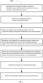
- Fig. 1 shows a flow chart for the method 200 for curing an adhesive between electrode layers of an electrode stack.
- a first step an electrode stack with several electrode layers is provided. At least one adhesive is arranged between the electrode layers.
- this electrode stack is picked up with a transport device.
- the transport device that has picked up the electrode stack is transported along a conveyor path to a curing station.
- a stamp presses the electrode stack against the pallet. The stamp is tempered zone by zone.
- the transport device that has picked up the electrode stack and presses it against the stamp is conveyed through the curing station and cures the adhesive between the electrode layers of the electrode stamp.
- the stamp is removed from the electrode stack. The electrode stack is then removed from the transport device.
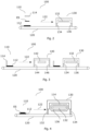
- Fig. 2 shows a device 100 which cures an adhesive between electrode layers of an electrode stack.
- the device comprises a transport device 110, a conveyor device 120 and a curing station 130.
- the transport device 110 which in the Fig. 2 shown as an exploded view, comprises: a pallet 112 and a stamp 114, between which a received electrode stack ES is arranged.
- the stamp is part of the transport device and is mounted on the pallet in a rotatable/swivel-able manner.
- the stamp surface of the stamp is flat and the stamp has at least one stamp cooling zone 114b (see Fig. 7 ) and at least one stamp heating zone 114a (see Fig. 7 ).
- the conveyor device is designed as a conveyor belt and conveys the transport device with the received electrode stack ES along the conveying direction 122.
- the curing station 130 is arranged along the conveyor device 120 and is set up to inductively heat the stamp heating zones.
- the curing station has a curing station inlet 134 and a curing station outlet 136.
- the transport device 110 is conveyed to the curing station inlet 134.
- the transport device 110 is located upstream of the curing station 130 in relation to the conveying direction 122.
- the transport device 110 is closed, whereby the transport device changes to a closed state. In the closed state, the received electrode stack ES forms a heat contact surface and a cooling contact surface with the stamp 114 resting on it over its entire surface.
- the transport device 110 is conveyed in the closed state into the curing station 130.
- the stamp heating zone is inductively heated by the tempering unit 132 and releases the heat gained mainly via the heat contact surface to the electrode stack surface, which corresponds to an adhesive between the electrode layers of the electrode stack ES.
- the stamp cooling zone is not cooled in this example, so that the cooling contact surface does not experience active cooling.
- the stamp heating zone is heated to a temperature of about 100°C. Under certain circumstances, parts of the cooling contact surfaces that border on the heat contact surfaces experience a marginal Heating. In the majority of cases, however, only the stamp heating zone that corresponds to an adhesive between the electrode layers of the electrode stack is heated. When the stamp heating zone is heated, curing begins in the curing station 130.
- the stamp heating zone is no longer inductively heated.
- the transport device is conveyed along the conveying path to further (not illustrated) processing or machining stations.
- the transport device can be conveyed to a removal station.
- the Fig. 3 outlines an example of a device 100 for curing an adhesive between the electrode layers of an electrode stack with a first heating station 140 and a curing station 130.
- the transport device has a pallet on which the stamp is pivotably/rotatably mounted.
- the transport device 110 is illustrated in an input state and/or open state.
- the transport device 110 in the input state and/or open state is conveyed along the conveying direction 122 to the first heating station 140.
- the heating station 140 is designed as a continuous furnace and is set up to heat the stamp heating zone while the transport device is conveyed through the heating station.
- the heating station has a heating station inlet 144 and a heating station outlet 146.
- the transport device 110 in the input state is conveyed into the heating station 140 through the heating station inlet 144.
- the transport device 110 leaves the first heating station 140 through the heating station exit 146.
- the transport device 110 is now located downstream of the heating station exit 146 and upstream of the curing station entrance 134 and is still in the input state.
- a stack of electrodes to be cured is fed to the transport device 110, in particular the pallet 112 (not shown).
- the transport device 110 is then closed by the stamp 114 flying over the entire surface of the electrode stack (not shown) and pressing it against the pallet. Since the stamp heating zone was heated in the continuous furnace 140 and now rests on the electrode stack ES, the heat contact surface heats up.
- the transport device 110 is conveyed on the conveyor device 120 along the conveying direction 122 to the curing station 130, wherein the transport device is fed to the curing station through the curing station inlet 134.
- the tempering unit 132 is partially designed as a cooling unit and is set up to cool the stamp cooling zone.
- the transport device 110 is conveyed out of the curing station 130 through the curing station outlet 136.
- the transport device can assume a removal state (not illustrated) in order to remove the electrode stack ES, or the transport device is conveyed along the conveying direction 122 to further processing and/or machining stations (not illustrated).
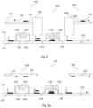
- the Fig. 4 shows an example of a device 100 for curing an adhesive between the electrode layers of an electrode stack with a curing station and a circulation unit 136 on which a plurality of stamps 114 are arranged.
- the tempering unit 132 is designed to heat the stamp heating zones, while the circulation unit 136 circulates the stamps in the curing station 130.
- An electrode stack ES is fed to the transport device 110 and the transport device is conveyed along the conveying direction 122 on the conveyor device 120 to the curing station 130.
- the transport device 110 is guided through the curing station entrance 132 into the curing station.
- the circulation unit 136 circulates the arranged stamps 114 at a circulation speed that corresponds to the conveying speed of the conveyor device 120.
- the stamp 114 detaches/separates from the electrode stack ES and is further circulated through the circulation unit 136 in the curing station 130.
- the transport device and the stamp are brought together and/or separated in the curing station.
- the Fig. 5 shows an example of a device 100 for curing an adhesive between the electrode layers of an electrode stack with a curing station 130, which further comprises an input device 150 and an output device 160. Both are arranged along the conveyor path 120 and are designed either to feed an electrode stack ES to the transport device 110 or to remove an electrode stack from the transport device.
- a transport device in the input/output state in particular the stamp heating surface, is heated in a first heating station 140.
- the heating station is designed as a continuous furnace and heats the stamp heating surface inductively.
- the transport device is conveyed out of the continuous furnace and is located between the heating station output 146 and the curing station input 132.
- the electrode stack ES is fed to the transport device via the input device with an adhesive to be cured.
- the electrode stack ES is fed via a feed conveyor path 152 along a feed conveyor direction 154 and via an input station 156 of the opened transport device 110.
- the transport device 110 then goes into the closed state. Since the stamp heating zone has been heated, the thermal contact surface heats up when the stamp is placed on the electrode stack.
- the transport device 110 is conveyed on the conveyor device 120 along the conveying direction 122 to the curing station 130, wherein the transport device is fed through the curing station entrance 134 of the curing station.
- the tempering unit 132 is designed as a cooling unit in this variant and is set up to cool the stamp cooling surface.
- the thermal contact surfaces are heated by the previously heated stamp heating zone; and the cooling contact surfaces are cooled by the curing station 130, wherein the thermal contact surface corresponds to an adhesive between the electrode layers of the electrode stack ES.
- the transport device 110 is conveyed through the curing station exit 136 from the curing station 130.
- the transport device 110 assumes the output state.
- the output device 160 in particular the output station 166, removes the electrode stack from the transport device and conveys it on a removal conveyor path 162 along a removal conveyor direction 164.
- the electrode stack ES is separated from the transport device 110.
- the transport device is fed again along the conveyor direction 121 upstream of the heating station 140. The previously described sequence of the Fig. 5 is repeated.
- the Fig. 5a shows a device in a modified form to Fig. 5
- the input device 150 and the output device 160 are designed as overhead vacuum belts.
- the input device conveys the electrode stack along an input direction 151 and feeds it to the transport device 110.
- the output device removes the hardened electrode stack and conveys it along an output direction.
- the input and output devices are sketched at a large distance from the conveyor device and the transport device for illustration purposes.
- both vacuum belts would be mounted near the conveyor device so that the vacuum belts can feed and remove/suck the electrode stack to the transport device without causing damage (to the electrode stack and the transport device).
- the Fig. 6 shows an example of a stamp 114 with a recessed stamp cooling zone and a highlighted stamp heating zone.
- the stamp 114 has a stamp cooling zone 114b and a stamp heating zone 114a.
- the stamp cooling zone 114b is shown by the dashed line that occupies a part of the stamp surface.
- the stamp heating zone 114a is shown by the solid line of the highlighted other part of the stamp surface (excluding the flanks of the stamp heating zone).
- the stamp heating zone corresponds to an adhesive KS between the electrode layers of an electrode stack ES.
- the stamp heating zone can be heated inductively or electrically.
- the stamp cooling zone can be actively cooled. When the stamp 114 presses the electrode stack against the pallet (not shown), it rests completely on the electrode stack. In another variant, only the stamp heating zone can rest on the electrode stack and heat the resulting heat contact surface. If provided, the stamp cooling zone cools the space between the stamp cooling zone and the electrode stack and thus the cooling contact surface without contact.
- the Fig. 7 shows an example of a stamp 114 in which the stamp surface is flat/plane.
- the stamp surface has a stamp heating zone 114a and a stamp cooling zone 114b.
- the stamp heating zone 114a corresponds to the adhesive KS between the electrode layers of an electrode stack.
- the Fig. 8 shows an example of a stamp in which the dimension/extension of the stamp 114 is larger than the dimension/extension of the electrode stack ES.
- the stamp cooling zone 114b is shown as a dashed line and the stamp heating zone 114a is shown as a dotted line.
- the stamp in particular the stamp heating zone, includes the electrode stack, whereby side surfaces of the electrode stack are heated.
Landscapes
- Life Sciences & Earth Sciences (AREA)
- Engineering & Computer Science (AREA)
- Manufacturing & Machinery (AREA)
- Sustainable Development (AREA)
- Sustainable Energy (AREA)
- Chemical & Material Sciences (AREA)
- Chemical Kinetics & Catalysis (AREA)
- Electrochemistry (AREA)
- General Chemical & Material Sciences (AREA)
- Fuel Cell (AREA)
Description
- Hier werden ein Verfahren und eine Vorrichtung zum Aushärten eines Klebstoffs zwischen Lagen eines Elektroden-Stapels beschrieben. Der Elektroden-Stapel kann zur Herstellung einer Membran-Elektroden-Anordnung, MEA, dienen. Die MEA kann eine Gasdiffusionsschicht, GDL, umfassen, insbesondere eine Anodenschicht oder eine Kathodenschicht in Form einer GDL. Weiter kann die MEA eine, insbesondere katalysatorbeschichtete, Membran, CCM, umfassen. Des Weiteren kann die MEA einen Klebstoff, der bereichsweise, z.B. an einem oder allen Rändern, zwischen den Elektroden-Lagen des MEAs aufgetragen ist, aufweisen. Details hierzu sind in den Ansprüchen definiert; auch die Beschreibung und die Zeichnung enthalten relevante Angaben zum System und zur Funktionsweise sowie zu Varianten des Systems.
- Für eine einwandfreie Funktion von modernen Brennstoffzellen bspw. Protonenaustauschmembran-Brennstoffzellen ist die Qualität der verbauten Membran-Elektroden-Anordnung/ Elektroden-Stapel von großer Bedeutung. Dazu muss der Prozess der Verklebung der mehreren Lagen des Elektroden-Stapels und das darauffolgende Aushärten möglichst schonend von statten gehen. Dabei sollte nur der Bereich des Elektroden Stapels mit Wärme beaufschlagt werden, der mit der Klebstofffläche zwischen den Lagen des Elektroden-Stapels korrespondiert. Andererseits wird das Innere des Elektroden-Stapels erwärmt, was zu einer hohen mechanischen Spannung führt und damit die Klebeverbindungen beeinträchtigen kann. Dies wird im Stand der Technik dadurch gelöst, dass die nicht zu erwärmenden Bereiche von den zu erwärmenden Bereichen abgeschirmt werden. Dies ist umständlich und mit einem erhöhten Zeitaufwand für den Aushärteprozess verbunden.
- Das Dokument
WO 2015/016974 A1 offenbart die Herstellung und Montage von Batterien mit Kühleigenschaften für teilelektrisierte Fahrzeugen wie bspw. Hybrid-Fahrzeugen. - Aus dem Dokument
DE 10 2022 116 561.2 ist ein Verfahren und eine Vorrichtung bekannt, um die Bestandteile von Brennstoffzellen zu laminieren. Die zentrale Einheit zum Heißpressen besteht dabei aus einem Rotationskörper oder Plattenwerkzeug, das partiell erhitzt oder gekühlt werden kann. - Das Dokument
DE 10 2010 054 199 A1 offenbart ein Verfahren zur Herstellung einer Membran-Elektroden-Anordnung für eine Brennstoffzelle. Die dazu nötigen Komponenten werden als Rollware und/oder als Einzelteile einer Laminiereinheit derart zugeführt, dass die Komponenten kontinuierlich laminiert werden. - Das Dokument
DE 10 2015 224 030 A1 offenbart eine Warmpresseinrichtung und ein Warmpressverfahren einer Membran-Elektroden-Anordnung. Die Membran-Elektroden-Anordnung wird zwischen heißen Platten warmgepresst. Hierbei werden die gesamten Platten geheizt und der Gesamtvorgang des Zusammenführens und Warmpressens erfolgt diskontinuierlich. - Aus der
DE 10 2012 014 756 A1 sind ein Verfahren und eine Vorrichtung zum Verbinden zumindest zweier Bestandteile einer Brennstoffzelle bekannt. Der verwendete Klebstoff wird mittels eines Siebdruckverfahrens auf einen Bereich aufgebracht und anschließend bestrahlt. - Aus der
DE 10 2020 006 845 A1 sind ein Verfahren und eine Vorrichtung zur Herstellung einer Membran-Elektroden-Anordnung bekannt. Auf einen Trägerahmen wird ein Haftmittelbelag aufgebracht. Auf den aufgebrachten Haftmittelbelag wird eine erste Elektrode aufgebracht. - Aus der
DE 10 2010 055 075 A1 ist ein Verfahren zur Herstellung einer Bipolarplatte sowie einer Bipolarplatte für Brennstoffzellen bekannt. Zwischen Anoden- und Kathodenplatte wird ein Klebstoff eingebracht, dessen Adhäsion mit der Berührung der Anoden und/oder Kathodenplatte automatisch aktiviert wird. - Daher besteht der Bedarf für ein weniger umständliches, weniger zeitaufwendiges und kontinuierliches Verfahren und eine entsprechende Vorrichtung zum Aushärten eines Klebstoffs zwischen den Elektroden-Lagen einer MEA oder eines Elektroden-Stapels.
- Diese Aufgabe wird durch ein Verfahren nach dem Anspruch 1 sowie durch eine Vorrichtung nach den unabhängigen Vorrichtungsansprüchen 2 und 14 gelöst. Ausgestaltungen dieser Lösungen werden durch die auf diese Ansprüche zurückbezogenen Ansprüche definiert.
- Die vorliegende Erfindung erwärmt nur den Bereich eines MEAs/Elektroden-Stapels, der mit einem Klebstoff zwischen den Elektroden-Lagen des Elektroden-Stapels korrespondiert. Die Bereiche des MEAs/Elektroden-Stapels, die nicht mit einem Klebstoff zwischen den Elektroden-Lagen korrespondieren, also die Bereiche ohne Klebstoff, können gekühlt werden.
- Ein Verfahren zum Aushärten eines Klebstoffs zwischen Elektroden-Lagen eines Elektroden-Stapels umfasst die Schritte:
- Bereitstellen eines Elektroden-Stapels mit mehreren Elektroden-Lagen, zwischen denen zumindest bereichsweise wenigstens ein Klebstoff angeordnet ist;
- Aufnehmen des Elektroden-Stapels mit einer Transporteinrichtung;
- Fördern des aufgenommenen Elektroden-Stapels durch die Transporteinrichtung entlang eines Förderwegs zu einer Aushärtestation;
- Bereitstellen eines Stempels der zonenweise temperiert werden kann und der dazu eingerichtet ist, einen von der Transporteinrichtung aufgenommenen Elektroden-Stapel an die Transporteinrichtung zu pressen;
- Fördern des durch die Transporteinrichtung aufgenommenen Elektroden-Stapels durch die Aushärtestation hindurch, und Aushärten des Klebstoffs zwischen den mehreren Elektroden-Lagen in der Aushärtestation;
- Entfernen des Stempels von dem Elektroden-Stapel; und
- Entfernen des Elektroden-Stapels aus der Transporteinrichtung.
- Ein Vorteil dieses Verfahrens ist, dass der Elektroden-Stapel spannungsfrei und kontinuierlich gefördert und währenddessen ausgehärtet werden kann. Während des Förderns erfährt der Elektroden-Stapel keine oder kaum (Zug- oder Spann-) Kräfte. Der Stempel kann zonenweise temperiert werden, womit auch nur Kontaktflächen oder Bereiche zwischen dem Stempel und dem Elektroden-Stapel temperiert werden, die mit Temperierzonen des Stapels korrespondieren und/oder in Kontakt stehen. Dies mindert während des Temperierens und des Aushärtens die mechanische Belastung der Klebeverbindung und der Elektroden als Ganzes. Ein umständliches Abschirmen von Elektroden-Stapel-Oberflächenbereichen, die nicht temperiert werden sollen, entfällt.
- In einer Variante kann die Anordnung/Entfernung des Stempels auf/von, den/dem Elektroden-Stapel vor der Aushärtestation, insbesondere stromaufwärts der Aushärtestation, oder während des Förderns durch die Aushärtestation; oder nach der Aushärtestation, insbesondere stromabwärts der Aushärtestation, stattfinden.
- Optional kann die Aushärtestation einen Aushärtestations-Eingang und einen Aushärtestations-Ausgang aufweisen. Durch den Aushärtestations-Eingang kann die Transporteinrichtung mit dem aufgenommenen Elektroden-Stapel der Aushärtestation zugeführt werden, und durch den Aushärtestations-Ausgang kann die Transporteinrichtung mit dem erwärmten/ausgehärteten Elektroden-Stapel aus der Aushärtestation gefördert werden.
- In einer Variante kann das Aushärten des aufgenommenen Elektroden-Stapels während des Förderns der Transporteinrichtung durch die Aushärtestation, insbesondere im Moment der Zufuhr der Transporteinrichtung in die Aushärtestation, beginnen. Optional kann das Aushärten mit Anordnung/Auflegen des Stempels auf den Elektroden-Stapel oder mit Zufuhr des Elektroden-Stapels in die Transporteinrichtung beginnen.
- Eine Vorrichtung zum Aushärten eines Klebstoffs zwischen Elektroden-Lagen eines Elektroden-Stapels umfasst:
- zumindest eine Transporteinrichtung mit einer Palette, die dazu eingerichtet ist, einen Elektroden-Stapel aufzunehmen und zu entfernen oder abzugeben;
- zumindest einen Stempel, der dazu bestimmt und eingerichtet ist, den durch die Transporteinrichtung aufgenommenen Elektroden-Stapel an die Palette anzupressen;
- eine Fördereinrichtung, die dazu bestimmt und eingerichtet ist, die zumindest eine Transporteinrichtung aufzunehmen und entlang einer Förderrichtung zu fördern;
- eine Aushärtestation, die eine Temperiereinheit umfasst, wobei die Aushärtestation entlang der Fördereinrichtung angeordnet ist, und die dazu bestimmt und eingerichtet ist, einen Klebstoff auszuhärten; wobei
- eine Stempelfläche des Stempels zumindest eine Stempelkühlzone und/oder zumindest eine Stempelwärmzone aufweist, und wobei beim Anpressen des Stempels eine Wärmekontaktfläche und/oder Kühlkontaktfläche mit dem Elektroden-Stapel entsteht.
- Diese Vorrichtung erlaubt das Aushärten in einem kontinuierlichen Förder-Prozess. Des Weiteren erfolgt die Erwärmung des Stempels zonenweise. Das bedeutet, dass Teile der Elektroden-Stapel-Oberfläche erwärmt oder/und andere Teile der Elektroden-Stapel-Oberfläche gekühlt werden können. Dies mindert die mechanischen Belastungen der Klebeverbindungen und an den Bereichen des Elektroden-Stapels während des Aushärtens. Ein umständliches Abschirmen der nicht zu erwärmenden/nicht auszuhärtenden Bereiche des Elektroden-Stapels entfällt.
- Optional kann die Ausdehnung/Dimension der Stempelfläche der Ausdehnung/Dimension einer Elektroden-Stapel-Oberfläche und/oder der Palette entsprechen. Des Weiteren kann die Ausdehnung/Dimension der Stempelfläche kleiner sein als die Ausdehnung/Dimension der Palette. Des Weiteren kann der Stempel, insbesondere die Stempelfläche, einen Stempelflächenrand aufweisen. Optional kann die Stempelfläche erhabene und/oder vertiefte Stempelflächenbereiche aufweisen. Die erhabenen und/oder vertieften Stempelflächenbereiche können derart ausgestaltet sein, dass der Stempelflächenrand als ein erhabener Stempelflächenbereich ausgebildet ist. Optional kann der erhabene Stempelflächenbereich mit einem Klebstoff zwischen den Elektroden-Lagen eines Elektroden-Stapels korrespondieren. Ferner kann der erhabene Stempelflächenbereich mit den Stempelwärmzonen übereinstimmen. Die vertieften Stempelflächenbereiche können mit den Stempelkühlzonen übereinstimmen. Ferner kann die Dimension/Ausdehnung der Stempelfläche größer sein als die Ausdehnung/Dimension des Elektroden-Stapels. Der erhabene Stempelrand kann den Elektroden-Stapel umfassen/umranden, sodass der Stempelrand zumindest eine Seitenfläche des Elektroden-Stapels wenigstens teilweise kontaktiert.
- Die Transporteinrichtung kann einen geöffneten und einen geschlossenen Zustand einnehmen. Der geschlossene Zustand kann dadurch gekennzeichnet sein, dass der Stempel, insbesondere die Stempelfläche und/oder die Stempelwärmzone, plan / planparallel / parallel / vollständig / vollflächig auf dem aufgenommenen Elektroden-Stapel aufliegt und/oder ihn umgibt / umfasst oder den Elektroden-Stapel vollflächig gegen die Palette presst. Der geöffnete Zustand kann dadurch gekennzeichnet sein, dass der Stempel, insbesondere die Stempelfläche und / oder die Stempelwärmzone, nicht plan / planparallel / parallel / vollständig / vollflächig auf dem aufgenommenen Elektroden-Stapel aufliegt und/oder ihn nicht umgibt / umfasst und / oder den Elektroden-Stapel nicht vollflächig gegen die Palette presst.
- Die Transporteinrichtung kann einen Eingabezustand und/oder Ausgabezustand einnehmen. Der Eingabezustand und/oder der Ausgabezustand kann dadurch definiert sein, dass der, insbesondere zugeordnete, Stempel einen Lagezustand gegenüber der Palette und/oder dem Elektroden-Stapel einnimmt, sodass der Elektroden-Stapel senkrecht von/auf, der/die Palette und/oder Transporteinrichtung entfernt/angeordnet werden kann. Optional kann der Eingabe- und Ausgabezustand derselbe Zustand sein.
- Der Eingabezustand/Ausgabezustand und/oder der geöffnete/geschlossene Zustand kann mittels einer mechanischen, insbesondere elektromechanischen, und/oder pneumatischen, insbesondere elektropneumatischen und/oder hydraulischen, insbesondere elektrohydraulischen und oder magnetischen, insbesondere elektromagnetischen, Zustandsvorrichtung erfolgen. Die Zustandsvorrichtung kann dem zumindest einen Stempel zugeordnet/zugewiesen sein. Die Zustandsvorrichtung kann Teil der Transporteinrichtung sein. Die Zustandsvorrichtung kann Teil der Aushärtestation sein.
- Die Fördereinrichtung kann als Förderband/Transportband ausgebildet sein. Optional kann die Fördereinrichtung als Rollenförderer oder Rollenbahn, insbesondere als Allseiten-Rollenbahn, ausgebildet sein. Alternativ kann die Fördereinrichtung als Luftkissentisch und/oder Luftbahntisch ausgebildet sein.
- In einer weiteren Variante ist der Stempel als Teil der Transporteinrichtung ausgebildet und die Vorrichtung umfasst weiter: eine erste Heizstation, die entlang der Fördereinrichtung angeordnet ist, und die dazu bestimmt und eingerichtet ist, die zumindest eine Transporteinrichtung oder den Stempel oder die Stempelwärmzone zu erwärmen, um beim Anpressen des Stempels an den Elektroden-Stapel die Wärmekontaktfläche zu erwärmen.
- Optional beginnt der Aushärteprozess in der Vorrichtung mit dem Auflegen des Stempels auf den Elektroden-Stapel, wobei die Transporteinrichtung und/oder der Stempel und/oder die Stempelwärmzone in der ersten Heizstation erwärmt werden kann. Des Weiteren kann die erste Heizstation als Durchlauf-Heizstation oder Durchlauf-Ofen ausgebildet sein. Die Heizstation kann in Bezug zur Förderrichtung stromaufwärts der Aushärtestation, insbesondere vor dem Aushärtestations-Eingang, angeordnet sein.
- Die erste Heizstation kann dazu eingerichtet sein, den Stempel die Stempelwärmzone induktiv oder elektrisch aufzuwärmen. Die Transporteinrichtung und/oder der Stempel und/oder die Stempelwärmzone kann in der ersten Heizstation im geöffneten oder geschlossenen Zustand; und/oder im Eingabe/Ausgabezustand erwärmt werden. Optional kann die erste Heizstation einen Heizstations-Eingang und einen Heizstations-Ausgang aufweisen. Durch den Heizstations-Eingang hindurch kann die zu erwärmende Transporteinrichtung, insbesondere entlang des Förderweges, der Heizstation zugeführt werden, und/oder die Transporteinrichtung, insbesondere erwärmte Transporteinrichtung, verlässt durch den Heizstations-Ausgang hindurch, insbesondere entlang des Förderweges, die erste Heizstation.
- In einer weiteren Ausführungsform kann die Temperiereinheit zumindest teilweise als Kühleinheit ausgebildet und dazu eingerichtet sein, die Stempelkühlzone zu kühlen, wobei beim Anpressen des Stempels die Kühlkontaktfläche gekühlt wird.
- Dies hat den Vorteil, dass nur die Elektroden-Stapel-Oberfläche erwärmt wird, die mit einem Klebstoff zwischen den Elektroden-Lagen eines Elektroden-Stapels korrespondiert. Die nicht mit einem Klebstoff zwischen den Elektroden-Lagen eines Elektroden-Stapels korrespondierende Elektroden-Stapel-Oberfläche kann dabei gekühlt werden. Eine umständliche Abschirmung der Elektroden-Stapel-Oberfläche, die nicht mit einem Klebstoff zwischen den Lagen eines Elektroden-Stapels korrespondiert entfällt. Des Weiteren wird durch die zonenweise Erwärmung und Kühlung des Elektroden-Stapel das Innere des Elektroden-Stapels nicht so stark belastet, womit die Klebeverbindung zwischen den Lagen des Elektroden-Stapels weniger/kaum belastet werden.
- Als weitere Variante kann der Stempel Teil der Aushärtestation sein und/oder die Temperiereinrichtung kann teilweise als Heizeinheit ausgebildet sein, die dazu eingerichtet ist, den zumindest einen Stempel oder die Stempelwärmzone zu erwärmen.
- In einer weiteren Variante kann die Aushärtestation des Weiteren umfassen, eine Umlaufeinheit, an der der Stempel angeordnet ist, und die dazu eingerichtet sein kann, während des Förderns der Transporteinrichtung den zumindest einen Stempel gegen den aufgenommenen Elektroden-Stapel zu pressen, um die Wärmekontaktflächen zu erwärmen und den Klebstoff des in der Transporteinrichtung aufgenommenen Elektroden-Stapels auszuhärten.
- Dies hat den Vorteil, dass eine zeitlich kontinuierliche (während des Förderns durch die Aushärtestation) Erwärmung des Elektroden-Stapels durch die Stempelwärmzone erfolgt. Damit wird ein für den Elektroden-Stapel schonendes Aushärten realisiert, bei der die Klebeverbindungen aufgrund von reduzierter Erwärmungs-/Wärmedifferenz-Spannung weniger stark und/oder kaum beeinträchtigt werden. Des Weiteren kann durch die zeitlich kontinuierliche Förderung ein effizienter Förderprozess/Aushärteprozess sichergestellt werden, da die Transporteinrichtung mit dem aufgenommenen Elektroden-Stapel zur Erwärmung der Wärmekontaktstellen nicht in der Aushärtestation stoppen muss, sondern das Aushärten/Erwärmen, insbesondere des Elektroden-Stapels, während des Förderns stattfinden kann.
- Optional kann die Temperiereinrichtung als Heiz- und Kühleinheit ausgebildet, und dazu eingerichtet sein, die Stempelwärmzone zu erwärmen und die Stempelkühlzone zu kühlen. Während des Anpressens des Stempels kann eine Wärmekontaktfläche und/oder Kühlkontaktfläche mit dem Elektroden-Stapel entstehen.
- In einer weiteren Variante kann die Vorrichtung des Weiteren umfassen:
- eine Eingabeeinrichtung, die entlang des Fördereinrichtung angeordnet ist, und/oder
- eine Ausgabeeinrichtung, die entlang des Fördereinrichtung angeordnet ist, wobei die Eingabeeinrichtung dazu eingerichtet ist, den zumindest einen Elektroden-Stapel der Transporteinrichtung zuzuführen; und/oder die Ausgabeeinrichtung dazu eingerichtet ist, den zumindest einen Elektroden-Stapel von der Transporteinrichtung wegzuführen.
- Dies hat den Vorteil, dass Eingabe und Ausgabe (Zufuhr und Abfuhr) des Elektroden-Stapels flexibler und schonender dem Aushärteprozess zugeführt oder entnommen werden können. Des Weiteren reduziert dies mechanische Spannungen während der Zufuhr des Elektroden-Stapels, da keine Notwendigkeit besteht, die Elektroden-Stapel als Rollenware zuzuführen. Des Weiteren werden die Eingabe und/oder Ausgabe der Elektroden-Stapel erleichtert.
- Optional kann die Eingabeeinrichtung und/oder die Ausgabeeinrichtung als Vakuumband, insbesondere Überkopfvakuumband, ausgebildet sein. Daher kann mittels Eingabe- und Ausgabeeinrichtung die Elektroden-Stapel der Transporteinrichtung spannungsfrei/spannungsarm zugeführt und entnommen werden. In einer Variante ist keine Ausgabeeinrichtung entlang des Förderwegs angeordnet, sondern die Transporteinrichtung kann entlang des Förderwegs, zu weiteren Verarbeitungsstationen und/oder Bearbeitungsstationen gefördert werden.
- Optional kann die Eingabeeinrichtung, zwischen der ersten Heizstation und der Aushärtestation, oder vor der Aushärtestation oder stromaufwärts der Aushärtestation, insbesondere vor dem Aushärtestations-Eingang, angeordnet sein. Des Weiteren kann die Ausgabestation, nach der Aushärtestation, insbesondere nach dem Aushärtestations-Ausgang, angeordnet sein. Optional kann die Eingabeeinrichtung entlang des Förderweges zwischen Heizstations-Ausgang und Aushärtestations-Eingang angeordnet sein. Optional kann die Ausgabestation zwischen Heizstations-Eingang und Aushärtestations-Ausgang angeordnet sein.
- Des Weiteren kann die Eingabe- und/oder Ausgabeeinrichtung auf derselben Ebene wie die Fördereinrichtung angeordnet werden. Optional kann die Eingabe- und/oder Ausgabeeinrichtung auf einer höheren Ebene als die Fördereinrichtung angeordnet werden. Optional kann die Eingabe- und/oder Ausgabeeinrichtung auf einer niedrigeren Ebene als die Fördereinrichtung angeordnet werden.
- In einer weiteren Variante kann die Eingabevorrichtung im Weiteren umfassen:
- einen Zufuhrförderweg, der den zumindest einen Elektroden-Stapel entlang einer Zufuhrförderrichtung zu einer Eingabestation fördert; und/oder die Ausgabeeinrichtung, die im Weiteren umfasst:
- einen Entnahmeförderweg, der den zumindest einen Elektroden-Stapel entlang einer Entnahmefördereinrichtung von einer Ausgabestation weg fördert.
- Optional kann die Eingabestation, die zwischen der ersten Heizstation und der Aushärtestation, oder vor der Aushärtestation oder stromaufwärts der Aushärtestation, insbesondere vor dem Aushärtestations-Eingang, angeordnet und dazu eingerichtet sein, der Transporteinrichtung den Elektroden-Stapel zuzuführen. Des Weiteren kann die Ausgabestation, die nach der Aushärtestation, insbesondere nach dem Aushärtestations-Ausgang, angeordnet und dazu eingerichtet sein, der Transporteinrichtung den Elektroden-Stapel zu entnehmen. Optional kann die Eingabestation entlang des Förderweges zwischen Heizstations-Ausgang und Aushärtestations-Eingang angeordnet sein. Optional kann die Ausgabestation zwischen Heizstations-Eingang und Aushärtestations-Ausgang angeordnet sein.
- Des Weiteren kann die Eingabe- und/oder Ausgabestation als Bestückungsautomat oder "Pick-and-place Roboter" ausgebildet sein. Der Bestückungsautomat oder "Pick-and-place Roboter" kann einen Elektroden-Stapel dem Zufuhrförderweg und/oder der Transporteinrichtung entnehmen; und/oder der Transporteinrichtung und/oder dem Entnahmeförderweg einen Elektroden-Stapel zuführen. Der Bestückungsautomat oder "Pick-and-place Roboter" kann dazu eingerichtet sein die Transporteinrichtung in einen Eingabe- und/oder Ausgabezustand, und/oder in einen geschlossenen und/oder geöffneten Zustand zu versetzen. Die Aufgaben der Eingabe und Ausgabestation können von demselben Bestückungsautomaten oder "Pick-and-place Roboter" durchgeführt werden. Dazu findet die Zufuhr der Transporteinrichtung mit dem Elektroden-Stapel und die Entnahme desselbigen von der Transporteinrichtung in der Eingabe- und/oder Ausgabestation statt. Die Eingabe- und Ausgabestation kann als ein Bestückungsautomat oder "Pick-and-place Roboter" ausgebildet sein. Der Bestückungsautomat kann in diesem Fall entlang der Fördereinrichtung angeordnet sein, insbesondere auf Höhe und/oder Nähe der Aushärtestation und/oder auf der Aushärtestation, um in der Eingabe- und Ausgabestation die Zufuhr der Transporteinrichtung und Entnahme des Elektroden-Stapels durchzuführen. Die Zustandsvorrichtung kann Teil des Bestückungsautomaten oder des "Pick-and-place Roboters" sein.
- Des Weiteren kann der Zufuhr- und/oder Entnahmeförderweg auf derselben Ebene wie die Fördereinrichtung angeordnet werden. Optional kann der Zufuhr- und/oder Entnahmeförderweg auf einer höheren Ebene als die Fördereinrichtung angeordnet werden. Optional kann der Zufuhr- und/oder Entnahmeförderweg auf einer niedrigeren Ebene als die Fördereinrichtung angeordnet werden.
- In einer weiteren Variante kann die Transporteinrichtung über den Förderweg der Aufnahmestation oder stromaufwärts der Aufnahmestation, insbesondere dem Aushärtestations-Eingang oder der ersten Heizstation; oder stromaufwärts der ersten Heizstation, insbesondere dem Heizstations-Eingang, erneut zugeführt werden.
- Dies hat den Vorteil, dass die für den Aushärteprozess notwendigen Transportkomponenten reduziert werden. Zeitgleich kann über Anzahl der Transporteinrichtungen und zu definierender Fördergeschwindigkeit der Fördereinrichtung der Durchsatz an auszuhärtenden und gehärteten Elektroden-Stapeln flexibel angepasst werden.
- Eine Elektroden-Stapel-Transportvorrichtung kann zumindest umfassen:
- eine Palette, die dazu eingerichtet ist, zumindest einen Elektroden-Stapel aufzunehmen und/oder freizugeben,
- zumindest einen Stempel, wobei eine Stempelfläche des Stempels zumindest eine Stempelwärmzone und/oder zumindest eine Stempelkühlzone aufweist, wobei der Stempel dazu eingerichtet ist, den Elektroden-Stapel an die Palette anzupressen und beim Anpressen eine Wärmekontaktfläche und/oder eine Kühlkontaktfläche bildet.
- Ein Teil eines Stempelkörpers, der mit der Stempelwärmzone oder der Stempelkühlzone übereinstimmt/korrespondiert kann aus unterschiedlichen Materialien und/oder Materialstärken bestehen. Der Teil des Stempelkörpers, der mit einer Stempelkühlzone übereinstimmt, kann aus Nichtleiter-Materialien, insbesondere Kunststoff, insbesondere Wärme-resistenten Kunststoffen bestehen. Der Teil des Stempelkörpers der mit der Stempelwärmzone übereinstimmt, kann aus Leiter-Material bestehen.
- Der Teil des Stempelkörpers, der mit einer Stempelkühlzone übereinstimmt, kann gegenüber dem Teil des Stempelkörpers, der mit einer Stempelwärmzone übereinstimmt, aus einer geringeren Materialstärke bestehen.
- In einer weiteren Ausführungsform kann der Stempel als Niederhaltestempel und/oder Heizstempel ausgestaltet ist; und/oder der Stempel oder die Stempelwärmzonen mit elektrischem Strom oder induktiv oder über eine Heizstation erwärmt werden.
- Elektroden-Stapel-Herstellungsvorrichtung aufweisend die Vorrichtung zum Aushärten des Elektroden-Stapels und/oder einer Transporteinrichtung.
- Weitere Merkmale, Eigenschaften, Vorteile und mögliche Abwandlungen werden für einen Fachmann anhand der nachstehenden Beschreibungen deutlich, in der auf die beigefügten Zeichnungen Bezug genommen ist.
- Fig.1
- zeigt das Verfahren zum Aushärten eines Klebstoffs zwischen den Elektroden-Lagen eines Elektroden-Stapels
- Fig.2
- zeigt ein Beispiel für eine Vorrichtung zum Aushärten eines Klebstoffs zwischen den Elektroden-Lagen eines Elektroden-Stapels.
- Fig.3
- zeigt ein Beispiel für eine Vorrichtung zum Aushärten eines Klebstoffs zwischen den Elektroden-Lagen eines Elektroden-Stapels ersten Heizstation und einer Aushärtestation.
- Fig.4
- zeigt ein Beispiel für eine Vorrichtung zum Aushärten eines Klebstoffs zwischen den Elektroden-Lagen eines Elektroden-Stapels mit Aushärtestation und einer Umlaufeinheit.
- Fig.5
- zeigt ein Beispiel für eine Vorrichtung zeigt ein Beispiel für eine Vorrichtung zum Aushärten eines Klebstoffs zwischen den Elektroden-Lagen eines Elektroden-Stapels mit einer Eingabe- und einer Ausgabevorrichtung sowie einer ersten Heizstation und einer Aushärtestation.
- Fig. 6
- zeigt ein Beispiel eines Stempels mit vertiefte Stempelkühlzonen und hervorgehobenen Stempelwärmzonen.
- Fig. 7
- zeigt ein Beispiel eines Stempels mit einer ebenen Stempelfläche die Stempelwärmzonen und Stempelkühlzonen aufweist.
- Fig. 8
- zeigt ein Beispiel eines Stempels, bei dem der Stempelrand der Stempelfläche den Elektroden-Stapel umfasst.
-
Fig. 1 zeigt ein Ablaufdiagramm für das Verfahren 200 zum Aushärten eines Klebstoffs zwischen Elektroden-Lagen eines Elektroden-Stapels. Hier wird in einem ersten Schritt ein Elektroden-Stapel mit mehreren Elektroden-Lagen bereitgestellt. Zwischen den Elektroden-Lagen ist wenigstens ein Klebstoff angeordnet. In einem weiteren Schritt wird dieser Elektroden-Stapel mit einer Transporteinrichtung aufgenommen. In einem darauffolgenden Schritt wird die Transporteinrichtung, die den Elektroden-Stapel aufgenommen hat, entlang eines Förderwegs zu einer Aushärtestation transportiert. In einem weiteren Schritt presst ein Stempel den Elektroden-Stapel gegen die Palette. Der Stempel wird zonenweise temperiert. Im darauf folgenden Schritt wird die Transporteinrichtung, die den Elektroden-Stapel aufgenommen hat und gegen den Stempel presst, durch die Aushärtestation gefördert und härtet den Klebstoff zwischen den Elektroden-Lagen des Elektroden-Stempels aus. In einem weiteren Schritt wird der Stempel von dem Elektroden-Stapel entfernt. Daraufhin wird der Elektroden-Stapel von der Transporteinrichtung entfernt. -
Fig. 2 zeigt eine Vorrichtung 100 die einen Klebstoff zwischen Elektroden-lagen eines Elektroden-Stapels aushärtet. Die Vorrichtung umfasst eine Transporteinrichtung 110, eine Fördereinrichtung 120 und eine Aushärtestation 130. Die Transporteinrichtung 110, die in derFig. 2 als Explosionszeichnung dargestellt ist, weist auf: eine Palette 112 und einen Stempel 114, zwischen denen ein aufgenommener Elektroden-Stapel ES angeordnet ist. In dieser Variante ist der Stempel Teil der Transporteinrichtung und ist an der Palette drehbar/schwenkbar montiert. Die Stempelfläche des Stempels ist eben und der Stempel weist zumindest eine Stempelkühlzone 114b (sieheFig. 7 ) und zumindest eine Stempelwärmzone 114a (sieheFig. 7 ) auf. Die Fördereinrichtung ist als Transportband ausgebildet und fördert die Transporteinrichtung mit aufgenommenen Elektroden-Stapel ES entlang der Förderrichtung 122. Die Aushärtestation 130 ist entlang der Fördereinrichtung 120 angeordnet und dazu eingerichtet die Stempelwärmzonen induktiv zu erwärmen. Die Aushärtestation weist einen Aushärtestations-Eingang 134 und einen Aushärtestations-Ausgang 136 auf. Die Transporteinrichtung 110 wird zum Aushärtestations-Eingang 134 gefördert. Die Transporteinrichtung 110 befindet sich in Relation zur Förderrichtung 122 stromaufwärts der Aushärtestation 130. Vor der Aushärtestation 130, insbesondere stromaufwärts der Aushärtestation, wird die Transporteinrichtung 110 geschlossen, womit die Transporteinrichtung in einen geschlossenen Zustand übergeht. Im geschlossenen Zustand bildet der aufgenommene Elektroden-Stapel ES mit dem vollflächig aufliegenden Stempel 114 eine Wärmekontaktfläche und eine Kühlkontaktfläche. - Die Transporteinrichtung 110 wird im geschlossenen Zustand in die Aushärtestation 130 gefördert. Während des Förderns wird die Stempelwärmzone durch die Temperiereinheit 132 induktiv erwärmt und gibt seine gewonnene Wärme mehrheitlich über die Wärmekontaktfläche an die Elektroden-Stapel-Oberfläche ab, die mit einem Klebstoff zwischen den Elektroden-Lagen des Elektroden-Stapels ES korrespondiert. Die Stempelkühlzone wird in diesem Beispiel nicht gekühlt, womit die Kühlkontaktfläche keine aktive Kühlung erfahren. Die Stempelwärmzone wird auf eine Temperatur von etwa 100°C erhitzt. Unter Umständen erfahren Anteile der Kühlkontaktflächen die an den Wärmekontaktflächen angrenzen, eine marginale Erwärmung. Mehrheitlich wird aber nur die Stempelwärmzone erwärmt die mit einem Klebstoff zwischen den Elektroden-Lagen des Elektroden-Stapels übereinstimmt. Mit Erwärmung der Stempelwärmzone beginnt das Aushärten in der Aushärtestation 130. Im Moment der Förderung aus dem Aushärtestations-Ausgang 136 hinaus, wird die Stempelwärmzone nicht weiter induktiv erwärmt. Die Transporteinrichtung wird entlang des Förderweges zu weiteren (nicht illustriert) Verarbeitungs- oder Bearbeitungsstationen gefördert. Zum Beispiel kann die Transporteinrichtung zu einer Entnahmestation gefördert werden.
- Die
Fig. 3 skizziert ein Beispiel einer Vorrichtung 100 zum Aushärten eines Klebstoffs zwischen den Elektroden-Lagen eines Elektroden-Stapels mit einer ersten Heizstation 140 und einer Aushärtestation 130. Die Transporteinrichtung weist eine Palette auf, an der der Stempel schwenkbar/drehbar montiert ist. Die Transporteinrichtung 110 ist in einem Eingabezustand und/oder geöffneten Zustand illustriert. Die im Eingabezustand und/oder geöffneten Zustand befindliche Transporteinrichtung 110 wird entlang der Förderrichtung 122 zu der ersten Heizstation 140 gefördert. Die Heizstation 140 ist im illustrierten Beispiel als Durchlauf-Ofen ausgebildet und dazu eingerichtet während des Förderns der Transporteinrichtung durch die Heizstation die Stempelwärmzone zu erwärmen. Die Heizstation weist einen Heizstations-Eingang 144 und einen Heizstations-Ausgang 146 auf. Im illustrierten Beispiel wird die Transporteinrichtung 110 im Eingabezustand in die Heizstation 140 durch den Heizstations-Eingang 144 gefördert. Die Transporteinrichtung 110 verlässt im Eingabezustand die erste Heizstation 140 durch den Heizstations-Ausgang 146. Die Transporteinrichtung 110 befindet sich nun stromabwärts des Heizstations-Ausgangs 146 und stromaufwärts des Aushärtestations-Eingangs 134 und ist immer noch im Eingabezustand. An dieser Position entlang der Fördereinrichtung 120 wird der Transporteinrichtung 110, insbesondere der Palette 112, ein auszuhärtender Elektroden-Stapel zugeführt (nicht dargestellt). Daraufhin wird die Transporteinrichtung 110 geschlossen, indem der Stempel 114 auf dem Elektroden-Stapel (nicht illustriert) vollflächig auffliegt und diesen gegen die Palette presst. Da die Stempelwärmzone im Durchlauf-Ofen 140 erwärmt wurde und nun auf dem Elektroden-Stapel ES aufliegt, erwärmt sich die Wärmekontaktfläche. Die Transporteinrichtung 110 wird auf der Fördereinrichtung 120 entlang der Förderrichtung 122 zur Aushärtestation 130 gefördert, wobei die Transporteinrichtung durch den Aushärtestations-Eingang 134 der Aushärtestation zugeführt wird. Die Temperiereinheit 132 ist in dieser Variante teilweise als Kühleinheit ausgebildet und dazu eingerichtet die Stempelkühlzone zu kühlen. Die Transporteinrichtung 110 wird durch den Aushärtestations-Ausgang 136 aus der Aushärtestation 130 gefördert. Hier kann die Transporteinrichtung einen Entnahmezustand einnehmen (nicht illustriert), um den Elektroden-Stapel ES zu entfernen, oder die Transporteinrichtung wird entlang der Förderrichtung 122 zu weiteren Verarbeitungs- und/oder Bearbeitungsstationen gefördert (nicht illustriert). - Die
Fig. 4 zeigt ein Beispiel einer Vorrichtung 100 zum Aushärten eines Klebstoffs zwischen den Elektroden-Lagen eines Elektroden-Stapels mit Aushärtestation und einer Umlaufeinheit 136 an der eine Vielzahl von Stempeln 114 angeordnet sind. Die Temperiereinheit 132 ist dazu eingerichtet, die Stempelwärmzonen zu erwärmen, während die Umlaufeinheit 136 die Stempel in der Aushärtestation 130 zirkuliert. Der Transporteinrichtung 110 wird ein Elektroden-Stapel ES zugeführt und die Transporteinrichtung wird entlang der Förderrichtung 122 auf der Fördereinrichtung 120 zur Aushärtestation 130 gefördert. Die Transporteinrichtung 110 wird durch den Aushärtestations-Eingang 132 in die Aushärtestation geführt. Die Umlaufeinheit 136 zirkuliert die angeordneten Stempel 114 in einer Umlaufgeschwindigkeit, die der Fördergeschwindigkeit der Fördereinrichtung 120 entspricht. Während der Zufuhr der Transporteinrichtung 110 in die Aushärtestation 130 zirkulieren die Stempel 114 derart, dass während der Förderung einer der Stempel auf eine Transporteinrichtung oder auf einen Elektroden-Stapel presst. Da die Umlaufgeschwindigkeit der Umlaufeinheit 132 die gleiche Geschwindigkeit wie die Fördergeschwindigkeit der Fördereinrichtung 120 aufweist (Relativgeschwindigkeit = 0), verbleibt während der Förderung der Transporteinrichtung 110 durch die Aushärtestation 130 der Stempel auf dem Elektroden-Stapel ES. Damit wird die Wärmekontaktfläche erwärmt und ein Klebstoff zwischen den Elektroden-Lagen des Elektroden-Stapels ES härtet aus. Die Transporteinrichtung 110 wird durch den Aushärtestations-Ausgang 134 hindurch aus der Aushärtestation gefördert. Während die Transporteinrichtung 110 zum Aushärtestations-Ausgang 134 gefördert wird, löst/trennt sich der Stempel 114 vom Elektrode-Stapel ES und wird weiter durch die Umlaufeinheit 136 in der Aushärtestation 130 zirkuliert. Transporteinrichtung und Stempel werden in der Aushärtestation zusammengeführt und/ oder getrennt. - Die
Fig. 5 zeigt ein Beispiel einer Vorrichtung 100 zum Aushärten eines Klebstoffs zwischen den Elektroden-Lagen eines Elektroden-Stapels mit Aushärtestation 130 die im Weiteren umfasst, eine Eingabeeinrichtung 150 und eine Ausgabeeinrichtung 160. Beide sind entlang des Förderweges 120 angeordnet und sind entweder dazu eingerichtet, der Transporteinrichtung 110 einen Elektroden-Stapel ES zuzuführen oder der Transporteinrichtung einen Elektroden-Stapel zu entnehmen. Im gezeigten Beispiel wird eine Transporteinrichtung im Eingabe-/Ausgabezustand, insbesondere die Stempelwärmfläche, in einer ersten Heizstation 140 erwärmt. Die Heizstation ist als Durchlauf-Ofen ausgebildet und erwärmt die Stempelwärmfläche induktiv. Die Transporteinrichtung wird aus dem Durchlauf-Ofen gefördert und befindet sich zwischen dem Heizstations-Ausgang 146 und dem Aushärtestations-Eingang 132. - Der Transporteinrichtung wird über die Eingabeeinrichtung der Elektroden-Stapel ES mit einem auszuhärtenden Klebstoff zugeführt. Insbesondere wird der Elektroden-Stapel ES über einen Zufuhrförderweg 152 entlang einer Zufuhrförderrichtung 154 und über eine Eingabestation 156 der geöffneten Transporteinrichtung 110 zugeführt. Die Transporteinrichtung 110 geht daraufhin in den geschlossenen Zustand. Da die Stempelwärmzone erwärmt wurde, erwärmt sich mit Auflegen des Stempels auf den Elektroden-Stapel die Wärmekontaktfläche. Die Transporteinrichtung 110 wird auf der Fördereinrichtung 120 entlang der Förderrichtung 122 zur Aushärtestation 130 gefördert, wobei die Transporteinrichtung durch den Aushärtestations-Eingang 134 der Aushärtestation 130 zugeführt wird. Die Temperiereinheit 132 ist in dieser Variante als Kühleinheit ausgebildet und dazu eingerichtet die Stempelkühlfläche zu kühlen. Somit findet eine Erwärmung der Wärmekontaktflächen durch die zuvor erwärmte Stempelwärmzone statt; und eine Kühlung der Kühlkontaktflächen durch die Aushärtestation 130, wobei die Wärmekontaktfläche mit einem Klebstoff zwischen den Elektroden-Lagen des Elektroden-Stapels ES korrespondiert.
- Die Transporteinrichtung 110 wird durch den Aushärtestations-Ausgang 136 aus der Aushärtestation 130 gefördert. Hier nimmt die Transporteinrichtung 110 den Ausgabezustand ein. Die Ausgabeeinrichtung 160, insbesondere die Ausgabestation 166, entnimmt der Transporteinrichtung den Elektroden-Stapel und fördert diesen auf einem Entnahmeförderweg 162 entlang einer Entnahmeförderrichtung 164. Der Elektroden-Stapel ES ist von der Transporteinrichtung 110 getrennt. Im gezeigten Beispiel wird die Transporteinrichtung entlang der Förderrichtung 121 stromaufwärts der Heizstation 140 erneut zugeführt. Der vorher beschriebene Ablauf der
Fig. 5 wird wiederholt. - Die
Fig. 5a zeigt eine Vorrichtung in abgewandelter Form zuFig. 5 . In dieser Variante ist die Eingabeeinrichtung 150 und die Ausgabeeinrichtung 160 als Überkopfvakuumband ausgebildet. Die Eingabeeinrichtung fördert entlang einer Eingaberichtung 151 den Elektroden-Stapel und führt diesen der Transporteinrichtung 110 zu. Die Ausgabeeinrichtung entnimmt den ausgehärteten Elektroden-Stapel und fördert diesen entlang einer Ausgaberichtung. In der Darstellung sind die Eingabe- und Ausgabeeinrichtung aus Illustrationsgründen mit einem großen Abstand von der Fördereinrichtung und der Transporteinrichtung skizziert. In einer technischen Umsetzung würden beide Vakuumbänder derart in Nähe der Fördereinrichtung montiert werden, sodass die Vakuumbänder den Elektroden-Stapel schadlos (für Elektroden-Stapel und Transporteinrichtung) der Transporteinrichtung zuführen und entnehmen/ansaugen können. - Die
Fig. 6 zeigt ein Beispiel eines Stempels 114 mit vertiefte Stempelkühlzone und hervorgehobener Stempelwärmzone. Der Stempel 114 weist eine Stempelkühlzone 114b und eine Stempelwärmzone 114a auf. Die Stempelkühlzone 114b ist durch die gestrichelte Linie dargestellt, die einen Teil der Stempelfläche einnimmt. Die Stempelwärmzone 114a ist durch die durchgezogene Linie des hervorgehobenen anderen Teils der Stempelfläche dargestellt (Flanken der Stempelwärmzone ausgenommen). Die Stempelwärmzone korrespondiert mit einem Klebstoff KS zwischen den Elektroden-Lagen eines Elektroden-Stapels ES. Die Stempelwärmzone kann induktiv oder elektrisch erwärmt werden. Die Stempelkühlzone kann hingegen aktiv gekühlt werden. Der Stempel 114 liegt, wenn er den Elektroden-Stapel gegen die Palette (nicht dargestellt) presst, vollflächig auf dem Elektroden-Stapel auf. In einer anderen Variante kann nur die Stempelwärmzone auf dem Elektroden-Stapel aufliegen und die resultierende Wärmekontaktfläche erwärmen. Die Stempelkühlzone kühlt, wenn vorgesehen, den Raum zwischen Stempelkühlzone und Elektroden-Stapel und damit kontaktlos die Kühlkontaktfläche. - Die
Fig. 7 zeigt ein Beispiel eines Stempels 114 indem die Stempelfläche eben/plan ist. Die Stempelfläche weist eine Stempelwärmzone 114a und eine Stempelkühlzone 114b auf. Die Stempelwärmzone 114a korrespondiert mit dem Klebstoff KS zwischen den Elektroden-Lagen eines Elektroden-Stapels. - Die
Fig. 8 zeigt ein Beispiel eines Stempels, indem die Dimension/Ausdehnung des Stempels 114 größer ist als die Dimension/Ausdehnung des Elektroden-Stapels ES. InFig. 8 ist die Stempelkühlzone 114b als gestrichelte Linie und die Stempelwärmzone 114a als gepunktete Linie dargestellt. Der Stempel, insbesondere die Stempelwärmzone umfasst den Elektroden-Stapel, womit Seitenflächen des Elektroden-Stapels erwärmt werden. - Die vorstehend beschriebenen Varianten der Vorrichtung, deren Aufbau- und Betriebsaspekte, sowie die Varianten der Verfahrensweise dienen lediglich dem besseren Verständnis der Struktur, der Funktionsweise und der Eigenschaften; sie schränken die Offenbarung nicht etwa auf die Ausführungsbeispiele ein. Die Fig. sind teilweise schematisch. Dabei sind wesentliche Eigenschaften und Effekte zum Teil deutlich vergrößert dargestellt, um die Funktionen, Wirkprinzipien, technischen Ausgestaltungen und Merkmale zu verdeutlichen. Dabei kann jede Funktionsweise, jedes Prinzip, jede technische Ausgestaltung und jedes Merkmal, welches/welche in den Fig. oder im Text offenbart ist/sind, mit allen Ansprüchen, jedem Merkmal im Text und in den anderen Fig., anderen Funktionsweisen, Prinzipien, technischen Ausgestaltungen und Merkmalen, die in dieser Offenbarung enthalten sind oder sich daraus ergeben, frei und beliebig kombiniert werden, so dass alle denkbaren Kombinationen der beschriebenen Vorgehensweise zuzuordnen sind. Dabei sind auch Kombinationen zwischen allen einzelnen Ausführungen im Text, das heißt in jedem Abschnitt der Beschreibung, in den Ansprüchen und auch Kombinationen zwischen verschiedenen Varianten im Text, in den Ansprüchen und in den Fig. umfasst. Auch die Ansprüche limitieren nicht die Offenbarung und damit die Kombinationsmöglichkeiten aller aufgezeigten Merkmale untereinander. Alle offenbarten Merkmale sind explizit auch einzeln und in Kombination mit allen anderen Merkmalen hier offenbart.
Claims (12)
- Ein Verfahren (200) zum Aushärten eines Klebstoffs zwischen Elektroden-Lagen eines Elektroden-Stapels umfasst die Schritte:- Bereitstellen eines Elektroden-Stapels (ES) mit mehreren Elektroden-Lagen, zwischen denen zumindest bereichsweise wenigstens ein Klebstoff (KS) angeordnet ist;- Aufnehmen des Elektroden-Stapels (ES) mit einer Transporteinrichtung (110);- Fördern des aufgenommenen Elektroden-Stapels (ES) durch die Transporteinrichtung (110) entlang eines Förderwegs (120) zu einer Aushärtestation (130);- Bereitstellen eines zonenweise temperierbaren Stempels (114) und der dazu eingerichtet ist, einen von der Transporteinrichtung (110) aufgenommenen Elektroden-Stapel (ES) an die Transporteinrichtung (110) zu pressen;- Fördern des durch die Transporteinrichtung (110) aufgenommenen Elektroden-Stapels (ES) durch die Aushärtestation (130) hindurch, und Aushärten des Klebstoffs zwischen den mehreren Elektroden-Lagen in der Aushärtestation (130);- Entfernen des Stempels (114) von dem Elektroden-Stapel (ES);- Entfernen des Elektroden-Stapels (ES) aus der Transporteinrichtung (110).
- Eine Vorrichtung (100) zum Aushärten eines Klebstoffs zwischen Elektroden-Lagen eines Elektroden-Stapels umfasst:- zumindest eine Transporteinrichtung (110) mit einer Palette (112), die dazu eingerichtet ist, einen Elektroden-Stapel (ES) aufzunehmen und zu entfernen;- zumindest einen Stempel (114), der dazu bestimmt und eingerichtet ist, den durch die Transporteinrichtung (110) aufgenommenen Elektroden-Stapel (ES) an die Palette (112) anzupressen;- eine Fördereinrichtung (120), die dazu bestimmt und eingerichtet ist, die zumindest eine Transporteinrichtung (110) aufzunehmen und entlang einer Förderrichtung (122) zu fördern;- eine Aushärtestation (130), die eine Temperiereinheit (132) umfasst, wobei die Aushärtestation (130) entlang der Fördereinrichtung (120) angeordnet ist, und die dazu bestimmt und eingerichtet ist, einen Klebstoff auszuhärten;wobei eine Stempelfläche des Stempels (114) zumindest eine Stempelkühlzoneund/oder zumindest eine Stempelwärmzone aufweist, und wobei beim Anpressen des Stempels (114) eine Wärmekontaktfläche und/oder Kühlkontaktfläche mit dem Elektroden-Stapel (ES) entsteht.
- Die Vorrichtung nach Anspruch 2, wobei der Stempel (114) als Teil der Transporteinrichtung (110) ausgebildet ist und die Vorrichtung (100) weiter umfasst:- eine erste Heizstation (140), die entlang der Fördereinrichtung (120) angeordnet ist, und die dazu bestimmt und eingerichtet ist, die zumindest eine Transporteinrichtung (110) oder den Stempel (114) oder die Stempelwärmzone zu erwärmen, wobei beim Anpressen des Stempels (114) die Wärmekontaktfläche erwärmt wird.
- Die Vorrichtung nach Anspruch 3, wobei die Temperiereinheit (132) zumindest teilweise als Kühleinheit ausgebildet und dazu eingerichtet ist, die Stempelkühlzone zu kühlen, wobei beim Anpressen des Stempels (114) die Kühlkontaktfläche gekühlt wird.
- Die Vorrichtung nach Anspruch 2, wobei der Stempel (114) als Teil der Aushärtestation (130) ausgebildet ist, und/oder die Temperiereinheit (132) zumindest teilweise als Heizeinheit ausgebildet und dazu eingerichtet ist, die Stempelwärmzone zu erwärmen.
- Die Vorrichtung nach Anspruch 5, wobei die Aushärtestation (130) weiter umfasst: eine Umlaufeinheit (136) an der der Stempel (114) angeordnet ist, die dazu eingerichtet ist, während des Förderns der Transporteinrichtung (110) den zumindest einen Stempel (114) gegen den aufgenommenen Elektroden-Stapel (ES) zu pressen, um die Wärmekontaktfläche zu erwärmen und den Klebstoff des in der Transporteinrichtung (110) aufgenommenen Elektroden-Stapels (ES) auszuhärten.
- Die Vorrichtung nach einem der Ansprüche 2 bis 6 weiter umfassend:- eine Eingabeeinrichtung (150), die entlang der Fördereinrichtung (120) angeordnet ist; und/oder- eine Ausgabeeinrichtung (160), die entlang der Fördereinrichtung (120) angeordnet ist;wobei die Eingabeeinrichtung (150) dazu eingerichtet ist, den zumindest einen Elektroden-Stapel (ES) der Transporteinrichtung (110) zuzuführen; und/oder die Ausgabeeinrichtung (160) dazu eingerichtet ist, den zumindest einen Elektroden-Stapel (ES) von der Transporteinrichtung (110) wegzuführen.
- Die Vorrichtung nach Anspruch 7, wobei die Eingabeeinrichtung (150) und/oder die Ausgabeeinrichtung (160) als ein Vakuumband, insbesondere als ein Überkopfvakuumband, ausgebildet sind/ist.
- Die Vorrichtung nach Anspruch 7,wobei die Eingabeeinrichtung (150) im Weiteren umfasst:- einen Zufuhrförderweg (152), der den zumindest einen Elektroden-Stapel (ES) entlang einer Zufuhrförderrichtung (154) zu einer Eingabestation (156) fördert;und/oder die Ausgabeeinrichtung (160), die im Weiteren umfasst:- einen Entnahmeförderweg (162), der den zumindest einen Elektroden-Stapel entlang einer Entnahmeförderrichtung (164) von einer Ausgabestation (166) weg fördert.
- Die Vorrichtung nach Anspruch 9, wobei- die Eingabestation (156), die stromabwärts der ersten Heizstation (140) und stromaufwärts der Aushärtestation (130), oder stromaufwärts der Aushärtestation (130) angeordnet ist, dazu eingerichtet ist, der Transporteinrichtung (110) den Elektroden-Stapel (ES) zuzuführen;
und/oder- die Ausgabestation (166), die stromabwärts der Aushärtestation (130) angeordnet ist, dazu eingerichtet ist, der Transporteinrichtung (110) den Elektrodenstapel (ES) zu entnehmen. - Die Vorrichtung nach Anspruch 10, wobei die Transporteinrichtung (110) dazu eingerichtet ist, über die Fördereinrichtung (120) stromaufwärts der Aufnahmestation (156) oder stromaufwärts der ersten Heizstation (140) erneut zugeführt zu werden.
- Eine Elektroden-Stapel-Herstellungsvorrichtung aufweisend:
die Vorrichtung zum Aushärten des Elektroden-Stapels nach Anspruch 2.
Applications Claiming Priority (1)
| Application Number | Priority Date | Filing Date | Title |
|---|---|---|---|
| DE102022116561.2A DE102022116561A1 (de) | 2022-07-04 | 2022-07-04 | Verfahren und Vorrichtung zum Aushärten eines Klebstoffs zwischen Elektroden-Lagen eines Elektroden-Stapels |
Publications (2)
| Publication Number | Publication Date |
|---|---|
| EP4303971A1 EP4303971A1 (de) | 2024-01-10 |
| EP4303971B1 true EP4303971B1 (de) | 2025-01-29 |
Family
ID=86657560
Family Applications (1)
| Application Number | Title | Priority Date | Filing Date |
|---|---|---|---|
| EP23176723.7A Active EP4303971B1 (de) | 2022-07-04 | 2023-06-01 | Verfahren und vorrichtung zum aushärten eines klebstoffs zwischen elektroden-lagen eines elektroden-stapels |
Country Status (2)
| Country | Link |
|---|---|
| EP (1) | EP4303971B1 (de) |
| DE (1) | DE102022116561A1 (de) |
Families Citing this family (1)
| Publication number | Priority date | Publication date | Assignee | Title |
|---|---|---|---|---|
| DE102022116561A1 (de) | 2022-07-04 | 2024-01-04 | Mb Atech Gmbh | Verfahren und Vorrichtung zum Aushärten eines Klebstoffs zwischen Elektroden-Lagen eines Elektroden-Stapels |
Family Cites Families (8)
| Publication number | Priority date | Publication date | Assignee | Title |
|---|---|---|---|---|
| DE102010054199A1 (de) | 2010-12-11 | 2012-06-14 | Daimler Ag | Verfahren und Vorrichtung zur Herstellung einer Membran-Elektroden-Anordnung |
| DE102010054197B4 (de) | 2010-12-11 | 2025-10-02 | Cellcentric Gmbh & Co. Kg | Vorrichtung zur Herstellung einer Membran-Elektroden-Anordnung für eine Brennstoffzelle |
| DE102010055075A1 (de) * | 2010-12-18 | 2012-06-21 | Daimler Ag | Verfahren zur Herstellung einer Bipolarplatte und Bipolarplatte für eine Brennstoffzelle |
| DE102012014756A1 (de) * | 2012-07-26 | 2014-01-30 | Daimler Ag | Verfahren und Vorrichtung zum Verbinden zumindest zweier Bestandteile einer Brennstoffzelle |
| US9496588B2 (en) | 2013-07-30 | 2016-11-15 | Johnson Controls Technology Company | Battery module with cooling features |
| KR101776722B1 (ko) | 2015-07-10 | 2017-09-08 | 현대자동차 주식회사 | 핫프레스 장치 및 그 방법 |
| DE102020006845A1 (de) * | 2020-11-06 | 2022-05-12 | Mühlbauer Gmbh & Co. Kg | Verfahren und Vorrichtung zur Herstellung einer Membran-Elektroden-Anordnung |
| DE102022116561A1 (de) | 2022-07-04 | 2024-01-04 | Mb Atech Gmbh | Verfahren und Vorrichtung zum Aushärten eines Klebstoffs zwischen Elektroden-Lagen eines Elektroden-Stapels |
-
2022
- 2022-07-04 DE DE102022116561.2A patent/DE102022116561A1/de active Pending
-
2023
- 2023-06-01 EP EP23176723.7A patent/EP4303971B1/de active Active
Also Published As
| Publication number | Publication date |
|---|---|
| EP4303971A1 (de) | 2024-01-10 |
| DE102022116561A1 (de) | 2024-01-04 |
Similar Documents
| Publication | Publication Date | Title |
|---|---|---|
| EP1997614B1 (de) | Verfahren und Vorrichtung zum Laminieren von im Wesentlichen plattenförmigen Werkstücken unter Druck- und Wärmeeinwirkung | |
| EP2141018A2 (de) | Verfahren und Vorrichtung zum Laminieren von im Wesentlichen plattenförmigen Werkstücken unter Druck- und Wärmeeinwirkung | |
| DE102009014249B4 (de) | Mehrschichtige thermoplastische laminierte Folienanordnung sowie Vorrichtung und Verfahren zum Laminieren | |
| WO2017025171A1 (de) | Verfahren und vorrichtung zum herstellen einer membran-elektroden-anordnung für eine brennstoffzelle | |
| EP3412458B1 (de) | Verfahren und laminiervorrichtung zum laminieren eines aus mehreren substratschichten bestehenden stapels zu einem verbundkörper | |
| DE102016000974A1 (de) | Verfahren und Vorrichtung zum Herstellen einer Membran-Elektroden-Anordnung für eine Brennstoffzelle | |
| DE112004002237T5 (de) | Brennstoffzelle und Herstellung eines Brennstoffzellenstapels | |
| EP1520682B1 (de) | Thermoformanlage | |
| EP4303971B1 (de) | Verfahren und vorrichtung zum aushärten eines klebstoffs zwischen elektroden-lagen eines elektroden-stapels | |
| DE102010054199A1 (de) | Verfahren und Vorrichtung zur Herstellung einer Membran-Elektroden-Anordnung | |
| DE102022102829A1 (de) | Montagelinie und Verfahren zur Herstellung von Modulen oder Vorstufen von Modulen | |
| EP3608103A1 (de) | Verfahren und laminiervorrichtung zum laminieren eines aus mehreren substratschichten bestehenden stapels zu einem verbundkörper | |
| DE112010001156T5 (de) | Laminiereinrichtung und Laminierverfahren für elne Solarbatterie | |
| EP1222071B1 (de) | Vorrichtung zum abschnittsweisen laminieren eines schichtaufbaus aus mindestens zwei kunststoffbändern | |
| EP3595878A1 (de) | Verfahren und anlage zum konsolidieren von faserverbundstrukturen | |
| DE102015115453A1 (de) | Laminiervorrichtung zum Laminieren eines Schichtenstapels und Anlage zum Herstellen von Photovoltaikmodulen | |
| DE102007012496B3 (de) | Etagenpresse für Formteile | |
| DE102022105785B3 (de) | Verfahren und Vorrichtung zur Herstellung einer Membran-Elektroden-Anordnung | |
| DE102020006943A1 (de) | Herstellungsverfahren für Komponenten eines Brennstoffzellenstapel | |
| EP4123764A1 (de) | Vorrichtung und verfahren zur verarbeitung einer membran-elektroden-anordnung | |
| DE102009042148B4 (de) | 14.09.2009Etagenpresse und Verfahren zur Herstellung von plattenförmigen Werkstücken | |
| DE102021117083B4 (de) | Verfahren und Vorrichtung zur Herstellung einer Membran-Elektroden-Anordnung | |
| DE102013225618B4 (de) | Vorrichtung zum Entfernen statischer Elektrizität einer Einrichtung zur Herstellung eines Brennstoffzellenstapels | |
| DE202017101484U1 (de) | Anlage zum Konsolidieren von Faserverbundstrukturen | |
| DE102011105518A1 (de) | Vorrichtung und Verfahren zur Herstellung eines Formteils |
Legal Events
| Date | Code | Title | Description |
|---|---|---|---|
| PUAI | Public reference made under article 153(3) epc to a published international application that has entered the european phase |
Free format text: ORIGINAL CODE: 0009012 |
|
| STAA | Information on the status of an ep patent application or granted ep patent |
Free format text: STATUS: REQUEST FOR EXAMINATION WAS MADE |
|
| 17P | Request for examination filed |
Effective date: 20230601 |
|
| AK | Designated contracting states |
Kind code of ref document: A1 Designated state(s): AL AT BE BG CH CY CZ DE DK EE ES FI FR GB GR HR HU IE IS IT LI LT LU LV MC ME MK MT NL NO PL PT RO RS SE SI SK SM TR |
|
| RAP1 | Party data changed (applicant data changed or rights of an application transferred) |
Owner name: MB AUTOMATION GMBH & CO. KG |
|
| GRAP | Despatch of communication of intention to grant a patent |
Free format text: ORIGINAL CODE: EPIDOSNIGR1 |
|
| RIC1 | Information provided on ipc code assigned before grant |
Ipc: H01M 8/10 20160101ALN20240918BHEP Ipc: H01M 8/0297 20160101AFI20240918BHEP |
|
| STAA | Information on the status of an ep patent application or granted ep patent |
Free format text: STATUS: GRANT OF PATENT IS INTENDED |
|
| INTG | Intention to grant announced |
Effective date: 20241024 |
|
| GRAS | Grant fee paid |
Free format text: ORIGINAL CODE: EPIDOSNIGR3 |
|
| GRAA | (expected) grant |
Free format text: ORIGINAL CODE: 0009210 |
|
| STAA | Information on the status of an ep patent application or granted ep patent |
Free format text: STATUS: THE PATENT HAS BEEN GRANTED |
|
| P01 | Opt-out of the competence of the unified patent court (upc) registered |
Free format text: CASE NUMBER: APP_65579/2024 Effective date: 20241212 |
|
| AK | Designated contracting states |
Kind code of ref document: B1 Designated state(s): AL AT BE BG CH CY CZ DE DK EE ES FI FR GB GR HR HU IE IS IT LI LT LU LV MC ME MK MT NL NO PL PT RO RS SE SI SK SM TR |
|
| REG | Reference to a national code |
Ref country code: GB Ref legal event code: FG4D Free format text: NOT ENGLISH |
|
| REG | Reference to a national code |
Ref country code: CH Ref legal event code: EP |
|
| REG | Reference to a national code |
Ref country code: DE Ref legal event code: R096 Ref document number: 502023000516 Country of ref document: DE |
|
| REG | Reference to a national code |
Ref country code: IE Ref legal event code: FG4D Free format text: LANGUAGE OF EP DOCUMENT: GERMAN |
|
| REG | Reference to a national code |
Ref country code: NL Ref legal event code: FP |
|
| PG25 | Lapsed in a contracting state [announced via postgrant information from national office to epo] |
Ref country code: RS Free format text: LAPSE BECAUSE OF FAILURE TO SUBMIT A TRANSLATION OF THE DESCRIPTION OR TO PAY THE FEE WITHIN THE PRESCRIBED TIME-LIMIT Effective date: 20250429 |
|
| PG25 | Lapsed in a contracting state [announced via postgrant information from national office to epo] |
Ref country code: FI Free format text: LAPSE BECAUSE OF FAILURE TO SUBMIT A TRANSLATION OF THE DESCRIPTION OR TO PAY THE FEE WITHIN THE PRESCRIBED TIME-LIMIT Effective date: 20250129 |
|
| PG25 | Lapsed in a contracting state [announced via postgrant information from national office to epo] |
Ref country code: PL Free format text: LAPSE BECAUSE OF FAILURE TO SUBMIT A TRANSLATION OF THE DESCRIPTION OR TO PAY THE FEE WITHIN THE PRESCRIBED TIME-LIMIT Effective date: 20250129 |
|
| PGFP | Annual fee paid to national office [announced via postgrant information from national office to epo] |
Ref country code: DE Payment date: 20250618 Year of fee payment: 3 |
|
| PG25 | Lapsed in a contracting state [announced via postgrant information from national office to epo] |
Ref country code: ES Free format text: LAPSE BECAUSE OF FAILURE TO SUBMIT A TRANSLATION OF THE DESCRIPTION OR TO PAY THE FEE WITHIN THE PRESCRIBED TIME-LIMIT Effective date: 20250129 |
|
| REG | Reference to a national code |
Ref country code: LT Ref legal event code: MG9D |
|
| PG25 | Lapsed in a contracting state [announced via postgrant information from national office to epo] |
Ref country code: IS Free format text: LAPSE BECAUSE OF FAILURE TO SUBMIT A TRANSLATION OF THE DESCRIPTION OR TO PAY THE FEE WITHIN THE PRESCRIBED TIME-LIMIT Effective date: 20250529 Ref country code: NO Free format text: LAPSE BECAUSE OF FAILURE TO SUBMIT A TRANSLATION OF THE DESCRIPTION OR TO PAY THE FEE WITHIN THE PRESCRIBED TIME-LIMIT Effective date: 20250429 |
|
| PG25 | Lapsed in a contracting state [announced via postgrant information from national office to epo] |
Ref country code: HR Free format text: LAPSE BECAUSE OF FAILURE TO SUBMIT A TRANSLATION OF THE DESCRIPTION OR TO PAY THE FEE WITHIN THE PRESCRIBED TIME-LIMIT Effective date: 20250129 |
|
| PG25 | Lapsed in a contracting state [announced via postgrant information from national office to epo] |
Ref country code: PT Free format text: LAPSE BECAUSE OF FAILURE TO SUBMIT A TRANSLATION OF THE DESCRIPTION OR TO PAY THE FEE WITHIN THE PRESCRIBED TIME-LIMIT Effective date: 20250529 Ref country code: LV Free format text: LAPSE BECAUSE OF FAILURE TO SUBMIT A TRANSLATION OF THE DESCRIPTION OR TO PAY THE FEE WITHIN THE PRESCRIBED TIME-LIMIT Effective date: 20250129 |
|
| PGFP | Annual fee paid to national office [announced via postgrant information from national office to epo] |
Ref country code: FR Payment date: 20250627 Year of fee payment: 3 |
|
| PG25 | Lapsed in a contracting state [announced via postgrant information from national office to epo] |
Ref country code: BG Free format text: LAPSE BECAUSE OF FAILURE TO SUBMIT A TRANSLATION OF THE DESCRIPTION OR TO PAY THE FEE WITHIN THE PRESCRIBED TIME-LIMIT Effective date: 20250129 Ref country code: GR Free format text: LAPSE BECAUSE OF FAILURE TO SUBMIT A TRANSLATION OF THE DESCRIPTION OR TO PAY THE FEE WITHIN THE PRESCRIBED TIME-LIMIT Effective date: 20250430 |
|
| PGFP | Annual fee paid to national office [announced via postgrant information from national office to epo] |
Ref country code: AT Payment date: 20250721 Year of fee payment: 3 |
|
| PG25 | Lapsed in a contracting state [announced via postgrant information from national office to epo] |
Ref country code: SE Free format text: LAPSE BECAUSE OF FAILURE TO SUBMIT A TRANSLATION OF THE DESCRIPTION OR TO PAY THE FEE WITHIN THE PRESCRIBED TIME-LIMIT Effective date: 20250129 |
|
| PG25 | Lapsed in a contracting state [announced via postgrant information from national office to epo] |
Ref country code: SM Free format text: LAPSE BECAUSE OF FAILURE TO SUBMIT A TRANSLATION OF THE DESCRIPTION OR TO PAY THE FEE WITHIN THE PRESCRIBED TIME-LIMIT Effective date: 20250129 |
|
| PG25 | Lapsed in a contracting state [announced via postgrant information from national office to epo] |
Ref country code: DK Free format text: LAPSE BECAUSE OF FAILURE TO SUBMIT A TRANSLATION OF THE DESCRIPTION OR TO PAY THE FEE WITHIN THE PRESCRIBED TIME-LIMIT Effective date: 20250129 |
|
| PGFP | Annual fee paid to national office [announced via postgrant information from national office to epo] |
Ref country code: IT Payment date: 20250630 Year of fee payment: 3 |
|
| PG25 | Lapsed in a contracting state [announced via postgrant information from national office to epo] |
Ref country code: EE Free format text: LAPSE BECAUSE OF FAILURE TO SUBMIT A TRANSLATION OF THE DESCRIPTION OR TO PAY THE FEE WITHIN THE PRESCRIBED TIME-LIMIT Effective date: 20250129 Ref country code: CZ Free format text: LAPSE BECAUSE OF FAILURE TO SUBMIT A TRANSLATION OF THE DESCRIPTION OR TO PAY THE FEE WITHIN THE PRESCRIBED TIME-LIMIT Effective date: 20250129 |
|
| PG25 | Lapsed in a contracting state [announced via postgrant information from national office to epo] |
Ref country code: RO Free format text: LAPSE BECAUSE OF FAILURE TO SUBMIT A TRANSLATION OF THE DESCRIPTION OR TO PAY THE FEE WITHIN THE PRESCRIBED TIME-LIMIT Effective date: 20250129 |
|
| PG25 | Lapsed in a contracting state [announced via postgrant information from national office to epo] |
Ref country code: SK Free format text: LAPSE BECAUSE OF FAILURE TO SUBMIT A TRANSLATION OF THE DESCRIPTION OR TO PAY THE FEE WITHIN THE PRESCRIBED TIME-LIMIT Effective date: 20250129 |
|
| REG | Reference to a national code |
Ref country code: DE Ref legal event code: R097 Ref document number: 502023000516 Country of ref document: DE |
|
| PLBE | No opposition filed within time limit |
Free format text: ORIGINAL CODE: 0009261 |
|
| STAA | Information on the status of an ep patent application or granted ep patent |
Free format text: STATUS: NO OPPOSITION FILED WITHIN TIME LIMIT |
|
| 26N | No opposition filed |
Effective date: 20251030 |
|
| PG25 | Lapsed in a contracting state [announced via postgrant information from national office to epo] |
Ref country code: MC Free format text: LAPSE BECAUSE OF FAILURE TO SUBMIT A TRANSLATION OF THE DESCRIPTION OR TO PAY THE FEE WITHIN THE PRESCRIBED TIME-LIMIT Effective date: 20250129 |
|
| PG25 | Lapsed in a contracting state [announced via postgrant information from national office to epo] |
Ref country code: LU Free format text: LAPSE BECAUSE OF NON-PAYMENT OF DUE FEES Effective date: 20250601 |
|
| REG | Reference to a national code |
Ref country code: BE Ref legal event code: MM Effective date: 20250630 |