EP4303641B1 - Augennahes optisches anzeigesystem, optischer filter und augennahe anzeigevorrichtung - Google Patents
Augennahes optisches anzeigesystem, optischer filter und augennahe anzeigevorrichtung Download PDFInfo
- Publication number
- EP4303641B1 EP4303641B1 EP22770235.4A EP22770235A EP4303641B1 EP 4303641 B1 EP4303641 B1 EP 4303641B1 EP 22770235 A EP22770235 A EP 22770235A EP 4303641 B1 EP4303641 B1 EP 4303641B1
- Authority
- EP
- European Patent Office
- Prior art keywords
- light shielding
- sub
- optical
- light
- included angle
- Prior art date
- Legal status (The legal status is an assumption and is not a legal conclusion. Google has not performed a legal analysis and makes no representation as to the accuracy of the status listed.)
- Active
Links
Images


Classifications
-
- G—PHYSICS
- G02—OPTICS
- G02B—OPTICAL ELEMENTS, SYSTEMS OR APPARATUS
- G02B27/00—Optical systems or apparatus not provided for by any of the groups G02B1/00 - G02B26/00, G02B30/00
- G02B27/01—Head-up displays
- G02B27/0101—Head-up displays characterised by optical features
-
- G—PHYSICS
- G02—OPTICS
- G02B—OPTICAL ELEMENTS, SYSTEMS OR APPARATUS
- G02B27/00—Optical systems or apparatus not provided for by any of the groups G02B1/00 - G02B26/00, G02B30/00
- G02B27/01—Head-up displays
- G02B27/017—Head mounted
- G02B27/0172—Head mounted characterised by optical features
-
- G—PHYSICS
- G02—OPTICS
- G02B—OPTICAL ELEMENTS, SYSTEMS OR APPARATUS
- G02B27/00—Optical systems or apparatus not provided for by any of the groups G02B1/00 - G02B26/00, G02B30/00
- G02B27/01—Head-up displays
-
- G—PHYSICS
- G02—OPTICS
- G02B—OPTICAL ELEMENTS, SYSTEMS OR APPARATUS
- G02B27/00—Optical systems or apparatus not provided for by any of the groups G02B1/00 - G02B26/00, G02B30/00
- G02B27/01—Head-up displays
- G02B27/017—Head mounted
- G02B2027/0178—Eyeglass type
Definitions
- the present disclosure relates to the field of optical technologies, and in particular to a near-to-eye display optical system, an optical filter and a near-to-eye display device.
- near-to-eye display devices With the popularization of technologies such as virtual reality (VR) technology and augmented reality (AR) technology, near-to-eye display devices continue to emerge.
- the imaging quality of the near-to-eye display device has become the focus of consumers' attention.
- stray lights appear on the upper side and lower side of the field of view, and the stray lights also appear inside and outside of the field of view.
- WO2017/070417A1 provides compact optical assemblies for the display of an image in a head worn display with improved contrast including an image source that provides image light, a folded optic, and a structure associated with the optical surface that prevents the stray light from reflecting off of the optical surface.
- the image light passes adjacent to an optical surface of the folded optic, so that stray light associated with the image light is incident onto the optical surface at a grazing angle.
- US2015/205035A1 provides a compact light source for a head mounted display that includes an angled reflector.
- the compact light source includes: a reflective image source, a planar light source positioned behind the angled reflector that provides illumination light, a lens element, a combiner that reflects image light and transmits more than 50% of incident light from the environment toward a user's eye, and a turning film positioned between the planar light source and the angled reflector that redirects the illumination light toward the reflective image source.
- the illumination light reflected by the reflective image source provides image light
- the angled reflector redirects the image light toward the lens element.
- CN112163482A provides an optical collimator, a fingerprint identification module, and electronic equipment.
- the optical collimator is applied to the fingerprint identification module, and includes a plurality of light guide bodies and a shading part.
- the light guide bodies are arranged at intervals and used for collimating light reaching the light guide bodies.
- the refractive indexes of the light guide bodies are gradually increased from the edge to the center, and the shading part is arranged between the light guide bodies.
- the optical collimator does not include a collimation hole, so that the optical collimator has higher strength.
- an embodiment of the present disclosure provides a near-to-eye display optical system. In another aspect, an embodiment of the present disclosure provides a near-to-eye display device.
- the invention is set out in the appended set of claims.
- the present disclosure provides the optical filter, so that the light rays whose emergent angles meet a preset transmission condition are transmitted, and the light rays whose emergent angles do not meet the preset transmission condition are shielded.
- the light rays of the larger emergent angle that generate stray light can be reduced.
- the generation of stray light is suppressed, thereby reducing the stray light on both sides of the field of view, and reducing the stray light inside and outside of the field of view.
- the near-to-eye display device can achieve display effects such as virtual reality, augmented reality, mixed reality, or the like.
- the specific structure and implementation principle of the near-to-eye display device is introduced here.
- the near-to-eye display device in addition to the near-to-eye display optical system, the near-to-eye display device inevitably includes a power supply module for supplying power; a communication module for information interaction with other terminals; a processor for controlling the power supply module, the communication module and the display assembly; a circuit board for integrally arranging the structures, such as the power supply module, the communication module, the display assembly and the processor; and mechanical structures, such as a bracket and a shell for fixing the structures and being convenient for a user to wear.
- These structures are not particularly limited in the embodiment.
- FIG. 1 is a structural schematic view of a near-to-eye display optical system.
- the near-to-eye display optical system 100 may include a display assembly 10 emitting light rays with virtual image information, a lens assembly 20 that receives the light rays with virtual image information and forms a virtual image on a focal plane, a first optical assembly 30 partially reflecting the light rays transmitted through the lens assembly 20, and a second optical assembly 40.
- a concave surface of the second optical assembly 40 is opposite to a light splitting surface of the first optical assembly 30, and the second optical assembly 40 reflects the light rays reflected by the first optical assembly 30 and causes the light rays to pass through the first optical assembly 30.
- the light rays reflected by the second optical module 40 pass through the first optical module 30 and enter the human eye 101.
- the display assembly 10 can be a liquid crystal display assembly based on an LCD (liquid crystal display) technology, an organic electroluminescence display assembly based on OLED (organic electroluminescence display) technology, a quantum dot light emitting diode display assembly based on QD-LED (quantum dot light emitting diodes) technology, a curved surface display assembly, or a reflective matrix liquid crystal display assembly based on LCOS (liquid crystal on silicon) technology, etc.
- LCD liquid crystal display
- OLED organic electroluminescence display
- QD-LED quantum dot light emitting diodes
- the display assembly 10 can also be a Micro-OLED (micro-organic light-emitting diode) micro-display or a Micro-LED (micro light-emitting diode) micro-display that can emit unpolarized light rays.
- a Micro-OLED micro-organic light-emitting diode
- a Micro-LED micro light-emitting diode
- FIG. 2 is a structural schematic view of another embodiment of the near-to-eye display optical system 100.
- the near-to-eye display optical system 100 may include a polarization conversion assembly 50 disposed between the display assembly 10 and the lens assembly 20.
- the polarization conversion assembly 50 may convert unpolarized light rays emitted from the display assembly 10 into linearly polarized light or circularly polarized light in a specific direction that matches the subsequent light path.
- the display assembly 10 can also be a micro-display that emits polarized light, such as an LCD micro-display.
- the near-to-eye display optical system 100 illustrated in FIG. 2 may omit the polarization conversion assembly 50. After the polarization conversion assembly 50 is omitted in the near-to-eye display optical system 100 illustrated in FIG. 2 , the polarization conversion assembly 50 or other polarization conversion device or assembly with polarization conversion function can be disposed at corresponding position to perform polarization matching of the subsequent optical path when the polarization direction needs to be determined in the subsequent optical path.
- the lens assembly 20 has a positive refractive power.
- the lens assembly 20 can focus the light rays with virtual image information emitted by the display assembly 10, and perform aberration correction on the light rays with virtual image information emitted by the display assembly 10.
- the display assembly 10 can include at least one lens, the lens can be a positive lens or a negative lens, the lens can be made of plastic or glass, and the surface type of the lens can be a spherical surface or an aspherical surface.
- “assembly having a positive refractive power” means that the entire assembly has a positive refractive power.
- “assembly having a negative refractive power” means that the entire assembly has a negative refractive power.
- a lens having a positive refractive power has the same meaning as “a positive lens”.
- a lens having a negative refractive power has the same meaning as “a negative lens”.
- “Lens assembly” is not limited to a structure including multiple lenses, and “lens assembly” can be a structure including only one lens.
- the first optical assembly 30 may include a lens, such as a beam splitter mirror, and a coating film disposed on the lens, such as a light splitting film.
- a lens such as a beam splitter mirror
- a coating film disposed on the lens, such as a light splitting film.
- the arrangement mode of the light splitting film is not limited, and the light splitting film may be disposed in a coating mode or a pasting mode. In practice, the coating mode is often used.
- the light ray 106 is the light ray path corresponding to the stray light formed by total reflection on two sides inside or outside of the field of view.
- the optical path of the stray light 102 in FIG. 3 is illustrated in FIG. 4
- the corresponding generation area is the outermost side surface of the lens of the lens assembly 20 closest to the first optical assembly 30, and the middle area of one side of the reflecting surface formed by the concave surface of the second optical assembly 40 close to the lens assembly 20.
- the optical path of the stray light 103 in FIG. 3 is illustrated in FIG. 5
- the corresponding generation area is two side areas of the reflecting surface formed by the concave surface of the second optical assembly 40 close to the upper side, and the two side areas below the first optical component 30.
- the generated stray light 102, 103 and the stray light inside and outside of the field of view can be suppressed or even eliminated by shielding the light rays 104, 105, 106.
- the optical filter 60 is located between the display assembly 10 and the lens assembly 20, and has a certain distance from the display assembly 10.
- the emergent angle of the light rays emitted from the display assembly 10 can be selected, and the light rays with larger emergent angle that generates the stray light are shielded.
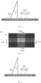
- the light shielding layer 612 located in the second optical filter part 614 is obliqued towards a side of the first optical filter part 613, and forms an angle ⁇ with the first direction.
- the light rays shielded by the light shielding layer 612 in the second optical filter part 614 are the light rays that form an included angle less than the angle ⁇ - ⁇ with the first direction, and the light rays that form an included angle greater than the angle ⁇ + ⁇ with the first direction.
- the included angle ⁇ ranges from 0 to ⁇ , and ⁇ is an included angle between an edge field of view main light rays emitted by the display assembly 10 and the first direction.
- FIG. 15 is a structural schematic view of another embodiment of an optical sub-filter of an embodiment illustrated in FIG. 14 of the present disclosure.
- the multiple light shielding layers 612 may include a first light shielding layer 6121 disposed parallel to the first direction, and multiple second light shielding layers 6122 disposed on two sides of the first light shielding layer 6121.
- Each of the second light shielding layers 6122 is obliqued towards one side of the first light shielding layer 6121.
- the second light shielding layer 6122 close to the first light shielding layer 6121 forms a first included angle with the first direction
- the second light shielding layer 6122 away from the first light shielding layer 6121 forms a second included angle with the first direction.
- the first included angle is less than or equal to the second included angle.
- first included angle can be mutually converted in some embodiments.
- first included angle in other embodiments is referred to as the "second included angle”
- second included angle the "second included angle” in other embodiments is referred to as the "third included angle”.
- each of the second light shielding layers 6122 forms an included angle ⁇ with the first direction.
- the second light shielding layer 6122 is used for shielding light rays having an included angle smaller than the angle ⁇ - ⁇ with the first direction, and is used for shielding light having an included angle greater than angle ⁇ + ⁇ with the first direction.
- the included angle ⁇ ranges from 0 to ⁇ , and ⁇ is an included angle between the edge field of view main light rays emitted by the display assembly 10 and the first direction.
- the first optical sub-filter 61 and the second optical sub-filter 62 are glued together.
- the optical filter 60 may be spaced apart from the lens assembly 20, and the optical filter 60 may also be bonded on the lens assembly 20.
- the first optical sub-filter 61 and the second optical sub-filter 62 are integrally formed.
- the light shielding layer 612 in the first optical sub-filter 61 extends into the second optical sub-filter 62, and is stacked with the light shielding layer 612 in the second optical sub-filter 62.
- the light shielding layer 612 in the second optical sub-filter 62 extends into the first optical sub-filter 61, and is stacked with the light shielding layer 612 in the first optical sub-filter 61, so as to reduce the thickness of the optical filter 60, thereby reducing the loss of effective light.
- FIG. 16 is a structural schematic view of another embodiment of the optical filter 60 of an embodiment illustrated in FIG. 8 of the present disclosure.
- FIG. 17 is a XVII-XVII cross-sectional schematic view of the optical filter 60 of an embodiment illustrated in FIG. 16 of the present disclosure.
- FIG. 18 is a XVIII-XVIII cross-sectional schematic view of the optical filter 60 of an embodiment illustrated in FIG. 16 of the present disclosure.
- the optical filter 60 may include multiple transparent parts 621, multiple first light shielding parts 622 disposed at intervals, and multiple second light shielding parts 632 disposed at intervals.
- the transparent parts 621 are disposed on a plane perpendicular to the first direction.
- the transparent part 621 is used for transmitting the light rays whose emergent angles meet the preset transmission condition.
- the first light shielding part 622 and the second light shielding part 632 are used for shielding the light rays whose emergent angles do not meet the preset transmission condition.
- the first light shielding part 622 and the second light shielding part 632 are disposed in a cross manner, and the transparent part 621 is located in the space formed by the intersection arrangement of the first light shielding part 622 and the second light shielding part 632.
- one first light shielding part 622 is disposed between two adjacent transparent parts 621, and one transparent part 621 is disposed between two adjacent first light shielding parts 622.
- One second light shielding part 632 is disposed between two adjacent transparent parts 621, and one transparent part 621 is disposed between two adjacent second light shielding parts 632.
- each of the second sub-light shielding parts 6222 forms an included angle ⁇ with the first direction.
- the second sub-light shielding part 6222 is used for shielding the light rays whose included angles with the first direction are smaller than an angle ⁇ - ⁇ , and is used for shielding the light whose included angles with first direction are greater than an angle ⁇ + ⁇ .
- multiple second light shielding parts 632 include a third sub-light shielding part 6321 parallel to the first direction, and multiple fourth sub-light shielding parts 6322 disposed on two sides of the third sub-light shielding part 6321.
- each of the fourth sub-light shielding parts 6322 is obliqued towards one side of the third sub-light shielding part 6321.
- an included angle between the fourth sub-light shielding part 6322 close to the third sub-light shielding part 6321 and the first direction is a fifth included angle
- an included angle between the fourth sub-light shielding part 6322 away from the third sub-light shielding part 6321 and the first direction is a sixth included angle
- the fifth included angle is less than or equal to the sixth included angle.
- each of the fourth sub-light shielding parts 6322 forms an included angle ⁇ with the first direction.
- the fourth sub-light shielding part 6322 is used for shielding the light rays whose included angles with the first direction are smaller than an angle ⁇ - ⁇ , and is used for shielding the light rays whose included angles with first direction are greater than an angle ⁇ + ⁇ .
- multiple first light shielding parts 622 can also be disposed according to the arrangement of the light shielding layer 612 illustrated in FIG. 14 .
- the multiple second light shielding parts 632 can also be disposed according to the arrangement of the light shielding layer 612 illustrated in Figure 14 .
- the angle ⁇ may be equal to the angle ⁇ .
- FIG. 19 is a structural schematic view of a near-to-eye display device 300 according to another embodiment of the present disclosure.
- the near-to-eye display device 300 may include a near-to-eye display optical system 200 and a housing 301 in which the near-to-eye display optical system 200 is mounted.
- the near-to-eye display optical system 200 may include the display assembly 10 (illustrated in FIG. 8 ) that emits the light rays having the virtual image information, the lens assembly 20 (illustrated in FIG. 8 ) that receives the light with the virtual image information and forms the virtual image on the focal plane, the first optical assembly 30 (illustrated in FIG.
- the near-to-eye display optical system 200 further includes the optical filter 60 (illustrated in FIG. 8 ) disposed between the display assembly 10 and the lens assembly 20.
- the optical filter 60 is used for receiving and transmitting the light rays having the virtual image information, so that the light rays having the virtual image information are transmitted through the lens assembly 20.
- the light rays reflected by the second optical assembly 40 pass through the first optical assembly 30 and enter the human eye 101.
- the display assembly 10, the lens assembly 20, the first optical assembly 30, the second optical assembly 40, and the optical filter 60 in the above-mentioned embodiments may be mounted on the housing 301.
- the disclosed method and devices may be accomplished in other ways.
- the device implementation described above is only schematic.
- the division of modules or units is only a logical function division, and there may be another division in actual implementation.
- multiple units or assemblies may be combined or integrated into another system, or some features may be ignored or not executed.
- the units described as separate parts may or may not be physically separated. Parts displayed as units may or may not be physical units, may be located in one place, or may be distributed on multiple network units. Some or all of the units may be selected according to actual needs to achieve the purpose of the schemes of the present embodiments.
- each functional unit can be integrated into one processing unit, each unit can physically exist separately, or two or more units can be integrated into one unit.
- the integrated units mentioned above can be realized in the form of hardware or software functional unit.
Landscapes
- Physics & Mathematics (AREA)
- General Physics & Mathematics (AREA)
- Optics & Photonics (AREA)
Claims (13)
- Augennahes optisches Anzeigesystem (100, 200), das Folgendes umfasst:eine Anzeigeeinheit (10), die so ausgebildet ist, dass sie Lichtstrahlen mit Bildinformationen emittiert;ein optisches Filter (60), das so ausgebildet ist, dass es die Lichtstrahlen durchlässt, deren Austrittswinkel eine vorgegebene Durchlassbedingung erfüllen, und die Lichtstrahlen abschirmt, deren Austrittswinkel die vorgegebene Durchlassbedingung nicht erfüllen;eine erste optische Baugruppe (30), die so ausgebildet ist, dass sie die durch das optische Filter (60) übertragenen Lichtstrahlen empfängt und reflektiert, wobei das optische Filter (60) zwischen der Anzeigeeinheit (10) und der ersten optischen Baugruppe (30) angeordnet ist; undeine zweite optische Baugruppe (40), die so ausgebildet ist, dass sie die von der ersten optischen Baugruppe (30) reflektierten Lichtstrahlen empfängt und die Lichtstrahlen an die erste optische Baugruppe (30) reflektiert, wobei die von der zweiten optischen Baugruppe (40) reflektierten Lichtstrahlen die erste optische Baugruppe (30) durchlaufen, um ein Bild auf einer Brennebene des augennahen optischen Anzeigesystems (100, 200) zu erzeugen;das optische Filter (60) ein optisches Unterfilter (61, 62) umfasst, das so ausgebildet ist, dass es die Lichtstrahlen durchlässt, deren Austrittswinkel die voreingestellte Durchlassbedingung erfüllen, und das optische Unterfilter (61, 62) mehrere transparente Schichten (611) und mehrere Lichtabschirmungsschichten (612) umfasst, die in einer ersten Richtung gestapelt sind; die mehreren transparenten Schichten (611) und die mehreren Lichtabschirmungsschichten (612) miteinander verbunden sind, eine Lichtabschirmungsschicht (612) zwischen zwei benachbarten der mehreren transparenten Schichten (611) angeordnet ist und eine transparente Schicht (611) zwischen zwei benachbarten der mehreren Lichtabschirmungsschichten (612) angeordnet ist; und die mehreren transparenten Schichten (611) so ausgebildet sind, dass sie die Lichtstrahlen durchlassen, deren Austrittswinkel die voreingestellte Durchlassbedingung erfüllen, die mehreren Lichtabschirmungsschichten (612) so ausgebildet sind, dass sie die Lichtstrahlen abschirmen, die erste Lichtstrahlen umfassen, und die ersten Lichtstrahlen die Lichtstrahlen sind, deren Austrittswinkel die voreingestellte Durchlassbedingung nicht erfüllen;dadurch gekennzeichnet, dass die mehreren transparenten Schichten (611) und die mehreren Lichtabschirmungsschichten (612) übereinander gestapelt sind und einen ersten optischen Filterteil (613) und zwei zweite optische Filterteile (614) bilden; der erste optische Filterteil (613) sich in der Mitte befindet und jede der beiden Seiten des ersten optischen Filterteils (613) mit einem zweiten optischen Filterteil (614) versehen ist; und der erste optische Filterteil (613) und der zweite optische Filterteil (614) miteinander verbunden sind, die mehreren Lichtabschirmungsschichten (612) in dem ersten optischen Filterteil (613) parallel zu einer zweiten Richtung sind und die erste Richtung senkrecht zu der zweiten Richtung ist.
- Augennahes optisches Anzeigesystem (100, 200) nach Anspruch 1, wobei die mehreren Lichtabschirmungsschichten (612) in dem ersten optischen Filterteil (613) ausgebildet sind, um die Lichtstrahlen abzuschirmen, deren eingeschlossene Winkel mit der zweiten Richtung größer als ein Winkel θ sind, und eine Beziehung zwischen dem Winkel θ und einer Bildquadrat-F-Zahl des augennahen optischen Anzeigesystems (100, 200) ist: 2tanθ = 1/F.
- Augennahes optisches Anzeigesystem (100, 200) nach Anspruch 2, wobei die Lichtabschirmungsschicht (612) in dem zweiten optischen Filterteil (614) schräg zu einer Seite des ersten optischen Filterteils (613) angeordnet ist und einen eingeschlossenen Winkel α mit der zweiten Richtung bildet; die mehreren Lichtabschirmungsschichten (612) in dem zweiten optischen Filterteil (614) ausgebildet sind, um die Lichtstrahlen abzuschirmen, deren eingeschlossene Winkel mit der zweiten Richtung kleiner als ein Winkel α - θ sind, und so ausgebildet sind, dass sie die Lichtstrahlen abschirmen, deren eingeschlossene Winkel mit der zweiten Richtung größer als ein Winkel α + θ sind; und der eingeschlossene Winkel α im Bereich von 0 bis β liegt und der eingeschlossene Winkel β ein eingeschlossener Winkel zwischen einem Randsichtfeld der Hauptlichtstrahlen, die von der Anzeigeeinheit (10) ausgesendet werden, und der zweiten Richtung ist.
- Augennahes optisches Anzeigesystem (100, 200) nach Anspruch 1, wobei die mehreren Lichtabschirmungsschichten (612) Folgendes umfassen:eine erste Lichtabschirmungsschicht (6121) parallel zu einer zweiten Richtung, wobei die erste Richtung senkrecht zur zweiten Richtung verläuft; undmehrere zweite Lichtabschirmungsschichten (6122), die auf zwei gegenüberliegenden Seiten der ersten Lichtabschirmungsschicht (6121) angeordnet sind, wobei jede der mehreren zweiten Lichtabschirmungsschichten (6122) schräg zu einer Seite der ersten Lichtabschirmungsschicht (6121) angeordnet ist;wobei in zwei benachbarten der mehreren zweiten Lichtabschirmungsschichten (6122) ein eingeschlossener Winkel zwischen der zweiten Lichtabschirmungsschicht (6122) nahe der ersten Lichtabschirmungsschicht (6121) und der zweiten Richtung ein erster eingeschlossener Winkel ist, ein eingeschlossener Winkel zwischen der zweiten Lichtabschirmungsschicht (6122) entfernt von der ersten Lichtabschirmungsschicht (6121) und der zweiten Richtung ein zweiter eingeschlossener Winkel ist und der erste eingeschlossene Winkel kleiner oder gleich dem zweiten eingeschlossenen Winkel ist.
- Augennahes optisches Anzeigesystem (100, 200) nach Anspruch 4, wobei jede der mehreren zweiten Lichtabschirmungsschichten (6122) einen eingeschlossenen Winkel α mit der zweiten Richtung bildet; die mehreren zweiten Lichtabschirmungsschichten (6122) so ausgebildet sind, dass sie die Lichtstrahlen abschirmen, deren eingeschlossene Winkel mit der zweiten Richtung kleiner als ein Winkel α - θ sind, und so ausgebildet sind, dass sie Lichtstrahlen abschirmen, deren eingeschlossene Winkel mit der zweiten Richtung größer als ein Winkel α + θ sind;
und der eingeschlossene Winkel α im Bereich von 0 bis β liegt, der eingeschlossene Winkel β ein eingeschlossener Winkel zwischen einem Randsichtfeld der Hauptlichtstrahlen der Anzeigeeinheit (10) und der zweiten Richtung ist, und eine Beziehung zwischen einem Winkel θ und einer Bildquadrat-F-Zahl des augennahen optischen Anzeigesystems (100, 200) ist: 2tanθ = 1/F. - Augennahes optisches Anzeigesystem (100, 200) nach einem der Ansprüche 1 bis 5, wobei die Anzahl der optischen Unterfilter (61, 62) zwei ist, die als ein erstes optisches Unterfilter (61) bzw. ein zweites optisches Unterfilter (62) bezeichnet werden; das erste optische Unterfilter (61) und das zweite optische Unterfilter (62) in der zweiten Richtung gestapelt sind; eine Richtung, in der die mehreren transparenten Schichten (611) und die mehreren Lichtabschirmungsschichten (612) des ersten optischen Unterfilters (61) gestapelt sind, eine erste Unterrichtung ist, eine Richtung, in der die mehreren transparenten Schichten (611) und die mehreren Lichtabschirmungsschichten (612) des zweiten optischen Unterfilters (62) gestapelt sind, eine zweite Unterrichtung ist, und die erste Unterrichtung senkrecht zu der zweiten Unterrichtung ist.
- Augennahes optisches Anzeigesystem (100, 200) nach Anspruch 1, wobei das optische Filter (60) Folgendes umfasst:mehrere transparente Teile (621), die in einer Ebene senkrecht zu einer zweiten Richtung angeordnet sind, wobei die mehreren transparenten Teile (621) so ausgebildet sind, dass sie die Lichtstrahlen durchlassen, deren Austrittswinkel eine vorgegebene Durchlassbedingung erfüllen;mehrere erste Lichtabschirmungsteile (622), die in Abständen angeordnet und so ausgebildet sind, dass sie Lichtstrahlen abschirmen, die erste Lichtstrahlen umfassen, wobei die ersten Lichtstrahlen die Lichtstrahlen sind, deren Austrittswinkel die voreingestellte Durchlassbedingung nicht erfüllen, einer der mehreren ersten Lichtabschirmungsteile (622) zwischen zwei benachbarten der mehreren transparenten Teile (621) angeordnet ist, und einer der mehreren transparenten Teile (621) zwischen zwei benachbarten der mehreren ersten Lichtabschirmungsteile (622) angeordnet ist; undmehrere zweite Lichtabschirmungsteile (632), die in Intervallen angeordnet sind und so ausgebildet sind, dass sie Lichtstrahlen abschirmen, deren Austrittswinkel die voreingestellte Durchlassbedingung nicht erfüllen, wobei einer der mehreren zweiten Lichtabschirmungsteile (632) zwischen zwei benachbarten der mehreren transparenten Teile (621) angeordnet ist, und einer der mehreren transparenten Teile (621) zwischen zwei benachbarten der mehreren zweiten Lichtabschirmungsteile (632) angeordnet ist.
- Augennahes optisches Anzeigesystem (100, 200) nach Anspruch 7, wobei jeder der mehreren ersten Lichtabschirmungsteile (622) Folgendes umfasst:einen ersten Unterlichtabschirmungsteil (6221) parallel zur zweiten Richtung; undmehrere zweite Unterlichtabschirmungsteile (6222), die auf zwei gegenüberliegenden Seiten des ersten Unterlichtabschirmungsteils (6221) angeordnet sind, wobei jeder der mehreren zweiten Unterlichtabschirmungsteile (6222) schräg zu einer Seite des ersten Unterlichtabschirmungsteils (6221) angeordnet ist;wobei in zwei benachbarten der mehreren zweiten Unterlichtabschirmungsteilen (6222) ein eingeschlossener Winkel zwischen dem zweiten Unterlichtabschirmungsteil (6222) nahe dem ersten Unterlichtabschirmungsteil (6221) und der zweiten Richtung ein dritter eingeschlossener Winkel ist, ein eingeschlossener Winkel zwischen dem zweiten Unterlichtabschirmungsteil (6222) entfernt von dem ersten Unterlichtabschirmungsteil (6221) und der zweiten Richtung ein vierter eingeschlossener Winkel ist, und der dritte eingeschlossene Winkel kleiner oder gleich dem vierten eingeschlossenen Winkel ist.
- Augennahes optisches Anzeigesystem (100, 200) nach Anspruch 8, wobei jeder der mehreren zweiten Unterlichtabschirmungsteile (6222) einen eingeschlossenen Winkel δ mit der zweiten Richtung bildet; mehrere zweite Unterlichtabschirmungsteile (6222) ausgebildet sind, um Lichtstrahlen abzuschirmen, deren eingeschlossene Winkel mit der zweiten Richtung kleiner sind als ein Winkel δ - θ, und so ausgebildet sind, dass sie Lichtstrahlen abschirmen, deren eingeschlossene Winkel mit der zweiten Richtung größer als ein Winkel δ + θ sind; und der eingeschlossene Winkel δ im Bereich von 0 bis β liegt, der eingeschlossene Winkel β ein eingeschlossener Winkel zwischen einem Randsichtfeld der Hauptlichtstrahlen der Anzeigeeinheit (10) und der zweiten Richtung ist, und eine Beziehung zwischen einem Winkel θ und einer Bildquadrat-F-Zahl des augennahen optischen Anzeigesystems (100, 200) ist: 2tanθ = 1/F.
- Augennahes optisches Anzeigesystem (100, 200) nach Anspruch 7, wobei jeder der mehreren zweiten Lichtabschirmteile (632) Folgendes umfasst:einen dritten Unterlichtabschirmungsteil (6321) parallel zur zweiten Richtung; undmehrere vierte Unterlichtabschirmungsteile (6322), die auf zwei gegenüberliegenden Seiten des dritten Unterlichtabschirmungsteils (6321) angeordnet sind, wobei jeder der mehreren vierten Unterlichtabschirmungsteile (6322) schräg zu einer Seite des dritten Unterlichtabschirmungsteils (6321) angeordnet ist;wobei in zwei benachbarten der mehreren vierten Unterlichtabschirmungsteile (6322) ein eingeschlossener Winkel zwischen dem vierten Unterlichtabschirmungsteil (6322) nahe dem dritten Unterlichtabschirmungsteil (6321) und der zweiten Richtung ein fünfter eingeschlossener Winkel ist, ein eingeschlossener Winkel zwischen dem vierten Unterlichtabschirmungsteil (6322) entfernt von dem dritten Unterlichtabschirmungsteil (6321) und der zweiten Richtung ein sechster eingeschlossener Winkel ist, und der fünfte eingeschlossene Winkel kleiner oder gleich dem sechsten eingeschlossenen Winkel ist.
- Augennahes optisches Anzeigesystem (100, 200) nach Anspruch 10, wobei jeder der mehreren vierten Unterlichtabschirmungsteile (6322) einen eingeschlossenen Winkel λ mit der zweiten Richtung bildet, die mehreren vierten Unterlichtabschirmungsteile (6322) ausgebildet sind, um Lichtstrahlen abzuschirmen, deren eingeschlossene Winkel mit der zweiten Richtung kleiner sind als ein Winkel λ - θ, und ausgebildet sind, um Lichtstrahlen abzuschirmen, deren eingeschlossene Winkel mit der zweiten Richtung größer als ein Winkel λ + θ sind; und der eingeschlossene Winkel λ im Bereich von 0 bis β liegt, der eingeschlossene Winkel β ein eingeschlossener Winkel zwischen einem Randsichtfeld der Hauptlichtstrahlen der Anzeigeeinheit (10) und der zweiten Richtung ist, und eine Beziehung zwischen einem Winkel θ und einer Bildquadrat-F-Zahl des augennahen optischen Anzeigesystems (100, 200) ist: 2tanθ = 1/F.
- Augennahes optisches Anzeigesystem (100, 200) nach einem der Ansprüche 1 bis 5 und 7 bis 11, das ferner Folgendes umfasst:
eine Linsenbaugruppe (20), die zwischen dem optischen Filter (60) und der ersten optischen Baugruppe (30) angeordnet und so ausgebildet ist, dass sie die durch das optische Filter (60) hindurchtretenden Lichtstrahlen empfängt und durchlässt, und so ausgebildet ist, dass sie die Lichtstrahlen fokussiert, wobei die erste optische Baugruppe (30) so ausgebildet ist, dass sie von der Linsenbaugruppe (20) fokussierte Lichtstrahlen empfängt und reflektiert. - Augennahe Anzeigevorrichtung, dadurch gekennzeichnet, dass sie Folgendes umfasst:ein Gehäuse (301); undein augennahes optisches Anzeigesystem (100, 200) nach einem der Ansprüche 1 bis 12, wobei das augennahe optische Anzeigesystem (100, 200) an dem Gehäuse befestigt ist.
Applications Claiming Priority (2)
| Application Number | Priority Date | Filing Date | Title |
|---|---|---|---|
| CN202110285802.1A CN113009697A (zh) | 2021-03-17 | 2021-03-17 | 近眼显示光学系统及近眼显示设备 |
| PCT/CN2022/075908 WO2022193880A1 (zh) | 2021-03-17 | 2022-02-10 | 近眼显示光学系统、滤光件及近眼显示设备 |
Publications (3)
| Publication Number | Publication Date |
|---|---|
| EP4303641A1 EP4303641A1 (de) | 2024-01-10 |
| EP4303641A4 EP4303641A4 (de) | 2024-07-24 |
| EP4303641B1 true EP4303641B1 (de) | 2025-06-25 |
Family
ID=76409224
Family Applications (1)
| Application Number | Title | Priority Date | Filing Date |
|---|---|---|---|
| EP22770235.4A Active EP4303641B1 (de) | 2021-03-17 | 2022-02-10 | Augennahes optisches anzeigesystem, optischer filter und augennahe anzeigevorrichtung |
Country Status (4)
| Country | Link |
|---|---|
| US (1) | US20230393404A1 (de) |
| EP (1) | EP4303641B1 (de) |
| CN (1) | CN113009697A (de) |
| WO (1) | WO2022193880A1 (de) |
Families Citing this family (6)
| Publication number | Priority date | Publication date | Assignee | Title |
|---|---|---|---|---|
| CN113009697A (zh) * | 2021-03-17 | 2021-06-22 | Oppo广东移动通信有限公司 | 近眼显示光学系统及近眼显示设备 |
| CN113759553B (zh) * | 2021-09-03 | 2024-04-09 | 融信信息科技有限公司 | 一种全息波导显示装置 |
| CN114740628A (zh) * | 2022-06-14 | 2022-07-12 | 龙旗电子(惠州)有限公司 | 增强现实光学装置 |
| WO2025079280A1 (ja) * | 2023-10-11 | 2025-04-17 | アルディーテック株式会社 | パンフォーカス眼鏡、xrグラスおよびコリメート機能付きコンタクトレンズ |
| JP7549932B1 (ja) | 2024-01-11 | 2024-09-12 | アルディーテック株式会社 | パンフォーカス眼鏡およびxrグラス |
| EP4564080A1 (de) * | 2023-11-28 | 2025-06-04 | Snap Inc. | Lichtprojektor |
Family Cites Families (16)
| Publication number | Priority date | Publication date | Assignee | Title |
|---|---|---|---|---|
| US7042610B1 (en) * | 2003-02-20 | 2006-05-09 | Lightmaster Systems, Inc. | Method and apparatus for improved waveplates and suppression of stray light in LCoS kernel applications |
| JP2012020549A (ja) * | 2010-07-16 | 2012-02-02 | Fuji Xerox Co Ltd | 露光装置及び画像形成装置 |
| JP2013257529A (ja) * | 2012-05-18 | 2013-12-26 | Sharp Corp | 光学システム |
| JP6405627B2 (ja) * | 2013-12-25 | 2018-10-17 | 日本精機株式会社 | 死角補助装置 |
| US9594246B2 (en) * | 2014-01-21 | 2017-03-14 | Osterhout Group, Inc. | See-through computer display systems |
| US20170115486A1 (en) * | 2015-10-22 | 2017-04-27 | Osterhout Group, Inc. | Control of grazing angle stray light |
| TWI782990B (zh) * | 2017-06-05 | 2022-11-11 | 日商信越聚合物股份有限公司 | 視角控制體及其製造方法,以及視角控制圖像顯示體 |
| GB201708963D0 (en) * | 2017-06-06 | 2017-07-19 | Wave Optics Ltd | Head-mounted augmented reality system |
| US20190212482A1 (en) * | 2018-01-10 | 2019-07-11 | Oculus Vr, Llc | Angle selective filter for near eye displays |
| EP3752869A4 (de) * | 2018-02-15 | 2021-11-17 | TDG Acquisition Company LLC d/b/a Six 15 Technologies | Optik und anordnung für reduzierte reflexionen |
| CN109521508B (zh) * | 2018-12-11 | 2024-01-23 | 杭州炽云科技有限公司 | 一种带有防窥膜材的虚像成像系统 |
| CN110873967A (zh) * | 2019-11-28 | 2020-03-10 | Oppo广东移动通信有限公司 | 一种近眼显示光学系统及头戴式显示器 |
| CN111308715B (zh) * | 2020-03-31 | 2022-05-10 | 优奈柯恩(北京)科技有限公司 | 显示设备 |
| CN111638602B (zh) * | 2020-07-03 | 2022-05-24 | 维沃移动通信有限公司 | 光学装置及近眼显示设备 |
| CN112163482A (zh) * | 2020-09-16 | 2021-01-01 | 瑞芯微电子股份有限公司 | 一种光学准直器、指纹识别模组及电子设备 |
| CN113009697A (zh) * | 2021-03-17 | 2021-06-22 | Oppo广东移动通信有限公司 | 近眼显示光学系统及近眼显示设备 |
-
2021
- 2021-03-17 CN CN202110285802.1A patent/CN113009697A/zh active Pending
-
2022
- 2022-02-10 WO PCT/CN2022/075908 patent/WO2022193880A1/zh not_active Ceased
- 2022-02-10 EP EP22770235.4A patent/EP4303641B1/de active Active
-
2023
- 2023-08-21 US US18/452,655 patent/US20230393404A1/en active Pending
Also Published As
| Publication number | Publication date |
|---|---|
| EP4303641A1 (de) | 2024-01-10 |
| WO2022193880A1 (zh) | 2022-09-22 |
| EP4303641A4 (de) | 2024-07-24 |
| CN113009697A (zh) | 2021-06-22 |
| US20230393404A1 (en) | 2023-12-07 |
Similar Documents
| Publication | Publication Date | Title |
|---|---|---|
| EP4303641B1 (de) | Augennahes optisches anzeigesystem, optischer filter und augennahe anzeigevorrichtung | |
| US11500205B2 (en) | Wearable AR system, AR display device and its projection source module | |
| US10386563B2 (en) | Illuminator for a wearable display | |
| US9013793B2 (en) | Lightweight eyepiece for head mounted display | |
| KR102578625B1 (ko) | 기판 유도식 광학 장치 | |
| AU2004271392B2 (en) | Substrate-guided optical devices | |
| US8000020B2 (en) | Substrate-guided imaging lens | |
| KR20210119996A (ko) | 작은 입력 개구를 갖는 고효율 콤팩트 헤드 마운트 디스플레이 시스템 | |
| US20190369399A1 (en) | Head-mounted display device | |
| KR20190000456U (ko) | 소형 시준 이미지 프로젝터를 구비한 광학 시스템 | |
| CN114859560B (zh) | 光学模组以及头戴显示设备 | |
| WO2021119021A2 (en) | Near-eye optical system implementing a waveguide with an output viewer element having a refractive beam-splitting convex lens | |
| CN117075337A (zh) | 光学模组以及头戴显示设备 | |
| JP2022063534A (ja) | 表示装置 | |
| CN114488538B (zh) | Ar光机和头戴显示设备 | |
| CN113376841A (zh) | 显示系统 | |
| US20220113595A1 (en) | Display device | |
| CN221125002U (zh) | 一种光机模组 | |
| EP3761103B1 (de) | Kopfmontierte anzeigevorrichtung | |
| US20250004276A1 (en) | Virtual image display device and optical unit | |
| US20240418996A1 (en) | Display device | |
| JP2025073225A (ja) | 虚像表示装置及び光学ユニット | |
| JP2026004785A (ja) | 虚像表示装置及び光学ユニット | |
| WO2023168861A1 (zh) | 一种光学投影系统以及电子设备 | |
| JP2025006920A (ja) | 虚像表示装置及び光学ユニット |
Legal Events
| Date | Code | Title | Description |
|---|---|---|---|
| STAA | Information on the status of an ep patent application or granted ep patent |
Free format text: STATUS: THE INTERNATIONAL PUBLICATION HAS BEEN MADE |
|
| PUAI | Public reference made under article 153(3) epc to a published international application that has entered the european phase |
Free format text: ORIGINAL CODE: 0009012 |
|
| STAA | Information on the status of an ep patent application or granted ep patent |
Free format text: STATUS: REQUEST FOR EXAMINATION WAS MADE |
|
| 17P | Request for examination filed |
Effective date: 20231003 |
|
| AK | Designated contracting states |
Kind code of ref document: A1 Designated state(s): AL AT BE BG CH CY CZ DE DK EE ES FI FR GB GR HR HU IE IS IT LI LT LU LV MC MK MT NL NO PL PT RO RS SE SI SK SM TR |
|
| DAV | Request for validation of the european patent (deleted) | ||
| DAX | Request for extension of the european patent (deleted) | ||
| A4 | Supplementary search report drawn up and despatched |
Effective date: 20240626 |
|
| RIC1 | Information provided on ipc code assigned before grant |
Ipc: G02B 27/01 20060101AFI20240620BHEP |
|
| GRAP | Despatch of communication of intention to grant a patent |
Free format text: ORIGINAL CODE: EPIDOSNIGR1 |
|
| STAA | Information on the status of an ep patent application or granted ep patent |
Free format text: STATUS: GRANT OF PATENT IS INTENDED |
|
| INTG | Intention to grant announced |
Effective date: 20250324 |
|
| GRAS | Grant fee paid |
Free format text: ORIGINAL CODE: EPIDOSNIGR3 |
|
| GRAA | (expected) grant |
Free format text: ORIGINAL CODE: 0009210 |
|
| STAA | Information on the status of an ep patent application or granted ep patent |
Free format text: STATUS: THE PATENT HAS BEEN GRANTED |
|
| AK | Designated contracting states |
Kind code of ref document: B1 Designated state(s): AL AT BE BG CH CY CZ DE DK EE ES FI FR GB GR HR HU IE IS IT LI LT LU LV MC MK MT NL NO PL PT RO RS SE SI SK SM TR |
|
| REG | Reference to a national code |
Ref country code: GB Ref legal event code: FG4D |
|
| REG | Reference to a national code |
Ref country code: CH Ref legal event code: EP |
|
| REG | Reference to a national code |
Ref country code: DE Ref legal event code: R096 Ref document number: 602022016554 Country of ref document: DE |
|
| REG | Reference to a national code |
Ref country code: CH Ref legal event code: EP |
|
| REG | Reference to a national code |
Ref country code: IE Ref legal event code: FG4D |
|
| P01 | Opt-out of the competence of the unified patent court (upc) registered |
Free format text: CASE NUMBER: UPC_APP_5177_4303641/2025 Effective date: 20250829 |
|
| PG25 | Lapsed in a contracting state [announced via postgrant information from national office to epo] |
Ref country code: FI Free format text: LAPSE BECAUSE OF FAILURE TO SUBMIT A TRANSLATION OF THE DESCRIPTION OR TO PAY THE FEE WITHIN THE PRESCRIBED TIME-LIMIT Effective date: 20250625 |
|
| REG | Reference to a national code |
Ref country code: LT Ref legal event code: MG9D |
|
| PG25 | Lapsed in a contracting state [announced via postgrant information from national office to epo] |
Ref country code: NO Free format text: LAPSE BECAUSE OF FAILURE TO SUBMIT A TRANSLATION OF THE DESCRIPTION OR TO PAY THE FEE WITHIN THE PRESCRIBED TIME-LIMIT Effective date: 20250925 Ref country code: GR Free format text: LAPSE BECAUSE OF FAILURE TO SUBMIT A TRANSLATION OF THE DESCRIPTION OR TO PAY THE FEE WITHIN THE PRESCRIBED TIME-LIMIT Effective date: 20250926 |
|
| PG25 | Lapsed in a contracting state [announced via postgrant information from national office to epo] |
Ref country code: BG Free format text: LAPSE BECAUSE OF FAILURE TO SUBMIT A TRANSLATION OF THE DESCRIPTION OR TO PAY THE FEE WITHIN THE PRESCRIBED TIME-LIMIT Effective date: 20250625 |
|
| PG25 | Lapsed in a contracting state [announced via postgrant information from national office to epo] |
Ref country code: HR Free format text: LAPSE BECAUSE OF FAILURE TO SUBMIT A TRANSLATION OF THE DESCRIPTION OR TO PAY THE FEE WITHIN THE PRESCRIBED TIME-LIMIT Effective date: 20250625 |
|
| PG25 | Lapsed in a contracting state [announced via postgrant information from national office to epo] |
Ref country code: RS Free format text: LAPSE BECAUSE OF FAILURE TO SUBMIT A TRANSLATION OF THE DESCRIPTION OR TO PAY THE FEE WITHIN THE PRESCRIBED TIME-LIMIT Effective date: 20250925 |
|
| PG25 | Lapsed in a contracting state [announced via postgrant information from national office to epo] |
Ref country code: LV Free format text: LAPSE BECAUSE OF FAILURE TO SUBMIT A TRANSLATION OF THE DESCRIPTION OR TO PAY THE FEE WITHIN THE PRESCRIBED TIME-LIMIT Effective date: 20250625 |
|
| REG | Reference to a national code |
Ref country code: NL Ref legal event code: MP Effective date: 20250625 |
|
| PG25 | Lapsed in a contracting state [announced via postgrant information from national office to epo] |
Ref country code: NL Free format text: LAPSE BECAUSE OF FAILURE TO SUBMIT A TRANSLATION OF THE DESCRIPTION OR TO PAY THE FEE WITHIN THE PRESCRIBED TIME-LIMIT Effective date: 20250625 |
|
| PG25 | Lapsed in a contracting state [announced via postgrant information from national office to epo] |
Ref country code: PT Free format text: LAPSE BECAUSE OF FAILURE TO SUBMIT A TRANSLATION OF THE DESCRIPTION OR TO PAY THE FEE WITHIN THE PRESCRIBED TIME-LIMIT Effective date: 20251027 |
|
| REG | Reference to a national code |
Ref country code: AT Ref legal event code: MK05 Ref document number: 1807061 Country of ref document: AT Kind code of ref document: T Effective date: 20250625 |
|
| PG25 | Lapsed in a contracting state [announced via postgrant information from national office to epo] |
Ref country code: IS Free format text: LAPSE BECAUSE OF FAILURE TO SUBMIT A TRANSLATION OF THE DESCRIPTION OR TO PAY THE FEE WITHIN THE PRESCRIBED TIME-LIMIT Effective date: 20251025 |
|
| PG25 | Lapsed in a contracting state [announced via postgrant information from national office to epo] |
Ref country code: AT Free format text: LAPSE BECAUSE OF FAILURE TO SUBMIT A TRANSLATION OF THE DESCRIPTION OR TO PAY THE FEE WITHIN THE PRESCRIBED TIME-LIMIT Effective date: 20250625 Ref country code: SM Free format text: LAPSE BECAUSE OF FAILURE TO SUBMIT A TRANSLATION OF THE DESCRIPTION OR TO PAY THE FEE WITHIN THE PRESCRIBED TIME-LIMIT Effective date: 20250625 |
|
| PG25 | Lapsed in a contracting state [announced via postgrant information from national office to epo] |
Ref country code: CZ Free format text: LAPSE BECAUSE OF FAILURE TO SUBMIT A TRANSLATION OF THE DESCRIPTION OR TO PAY THE FEE WITHIN THE PRESCRIBED TIME-LIMIT Effective date: 20250625 |
|
| PG25 | Lapsed in a contracting state [announced via postgrant information from national office to epo] |
Ref country code: PL Free format text: LAPSE BECAUSE OF FAILURE TO SUBMIT A TRANSLATION OF THE DESCRIPTION OR TO PAY THE FEE WITHIN THE PRESCRIBED TIME-LIMIT Effective date: 20250625 |
|
| PG25 | Lapsed in a contracting state [announced via postgrant information from national office to epo] |
Ref country code: EE Free format text: LAPSE BECAUSE OF FAILURE TO SUBMIT A TRANSLATION OF THE DESCRIPTION OR TO PAY THE FEE WITHIN THE PRESCRIBED TIME-LIMIT Effective date: 20250625 |
|
| PG25 | Lapsed in a contracting state [announced via postgrant information from national office to epo] |
Ref country code: SK Free format text: LAPSE BECAUSE OF FAILURE TO SUBMIT A TRANSLATION OF THE DESCRIPTION OR TO PAY THE FEE WITHIN THE PRESCRIBED TIME-LIMIT Effective date: 20250625 |
|
| PG25 | Lapsed in a contracting state [announced via postgrant information from national office to epo] |
Ref country code: ES Free format text: LAPSE BECAUSE OF FAILURE TO SUBMIT A TRANSLATION OF THE DESCRIPTION OR TO PAY THE FEE WITHIN THE PRESCRIBED TIME-LIMIT Effective date: 20250625 |