EP4303476A1 - Flow rate control valve - Google Patents
Flow rate control valve Download PDFInfo
- Publication number
- EP4303476A1 EP4303476A1 EP22762882.3A EP22762882A EP4303476A1 EP 4303476 A1 EP4303476 A1 EP 4303476A1 EP 22762882 A EP22762882 A EP 22762882A EP 4303476 A1 EP4303476 A1 EP 4303476A1
- Authority
- EP
- European Patent Office
- Prior art keywords
- valve
- gear
- flow rate
- engagement portion
- rate control
- Prior art date
- Legal status (The legal status is an assumption and is not a legal conclusion. Google has not performed a legal analysis and makes no representation as to the accuracy of the status listed.)
- Pending
Links
- 230000033001 locomotion Effects 0.000 claims abstract description 24
- 238000006243 chemical reaction Methods 0.000 claims abstract description 10
- 239000003507 refrigerant Substances 0.000 description 12
- 230000005540 biological transmission Effects 0.000 description 11
- 239000002184 metal Substances 0.000 description 7
- 229910052751 metal Inorganic materials 0.000 description 7
- 230000000717 retained effect Effects 0.000 description 7
- 230000008878 coupling Effects 0.000 description 5
- 238000010168 coupling process Methods 0.000 description 5
- 238000005859 coupling reaction Methods 0.000 description 5
- 238000005057 refrigeration Methods 0.000 description 5
- 230000002093 peripheral effect Effects 0.000 description 4
- 238000007789 sealing Methods 0.000 description 4
- 230000035939 shock Effects 0.000 description 4
- 239000004734 Polyphenylene sulfide Substances 0.000 description 3
- 230000000694 effects Effects 0.000 description 3
- 238000000465 moulding Methods 0.000 description 3
- 239000004033 plastic Substances 0.000 description 3
- 229920000069 polyphenylene sulfide Polymers 0.000 description 3
- 229920001343 polytetrafluoroethylene Polymers 0.000 description 3
- 239000004810 polytetrafluoroethylene Substances 0.000 description 3
- 239000011347 resin Substances 0.000 description 3
- 229920005989 resin Polymers 0.000 description 3
- 125000006850 spacer group Chemical group 0.000 description 3
- 239000012530 fluid Substances 0.000 description 2
- 238000007373 indentation Methods 0.000 description 2
- 230000003313 weakening effect Effects 0.000 description 2
- 229910001297 Zn alloy Inorganic materials 0.000 description 1
- 239000004519 grease Substances 0.000 description 1
- 239000000314 lubricant Substances 0.000 description 1
- 239000000696 magnetic material Substances 0.000 description 1
- 239000000463 material Substances 0.000 description 1
- -1 polytetrafluoroethylene Polymers 0.000 description 1
- 230000036316 preload Effects 0.000 description 1
- 238000003466 welding Methods 0.000 description 1
Images





Classifications
-
- F—MECHANICAL ENGINEERING; LIGHTING; HEATING; WEAPONS; BLASTING
- F16—ENGINEERING ELEMENTS AND UNITS; GENERAL MEASURES FOR PRODUCING AND MAINTAINING EFFECTIVE FUNCTIONING OF MACHINES OR INSTALLATIONS; THERMAL INSULATION IN GENERAL
- F16K—VALVES; TAPS; COCKS; ACTUATING-FLOATS; DEVICES FOR VENTING OR AERATING
- F16K31/00—Actuating devices; Operating means; Releasing devices
- F16K31/44—Mechanical actuating means
- F16K31/50—Mechanical actuating means with screw-spindle or internally threaded actuating means
-
- F—MECHANICAL ENGINEERING; LIGHTING; HEATING; WEAPONS; BLASTING
- F16—ENGINEERING ELEMENTS AND UNITS; GENERAL MEASURES FOR PRODUCING AND MAINTAINING EFFECTIVE FUNCTIONING OF MACHINES OR INSTALLATIONS; THERMAL INSULATION IN GENERAL
- F16K—VALVES; TAPS; COCKS; ACTUATING-FLOATS; DEVICES FOR VENTING OR AERATING
- F16K1/00—Lift valves or globe valves, i.e. cut-off apparatus with closure members having at least a component of their opening and closing motion perpendicular to the closing faces
- F16K1/32—Details
- F16K1/52—Means for additional adjustment of the rate of flow
- F16K1/523—Means for additional adjustment of the rate of flow for limiting the maximum flow rate, using a stop
-
- F—MECHANICAL ENGINEERING; LIGHTING; HEATING; WEAPONS; BLASTING
- F16—ENGINEERING ELEMENTS AND UNITS; GENERAL MEASURES FOR PRODUCING AND MAINTAINING EFFECTIVE FUNCTIONING OF MACHINES OR INSTALLATIONS; THERMAL INSULATION IN GENERAL
- F16K—VALVES; TAPS; COCKS; ACTUATING-FLOATS; DEVICES FOR VENTING OR AERATING
- F16K31/00—Actuating devices; Operating means; Releasing devices
- F16K31/02—Actuating devices; Operating means; Releasing devices electric; magnetic
- F16K31/04—Actuating devices; Operating means; Releasing devices electric; magnetic using a motor
- F16K31/047—Actuating devices; Operating means; Releasing devices electric; magnetic using a motor characterised by mechanical means between the motor and the valve, e.g. lost motion means reducing backlash, clutches, brakes or return means
-
- F—MECHANICAL ENGINEERING; LIGHTING; HEATING; WEAPONS; BLASTING
- F16—ENGINEERING ELEMENTS AND UNITS; GENERAL MEASURES FOR PRODUCING AND MAINTAINING EFFECTIVE FUNCTIONING OF MACHINES OR INSTALLATIONS; THERMAL INSULATION IN GENERAL
- F16K—VALVES; TAPS; COCKS; ACTUATING-FLOATS; DEVICES FOR VENTING OR AERATING
- F16K31/00—Actuating devices; Operating means; Releasing devices
- F16K31/44—Mechanical actuating means
- F16K31/53—Mechanical actuating means with toothed gearing
-
- F—MECHANICAL ENGINEERING; LIGHTING; HEATING; WEAPONS; BLASTING
- F16—ENGINEERING ELEMENTS AND UNITS; GENERAL MEASURES FOR PRODUCING AND MAINTAINING EFFECTIVE FUNCTIONING OF MACHINES OR INSTALLATIONS; THERMAL INSULATION IN GENERAL
- F16K—VALVES; TAPS; COCKS; ACTUATING-FLOATS; DEVICES FOR VENTING OR AERATING
- F16K41/00—Spindle sealings
- F16K41/10—Spindle sealings with diaphragm, e.g. shaped as bellows or tube
-
- Y—GENERAL TAGGING OF NEW TECHNOLOGICAL DEVELOPMENTS; GENERAL TAGGING OF CROSS-SECTIONAL TECHNOLOGIES SPANNING OVER SEVERAL SECTIONS OF THE IPC; TECHNICAL SUBJECTS COVERED BY FORMER USPC CROSS-REFERENCE ART COLLECTIONS [XRACs] AND DIGESTS
- Y02—TECHNOLOGIES OR APPLICATIONS FOR MITIGATION OR ADAPTATION AGAINST CLIMATE CHANGE
- Y02B—CLIMATE CHANGE MITIGATION TECHNOLOGIES RELATED TO BUILDINGS, e.g. HOUSING, HOUSE APPLIANCES OR RELATED END-USER APPLICATIONS
- Y02B30/00—Energy efficient heating, ventilation or air conditioning [HVAC]
- Y02B30/70—Efficient control or regulation technologies, e.g. for control of refrigerant flow, motor or heating
Definitions
- the present invention relates to a flow rate control valve.
- refrigeration cycles adopted in room air conditioners and car air conditioners are equipped with a flow rate control valve for controlling the flow rate of a refrigerant, in addition to a compressor, an outdoor heat exchanger, an indoor heat exchanger, an expansion valve, etc.
- a gear type motor-operated valve disclosed in Patent Literature 1 is known as one example of such a flow rate control valve.
- This gear type motor-operated valve reduces a rotational force output from a stepping motor via a reduction mechanism, and further converts the reduced rotational force into an axial direction force using a screw mechanism and transmits the same to a valve element. Thereby, the valve element is separated from or seated on a valve seat, by which valve opening and closing operations are executed.
- the rotational force of the stepping motor is reduced by a reduction device, such that a pressing force applied to the valve seat from the valve element when closing the valve is relatively high, and there is an advantage in that a sealing capability when closing the valve can be maintained to a high level.
- An object of the present invention is to provide a flow rate control valve capable of suppressing foreign matter from being bitten therein and capable of performing appropriate flow rate control.
- the present invention enables to provide a flow rate control valve capable of suppressing foreign matter from being bitten therein and capable of performing appropriate flow rate control.
- a flow rate control valve according to an embodiment of the present invention is disposed within a circulation circuit of a refrigeration cycle apparatus, and it controls a flow rate of refrigerant flowing within the circulation circuit.
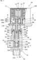
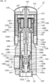
- FIG. 1 is a longitudinal cross-sectional view illustrating a valve closed state of a flow rate control valve 1 according to a first embodiment
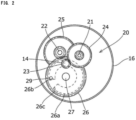
- FIG. 2 is a planar view of a cross-section taken at line A-A of the flow rate control valve 1 illustrated in FIG. 1
- FIG. 3 is a longitudinal cross-sectional view illustrating a valve opened state of the flow rate control valve 1 according to the first embodiment
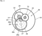
- FIG. 4 is a planar view of a cross-section similar to FIG. 2 of the flow rate control valve illustrated in FIG. 3
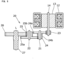
- FIG. 5 is a view in which a gear train adopted in the flow rate control valve 1 is illustrated in expansion such that the axis lines of the respective gears are positioned within the same plane, but with a portion thereof simplified.
- the flow rate control valve 1 includes a driving unit 10, a reduction unit 20, and a valve mechanism unit 30.
- An axis line of the valve mechanism unit 30 is denoted as L.
- a side on which a motor is arranged is referred to as an upper side
- a side on which a valve element is arranged is referred to as a lower side.
- the driving unit 10 includes a driving unit case 11, a stator 12 attached to an inner side of the driving unit case 11, a rotor 13 arranged on an inner side in a radial direction of the stator 12, and a drive shaft 14 fixed to the rotor 13.
- the stator 12 and the rotor 13 constitute a stepping motor.
- the driving source is not limited to the stepping motor, and it can be a brushless motor or a motor with a brush.
- the driving unit case 11 is formed in the shape of a cylinder with a top part, and a bearing 15 is fixed to a lower surface at a center of the top part.
- the bearing 15 retains the drive shaft 14 rotatably.
- a support cylinder 16 formed in the shape of a cylinder with a top part is disposed so as to fit to an inner circumference of the driving unit case 11 at a lower side of the stator 12 and the rotor 13.
- a lower end of the support cylinder 16 is in contact with an upper surface of an annular member 17 sealing the driving unit case 11, and the lower end of the driving unit case 11 and an outer circumference of the annular member 17 are fixed by caulking.
- the support cylinder 16 includes a hollow cylinder portion 16a formed on a lower surface at a center of the top part, and a through hole (not shown). A lower end of the drive shaft 14 passes through the through hole of the support cylinder 16 and is rotatably supported in the through hole.
- the reduction unit 20 includes a first shaft 21 and a second shaft 22 each having both ends thereof retained by a lower surface of the top part of the support cylinder 16 and an upper surface of the annular member 17, a drive gear 23 fixed to a lower end of the drive shaft 14 passing through the through hole of the support cylinder 16, a first transmission gear 24 retained rotatably with respect to the first shaft 21, a second transmission gear 25 retained rotatably with respect to the second shaft 22, a final gear 26, a male screw shaft 27, and a female screw cylinder 28.
- the final gear 26 constitutes a rotating body
- the male screw shaft 27 constitutes a moving body.
- the male screw shaft 27 is press-fit to and integrated with the final gear 26.
- the first shaft 21 and the second shaft 22 are arranged in parallel with the drive shaft 14.
- the first transmission gear 24 is formed by connecting a first input gear portion 24a meshing with the drive gear 23 and a first output gear portion 24b coaxially.
- the second transmission gear 25 is formed by connecting a second input gear portion 25a meshing with the first output gear portion 24b and a second output gear portion 25b meshing with the final gear 26 coaxially.
- the respective shafts can be formed of metal and the respective gears can be formed of resin.
- the drive gear 23, the first transmission gear 24, the second transmission gear 25, and the final gear 26 constitute a gear train.
- a number of teeth ZA of the drive gear 23 is smaller than a number of teeth ZB of the first input gear portion 24a.
- a number of teeth ZC of the first output gear portion 24b is smaller than a number of teeth ZD of the second input gear portion 25a.
- a number of teeth ZE of the second output gear portion 25b is smaller than a number of teeth ZF of the final gear 26. Therefore, while the rotational force is transmitted from the drive gear 23 to the final gear 26, reduction at a reduction ratio of (ZB/ZA) ⁇ (ZD/ZC) ⁇ (ZF/ZE) is realized.
- the final gear 26 includes an arc-shaped groove 26a formed on a lower surface thereof so as to surround the male screw shaft 27.
- One end in a circumferential direction of the arc-shaped groove 26a is referred to as an end portion 26b, and the other end thereof is referred to as an end portion 26c.
- An angle from the end portion 26b to the end portion 26c is set to a predetermined value.
- the end portion 26b constitutes a first engagement portion
- the end portion 26c constitutes a third engagement portion.
- the first engagement portion and the third engagement portion will be described later.
- the final gear 26 constitutes a rotating body, but the rotating body is not limited to the final gear 26.
- any member that rotates by receiving rotational force from the rotor 13 and that includes at least a first engagement portion that moves toward or away from a second engagement portion of a valve body 31 according to rotation can be adopted as the rotating body.
- a hole 17a is formed on an upper surface of the annular member 17, and a lower end of a pin 29 is fit and fixed to the hole 17a. Further, an upper end of the pin 29 is arranged to be positioned within the arc-shaped groove 26a.
- the pin 29 constitutes a second engagement portion and a fourth engagement portion arranged on the valve body 31. "Arranged on the valve body 31" refers not only to a state being directly arranged on the valve body 31 but also to a state indirectly arranged on another member fixed to the valve body 31. The second engagement portion and the fourth engagement portion will be described later.
- the male screw shaft 27 is arranged such that the upper end thereof is fit to an inner circumference 16b of the hollow cylinder portion 16a of the support cylinder 16, and it is arranged in a manner capable of being relatively rotated and displaced in an axial direction within the hollow cylinder portion 16a. Further, the final gear 26 is fit and fixed at an intermediate position of the male screw shaft 27, and a male screw 27a is formed on an outer circumference of a lower end side of the male screw shaft 27.
- the female screw cylinder 28 having a hollow cylindrical shape is fit and fixed to an inner circumference to the annular member 17 at an upper end side that is reduced in diameter, and includes a through hole 28a formed to pass through along an axis line L.
- a female screw 28b engaged with the male screw 27a is formed to a lower end side of the through hole 28a.
- the female screw cylinder 28 is fixed to the annular member 17, such that when the male screw shaft 27 rotates, the male screw 27a is moved in screwing motion with respect to the female screw 28b, and thereby, an axial direction force is applied from the female screw cylinder 28. Thereby, the male screw shaft 27 is displaced in an axial direction for an amount corresponding to its own rotation angle.
- the male screw shaft 27 and the female screw cylinder 28 constitute a conversion mechanism.
- the female screw cylinder 28 includes a thin cylinder portion 28c enlarged in diameter on a lower end thereof. Further, a cylindrical coupling member 34 is arranged on an outer circumference of the female screw cylinder 28.
- the coupling member 34 includes an upper end portion 34a that is reduced in diameter fit to the outer circumference of the female screw cylinder 28, and an internal screw portion 34b on an inner circumference of the lower end thereof.
- the valve body 31 made of metal has a relatively thick hollow cylindrical shape, including a reduced diameter portion 31a on an outer circumference at an upper end thereof, and an outside screw portion 31b on the outer circumference at a lower side of the reduced diameter portion 31a.
- the thin cylinder portion 28c fits to the outer circumference of the reduced diameter portion 31a.
- a spacer 35 is arranged between a lower surface of the female screw cylinder 28 at an inner circumference of the thin cylinder portion 28c and an upper end of the valve body 31, by which a distance between the valve body 31 and the female screw cylinder 28 when coupling and fixing the members can be adjusted.
- a first piping 51 forming a first flow path arranged orthogonal to the axis line L is connected to an opening 31c formed to an outer circumference in the vicinity of the lower end of the valve body 31.
- An axis line of the first piping 51 is referred to as O.
- An opening formed coaxially with the axis line L at a lower end of the valve body 31 constitutes an orifice 31d. Further, an upper end of the orifice 31d constitutes a valve seat 31e.
- a second piping 52 is connected to the valve body 31 so as to pass through the orifice 31d.
- the valve stem 32 is arranged on an inner side of the valve body 31.
- the valve stem 32 is formed by a small diameter portion 32a, a large diameter portion 32b, a flange portion 32c, and a small-diameter protruded portion 32d, which are coaxially consecutively connected.
- a ball retaining portion 32e which is formed as a separate member as the valve stem 32 is attached to an upper end of the small diameter portion 32a facing a lower end of the male screw shaft 27.
- a ball 37 made of metal is arranged between a recessed portion at a center of a lower end of the male screw shaft 27 and a recessed portion at a center of an upper end of the ball retaining portion 32e.
- An annular plate 36 is fixed by caulking to the inner circumference of the upper end of the valve body 31.
- a bellows 38 made of metal connects the lower surface of the annular plate 36 and the outer circumference of the upper end of the large diameter portion 32b of the valve stem 32 in a manner covering the small diameter portion 32a of the valve stem 32. Therefore, during use of the flow rate control valve 1, an outer side of the bellows 38 will be in contact with the refrigerant at the inner side of the valve body 31, and an inner side of the bellows 38 will be in contact with air.
- the outer side of the bellows 38 in the interior of the valve body 31 constitutes a valve chamber C.
- the valve element 33 having a bottomed cylinder shape is arranged at a lower side of the valve stem 32.
- the valve element 33 is formed by a large cylinder portion 33a on an upper end side that is movable in sliding motion against the inner circumference of the valve body 31, a small cylinder portion 33b on a lower end side, and a bottom portion 33c, which are consecutively connected.
- a tapered surface 33d that is axisymmetric to the axis line L is formed on a lower surface side of the bottom portion 33c.
- An upper end of the large cylinder portion 33a is fixed by caulking to the outer circumference of an annular slide plate 40.
- the slide plate 40 is fit slidably along the direction of axis line L to the large diameter portion 32b of the valve stem 32, and it is prevented from moving further toward the lower side of the valve stem 32 by coming into contact with the flange portion 32c.
- the valve stem 32 and the valve element 33 are relatively displaceable for a predetermined distance in the axial direction.
- a coil spring 39 serving as an urging member is arranged on an inner circumference side of the small cylinder portion 33b of the valve element 33.
- An upper end of the coil spring 39 comes into contact with a lower end of the valve stem 32 in a circumference of the small-diameter protruded portion 32d, and a lower end of the coil spring 39 comes into contact with an upper surface of the bottom portion 33c of the valve element 33. Therefore, the valve element 33 is constantly urged downward with respect to the valve stem 32 by the coil spring 39.
- the male screw shaft 27 can also be formed integrally with the valve stem 32 and the valve element 33.
- the first piping 51 and the second piping 52 are connected to the refrigeration cycle, wherein the first piping 51 serves as an inlet-side piping and the second piping 52 serves as an outlet-side piping.
- valve stem 32 moves downward by being pressed via the ball 37.
- the bellows 38 expands, the valve element 33 moves downward in a state being pressed by the coil spring 39, and the tapered surface 33d is seated on the valve seat 31e.
- the coil spring 39 exerts a shock absorbing effect of weakening the shock of seating.
- valve stem 32 is lowered and the coil spring 39 is compressed, by which the tapered surface 33d is pressed against the valve seat 31e with a predetermined urging force.
- the slide plate 40 moves in sliding motion along the outer circumference of the large diameter portion 32b of the valve stem 32, allowing the valve stem 32 and the valve element 33 to be relatively displaced against the urging force of the coil spring 39.
- a predetermined preload is applied and the valve closed state is ensured, the flow of refrigerant from the first piping 51 through the valve chamber C toward the second piping 52 is cutoff. This state is illustrated in FIG. 1 .
- valve chamber C fluid pressure within the valve chamber C acts on the outer surface of the bellows 38, such that if fluid pressure of a predetermined value or greater acts thereon, the bellows 38 is acted in the expanding direction, and the valve element 33 can be moved in the opening direction together with the valve stem 32.
- a structure is provided to suppress the pressing force generated between the tapered surface 33d and the valve seat 31e from becoming excessive.
- the pin 29 moves relatively along the arc-shaped groove 26a, and the pin 29 approximates the end portion 26b.
- the pin 29 (second engagement portion) comes into contact with the end portion 26b (first engagement portion) of the arc-shaped groove 26a, such that further rotation of the final gear 26 is prevented, and the valve stem (valve element) will not be lowered further.
- FIG. 2 Such a state is illustrated in FIG. 2 . That is, the pin 29 (second engagement portion) and the end portion 26b (first engagement portion) respectively function as a lower limit-side stopper of the valve element.
- the force is reduced through the gear train of the reduction unit 20 and transmitted to the male screw shaft 27.
- the rotary motion transmitted to the male screw shaft 27 is converted into an axial direction movement through the conversion mechanism of the reduction unit 20, and thereby, the male screw shaft 27 is displaced upward together with the final gear 26.
- the refrigerant entering the valve chamber C from the first piping 51 passes through a gap formed between the tapered surface 33d and the valve seat 31e, and flows out through the orifice 31d into the second piping 52. Since the gap between the tapered surface 33d and the valve seat 31e changes according to the rotation angle of the drive shaft 14, by adjusting the rotation angle of the drive shaft 14, the amount of refrigerant flowing from the first piping 51 to the second piping 52 can be adjusted.
- the pin 29 (fourth engagement portion) comes into contact with the end portion 26c (third engagement portion) at the opposite side of the arc-shaped groove 26a, such that further rotation of the final gear 26 is prevented, and the valve stem (valve element) will not elevate further.
- a state is illustrated in FIG. 4 . That is, the pin 29 (fourth engagement portion) and the end portion 26c (third engagement portion) respectively function as an upper limit-side stopper of the valve element.
- FIG. 6 is a cross-sectional view similar to FIG. 5 illustrating a gear train according to a modified example of the present embodiment.
- a reduction unit 20A according to the present modified example also includes the first shaft 21, the second shaft 22, the drive gear 23, the first transmission gear 24, the second transmission gear 25, a final gear 26A, and the male screw shaft 27.
- Components common to the embodiments described above are denoted with the same reference numbers, and descriptions thereof are omitted.
- an arc-shaped groove is not disposed on a lower surface of the final gear 26A, and instead, a projection 26Aa is formed at a position distant from the axis line L on a lower surface.
- the projection 26Aa constitutes a first engagement portion.
- the final gear 26A moves up and down together with the male screw shaft 27 according to rotation, such that the projection 26Aa descends in screw motion around the axis line L in a state where the valve element 33 moves from the valve opened state toward the valve closing direction. Therefore, by adjusting a height H of the projection 26Aa in advance, the projection 26Aa can be caused to pass through (not come into contact with) the upper part of the pin 29 (second engagement portion) on the first turn, and to have the projection 26Aa (first engagement portion) come into contact with the pin 29 for the first time on the second turn (refer to FIG. 5 ), such that further rotation of the output gear is prevented. That is, the pin 29 (second engagement portion) and the projection 26Aa (first engagement portion) can respectively function as a lower limit-side stopper.
- a freedom of selection of timing of having the projection 26Aa come into contact with the pin 29 is increased, such that an appropriate reduction ratio of the reduction unit 20A can be selected.
- the final gear 26A can be made thinner, such that the weight of the flow rate control valve can be reduced.
- the end surfaces at the tip of the projection 26Aa and the pin 29 are not flat, and that they have an inclined surface parallel to the inclination of the screw thread of the male screw (female screw).
- FIG. 7 is a longitudinal cross-sectional view illustrating a valve closed state of a flow rate control valve 1B according to a second embodiment
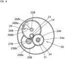
- FIG. 8 is a planar view of a cross-section taken at line B-B of the flow rate control valve 1B illustrated in FIG. 7
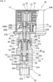
- FIG. 9 is a longitudinal cross-sectional view illustrating a valve opened state of the flow rate control valve 1B according to the second embodiment
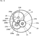
- FIG. 10 is a planar view of a cross-section similar to FIG. 8 of the flow rate control valve illustrated in FIG. 9
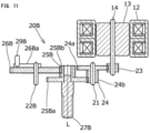
- FIG. 11 is a view illustrating a gear train adopted in the flow rate control valve 1B in expansion such that axis lines of the respective gears are positioned within a same plane, with a portion thereof simplified.
- the flow rate control valve 1B includes a driving unit 10B, a reduction unit 20B, and the valve mechanism unit 30. Also, according to the present embodiment, an axis line of the valve mechanism unit 30 is denoted as L. A side on which a motor is disposed is referred to as an upper side, and a side on which a valve element is disposed is referred to as a lower side.
- the driving unit 10B includes a support cylinder 16B. On a lower surface of a top part of the support cylinder 16B, a fixed shaft 16Ba is formed coaxially with the axis line L. An annular member 17B does not have a pin disposed thereon. Instead, a pin 29B is provided downward at a position spaced apart from the axis line L on the lower surface of the support cylinder 16B.
- the reduction unit 20B includes the first shaft 21 and an idling shaft 22B each having both ends thereof retained by a lower surface of the top part of the support cylinder 16B and an upper surface of the annular member 17B, the drive gear 23 fixed to a lower end of the drive shaft 14, the first transmission gear 24 retained rotatably with respect to the first shaft 21, a final gear 25B retained rotatably with respect to the fixed shaft 16Ba and connected coaxially with a screw shaft 27B, and an idle gear 26B connected coaxially with the idling shaft 22B and meshing with the final gear 25B.
- the final gear 25B constitutes a rotating body. Components that are common with the above-mentioned embodiment are denoted with the same reference numbers, and descriptions thereof are omitted.
- a protruded portion 26Ba is formed on an upper surface of the idle gear 26B.
- the protruded portion 26Ba is formed in a narrow fan shape when viewed in the direction of the axis line L, as illustrated in FIGs. 8 and 10 .
- One end surface of the protruded portion 26Ba facing the circumferential direction is referred to as an end surface 26Bb, and the other surface thereof is referred to as an end surface 26Bc.
- the angle from the end surface 26Bb to the end surface 26Bc is set to a predetermined value.
- the first transmission gear 24 is formed by coaxially connecting the first input gear portion 24a meshing with the drive gear 23 and the first output gear portion 24b.
- the final gear 25B is formed by coaxially connecting an input gear portion 25Ba meshing with the first output gear portion 24b and an output gear portion 25Bb meshing with the idle gear 26B.
- the flow rate control valve 1B in a state where the male screw shaft 27B rotates for a predetermined angle after the valve element 33 had been seated, the end surface 26Bb (first engagement portion) of the protruded portion 26Ba of the idle gear 26B comes into contact with the pin 29 (second engagement portion) such that further rotation of the final gear 25B is prevented.
- the pin 29 (second engagement portion) and the end surface 26Bb (first engagement portion) respectively function as a lower limit-side stopper of the valve element.
- the number of teeth ZA of the drive gear 23 is smaller than the number of teeth ZB of the first input gear portion 24a. Further, a number of teeth ZG of the input gear portion 25Ba of the final gear 25B is smaller than the number of teeth ZC of the first output gear portion 24b. Therefore, while the rotational force is transmitted from the drive gear 23 to the final gear 25B, reduction at a reduction ratio of (ZB/ZA) ⁇ (ZC/ZG) is realized.
- a rotation angle of the idle gear 26B increases with respect to the rotation angle of the final gear 25B, such that a timing at which the pin 29 comes into contact with the end surface 26Bb can be set with higher accuracy. Further, an amount of lift of the valve element 33 with respect to a rotation angle of the drive gear 23 can be increased without changing the timing at which the pin 29 comes into contact with the end surface 26Bb. Thereby, pressure loss during fully-opened state of the valve can be reduced, such that the orifice diameter can be reduced and load of differential pressure can be expected to be reduced.
- FIG. 12 is a longitudinal cross-sectional view illustrating a valve closed state of a flow rate control valve 1C according to a third embodiment
- FIG. 13 is a longitudinal cross-sectional view illustrating a valve opened state of the flow rate control valve 1C according to the third embodiment, wherein the stator is not shown.
- FIG. 14 is a view showing a planetary gear mechanism in an exploded state.
- FIG. 15 is a perspective view illustrating a lower surface of a gear body 125 and an upper surface of a female screw cylinder 128.
- the flow rate control valve 1C includes a driving unit 110, a planetary gear-type reduction mechanism (hereinafter referred to as "reduction unit") 120 to which rotational force by the driving unit 110 is entered and gear reduction is performed, and a valve mechanism unit 130.
- An axis line of the flow rate control valve 1C is referred to as L.
- a motor side is referred to as an upper side
- a valve element side is referred to as a lower side.
- a can 111 arranged on an inner side in a radial direction of a stator not shown in the drawing is an airtight container having a lower end thereof fixed to a valve body 131 via an annular receiving member 112, and it is formed in the shape of a thin cylinder with a top part.
- the driving unit 110 includes a permanent magnet-type rotor assembly 113 that is driven to rotate by a stator not shown.
- the rotor assembly 113 is rotatably supported within the can 111.
- a stepping motor serving as an example of an electric motor is composed of a stator and the rotor assembly 113.
- the reduction unit 120 includes, as illustrated in FIG. 14 , a sun gear 121 formed integrally with the rotor assembly 113, a plurality of (three according to the present embodiment) planetary gears 123 that are elongated in the axial direction that mesh with the sun gear 121 and that are supported rotatably by a carrier 122 formed by molding plastic, a ring gear 124 that is arranged coaxially with the sun gear and that meshes with one portion (upper side portion) of each planetary gear 123, and a gear body 125 equipped with an output gear portion 125a with internal teeth whose number of teeth slightly differs from the number of teeth of the ring gear 124 (in other words, that is in a profile shift relationship with the ring gear 124). It is preferable for the sun gear 121, the carrier 122, the ring gear 124, and the gear body 125 to be formed of PPS (polyphenylene sulfide resin).
- the gear body 125 constitutes a rotating body.
- each planetary gear 123 meshes with the ring gear 124 and also meshes with the output gear portion 125a of the gear body 125 at one portion (lower side portion) thereof.
- the sun gear 121 is formed on an outer circumference of a cylinder installed at a center of the sun gear member 127.
- the ring gear 124 is a ring-shaped gear formed by molding plastic, for example.
- the planetary gears 123 meshing with the sun gear 121 and the ring gear 124 rotate while revolving around the sun gear 121. Since the planetary gear 123 meshes with the gear body 125 which is in a profile-shifted relationship with the ring gear 124, the gear body 125 rotates at a relatively extremely high reduction ratio, such as 50 to 1, with respect to the ring gear 124 according to the level of profile shift (difference between number of teeth).
- a planetary gear mechanism in which the planetary gears 123 are meshed with the ring gear 124 and the output gear portion 125a in a profile-shifted relationship is referred to as a paradox planetary gear mechanism.
- the carrier 122 includes a lower side disk 122b formed by installing three pillar portions 122a in parallel on the outer circumference of the upper surface, an annular plate 122c, and a cylindrical carrier shaft portion 122d that extends downward from a center of the lower side disk 122b, and wherein the lower side disk 122b and the plate 122c are fixed in parallel via the pillar portions 122a.
- a fitting hole 122e to which a lower end of the shaft 144 is rotatably fit is coaxially formed on an upper end side of the carrier shaft portion 122d, and an engaging hole 122f is coaxially formed on a lower end side thereof.
- the engaging hole 122f has a cross-sectional surface orthogonal to the axis line L with a noncircular shape, such as a D-shape.
- the female screw cylinder 128 is arranged below the carrier 122.
- the female screw cylinder 128 is fixed and connected to an upper end of the valve body 131 via an annular plate 132.
- the female screw cylinder 128 is made of resin having superior sliding characteristics, such as a PTFE (polytetrafluoroethylene), and the annular plate 132 made of metal is fixed near an upper end thereof through insert molding, for example.
- the female screw cylinder 128 includes a cylindrical opening 128a formed at a center of an upper end thereof, a female screw portion 128b communicated with the opening 128a, and a thin cylinder portion 128c formed on a lower end side.
- the carrier shaft portion 122d is relatively rotatably fit to the opening 128a.
- the rotation axis of the gear body 125 is fixed, and the rotation of the respective gears are stabilized. Further, by providing the projected portion 125c at a position close to and in the same direction as the guide arranged below the output gear portion 125a, load will not easily occur in the direction intersecting the rotation axis of the gear when the projected portion 125c comes into contact with the stepped portion 128g, such that wear of the gear can be reduced.
- the first to fourth engagement portions will be described below.
- the projected portion 125c is formed on the lower surface of the gear body 125 and the locking portion 128e (the stepped portion 128g) is formed on the upper surface of the female screw cylinder 128, but of course, the projected portion 125c can be formed on the upper surface of the gear body 125 and the locking portion 128e (the stepped portion 128g) can be formed on the lower surface of the ring gear 124. In that case, by guiding the outer circumference of the gear body 125 and the inner circumference of a gear case 141, load will not easily occur in the direction intersecting the rotation axis of the gear, such that wear of the gear can be reduced. Of course, it is possible to form the projected portion 125c on a side face of the gear body 125 and to arrange the locking portion 128e accordingly.
- a male screw member 129 inserted to the female screw cylinder 128 is formed by consecutively connecting an engagement portion 129a, a male screw portion 129b, and a disk portion 129c.
- the engagement portion 129a has a cross section orthogonal to the axis line L formed in a noncircular shape, similar to the engaging hole 122f, and it is capable of moving relatively in the axial direction with respect to the engaging hole 122f in a state engaged with the engaging hole 122f, but it rotates integrally therewith in the rotation direction.
- the male screw portion 129b is engaged with the female screw portion 128b.
- the male screw member 129 constitutes a moving body.
- the disk portion 129c is arranged within the thin cylinder portion 128c of the female screw cylinder 128.
- a communicating hole 128d is formed on a peripheral wall of the thin cylinder portion 128c.
- valve mechanism unit 130 Next, the valve mechanism unit 130 will be described.
- the valve body 131 formed of metal has a relatively thick hollow cylindrical shape, and as described above, the lower end of the can 111 is fixed thereto via the receiving member 112 having an annular shape, and the outer circumference of the upper end of the valve body 131 and the outer circumference of the ring gear 124 are connected by the gear case 141 which is a thin cylindrical member.
- a communicating hole 131a is formed to the peripheral wall between the gear case 141 and the receiving member 112.
- the inner side of the valve body 131 constitutes the valve chamber C.
- the first piping 51 constituting a first flow path in a manner orthogonal to the axis line L is connected to an opening 131c formed to an outer circumference in the vicinity of the lower end of the valve body 131.
- the axis line of the first piping 51 is referred to as O.
- an opening formed coaxially with the axis line L at the lower end of the valve body 131 constitutes an orifice 131d. Further, an upper end of the orifice 131d constitutes a valve seat 131e.
- the second piping 52 is connected to the valve body 131 in a manner communicating with the orifice 131d.
- a sleeve member 133 having a bottomed cylinder shape is arranged on a lower side of the male screw member 129.
- the sleeve member 133 is formed by consecutively connecting a cylinder portion 133a fit slidably to an inner circumference of the thin cylinder portion 128c, and a bottom portion 133c.
- a communicating hole 133b is formed to a peripheral wall of the cylinder portion 133a.
- An upper end of the cylinder portion 133a is fixed by caulking to an outer circumference of the disk portion 129c of the male screw member 129, such that the sleeve member 133 and the male screw member 129 move integrally together.
- the bottom portion 133c includes a circular opening 133d at a center thereof.
- a needle member 134 is formed by consecutively connecting a flange portion 134a and a barrel portion 134b having a smaller diameter than the flange portion 134a.
- a spacer 135 is arranged between the flange portion 134a and the bottom portion 133c of the sleeve member 133.
- the barrel portion 134b is fit to the circular opening 133d in a state where the flange portion 134a is arranged within the sleeve member 133, a lower end side of the barrel portion 134b protrudes from the sleeve member 133, but since the flange portion 134a is caught by the edge of the circular opening 133d, the needle member 134 will not fall from the sleeve member 133.
- a cylindrical holder 136 is arranged on an upper side of the flange portion 134a of the needle member 134.
- the holder 136 is formed by consecutively connecting a circular flange portion 136a and a cylinder portion 136b.
- a coil spring 139 is arranged on an outer side of the cylinder portion 136b with a lower end thereof in contact with an upper surface of the circular flange portion 136a.
- An upper end of the coil spring 139 serving as an urging member is in contact with a lower surface of the disk portion 129c. Therefore, the needle member 134 is constantly urged downward with respect to the male screw member 129 via the holder 136 by the coil spring 139.
- a valve element 137 having an annular shape is press-fit to an outer circumference of the barrel portion 134b projected downward from the sleeve member 133.
- An outer circumference surface of the valve element 137 is formed in a conical shape that is reduced in diameter toward the lower side.
- the lower end of the needle member 134 can also adopt a conical shape.
- a predetermined gap is formed between a lower surface of the sleeve member 133 and an upper surface of the valve element 137, and the sleeve member 133 and the needle member 134 can be relatively displaced in the axial direction corresponding to the gap. This gap can be adjusted by changing the thickness of the spacer 135.
- the first piping 51 and the second piping 52 are connected to a refrigeration cycle, wherein the first piping 51 serves as an inlet-side piping and the second piping 52 serves as an outlet-side piping.
- the male screw member 129 rotates along with the rotation of the gear body 125.
- a rotary motion of the male screw member 129 is converted into an axial direction movement via a conversion mechanism, and thereby, the male screw member 129 is displaced downward with respect to the gear body 125.
- the sleeve member 133, the holder 136, the needle member 134 and the valve element 137 are also displaced downward.
- the projected portion 125c also relatively moves along the outer circumference of the guide portion 128f and approximates the stepped portion 128g.
- the projected portion 125c comes into contact with the stepped portion 128g (second engagement portion) of the guide portion 128f before the gap between the lower surface of the sleeve member 133 and the upper surface of the valve element 137 becomes zero, such that further rotation and lowering of the male screw member 129 is prevented. That is, the projected portion 125c (first engagement portion) and the stepped portion 128g (second engagement portion) respectively function as a lower limit-side stopper of the valve element.
- the only pressing force applied to the valve element 137 is the urging force of the coil spring 139, such that excessive increase of pressing force generated between the valve element 137 and the valve seat 131e can be prevented.
- the pressing force is relatively low, indentation will not occur, so that if the foreign matter drops out when the valve is opened for the next time, a good sealing efficiency between the valve element 137 and the valve seat 131e can be ensured.
- the male screw member 129 rotates along with the rotation of the gear body 125. Rotary motion of the male screw member 129 is converted into axial direction movement via a conversion mechanism, and thereby, the male screw member 129 is displaced upward with respect to the gear body 125. In a state where the male screw member 129 is displaced upward, the sleeve member 133, the holder 136, the needle member 134, and the valve element 137 are also displaced upward. In this state, the projected portion 125c also moves relatively along the outer circumference of the guide portion 128f.
- the projected portion 125c (third engagement portion) comes into contact with the stepped portion 128h (fourth engagement portion) of the guide portion 128f, such that further rotation and elevation of the male screw member 129 is prevented. That is, the projected portion 125c (third engagement portion) and the stepped portion 128h (fourth engagement portion) respectively function as an upper limit-side stopper of the valve element.
- FIG. 16 is a longitudinal cross-sectional view illustrating a valve closed state of a flow rate control valve 1D according to a fourth embodiment, similarly with the stator omitted.
- the present embodiment mainly differs from the third embodiment in that the shapes of a gear body 125D and a female screw cylinder 128D are different, and that a carrier 122D and a shaft portion 122Dd are separated. Components common to the embodiments described above are denoted with the same reference numbers, and descriptions thereof are omitted.
- the gear body 125D serving as a rotating body includes an annular portion 125De protruded upward from a circumference of an upper end at a center bottom opening 125Db.
- a disk-shaped carrier 122D is slidably arranged on the upper surface of the annular portion 125De.
- the female screw cylinder 128D does not have a thin cylinder portion, and an upper end surface thereof faces a lower surface of the gear body 125D.
- An upper end portion 122Dh reduced in diameter of the shaft portion 122Dd is press-fit to an inner circumference of the bottom opening 125Db of the gear body 125D, and a lower end side of the shaft portion 122Dd is slidably fit to an opening 128Da of the female screw cylinder 128D.
- An upper end surface of the shaft portion 122Dd is arranged to face a lower surface of the carrier 122D.
- the engagement portion 129a of the male screw member 129 is fit to an engagement hole 122Df of the shaft portion 122Dd.
- a lower end of the shaft 114 passes through a center opening of the carrier 122D and is relatively rotatably fit to a fitting hole 122De of the shaft portion 122Dd.
- the gear body 125D and the shaft portion 122Dd are rotated integrally. Therefore, the male screw member 129 rotates simultaneously via the engagement of the engagement hole 122Df and the engagement portion 129a. Thereby, relative screw motion of a female screw portion 128Db and the male screw portion 129b is realized, and the valve element 137 is displaced in the direction of the axis line L.
- the gear body 125D is a gear that is reduced most by the reduction unit 120, but in the present configuration, the rotation angle in which the gear body 125D is allowed to rotate is small (such as less than 360 degrees) so that in the present embodiment, a screw pitch of the female screw portion 128Db and the male screw portion 129b is made relatively large so as to ensure the required amount of lift of the valve element 137.
- a means for ensuring the amount of list includes adopting a multiple thread screw (such as a double-thread screw) as the female screw portion 128Db and the male screw portion 129b. Adopting such a multiple thread screw is effective, since if the screw diameter is small, the stiffness of the screw may be insufficient by merely increasing the screw pitch.
- a multiple thread screw such as a double-thread screw
- a projected portion 125Dc is formed on a lower surface of the gear body 125D at a position spaced apart from the axis line. Similar to the embodiment described above, by providing the projected portion 125Dc at a position close to an upper end of the shaft portion 122Dd, load is not easily generated in a direction orthogonal to the rotation axis of the gear even in a state where the projected portion 125Dc comes into contact with a stepped portion of the female screw cylinder 128D, such that wear of the gear can be reduced.
- the projected portion 125Dc constitutes a first engagement portion and a third engagement portion, and a stepped portion of a guide portion 128Df of the female screw cylinder 128D constitutes a second engagement portion and a fourth engagement portion.
- the present embodiment characterizes in that the rotation angle of the male screw member 129 is small compared to the above-described embodiment. Therefore, a projected portion is provided on the male screw member 129 instead of providing a projected portion on the gear body 125D, and a protruded portion opposed thereto is disposed on the female screw cylinder 128D or the valve body 131, wherein the members are arranged at positions capable of being in contact with one another, such that excessive rotation of the male screw member 129 can be suppressed. In that case, the male screw member 129 constitutes the rotating body and the moving body.
Landscapes
- Engineering & Computer Science (AREA)
- General Engineering & Computer Science (AREA)
- Mechanical Engineering (AREA)
- Physics & Mathematics (AREA)
- Fluid Mechanics (AREA)
- Electrically Driven Valve-Operating Means (AREA)
Abstract
Description
- The present invention relates to a flow rate control valve.
- For example, refrigeration cycles adopted in room air conditioners and car air conditioners are equipped with a flow rate control valve for controlling the flow rate of a refrigerant, in addition to a compressor, an outdoor heat exchanger, an indoor heat exchanger, an expansion valve, etc.
- A gear type motor-operated valve disclosed in
Patent Literature 1 is known as one example of such a flow rate control valve. This gear type motor-operated valve reduces a rotational force output from a stepping motor via a reduction mechanism, and further converts the reduced rotational force into an axial direction force using a screw mechanism and transmits the same to a valve element. Thereby, the valve element is separated from or seated on a valve seat, by which valve opening and closing operations are executed. - [PTL 1] Publication of
Japanese Patent Laid-Open Publication No. 2003-232465 - In the gear type motor-operated valve illustrated in
Patent Literature 1, the rotational force of the stepping motor is reduced by a reduction device, such that a pressing force applied to the valve seat from the valve element when closing the valve is relatively high, and there is an advantage in that a sealing capability when closing the valve can be maintained to a high level. - Meanwhile, there is a risk that foreign matter such as metal may be mixed in the refrigerant being circulated within the refrigeration cycle. If such foreign matter enters the gear type motor-operated valve and is inserted between the valve element and the valve seat when the valve is closed and sandwiched therebetween with strong pressing force, a so-called biting of foreign matter may occur.
- An object of the present invention is to provide a flow rate control valve capable of suppressing foreign matter from being bitten therein and capable of performing appropriate flow rate control.
- In order to achieve the above-mentioned object, a flow rate control valve according to the present invention includes
- a valve body provided with a valve seat;
- a reduction unit configured to reduce and transmit a rotation of a motor to a rotating body;
- a conversion mechanism configured to move a moving body in an axial direction according to a rotational movement of the rotating body; and
- a valve element configured to move according to an axial direction movement of the moving body and move in reciprocating motion with respect to the valve seat;
- wherein a first engagement portion provided on the rotating body and a second engagement portion provided on the valve body are configured to move toward or away from each other according to a rotation of the rotating body, and
- wherein, after the valve element is seated on the valve seat, the first engagement portion and the second engagement portion come into contact with each other, and a rotation of the rotating body is stopped.
- The present invention enables to provide a flow rate control valve capable of suppressing foreign matter from being bitten therein and capable of performing appropriate flow rate control.
-
- [
FIG. 1] FIG. 1 is a longitudinal cross-sectional view illustrating a valve closed state of a flow rate control valve according to a first embodiment. - [
FIG. 2] FIG. 2 is a planar view of a cross-section at line A-A of the flow rate control valve illustrated inFIG. 1 . - [
FIG. 3] FIG. 3 is a longitudinal cross-sectional view illustrating a valve opened state of the flow rate control valve according to the first embodiment. - [
FIG. 4] FIG. 4 is a planar view of a cross-section similar toFIG. 2 of the flow rate control valve illustrated inFIG. 3 - [
FIG. 5] FIG. 5 is a view illustrating a gear train adopted in the flow rate control valve according to the present embodiment in expansion such that axis lines of the respective gears are positioned within a same plane. - [
FIG. 6] FIG. 6 is a cross-sectional view similar toFIG. 5 illustrating a gear train according to a modified example of the present embodiment. - [
FIG. 7] FIG. 7 is a longitudinal cross-sectional view illustrating a valve closed state of a flow rate control valve according to a second embodiment. - [
FIG. 8] FIG. 8 is a planar view of a cross-section at line B-B of the flow rate control valve illustrated inFIG. 7 . - [
FIG. 9] FIG. 9 is a longitudinal cross-sectional view illustrating a valve opened state of the flow rate control valve according to the second embodiment. - [
FIG. 10] FIG. 10 is a planar view of a cross-section similar toFIG. 8 of the flow rate control valve illustrated inFIG. 9 . - [
FIG. 11] FIG. 11 is a view illustrating a gear train adopted in the flow rate control valve according to the present embodiment in expansion such that axis lines of the respective gears are positioned within a same plane. - [
FIG. 12] FIG. 12 is a longitudinal cross-sectional view illustrating a valve closed state of a flow rate control valve according to a third embodiment. - [
FIG. 13] FIG. 13 is a longitudinal cross-sectional view illustrating a valve opened state of the flow rate control valve according to the third embodiment. - [
FIG. 14] FIG. 14 is a view illustrating a planetary gear mechanism in an exploded state. - [
FIG. 15] FIG. 15 is a perspective view illustrating a lower surface of a gear body and an upper surface of a female screw cylinder. - [
FIG. 16] FIG. 16 is a longitudinal cross-sectional view illustrating a valve closed state of a flow rate control valve according to a fourth embodiment. - Now, a flow rate control valve according to an embodiment of the present invention will be described with reference to the drawings. A flow rate control valve according to the present embodiment is disposed within a circulation circuit of a refrigeration cycle apparatus, and it controls a flow rate of refrigerant flowing within the circulation circuit.
-
FIG. 1 is a longitudinal cross-sectional view illustrating a valve closed state of a flowrate control valve 1 according to a first embodiment, andFIG. 2 is a planar view of a cross-section taken at line A-A of the flowrate control valve 1 illustrated inFIG. 1 .FIG. 3 is a longitudinal cross-sectional view illustrating a valve opened state of the flowrate control valve 1 according to the first embodiment, andFIG. 4 is a planar view of a cross-section similar toFIG. 2 of the flow rate control valve illustrated inFIG. 3 .FIG. 5 is a view in which a gear train adopted in the flowrate control valve 1 is illustrated in expansion such that the axis lines of the respective gears are positioned within the same plane, but with a portion thereof simplified. - The flow
rate control valve 1 includes adriving unit 10, areduction unit 20, and avalve mechanism unit 30. An axis line of thevalve mechanism unit 30 is denoted as L. In the description, a side on which a motor is arranged is referred to as an upper side, and a side on which a valve element is arranged is referred to as a lower side. - At first, the
driving unit 10 will be described. In the drawing, thedriving unit 10 includes adriving unit case 11, astator 12 attached to an inner side of thedriving unit case 11, arotor 13 arranged on an inner side in a radial direction of thestator 12, and adrive shaft 14 fixed to therotor 13. Thestator 12 and therotor 13 constitute a stepping motor. The driving source is not limited to the stepping motor, and it can be a brushless motor or a motor with a brush. - The
driving unit case 11 is formed in the shape of a cylinder with a top part, and abearing 15 is fixed to a lower surface at a center of the top part. Thebearing 15 retains thedrive shaft 14 rotatably. Asupport cylinder 16 formed in the shape of a cylinder with a top part is disposed so as to fit to an inner circumference of thedriving unit case 11 at a lower side of thestator 12 and therotor 13. A lower end of thesupport cylinder 16 is in contact with an upper surface of anannular member 17 sealing thedriving unit case 11, and the lower end of thedriving unit case 11 and an outer circumference of theannular member 17 are fixed by caulking. - The
support cylinder 16 includes ahollow cylinder portion 16a formed on a lower surface at a center of the top part, and a through hole (not shown). A lower end of thedrive shaft 14 passes through the through hole of thesupport cylinder 16 and is rotatably supported in the through hole. - Next, the
reduction unit 20 will be described. - The
reduction unit 20 includes afirst shaft 21 and asecond shaft 22 each having both ends thereof retained by a lower surface of the top part of thesupport cylinder 16 and an upper surface of theannular member 17, adrive gear 23 fixed to a lower end of thedrive shaft 14 passing through the through hole of thesupport cylinder 16, afirst transmission gear 24 retained rotatably with respect to thefirst shaft 21, asecond transmission gear 25 retained rotatably with respect to thesecond shaft 22, afinal gear 26, amale screw shaft 27, and afemale screw cylinder 28. Thefinal gear 26 constitutes a rotating body, and themale screw shaft 27 constitutes a moving body. Themale screw shaft 27 is press-fit to and integrated with thefinal gear 26. - The
first shaft 21 and thesecond shaft 22 are arranged in parallel with thedrive shaft 14. As illustrated inFIG. 5 , thefirst transmission gear 24 is formed by connecting a firstinput gear portion 24a meshing with thedrive gear 23 and a firstoutput gear portion 24b coaxially. Thesecond transmission gear 25 is formed by connecting a secondinput gear portion 25a meshing with the firstoutput gear portion 24b and a secondoutput gear portion 25b meshing with thefinal gear 26 coaxially. The respective shafts can be formed of metal and the respective gears can be formed of resin. Thedrive gear 23, thefirst transmission gear 24, thesecond transmission gear 25, and thefinal gear 26 constitute a gear train. - A number of teeth ZA of the
drive gear 23 is smaller than a number of teeth ZB of the firstinput gear portion 24a. A number of teeth ZC of the firstoutput gear portion 24b is smaller than a number of teeth ZD of the secondinput gear portion 25a. Further, a number of teeth ZE of the secondoutput gear portion 25b is smaller than a number of teeth ZF of thefinal gear 26. Therefore, while the rotational force is transmitted from thedrive gear 23 to thefinal gear 26, reduction at a reduction ratio of (ZB/ZA) × (ZD/ZC) × (ZF/ZE) is realized. - With reference to
FIGs. 2 and4 , thefinal gear 26 includes an arc-shapedgroove 26a formed on a lower surface thereof so as to surround themale screw shaft 27. One end in a circumferential direction of the arc-shapedgroove 26a is referred to as anend portion 26b, and the other end thereof is referred to as anend portion 26c. An angle from theend portion 26b to theend portion 26c is set to a predetermined value. Theend portion 26b constitutes a first engagement portion, and theend portion 26c constitutes a third engagement portion. The first engagement portion and the third engagement portion will be described later. As described above, thefinal gear 26 constitutes a rotating body, but the rotating body is not limited to thefinal gear 26. For example, any member that rotates by receiving rotational force from therotor 13 and that includes at least a first engagement portion that moves toward or away from a second engagement portion of avalve body 31 according to rotation can be adopted as the rotating body. - In
FIGs. 1 and2 , ahole 17a is formed on an upper surface of theannular member 17, and a lower end of apin 29 is fit and fixed to thehole 17a. Further, an upper end of thepin 29 is arranged to be positioned within the arc-shapedgroove 26a. Thepin 29 constitutes a second engagement portion and a fourth engagement portion arranged on thevalve body 31. "Arranged on thevalve body 31" refers not only to a state being directly arranged on thevalve body 31 but also to a state indirectly arranged on another member fixed to thevalve body 31. The second engagement portion and the fourth engagement portion will be described later. - The
male screw shaft 27 is arranged such that the upper end thereof is fit to aninner circumference 16b of thehollow cylinder portion 16a of thesupport cylinder 16, and it is arranged in a manner capable of being relatively rotated and displaced in an axial direction within thehollow cylinder portion 16a. Further, thefinal gear 26 is fit and fixed at an intermediate position of themale screw shaft 27, and amale screw 27a is formed on an outer circumference of a lower end side of themale screw shaft 27. - The
female screw cylinder 28 having a hollow cylindrical shape is fit and fixed to an inner circumference to theannular member 17 at an upper end side that is reduced in diameter, and includes a throughhole 28a formed to pass through along an axis line L. Afemale screw 28b engaged with themale screw 27a is formed to a lower end side of the throughhole 28a. Thefemale screw cylinder 28 is fixed to theannular member 17, such that when themale screw shaft 27 rotates, themale screw 27a is moved in screwing motion with respect to thefemale screw 28b, and thereby, an axial direction force is applied from thefemale screw cylinder 28. Thereby, themale screw shaft 27 is displaced in an axial direction for an amount corresponding to its own rotation angle. Themale screw shaft 27 and thefemale screw cylinder 28 constitute a conversion mechanism. - The
female screw cylinder 28 includes athin cylinder portion 28c enlarged in diameter on a lower end thereof. Further, acylindrical coupling member 34 is arranged on an outer circumference of thefemale screw cylinder 28. Thecoupling member 34 includes anupper end portion 34a that is reduced in diameter fit to the outer circumference of thefemale screw cylinder 28, and aninternal screw portion 34b on an inner circumference of the lower end thereof. - Next, the
valve mechanism unit 30 will be described. - The
valve mechanism unit 30 includes thevalve body 31, avalve stem 32, and avalve element 33. - The
valve body 31 made of metal has a relatively thick hollow cylindrical shape, including a reduceddiameter portion 31a on an outer circumference at an upper end thereof, and anoutside screw portion 31b on the outer circumference at a lower side of the reduceddiameter portion 31a. Thethin cylinder portion 28c fits to the outer circumference of the reduceddiameter portion 31a. By screwing theinternal screw portion 34b of thecoupling member 34 fit to the outer circumference of thefemale screw cylinder 28 to theoutside screw portion 31b and engaging thecoupling member 34, the lower surface of theupper end portion 34a being reduced in diameter comes into contact with and fits to a stepped portion at an upper end of thethin cylinder portion 28c. Thereby, thefemale screw cylinder 28 can be coupled and fixed to thevalve body 31. - A
spacer 35 is arranged between a lower surface of thefemale screw cylinder 28 at an inner circumference of thethin cylinder portion 28c and an upper end of thevalve body 31, by which a distance between thevalve body 31 and thefemale screw cylinder 28 when coupling and fixing the members can be adjusted. - A
first piping 51 forming a first flow path arranged orthogonal to the axis line L is connected to anopening 31c formed to an outer circumference in the vicinity of the lower end of thevalve body 31. An axis line of thefirst piping 51 is referred to as O. - An opening formed coaxially with the axis line L at a lower end of the
valve body 31 constitutes anorifice 31d. Further, an upper end of theorifice 31d constitutes avalve seat 31e. Asecond piping 52 is connected to thevalve body 31 so as to pass through theorifice 31d. - The valve stem 32 is arranged on an inner side of the
valve body 31. The valve stem 32 is formed by asmall diameter portion 32a, alarge diameter portion 32b, aflange portion 32c, and a small-diameter protrudedportion 32d, which are coaxially consecutively connected. Aball retaining portion 32e which is formed as a separate member as thevalve stem 32 is attached to an upper end of thesmall diameter portion 32a facing a lower end of themale screw shaft 27. Aball 37 made of metal is arranged between a recessed portion at a center of a lower end of themale screw shaft 27 and a recessed portion at a center of an upper end of theball retaining portion 32e. - An
annular plate 36 is fixed by caulking to the inner circumference of the upper end of thevalve body 31. A bellows 38 made of metal connects the lower surface of theannular plate 36 and the outer circumference of the upper end of thelarge diameter portion 32b of thevalve stem 32 in a manner covering thesmall diameter portion 32a of thevalve stem 32. Therefore, during use of the flowrate control valve 1, an outer side of thebellows 38 will be in contact with the refrigerant at the inner side of thevalve body 31, and an inner side of thebellows 38 will be in contact with air. The outer side of thebellows 38 in the interior of thevalve body 31 constitutes a valve chamber C. - The
valve element 33 having a bottomed cylinder shape is arranged at a lower side of thevalve stem 32. Thevalve element 33 is formed by alarge cylinder portion 33a on an upper end side that is movable in sliding motion against the inner circumference of thevalve body 31, asmall cylinder portion 33b on a lower end side, and abottom portion 33c, which are consecutively connected. Atapered surface 33d that is axisymmetric to the axis line L is formed on a lower surface side of thebottom portion 33c. An upper end of thelarge cylinder portion 33a is fixed by caulking to the outer circumference of anannular slide plate 40. Theslide plate 40 is fit slidably along the direction of axis line L to thelarge diameter portion 32b of thevalve stem 32, and it is prevented from moving further toward the lower side of thevalve stem 32 by coming into contact with theflange portion 32c. Thevalve stem 32 and thevalve element 33 are relatively displaceable for a predetermined distance in the axial direction. - A
coil spring 39 serving as an urging member is arranged on an inner circumference side of thesmall cylinder portion 33b of thevalve element 33. An upper end of thecoil spring 39 comes into contact with a lower end of thevalve stem 32 in a circumference of the small-diameter protrudedportion 32d, and a lower end of thecoil spring 39 comes into contact with an upper surface of thebottom portion 33c of thevalve element 33. Therefore, thevalve element 33 is constantly urged downward with respect to thevalve stem 32 by thecoil spring 39. Themale screw shaft 27 can also be formed integrally with thevalve stem 32 and thevalve element 33. - An operation of the flow
rate control valve 1 according to the present embodiment will be described. Thefirst piping 51 and thesecond piping 52 are connected to the refrigeration cycle, wherein thefirst piping 51 serves as an inlet-side piping and thesecond piping 52 serves as an outlet-side piping. - In a valve opened state, when power is supplied from an external power supply to the driving
unit 10 according to a control signal and thedrive shaft 14 rotates in one direction, the rotary motion is reduced through the gear train of thereduction unit 20 and transmitted to themale screw shaft 27. The rotary motion transmitted to themale screw shaft 27 is converted via a conversion mechanism of thereduction unit 20 into an axial direction movement, by which themale screw shaft 27 is displaced downward together with thefinal gear 26, that is, themale screw shaft 27 is moved toward the lower side in the axial direction according to the rotation of thefinal gear 26. Even in a case where thefinal gear 26 is displaced in the axial direction, the meshing thereof with thesecond transmission gear 25 will not be disengaged. - When the
male screw shaft 27 is displaced downward, thevalve stem 32 moves downward by being pressed via theball 37. In a state where thevalve stem 32 moves downward, thebellows 38 expands, thevalve element 33 moves downward in a state being pressed by thecoil spring 39, and the taperedsurface 33d is seated on thevalve seat 31e. In this state, thecoil spring 39 exerts a shock absorbing effect of weakening the shock of seating. - Further, by the rotation of the
valve stem 32, thevalve stem 32 is lowered and thecoil spring 39 is compressed, by which the taperedsurface 33d is pressed against thevalve seat 31e with a predetermined urging force. In this state, theslide plate 40 moves in sliding motion along the outer circumference of thelarge diameter portion 32b of thevalve stem 32, allowing thevalve stem 32 and thevalve element 33 to be relatively displaced against the urging force of thecoil spring 39. As described above, since a predetermined preload is applied and the valve closed state is ensured, the flow of refrigerant from thefirst piping 51 through the valve chamber C toward thesecond piping 52 is cutoff. This state is illustrated inFIG. 1 . - Further during this state, fluid pressure within the valve chamber C acts on the outer surface of the
bellows 38, such that if fluid pressure of a predetermined value or greater acts thereon, thebellows 38 is acted in the expanding direction, and thevalve element 33 can be moved in the opening direction together with thevalve stem 32. - The rotational force output from the driving
unit 10 is reduced by thereduction unit 20, and therefore, the force in which themale screw shaft 27 and thevalve stem 32 are moved in the axial direction is increased. Therefore, when the rotational force from the drivingunit 10 is applied further in a state where the bottom of thevalve stem 32 is in contact with thevalve element 33, the pressing force generated between thetapered surface 33d and thevalve seat 31e becomes excessive. - In the present embodiment, a structure is provided to suppress the pressing force generated between the
tapered surface 33d and thevalve seat 31e from becoming excessive. Specifically, in a state where thefinal gear 26 rotates together with themale screw shaft 27, thepin 29 moves relatively along the arc-shapedgroove 26a, and thepin 29 approximates theend portion 26b. Further, after the taperedsurface 33d is seated on thevalve seat 31e, in a state where themale screw shaft 27 rotates for a predetermined angle, the pin 29 (second engagement portion) comes into contact with theend portion 26b (first engagement portion) of the arc-shapedgroove 26a, such that further rotation of thefinal gear 26 is prevented, and the valve stem (valve element) will not be lowered further. Such a state is illustrated inFIG. 2 . That is, the pin 29 (second engagement portion) and theend portion 26b (first engagement portion) respectively function as a lower limit-side stopper of the valve element. - Since the lowering of the
male screw shaft 27 and thevalve stem 32 is stopped thereby, the pressing force applied to thevalve element 33 with respect to thevalve stem 32 will only be the urging force of thecoil spring 39, such that excessive increase of pressing force generated between thetapered surface 33d and thevalve seat 31e can be avoided. In this state, even if a foreign matter is bitten between thetapered surface 33d and thevalve seat 31e, indentation will not occur since the pressing force is relatively small, such that if the foreign matter drops out when the valve is opened for the next time, a good sealing efficiency between thetapered surface 33d and thevalve seat 31e can be ensured. - Meanwhile, in a state where the
drive shaft 14 rotates in an opposite direction by power fed from an external power supply according to a control signal of reverse characteristics, the force is reduced through the gear train of thereduction unit 20 and transmitted to themale screw shaft 27. The rotary motion transmitted to themale screw shaft 27 is converted into an axial direction movement through the conversion mechanism of thereduction unit 20, and thereby, themale screw shaft 27 is displaced upward together with thefinal gear 26. - In a state where the
male screw shaft 27 is displaced upward, the force pressing thevalve stem 32 toward the valve closing direction is eliminated, such that thebellows 38 receiving refrigerant pressure within the valve chamber C expands and thevalve stem 32 elevates. In a state where thevalve stem 32 elevates, theslide plate 40 is locked by theflange portion 32c of thevalve stem 32, and thereafter, thevalve element 33 elevates together with thevalve stem 32, such that the taperedsurface 33d separates from thevalve seat 31e. Such a state is illustrated inFIG. 3 . - In this state, the refrigerant entering the valve chamber C from the first piping 51 passes through a gap formed between the
tapered surface 33d and thevalve seat 31e, and flows out through theorifice 31d into thesecond piping 52. Since the gap between thetapered surface 33d and thevalve seat 31e changes according to the rotation angle of thedrive shaft 14, by adjusting the rotation angle of thedrive shaft 14, the amount of refrigerant flowing from thefirst piping 51 to thesecond piping 52 can be adjusted. - According further to the present embodiment, even if the
drive shaft 14 rotates excessively to the opposite direction due to a step-out phenomenon, for example, the pin 29 (fourth engagement portion) comes into contact with theend portion 26c (third engagement portion) at the opposite side of the arc-shapedgroove 26a, such that further rotation of thefinal gear 26 is prevented, and the valve stem (valve element) will not elevate further. Such a state is illustrated inFIG. 4 . That is, the pin 29 (fourth engagement portion) and theend portion 26c (third engagement portion) respectively function as an upper limit-side stopper of the valve element. -
FIG. 6 is a cross-sectional view similar toFIG. 5 illustrating a gear train according to a modified example of the present embodiment. Areduction unit 20A according to the present modified example also includes thefirst shaft 21, thesecond shaft 22, thedrive gear 23, thefirst transmission gear 24, thesecond transmission gear 25, afinal gear 26A, and themale screw shaft 27. Components common to the embodiments described above are denoted with the same reference numbers, and descriptions thereof are omitted. - In the present modified example, unlike the embodiment described above, an arc-shaped groove is not disposed on a lower surface of the
final gear 26A, and instead, a projection 26Aa is formed at a position distant from the axis line L on a lower surface. The projection 26Aa constitutes a first engagement portion. - Similar to the embodiment described above, the
final gear 26A moves up and down together with themale screw shaft 27 according to rotation, such that the projection 26Aa descends in screw motion around the axis line L in a state where thevalve element 33 moves from the valve opened state toward the valve closing direction. Therefore, by adjusting a height H of the projection 26Aa in advance, the projection 26Aa can be caused to pass through (not come into contact with) the upper part of the pin 29 (second engagement portion) on the first turn, and to have the projection 26Aa (first engagement portion) come into contact with thepin 29 for the first time on the second turn (refer toFIG. 5 ), such that further rotation of the output gear is prevented. That is, the pin 29 (second engagement portion) and the projection 26Aa (first engagement portion) can respectively function as a lower limit-side stopper. - According to the present modified example, a freedom of selection of timing of having the projection 26Aa come into contact with the
pin 29 is increased, such that an appropriate reduction ratio of thereduction unit 20A can be selected. Further according to the modified example, since a groove is not formed, thefinal gear 26A can be made thinner, such that the weight of the flow rate control valve can be reduced. - Further, in order to prevent respective end surfaces at the tip of the projection 26Aa and the
pin 29 from coming into contact with each other, it is preferable that the end surfaces at the tip of the projection 26Aa and thepin 29 are not flat, and that they have an inclined surface parallel to the inclination of the screw thread of the male screw (female screw). -
FIG. 7 is a longitudinal cross-sectional view illustrating a valve closed state of a flowrate control valve 1B according to a second embodiment, andFIG. 8 is a planar view of a cross-section taken at line B-B of the flowrate control valve 1B illustrated inFIG. 7 .FIG. 9 is a longitudinal cross-sectional view illustrating a valve opened state of the flowrate control valve 1B according to the second embodiment, andFIG. 10 is a planar view of a cross-section similar toFIG. 8 of the flow rate control valve illustrated inFIG. 9 .FIG. 11 is a view illustrating a gear train adopted in the flowrate control valve 1B in expansion such that axis lines of the respective gears are positioned within a same plane, with a portion thereof simplified. - The flow
rate control valve 1B includes adriving unit 10B, areduction unit 20B, and thevalve mechanism unit 30. Also, according to the present embodiment, an axis line of thevalve mechanism unit 30 is denoted as L. A side on which a motor is disposed is referred to as an upper side, and a side on which a valve element is disposed is referred to as a lower side. - The driving
unit 10B according to the present embodiment includes asupport cylinder 16B. On a lower surface of a top part of thesupport cylinder 16B, a fixed shaft 16Ba is formed coaxially with the axis line L. Anannular member 17B does not have a pin disposed thereon. Instead, apin 29B is provided downward at a position spaced apart from the axis line L on the lower surface of thesupport cylinder 16B. - The
reduction unit 20B includes thefirst shaft 21 and an idlingshaft 22B each having both ends thereof retained by a lower surface of the top part of thesupport cylinder 16B and an upper surface of theannular member 17B, thedrive gear 23 fixed to a lower end of thedrive shaft 14, thefirst transmission gear 24 retained rotatably with respect to thefirst shaft 21, afinal gear 25B retained rotatably with respect to the fixed shaft 16Ba and connected coaxially with ascrew shaft 27B, and anidle gear 26B connected coaxially with the idlingshaft 22B and meshing with thefinal gear 25B. Thefinal gear 25B constitutes a rotating body. Components that are common with the above-mentioned embodiment are denoted with the same reference numbers, and descriptions thereof are omitted. - A protruded portion 26Ba is formed on an upper surface of the
idle gear 26B. The protruded portion 26Ba is formed in a narrow fan shape when viewed in the direction of the axis line L, as illustrated inFIGs. 8 and10 . One end surface of the protruded portion 26Ba facing the circumferential direction is referred to as an end surface 26Bb, and the other surface thereof is referred to as an end surface 26Bc. The angle from the end surface 26Bb to the end surface 26Bc is set to a predetermined value. - The
first transmission gear 24 is formed by coaxially connecting the firstinput gear portion 24a meshing with thedrive gear 23 and the firstoutput gear portion 24b. Thefinal gear 25B is formed by coaxially connecting an input gear portion 25Ba meshing with the firstoutput gear portion 24b and an output gear portion 25Bb meshing with theidle gear 26B. - According to the flow
rate control valve 1B, in a state where themale screw shaft 27B rotates for a predetermined angle after thevalve element 33 had been seated, the end surface 26Bb (first engagement portion) of the protruded portion 26Ba of theidle gear 26B comes into contact with the pin 29 (second engagement portion) such that further rotation of thefinal gear 25B is prevented. Such a state is illustrated inFIG. 8 . That is, the pin 29 (second engagement portion) and the end surface 26Bb (first engagement portion) respectively function as a lower limit-side stopper of the valve element. - In contrast, in a state where the
male screw shaft 27B rotates in an opposite direction when opening the valve, the end surface 26Bc (third engagement portion) of the protruded portion 26Ba of theidle gear 26B is in contact with the pin 29 (fourth engagement portion), such that further reverse rotation of thefinal gear 25B is prevented. Such a state is illustrated inFIG. 10 . That is, the pin 29 (fourth engagement portion) and the end surface 26Bc (third engagement portion) respectively function as an upper limit-side stopper of the valve element. - In the present embodiment, the number of teeth ZA of the
drive gear 23 is smaller than the number of teeth ZB of the firstinput gear portion 24a. Further, a number of teeth ZG of the input gear portion 25Ba of thefinal gear 25B is smaller than the number of teeth ZC of the firstoutput gear portion 24b. Therefore, while the rotational force is transmitted from thedrive gear 23 to thefinal gear 25B, reduction at a reduction ratio of (ZB/ZA) × (ZC/ZG) is realized. Meanwhile, since a number of teeth ZH of the output gear portion 25Bb of thefinal gear 25B is smaller than a number of teeth ZI of theidle gear 26B, the rotation of theidle gear 26B is reduced at a reduction ratio of (ZI/ZH) with respect to thefinal gear 25B. - According to the present embodiment, a rotation angle of the
idle gear 26B increases with respect to the rotation angle of thefinal gear 25B, such that a timing at which thepin 29 comes into contact with the end surface 26Bb can be set with higher accuracy. Further, an amount of lift of thevalve element 33 with respect to a rotation angle of thedrive gear 23 can be increased without changing the timing at which thepin 29 comes into contact with the end surface 26Bb. Thereby, pressure loss during fully-opened state of the valve can be reduced, such that the orifice diameter can be reduced and load of differential pressure can be expected to be reduced. -
FIG. 12 is a longitudinal cross-sectional view illustrating a valve closed state of a flowrate control valve 1C according to a third embodiment, andFIG. 13 is a longitudinal cross-sectional view illustrating a valve opened state of the flowrate control valve 1C according to the third embodiment, wherein the stator is not shown.FIG. 14 is a view showing a planetary gear mechanism in an exploded state.FIG. 15 is a perspective view illustrating a lower surface of agear body 125 and an upper surface of afemale screw cylinder 128. - The flow
rate control valve 1C includes adriving unit 110, a planetary gear-type reduction mechanism (hereinafter referred to as "reduction unit") 120 to which rotational force by the drivingunit 110 is entered and gear reduction is performed, and avalve mechanism unit 130. An axis line of the flowrate control valve 1C is referred to as L. Further, a motor side is referred to as an upper side, and a valve element side is referred to as a lower side. - A can 111 arranged on an inner side in a radial direction of a stator not shown in the drawing is an airtight container having a lower end thereof fixed to a
valve body 131 via anannular receiving member 112, and it is formed in the shape of a thin cylinder with a top part. The drivingunit 110 includes a permanent magnet-type rotor assembly 113 that is driven to rotate by a stator not shown. Therotor assembly 113 is rotatably supported within thecan 111. A stepping motor serving as an example of an electric motor is composed of a stator and therotor assembly 113. - The
reduction unit 120 includes, as illustrated inFIG. 14 , asun gear 121 formed integrally with therotor assembly 113, a plurality of (three according to the present embodiment)planetary gears 123 that are elongated in the axial direction that mesh with thesun gear 121 and that are supported rotatably by acarrier 122 formed by molding plastic, aring gear 124 that is arranged coaxially with the sun gear and that meshes with one portion (upper side portion) of eachplanetary gear 123, and agear body 125 equipped with anoutput gear portion 125a with internal teeth whose number of teeth slightly differs from the number of teeth of the ring gear 124 (in other words, that is in a profile shift relationship with the ring gear 124). It is preferable for thesun gear 121, thecarrier 122, thering gear 124, and thegear body 125 to be formed of PPS (polyphenylene sulfide resin). Thegear body 125 constitutes a rotating body. - As can be recognized from
FIG. 14 , eachplanetary gear 123 meshes with thering gear 124 and also meshes with theoutput gear portion 125a of thegear body 125 at one portion (lower side portion) thereof. - The
rotor assembly 113 has abarrel 126 serving as a peripheral wall and asun gear member 127 arranged on a center thereof formed integrally and in the form of a cylinder with a top part formed of a plastic material (PPS according to the present example) containing a magnetic material. Further, therotor assembly 113 is supported rotatably within thecan 111 by a shaft 114 (FIGs. 12 and13 ) that passes through thesun gear member 127 in the axial direction. - As illustrated in
FIG. 14 , thesun gear 121 is formed on an outer circumference of a cylinder installed at a center of thesun gear member 127. Thering gear 124 is a ring-shaped gear formed by molding plastic, for example. - According to this configuration, in a state where the
sun gear 121 rotates on its own axis by the input of rotation from the electric motor, theplanetary gears 123 meshing with thesun gear 121 and thering gear 124 rotate while revolving around thesun gear 121. Since theplanetary gear 123 meshes with thegear body 125 which is in a profile-shifted relationship with thering gear 124, thegear body 125 rotates at a relatively extremely high reduction ratio, such as 50 to 1, with respect to thering gear 124 according to the level of profile shift (difference between number of teeth). A planetary gear mechanism in which theplanetary gears 123 are meshed with thering gear 124 and theoutput gear portion 125a in a profile-shifted relationship is referred to as a paradox planetary gear mechanism. - The
carrier 122 includes alower side disk 122b formed by installing threepillar portions 122a in parallel on the outer circumference of the upper surface, anannular plate 122c, and a cylindricalcarrier shaft portion 122d that extends downward from a center of thelower side disk 122b, and wherein thelower side disk 122b and theplate 122c are fixed in parallel via thepillar portions 122a. Afitting hole 122e to which a lower end of the shaft 144 is rotatably fit is coaxially formed on an upper end side of thecarrier shaft portion 122d, and anengaging hole 122f is coaxially formed on a lower end side thereof. The engaginghole 122f has a cross-sectional surface orthogonal to the axis line L with a noncircular shape, such as a D-shape. - Both ends of each
planetary gear 123 formed of zinc alloy are retained rotatably by thelower side disk 122b and theplate 122c between thepillar portions 122a that are adjacent one another in the circumferential direction, by which theplanetary gear 123 is enabled to rotate with respect to thecarrier 122. - In
FIGs. 12 and13 , thefemale screw cylinder 128 is arranged below thecarrier 122. Thefemale screw cylinder 128 is fixed and connected to an upper end of thevalve body 131 via anannular plate 132. - The
female screw cylinder 128 is made of resin having superior sliding characteristics, such as a PTFE (polytetrafluoroethylene), and theannular plate 132 made of metal is fixed near an upper end thereof through insert molding, for example. Thefemale screw cylinder 128 includes acylindrical opening 128a formed at a center of an upper end thereof, afemale screw portion 128b communicated with theopening 128a, and athin cylinder portion 128c formed on a lower end side. Thecarrier shaft portion 122d is relatively rotatably fit to theopening 128a. - In
FIG. 15 , a projectedportion 125c is formed on a lower surface of thegear body 125 at a position spaced apart from the axis line. Meanwhile, a lockingportion 128e is formed on an upper surface of thefemale screw cylinder 128 below thethin cylinder portion 128c. The lockingportion 128e includes aguide portion 128f having a semi-cylindrical surface shape that extends across a predetermined angle, a steppedportion 128g formed on one end in the circumferential direction of theguide portion 128f, and a steppedportion 128h formed on the other end thereof. The projectedportion 125c constitutes a first engagement portion and a third engagement portion, the steppedportion 128g constitutes a second engagement portion, and the steppedportion 128h constitutes a fourth engagement portion. - By having the
gear body 125 guided by the outer circumference portion of thethin cylinder portion 128c, the rotation axis of thegear body 125 is fixed, and the rotation of the respective gears are stabilized. Further, by providing the projectedportion 125c at a position close to and in the same direction as the guide arranged below theoutput gear portion 125a, load will not easily occur in the direction intersecting the rotation axis of the gear when the projectedportion 125c comes into contact with the steppedportion 128g, such that wear of the gear can be reduced. The first to fourth engagement portions will be described below. - Further according to the present embodiment, the projected
portion 125c is formed on the lower surface of thegear body 125 and the lockingportion 128e (the steppedportion 128g) is formed on the upper surface of thefemale screw cylinder 128, but of course, the projectedportion 125c can be formed on the upper surface of thegear body 125 and the lockingportion 128e (the steppedportion 128g) can be formed on the lower surface of thering gear 124. In that case, by guiding the outer circumference of thegear body 125 and the inner circumference of agear case 141, load will not easily occur in the direction intersecting the rotation axis of the gear, such that wear of the gear can be reduced. Of course, it is possible to form the projectedportion 125c on a side face of thegear body 125 and to arrange the lockingportion 128e accordingly. - In a state where the
thin cylinder portion 128c reduced in diameter of thefemale screw cylinder 128 is fit to abottom opening 125b of thegear body 125 by which thegear body 125 and thefemale screw cylinder 128 are assembled, the upper surface of the lockingportion 128e comes into contact with the lower surface of thegear body 125. In this state, thegear body 125 and thefemale screw cylinder 128 are relatively rotatable, by which the projectedportion 125c moves relatively along the outer circumference of theguide portion 128f. - In
FIGs. 12 and13 , amale screw member 129 inserted to thefemale screw cylinder 128 is formed by consecutively connecting anengagement portion 129a, amale screw portion 129b, and adisk portion 129c. Theengagement portion 129a has a cross section orthogonal to the axis line L formed in a noncircular shape, similar to the engaginghole 122f, and it is capable of moving relatively in the axial direction with respect to the engaginghole 122f in a state engaged with the engaginghole 122f, but it rotates integrally therewith in the rotation direction. Themale screw portion 129b is engaged with thefemale screw portion 128b. Themale screw member 129 constitutes a moving body. - Since the
annular plate 132 fixed to thefemale screw cylinder 128 is joined to thevalve body 131 by welding etc., when themale screw member 129 rotates, themale screw portion 129b moves in screwing motion against thefemale screw portion 128b. Thereby, axial direction force is applied from thefemale screw cylinder 128, such that themale screw member 129 is displaced in the axial direction for an amount corresponding to the rotation angle. Since thefemale screw cylinder 128 is formed of PTFE, lubricant such as grease is not necessary. Themale screw member 129 and thefemale screw cylinder 128 constitute a conversion mechanism. - The
disk portion 129c is arranged within thethin cylinder portion 128c of thefemale screw cylinder 128. A communicatinghole 128d is formed on a peripheral wall of thethin cylinder portion 128c. - Next, the
valve mechanism unit 130 will be described. - The
valve body 131 formed of metal has a relatively thick hollow cylindrical shape, and as described above, the lower end of thecan 111 is fixed thereto via the receivingmember 112 having an annular shape, and the outer circumference of the upper end of thevalve body 131 and the outer circumference of thering gear 124 are connected by thegear case 141 which is a thin cylindrical member. In thevalve body 131, a communicatinghole 131a is formed to the peripheral wall between thegear case 141 and the receivingmember 112. The inner side of thevalve body 131 constitutes the valve chamber C. - The
first piping 51 constituting a first flow path in a manner orthogonal to the axis line L is connected to anopening 131c formed to an outer circumference in the vicinity of the lower end of thevalve body 131. The axis line of thefirst piping 51 is referred to as O. - Further, an opening formed coaxially with the axis line L at the lower end of the
valve body 131 constitutes anorifice 131d. Further, an upper end of theorifice 131d constitutes avalve seat 131e. Thesecond piping 52 is connected to thevalve body 131 in a manner communicating with theorifice 131d. - A
sleeve member 133 having a bottomed cylinder shape is arranged on a lower side of themale screw member 129. Thesleeve member 133 is formed by consecutively connecting acylinder portion 133a fit slidably to an inner circumference of thethin cylinder portion 128c, and abottom portion 133c. A communicatinghole 133b is formed to a peripheral wall of thecylinder portion 133a. An upper end of thecylinder portion 133a is fixed by caulking to an outer circumference of thedisk portion 129c of themale screw member 129, such that thesleeve member 133 and themale screw member 129 move integrally together. Thebottom portion 133c includes acircular opening 133d at a center thereof. - A
needle member 134 is formed by consecutively connecting aflange portion 134a and abarrel portion 134b having a smaller diameter than theflange portion 134a. Aspacer 135 is arranged between theflange portion 134a and thebottom portion 133c of thesleeve member 133. - If the
barrel portion 134b is fit to thecircular opening 133d in a state where theflange portion 134a is arranged within thesleeve member 133, a lower end side of thebarrel portion 134b protrudes from thesleeve member 133, but since theflange portion 134a is caught by the edge of thecircular opening 133d, theneedle member 134 will not fall from thesleeve member 133. - A
cylindrical holder 136 is arranged on an upper side of theflange portion 134a of theneedle member 134. Theholder 136 is formed by consecutively connecting acircular flange portion 136a and acylinder portion 136b. - A
coil spring 139 is arranged on an outer side of thecylinder portion 136b with a lower end thereof in contact with an upper surface of thecircular flange portion 136a. An upper end of thecoil spring 139 serving as an urging member is in contact with a lower surface of thedisk portion 129c. Therefore, theneedle member 134 is constantly urged downward with respect to themale screw member 129 via theholder 136 by thecoil spring 139. - A
valve element 137 having an annular shape is press-fit to an outer circumference of thebarrel portion 134b projected downward from thesleeve member 133. An outer circumference surface of thevalve element 137 is formed in a conical shape that is reduced in diameter toward the lower side. Further, the lower end of theneedle member 134 can also adopt a conical shape. In a state where theneedle member 134 is pressed downward, a predetermined gap is formed between a lower surface of thesleeve member 133 and an upper surface of thevalve element 137, and thesleeve member 133 and theneedle member 134 can be relatively displaced in the axial direction corresponding to the gap. This gap can be adjusted by changing the thickness of thespacer 135. - An operation of the flow
rate control valve 1C according to the present embodiment will be described. Thefirst piping 51 and thesecond piping 52 are connected to a refrigeration cycle, wherein thefirst piping 51 serves as an inlet-side piping and thesecond piping 52 serves as an outlet-side piping. - In a valve opened state, when power is supplied from an external power supply according to a control signal, a stator not shown generates magnetic force. The
rotor assembly 113 is driven to rotate for an angle corresponding to the magnetic force, and rotational force is generated in a predetermined direction. Such a rotational force is transmitted to thesun gear 121, reduced via thereduction unit 120, and transmitted to theoutput gear portion 125a, by which thegear body 125 rotates about the axis line L. - The
male screw member 129 rotates along with the rotation of thegear body 125. A rotary motion of themale screw member 129 is converted into an axial direction movement via a conversion mechanism, and thereby, themale screw member 129 is displaced downward with respect to thegear body 125. In a state where themale screw member 129 is displaced downward, thesleeve member 133, theholder 136, theneedle member 134 and thevalve element 137 are also displaced downward. In this state, the projectedportion 125c also relatively moves along the outer circumference of theguide portion 128f and approximates the steppedportion 128g. - After an outer circumference surface of the
valve element 137 is seated on thevalve seat 131e, thesleeve member 133 relatively moves downward with respect to theneedle member 134 whose position is fixed, and thecoil spring 139 is compressed further. In this state, thecoil spring 139 exerts a shock absorbing effect of weakening the shock when the valve element is seated. Further, themale screw member 129 descends and thevalve element 137 is pressed with predetermined urging force against thevalve seat 131e, by which the valve closed state is ensured, so that the flow of refrigerant passes from thefirst piping 51 through the valve chamber C toward thesecond piping 52 is shut off. This state is illustrated inFIG. 11 . - In the present embodiment, the projected
portion 125c (first engagement portion) comes into contact with the steppedportion 128g (second engagement portion) of theguide portion 128f before the gap between the lower surface of thesleeve member 133 and the upper surface of thevalve element 137 becomes zero, such that further rotation and lowering of themale screw member 129 is prevented. That is, the projectedportion 125c (first engagement portion) and the steppedportion 128g (second engagement portion) respectively function as a lower limit-side stopper of the valve element. - Thereby, the only pressing force applied to the
valve element 137 is the urging force of thecoil spring 139, such that excessive increase of pressing force generated between thevalve element 137 and thevalve seat 131e can be prevented. In this state, even if foreign matter is bitten between thevalve element 137 and thevalve seat 131e, since the pressing force is relatively low, indentation will not occur, so that if the foreign matter drops out when the valve is opened for the next time, a good sealing efficiency between thevalve element 137 and thevalve seat 131e can be ensured. - According to the present embodiment, the
gear body 125 and thefemale screw cylinder 128 are not relatively moved in the axial direction, and the projectedportion 125c and the steppedportion 128g will be in contact with each other at the same position, such that a contact area can be ensured and durability can be enhanced. - Meanwhile, the
rotor assembly 113 is driven to rotate by power fed from an external power supply according to a control signal of reverse characteristics, by which rotational force is generated in the opposite direction. This rotational force is transmitted to thesun gear 121, reduced via thereduction unit 120, and transmitted to theoutput gear portion 125a, by which thegear body 125 rotates in the opposite direction about the axis line L. - The
male screw member 129 rotates along with the rotation of thegear body 125. Rotary motion of themale screw member 129 is converted into axial direction movement via a conversion mechanism, and thereby, themale screw member 129 is displaced upward with respect to thegear body 125. In a state where themale screw member 129 is displaced upward, thesleeve member 133, theholder 136, theneedle member 134, and thevalve element 137 are also displaced upward. In this state, the projectedportion 125c also moves relatively along the outer circumference of theguide portion 128f. - In a state where the outer circumference surface of the
valve element 137 is separated from thevalve seat 131e, the refrigerant entering the valve chamber C from the first piping 51 passes through the gap between thevalve element 137 and thevalve seat 131e and flows out via theorifice 131d toward thesecond piping 52. The gap between thevalve element 137 and thevalve seat 131e changes according to the rotation angle of thesun gear 121, such that by adjusting the rotation angle of thesun gear 121, the amount of refrigerant flowing from thefirst piping 51 to thesecond piping 52 can be adjusted. This state is illustrated inFIG. 13 . - In this state, the refrigerant flowing into the valve chamber C enters the
thin cylinder portion 128c via the communicatinghole 128d, enters thesleeve member 133 via the communicatinghole 133b, and further enters thecan 111 via the communicatinghole 131a, such that pressure differences between respective portions within the flowrate control valve 1C that may disturb the operation can be solved. - Further according to the present embodiment, even if the
sun gear 121 rotates excessively in the opposite direction by a step-out phenomenon, for example, the projectedportion 125c (third engagement portion) comes into contact with the steppedportion 128h (fourth engagement portion) of theguide portion 128f, such that further rotation and elevation of themale screw member 129 is prevented. That is, the projectedportion 125c (third engagement portion) and the steppedportion 128h (fourth engagement portion) respectively function as an upper limit-side stopper of the valve element. -
FIG. 16 is a longitudinal cross-sectional view illustrating a valve closed state of a flowrate control valve 1D according to a fourth embodiment, similarly with the stator omitted. The present embodiment mainly differs from the third embodiment in that the shapes of agear body 125D and afemale screw cylinder 128D are different, and that acarrier 122D and a shaft portion 122Dd are separated. Components common to the embodiments described above are denoted with the same reference numbers, and descriptions thereof are omitted. - The
gear body 125D serving as a rotating body includes an annular portion 125De protruded upward from a circumference of an upper end at a center bottom opening 125Db. A disk-shapedcarrier 122D is slidably arranged on the upper surface of the annular portion 125De. Thefemale screw cylinder 128D does not have a thin cylinder portion, and an upper end surface thereof faces a lower surface of thegear body 125D. - An upper end portion 122Dh reduced in diameter of the shaft portion 122Dd is press-fit to an inner circumference of the bottom opening 125Db of the
gear body 125D, and a lower end side of the shaft portion 122Dd is slidably fit to an opening 128Da of thefemale screw cylinder 128D. An upper end surface of the shaft portion 122Dd is arranged to face a lower surface of thecarrier 122D. Theengagement portion 129a of themale screw member 129 is fit to an engagement hole 122Df of the shaft portion 122Dd. A lower end of theshaft 114 passes through a center opening of thecarrier 122D and is relatively rotatably fit to a fitting hole 122De of the shaft portion 122Dd. - According to the present embodiment, instead of having the
carrier 122D and the shaft portion 122Dd relatively rotate, thegear body 125D and the shaft portion 122Dd are rotated integrally. Therefore, themale screw member 129 rotates simultaneously via the engagement of the engagement hole 122Df and theengagement portion 129a. Thereby, relative screw motion of a female screw portion 128Db and themale screw portion 129b is realized, and thevalve element 137 is displaced in the direction of the axis line L. - The
gear body 125D is a gear that is reduced most by thereduction unit 120, but in the present configuration, the rotation angle in which thegear body 125D is allowed to rotate is small (such as less than 360 degrees) so that in the present embodiment, a screw pitch of the female screw portion 128Db and themale screw portion 129b is made relatively large so as to ensure the required amount of lift of thevalve element 137. - Other than increasing the screw pitch, a means for ensuring the amount of list includes adopting a multiple thread screw (such as a double-thread screw) as the female screw portion 128Db and the
male screw portion 129b. Adopting such a multiple thread screw is effective, since if the screw diameter is small, the stiffness of the screw may be insufficient by merely increasing the screw pitch. - Even according to the present embodiment, a projected portion 125Dc is formed on a lower surface of the
gear body 125D at a position spaced apart from the axis line. Similar to the embodiment described above, by providing the projected portion 125Dc at a position close to an upper end of the shaft portion 122Dd, load is not easily generated in a direction orthogonal to the rotation axis of the gear even in a state where the projected portion 125Dc comes into contact with a stepped portion of thefemale screw cylinder 128D, such that wear of the gear can be reduced. The projected portion 125Dc constitutes a first engagement portion and a third engagement portion, and a stepped portion of a guide portion 128Df of thefemale screw cylinder 128D constitutes a second engagement portion and a fourth engagement portion. - The present embodiment characterizes in that the rotation angle of the
male screw member 129 is small compared to the above-described embodiment. Therefore, a projected portion is provided on themale screw member 129 instead of providing a projected portion on thegear body 125D, and a protruded portion opposed thereto is disposed on thefemale screw cylinder 128D or thevalve body 131, wherein the members are arranged at positions capable of being in contact with one another, such that excessive rotation of themale screw member 129 can be suppressed. In that case, themale screw member 129 constitutes the rotating body and the moving body. -
- 1, 1B, 1C, 1D flow rate control valve
- 10, 10B driving unit
- 20, 20B reduction unit
- 26a arc-shaped groove of final gear
- 26Ba protruded portion of idle gear
- 29 pin
- 30, 130 valve mechanism unit
- 31 valve body
- 32 valve stem
- 33, 137 valve element
- 120 reduction unit (planetary gear mechanism)
- 125c, 125Dc projected portion of gear body
- 128g stepped portion of female screw cylinder
Claims (9)
- A flow rate control valve comprising:a valve body provided with a valve seat;a reduction unit configured to reduce and transmit a rotation of a motor to a rotating body;a conversion mechanism configured to move a moving body in an axial direction according to a rotational movement of the rotating body; anda valve element configured to move according to an axial direction movement of the moving body and move in reciprocating motion with respect to the valve seat;wherein a first engagement portion provided on the rotating body and a second engagement portion provided on the valve body are configured to move toward or away from each other according to a rotation of the rotating body, andwherein, after the valve element is seated on the valve seat, the first engagement portion and the second engagement portion come into contact with each other, and a rotation of the rotating body is stopped.
- The flow rate control valve according to claim 1, further comprising an urging member configured to urge the valve element toward the valve seat with respect to the moving body.
- The flow rate control valve according to claim 1 or claim 2,wherein the reduction unit is composed of a plurality of gears, andwherein the rotating body is a gear connected to the moving body.
- The flow rate control valve according to claim 1 or claim 2,wherein the reduction unit is composed of a plurality of gears, andwherein the rotating body is a gear that is different from a gear connected to the moving body.
- The flow rate control valve according to any one of claims 1 to 4,
wherein the rotating body is displaced in an axial direction while rotating, and the first engagement portion comes into contact with the second engagement portion after the rotating body has rotated for multiple times. - The flow rate control valve according to claim 1 or claim 2,
wherein the reduction unit includes a planetary gear mechanism, and the rotating body is a gear body of the planetary gear mechanism. - The flow rate control valve according to claim 1 or claim 2,
wherein the reduction unit includes a planetary gear mechanism, and the conversion mechanism is composed of a male screw member that rotates together with a gear body of the planetary gear mechanism and a female screw cylinder that is engaged with the male screw member, and wherein the rotating body is the male screw member. - The flow rate control valve according to any one of claims 1 to 7,further comprising a third engagement portion arranged on the rotating body, and a fourth engagement portion arranged on the valve body, andwherein, after the valve element is separated for a predetermined distance from the valve seat, the third engagement portion and the fourth engagement portion come into contact with each other.
- The flow rate control valve according to claim 8,
wherein the second engagement portion also serves as the fourth engagement portion.
Applications Claiming Priority (2)
| Application Number | Priority Date | Filing Date | Title |
|---|---|---|---|
| JP2021034580 | 2021-03-04 | ||
| PCT/JP2022/004112 WO2022185824A1 (en) | 2021-03-04 | 2022-02-02 | Flow rate control valve |
Publications (2)
| Publication Number | Publication Date |
|---|---|
| EP4303476A1 true EP4303476A1 (en) | 2024-01-10 |
| EP4303476A4 EP4303476A4 (en) | 2025-02-12 |
Family
ID=83154969
Family Applications (1)
| Application Number | Title | Priority Date | Filing Date |
|---|---|---|---|
| EP22762882.3A Pending EP4303476A4 (en) | 2021-03-04 | 2022-02-02 | FLOW CONTROL VALVE |
Country Status (4)
| Country | Link |
|---|---|
| EP (1) | EP4303476A4 (en) |
| JP (1) | JP7603341B2 (en) |
| CN (1) | CN116829859A (en) |
| WO (1) | WO2022185824A1 (en) |
Families Citing this family (2)
| Publication number | Priority date | Publication date | Assignee | Title |
|---|---|---|---|---|
| JP7802372B2 (en) * | 2023-03-02 | 2026-01-20 | 株式会社不二工機 | Motor-operated valve |
| JP7793213B2 (en) * | 2023-09-19 | 2026-01-05 | 株式会社不二工機 | Motor-operated valve |
Family Cites Families (10)
| Publication number | Priority date | Publication date | Assignee | Title |
|---|---|---|---|---|
| JP3914053B2 (en) | 2002-01-11 | 2007-05-16 | 株式会社テージーケー | Flow control valve |
| JP2003232465A (en) | 2002-02-05 | 2003-08-22 | Fuji Koki Corp | Gear type motor-operated valve |
| US7066301B2 (en) | 2002-03-20 | 2006-06-27 | Invensys Building Systems, Inc. | Linear actuator having manual override and locking mechanism |
| JP4226893B2 (en) * | 2002-12-25 | 2009-02-18 | アスモ株式会社 | Actuator |
| JP2008014485A (en) * | 2006-06-06 | 2008-01-24 | Fuji Koki Corp | Motor driven valve |
| JP5046798B2 (en) * | 2007-08-27 | 2012-10-10 | 株式会社不二工機 | Rotating lift type electric valve |
| JP4669051B2 (en) * | 2008-07-16 | 2011-04-13 | 株式会社鷺宮製作所 | Motorized valve |
| JP2010052672A (en) * | 2008-08-29 | 2010-03-11 | Toyota Motor Corp | Steering device for vehicle |
| JP5995528B2 (en) | 2012-05-30 | 2016-09-21 | 株式会社鷺宮製作所 | Flow control valve |
| DE102016226111A1 (en) * | 2016-12-22 | 2018-06-28 | Continental Automotive Gmbh | Valve arrangement for a motor vehicle |
-
2022
- 2022-02-02 JP JP2023503648A patent/JP7603341B2/en active Active
- 2022-02-02 CN CN202280008681.9A patent/CN116829859A/en active Pending
- 2022-02-02 EP EP22762882.3A patent/EP4303476A4/en active Pending
- 2022-02-02 WO PCT/JP2022/004112 patent/WO2022185824A1/en not_active Ceased
Also Published As
| Publication number | Publication date |
|---|---|
| JPWO2022185824A1 (en) | 2022-09-09 |
| JP7603341B2 (en) | 2024-12-20 |
| WO2022185824A1 (en) | 2022-09-09 |
| CN116829859A (en) | 2023-09-29 |
| EP4303476A4 (en) | 2025-02-12 |
Similar Documents
| Publication | Publication Date | Title |
|---|---|---|
| JP6909740B2 (en) | Electric valve and refrigeration cycle system | |
| JP6845817B2 (en) | Electric valve and refrigeration cycle system | |
| CN112128409B (en) | Fluid management assembly | |
| CN112129000B (en) | Thermal management system | |
| JP7369815B2 (en) | electronic expansion valve | |
| JP6857624B2 (en) | Electric valve and refrigeration cycle system | |
| CN111810653B (en) | Electric valve and refrigeration cycle system | |
| EP3418613A1 (en) | Electric valve | |
| CN112728122B (en) | Electric valve and refrigeration cycle system | |
| JP2018003899A (en) | Motor-operated valve | |
| JP7603341B2 (en) | Flow Control Valve | |
| JP7107881B2 (en) | Electric valve and refrigeration cycle system | |
| JP2000120885A (en) | Motor operated valve | |
| JP2022095807A (en) | Solenoid valve and refrigeration cycle system | |
| JP7491734B2 (en) | Motor-operated valve and refrigeration cycle system | |
| JP7208127B2 (en) | Electric valve and refrigeration cycle system | |
| US12398824B2 (en) | Valve gear | |
| JP2019124315A (en) | Motor-operated valve | |
| JP2024513018A (en) | electric valve | |
| CN219827733U (en) | Electronic expansion valves, thermal management systems and vehicles having the same | |
| JP2022163841A (en) | Motor valve and refrigeration cycle system | |
| JP7758706B2 (en) | Motor-operated valve | |
| JP7453091B2 (en) | Electric valve and refrigeration cycle system | |
| JP7585182B2 (en) | Motor-operated valve and refrigeration cycle system | |
| JP7006981B2 (en) | Solenoid valve |
Legal Events
| Date | Code | Title | Description |
|---|---|---|---|
| STAA | Information on the status of an ep patent application or granted ep patent |
Free format text: STATUS: THE INTERNATIONAL PUBLICATION HAS BEEN MADE |
|
| PUAI | Public reference made under article 153(3) epc to a published international application that has entered the european phase |
Free format text: ORIGINAL CODE: 0009012 |
|
| STAA | Information on the status of an ep patent application or granted ep patent |
Free format text: STATUS: REQUEST FOR EXAMINATION WAS MADE |
|
| 17P | Request for examination filed |
Effective date: 20230810 |
|
| AK | Designated contracting states |
Kind code of ref document: A1 Designated state(s): AL AT BE BG CH CY CZ DE DK EE ES FI FR GB GR HR HU IE IS IT LI LT LU LV MC MK MT NL NO PL PT RO RS SE SI SK SM TR |
|
| DAV | Request for validation of the european patent (deleted) | ||
| DAX | Request for extension of the european patent (deleted) | ||
| A4 | Supplementary search report drawn up and despatched |
Effective date: 20250115 |
|
| RIC1 | Information provided on ipc code assigned before grant |
Ipc: F16K 41/10 20060101ALI20250109BHEP Ipc: F16K 31/53 20060101ALI20250109BHEP Ipc: F16K 31/50 20060101ALI20250109BHEP Ipc: F16K 31/04 20060101AFI20250109BHEP |