EP4303450B1 - Pyrotechnischer aktuator - Google Patents
Pyrotechnischer aktuator Download PDFInfo
- Publication number
- EP4303450B1 EP4303450B1 EP23183515.8A EP23183515A EP4303450B1 EP 4303450 B1 EP4303450 B1 EP 4303450B1 EP 23183515 A EP23183515 A EP 23183515A EP 4303450 B1 EP4303450 B1 EP 4303450B1
- Authority
- EP
- European Patent Office
- Prior art keywords
- housing
- propellant charge
- predetermined breaking
- breaking point
- igniter
- Prior art date
- Legal status (The legal status is an assumption and is not a legal conclusion. Google has not performed a legal analysis and makes no representation as to the accuracy of the status listed.)
- Active
Links
Images


Classifications
-
- F—MECHANICAL ENGINEERING; LIGHTING; HEATING; WEAPONS; BLASTING
- F15—FLUID-PRESSURE ACTUATORS; HYDRAULICS OR PNEUMATICS IN GENERAL
- F15B—SYSTEMS ACTING BY MEANS OF FLUIDS IN GENERAL; FLUID-PRESSURE ACTUATORS, e.g. SERVOMOTORS; DETAILS OF FLUID-PRESSURE SYSTEMS, NOT OTHERWISE PROVIDED FOR
- F15B15/00—Fluid-actuated devices for displacing a member from one position to another; Gearing associated therewith
- F15B15/19—Pyrotechnical actuators
-
- F—MECHANICAL ENGINEERING; LIGHTING; HEATING; WEAPONS; BLASTING
- F42—AMMUNITION; BLASTING
- F42B—EXPLOSIVE CHARGES, e.g. FOR BLASTING, FIREWORKS, AMMUNITION
- F42B3/00—Blasting cartridges, i.e. case and explosive
- F42B3/10—Initiators therefor
- F42B3/12—Bridge initiators
- F42B3/125—Bridge initiators characterised by the configuration of the bridge initiator case
- F42B3/127—Bridge initiators characterised by the configuration of the bridge initiator case the case having burst direction defining elements
-
- B—PERFORMING OPERATIONS; TRANSPORTING
- B60—VEHICLES IN GENERAL
- B60R—VEHICLES, VEHICLE FITTINGS, OR VEHICLE PARTS, NOT OTHERWISE PROVIDED FOR
- B60R21/00—Arrangements or fittings on vehicles for protecting or preventing injuries to occupants or pedestrians in case of accidents or other traffic risks
- B60R21/02—Occupant safety arrangements or fittings, e.g. crash pads
- B60R21/16—Inflatable occupant restraints or confinements designed to inflate upon impact or impending impact, e.g. air bags
- B60R21/26—Inflatable occupant restraints or confinements designed to inflate upon impact or impending impact, e.g. air bags characterised by the inflation fluid source or means to control inflation fluid flow
- B60R2021/26029—Ignitors
-
- B—PERFORMING OPERATIONS; TRANSPORTING
- B60—VEHICLES IN GENERAL
- B60R—VEHICLES, VEHICLE FITTINGS, OR VEHICLE PARTS, NOT OTHERWISE PROVIDED FOR
- B60R21/00—Arrangements or fittings on vehicles for protecting or preventing injuries to occupants or pedestrians in case of accidents or other traffic risks
- B60R21/34—Protecting non-occupants of a vehicle, e.g. pedestrians
- B60R21/38—Protecting non-occupants of a vehicle, e.g. pedestrians using means for lifting bonnets
-
- F—MECHANICAL ENGINEERING; LIGHTING; HEATING; WEAPONS; BLASTING
- F15—FLUID-PRESSURE ACTUATORS; HYDRAULICS OR PNEUMATICS IN GENERAL
- F15B—SYSTEMS ACTING BY MEANS OF FLUIDS IN GENERAL; FLUID-PRESSURE ACTUATORS, e.g. SERVOMOTORS; DETAILS OF FLUID-PRESSURE SYSTEMS, NOT OTHERWISE PROVIDED FOR
- F15B15/00—Fluid-actuated devices for displacing a member from one position to another; Gearing associated therewith
- F15B15/08—Characterised by the construction of the motor unit
- F15B15/14—Characterised by the construction of the motor unit of the straight-cylinder type
Definitions
- the present invention relates to a pyrotechnic actuator with an actuator housing which encloses a cylindrical cavity over the majority of its length, and with a gas generator with igniter, propellant charge and propellant charge housing, wherein the propellant charge housing has a predetermined breaking point in the form of a reduction in thickness, and wherein the diameter in the region which lies on the side of the predetermined breaking point facing away from the igniter is smaller than the diameter in the region which lies on the side of the predetermined breaking point facing the igniter.
- Such an actuator is used, for example, in DE 102017112054 A by Hirtenberger (today: Astotec)
- Hirtenberger today: Astotec
- EP 2699455 B from Autoliv
- US 10875491 B from Key Safety Systems
- All of these systems have a common structure consisting of a housing in which a piston is pressurized by a gas generator.
- the gap between the piston tulip and the inner wall of the housing is usually filled with a O-rings, sometimes an additional component is also used, such as in AT 12351U by Hirtenberger described. Both the installation of the O-ring and any additional components mean increased effort.
- EP2583870A1 shows a piston-cylinder unit which has a cap which is attached to the cylinder in such a way that it can be detached or torn off the cylinder by moving the piston.
- EP3260706A1 shows a pyrotechnic actuator with a cover element around an ignition unit, whereby the cover element is intended to drive a piston in the event of ignition.
- JP 2010084788 A shows a pyrotechnic actuator that has a shielding body between a gas generator and a piston.
- the shielding body ensures that a gas that is generated when the gas generator is ignited is cooled before it comes into contact with the piston and a sealing ring attached to the piston.
- a pyrotechnic actuator of the type mentioned above is made of EN 20312222U , Fig. 2a and 2b.
- this device is not used to raise a bonnet, but as a seat belt tensioner. Accordingly, no piston is provided here, but the propellant charge housing is made solid at the end facing away from the igniter, thus forming a kind of short piston itself.
- the actuator housing encloses a cylindrical cavity, with a step being provided adjacent to this cylindrical cavity in the area of the igniter, behind which the diameter of the cavity is increased.
- the propellant charge housing has a corresponding step, and in the area of this step the thickness of the propellant charge housing is significantly reduced, which creates a predetermined breaking point.
- the propellant charge housing tears off at this point and the torn-off part with the solid end moves away from the igniter in the cylindrical cavity.
- the propellant charge housing lies fully against the actuator housing on the side of the step facing away from the igniter.
- a pyrotechnic actuator of the type mentioned above in that a piston is provided in the actuator housing which can be displaced in the cylindrical cavity, that the predetermined breaking point of the propellant charge housing in the cylindrical cavity of the actuator housing, that on the side of the predetermined breaking point facing away from the igniter, the propellant charge housing is at a distance from the inner wall of the actuator housing, and that during ignition, the area of the propellant charge housing which lies on the side of the predetermined breaking point facing away from the igniter is torn off and the torn off area of the propellant charge housing drives the piston and seals it off to the inner wall of the actuator housing.
- the propellant charge housing tears off at the predetermined breaking point. This forms a torn-off part that drives the piston and ensures a seal against the actuator housing because it is pressed against the inner wall of the actuator housing by the pressure of the gases generated. In order for this tearing to take place reliably, it is preferred that the reduction in thickness is radial and runs all the way around the propellant charge housing.
- the relationship between the position of the predetermined breaking point in relation to the upper edge of the propellant casing and the diameter jump in the outer diameter of the propellant casing is of great importance. If the predetermined breaking point of the propellant casing is close to the upper edge of the propellant casing, only a small diameter jump can be bridged. If the predetermined breaking point is further away from the end of the propellant casing, a larger gap can be bridged due to the "inflating" of the torn-off part of the propellant casing.
- the predetermined breaking point is implemented by reducing the inner diameter of the propellant charge casing at a different point than the outer diameter, so that the wall thickness between these two points is reduced. This makes manufacturing particularly simple. However, it is also possible for the predetermined breaking point to be implemented by an embossing in the propellant charge casing, and also for the predetermined breaking point to be implemented by a puncture in the propellant charge casing.
- the end of the piston closest to the igniter has a flat bottom. This allows the torn-off area of the propellant housing to fit snugly against the piston.
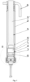
- Fig.1 a pyrotechnic actuator according to the invention in longitudinal section
- Fig. 2 Area II of Fig.1 on an enlarged scale
- Fig.3 a perspective view of the actuator of the Fig.1 and 2 .
- the actuator according to the invention (see Fig.1 ) has an actuator housing 2, to the upper end of which a mounting plate 8 is attached.
- a piston 5 with piston rod 5" and piston tulip 5' is movably arranged in this actuator housing 2.
- the piston rod 5" protrudes slightly from the actuator housing 2 in the initial position.
- Below the piston 5 is the pyrotechnic gas generator 4 with igniter 6, propellant charge 7 and propellant charge housing 1.
- the propellant housing 1 has a special shape (see Fig. 2 ): The outer diameter decreases at the point 3', whereas the inner diameter increases at another point further up (“top” as in Fig.1 and 2 seen) is reduced. This creates a predetermined breaking point 3 where the propellant charge housing 1 has a reduced wall thickness. This creates an area 1" (facing away from the igniter 6) which is a short distance from the inner wall of the actuator housing 2, and an area 1' (facing the igniter 6) where this is not the case; on the contrary, in this area 1' there is a press fit so that the gas generator 4 is fixed reliably and without play in the actuator housing 2.
- the propellant charge housing 1 is made of aluminum.
- the gap between the area 1" and the inner wall of the actuator housing 2 is 0.5 mm, and the height of the area 1", i.e. the distance of the predetermined breaking point 3 from the end of the propellant charge housing remote from the igniter, is 8 mm.
- the igniter 6 is now ignited, the propellant charge 7 is also ignited, and from a bursting pressure of 150 - 200 bar, the predetermined breaking point 3 breaks and the area 1" separates from the area 1'.
- the area 1" expands so that it lies tightly against the inner wall of the actuator housing 2. It is important that the gap that existed between the area 1" and the inner wall of the actuator housing 2 before the ignition is dimensioned in such a way that the area 1" is expanded so much that it lies tightly against the actuator housing 2, but that a large part of the pressure is necessary for the expansion of the area 1", so that the force with which the area 1" presses against the The pressure on the inner wall of the actuator housing 2 remains relatively low and thus the friction also remains relatively low.
- the torn-off area 1" thus pushes the piston 5 upwards out of the actuator housing 2, so that the piston rod 5" extends upwards out of the actuator housing 2.
Landscapes
- Engineering & Computer Science (AREA)
- General Engineering & Computer Science (AREA)
- Mechanical Engineering (AREA)
- Chemical & Material Sciences (AREA)
- Analytical Chemistry (AREA)
- Physics & Mathematics (AREA)
- Fluid Mechanics (AREA)
- Actuator (AREA)
Description
- Die vorliegende Erfindung betrifft einen pyrotechnischen Aktuator mit einem Aktuatorgehäuse, das über den Großteil seiner Länge einen zylindrischen Hohlraum umschließt, und mit einem Gasgenerator mit Zünder, Treibladung und Treibladungsgehäuse, wobei das Treibladungsgehäuse eine Sollbruchstelle in Form einer Verringerung der Dicke aufweist, und wobei der Durchmesser in dem Bereich, der auf der dem Zünder abgewandten Seite der Sollbruchstelle liegt, geringer ist als der Durchmesser in dem Bereich, der auf der dem Zünder zugewandten Seite der Sollbruchstelle liegt.
- Systeme zur Minderung der Verletzungsschwere von Fußgängern bei Unfällen mit Kraftfahrzeugen finden immer stärkere Verbreitung. Neben dem Notbremsassistenten, der im idealen Fall den Zusammenstoß des Fahrzeuges mit dem Fußgänger gänzlich verhindert, zumindest aber die Anprallgeschwindigkeit verringert, kommen auch Systeme zur Abmilderung der Unfallfolgen in nicht abwendbaren Situationen zum Einsatz. Diese stellen einen zusätzlichen Deformationsraum zwischen der Motorhaube und den harten Komponenten im Motorraum bereit, indem die Motorhaube im Scharnierbereich, bei manchen Premium-Fahrzeugen zusätzlich auch im Schlossbereich, angestellt wird. Zumeist wird diese Anstellung mit pyrotechnischen Aktuatoren bewerkstelligt, die bei geringem Bauraum die entsprechenden Kräfte gut aufbringen können.
- Ein derartiger Aktuator ist beispielsweise in
DE 102017112054 A von Hirtenberger (heute: Astotec) beschrieben. Es existiert eine große Anzahl an Herstellern und Varianten, beispielsweise wird auf dieEP 2699455 B von Autoliv oder dieUS 10875491 B von Key Safety Systems (heute: Joyson Safety Systems - Probleme bereiten jedoch große Leistungen. Hier wird in der Regel der Spalt zwischen Kolbentulpe und Innenwand des Gehäuses mittels eines O-Rings abgedichtet, manchmal ist auch ein zusätzlicher Bauteil, wie z.B. in
AT 12351U von Hirtenberger -
EP 2583870 A1 zeigt eine Kolben-Zylinder-Einheit, die eine Kappe aufweist, die so am Zylinder befestigt ist, dass sie durch Verschieben des Kolbens vom Zylinder gelöst bzw. abgerissen wird. -
EP 3260706 A1 zeigt einen pyrotechnischen Aktuator mit einem Abdeckelement um eine Zündeinheit, wobei das Abdeckelement im Falle einer Zündung einen Kolben antreiben soll. -
JP 2010084788 A - Ein pyrotechnischer Aktuator der eingangs genannten Art ist aus
DE 20312222U , Fig. 2a und 2b bekannt. Diese Vorrichtung dient jedoch nicht zum Anstellen einer Motorhaube, sondern als Sicherheitsgurtstraffer. Dementsprechend ist hier auch kein Kolben vorgesehen, sondern das Treibladungsgehäuse ist an dem dem Zünder abgewandten Ende massiv ausgeführt, bildet also selbst eine Art kurzen Kolben. - Gemäß dieser Schrift umschließt das Aktuatorgehäuse einen zylindrischen Hohlraum, wobei an diesen zylindrischen Hohlraum anschließend, im Bereich des Zünders, eine Stufe vorgesehen ist, hinter welcher der Durchmesser des Hohlraums vergrößert ist. Das Treibladungsgehäuse weist eine entsprechende Abstufung auf, und im Bereich dieser Abstufung ist die Dicke des Treibladungsgehäuses deutlich verringert, wodurch sich eine Sollbruchstelle ergibt. Bei Zündung reißt das Treibladungsgehäuse an dieser Stelle ab, und der abgerissene Teil mit dem massiv ausgeführten Ende bewegt sich im zylindrischen Hohlraum vom Zünder weg. Soweit dies aus den Zeichnungen erkennbar ist, liegt das Treibladungsgehäuse auf der dem Zünder abgewandten Seite der Abstufung vollflächig am Aktuatorgehäuse an.
- Es ist Aufgabe der vorliegenden Erfindung, einen pyrotechnischen Aktuator zu schaffen, der zum Anstellen von Motorhauben geeignet ist, der keinen O-Ring und auch kein zusätzliches Bauteil zur Abdichtung benötigt und der dennoch eine Abdichtung der vom pyrotechnischen Gasgenerator erzeugten Gase bewirkt, sodass diese ihre volle Wirkung entfalten können.
- Diese Aufgabe wird durch einen pyrotechnischen Aktuator der eingangs genannten Art erfindungsgemäß dadurch gelöst, dass im Aktuatorgehäuse ein im zylindrischen Hohlraum verschiebbarer Kolben vorgesehen ist, dass die Sollbruchstelle des Treibladungsgehäuses im zylindrischen Hohlraum des Aktuatorgehäuses liegt, dass auf der dem Zünder abgewandten Seite der Sollbruchstelle das Treibladungsgehäuse zur Innenwand des Aktuatorgehäuses einen Abstand hat, und dass bei der Zündung der Bereich des Treibladungsgehäuses, der auf der dem Zünder abgewandten Seite der Sollbruchstelle liegt, abgerissen wird und der abgerissene Bereich des Treibladungsgehäuses den Kolben antreibt und zur Innenwand des Aktuatorgehäuses abdichtet.
- Ein Aktuator bekannter Bauart besitzt erfindungsgemäß ein Treibladungsgehäuse mit einer Dünnstelle an der Seite und einem benachbarten Durchmessersprung. Abweichend zu den bekannten Designs weist das Treibladungsgehäuse keine Schwächung im Bodenbereich auf, beispielsweise durch die Prägung eines Sternes oder einer dünnwandigen Membrane in den Boden. Bei diesen bekannten Designs entweichen die Gase durch diese Schwächung aus dem Treibladungsgehäuse und treiben den Kolben direkt an.
- Erfindungsgemäß reißt hingegen bei Zündung des Zünders und somit der Treibladung das Treibladungsgehäuse an der Sollbruchstelle ab. Es bildet sich dadurch ein abgerissener Teil, der den Kolben antreibt und der für eine Dichtung gegenüber dem Aktuatorgehäuse sorgt, weil er durch den Druck der erzeugten Gase an die Innenwand des Aktuatorgehäuses gedrückt wird. Damit dieses Abreißen zuverlässig erfolgt, ist bevorzugt, dass die Verringerung der Dicke radial ist und umlaufend um das Treibladungsgehäuse ausgebildet ist.
- Von großer Bedeutung ist das Verhältnis zwischen der Position der Sollbruchstelle in Bezug zum oberen Rand des Treibladungsgehäuses und dem Durchmessersprung im Außendurchmesser des Treibladungsgehäuses. Liegt die Sollbruchstelle des Treibladungsgehäuses nahe der oberen Kante des Treibladungsgehäuses, ist nur ein kleiner Durchmessersprung überbrückbar. Ist die Sollbruchstelle weiter vom Ende des Treibladungsgehäuses entfernt, kann bedingt durch das "Aufblasen" des abgerissenen Teils des Treibladungsgehäuses ein größerer Spalt überbrückt werden.
- Andererseits führt eine längere Kontaktzone zwischen abgerissenem Teil des Treibladungsgehäuses und der Innenwand des Aktuatorgehäuses zu einer erhöhten Reibung und im Extremfall zum Festsetzen ohne Trennung. Außerdem verhindert ein zu großer Spalt den zuverlässigen Kontakt des abgerissenen Teils des Treibladungsgehäuses mit der Innenwand des Gehäuses, es existiert also ein optimaler Bereich.
- Für typische Aktuatoranwendungen mit einem Gehäuseinnendurchmesser von 13-20 mm und einem Treibladungsgehäuse aus AI 99,9 sind folgende Werte vorteilhaft:
- Ein Spaltdurchmesser im zünderfernen Bereich des Treibladungsgehäuses von 0,1 - 2 mm; ein Abstand der Sollbruchstelle zur Oberseite des Treibladungsgehäuses von 1 - 10 mm; und ein Berstdruck des Treibladungsgehäuses entlang der umlaufenden Sollbruchstelle von 50 - 500 bar.
- Es versteht sich von selbst, dass dieses Prinzip auch für Treibladungsgehäuse aus Stahl oder Kunststoff anwendbar ist.
- Es ist zweckmäßig, wenn die Sollbruchstelle dadurch realisiert ist, dass sich der Innendurchmesser des Treibladungsgehäuses an einer anderen Stelle als der Außendurchmesser verringert, sodass die Wandstärke zwischen diesen beiden Stellen reduziert ist. Dadurch wird eine besonders einfache Herstellung ermöglicht. Es ist aber auch möglich, dass die Sollbruchstelle durch eine Prägung im Treibladungsgehäuse realisiert ist, und auch, dass die Sollbruchstelle durch einen Einstich im Treibladungsgehäuse realisiert ist.
- In einer besonderen Ausgestaltung ist vorgesehen, dass das zündernahe Ende des Kolbens einen planen Boden besitzt. Dadurch kann sich der abgerissene Bereich des Treibladungsgehäuses gut an den Kolben anlegen.
- An Hand der beiliegenden Zeichnungen wird die vorliegende Erfindung näher erläutert. Es zeigt:
Fig. 1 einen erfindungsgemäßen pyrotechnischen Aktuator im Längsschnitt;Fig. 2 den Bereich II vonFig. 1 in vergrößertem Maßstab; undFig. 3 eine perspektivische Ansicht des Aktuators derFig. 1 und2 . - Der erfindungsgemäße Aktuator (siehe
Fig. 1 ) weist ein Aktuatorgehäuse 2 auf, an dessen oberem Ende eine Montageplatte 8 befestigt ist. In diesem Aktuatorgehäuse 2 ist ein Kolben 5 mit Kolbenstange 5" und Kolbentulpe 5' verschiebbar angeordnet. Die Kolbenstange 5" ragt in der Ausgangslage oben geringfügig aus dem Aktuatorgehäuse 2 hervor. Unterhalb des Kolbens 5 befindet sich der pyrotechnische Gasgenerator 4 mit Zünder 6, Treibladung 7 und Treibladungsgehäuse 1. - Erfindungsgemäß hat das Treibladungsgehäuse 1 eine spezielle Form (siehe
Fig. 2 ): Der Außendurchmesser verringert sich an der Stelle 3', wogegen sich der Innendurchmesser an einer anderen, weiter oben ("oben" wie inFig. 1 und2 gesehen) liegenden Stelle 3" verringert. Dadurch entsteht eine Sollbruchstelle 3, wo das Treibladungsgehäuse 1 eine verringerte Wandstärke hat. Es entsteht ein (vom Zünder 6 abgewandter) Bereich 1", der von der Innenwand des Aktuatorgehäuses 2 einen geringen Abstand hat, und ein (dem Zünder 6 zugewandter) Bereich 1', wo dies nicht der Fall ist, im Gegenteil, in diesem Bereich 1' liegt eine Presspassung vor, sodass der Gasgenerator 4 zuverlässig und spielfrei im Aktuatorgehäuse 2 fixiert ist. - Bei diesem Ausführungsbeispiel besteht das Treibladungsgehäuse 1 aus Aluminium. Der Spalt zwischen dem Bereich 1" und der Innenwand des Aktuatorgehäuses 2 beträgt 0,5 mm, und die Höhe des Bereichs 1", also der Abstand der Sollbruchstelle 3 vom zünderfernen Ende des Treibladungsgehäuses, beträgt 8 mm.
- Wird nun der Zünder 6 gezündet, wird auch die Treibladung 7 gezündet, und ab einem Berstdruck von 150 - 200 bar bricht die Sollbruchstelle 3, und der Bereich 1" löst sich vom Bereich 1'. Infolge des entstandenen Drucks weitet sich der Bereich 1" auf, sodass er an der Innenwand des Aktuatorgehäuses 2 dicht anliegt. Wesentlich ist, dass der Spalt, der vor der Zündung zwischen dem Bereich 1" und der Innenwand des Aktuatorgehäuses 2 vorhanden war, so dimensioniert ist, dass zwar der Bereich 1" so stark aufgeweitet wird, dass er dicht am Aktuatorgehäuse 2 anliegt, dass aber ein Großteil des Drucks für die Aufweitung des Bereichs 1" notwendig ist, sodass die Kraft, mit der der Bereich 1" gegen die Innenwand des Aktuatorgehäuses 2 gedrückt wird, relativ gering bleibt und somit auch die Reibung relativ gering bleibt. Der abgerissene Bereich 1" schiebt somit den Kolben 5 aus dem Aktuatorgehäuse 2 nach oben, sodass die Kolbenstange 5" aus dem Aktuatorgehäuse 2 nach oben ausfährt.
-
- 1 Treibladungsgehäuse
- 1', 1" Bereiche von 1
- 2 Aktuatorgehäuse
- 3 Sollbruchstelle
- 3' Stelle der Verringerung des Außendurchmessers
- 3" Stelle der Verringerung des Innendurchmessers
- 4 Gasgenerator
- 5 Kolben
- 5' Kolbentulpe
- 5" Kolbenstange
- 6 Zünder
- 7 Treibladung
- 8 Montageplatte
Claims (12)
- Pyrotechnischer Aktuator mit einem Aktuatorgehäuse (2), das über den Großteil seiner Länge einen zylindrischen Hohlraum umschließt, und mit einem Gasgenerator (4) mit Zünder, Treibladung und Treibladungsgehäuse (1), wobei das Treibladungsgehäuse (1) eine Sollbruchstelle (3) in Form einer Verringerung der Dicke aufweist, und wobei der Durchmesser in dem Bereich (1"), der auf der dem Zünder (6) abgewandten Seite der Sollbruchstelle (3) liegt, geringer ist als der Durchmesser in dem Bereich (1'), der auf der dem Zünder (6) zugewandten Seite der Sollbruchstelle (3) liegt, dadurch gekennzeichnet, dass im Aktuatorgehäuse (2) ein im zylindrischen Hohlraum verschiebbarer Kolben (5) vorgesehen ist, dass die Sollbruchstelle (3) des Treibladungsgehäuses (1) im zylindrischen Hohlraum des Aktuatorgehäuses (2) liegt, dass auf der dem Zünder (6) abgewandten Seite der Sollbruchstelle (3) das Treibladungsgehäuse (1) zur Innenwand des Aktuatorgehäuses (2) einen Abstand hat, und dass bei der Zündung der Bereich (1") des Treibladungsgehäuses (1), der auf der dem Zünder (6) abgewandten Seite der Sollbruchstelle (3) liegt, abgerissen wird und der abgerissene Bereich (1") des Treibladungsgehäuses (1) den Kolben (5) antreibt und zur Innenwand des Aktuatorgehäuses (2) abdichtet.
- Pyrotechnischer Aktuator nach Anspruch 1, dadurch gekennzeichnet, dass die Verringerung der Dicke radial ist und umlaufend um das Treibladungsgehäuse (1) ausgebildet ist.
- Pyrotechnischer Aktuator nach Anspruch 1 oder 2, dadurch gekennzeichnet, dass das Treibladungsgehäuse (1) bei Zündung an der Sollbruchstelle (3) abreißt und der Kolben (5) durch den abgerissenen Bereich (1") des Treibladungsgehäuses (1) angetrieben wird.
- Pyrotechnischer Aktuator nach einem der Ansprüche 1 bis 3, dadurch gekennzeichnet, dass der Spalt zwischen Innenwand des Aktuatorgehäuses (2) und dem zünderfernen Bereich (1") des Treibladungsgehäuses (1) 0,1 - 2 mm beträgt.
- Pyrotechnischer Aktuator nach einem der Ansprüche 1 bis 4, dadurch gekennzeichnet, dass der Abstand zwischen dem zünderfernen Ende des Treibladungsgehäuses (1) und der Sollbruchstelle (3), also die Höhe des zünderfernen Bereichs (1"), 1 - 10 mm beträgt.
- Pyrotechnischer Aktuator nach einem der Ansprüche 1 bis 5, dadurch gekennzeichnet, dass der Berstdruck, bei dem das Treibladungsgehäuse (1) entlang der Sollbruchstelle (3) aufreißt, 50 - 500 bar beträgt.
- Pyrotechnischer Aktuator nach einem der Ansprüche 1 bis 6, dadurch gekennzeichnet, dass das Treibladungsgehäuse (1) aus Aluminium oder einer Aluminium-Legierung besteht.
- Pyrotechnischer Aktuator nach einem der Ansprüche 1 bis 6, dadurch gekennzeichnet, dass das Treibladungsgehäuse (1) aus Stahl oder Kunststoff besteht.
- Pyrotechnischer Aktuator nach einem der Ansprüche 1 bis 8, dadurch gekennzeichnet, dass die Sollbruchstelle (3) dadurch realisiert ist, dass sich der Innendurchmesser des Treibladungsgehäuses (1) an einer anderen Stelle (3") als der Außendurchmesser verringert, sodass die Wandstärke zwischen diesen beiden Stellen (3', 3") reduziert ist.
- Pyrotechnischer Aktuator nach einem der Ansprüche 1 bis 8, dadurch gekennzeichnet, dass die Sollbruchstelle (3) durch eine Prägung im Treibladungsgehäuse (1) realisiert ist.
- Pyrotechnischer Aktuator nach einem der Ansprüche 1 bis 8, dadurch gekennzeichnet, dass die Sollbruchstelle (3) durch einen Einstich im Treibladungsgehäuse (1) realisiert ist.
- Pyrotechnischer Aktuator nach einem der Ansprüche 1 bis 11, dadurch gekennzeichnet, dass das zündernahe Ende des Kolbens (5) einen planen Boden besitzt.
Applications Claiming Priority (1)
| Application Number | Priority Date | Filing Date | Title |
|---|---|---|---|
| ATA50491/2022A AT526224B1 (de) | 2022-07-05 | 2022-07-05 | Pyrotechnischer Aktuator |
Publications (2)
| Publication Number | Publication Date |
|---|---|
| EP4303450A1 EP4303450A1 (de) | 2024-01-10 |
| EP4303450B1 true EP4303450B1 (de) | 2024-09-18 |
Family
ID=87137031
Family Applications (1)
| Application Number | Title | Priority Date | Filing Date |
|---|---|---|---|
| EP23183515.8A Active EP4303450B1 (de) | 2022-07-05 | 2023-07-05 | Pyrotechnischer aktuator |
Country Status (2)
| Country | Link |
|---|---|
| EP (1) | EP4303450B1 (de) |
| AT (1) | AT526224B1 (de) |
Family Cites Families (14)
| Publication number | Priority date | Publication date | Assignee | Title |
|---|---|---|---|---|
| DE69406829T2 (de) * | 1993-03-23 | 1998-06-18 | Trw Inc | Aufblaseinrichtung |
| FR2788846B1 (fr) * | 1999-01-25 | 2001-10-26 | Livbag Snc | Generateur de gaz hybride muni d'un initiateur a chargement explosif profile |
| US6543806B1 (en) * | 2000-08-03 | 2003-04-08 | Nxgen Technologies Llc | Inflator for vehicle protection apparatus |
| DE20312222U1 (de) * | 2003-08-07 | 2003-12-18 | Trw Occupant Restraint Systems Gmbh & Co. Kg | Vorrichtung zum Straffen eines Sicherheitsgurts mit pyrotechnischem Linearantrieb |
| US6942261B2 (en) * | 2003-08-14 | 2005-09-13 | Autoliv Asp, Inc. | Linear actuator with an internal dampening mechanism |
| JP5296474B2 (ja) * | 2008-09-29 | 2013-09-25 | 日本プラスト株式会社 | パイロアクチュエータ |
| FR2937691B1 (fr) * | 2008-10-28 | 2011-06-10 | Snpe Materiaux Energetiques | Verin a course declenchee pour systeme de securite |
| AT12351U1 (de) | 2010-12-22 | 2012-04-15 | Hirtenberger Automotive Safety Gmbh & Co Kg | Betätigungseinrichtung |
| EP2699455B1 (de) | 2011-04-18 | 2016-03-30 | Autoliv Development AB | Hebeanordnung für eine motorhaube |
| CZ303856B6 (cs) * | 2011-09-24 | 2013-05-29 | Indet Safety Systems A. S. | Posuvný semireverzibilní pyrotechnický aktivátor bezpecnostních systému automobilu, zejména pro ochranu chodcu |
| DE102011116590B4 (de) * | 2011-10-21 | 2025-05-28 | Zf Airbag Germany Gmbh | Kolben-Zylinder-Einheit, Verfahren zum Betrieb und Verfahren zur Herstellung einer solchen Kolben-Zylinder-Einheit sowie fahrzeugintegriertes Personensicherheitssystem |
| JP6407759B2 (ja) * | 2015-02-17 | 2018-10-17 | 株式会社ダイセル | パイロ式アクチュエータ機構、注射器、及び点火器組立体 |
| AT518680B1 (de) | 2016-06-02 | 2018-10-15 | Hirtenberger Automotive Safety Gmbh & Co Kg | Pyrotechnischer Aktuator |
| US10875491B2 (en) | 2018-12-28 | 2020-12-29 | Key Safety Systems, Inc. | Body panel lifter mechanical energy management system |
-
2022
- 2022-07-05 AT ATA50491/2022A patent/AT526224B1/de active
-
2023
- 2023-07-05 EP EP23183515.8A patent/EP4303450B1/de active Active
Also Published As
| Publication number | Publication date |
|---|---|
| AT526224A1 (de) | 2024-01-15 |
| EP4303450A1 (de) | 2024-01-10 |
| AT526224B1 (de) | 2024-02-15 |
Similar Documents
| Publication | Publication Date | Title |
|---|---|---|
| DE19626404C2 (de) | Verschluß für einen Druckbehälter | |
| DE102006011927A1 (de) | Pyrotechnischer Aktuator | |
| DE112014004496B4 (de) | Aktor | |
| EP1443296B1 (de) | Pyromechanisches Trennelement | |
| AT522245B1 (de) | Aktuator, insbesondere zum Anstellen von Motorhauben | |
| WO2023102589A1 (de) | Pyrotechnischer aktuator | |
| EP0656522A1 (de) | Patronenhülse | |
| DE10331921B3 (de) | Verstellelement mit einem Zylinder | |
| DE102015016193A1 (de) | Pyrotechnischer Aktuator für ein Fahrzeugsicherheitssystem, Aktuatorbaugruppe, Fahrzeugsicherheitssystem mit einem solchen Aktuator sowie Betätigungsverfahren | |
| EP1561649B1 (de) | Kaltgasgenerator | |
| DE102014018007B4 (de) | Hybridgasgenerator für ein Fahrzeugsicherheitssystem mit einer Öffnungsvorrichtung für einen Druckgasbehälter | |
| EP0944504B1 (de) | Hybrid-gasgenerator für einen airbag | |
| EP4303450B1 (de) | Pyrotechnischer aktuator | |
| EP3658421B1 (de) | Überzündschutzvorrichtung, zweite zündstufe, gasgenerator sowie gassackmodul | |
| DE102011106514B4 (de) | Pyrotechnischer Aktuator mit Entlüftung, Motorhaubenaufsteller und Gurtstraffer mit einem solchen Aktuator | |
| EP1745993B1 (de) | Vorrichtung zum Aufstellen der Fronthaube eines Kraftfahrzeuges | |
| DE112015000803T5 (de) | Gasgenerator | |
| EP0776796A2 (de) | Pyrotechnischer Gasgenerator | |
| AT524574A4 (de) | Aktuator zum Anheben einer Motorhaube | |
| AT12351U1 (de) | Betätigungseinrichtung | |
| EP4141264B1 (de) | Pyrotechnischer aktuator sowie verfahren zur herstellung seiner kolbenstange | |
| AT526223B1 (de) | Pyrotechnischer Aktuator | |
| AT526349B1 (de) | Pyrotechnischer Aktuator | |
| DE10346031B4 (de) | Energie aufnehmende Vorrichtung, insbesondere für Lenksäulen | |
| EP2065672B1 (de) | Miniaturisiertes Kraftelement |
Legal Events
| Date | Code | Title | Description |
|---|---|---|---|
| PUAI | Public reference made under article 153(3) epc to a published international application that has entered the european phase |
Free format text: ORIGINAL CODE: 0009012 |
|
| STAA | Information on the status of an ep patent application or granted ep patent |
Free format text: STATUS: THE APPLICATION HAS BEEN PUBLISHED |
|
| AK | Designated contracting states |
Kind code of ref document: A1 Designated state(s): AL AT BE BG CH CY CZ DE DK EE ES FI FR GB GR HR HU IE IS IT LI LT LU LV MC ME MK MT NL NO PL PT RO RS SE SI SK SM TR |
|
| STAA | Information on the status of an ep patent application or granted ep patent |
Free format text: STATUS: REQUEST FOR EXAMINATION WAS MADE |
|
| 17P | Request for examination filed |
Effective date: 20240223 |
|
| RBV | Designated contracting states (corrected) |
Designated state(s): AL AT BE BG CH CY CZ DE DK EE ES FI FR GB GR HR HU IE IS IT LI LT LU LV MC ME MK MT NL NO PL PT RO RS SE SI SK SM TR |
|
| GRAP | Despatch of communication of intention to grant a patent |
Free format text: ORIGINAL CODE: EPIDOSNIGR1 |
|
| STAA | Information on the status of an ep patent application or granted ep patent |
Free format text: STATUS: GRANT OF PATENT IS INTENDED |
|
| RIC1 | Information provided on ipc code assigned before grant |
Ipc: F15B 15/14 20060101ALN20240328BHEP Ipc: B60R 21/38 20110101ALN20240328BHEP Ipc: F15B 15/19 20060101AFI20240328BHEP |
|
| INTG | Intention to grant announced |
Effective date: 20240419 |
|
| RIC1 | Information provided on ipc code assigned before grant |
Ipc: F15B 15/14 20060101ALN20240409BHEP Ipc: B60R 21/38 20110101ALN20240409BHEP Ipc: F15B 15/19 20060101AFI20240409BHEP |
|
| GRAS | Grant fee paid |
Free format text: ORIGINAL CODE: EPIDOSNIGR3 |
|
| GRAA | (expected) grant |
Free format text: ORIGINAL CODE: 0009210 |
|
| STAA | Information on the status of an ep patent application or granted ep patent |
Free format text: STATUS: THE PATENT HAS BEEN GRANTED |
|
| AK | Designated contracting states |
Kind code of ref document: B1 Designated state(s): AL AT BE BG CH CY CZ DE DK EE ES FI FR GB GR HR HU IE IS IT LI LT LU LV MC ME MK MT NL NO PL PT RO RS SE SI SK SM TR |
|
| REG | Reference to a national code |
Ref country code: GB Ref legal event code: FG4D Free format text: NOT ENGLISH |
|
| REG | Reference to a national code |
Ref country code: CH Ref legal event code: EP |
|
| REG | Reference to a national code |
Ref country code: IE Ref legal event code: FG4D Free format text: LANGUAGE OF EP DOCUMENT: GERMAN |
|
| REG | Reference to a national code |
Ref country code: DE Ref legal event code: R096 Ref document number: 502023000179 Country of ref document: DE |
|
| REG | Reference to a national code |
Ref country code: LT Ref legal event code: MG9D |
|
| PG25 | Lapsed in a contracting state [announced via postgrant information from national office to epo] |
Ref country code: NO Free format text: LAPSE BECAUSE OF FAILURE TO SUBMIT A TRANSLATION OF THE DESCRIPTION OR TO PAY THE FEE WITHIN THE PRESCRIBED TIME-LIMIT Effective date: 20241218 |
|
| PG25 | Lapsed in a contracting state [announced via postgrant information from national office to epo] |
Ref country code: GR Free format text: LAPSE BECAUSE OF FAILURE TO SUBMIT A TRANSLATION OF THE DESCRIPTION OR TO PAY THE FEE WITHIN THE PRESCRIBED TIME-LIMIT Effective date: 20241219 Ref country code: FI Free format text: LAPSE BECAUSE OF FAILURE TO SUBMIT A TRANSLATION OF THE DESCRIPTION OR TO PAY THE FEE WITHIN THE PRESCRIBED TIME-LIMIT Effective date: 20240918 |
|
| PG25 | Lapsed in a contracting state [announced via postgrant information from national office to epo] |
Ref country code: BG Free format text: LAPSE BECAUSE OF FAILURE TO SUBMIT A TRANSLATION OF THE DESCRIPTION OR TO PAY THE FEE WITHIN THE PRESCRIBED TIME-LIMIT Effective date: 20240918 |
|
| PG25 | Lapsed in a contracting state [announced via postgrant information from national office to epo] |
Ref country code: LV Free format text: LAPSE BECAUSE OF FAILURE TO SUBMIT A TRANSLATION OF THE DESCRIPTION OR TO PAY THE FEE WITHIN THE PRESCRIBED TIME-LIMIT Effective date: 20240918 |
|
| PG25 | Lapsed in a contracting state [announced via postgrant information from national office to epo] |
Ref country code: HR Free format text: LAPSE BECAUSE OF FAILURE TO SUBMIT A TRANSLATION OF THE DESCRIPTION OR TO PAY THE FEE WITHIN THE PRESCRIBED TIME-LIMIT Effective date: 20240918 |
|
| REG | Reference to a national code |
Ref country code: NL Ref legal event code: MP Effective date: 20240918 |
|
| PG25 | Lapsed in a contracting state [announced via postgrant information from national office to epo] |
Ref country code: RS Free format text: LAPSE BECAUSE OF FAILURE TO SUBMIT A TRANSLATION OF THE DESCRIPTION OR TO PAY THE FEE WITHIN THE PRESCRIBED TIME-LIMIT Effective date: 20241218 |
|
| PG25 | Lapsed in a contracting state [announced via postgrant information from national office to epo] |
Ref country code: RS Free format text: LAPSE BECAUSE OF FAILURE TO SUBMIT A TRANSLATION OF THE DESCRIPTION OR TO PAY THE FEE WITHIN THE PRESCRIBED TIME-LIMIT Effective date: 20241218 Ref country code: NO Free format text: LAPSE BECAUSE OF FAILURE TO SUBMIT A TRANSLATION OF THE DESCRIPTION OR TO PAY THE FEE WITHIN THE PRESCRIBED TIME-LIMIT Effective date: 20241218 Ref country code: LV Free format text: LAPSE BECAUSE OF FAILURE TO SUBMIT A TRANSLATION OF THE DESCRIPTION OR TO PAY THE FEE WITHIN THE PRESCRIBED TIME-LIMIT Effective date: 20240918 Ref country code: HR Free format text: LAPSE BECAUSE OF FAILURE TO SUBMIT A TRANSLATION OF THE DESCRIPTION OR TO PAY THE FEE WITHIN THE PRESCRIBED TIME-LIMIT Effective date: 20240918 Ref country code: GR Free format text: LAPSE BECAUSE OF FAILURE TO SUBMIT A TRANSLATION OF THE DESCRIPTION OR TO PAY THE FEE WITHIN THE PRESCRIBED TIME-LIMIT Effective date: 20241219 Ref country code: FI Free format text: LAPSE BECAUSE OF FAILURE TO SUBMIT A TRANSLATION OF THE DESCRIPTION OR TO PAY THE FEE WITHIN THE PRESCRIBED TIME-LIMIT Effective date: 20240918 Ref country code: BG Free format text: LAPSE BECAUSE OF FAILURE TO SUBMIT A TRANSLATION OF THE DESCRIPTION OR TO PAY THE FEE WITHIN THE PRESCRIBED TIME-LIMIT Effective date: 20240918 |
|
| PG25 | Lapsed in a contracting state [announced via postgrant information from national office to epo] |
Ref country code: NL Free format text: LAPSE BECAUSE OF FAILURE TO SUBMIT A TRANSLATION OF THE DESCRIPTION OR TO PAY THE FEE WITHIN THE PRESCRIBED TIME-LIMIT Effective date: 20240918 |
|
| PG25 | Lapsed in a contracting state [announced via postgrant information from national office to epo] |
Ref country code: IS Free format text: LAPSE BECAUSE OF FAILURE TO SUBMIT A TRANSLATION OF THE DESCRIPTION OR TO PAY THE FEE WITHIN THE PRESCRIBED TIME-LIMIT Effective date: 20250118 Ref country code: PT Free format text: LAPSE BECAUSE OF FAILURE TO SUBMIT A TRANSLATION OF THE DESCRIPTION OR TO PAY THE FEE WITHIN THE PRESCRIBED TIME-LIMIT Effective date: 20250120 |
|
| PG25 | Lapsed in a contracting state [announced via postgrant information from national office to epo] |
Ref country code: RO Free format text: LAPSE BECAUSE OF FAILURE TO SUBMIT A TRANSLATION OF THE DESCRIPTION OR TO PAY THE FEE WITHIN THE PRESCRIBED TIME-LIMIT Effective date: 20240918 Ref country code: SM Free format text: LAPSE BECAUSE OF FAILURE TO SUBMIT A TRANSLATION OF THE DESCRIPTION OR TO PAY THE FEE WITHIN THE PRESCRIBED TIME-LIMIT Effective date: 20240918 |
|
| PG25 | Lapsed in a contracting state [announced via postgrant information from national office to epo] |
Ref country code: ES Free format text: LAPSE BECAUSE OF FAILURE TO SUBMIT A TRANSLATION OF THE DESCRIPTION OR TO PAY THE FEE WITHIN THE PRESCRIBED TIME-LIMIT Effective date: 20240918 |
|
| PG25 | Lapsed in a contracting state [announced via postgrant information from national office to epo] |
Ref country code: EE Free format text: LAPSE BECAUSE OF FAILURE TO SUBMIT A TRANSLATION OF THE DESCRIPTION OR TO PAY THE FEE WITHIN THE PRESCRIBED TIME-LIMIT Effective date: 20240918 |
|
| PG25 | Lapsed in a contracting state [announced via postgrant information from national office to epo] |
Ref country code: PL Free format text: LAPSE BECAUSE OF FAILURE TO SUBMIT A TRANSLATION OF THE DESCRIPTION OR TO PAY THE FEE WITHIN THE PRESCRIBED TIME-LIMIT Effective date: 20240918 Ref country code: CZ Free format text: LAPSE BECAUSE OF FAILURE TO SUBMIT A TRANSLATION OF THE DESCRIPTION OR TO PAY THE FEE WITHIN THE PRESCRIBED TIME-LIMIT Effective date: 20240918 |
|
| PG25 | Lapsed in a contracting state [announced via postgrant information from national office to epo] |
Ref country code: SK Free format text: LAPSE BECAUSE OF FAILURE TO SUBMIT A TRANSLATION OF THE DESCRIPTION OR TO PAY THE FEE WITHIN THE PRESCRIBED TIME-LIMIT Effective date: 20240918 Ref country code: IT Free format text: LAPSE BECAUSE OF FAILURE TO SUBMIT A TRANSLATION OF THE DESCRIPTION OR TO PAY THE FEE WITHIN THE PRESCRIBED TIME-LIMIT Effective date: 20240918 |
|
| REG | Reference to a national code |
Ref country code: DE Ref legal event code: R097 Ref document number: 502023000179 Country of ref document: DE |
|
| PG25 | Lapsed in a contracting state [announced via postgrant information from national office to epo] |
Ref country code: DK Free format text: LAPSE BECAUSE OF FAILURE TO SUBMIT A TRANSLATION OF THE DESCRIPTION OR TO PAY THE FEE WITHIN THE PRESCRIBED TIME-LIMIT Effective date: 20240918 |
|
| PLBE | No opposition filed within time limit |
Free format text: ORIGINAL CODE: 0009261 |
|
| STAA | Information on the status of an ep patent application or granted ep patent |
Free format text: STATUS: NO OPPOSITION FILED WITHIN TIME LIMIT |
|
| 26N | No opposition filed |
Effective date: 20250619 |
|
| PG25 | Lapsed in a contracting state [announced via postgrant information from national office to epo] |
Ref country code: SE Free format text: LAPSE BECAUSE OF FAILURE TO SUBMIT A TRANSLATION OF THE DESCRIPTION OR TO PAY THE FEE WITHIN THE PRESCRIBED TIME-LIMIT Effective date: 20240918 |
|
| PGFP | Annual fee paid to national office [announced via postgrant information from national office to epo] |
Ref country code: DE Payment date: 20250606 Year of fee payment: 3 |
|
| PGFP | Annual fee paid to national office [announced via postgrant information from national office to epo] |
Ref country code: AT Payment date: 20251020 Year of fee payment: 3 |