EP4302928A1 - Handgeführtes, akkubetriebenes arbeitsgerät - Google Patents
Handgeführtes, akkubetriebenes arbeitsgerät Download PDFInfo
- Publication number
- EP4302928A1 EP4302928A1 EP22211746.7A EP22211746A EP4302928A1 EP 4302928 A1 EP4302928 A1 EP 4302928A1 EP 22211746 A EP22211746 A EP 22211746A EP 4302928 A1 EP4302928 A1 EP 4302928A1
- Authority
- EP
- European Patent Office
- Prior art keywords
- housing
- plane
- working device
- area
- horizontal plane
- Prior art date
- Legal status (The legal status is an assumption and is not a legal conclusion. Google has not performed a legal analysis and makes no representation as to the accuracy of the status listed.)
- Granted
Links
Images



Classifications
-
- B—PERFORMING OPERATIONS; TRANSPORTING
- B25—HAND TOOLS; PORTABLE POWER-DRIVEN TOOLS; MANIPULATORS
- B25F—COMBINATION OR MULTI-PURPOSE TOOLS NOT OTHERWISE PROVIDED FOR; DETAILS OR COMPONENTS OF PORTABLE POWER-DRIVEN TOOLS NOT PARTICULARLY RELATED TO THE OPERATIONS PERFORMED AND NOT OTHERWISE PROVIDED FOR
- B25F5/00—Details or components of portable power-driven tools not particularly related to the operations performed and not otherwise provided for
-
- B—PERFORMING OPERATIONS; TRANSPORTING
- B25—HAND TOOLS; PORTABLE POWER-DRIVEN TOOLS; MANIPULATORS
- B25F—COMBINATION OR MULTI-PURPOSE TOOLS NOT OTHERWISE PROVIDED FOR; DETAILS OR COMPONENTS OF PORTABLE POWER-DRIVEN TOOLS NOT PARTICULARLY RELATED TO THE OPERATIONS PERFORMED AND NOT OTHERWISE PROVIDED FOR
- B25F5/00—Details or components of portable power-driven tools not particularly related to the operations performed and not otherwise provided for
- B25F5/02—Construction of casings, bodies or handles
-
- A—HUMAN NECESSITIES
- A01—AGRICULTURE; FORESTRY; ANIMAL HUSBANDRY; HUNTING; TRAPPING; FISHING
- A01G—HORTICULTURE; CULTIVATION OF VEGETABLES, FLOWERS, RICE, FRUIT, VINES, HOPS OR SEAWEED; FORESTRY; WATERING
- A01G3/00—Cutting implements specially adapted for horticultural purposes; Delimbing standing trees
- A01G3/04—Apparatus for trimming hedges, e.g. hedge shears
- A01G3/047—Apparatus for trimming hedges, e.g. hedge shears portable
- A01G3/053—Apparatus for trimming hedges, e.g. hedge shears portable motor-driven
-
- A—HUMAN NECESSITIES
- A01—AGRICULTURE; FORESTRY; ANIMAL HUSBANDRY; HUNTING; TRAPPING; FISHING
- A01G—HORTICULTURE; CULTIVATION OF VEGETABLES, FLOWERS, RICE, FRUIT, VINES, HOPS OR SEAWEED; FORESTRY; WATERING
- A01G3/00—Cutting implements specially adapted for horticultural purposes; Delimbing standing trees
- A01G3/08—Other tools for pruning, branching or delimbing standing trees
- A01G3/085—Motor-driven saws for pruning or branching
-
- B—PERFORMING OPERATIONS; TRANSPORTING
- B24—GRINDING; POLISHING
- B24B—MACHINES, DEVICES, OR PROCESSES FOR GRINDING OR POLISHING; DRESSING OR CONDITIONING OF ABRADING SURFACES; FEEDING OF GRINDING, POLISHING, OR LAPPING AGENTS
- B24B27/00—Other grinding machines or devices
- B24B27/06—Grinders for cutting-off
- B24B27/08—Grinders for cutting-off being portable
-
- B—PERFORMING OPERATIONS; TRANSPORTING
- B27—WORKING OR PRESERVING WOOD OR SIMILAR MATERIAL; NAILING OR STAPLING MACHINES IN GENERAL
- B27B—SAWS FOR WOOD OR SIMILAR MATERIAL; COMPONENTS OR ACCESSORIES THEREFOR
- B27B17/00—Chain saws; Equipment therefor
- B27B17/0008—Means for carrying the chain saw, e.g. handles
-
- H—ELECTRICITY
- H01—ELECTRIC ELEMENTS
- H01M—PROCESSES OR MEANS, e.g. BATTERIES, FOR THE DIRECT CONVERSION OF CHEMICAL ENERGY INTO ELECTRICAL ENERGY
- H01M50/00—Constructional details or processes of manufacture of the non-active parts of electrochemical cells other than fuel cells, e.g. hybrid cells
- H01M50/20—Mountings; Secondary casings or frames; Racks, modules or packs; Suspension devices; Shock absorbers; Transport or carrying devices; Holders
- H01M50/233—Mountings; Secondary casings or frames; Racks, modules or packs; Suspension devices; Shock absorbers; Transport or carrying devices; Holders characterised by physical properties of casings or racks, e.g. dimensions
- H01M50/242—Mountings; Secondary casings or frames; Racks, modules or packs; Suspension devices; Shock absorbers; Transport or carrying devices; Holders characterised by physical properties of casings or racks, e.g. dimensions adapted for protecting batteries against vibrations, collision impact or swelling
-
- H—ELECTRICITY
- H01—ELECTRIC ELEMENTS
- H01M—PROCESSES OR MEANS, e.g. BATTERIES, FOR THE DIRECT CONVERSION OF CHEMICAL ENERGY INTO ELECTRICAL ENERGY
- H01M50/00—Constructional details or processes of manufacture of the non-active parts of electrochemical cells other than fuel cells, e.g. hybrid cells
- H01M50/20—Mountings; Secondary casings or frames; Racks, modules or packs; Suspension devices; Shock absorbers; Transport or carrying devices; Holders
- H01M50/244—Secondary casings; Racks; Suspension devices; Carrying devices; Holders characterised by their mounting method
-
- H—ELECTRICITY
- H01—ELECTRIC ELEMENTS
- H01M—PROCESSES OR MEANS, e.g. BATTERIES, FOR THE DIRECT CONVERSION OF CHEMICAL ENERGY INTO ELECTRICAL ENERGY
- H01M50/00—Constructional details or processes of manufacture of the non-active parts of electrochemical cells other than fuel cells, e.g. hybrid cells
- H01M50/20—Mountings; Secondary casings or frames; Racks, modules or packs; Suspension devices; Shock absorbers; Transport or carrying devices; Holders
- H01M50/247—Mountings; Secondary casings or frames; Racks, modules or packs; Suspension devices; Shock absorbers; Transport or carrying devices; Holders specially adapted for portable devices, e.g. mobile phones, computers, hand tools or pacemakers
-
- H—ELECTRICITY
- H01—ELECTRIC ELEMENTS
- H01M—PROCESSES OR MEANS, e.g. BATTERIES, FOR THE DIRECT CONVERSION OF CHEMICAL ENERGY INTO ELECTRICAL ENERGY
- H01M50/00—Constructional details or processes of manufacture of the non-active parts of electrochemical cells other than fuel cells, e.g. hybrid cells
- H01M50/20—Mountings; Secondary casings or frames; Racks, modules or packs; Suspension devices; Shock absorbers; Transport or carrying devices; Holders
- H01M50/289—Mountings; Secondary casings or frames; Racks, modules or packs; Suspension devices; Shock absorbers; Transport or carrying devices; Holders characterised by spacing elements or positioning means within frames, racks or packs
-
- Y—GENERAL TAGGING OF NEW TECHNOLOGICAL DEVELOPMENTS; GENERAL TAGGING OF CROSS-SECTIONAL TECHNOLOGIES SPANNING OVER SEVERAL SECTIONS OF THE IPC; TECHNICAL SUBJECTS COVERED BY FORMER USPC CROSS-REFERENCE ART COLLECTIONS [XRACs] AND DIGESTS
- Y02—TECHNOLOGIES OR APPLICATIONS FOR MITIGATION OR ADAPTATION AGAINST CLIMATE CHANGE
- Y02E—REDUCTION OF GREENHOUSE GAS [GHG] EMISSIONS, RELATED TO ENERGY GENERATION, TRANSMISSION OR DISTRIBUTION
- Y02E60/00—Enabling technologies; Technologies with a potential or indirect contribution to GHG emissions mitigation
- Y02E60/10—Energy storage using batteries
Definitions
- the invention relates to a hand-held, battery-operated work tool according to the preamble of claim 1.
- the invention further relates to a hand-held, battery-operated work tool according to the preamble of claim 11.
- Such work tools usually have a battery slot to accommodate a battery pack.
- the battery compartment should be designed to be very robust.
- the corresponding housing must have strong ribbing and takes up a corresponding amount of space.
- the invention is based on the object of developing a generic working device in such a way that a compact and at the same time robust design of the working device against an impact of the working device is possible.
- the invention provides according to claim 1 that an imaginary tangential plane of the housing touches the handle tube and touches the housing in the operating area.
- the imaginary tangential plane touches the operating area of the housing Side view perpendicular to the longitudinal plane at a point of contact.
- the tangential plane only touches the housing.
- the tangential plane of the housing does not intersect the housing.
- the operating area extends, in particular when viewed perpendicular to the longitudinal plane, in the direction of the longitudinal axis of the housing.
- the tool is arranged at the front end of the housing with respect to the longitudinal axis.
- the operating area is assigned to the rear end of the housing with respect to the longitudinal axis.
- the control element for operating the electric motor is arranged in the operating area.
- the handle opening is located in the operating area.
- the operating area extends in the direction of the longitudinal axis of the housing from the rear end of the housing to the distance point.
- the distance point is the point or location of the handle opening that has the greatest distance, measured in the direction of the longitudinal axis, from the rear end of the housing.
- the housing has a front area which extends in the direction of the longitudinal axis from the distance point to the front end of the housing.
- the housing is divided in the direction of the longitudinal axis exclusively into two main areas, namely the operating area and the front area.
- the handle opening completely penetrates the housing in the direction transverse to the longitudinal plane, in particular in the direction perpendicular to the longitudinal plane.
- the longitudinal plane contains the longitudinal axis.
- the longitudinal plane runs perpendicular to the horizontal plane when the implement is parked.
- the implement is designed so that it can be parked in the intended parking position on the horizontal plane.
- the implement has a storage area.
- the horizontal plane runs horizontally.
- the handle tube surrounds the housing at least partially.
- the handle tube extends over the housing.
- the imaginary tangential plane does not intersect the handle tube.
- the imaginary tangential plane touches the housing in the parking position on the side of the implement facing away from the horizontal plane.
- the imaginary tangential plane rests on the handle tube of the working device and touches the housing in the operating area, the area of the housing that is arranged in the direction of the longitudinal axis between the distance point and the front end of the housing is protected in the event of an impact of the working device.
- the intermediate area no parts of the housing protrude beyond the imaginary tangential plane.
- the intermediate area is protected, particularly in the event of an impact of the motor chainsaw with the imaginary tangential plane on the horizontal plane.
- the normal of the tangential plane is perpendicular to the horizontal plane. Accordingly, the implement falls onto the horizontal plane in such a way that the imaginary tangential plane contacts the horizontal plane flatly during initial contact.
- the imaginary tangential plane touches the operating area at a contact point.
- the touch point is the point of the operating area with the greatest distance from the horizontal plane.
- the tangent plane has a first side and a second side.
- the first side faces the horizontal plane when the implement is parked.
- the front area of the housing is preferably arranged exclusively on the first side of the imaginary tangential plane. As a result, the front area, in particular a battery slot arranged in the front area, is protected in the event of an impact.
- the front area has a front area distance from the imaginary tangential plane.
- the front area distance is advantageously chosen to be so small and the working device is designed in such a way that the front area of the housing can contact the horizontal plane in the event of an impact of the working device with the imaginary tangential plane on the horizontal plane.
- the front area in particular a battery slot arranged in the front area, can serve as a support point in the event of an impact with the implement, via which energy is absorbed into the housing. This means that the energy that must be absorbed into the housing in the event of an impact with the implement is distributed over several points.
- the imaginary tangential plane touches the operating area of the housing in the parking position in a side view perpendicular to the longitudinal plane in the contact point.
- the front area distance is advantageously less than 10% of the distance of the contact point to the horizontal plane.
- the front area distance is less than 5%, preferably less than 3%, of the distance of the contact point to the horizontal plane.
- the imaginary tangential plane touches the front area.
- the front area distance is 0% of the distance of the touch point to the horizontal plane. Because the front area distance is selected to be small, the front area can serve as a supporting element of the housing in the event of an impact, in particular in the event of an impact of the tangential plane on the horizontal plane.
- a battery slot is arranged in the front area of the housing so that the housing can enclose a battery.
- the battery slot does not protrude beyond the imaginary tangential plane.
- the working device and the battery compartment are advantageously designed in such a way that a battery pack arranged in the battery compartment is arranged exclusively on the first side of the imaginary tangential plane. This also protects the battery pack in the event of an impact.
- the front area of the housing has an impact projection.
- the impact projection is in particular part of the housing.
- the impact projection protrudes toward the tangential plane.
- the front area preferably has the smallest distance to the tangential plane in the area of the impact projection.
- the impact projection is part of the battery compartment.
- the impact projection preferably forms an outer wall of the battery compartment.
- the impact projection serves as an energy introduction point for energy into the housing of the working device in addition to the contact point of the tangential plane in the operating area of the housing and the handle tube.
- the working device advantageously includes an actuating element for ejecting a battery from the battery compartment.
- the working device is preferably designed in such a way that the actuating element is protected by the impact projection in the event of an impact with the working device.
- the actuating element can be at a greater distance from the imaginary tangential plane than the impact projection. This ensures that the functionality of the actuating element continues to exist even after an impact with the implement.
- the operating area has a hand stop for placing the hand when the operating element is actuated.
- the imaginary tangential plane advantageously touches the operating area on the hand stop.
- the hand stop can also be used as an energy introduction point or energy introduction point in the event of an impact with the implement.
- the hand stop is preferably designed as a projection of the operating area.
- the hand stop is essentially hump-shaped. This allows the implement to roll over the projection of the operating area in the event of an impact and then also absorb energy via the handle tube.
- a battery can be inserted into the battery slot in an insertion direction.
- the insertion direction preferably runs parallel to the longitudinal plane.
- the insertion direction in the storage position is advantageously inclined at an angle of 80° to 90° relative to the horizontal plane. It can also be provided that the insertion direction is perpendicular to the horizontal plane.
- the battery compartment has an insertion opening.
- the insertion opening is preferably arranged in the storage position on the side of the working device facing away from the horizontal plane.
- the insertion opening opens the battery compartment in the storage position in the direction away from the horizontal plane.
- This arrangement of the battery pack enables an ergonomic and balanced design of the working device.
- the battery pack can, for example, be arranged in the center of gravity of the implement.
- the introduction and execution of the Battery packs can be conveniently placed in and out of the battery compartment from above in the storage position.
- the battery compartment is designed such that the housing encloses a battery accommodated in the battery compartment.
- the working device has a further control element in the operating area.
- the further control element is preferably used to unlock the control element or to hold a locking element in an unlocking position.
- the further control element is a locking element for locking the control element or a holding element.
- the locking element is in particular provided in such a way that the operating element can only be actuated if the locking element is also actuated at the same time.
- the holding element preferably holds the locking element in an unlocking position in which the actuation of the operating element is possible.
- the further operating element is arranged on the operating area of the housing.
- the point of contact of the imaginary tangential plane is advantageously located on the operating area of the housing in the side view perpendicular to the longitudinal plane with respect to the direction of the longitudinal axis between the further operating element and the front area.
- the energy introduction points formed by the handle tube and at the contact point can be close to one another with respect to the direction of the longitudinal axis. This results in a robust work tool that can absorb the energy well in the event of an impact.
- the hand stop protrudes above the imaginary contact plane.
- the imaginary contact plane runs perpendicular to the longitudinal plane.
- the imaginary contact plane touches the battery slot.
- the imaginary contact level runs through the low point.
- a further control element is provided in the operating area of the housing.
- the further control element can in particular be a locking element for locking the control element or a holding element.
- the locking element is in particular provided in such a way that the operating element can only be actuated if the locking element is also actuated at the same time.
- the holding element preferably holds this when actuated Locking element in an unlocking position in which actuation of the control element is possible.
- the further control element protrudes from a control element opening in the operating area.
- the further control element projects out of the control element opening in a direction away from the horizontal plane.
- the operating element opening has the low point in a side view perpendicular to the longitudinal plane.
- the low point corresponds to the point of the control element opening that has the smallest distance to the horizontal plane in the parking position. It can be intended that the low point is a low point.
- a hand stop is also formed by the housing in the operating area for the hand to rest when the operating element is actuated.
- the housing has a battery slot. In contrast to the tangential plane of the housing, the contact plane intersects the housing.
- the battery slot is protected in the event of an impact with the implement, in which the implement moves towards the horizontal plane in such a way that the normal of the touch plane runs parallel to the normal of the horizontal plane. This means that the battery compartment can be designed to save space.
- the operating element opening is arranged in the storage position on the side of the handle housing facing away from the horizontal plane.
- the battery compartment advantageously has an outer wall that is affected by the imaginary contact plane.
- the hand stop is designed as a projection of the operating area of the housing.
- the hand stop is essentially hump-shaped.
- the contact plane preferably intersects the hand stop.
- the object according to the invention according to claim 11 can also be developed in such a way that a battery in can be inserted into the battery compartment in an insertion direction, and that the insertion direction runs parallel to the longitudinal plane.
- the battery compartment has an insertion opening, and that the insertion opening is arranged in the parking position on the side of the working device facing away from the horizontal plane.
- the Fig. 1 to 6 show hand-held work tools 1.
- the hand-held work tools 1 are battery-operated.
- the hand-held implement 1 is a motor chainsaw.
- the hand-held implement 1 is a hedge trimmer.
- the hand-held tool 1 is a cut-off machine. The following description basically applies to all exemplary embodiments. If a statement only refers to one of the three exemplary embodiments, this is stated explicitly.
- the working device 1 is hand-held during normal operation.
- the work device 1 is a portable work device.
- the term “portable” in this context is to be understood to mean that the implement can be worn during intended use.
- the working device 1 it is not necessary for the working device 1 to be supported by a device or a workpiece.
- the working device 1 can be carried by the operator alone during normal operation.
- the working device 1 includes a housing 40.
- the working device 1 includes a tool 39.
- the tool 39 is arranged on the housing 40.
- the tool 39 is attached to the housing 40.
- the tool is formed by a guide rail 5 and a saw chain 6.
- the tool 39 is formed by a knife bar.
- the tool 39 is formed by a saw blade.
- the working device 1 includes an electric motor 4.
- the electric motor 4 is used to drive the tool 39.
- the saw chain 6 is driven around the guide rail 5 by means of the electric motor 4.
- the electric motor 4 is arranged in the housing 40.
- the working device 1 includes a handle tube 8.
- the handle tube 8 partially surrounds the housing 40. It can also be provided that the handle tube completely surrounds the housing.
- the handle tube 8 extends over the housing 40. When the implement 1 is in normal operation, the operator can grasp the handle tube 8 from above.
- the handle tube 8 is a bow handle.
- the housing 40 has a rear end 31.
- the rear end 31 faces the user when the implement 1 is in operation.
- the housing 40 has a front end 32.
- the front end 32 of the housing 40 faces away from the operator when the implement 1 is in normal operation.
- the tool 39 is arranged at the front end 32.
- the housing 40 encloses a continuous interior space.
- the housing 40 is formed from two half-shells.
- the half-shells lie against each other in a parting plane.
- the housing encloses two interior spaces that are designed separately from one another.
- the housing can comprise a motor housing and a handle housing, which are designed separately from one another.
- the electric motor and the battery compartment are then arranged in the motor housing.
- the motor housing and the handle housing can be connected to one another via an oscillating gap and anti-vibration elements bridging the oscillating gap.
- the housing comprises four half-shells.
- the housing 40 in any case comprises an operating area 2.
- the operating area 2 is assigned to the rear end 31 of the housing 40.
- a control element 15 is arranged in the operating area 2.
- the control element 15 is used to operate the electric motor 4 of the implement 1.
- the housing 40 extends along a longitudinal axis 49.
- the longitudinal axis 49 extends from the rear end 31 of the housing 40 to the front end 32 of the housing 40.
- the longitudinal axis 49 extends in all exemplary embodiments parallel to a tool plane. In the exemplary embodiments according to Fig. 1 to 4a
- the longitudinal axis 49 runs parallel to the plane of the guide rail 5. In the exemplary embodiment Fig. 5 the longitudinal axis 49 runs parallel to the plane in which the knife bars move back and forth. In the exemplary embodiment according to Fig. 6 the longitudinal axis 49 runs parallel to the plane of the saw blade.
- the longitudinal axis 49 can also be referred to as the longitudinal central axis of the housing 40.
- the working device 1 is designed so that it can be parked in a designated parking position on a horizontal plane E. It can be provided that the working device 1 has a storage area for parking the working device 1 in the parking position. In the exemplary embodiments, the working device 1 has parking projections on which it can be parked on the horizontal plane E. In the parking position, the working device 1 can be parked on the horizontal plane E in such a way that the handle tube 8 can be grasped by the operator from above. In this way, the implement 1 can be lifted and picked up quickly and easily.
- the horizontal plane E runs horizontally. In the parking position, the longitudinal axis 49 runs parallel to the horizontal plane E.
- the implement 1 has a longitudinal plane F.
- the longitudinal plane F runs perpendicular to the horizontal plane E.
- the longitudinal plane F contains the longitudinal axis 49.
- the longitudinal plane F is also referred to as the longitudinal center plane.
- the housing 40 is composed of two housing halves to form the housing 40 along the longitudinal plane F.
- the longitudinal plane F is referred to as the parting plane of the housing 40 or as the dividing plane of the housing 40.
- the longitudinal plane F runs parallel to the plane of the guide rail 5.
- the longitudinal plane F runs perpendicular to the plane in which the knife bars move against each other.
- the longitudinal plane F runs parallel to the plane of the saw blade.
- the housing 40 has a handle opening 33.
- the handle opening 33 is arranged in the operating area 2 of the housing 40.
- the handle opening 33 penetrates the housing 40 completely.
- the handle opening 33 penetrates the housing 40 in the direction transverse to the longitudinal plane F.
- the handle opening 33 penetrates the housing 40 in the exemplary embodiment in the direction perpendicular to the longitudinal plane F.
- the handle opening 33 points in the Fig. 1 and 4 distance point P shown.
- the distance point P is arranged on the edge of the handle opening 33.
- the distance point P has the largest distance measured in the direction of the longitudinal axis 49 to the rear end 31 of the housing 40.
- the distance point P is the point of the handle opening 33 which has the largest distance d3 measured in the direction of the longitudinal axis 49 from the rear end 31 of the housing 40.
- the operating area 2 of the housing 40 extends in the direction of the longitudinal axis 49 from the rear end 31 of the housing 40 to the distance point P.
- a handle 22 is formed by the housing 40 in the operating area 2. In the operating area 2, the handle 22 can be grasped by the user. To do this, the user can put his hand through the handle opening 33.
- the housing 40 has a front area 3.
- the front area 3 is arranged in the direction of the longitudinal axis 49 between the distance point P and the front end 32 of the housing 40.
- the front area 3 of the housing 40 extends in the direction of the longitudinal axis 49 from the distance point P of the handle opening 33 to the front end 32 of the housing 40.
- the housing 2 is divided exclusively into the operating area 2 and the front area 3 .
- the working device 1 includes a battery compartment 7.
- the battery compartment 7 is formed by the housing 40.
- the battery compartment 7 is arranged in the front area 3 of the housing 40.
- the battery compartment 7 is limited by an outside of the housing 40.
- the working device 1 is preferably designed so that the battery slot 7 is in the Battery pack, not shown, inserted into the battery slot 7 with respect to a circumferential direction around the insertion direction 50, so that only one end face of the battery pack is visible from outside the battery slot 7.
- the housing 40 has one, for example Fig. 4 imaginary tangential plane T shown.
- the imaginary tangential plane T only touches the housing 40.
- the imaginary tangential plane T merely rests on the housing 40.
- the imaginary tangential plane T does not intersect the housing 40.
- the imaginary tangential plane T runs perpendicular to the longitudinal plane F.
- the imaginary tangential plane T touches the handle tube 8.
- the handle tube 8 is not part of the housing 40.
- the imaginary tangential plane T of the housing 40 touches the housing 40 in the operating area 2 of the housing 40
- the imaginary tangential plane T does not intersect the handle tube 8.
- the imaginary tangential plane T lies on the handle tube 8.
- the handle tube 8 engages over the housing 40 in such a way that the handle tube 8 crosses the longitudinal plane F, as in Fig. 3 shown.
- the handle tube 8 is also referred to as a bow handle.
- the handle tube 8 is arranged in the front area 3 of the housing 40.
- the handle tube 8 is arranged on the housing 40 and is fastened in the exemplary embodiments.
- the handle tube 8 is connected with its two longitudinal ends to the housing 40, in the exemplary embodiment to the front area 3 of the housing 40.
- the battery slot 7 is arranged between the handle tube 8 and the operating area 2 of the housing 40.
- the tangential plane T has a first side 11 and a second side 12.
- the first side 11 of the imaginary tangential plane T faces the horizontal plane E in the parking position of the implement 1.
- the front area 3 of the housing 40 is arranged exclusively on the first side 11 of the imaginary tangential plane T.
- the imaginary tangential plane T does not intersect the front area 3.
- the front area 3 does not penetrate the imaginary tangential plane T.
- the battery compartment 7 is arranged exclusively on the first side 11 of the imaginary tangential plane T.
- the imaginary tangential plane T does not intersect the battery slot 7.
- the battery compartment 7 does not penetrate the tangential plane T.
- the front area 3 has a front area distance m from the imaginary tangential plane T, as in Fig. 4 and in Fig. 4a shown as an example for all exemplary embodiments.
- the battery compartment 7 has the front area distance m from the imaginary tangential plane T, as in Fig. 4 and Fig. 4a shown as an example for all exemplary embodiments.
- the front area distance m is measured perpendicular to the imaginary tangential plane T.
- the front area distance m corresponds to the distance of the front area 3 of the housing 40 from the imaginary tangential plane T.
- the front area distance m is chosen and the working device 1 is designed so that the front area 3 of the housing 40 in the event of an impact of the working device 1 with the imaginary tangential plane T on the horizontal plane E can contact the horizontal plane E.
- the front area distance m is selected in the exemplary embodiment and the working device 1 is designed so that the battery slot 7 can contact the horizontal plane E in the event of an impact of the working device 1 with the imaginary tangential plane T on the horizontal plane E.
- the working device 1 can deform elastically in such a way that the working device 1 can absorb the energy of the impact at three points.
- These three locations include the handle tube 8, the front area 3 and the operating area 2 of the housing 40.
- the location in the front area 3 of the housing 40 is in particular the battery slot 7.
- the working device 1 is designed in such a way that the positional energy of the working device 1 at a height of 1 m above the horizontal plane E is sufficient for the described elastic deformation of the working device 1.
- the materials of the working device 1, in particular the materials of the handle tube 8 and the housing 40 are selected accordingly and the shape of the working device 1 is designed accordingly.
- the housing 40 in particular the operating area 2 of the housing 40, is made of plastic.
- the housing 40 is composed of injection-molded parts, in the exemplary embodiments of two half-shells.
- the handle tube 8 is made of plastic. It can also be provided that the handle tube has a tubular core made of metal, in particular aluminum. In this case, the handle tube can be covered in plastic.
- the implement 1 first hits the horizontal plane E either with the operating area 2 of the housing 40 or with the handle tube 8.
- a rotational movement of the working device 1 then takes place about a rotation axis parallel to the horizontal plane E, so that the working device 1 then contacts the horizontal plane E with the handle tube 8 or the operating area 2 of the housing 40, depending on which of the two areas does not contact the horizontal plane E first contacted.
- the working device 1 is deformed elastically in such a way that it also rests on the horizontal plane E with the battery slot 7.
- the energy is then introduced into the implement 1 at three points.
- the working device 1 has the design according to the Figures 1 to 4 a hand guard 25.
- the hand guard 25 is not part of the housing 40.
- the hand guard 25 is pivotally mounted on the housing 40.
- the hand guard 40 can protrude beyond the imaginary tangential plane T.
- the hand guard 25 can be pivoted. Due to the evasive movement of the hand guard 25 in the event of such an impact, the hand guard 25 is protected from damage.
- the hand guard 25 is in the exemplary embodiment according to the Fig. 1 to 4a advantageously in operative connection with a brake, not shown, of the electric motor 4 of the implement 1.
- the working device 1 has a protective cover 34.
- the protective hood 34 at least partially surrounds the tool 39. This protects the operator from the tool 39 and from cut material.
- the protective cover 34 is not part of the housing 40.
- the protective hood 34 protrudes beyond the tangential plane T. In fact, the protective hood is only arranged on the first side 11 of the imaginary tangential plane.
- the first tangential plane T touches the operating area 2 of the housing 40 in the parking position in a side view perpendicular to the longitudinal plane F in all exemplary embodiments at a contact point 10.
- the contact point 10 is at a distance d1 from the horizontal plane E.
- the one in particular Fig. 4a Front area distance m shown is less than 10% of, for example, in Fig. 4 shown distance d1 of the touch point 10 to the horizontal plane E.
- the front area distance m is less than 3% of the distance d1 of the touch point 10 to the horizontal plane E.
- the front area distance m is less than 3% of the distance d1 of the touch point 10 to the Horizontal plane E.
- the front area distance m is 0% of the distance d1 of the contact point 10 to the horizontal plane E.
- the imaginary tangential plane T touches the operating area 3.
- the imaginary tangential plane T touches the battery slot 7.
- the housing 40 has an impact projection 9.
- the impact projection 9 of the housing 40 is arranged in the front region 3 of the housing 40.
- the impact projection 9 is formed by the front region 3 of the housing 40.
- the impact projection 9 protrudes in the direction of the imaginary tangential plane T.
- the impact projection 9 is a projection of the front region 3 of the housing 40.
- the impact projection 9 is delimited on both sides with respect to the direction of the longitudinal axis 49 by regions of the housing 40 which are at a greater distance from the tangential plane T than the impact projection 9.
- the front region 3 points in Area of the impact projection 9 has the smallest distance to the imaginary tangential plane T.
- the front area 3 has the front area distance m from the tangential plane T in the area of the impact projection 9.
- the impact projection 9 has the front area distance m from the imaginary tangential plane T.
- the impact projection 9 is arranged exclusively on the first side 11 of the imaginary tangential plane T.
- the impact projection 9 has an impact surface 24.
- the impact surface 24 runs parallel to the imaginary tangential plane T. If the implement 1 with the tangential plane T impacts the horizontal plane E, the impact projection 9 with the impact surface 24 can be flat on the horizontal plane at least for a short time E rest and support yourself. Energy can be introduced into the housing 40.
- the impact projection 9 is arranged between the handle tube 8 and the operating area 2 of the housing 40 with respect to the direction of the longitudinal axis 49.
- the impact projection 9 is arranged closer to the operating area 2 of the housing 2 than to the handle tube 8 with respect to the direction of the longitudinal axis 49.
- the imaginary tangential plane T lies at a contact point 30 on the handle tube 8.
- the imaginary tangential plane T touches the handle tube 8 at the contact point 30.
- the impact projection 9 is closer to the operating area 2 of the housing 40 than to the contact point 30 of the handle tube 8 is arranged.
- a distance measured in the direction of the longitudinal axis 49 between the impact projection 9 and the contact point 30 of the tangential plane T on the handle tube 8 is at least twice as large as the distance measured in the direction of the longitudinal axis 49 between the impact projection 9 and the distance point P of the handle opening 33.
- the front area 3 can be divided into a battery area 36 and a bracket area 37 with respect to the direction of the longitudinal axis 49, as exemplified for all exemplary embodiments in Fig. 2 shown.
- the bracket area 37 is assigned to the front end 32 of the housing 40.
- the battery area 36 is arranged between the bracket area 37 and the operating area 2 with respect to the direction of the longitudinal axis 49.
- the battery area 36 borders on the operating area 2.
- the battery area 36 borders the bracket area 37.
- the handle tube 8 is arranged completely in the bracket area 37 in the exemplary embodiments. In the bracket area 37, the handle tube 8 is connected to the housing 40.
- the battery compartment 7 is arranged completely in the battery area 36 in the exemplary embodiments.
- the operating area 2 extends from 35% to 45% of the total extension of the housing 40 measured in the direction of the longitudinal axis 49.
- the front area 3 extends from 55% to 65% of the total extension of the housing 40 measured in the direction of the longitudinal axis 49.
- the battery area 36 extends from 20% to 30% of the total extension of the housing 40 measured in the direction of the longitudinal axis 49.
- the bracket area 37 extends from 30% to 40% of the total extension of the housing 40 measured in the direction of the longitudinal axis 49.
- the contact point 30 of the handle tube 30 on the tangential plane T is arranged in the bracket area 37.
- the touch point 10 is arranged in the operating area 2.
- Impact surface 24 shown is arranged in the battery area 36.
- the working device 1 initially lies in the bracket area 37 with the contact point 30 (which can also be a point extended along an axis) of the handle tube 8 and in the operating area 2 with the contact point 10 (which can also be a point extended along an axis ) on the horizontal plane E ( Fig. 4 ).
- the working device 1 also lies in the battery area 36 with the in Fig. 4a shown impact surface 24 on the horizontal plane E.
- the contact point 10, the impact surface 24 and the contact point 30 form support points or support points for the introduction of energy into the implement 1.
- the impact projection 9 is part of the battery compartment 7.
- the battery compartment 7 is designed so that it can enclose the battery that can be inserted therein.
- the impact projection 9 delimits the battery compartment 7.
- the impact projection 9 is formed by an edge of the battery compartment 7.
- the impact projection 9 is part of an edge of the battery compartment 7 that runs around the insertion direction 50 of the battery compartment 7.
- the impact projection 9 forms an outer wall 13 of the battery compartment 7.
- the impact projection 9 is arranged between an inner wall 23 and an outer wall 13 of the battery compartment 7.
- the inner wall 23 of the battery compartment is designed to rest on a battery that can be inserted into the battery compartment 7.
- the impact surface 24 extends between the inner wall 23 and the outer wall 13.
- the impact projection 9 is at a greater distance from the horizontal plane E than the contact point 10 between the tangential plane T and the operating area 2 of the housing 40.
- the impact projection 9 is at a distance from the horizontal plane E smaller distance than the contact point 30 of the tangential plane T on the handle tube 8.
- the imaginary tangential plane T is inclined in the parking position of the implement 1 in the direction from the front end 32 of the housing 40 to the rear end 31 to the horizontal plane E.
- the front area 3 of the housing 40 includes a hood 36.
- the hood 36 forms the battery compartment 7 at least partially.
- the Impact projection 9 is formed by the hood 36.
- the hood 36 comprises two half-shells. The two half-shells are assembled along a parting plane.
- the working device 1 comprises an actuating element 14.
- the actuating element 14 serves to eject a battery from the battery compartment 7.
- the working device 1 is designed in such a way that the actuating element 14 is protected by the impact projection 9 when the working device 1 impacts. This is particularly the case 3 and 4 visible.
- the contact point 10 in the exemplary embodiments is a contact point that extends along a straight line. This contact point is only a contact point in a side view perpendicular to the longitudinal plane F.
- the impact projection 9 extends along a straight line.
- the actuating element 14 for ejecting the battery from the battery compartment 7 is arranged between two projections that form the impact projection 9. As a result, the actuating element 14 is protected.
- the distance of the actuating element 14 to the imaginary tangential plane T is greater than the distance of the impact projection 9 to the imaginary tangential plane T. This is in Fig. 4 shown.
- the working device 1 includes a hand stop 16.
- the hand stop 16 is formed by the operating area 2 of the housing 40.
- the hand stop 16 is used to rest a user's hand when operating the operating element 15.
- the hand stop 16 prevents a user's hand from moving in the direction from the rear end 31 to the front end 32 of the housing 40 relative to the housing 40 when operating the operating element 15.
- the imaginary tangential plane T touches the operating area 2 on the hand stop 16.
- the hand stop 16 is designed as a projection 17 of the operating area 2 of the housing 40.
- the projection 17 of the operating area 2 projects in the direction of the tangential plane T.
- the projection 17 is with respect to the direction of the longitudinal axis 49 delimited on both sides by areas of the housing 40 which are at a greater distance from the tangential plane T than the projection 17.
- the projection 17 is hump-shaped.
- a recess of the working device 1 in the exemplary embodiments of the housing 40 is formed with respect to the imaginary tangential plane T.
- a battery can be inserted into the battery slot 7 in an insertion direction 50.
- the battery is also known as a battery pack.
- the insertion direction 50 runs transversely to the horizontal plane E.
- the insertion direction 50 runs parallel to the longitudinal plane F.
- it can also be provided that the insertion direction runs transversely, in particular perpendicular to the longitudinal plane F.
- the battery compartment 7 has an insertion opening 18.
- the battery can be inserted into the battery slot 7 through the insertion opening 18.
- the insertion opening 18 is arranged in the parking position on the side of the working device 1 facing away from the horizontal plane E.
- the insertion opening 18 opens the battery compartment 7 in the direction away from the horizontal plane E.
- the insertion opening 18 has a closed edge surrounding the insertion direction 50. In order to insert the battery into the battery slot 7, the battery must be guided through the insertion opening 18, in particular through the closed peripheral edge. This means the battery is stored safely and protected.
- the insertion direction 50 in the storage position is advantageously inclined at an angle ⁇ of 80 ° to 90 ° relative to the horizontal plane E, as in Fig. 1 shown. It can also be provided that the insertion direction 50 is perpendicular to the horizontal plane E. In the exemplary embodiment, the insertion direction 50 runs towards the horizontal plane E in the parking position. The insertion direction is towards the horizontal plane E 50 in the exemplary embodiment inclined towards the rear end 32. However, it can also be provided that the insertion direction is inclined away from the rear end 33 in the direction of the horizontal plane E.
- the working device 1 has a further control element 19.
- the working device 1 has an example for all exemplary embodiments Fig. 1 locking element 35 shown.
- the locking element 35 serves to lock the control element 15 for operating the electric motor 4.
- the working device 1 is advantageously designed so that the control element 15 can only be actuated when the locking element 35 is in an unlocking position.
- the locking element 35 can be pressed into the unlocking position by the operator. A spring force must be overcome. So that the operator does not have to keep the locking element 35 permanently pressed into the unlocking position, the further control element 19 is provided.
- the further control element 19 is a holding element in the exemplary embodiments. With the holding element, the locking element 35 can be comfortably held in the unlocking position.
- pressing the locking element 35 into the unlocking position is no longer required permanently, but only initially.
- the locking element 35 can be held in the unlocking position, preferably mechanically, by means of (permanent) actuation of the holding element.
- the further control element 19 is a locking element.
- the further operating element 19 protrudes from the operating area 2 of the housing 40 in the parking position in the direction away from the horizontal plane E.
- the additional control element is not part of the housing 40.
- the further operating element 19 is arranged in the operating area 2 of the housing 40.
- the working device 1 includes a control element opening 21.
- the control element opening 21 is arranged in the housing 40.
- the operating element opening 21 completely penetrates an outer wall of the housing 40.
- the control element opening 21 is in the operating area 2 of the Housing 40 arranged.
- the operating element opening 21 is arranged in the parking position on the side of the working device 1 facing away from the horizontal plane E.
- the further control element 19 protrudes from the control element opening 21.
- the contact point 10 of the operating area 2 with the imaginary tangential plane T lies with respect to the direction of the longitudinal axis 49 between the further operating element 19 and the front area 3.
- the contact point 10 of the operating area 2 with the imaginary tangential plane T lies with respect to the direction of the longitudinal axis 49 between the operating element opening 21 and the front area 3.
- the control element opening 21 has a low point 20, as for example in Fig. 4 shown.
- the low point 20 is the point of the control element opening 21 with the smallest distance d2 to the horizontal plane E.
- Fig. 3 As can be seen, the low point 20 is only point-shaped in the side view perpendicular to the longitudinal plane F. In fact, the low point 20 is a low point that extends along a straight line.
- an imaginary contact plane B runs perpendicular to the longitudinal plane F.
- the imaginary contact plane B runs through the low point 20.
- the imaginary touch plane B touches the battery compartment 7.
- the imaginary contact plane B intersects the housing 40.
- the hand stop 16 is stationary above the imaginary contact level B.
- the imaginary contact plane B intersects the hand stop 16.
- the operating element opening 21 is arranged in the storage position on the side of the handle housing 2 facing away from the horizontal plane E.
- the further operating element 19 is designed as a lever.
- the further control element 19 is preloaded with a spring in the exemplary embodiment.
- the bias further Control element 19 acts in the parking position of the implement 1 in the direction away from the horizontal plane E.
- the imaginary contact plane B touches the outer wall 13 of the battery compartment 7.
- the contact plane B touches the impact projection 9.
- the contact plane B intersects the projection 17.
- the hand stop 16 is formed on the projection 17.
- the hand stop 16 is arranged between the low point 20 and the battery compartment 7 with respect to the direction of the longitudinal axis 49.
- the hand stop 16 is arranged between the outer wall 13 of the battery compartment 7 and the low point 20 with respect to the direction of the longitudinal axis 49.
- the hand stop 16 is arranged between the impact projection 9 and the low point 20 with respect to the direction of the longitudinal axis 49.
- a hand stop In the exemplary embodiment according to Fig. 6 no hand stop is shown. Analogous to the exemplary embodiments according to Fig. 1 to 5 but can also be done with the power cutter Fig. 6 a hand stop must be provided. In Fig. 6 but a projection 17 is shown, on which the tangential plane T rests. The contact plane B intersects the projection 17.
Landscapes
- Life Sciences & Earth Sciences (AREA)
- Engineering & Computer Science (AREA)
- Mechanical Engineering (AREA)
- Chemical & Material Sciences (AREA)
- General Chemical & Material Sciences (AREA)
- Forests & Forestry (AREA)
- Electrochemistry (AREA)
- Chemical Kinetics & Catalysis (AREA)
- Biodiversity & Conservation Biology (AREA)
- Environmental Sciences (AREA)
- Ecology (AREA)
- Wood Science & Technology (AREA)
- Biophysics (AREA)
- Computer Hardware Design (AREA)
- Battery Mounting, Suspending (AREA)
Abstract
Description
- Die Erfindung betrifft ein handgeführtes, akkubetriebenes Arbeitsgerät nach dem Oberbegriff des Anspruchs 1. Weiterhin betrifft die Erfindung ein handgeführtes, akkubetriebenes Arbeitsgerät nach dem Oberbegriff des Anspruchs 11.
- Derartige Arbeitsgeräte besitzen in der Regel einen Akkuschacht zur Aufnahme eines Akkupacks. Um Falltestanforderungen zu erfüllen, sollte der Akkuschacht sehr robust gestaltet sein. Das entsprechende Gehäuse muss eine starke Verrippung aufweisen und nimmt entsprechenden Bauraum in Anspruch.
- Der Erfindung liegt die Aufgabe zugrunde, ein gattungsgemäßes Arbeitsgerät derart weiterzubilden, dass eine kompakte und gleichzeitig gegenüber einem Aufprall des Arbeitsgeräts robuste Gestaltung des Arbeitsgeräts möglich ist.
- Diese Aufgabe wird durch ein handgeführtes, akkubetriebenes Arbeitsgerät mit den Merkmalen des Anspruchs 1 gelöst.
- Diese Aufgabe wird durch handgeführtes, akkubetriebenes Arbeitsgerät mit den Merkmalen des Anspruchs 11 gelöst.
- Die Erfindung sieht gemäß Anspruch 1 vor, dass eine gedachte Tangentialebene des Gehäuses das Griffrohr tangiert und das Gehäuse im Bedienbereich tangiert. Insbesondere tangiert die gedachte Tangentialebene den Bedienbereich des Gehäuses in einer Seitenansicht senkrecht auf die Längsebene in einem Berührpunkt. Die Tangentialebene tangiert das Gehäuse lediglich. Die Tangentialebene des Gehäuses schneidet das Gehäuse nicht. Der Bedienbereich erstreckt sich, insbesondere in Blickrichtung senkrecht auf die Längsebene, in Richtung der Längsachse des Gehäuses. Am bezüglich der Längsachse vorderen Ende des Gehäuses ist das Werkzeug angeordnet. Der Bedienbereich ist dem bezüglich der Längsachse hinteren Ende des Gehäuses zugeordnet. Im Bedienbereich ist das Bedienelement zur Bedienung des Elektromotors angeordnet. Im Bedienbereich ist die Grifföffnung angeordnet. Der Bedienbereich erstreckt sich in Richtung der Längsachse des Gehäuses von dem hinteren Ende des Gehäuses bis zu dem Abstandspunkt. Der Abstandspunkt ist der Punkt oder die Stelle der Grifföffnung, der oder die den größten, in Richtung der Längsachse gemessenen Abstand zu dem hinteren Ende des Gehäuses besitzt. Insbesondere weist das Gehäuse einen Frontbereich auf, der sich in Richtung der Längsachse von dem Abstandspunkt zu dem vorderen Ende des Gehäuses erstreckt. Insbesondere ist das Gehäuse in Richtung der Längsachse ausschließlich in zwei Hauptbereiche, nämlich in den Bedienbereich und den Frontbereich unterteilt. Die Grifföffnung durchdringt das Gehäuse in Richtung quer zu der Längsebene, insbesondere in Richtung senkrecht zu der Längsebene vollständig. Die Längsebene enthält die Längsachse. Die Längsebene verläuft in der Abstellposition des Arbeitsgeräts senkrecht zu der Horizontalebene. Das Arbeitsgerät ist so ausgelegt, dass es in der dafür vorgesehenen Abstellposition auf der Horizontalebene abstellbar ist. Insbesondere besitzt das Arbeitsgerät eine Abstellfläche. Die Horizontalebene verläuft in der Horizontalen. Das Griffrohr umgreift das Gehäuse zumindest teilweise. Insbesondere übergreift das Griffrohr das Gehäuse. Die gedachte Tangentialebene schneidet das Griffrohr nicht. Insbesondere tangiert die gedachte Tangentialebene das Gehäuse in der Abstellposition auf der der Horizontalebene abgewandten Seite des Arbeitsgeräts.
- Dadurch, dass die gedachte Tangentialebene an dem Griffrohr des Arbeitsgeräts anliegt und das Gehäuse im Bedienbereich tangiert, liegt der Bereich des Gehäuses, der in Richtung der Längsachse zwischen dem Abstandspunkt und dem vorderen Ende des Gehäuses angeordnet ist, bei einem Aufprall des Arbeitsgeräts geschützt. In diesem Zwischenbereich stehen keine Teile des Gehäuses über die gedachte Tangentialebene hervor. Insbesondere bei einem Aufprall der Motorkettensäge mit der gedachten Tangentialebene auf die Horizontalebene ist der Zwischenbereich geschützt. Bei einem solchen Aufprall ist insbesondere die Normale der Tangentialebene senkrecht zur Horizontalebene. Demnach fällt das Arbeitsgerät so auf die Horizontalebene, dass die gedachte Tangentialebene die Horizontalebene bei einem Erstkontakt flächig kontaktiert.
- Die gedachte Tangentialebene tangiert den Bedienbereich in einem Berührpunkt. Insbesondere ist der Berührpunkt der Punkt des Bedienbereichs mit dem größten Abstand zu der Horizontalebene.
- Die Tangentialebene besitzt eine erste Seite und eine zweite Seite. Die erste Seite ist in der Abstellposition des Arbeitsgeräts der Horizontalebene zugewandt. Bevorzugt ist der Frontbereich des Gehäuses ausschließlich auf der ersten Seite der gedachten Tangentialebene angeordnet. Dadurch liegt der der Frontbereich, insbesondere ein im Frontbereich angeordneter Akkuschacht bei einem Aufprall geschützt.
- Insbesondere weist der Frontbereich zu der gedachten Tangentialebene einen Frontbereichabstand auf. Vorteilhaft ist der Frontbereichabstand so klein gewählt und das Arbeitsgerät so ausgelegt, dass der Frontbereich des Gehäuses bei einem Aufprall des Arbeitsgeräts mit der gedachten Tangentialebene auf der Horizontalebene die Horizontalebene kontaktieren kann. Dadurch kann der Frontbereich, insbesondere ein im Frontbereich angeordneter Akkuschacht, bei einem Aufprall des Arbeitsgeräts als Abstützpunkt dienen, über den Energie in das Gehäuse aufgenommen wird. Dadurch verteilt sich die Energie, die bei einem Aufprall des Arbeitsgeräts in das Gehäuse aufgenommen werden muss, auf mehrere Punkte.
- Die gedachte Tangentialebene tangiert den Bedienbereich des Gehäuses in der Abstellposition in einer Seitenansicht senkrecht auf die Längsebene in dem Berührpunkt. Vorteilhaft ist der Frontbereichabstand kleiner als 10% des Abstands des Berührpunkts zu der Horizontalebene. Insbesondere ist der Frontbereichabstand kleiner als 5%, bevorzugt kleiner als 3% des Abstands des Berührpunkts zu der Horizontalebene. Insbesondere berührt die gedachte Tangentialebene den Frontbereich. In diesem Fall beträgt der Frontbereichabstand 0% des Abstands des Berührpunkts zu der Horizontalebene. Dadurch, dass der Frontbereichabstand klein gewählt ist, kann der Frontbereich als Abstützelement des Gehäuses bei einem Aufprall, insbesondere bei einem Aufprall der Tangentialebene auf die Horizontalebene, dienen.
- Insbesondere ist in dem Frontbereich des Gehäuses ein Akkuschacht so angeordnet, dass das Gehäuse einen Akku umschließen kann. Insbesondere steht der Akkuschacht nicht über die gedachte Tangentialebene hervor. Das Arbeitsgerät und der Akkuschacht sind vorteilhaft so ausgelegt, dass ein in dem Akkuschacht angeordneter Akkupack ausschließlich auf der ersten Seite der gedachten Tangentialebene angeordnet ist. Dadurch liegt auch der Akkupack bei einem Aufprall geschützt.
- In vorteilhafter Weiterbildung der Erfindung besitzt der Frontbereich des Gehäuses einen Aufprallvorsprung. Der Aufprallvorsprung ist insbesondere Teil des Gehäuses. Der Aufprallvorsprung steht in Richtung auf die Tangentialebene hervor. Bevorzugt weist der Frontbereich im Bereich des Aufprallvorsprungs den kleinsten Abstand zur Tangentialebene auf. Insbesondere ist der Aufprallvorsprung Teil des Akkuschachts. Bevorzugt bildet der Aufprallvorsprung eine Außenwand des Akkuschachts. Insbesondere dient der Aufprallvorsprung bei einem Aufprall des Arbeitsgeräts mit der gedachten Tangentialebene auf der Horizontalebene zusätzlich zu dem Berührpunkt der Tangentialebene im Bedienbereich des Gehäuses und dem Griffrohr als Energieeinleitungsstelle für Energie in das Gehäuse des Arbeitsgeräts.
- Vorteilhaft umfasst das Arbeitsgerät ein Betätigungselement zum Auswerfen eines Akkus aus dem Akkuschacht. Bevorzugt ist das Arbeitsgerät so gestaltet, dass das Betätigungselement bei einem Aufprall des Arbeitsgeräts durch den Aufprallvorsprung geschützt ist. Insbesondere kann das Betätigungselement zu der gedachten Tangentialebene einen größeren Abstand als der Aufprallvorsprung aufweisen. Dadurch ist sichergestellt, dass die Funktionalität des Betätigungselements auch nach einem Aufprall des Arbeitsgeräts weiterhin gegeben ist.
- In vorteilhafter Weiterbildung der Erfindung weist der Bedienbereich einen Handanschlag zur Anlage der Hand bei Betätigung des Bedienelements auf. Vorteilhaft tangiert die gedachte Tangentialebene den Bedienbereich an dem Handanschlag. Dadurch kann der Handanschlag gleichzeitig als Energieeinleitungspunkt bzw. Energieeinleitungsstelle beim Aufprall des Arbeitsgeräts genutzt werden.
- Bevorzugt ist der Handanschlag als Vorsprung des Bedienbereichs ausgebildet. Insbesondere ist der Handanschlag im Wesentlichen höckerförmig. Dadurch kann das Arbeitsgerät bei einem Aufprall über den Vorsprung des Bedienbereichs abrollen und anschließend auch über das Griffrohr Energie aufnehmen.
- In dem Akkuschacht ist in einer Einführrichtung ein Akku einführbar. Bevorzugt verläuft die Einführrichtung parallel zu der Längsebene. Vorteilhaft ist die Einführrichtung in der Abstellposition in einem Winkel von 80° bis 90° gegen die Horizontalebene geneigt. Es kann auch vorgesehen sein, dass die Einführrichtung senkrecht auf die Horizontalebene steht. Insbesondere weist der Akkuschacht eine Einführöffnung auf. Bevorzugt ist die Einführöffnung in der Abstellposition auf der der Horizontalebene abgewandten Seite des Arbeitsgeräts angeordnet. Insbesondere öffnet die Einführöffnung den Akkuschacht in der Abstellposition in Richtung weg von der Horizontalebene. Durch diese Anordnung des Akkupacks ist eine ergonomische und ausbalancierte Gestaltung des Arbeitsgeräts möglich. Der Akkupack kann beispielsweise im Schwerpunkt des Arbeitsgeräts angeordnet werden. Das Ein- und Ausführen des Akkupacks in und aus dem Akkuschacht ist auf komfortable Weise in der Abstellposition von oben möglich. Insbesondere ist der Akkuschacht so ausgebildet, dass das Gehäuse einen im Akkuschacht aufgenommenen Akku umschließt.
- In vorteilhafter Weiterbildung der Erfindung weist das Arbeitsgerät im Bedienbereich ein weiteres Bedienelement auf. Das weitere Bedienelement dient bevorzugt zum Entsperren des Bedienelements oder zum Halten eines Sperrelements in einer Entsperrposition. Insbesondere ist das weitere Bedienelement ein Sperrelement zur Sperrung des Bedienelements oder ein Halteelement. Das Sperrelement ist insbesondere so vorgesehen, dass das Bedienelement nur betätigt werden kann, wenn auch gleichzeitig das Sperrelement betätigt wird. Das Halteelement hält bei Betätigung bevorzugt das Sperrelement in einer Entsperrposition, in der die Betätigung des Bedienelements möglich ist. Insbesondere ist das weitere Bedienelement an dem Bedienbereich des Gehäuses angeordnet. Vorteilhaft liegt der Berührpunkt der gedachten Tangentialebene an dem Bedienbereich des Gehäuses in der Seitenansicht senkrecht auf die Längsebene bezüglich der Richtung der Längsachse zwischen dem weiteren Bedienelement und dem Frontbereich. Dadurch können die durch das Griffrohr und an dem Berührpunkt ausgebildeten Energieeinleitpunkte bezüglich der Richtung der Längsachse nah beieinander liegen. Dadurch ergibt sich ein robustes Arbeitsgerät, das die bei einem Aufprall abzufangende Energie gut aufnehmen kann.
- In alternativer erfindungsgemäßer Lösung der Aufgabe gemäß einem Arbeitsgerät mit den Merkmalen des Anspruchs 11 steht der Handanschlag über die gedachte Berührebene hervor. Die gedachte Berührebene verläuft senkrecht zur Längsebene. Die gedachte Berührebene tangiert den Akkuschacht. Die gedachte Berührebene verläuft durch den Tiefpunkt. In dem Bedienbereich des Gehäuses ist ein weiteres Bedienelement vorgesehen. Das weitere Bedienelement kann insbesondere ein Sperrelement zur Sperrung des Bedienelements oder ein Halteelement sein. Das Sperrelement ist insbesondere so vorgesehen, dass das Bedienelement nur betätigt werden kann, wenn auch gleichzeitig das Sperrelement betätigt wird. Das Halteelement hält bei Betätigung bevorzugt das Sperrelement in einer Entsperrposition, in der die Betätigung des Bedienelements möglich ist. Das weitere Bedienelement ragt aus einer Bedienelementöffnung im Bedienbereich hervor. Das weitere Bedienelement ragt in Richtung weg von der Horizontalebene aus der Bedienelementöffnung hervor. In der Abstellposition des Arbeitsgeräts weist die Bedienelementöffnung in einer Seitenansicht senkrecht auf die Längsebene den Tiefpunkt auf. Der Tiefpunkt entspricht dem Punkt der Bedienelementöffnung, der in der Abstellposition den kleinsten Abstand zu der Horizontalebene aufweist. Es kann vorgesehen sein, dass es sich bei dem Tiefpunkt um eine Tiefstelle handelt. Auch bei dem Arbeitsgerät nach Anspruch 11 ist durch das Gehäuse im Bedienbereich ein Handanschlag zur Anlage der Hand bei Betätigung des Bedienelements ausgebildet. Das Gehäuse weist einen Akkuschacht auf. Im Gegensatz zur Tangentialebene des Gehäuses schneidet die Berührebene das Gehäuse.
- Dadurch, dass der Handanschlag über die gedachte Berührebene hervorsteht, ist der Akkuschacht bei einem Aufprall des Arbeitsgeräts geschützt, bei dem sich das Arbeitsgerät so auf die Horizontalebene zubewegt, dass die Normale der Berührebene parallel zur Normalen der Horizontalebene verläuft. Dadurch kann der Akkuschacht bauraumsparend gestaltet sein.
- Insbesondere ist die Bedienelementöffnung in der Abstellposition auf der der Horizontalebene abgewandten Seite des Griffgehäuses angeordnet.
- Vorteilhaft weist der Akkuschacht eine Außenwand auf, die von der gedachten Berührebene tangiert wird. In vorteilhafter Weiterbildung des erfindungsgemäßen Gegenstands gemäß Anspruch 11 ist der Handanschlag als Vorsprung des Bedienbereichs des Gehäuses ausgebildet. Insbesondere ist der Handanschlag im Wesentlichen höckerförmig.
- Bevorzugt schneidet die Berührebene den Handanschlag. Auch der erfindungsgemäße Gegenstand gemäß Anspruch 11 kann derart weitergebildet werden, dass ein Akku in einer Einführrichtung in den Akkuschacht einführbar ist, und dass die Einführrichtung parallel zur Längsebene verläuft. Insbesondere kann vorgesehen sein, dass der Akkuschacht eine Einführöffnung aufweist, und dass die Einführöffnung in der Abstellposition auf der der Horizontalebene abgewandten Seite des Arbeitsgeräts angeordnet ist.
- Ausführungsbeispiele der Erfindung werden im Folgenden anhand der Zeichnung erläutert. Es zeigen:
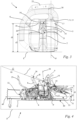
- Fig. 1
- eine schematische Seitenansicht eines als Motorkettensäge ausgebildeten Arbeitsgeräts,
- Fig. 2
- eine schematische Draufsicht von oben auf das Arbeitsgerät aus
Fig. 1 , - Fig. 3
- eine Ansicht auf das hintere Ende des Gehäuses des Arbeitsgeräts aus den
Figuren 1 und 2 , - Fig. 4
- eine schematische Schnittdarstellung eines Schnitts entlang der in
Fig. 2 eingezeichneten Schnittfläche IV-IV, - Fig. 4a
- ein vergrößertes Detail aus
Fig. 4 , - Fig. 5
- eine schematische Seitenansicht eines als Heckenschneider ausgebildeten Arbeitsgeräts, und
- Fig. 6
- eine schematische Seitenansicht eines als Trennschleifer ausgebildeten Arbeitsgeräts.
- Die
Fig. 1 bis 6 zeigen handgeführte Arbeitsgeräte 1. Die handgeführten Arbeitsgeräte 1 sind akkubetrieben. In den Ausführungsbeispielen nach denFig. 1 bis 4a ist das handgeführte Arbeitsgerät 1 eine Motorkettensäge. Im Ausführungsbeispiel nachFig. 5 ist das handgeführte Arbeitsgerät 1 eine Heckenschere. Im Ausführungsbeispiel nachFig. 6 ist das handgeführte Arbeitsgerät 1 ein Trennschleifer. Die nachfolgende Beschreibung trifft grundsätzlich auf alle Ausführungsbeispiele zu. Sollte eine Angabe sich lediglich auf eines der drei Ausführungsbeispiele beziehen, so ist dies explizit angegeben. - Das Arbeitsgerät 1 ist im bestimmungsgemäßen Betrieb handgeführt. Das Arbeitsgerät 1 ist ein tragbares Arbeitsgerät. Der Begriff "tragbar" ist in diesem Zusammenhang so zu verstehen, dass das Arbeitsgerät im bestimmungsgemäßen Betrieb getragen werden kann. Während des Betriebs des Arbeitsgeräts 1 ist es nicht erforderlich, dass das Arbeitsgerät 1 durch eine Vorrichtung oder ein Werkstück abgestützt wird. Das Arbeitsgerät 1 kann im bestimmungsgemäßen Betrieb durch den Bediener allein getragen werden.
- Das Arbeitsgerät 1 umfasst ein Gehäuse 40. Das Arbeitsgerät 1 umfasst ein Werkzeug 39. Das Werkzeug 39 ist an dem Gehäuse 40 angeordnet. Im Ausführungsbeispiel ist das Werkzeug 39 an dem Gehäuse 40 befestigt. Im Ausführungsbeispiel nach den
Fig. 1 bis 4a ist das Werkzeug durch eine Führungsschiene 5 und eine Sägekette 6 gebildet. Im Ausführungsbeispiel nachFig. 5 ist das Werkzeug 39 durch einen Messerbalken gebildet. Im Ausführungsbeispiel nachFig. 6 ist das Werkzeug 39 durch ein Sägeblatt gebildet. - Das Arbeitsgerät 1 umfasst einen Elektromotor 4. Der Elektromotor 4 dient zum Antrieb des Werkzeugs 39. Im Ausführungsbeispiel nach den
Fig. 1 bis 4a wird mittels des Elektromotors 4 die Sägekette 6 um die Führungsschiene 5 umlaufend angetrieben. Der Elektromotor 4 ist in dem Gehäuse 40 angeordnet. - Das Arbeitsgerät 1 umfasst ein Griffrohr 8. Das Griffrohr 8 umgreift das Gehäuse 40 teilweise. Es kann auch vorgesehen sein, dass das Griffrohr das Gehäuse vollständig umgreift. Das Griffrohr 8 übergreift das Gehäuse 40. Im bestimmungsgemäßen Betrieb des Arbeitsgeräts 1 kann der Bediener das Griffrohr 8 von oben umgreifen. Das Griffrohr 8 ist ein Bügelgriff.
- Das Gehäuse 40 weist ein hinteres Ende 31 auf. Das hintere Ende 31 ist im Betrieb des Arbeitsgeräts 1 dem Benutzer zugewandt. Das Gehäuse 40 weist ein vorderes Ende 32 auf. Das vordere Ende 32 des Gehäuses 40 ist im bestimmungsgemäßen Betrieb des Arbeitsgeräts 1 dem Bediener abgewandt. An dem vorderen Ende 32 ist das Werkzeug 39 angeordnet. In den Ausführungsbeispielen umschließt das Gehäuse 40 einen zusammenhängenden Innenraum. Das Gehäuse 40 ist aus zwei Halbschalen ausgebildet. Die Halbschalen liegen in einer Trennebene aneinander an. Es kann aber auch vorgesehen sein, dass das Gehäuse zwei getrennt voneinander ausgebildete Innenräume umschließt. Insbesondere kann das Gehäuse ein Motorgehäuse und ein Griffgehäuse umfassen, die getrennt voneinander ausgebildet sind. In dem Motorgehäuse sind dann der Elektromotor und der Akkuschacht angeordnet. Das Motorgehäuse und das Griffgehäuse können über einen Schwingspalt und den Schwingspalt überbrückende Antivibrationselemente miteinander verbunden sein. In diesem Fall umfasst das Gehäuse vier Halbschalen.
- Das Gehäuse 40 umfasst in jedem Fall einen Bedienbereich 2. Der Bedienbereich 2 ist dem hinteren Ende 31 des Gehäuses 40 zugeordnet. Im Bedienbereich 2 ist ein Bedienelement 15 angeordnet. Das Bedienelement 15 dient zur Bedienung des Elektromotors 4 des Arbeitsgeräts 1.
- Wie insbesondere in den
Fig. 1 und 2 dargestellt, erstreckt sich das Gehäuse 40 entlang einer Längsachse 49. Die Längsachse 49 erstreckt sich von dem hinteren Ende 31 des Gehäuses 40 zu dem vorderen Ende 32 des Gehäuses 40. Die Längsachse 49 verläuft in allen Ausführungsbeispielen parallel zu einer Werkzeugebene. In den Ausführungsbeispielen nach denFig. 1 bis 4a verläuft die Längsachse 49 parallel zur Ebene der Führungsschiene 5. Im Ausführungsbeispiel nachFig. 5 verläuft die Längsachse 49 parallel zur Ebene, in der sich die Messerbalken hin und her bewegen. Im Ausführungsbeispiel nachFig. 6 verläuft die Längsachse 49 parallel zur Ebene des Sägeblatts. Die Längsachse 49 kann auch als Längsmittelachse des Gehäuses 40 bezeichnet werden. - Das Arbeitsgerät 1 ist so ausgelegt, dass es in einer dafür vorgesehenen Abstellposition auf einer Horizontalebene E abstellbar ist. Es kann vorgesehen sein, dass das Arbeitsgerät 1 eine Abstellfläche zum Abstellen des Arbeitsgeräts 1 in der Abstellposition aufweist. In den Ausführungsbeispielen weist das Arbeitsgerät 1 Abstellvorsprünge auf, auf denen es auf der Horizontalebene E abstellbar ist. In der Abstellposition ist das Arbeitsgerät 1 derart auf der Horizontalebene E abstellbar, dass das Griffrohr 8 vom Bediener von oben umgriffen werden kann. Auf diese Weise kann das Arbeitsgerät 1 schnell und einfach angehoben und aufgenommen werden. Die Horizontalebene E verläuft in der Horizontalen. In der Abstellposition verläuft die Längsachse 49 parallel zur Horizontalebene E.
- Das Arbeitsgerät 1 besitzt eine Längsebene F. In der Abstellposition verläuft die Längsebene F senkrecht zur Horizontalebene E. Die Längsebene F enthält die Längsachse 49. Die Längsebene F wird auch als Längsmittelebene bezeichnet. Es kann vorgesehen sein, dass sich das Gehäuse 40 entlang der Längsebene F aus zwei Gehäusehälften zu dem Gehäuse 40 zusammengesetzt ist. In diesem Fall wird die Längsebene F als Trennebene des Gehäuses 40 oder als Teilungsebene des Gehäuses 40 bezeichnet. In den Ausführungsbeispielen nach den
Fig. 1 bis 4a verläuft die Längsebene F parallel zur Ebene der Führungsschiene 5. Im Ausführungsbeispiel nachFig. 5 verläuft die Längsebene F senkrecht zur Ebene, in der sich die Messerbalken gegeneinander bewegen. Im Ausführungsbeispiel nachFig. 6 verläuft die Längsebene F parallel zur Ebene des Sägeblatts. - Das Gehäuse 40 weist eine Grifföffnung 33 auf. Die Grifföffnung 33 ist im Bedienbereich 2 des Gehäuses 40 angeordnet. Die Grifföffnung 33 durchdringt das Gehäuse 40 vollständig. Die Grifföffnung 33 durchdringt das Gehäuse 40 in Richtung quer zur Längsebene F. Die Grifföffnung 33 durchdringt das Gehäuse 40 im Ausführungsbeispiel in Richtung senkrecht zur Längsebene F. Die Grifföffnung 33 weist einen in den
Fig. 1 und4 dargestellten Abstandspunkt P auf. Der Abstandspunkt P ist am Rand der Grifföffnung 33 angeordnet. Der Abstandspunkt P weist den größten in Richtung der Längsachse 49 gemessenen Abstand zu dem hinteren Ende 31 des Gehäuses 40 auf. Der Abstandspunkt P ist der Punkt der Grifföffnung 33, der zu dem hinteren Ende 31 des Gehäuses 40 den größten in Richtung der Längsachse 49 gemessenen Abstand d3 aufweist. - Der Bedienbereich 2 des Gehäuses 40 erstreckt sich in Richtung der Längsachse 49 von dem hinteren Ende 31 des Gehäuses 40 bis zu dem Abstandspunkt P. In dem Bedienbereich 2 ist von dem Gehäuse 40 ein Handgriff 22 ausgebildet. Im Bedienbereich 2 kann der Handgriff 22 von dem Benutzer umgriffen werden. Hierzu kann der Benutzer die Hand durch die Grifföffnung 33 stecken.
- Das Gehäuse 40 weist einen Frontbereich 3 auf. Der Frontbereich 3 ist in Richtung der Längsachse 49 zwischen dem Abstandspunkt P und dem vorderen Ende 32 des Gehäuses 40 angeordnet. In den Ausführungsbeispielen erstreckt sich der Frontbereich 3 des Gehäuses 40 in Richtung der Längsachse 49 von dem Abstandspunkt P der Grifföffnung 33 bis zu dem vorderen Ende 32 des Gehäuses 40. In den Ausführungsbeispielen ist das Gehäuse 2 ausschließlich in den Bedienbereich 2 und den Frontbereich 3 unterteilt.
- Das Arbeitsgerät 1 umfasst einen Akkuschacht 7. Der Akkuschacht 7 ist durch das Gehäuse 40 ausgebildet. Der Akkuschacht 7 ist in dem Frontbereich 3 des Gehäuses 40 angeordnet. Der Akkuschacht 7 ist von einer Außenseite des Gehäuses 40 begrenzt. Das Arbeitsgerät 1 ist vorzugsweise so ausgelegt, dass der Akkuschacht 7 einen in den Akkuschacht 7 eingeführten, nicht dargestellten Akkupack bezüglich einer Umfangsrichtung um die Einführrichtung 50 umschließt, so dass lediglich eine Stirnseite des Akkupacks von außerhalb des Akkuschachts 7 sichtbar ist.
- Das Gehäuse 40 besitzt eine beispielsweise in
Fig. 4 dargestellte gedachte Tangentialebene T. Die gedachte Tangentialebene T tangiert das Gehäuse 40 lediglich. Die gedachte Tangentialebene T liegt an dem Gehäuse 40 lediglich an. Die gedachte Tangentialebene T schneidet das Gehäuse 40 nicht. Die gedachte Tangentialebene T verläuft senkrecht zu der Längsebene F. Die gedachte Tangentialebene T tangiert das Griffrohr 8. Das Griffrohr 8 ist kein Bestandteil des Gehäuses 40. In allen Ausführungsbeispielen tangiert die gedachte Tangentialebene T des Gehäuses 40 das Gehäuse 40 im Bedienbereich 2 des Gehäuses 40. Die gedachte Tangentialebene T schneidet das Griffrohr 8 nicht. Die gedachte Tangentialebene T liegt an dem Griffrohr 8 an. - Das Griffrohr 8 übergreift das Gehäuse 40 derart, dass das Griffrohr 8 die Längsebene F durchkreuzt, wie in
Fig. 3 dargestellt. Das Griffrohr 8 wird auch als Bügelgriff bezeichnet. Das Griffrohr 8 ist im Frontbereich 3 des Gehäuses 40 angeordnet. Das Griffrohr 8 ist an dem Gehäuse 40 angeordnet, in den Ausführungsbeispielen befestigt. Das Griffrohr 8 ist mit seinen beiden Längsenden mit dem Gehäuse 40, im Ausführungsbeispiel mit dem Frontbereich 3 des Gehäuses 40 verbunden. Bezüglich der Richtung der Längsachse 49 ist der Akkuschacht 7 zwischen dem Griffrohr 8 und dem Bedienbereich 2 des Gehäuses 40 angeordnet. - Wie in
Fig. 4 dargestellt, besitzt die Tangentialebene T eine erste Seite 11 und eine zweite Seite 12. Die erste Seite 11 der gedachten Tangentialebene T ist in der Abstellposition des Arbeitsgeräts 1 der Horizontalebene E zugewandt. Der Frontbereich 3 des Gehäuses 40 ist ausschließlich auf der ersten Seite 11 der gedachten Tangentialebene T angeordnet. Die gedachte Tangentialebene T schneidet den Frontbereich 3 nicht. Der Frontbereich 3 durchstößt die gedachte Tangentialebene T nicht. Der Akkuschacht 7 ist ausschließlich auf der ersten Seite 11 der gedachten Tangentialebene T angeordnet. Die gedachte Tangentialebene T schneidet den Akkuschacht 7 nicht. Der Akkuschacht 7 durchstößt die Tangentialebene T nicht. - Der Frontbereich 3 weist zu der gedachten Tangentialebene T einen Frontbereichabstand m auf, wie in
Fig. 4 und inFig. 4a beispielhaft für alle Ausführungsbeispiele eingezeichnet. Der Akkuschacht 7 weist zu der gedachten Tangentialebene T den Frontbereichabstand m auf, wie inFig. 4 undFig. 4a beispielhaft für alle Ausführungsbeispiele eingezeichnet. Der Frontbereichabstand m ist senkrecht zu der gedachten Tangentialebene T gemessen. Der Frontbereichabstand m entspricht dem Abstand des Frontbereichs 3 des Gehäuses 40 von der gedachten Tangentialebene T. Der Frontbereichabstand m ist so gewählt und das Arbeitsgerät 1 ist so ausgelegt, dass der Frontbereich 3 des Gehäuses 40 bei einem Aufprall des Arbeitsgeräts 1 mit der gedachten Tangentialebene T auf der Horizontalebene E die Horizontalebene E kontaktieren kann. Der Frontbereichabstand m ist im Ausführungsbeispiel so gewählt und das Arbeitsgerät 1 ist so ausgelegt, dass der Akkuschacht 7 bei einem Aufprall des Arbeitsgeräts 1 mit der gedachten Tangentialebene T auf der Horizontalebene E die Horizontalebene E kontaktieren kann. Bei einem solchen Aufprall des Arbeitsgeräts 1 mit der gedachten Tangentialebene T auf der Horizontalebene E kann sich das Arbeitsgerät 1 elastisch derart verformen, dass das Arbeitsgerät 1 an drei Stellen die Energie des Aufpralls aufnehmen kann. Zu diesen drei Stellen zählen das Griffrohr 8, der Frontbereich 3und der Bedienbereich 2 des Gehäuses 40. Die Stelle im Frontbereich 3 des Gehäuses 40 ist insbesondere der Akkuschacht 7. - Bei einem hypothetischen Aufprall des Arbeitsgeräts 1 mit der Tangentialebene T auf der Horizontalebene E wird angenommen, dass die Normalen der Tangentialebene T und der Horizontalebene E in dieselbe Richtung zeigen. Bei einem solchen hypothetischen Aufprall des Arbeitsgeräts 1 auf der Horizontalebene E kontaktiert das Arbeitsgerät 1 die Horizontalebene E zuerst mit dem Bedienbereich 2 des Gehäuses 40 und dem Griffrohr 8. Aufgrund einer elastischen Verformung des Arbeitsgeräts 1 kommt danach auch ein Kontakt zwischen dem Frontbereich 3, in den Ausführungsbeispielen zwischen dem Akkuschacht 7 und der Horizontalebene E zustande. Dann stützt sich das Arbeitsgerät 1 mit drei Stellen gegenüber der Horizontalebene E ab. Die Energie des Aufpralls kann an drei Stellen vom Arbeitsgerät 1 aufgenommen werden. Das Arbeitsgerät 1 ist so ausgelegt, dass die Lageenergie des Arbeitsgeräts 1 in einer Höhe von 1 m über der Horizontalebene E für die beschriebene elastische Verformung des Arbeitsgeräts 1 ausreicht. Um die beschriebene elastische Verformung während eines Aufpralls des Arbeitsgeräts 1 zu ermöglichen, sind die Materialien des Arbeitsgeräts 1, insbesondere die Materialien des Griffrohrs 8 und des Gehäuses 40, entsprechend gewählt und ist die Form des Arbeitsgeräts 1 entsprechend gestaltet. In den Ausführungsbeispielen ist das Gehäuse 40, insbesondere der Bedienbereich 2 des Gehäuses 40, aus Kunststoff. Das Gehäuse 40 ist aus Spritzgussteilen, in den Ausführungsbeispielen aus zwei Halbschalen, zusammengesetzt. Das Griffrohr 8 ist aus Kunststoff. Es kann auch vorgesehen sein, dass das Griffrohr einen rohrförmigen Kern aus Metall, insbesondere aus Aluminium besitzt. In diesem Fall kann das Griffrohr von Kunststoff ummantelt sein.
- In einem realistischeren Aufprallszenario kommt das Arbeitsgerät 1 entweder zuerst mit dem Bedienbereich 2 des Gehäuses 40 oder mit dem Griffrohr 8 auf der Horizontalebene E auf. Anschließend findet dann eine Rotationsbewegung des Arbeitsgeräts 1 um eine Rotationsachse parallel zur Horizontalebene E statt, so dass das Arbeitsgerät 1 die Horizontalebene E dann mit dem Griffrohr 8 oder dem Bedienbereich 2 des Gehäuses 40 kontaktiert, je nachdem welcher der beiden Bereiche die Horizontalebene E nicht zuerst kontaktiert hat. Es kann auch passieren, dass das Arbeitsgerät 1 nach der Rotation bei dem ersten Kontakt des Bereichs, der die Horizontalebene E nicht zuerst kontaktiert hat, mit der Horizontalebene E, die Horizontalebene E im gleichen Zeitpunkt mit dem Bedienbereich 2 des Gehäuses 40 und dem Griffrohr 8 kontaktiert. In der Folge wird das Arbeitsgerät 1 derart elastisch verformt, dass es auch mit dem Akkuschacht 7 an der Horizontalebene E anliegt. Auch in diesem Aufprallszenario wird die Energie dann an drei Stellen in das Arbeitsgerät 1 eingeleitet.
- Das Arbeitsgerät 1 weist bei der Ausführung nach den
Figuren 1 bis 4 einen Handschutzbügel 25 auf. Der Handschutzbügel 25 ist nicht Bestandteil des Gehäuses 40. Der Handschutzbügel 25 ist schwenkbar am Gehäuse 40 gelagert. Der Handschutzbügel 40 kann über die gedachte Tangentialebene T hervorstehen. Bei einem Aufprall des Arbeitsgeräts 1 mit der gedachten Tangentialebene T auf die Horizontalebene kann der Handschutzbügel 25 verschwenkt werden. Durch die Ausweichbewegung des Handschutzbügels 25 bei einem solchen Aufprall ist der Handschutzbügel 25 vor einer Beschädigung geschützt. Der Handschutzbügel 25 steht im Ausführungsbeispiel nach denFig. 1 bis 4a vorteilhaft mit einer nicht dargestellten Bremse des Elektromotors 4 der Arbeitsgeräts 1 in Wirkverbindung. - Im Ausführungsbeispiel nach
Fig. 6 weist das Arbeitsgerät 1 eine Schutzhaube 34 auf. Die Schutzhaube 34 umgibt das Werkzeug 39 zumindest teilweise. Dadurch ist der Bediener vor dem Werkzeug 39 und vor geschnittenem Material geschützt. Die Schutzhaube 34 ist nicht Bestandteil des Gehäuses 40. In der schematischen Darstellung nachFig. 6 steht die Schutzhaube 34 über die Tangentialebene T hervor. Tatsächlich ist die Schutzhaube aber nur auf der ersten Seite 11 der gedachten Tangentialebene angeordnet. - Wie insbesondere in
Fig. 4 undFig. 4a dargestellt, tangiert die erste Tangentialebene T den Bedienbereich 2 des Gehäuses 40 in der Abstellposition in einer Seitenansicht senkrecht auf die Längsebene F bei allen Ausführungsbeispielen in einem Berührpunkt 10. Der Berührpunkt 10 besitzt zu der Horizontalebene E den Abstand d1. Der insbesondere inFig. 4a dargestellte Frontbereichabstand m ist kleiner als 10% des beispielsweise inFig. 4 dargestellten Abstands d1 des Berührpunkts 10 zu der Horizontalebene E. Insbesondere ist der Frontbereichabstand m kleiner als 3% des Abstands d1 des Berührpunkts 10 zu der Horizontalebene E. In den Ausführungsbeispielen ist der Frontbereichabstand m kleiner als 3% des Abstands d1 des Berührpunkts 10 zu der Horizontalebene E. Es kann auch vorgesehen sein, dass der Frontbereichabstand m 0% des Abstands d1 des Berührpunkts 10 zu der Horizontalebene E beträgt. In diesem Fall tangiert die gedachte Tangentialebene T den Bedienbereich 3. In den Ausführungsbeispielen tangiert die gedachte Tangentialebene T den Akkuschacht 7. - Das Gehäuse 40 besitzt einen Aufprallvorsprung 9. Der Aufprallvorsprung 9 des Gehäuses 40 ist im Frontbereich 3 des Gehäuses 40 angeordnet. Der Aufprallvorsprung 9 ist von dem Frontbereich 3 des Gehäuses 40 ausgebildet. Der Aufprallvorsprung 9 steht in Richtung auf die gedachte Tangentialebene T hervor. Der Aufprallvorsprung 9 ist ein Vorsprung des Frontbereichs 3 des Gehäuses 40. Der Aufprallvorsprung 9 ist bezüglich der Richtung der Längsachse 49 beidseitig von Bereichen des Gehäuses 40 begrenzt, die einen größeren Abstand zu der Tangentialebene T aufweisen als der Aufprallvorsprung 9. Der Frontbereich 3 weist im Bereich des Aufprallvorsprungs 9 den kleinsten Abstand zur gedachten Tangentialebene T auf. Der Frontbereich 3 weist im Bereich des Aufprallvorsprungs 9 den Frontbereichabstand m zur Tangentialebene T auf. Der Aufprallvorsprung 9 besitzt zur gedachten Tangentialebene T den Frontbereichabstand m. Der Aufprallvorsprung 9 ist ausschließlich auf der ersten Seite 11 der gedachten Tangentialebene T angeordnet. Der Aufprallvorsprung 9 besitzt eine Aufprallfläche 24. Die Aufprallfläche 24 verläuft in den Ausführungsbeispielen parallel zu der gedachten Tangentialebene T. Bei einem Aufprall des Arbeitsgeräts 1 mit der Tangentialebene T auf die Horizontalebene E kann der Aufprallvorsprung 9 mit der Aufprallfläche 24 zumindest kurzzeitig flächig an der Horizontalebene E anliegen und sich so abstützen. Dabei kann Energie in das Gehäuse 40 eingeleitet werden.
- Der Aufprallvorsprung 9 ist bezüglich der Richtung der Längsachse 49 zwischen dem Griffrohr 8 und dem Bedienbereich 2 des Gehäuses 40 angeordnet. Der Aufprallvorsprung 9 ist bezüglich der Richtung der Längsachse 49 näher zu dem Bedienbereich 2 des Gehäuses 2 als zu dem Griffrohr 8 angeordnet. Die gedachte Tangentialebene T liegt in einem Anlagepunkt 30 an dem Griffrohr 8 an. Die gedachte Tangentialebene T tangiert das Griffrohr 8 in dem Anlagepunkt 30. Bezüglich der Richtung der Längsachse 49 ist der Aufprallvorsprung 9 näher an dem Bedienbereich 2 des Gehäuses 40 als an dem Anlagepunkt 30 des Griffrohrs 8 angeordnet. Ein in Richtung der Längsachse 49 gemessener Abstand zwischen dem Aufprallvorsprung 9 und dem Anlagepunkt 30 der Tangentialebene T an dem Griffrohr 8 ist mindestens doppelt so groß wie der in Richtung der Längsachse 49 gemessene Abstand zwischen dem Aufprallvorsprung 9 und dem Abstandspunkt P der Grifföffnung 33.
- Der Frontbereich 3 lässt sich bezüglich der Richtung der Längsachse 49 in einen Akkubereich 36 und einen Bügelbereich 37 unterteilen, wie beispielhaft für alle Ausführungsbeispiele in
Fig. 2 dargestellt. Der Bügelbereich 37 ist dem vorderen Ende 32 des Gehäuses 40 zugeordnet. Der Akkubereich 36 ist bezüglich der Richtung der Längsachse 49 zwischen dem Bügelbereich 37 und dem Bedienbereich 2 angeordnet. Der Akkubereich 36 grenzt an den Bedienbereich 2 an. Der Akkubereich 36 grenzt an den Bügelbereich 37 an. Das Griffrohr 8 ist in den Ausführungsbeispielen vollständig im Bügelbereich 37 angeordnet. Im Bügelbereich 37 ist das Griffrohr 8 mit dem Gehäuse 40 verbunden. Der Akkuschacht 7 ist in den Ausführungsbeispielen vollständig im Akkubereich 36 angeordnet. - Der Bedienbereich 2 erstreckt sich von 35% bis 45% der in Richtung der Längsachse 49 gemessenen Gesamterstreckung des Gehäuses 40. Der Frontbereich 3 erstreckt sich von 55% bis 65% der in Richtung der Längsachse 49 gemessenen Gesamterstreckung des Gehäuses 40. Der Akkubereich 36 erstreckt sich von 20% bis 30% der in Richtung der Längsachse 49 gemessenen Gesamterstreckung des Gehäuses 40. Der Bügelbereich 37 erstreckt sich von 30% bis 40% der in Richtung der Längsachse 49 gemessenen Gesamterstreckung des Gehäuses 40.
- Der Anlagepunkt 30 des Griffrohrs 30 an der Tangentialebene T ist im Bügelbereich 37 angeordnet. Der Berührpunkt 10 ist im Bedienbereich 2 angeordnet. Die in
Fig. 4a dargestellte Aufprallfläche 24 ist im Akkubereich 36 angeordnet. - Bei dem beschriebenen Aufprall liegt das Arbeitsgerät 1 zunächst im Bügelbereich 37 mit dem Berührpunkt 30 (der auch eine entlang einer Achse ausgedehnte Stelle sein kann) des Griffrohrs 8 und im Bedienbereich 2 mit dem Berührpunkt 10 (der auch eine entlang einer Achse ausgedehnte Stelle sein kann) an der Horizontalebene E an (
Fig. 4 ). Nach der elastischen Verformung des Arbeitsgeräts 1 liegt das Arbeitsgerät 1 zusätzlich im Akkubereich 36 mit der inFig. 4a dargestellten Aufprallfläche 24 an der Horizontalebene E an. Bei diesem Aufprall bilden der Berührpunkt 10, die Aufprallfläche 24 und der Anlagepunkt 30 Stützpunkte bzw. Stützstellen für die Einleitung von Energie in das Arbeitsgerät 1. - Der Aufprallvorsprung 9 ist Teil des Akkuschachts 7. Der Akkuschacht 7 ist so ausgebildet, dass er den darin einführbaren Akku umschließen kann. Der Aufprallvorsprung 9 begrenzt den Akkuschacht 7. Der Aufprallvorsprung 9 ist von einem Rand des Akkuschachts 7 gebildet. Der Aufprallvorsprung 9 ist Teil eines geschlossen um die Einführrichtung 50 des Akkuschachts 7 umlaufenden Rands des Akkuschachts 7. Der Aufprallvorsprung 9 bildet eine Außenwand 13 des Akkuschachts 7. Der Aufprallvorsprung 9 ist zwischen einer Innenwand 23 und einer Außenwand 13 des Akkuschachts 7 angeordnet. Die Innenwand 23 des Akkuschacht ist zur Anlage an einen in den Akkuschacht 7 einführbaren Akku bestimmt. Die Aufprallfläche 24 erstreckt sich zwischen der Innenwand 23 und der Außenwand 13. Der Aufprallvorsprung 9 besitzt zu der Horizontalebene E einen größeren Abstand als der Berührpunkt 10 zwischen der Tangentialebene T und dem Bedienbereich 2 des Gehäuses 40. Der Aufprallvorsprung 9 besitzt zu der Horizontalebene E einen kleineren Abstand als der Anlagepunkt 30 der Tangentialebene T an dem Griffrohr 8. Die gedachte Tangentialebene T ist in der Abstellposition des Arbeitsgeräts 1 in Richtung von dem vorderen Ende 32 des Gehäuses 40 zu dem hinteren Ende 31 zu der Horizontalebene E hin geneigt.
- Im Ausführungsbeispiel nach den
Fig. 1 bis 4a umfasst der Frontbereich 3 des Gehäuses 40 eine Haube 36. Die Haube 36 bildet den Akkuschacht 7 zumindest teilweise. Der Aufprallvorsprung 9 ist durch die Haube 36 gebildet. Die Haube 36 umfasst zwei Halbschalen. Die beiden Halbschalen sind entlang einer Trennebene zusammengesetzt. - Das Arbeitsgerät 1 umfasst ein Betätigungselement 14. Das Betätigungselement 14 dient zum Auswerfen eines Akkus aus dem Akkuschacht 7. Das Arbeitsgerät 1 ist so gestaltet, dass das Betätigungselement 14 beim Aufprall des Arbeitsgeräts 1 durch den Aufprallvorsprung 9 geschützt ist. Dies ist insbesondere in den
Fig. 3 und 4 ersichtlich. Wie inFig. 3 erkennbar, ist der Berührpunkt 10 in den Ausführungsbeispielen eine Berührstelle, die sich entlang einer Geraden erstreckt. Lediglich in einer Seitenansicht senkrecht auf die Längsebene F ist diese Berührstelle ein Berührpunkt. In analoger Weise erstreckt sich der Aufprallvorsprung 9 entlang einer Geraden. Im Ausführungsbeispiel nachFig. 3 ist das Betätigungselement 14 zum Auswerfen des Akkus aus dem Akkuschacht 7 zwischen zwei Vorsprüngen, die den Aufprallvorsprung 9 bilden, angeordnet. Dadurch liegt das Betätigungselement 14 geschützt. Zusätzlich ist der Abstand des Betätigungselements 14 zur gedachten Tangentialebene T größer als der Abstand des Aufprallvorsprungs 9 zu der gedachten Tangentialebene T. Dies ist inFig. 4 dargestellt. - Das Arbeitsgerät 1 umfasst einen Handanschlag 16. Der Handanschlag 16 ist von dem Bedienbereich 2 des Gehäuses 40 ausgebildet. Der Handanschlag 16 dient zur Anlage der Hand eines Benutzers bei Betätigung des Bedienelements 15. Der Handanschlag 16 verhindert eine Bewegung der Hand eines Benutzers in Richtung von dem hinteren Ende 31 zu dem vorderen Ende 32 des Gehäuses 40 relativ zu dem Gehäuse 40 bei Bedienung des Bedienelements 15. Die gedachte Tangentialebene T tangiert den Bedienbereich 2 an dem Handanschlag 16.
- Im Ausführungsbeispiel ist der Handanschlag 16 als Vorsprung 17 des Bedienbereichs 2 des Gehäuses 40 ausgebildet. Der Vorsprung 17 des Bedienbereichs 2 steht in Richtung auf die Tangentialebene T vor. Der Vorsprung 17 ist bezüglich der Richtung der Längsachse 49 beidseitig von Bereichen des Gehäuses 40 begrenzt, die einen größeren Abstand zu der Tangentialebene T aufweisen als der Vorsprung 17. Der Vorsprung 17 ist höckerförmig ausgebildet. Bezüglich der Richtung der Längsachse 49 zwischen dem Vorsprung 17 des Bedienbereichs 2 und dem Aufprallvorsprung 9 des Frontbereichs 3 ist in Bezug auf die gedachte Tangentialebene T eine Vertiefung des Arbeitsgeräts 1, in den Ausführungsbeispielen des Gehäuses 40 ausgebildet.
- In den Akkuschacht 7 ist ein Akku in einer Einführrichtung 50 einführbar. Der Akku wird auch als Akkupack bezeichnet. Die Einführrichtung 50 verläuft in der Abstellposition quer zur Horizontalebene E. Die Einführrichtung 50 verläuft parallel zur Längsebene F. Es kann alternativ auch vorgesehen sein, dass die Einführrichtung quer, insbesondere senkrecht zur Längsebene F verläuft.
- Der Akkuschacht 7 weist eine Einführöffnung 18 auf. Durch die Einführöffnung 18 kann der Akku in den Akkuschacht 7 eingeführt werden. Die Einführöffnung 18 ist in der Abstellposition auf der der Horizontalebene E abgewandten Seite des Arbeitsgeräts 1 angeordnet. Die Einführöffnung 18 öffnet den Akkuschacht 7 in Richtung weg von der Horizontalebene E. Die Einführöffnung 18 besitzt einen geschlossen um die Einführrichtung 50 umlaufenden Rand. Um den Akku in den Akkuschacht 7 einzuführen, muss der Akku durch die Einführöffnung 18, insbesondere durch den geschlossen umlaufenden Rand hindurchgeführt werden. Dadurch ist der Akku sicher und geschützt gelagert.
- Vorteilhaft ist die Einführrichtung 50 in der Abstellposition in einem Winkel α von 80° bis 90° gegen die Horizontalebene E geneigt, wie in
Fig. 1 dargestellt. Es kann auch vorgesehen sein, dass die Einführrichtung 50 senkrecht auf die Horizontalebene E steht. Im Ausführungsbeispiel verläuft die Einführrichtung 50 in der Abstellposition auf die Horizontalebene E zu. In Richtung auf die Horizontalebene E zu ist die Einführrichtung 50 im Ausführungsbeispiel zu dem hinteren Ende 32 hingeneigt. Es kann aber auch vorgesehen sein, dass die Einführrichtung in Richtung auf die Horizontalebene E zu von dem hinteren Ende 33 weggeneigt ist. - Wie in den
Fig. 1 ,4 ,5 und 6 dargestellt, weist das Arbeitsgerät 1 ein weiteres Bedienelement 19 auf. Das Arbeitsgerät 1 weist ein beispielhaft für alle Ausführungsbeispiele inFig. 1 dargestelltes Sperrelement 35 auf. Das Sperrelement 35 dient zur Sperrung des Bedienelements 15 zur Bedienung des Elektromotors 4. Das Arbeitsgerät 1 ist vorteilhaft so ausgelegt, dass das Bedienelement 15 nur betätigt werden kann, wenn das Sperrelement 35 in einer Entsperrposition ist. Das Sperrelement 35 kann vom Bediener in die Entsperrposition gedrückt werden. Hierbei muss eine Federkraft überwunden werden. Damit der Bediener das Sperrelement 35 nicht permanent in die Entsperrposition gedrückt halten muss, ist das weitere Bedienelement 19 vorgesehen. Das weitere Bedienelement 19 ist in den Ausführungsbeispielen ein Halteelement. Mit dem Halteelement kann das Sperrelement 35 komfortabel in der Entsperrposition gehalten werden. Bei betätigtem Halteelement ist ein Drücken des Sperrelements 35 in die Entsperrposition nicht mehr dauerhaft, sondern nur initial erforderlich. Nach initialem Drücken des Sperrelements 35 in die Entsperrposition kann das Sperrelement 35 mittels (permanenter) Betätigung des Halteelements in der Entsperrposition, vorzugsweise mechanisch, gehalten werden. - Es kann auch vorgesehen sein, dass das weitere Bedienelement 19 ein Sperrelement ist. Vorzugsweise steht das weitere Bedienelement 19 in der Abstellposition in Richtung weg von der Horizontalebene E aus dem Bedienbereich 2 des Gehäuses 40 hervor. Das weitere Bedienelement ist kein Bestandteil des Gehäuses 40.
- Das weitere Bedienelement 19 ist im Bedienbereich 2 des Gehäuses 40 angeordnet. Das Arbeitsgerät 1 umfasst eine Bedienelementöffnung 21. Die Bedienelementöffnung 21 ist im Gehäuse 40 angeordnet. Die Bedienelementöffnung 21 durchdringt eine Außenwand des Gehäuses 40 vollständig. Die Bedienelementöffnung 21 ist im Bedienbereich 2 des Gehäuses 40 angeordnet. Die Bedienelementöffnung 21 ist in der Abstellposition auf der der Horizontalebene E abgewandten Seite des Arbeitsgeräts 1 angeordnet. Das weitere Bedienelement 19 ragt aus der Bedienelementöffnung 21 hervor.
- Der Berührpunkt 10 des Bedienbereichs 2 mit der gedachten Tangentialebene T liegt bezüglich der Richtung der Längsachse 49 zwischen dem weiteren Bedienelement 19 und dem Frontbereich 3.
- Der Berührpunkt 10 des Bedienbereichs 2 mit der gedachten Tangentialebene T liegt bezüglich der Richtung der Längsachse 49 zwischen der Bedienelementöffnung 21 und dem Frontbereich 3.
- Die Bedienelementöffnung 21 weist in einer Seitenansicht senkrecht auf die Längsebene F einen Tiefpunkt 20 auf, wie beispielsweise in
Fig. 4 dargestellt. Der Tiefpunkt 20 ist in der Seitenansicht senkrecht auf die Längsebene F der Punkt der Bedienelementöffnung 21 mit dem kleinsten Abstand d2 zu der Horizontalebene E. Wie ausFig. 3 ersichtlich, ist der Tiefpunkt 20 lediglich in der Seitenansicht senkrecht auf die Längsebene F punktförmig. Tatsächlich handelt es sich bei dem Tiefpunkt 20 um eine Tiefstelle, die sich entlang einer Geraden erstreckt. Wie inFig. 4 dargestellt, verläuft eine gedachte Berührebene B senkrecht zur Längsebene F. Die gedachte Berührebene B verläuft durch den Tiefpunkt 20. Die gedachte Berührebene B tangiert den Akkuschacht 7. Im Gegensatz zur gedachten Tangentialebene T schneidet die gedachte Berührebene B das Gehäuse 40. Der Handanschlag 16 steht über die gedachte Berührebene B hervor. - Die gedachte Berührebene B schneidet den Handanschlag 16.
- Die Bedienelementöffnung 21 ist in der Abstellposition auf der der Horizontalebene E abgewandten Seite des Griffgehäuses 2 angeordnet. Im Ausführungsbeispiel ist das weitere Bedienelement 19 als Hebel ausgebildet. Das weitere Bedienelement 19 ist im Ausführungsbeispiel mit einer Feder vorgespannt. Die Vorspannung des weiteren Bedienelements 19 wirkt in der Abstellposition des Arbeitsgeräts 1 in Richtung weg von der Horizontalebene E.
- Die gedachte Berührebene B tangiert die Außenwand 13 des Akkuschachts 7. Die Berührebene B tangiert den Aufprallvorsprung 9.
- Die Berührebene B schneidet den Vorsprung 17. Der Handanschlag 16 ist an dem Vorsprung 17 ausgebildet. Der Handanschlag 16 ist bezüglich der Richtung der Längsachse 49 zwischen dem Tiefpunkt 20 und dem Akkuschacht 7 angeordnet. Der Handanschlag 16 ist bezüglich der Richtung der Längsachse 49 zwischen der Außenwand 13 des Akkuschachts 7 und dem Tiefpunkt 20 angeordnet. Der Handanschlag 16 ist bezüglich der Richtung der Längsachse 49 zwischen dem Aufprallvorsprung 9 und dem Tiefpunkt 20 angeordnet.
- In den Ansichten nach den
Fig. 5 und 6 ist kein Betätigungselement 14 erkennbar. Analog zum Ausführungsbeispiel nach denFig. 1 bis 4 ist aber ein Betätigungselement 14 vorhanden. - Im Ausführungsbeispiel nach
Fig. 6 ist kein Handanschlag gezeigt. Analog zu den Ausführungsbeispielen nach denFig. 1 bis 5 kann aber auch bei dem Trennschleifer nachFig. 6 ein Handanschlag vorgesehen sein. InFig. 6 ist aber eine Vorsprung 17 gezeigt, an dem die Tangentialebene T anliegt. Die Berührebene B schneidet den Vorsprung 17.
Claims (15)
- Handgeführtes, akkubetriebenes Arbeitsgerät, wobei das Arbeitsgerät (1) insbesondere eine Motorkettensäge, eine Heckenschere oder ein Trennschleifer ist, wobei das Arbeitsgerät (1) ein Gehäuse (40) und ein daran angeordnetes Werkzeug (39) aufweist, wobei das Arbeitsgerät (1) ein Griffrohr (8) umfasst, das das Gehäuse (40) zumindest teilweise umgreift, insbesondere übergreift, wobei das Gehäuse (40) ein hinteres Ende (31) aufweist, dem ein Bedienbereich (2) des Gehäuses (40) zugeordnet ist, wobei das Gehäuse (40) ein vorderes Ende (32) aufweist, an dem das Werkzeug (39) angeordnet ist, wobei sich das Gehäuse (40) entlang einer Längsachse (49) von dem hinteren Ende (31) zu dem vorderen Ende (32) erstreckt, wobei im Bedienbereich (2) ein Bedienelement (15) zur Bedienung eines Elektromotors (4) des Arbeitsgeräts (1) angeordnet ist, wobei das Arbeitsgerät (1) so ausgelegt ist, dass es in einer dafür vorgesehenen Abstellposition auf einer Horizontalebene (E) abstellbar ist, wobei das Arbeitsgerät (1) eine Längsebene (F) besitzt, die in der Abstellposition senkrecht zur Horizontalebene (E) verläuft und die Längsachse (49) enthält, wobei der Bedienbereich (2) eine das Gehäuse (40) in Richtung quer zur Längsebene (F) vollständig durchdringende Grifföffnung (33) aufweist, wobei die Grifföffnung (33) in Richtung der Längsachse (49) einen Abstandspunkt (P) mit dem in Richtung der Längsachse (49) gemessenen größten Abstand zu dem hinteren Ende (31) des Gehäuses (40) aufweist, wobei sich der Bedienbereich (2) des Gehäuses (40) in Richtung der Längsachse (49) von dem hinteren Ende (31) des Gehäuses (40) bis zu dem Abstandspunkt (P) erstreckt, wobei das Gehäuse (40) einen Frontbereich (3) aufweist, wobei sich der Frontbereich (3) in Richtung der Längsachse (49) von dem Abstandspunkt (P) bis zu dem vorderen Ende (32) des Gehäuses (40) erstreckt, wobei das Gehäuse (40) eine gedachte Tangentialebene (T) besitzt, die das Gehäuse (40) lediglich tangiert, wobei die gedachte Tangentialebene (T) senkrecht zu der Längsebene (F) verläuft, wobei die gedachte Tangentialebene (T) das Griffrohr (8) tangiert,
dadurch gekennzeichnet, dass die gedachte Tangentialebene (T) das Gehäuse (40) im Bedienbereich (2) des Gehäuses (40), insbesondere in einem Berührpunkt (10) tangiert. - Arbeitsgerät nach Anspruch 1,
dadurch gekennzeichnet, dass die Tangentialebene (T) eine erste Seite (11) und eine zweite Seite (12) besitzt, dass die erste Seite (11) in der Abstellposition der Horizontalebene (E) zugewandt ist, und dass der Frontbereich (3) des Gehäuses (40) ausschließlich auf der ersten Seite (11) der gedachten Tangentialebene (T) angeordnet ist. - Arbeitsgerät nach Anspruch 1 oder 2,
dadurch gekennzeichnet, dass der Frontbereich (3) zu der gedachten Tangentialebene (T) einen Frontbereichabstand (m) aufweist, dass der Frontbereichabstand (m) so klein gewählt ist und dass das Arbeitsgerät (1) so ausgelegt ist, dass der Frontbereich (3) des Gehäuses (40) bei einem Aufprall des Arbeitsgeräts (1) mit der gedachten Tangentialebene (T) auf der Horizontalebene (E), die Horizontalebene (E) kontaktieren kann. - Arbeitsgerät nach Anspruch 3,
dadurch gekennzeichnet, dass der Frontbereichabstand (m) kleiner als 10%, insbesondere kleiner als 5%, insbesondere kleiner als 3%, insbesondere 0% des Abstands (d1) des Berührpunkts (10) zu der Horizontalebene (E) ist. - Arbeitsgerät nach einem der Ansprüche 1 bis 4,
dadurch gekennzeichnet, dass der Frontbereich (3) des Gehäuses (40) einen Aufprallvorsprung (9) besitzt, dass der Aufprallvorsprung (9) in Richtung auf die Tangentialebene (T) hervorsteht, und dass der Frontbereich (3) im Bereich des Aufprallvorsprungs (9) den kleinsten Abstand zur Tangentialebene (T) aufweist. - Arbeitsgerät nach einem der Ansprüche 1 bis 5,
dadurch gekennzeichnet, dass in dem Frontbereich (3) des Gehäuses (40) ein Akkuschacht (7) angeordnet ist, so dass das Gehäuse (40) einen Akku umschließen kann. - Arbeitsgerät nach den Ansprüchen 5 und 6,
dadurch gekennzeichnet, dass der Aufprallvorsprung (9) Teil des Akkuschachts (7) ist, insbesondere dass der Aufprallvorsprung (9) eine Außenwand (13) des Akkuschachts (7) bildet. - Arbeitsgerät nach Anspruch 6 oder 7,
dadurch gekennzeichnet, dass ein Akku in einer Einführrichtung (50) in den Akkuschacht (7) einführbar ist, und dass die Einführrichtung (50) parallel zur Längsebene (F) verläuft, und insbesondere dass der Akkuschacht (7) eine Einführöffnung (18) aufweist, die in der Abstellposition auf der der Horizontalebene abgewandten Seite des Arbeitsgeräts (1) angeordnet ist. - Arbeitsgerät nach einem der Ansprüche 1 bis 8,
dadurch gekennzeichnet, dass der Bedienbereich (2) einen Handanschlag (16) zur Anlage der Hand bei Betätigung des Bedienelements (15) aufweist, und dass die gedachte Tangentialebene (T) den Bedienbereich (2) an dem Handanschlag (16) tangiert, und insbesondere dass der Handanschlag (16) als Vorsprung (17) des Bedienbereichs (2) ausgebildet ist, insbesondere dass der Handanschlag (16) im Wesentlichen höckerförmig ist. - Arbeitsgerät nach einem der Ansprüche 1 bis 9,
dadurch gekennzeichnet, dass das Arbeitsgerät (1) im Bedienbereich (2) ein weiteres Bedienelement (19) aufweist, wobei das weitere Bedienelement (19) zum Entsperren des Bedienelements (15) oder zum Halten eines Sperrelements (35) in einer Entsperrposition dient, und dass der Berührpunkt (10) bezüglich der Richtung der Längsachse (49) zwischen dem weiteren Bedienelement (19) und dem Frontbereich (3) liegt. - Handgeführtes, akkubetriebenes Arbeitsgerät, wobei das Arbeitsgerät (1) insbesondere eine Motorkettensäge, eine Heckenschere oder ein Trennschleifer ist, wobei das Arbeitsgerät (1) ein Gehäuse (40) und ein daran befestigtes Werkzeug (39) aufweist, wobei das Gehäuse (40) ein hinteres Ende (31) aufweist, dem ein Bedienbereich (2) des Gehäuses (40) zugeordnet ist, wobei das Gehäuse (40) ein vorderes Ende (32) aufweist, an dem das Werkzeug (39) angeordnet ist, wobei sich das Gehäuse (40) entlang einer Längsachse (49) von dem hinteren Ende (31) zu dem vorderen Ende (32) erstreckt, wobei im Bedienbereich (2) ein Bedienelement (15) zur Bedienung eines Elektromotors (4) des Arbeitsgeräts (1) angeordnet ist, wobei das Arbeitsgerät (1) so ausgelegt ist, dass es in einer dafür vorgesehenen Abstellposition auf einer Horizontalebene (E) abstellbar ist, wobei das Arbeitsgerät (1) eine Längsebene (F) besitzt, die in der Abstellposition senkrecht zur Horizontalebene (E) verläuft und die Längsachse (49) enthält, wobei das Gehäuse (40) einen Akkuschacht (7) aufweist, wobei in dem Bedienbereich (2) des Gehäuses (40) ein weiteres Bedienelement (19) vorgesehen ist, wobei das weitere Bedienelement (19) aus einer Bedienelementöffnung (21) im Bedienbereich (2) in der Abstellposition in Richtung weg von der Horizontalebene (E) hervorragt, wobei durch das Gehäuse (40) im Bedienbereich (2) ein Handanschlag (16) zur Anlage der Hand bei Betätigung des Bedienelements (15) ausgebildet ist, wobei in der Abstellposition die Bedienelementöffnung (21) in einer Seitenansicht senkrecht auf die Längsebene (F) einen Tiefpunkt (20) aufweist, der dem Punkt der Bedienelementöffnung (21) mit dem kleinsten Abstand (d2) zu der Horizontalebene (E) entspricht, wobei eine gedachte Berührebene (B) senkrecht zur Längsebene (F) durch den Tiefpunkt (20) verläuft und den Akkuschacht (7) tangiert,
dadurch gekennzeichnet, dass der Handanschlag (16) über die gedachte Berührebene (B) hervorsteht. - Arbeitsgerät nach Anspruch 11,
dadurch gekennzeichnet, dass die Bedienelementöffnung (21) in der Abstellposition auf der der Horizontalebene (E) abgewandten Seite des Bedienbereichs (2) angeordnet ist. - Arbeitsgerät nach Anspruch 11 oder 12,
dadurch gekennzeichnet, dass der Akkuschacht (7) eine Außenwand (13) aufweist, die von der gedachten Berührebene (B) tangiert wird. - Arbeitsgerät nach einem der Ansprüche 11 bis 13,
dadurch gekennzeichnet, dass der Handanschlag (16) als Vorsprung (17) des Bedienbereichs (2) des Gehäuses (40) ausgebildet ist, insbesondere dass der Handanschlag (16) im Wesentlichen höckerförmig ist, und insbesondere dass die gedachte Berühreben (B) den Handanschlag (16) schneidet. - Arbeitsgerät nach einem der Ansprüche 11 bis 14,
dadurch gekennzeichnet, dass ein Akku in einer Einführrichtung (50) in den Akkuschacht (7) einführbar ist, und dass die Einführrichtung (50) parallel zur Längsebene (F) verläuft, insbesondere dass der Akkuschacht (7) eine Einführöffnung (18) aufweist, und insbesondere dass die Einführöffnung (18) in der Abstellposition auf der der Horizontalebene (E) abgewandten Seite des Arbeitsgeräts (1) angeordnet ist.
Priority Applications (1)
| Application Number | Priority Date | Filing Date | Title |
|---|---|---|---|
| CN202310829532.5A CN117356287A (zh) | 2022-07-07 | 2023-07-07 | 手持式的、蓄电池运行的工作器具 |
Applications Claiming Priority (1)
| Application Number | Priority Date | Filing Date | Title |
|---|---|---|---|
| DE102022116975.8A DE102022116975A1 (de) | 2022-07-07 | 2022-07-07 | Handgehaltenes Elektrowerkzeug und System mit einem handgehaltenen Elektrowerkzeug |
Publications (2)
| Publication Number | Publication Date |
|---|---|
| EP4302928A1 true EP4302928A1 (de) | 2024-01-10 |
| EP4302928B1 EP4302928B1 (de) | 2026-05-27 |
Family
ID=84421119
Family Applications (1)
| Application Number | Title | Priority Date | Filing Date |
|---|---|---|---|
| EP22211746.7A Active EP4302928B1 (de) | 2022-07-07 | 2022-12-06 | Handgeführtes, akkubetriebenes arbeitsgerät |
Country Status (4)
| Country | Link |
|---|---|
| US (2) | US12017337B2 (de) |
| EP (1) | EP4302928B1 (de) |
| CN (2) | CN117356287A (de) |
| DE (1) | DE102022116975A1 (de) |
Families Citing this family (1)
| Publication number | Priority date | Publication date | Assignee | Title |
|---|---|---|---|---|
| DE102025104458A1 (de) * | 2025-02-06 | 2026-08-06 | Einhell Germany Ag | Elektrogerät, insbesondere handgeführtes Gartengerät |
Citations (3)
| Publication number | Priority date | Publication date | Assignee | Title |
|---|---|---|---|---|
| DE102009012178A1 (de) * | 2009-02-27 | 2010-09-02 | Andreas Stihl Ag & Co. Kg | Akkubetriebenes, handgeführtes Arbeitsgerät |
| CN102416504A (zh) * | 2011-10-14 | 2012-04-18 | 浙江亚特电器有限公司 | 一种蓄电池驱动的链锯 |
| SE1951341A1 (en) * | 2019-11-25 | 2021-05-26 | Husqvarna Ab | A battery lock mechanism for a battery compartment and an electrically powered hand-held work tool comprising such a battery lock mechanism |
Family Cites Families (33)
| Publication number | Priority date | Publication date | Assignee | Title |
|---|---|---|---|---|
| JP3870798B2 (ja) * | 2002-02-19 | 2007-01-24 | 日立工機株式会社 | 打撃工具 |
| DE102006018072B4 (de) * | 2006-04-10 | 2016-08-11 | Andreas Stihl Ag & Co. Kg | Heckenschere |
| DE102009012175A1 (de) | 2009-02-27 | 2010-09-02 | Andreas Stihl Ag & Co. Kg | Elektroarbeitsgerät mit einem Akkupack |
| DE102009012181A1 (de) * | 2009-02-27 | 2010-09-02 | Andreas Stihl Ag & Co. Kg | Akkubetriebenes, handgeführtes Arbeitsgerät mit einem Gashebel |
| DE102009050547A1 (de) | 2009-10-23 | 2011-04-28 | Andreas Stihl Ag & Co. Kg | Elektrisches Arbeitsgerät mit einer Kommunikationsleitung zum Akkupack |
| CN101927480B (zh) | 2010-04-29 | 2016-08-03 | 常州格力博有限公司 | 电动工具 |
| US10105832B2 (en) * | 2010-07-02 | 2018-10-23 | Husqvarna Ab | Battery powered tool |
| DE102010045993A1 (de) | 2010-09-18 | 2012-03-22 | Andreas Stihl Ag & Co. Kg | Handgeführtes Arbeitsgerät mit einem elektrischen Antriebsmotor |
| EP2625006B1 (de) * | 2010-10-08 | 2016-12-07 | Milwaukee Electric Tool Corporation | Batteriehaltesystem für ein stromwerkzeug |
| EP2747965B2 (de) * | 2011-08-26 | 2023-09-27 | Husqvarna AB | Batteriebetriebene kettensäge mit hinterem griff |
| CN102554882B (zh) | 2012-02-28 | 2015-08-12 | 南京德朔实业有限公司 | 手持式工具 |
| DE102013202027B4 (de) * | 2013-02-07 | 2024-09-26 | Robert Bosch Gmbh | Tragbare Werkzeugmaschine mit einem Haupt- und einem Bügelgriff |
| CN103299835B (zh) | 2013-05-30 | 2014-12-24 | 江苏苏美达五金工具有限公司 | 一种便携式电动工具 |
| DE102013012746A1 (de) * | 2013-07-31 | 2015-02-05 | Andreas Stihl Ag & Co. Kg | Handgeführtes Arbeitsgerät |
| JP6300271B2 (ja) * | 2014-07-22 | 2018-03-28 | 株式会社マキタ | チェーンソー |
| JP6575793B2 (ja) * | 2014-11-18 | 2019-09-18 | パナソニックIpマネジメント株式会社 | 電動工具 |
| DE102015012043A1 (de) * | 2015-09-15 | 2017-03-16 | Andreas Stihl Ag & Co. Kg | Verfahren zur Inbetriebnahme eines handgeführten Arbeitsgerätes mit einem Elektromotor |
| US10800065B2 (en) * | 2015-12-15 | 2020-10-13 | Andreas Stihl Ag & Co. Kg | Hand-guided power tool with a control device |
| EP3181306A1 (de) * | 2015-12-17 | 2017-06-21 | HILTI Aktiengesellschaft | Akkubetriebene handwerkzeugmaschine iii |
| JP6615648B2 (ja) * | 2016-03-10 | 2019-12-04 | 株式会社マキタ | チェーンソー |
| DE102016013910A1 (de) | 2016-11-14 | 2018-05-17 | Andreas Stihl Ag & Co. Kg | Handgeführte, tragbare Schneidvorrichtung mit einer Schneidgarnitur |
| ES2947607T3 (es) * | 2017-09-27 | 2023-08-14 | Globe Jiangsu Co Ltd | Bloqueo de gatillo con acciones diferentes |
| JP6979374B2 (ja) * | 2018-02-26 | 2021-12-15 | 株式会社やまびこ | 電動作業機 |
| CN208262881U (zh) * | 2018-03-09 | 2018-12-21 | 南京德朔实业有限公司 | 电圆锯 |
| SE543764C2 (en) * | 2018-11-26 | 2021-07-13 | Husqvarna Ab | Power tool with improved liquid dispensing system |
| JP7202899B2 (ja) * | 2019-01-15 | 2023-01-12 | 株式会社やまびこ | 電動作業機 |
| IT201900004273A1 (it) * | 2019-03-25 | 2020-09-25 | Emak Spa | Attrezzo da lavoro dotato di un elemento smorzatore |
| JP7358167B2 (ja) * | 2019-09-30 | 2023-10-10 | 株式会社マキタ | 電池パック |
| EP3865250B1 (de) * | 2020-02-14 | 2022-07-06 | Andreas Stihl AG & Co. KG | Handgeführtes bearbeitungsgerät mit bedienelement und anzeigefeld |
| CN213124649U (zh) * | 2020-06-05 | 2021-05-04 | 帝亚一维新能源汽车有限公司 | 便于取放的动力电池包外壳及电池包和便携式换电电动车 |
| CN213828833U (zh) * | 2020-09-03 | 2021-07-30 | 浙江齐享科技有限公司 | 一种电动工具 |
| JP7682752B2 (ja) * | 2021-09-27 | 2025-05-26 | 株式会社マキタ | チェーンソー |
| JP7814948B2 (ja) * | 2022-01-20 | 2026-02-17 | 株式会社やまびこ | 電動作業機 |
-
2022
- 2022-07-07 DE DE102022116975.8A patent/DE102022116975A1/de active Pending
- 2022-12-06 EP EP22211746.7A patent/EP4302928B1/de active Active
- 2022-12-06 US US18/062,379 patent/US12017337B2/en active Active
-
2023
- 2023-07-06 US US18/348,154 patent/US20240009827A1/en active Pending
- 2023-07-07 CN CN202310829532.5A patent/CN117356287A/zh active Pending
- 2023-07-07 CN CN202310829531.0A patent/CN117356285A/zh active Pending
Patent Citations (3)
| Publication number | Priority date | Publication date | Assignee | Title |
|---|---|---|---|---|
| DE102009012178A1 (de) * | 2009-02-27 | 2010-09-02 | Andreas Stihl Ag & Co. Kg | Akkubetriebenes, handgeführtes Arbeitsgerät |
| CN102416504A (zh) * | 2011-10-14 | 2012-04-18 | 浙江亚特电器有限公司 | 一种蓄电池驱动的链锯 |
| SE1951341A1 (en) * | 2019-11-25 | 2021-05-26 | Husqvarna Ab | A battery lock mechanism for a battery compartment and an electrically powered hand-held work tool comprising such a battery lock mechanism |
Also Published As
| Publication number | Publication date |
|---|---|
| US12017337B2 (en) | 2024-06-25 |
| US20240009827A1 (en) | 2024-01-11 |
| DE102022116975A1 (de) | 2024-01-18 |
| US20240009826A1 (en) | 2024-01-11 |
| EP4302928B1 (de) | 2026-05-27 |
| CN117356287A (zh) | 2024-01-09 |
| CN117356285A (zh) | 2024-01-09 |
Similar Documents
| Publication | Publication Date | Title |
|---|---|---|
| EP3321049B1 (de) | Handgeführte, tragbare schneidvorrichtung mit einer schneidgarnitur | |
| EP3792008B1 (de) | Handgeführtes arbeitsgerät mit einem werkzeug | |
| DE112009000537B4 (de) | Tragbare batteriegespeiste Säbelsäge | |
| EP2223780B1 (de) | Elektroarbeitsgerät mit einem Akkupack | |
| DE102009012178B4 (de) | Akkubetriebenes, handgeführtes Arbeitsgerät | |
| DE102016111548B4 (de) | Bearbeitungsvorrichtung | |
| EP0340467A2 (de) | Sicherheitseinrichtung an einer Handwerkzeugmaschine | |
| DE102007011168B4 (de) | Handkreissäge | |
| DE102023110484A1 (de) | Tragbares schneidgerät zur metallbearbeitung | |
| WO2002070198A1 (de) | Handwerkzeugmaschine mit einer schwenkbaren werkzeugabdeckung | |
| WO2024104765A1 (de) | Schutzvorrichtung, akkuschutzelement, portables arbeitsgerät und verfahren zumindest zu einem schutz eines akkumulators | |
| DE102023212412A1 (de) | Schutzvorrichtung für zumindest einen Wechselakkupack eines batteriebetriebenen Bearbeitungsgeräts | |
| EP1708851B1 (de) | Elektrohandwerkzeug | |
| EP4059666A2 (de) | Handgeführtes arbeitsgerät mit einem führungsrohr | |
| EP4389361B1 (de) | Handgeführtes arbeitsgerät | |
| DE102010021523B4 (de) | Wippkreissäge | |
| US12017337B2 (en) | Handheld, battery-operated work apparatus | |
| DE102019117408A1 (de) | Verschiebbare Schutzverkleidung | |
| DE102022205095A1 (de) | Werkzeugmaschinenvorrichtung, Werkzeugmaschine und System | |
| WO2023227401A1 (de) | Werkzeugmaschinenvorrichtung, werkzeugmaschine und system | |
| DE102024111427B4 (de) | Handgeführtes Arbeitsgerät mit Schutzhaube | |
| DE102024115403A1 (de) | Handgeführtes Akku-Arbeitsgerät | |
| DE102022123203A1 (de) | Handgeführtes Arbeitsgerät | |
| DE202023101697U1 (de) | Tragbare Bearbeitungsmaschine | |
| DE102025121658A1 (de) | Tragbare schneidvorrichtung zum schneiden von metall und tragbare schneidvorrichtung |
Legal Events
| Date | Code | Title | Description |
|---|---|---|---|
| PUAI | Public reference made under article 153(3) epc to a published international application that has entered the european phase |
Free format text: ORIGINAL CODE: 0009012 |
|
| STAA | Information on the status of an ep patent application or granted ep patent |
Free format text: STATUS: THE APPLICATION HAS BEEN PUBLISHED |
|
| AK | Designated contracting states |
Kind code of ref document: A1 Designated state(s): AL AT BE BG CH CY CZ DE DK EE ES FI FR GB GR HR HU IE IS IT LI LT LU LV MC ME MK MT NL NO PL PT RO RS SE SI SK SM TR |
|
| STAA | Information on the status of an ep patent application or granted ep patent |
Free format text: STATUS: REQUEST FOR EXAMINATION WAS MADE |
|
| 17P | Request for examination filed |
Effective date: 20240708 |
|
| RBV | Designated contracting states (corrected) |
Designated state(s): AL AT BE BG CH CY CZ DE DK EE ES FI FR GB GR HR HU IE IS IT LI LT LU LV MC ME MK MT NL NO PL PT RO RS SE SI SK SM TR |
|
| GRAP | Despatch of communication of intention to grant a patent |
Free format text: ORIGINAL CODE: EPIDOSNIGR1 |
|
| STAA | Information on the status of an ep patent application or granted ep patent |
Free format text: STATUS: GRANT OF PATENT IS INTENDED |
|
| RIC1 | Information provided on ipc code assigned before grant |
Ipc: B25F 5/02 20060101AFI20251215BHEP Ipc: B27B 17/00 20060101ALI20251215BHEP Ipc: A01G 3/053 20060101ALI20251215BHEP Ipc: B24B 27/08 20060101ALI20251215BHEP |
|
| INTG | Intention to grant announced |
Effective date: 20260105 |
|
| GRAS | Grant fee paid |
Free format text: ORIGINAL CODE: EPIDOSNIGR3 |
|
| GRAA | (expected) grant |
Free format text: ORIGINAL CODE: 0009210 |
|
| STAA | Information on the status of an ep patent application or granted ep patent |
Free format text: STATUS: THE PATENT HAS BEEN GRANTED |
|
| AK | Designated contracting states |
Kind code of ref document: B1 Designated state(s): AL AT BE BG CH CY CZ DE DK EE ES FI FR GB GR HR HU IE IS IT LI LT LU LV MC ME MK MT NL NO PL PT RO RS SE SI SK SM TR |
|
| REG | Reference to a national code |
Ref country code: CH Ref legal event code: F10 Free format text: ST27 STATUS EVENT CODE: U-0-0-F10-F00 (AS PROVIDED BY THE NATIONAL OFFICE) Effective date: 20260527 Ref country code: GB Ref legal event code: FG4D Free format text: NOT ENGLISH |
|
| REG | Reference to a national code |
Ref country code: DE Ref legal event code: R096 Ref document number: 502022008006 Country of ref document: DE |