EP4302114B1 - Verfahren zur bestimmung einer ausbreitungsrichtung einer schallquelle durch erzeugung sinusförmiger signale aus von mikrofonen empfangenen tonsignalen - Google Patents
Verfahren zur bestimmung einer ausbreitungsrichtung einer schallquelle durch erzeugung sinusförmiger signale aus von mikrofonen empfangenen tonsignalen Download PDFInfo
- Publication number
- EP4302114B1 EP4302114B1 EP22714117.3A EP22714117A EP4302114B1 EP 4302114 B1 EP4302114 B1 EP 4302114B1 EP 22714117 A EP22714117 A EP 22714117A EP 4302114 B1 EP4302114 B1 EP 4302114B1
- Authority
- EP
- European Patent Office
- Prior art keywords
- sound
- determining
- microphones
- sound source
- audio
- Prior art date
- Legal status (The legal status is an assumption and is not a legal conclusion. Google has not performed a legal analysis and makes no representation as to the accuracy of the status listed.)
- Active
Links
Images


Classifications
-
- G—PHYSICS
- G01—MEASURING; TESTING
- G01S—RADIO DIRECTION-FINDING; RADIO NAVIGATION; DETERMINING DISTANCE OR VELOCITY BY USE OF RADIO WAVES; LOCATING OR PRESENCE-DETECTING BY USE OF THE REFLECTION OR RERADIATION OF RADIO WAVES; ANALOGOUS ARRANGEMENTS USING OTHER WAVES
- G01S3/00—Direction-finders for determining the direction from which infrasonic, sonic, ultrasonic or electromagnetic waves, or particle emission, not having a directional significance, are being received
- G01S3/80—Direction-finders for determining the direction from which infrasonic, sonic, ultrasonic or electromagnetic waves, or particle emission, not having a directional significance, are being received using ultrasonic, sonic or infrasonic waves
- G01S3/802—Systems for determining direction or deviation from predetermined direction
- G01S3/808—Systems for determining direction or deviation from predetermined direction using transducers spaced apart and measuring phase or time difference between signals therefrom, i.e. path-difference systems
- G01S3/8083—Systems for determining direction or deviation from predetermined direction using transducers spaced apart and measuring phase or time difference between signals therefrom, i.e. path-difference systems determining direction of source
-
- H—ELECTRICITY
- H04—ELECTRIC COMMUNICATION TECHNIQUE
- H04R—LOUDSPEAKERS, MICROPHONES, GRAMOPHONE PICK-UPS OR LIKE ACOUSTIC ELECTROMECHANICAL TRANSDUCERS; ELECTRIC HEARING AIDS; PUBLIC ADDRESS SYSTEMS
- H04R5/00—Stereophonic arrangements
- H04R5/04—Circuit arrangements, e.g. for selective connection of amplifier inputs/outputs to loudspeakers, for loudspeaker detection, or for adaptation of settings to personal preferences or hearing impairments
-
- H—ELECTRICITY
- H04—ELECTRIC COMMUNICATION TECHNIQUE
- H04B—TRANSMISSION
- H04B17/00—Monitoring; Testing
- H04B17/30—Monitoring; Testing of propagation channels
- H04B17/309—Measuring or estimating channel quality parameters
- H04B17/364—Delay profiles
-
- H—ELECTRICITY
- H04—ELECTRIC COMMUNICATION TECHNIQUE
- H04R—LOUDSPEAKERS, MICROPHONES, GRAMOPHONE PICK-UPS OR LIKE ACOUSTIC ELECTROMECHANICAL TRANSDUCERS; ELECTRIC HEARING AIDS; PUBLIC ADDRESS SYSTEMS
- H04R3/00—Circuits for transducers
- H04R3/005—Circuits for transducers for combining the signals of two or more microphones
-
- G—PHYSICS
- G01—MEASURING; TESTING
- G01S—RADIO DIRECTION-FINDING; RADIO NAVIGATION; DETERMINING DISTANCE OR VELOCITY BY USE OF RADIO WAVES; LOCATING OR PRESENCE-DETECTING BY USE OF THE REFLECTION OR RERADIATION OF RADIO WAVES; ANALOGOUS ARRANGEMENTS USING OTHER WAVES
- G01S1/00—Beacons or beacon systems transmitting signals having a characteristic or characteristics capable of being detected by non-directional receivers and defining directions, positions, or position lines fixed relatively to the beacon transmitters; Receivers co-operating therewith
- G01S1/72—Beacons or beacon systems transmitting signals having a characteristic or characteristics capable of being detected by non-directional receivers and defining directions, positions, or position lines fixed relatively to the beacon transmitters; Receivers co-operating therewith using ultrasonic, sonic or infrasonic waves
- G01S1/74—Details
- G01S1/75—Transmitters
- G01S1/753—Signal details
-
- G—PHYSICS
- G01—MEASURING; TESTING
- G01S—RADIO DIRECTION-FINDING; RADIO NAVIGATION; DETERMINING DISTANCE OR VELOCITY BY USE OF RADIO WAVES; LOCATING OR PRESENCE-DETECTING BY USE OF THE REFLECTION OR RERADIATION OF RADIO WAVES; ANALOGOUS ARRANGEMENTS USING OTHER WAVES
- G01S3/00—Direction-finders for determining the direction from which infrasonic, sonic, ultrasonic or electromagnetic waves, or particle emission, not having a directional significance, are being received
- G01S3/80—Direction-finders for determining the direction from which infrasonic, sonic, ultrasonic or electromagnetic waves, or particle emission, not having a directional significance, are being received using ultrasonic, sonic or infrasonic waves
- G01S3/801—Details
-
- H—ELECTRICITY
- H04—ELECTRIC COMMUNICATION TECHNIQUE
- H04R—LOUDSPEAKERS, MICROPHONES, GRAMOPHONE PICK-UPS OR LIKE ACOUSTIC ELECTROMECHANICAL TRANSDUCERS; ELECTRIC HEARING AIDS; PUBLIC ADDRESS SYSTEMS
- H04R2430/00—Signal processing covered by H04R, not provided for in its groups
- H04R2430/20—Processing of the output signals of the acoustic transducers of an array for obtaining a desired directivity characteristic
- H04R2430/21—Direction finding using differential microphone array [DMA]
-
- H—ELECTRICITY
- H04—ELECTRIC COMMUNICATION TECHNIQUE
- H04S—STEREOPHONIC SYSTEMS
- H04S7/00—Indicating arrangements; Control arrangements, e.g. balance control
- H04S7/30—Control circuits for electronic adaptation of the sound field
- H04S7/301—Automatic calibration of stereophonic sound system, e.g. with test microphone
Definitions
- the invention relates to determining the direction of a sound source such as a loudspeaker using a microphone array.
- the invention relates more particularly to the fact that relative arrival times are calculated by cross-correlations on the received sound signals and that the determination method uses recreated sinusoidal signals.
- the invention applies in particular to determining the direction of arrival in space of sound sources.
- High-performance audio systems are known that include a large number of sound sources, such as loudspeakers.
- the present invention only concerns the audio side, which in no way excludes its use in systems that may be supplemented by a large screen enabling the reproduction of audiovisual works, in other words audiovisual systems.
- Audio systems have become more complex over the years and audio standards now take into account not only the horizontal direction (also called azimuth) but also the elevation of each sound source.
- azimuth also called azimuth
- elevation of each sound source When installing an audio system, it is important to correctly position the sound sources in 3D space around the area where the listeners are located. To do this, audio system manufacturers provide indications in terms of azimuthal angle and elevation angle. An audio system installer can then, from a given point, draw half-lines with these azimuth and elevation values relative to the listeners' position, and position the sound sources on the path of these half-lines.
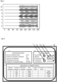
- Fig. 1 describes the emission of sinusoidal acoustic signals as they are picked up by the microphone array, these signals being digitized and recorded in the audio system. Very different amplitudes can be observed although it is the same sound signal emitted by the same sound source, therefore the exploitation of the results is not satisfactory.
- the emission of a sound of a sinusoidal nature is not very pleasant to hear, and we prefer white noise, or pink noise, or simply any noise.
- the document FR3081641 published on November 29, 2019 describes a system for locating sound sources in a 3D environment.
- the sound signals make it possible to establish an acoustic activity map in an N-dimensional sound source localization space, and to project this map onto an axis so as to limit the dimensions and simplify the calculations.
- the present invention therefore aims, by avoiding these drawbacks, to provide a method for determining the direction of a sound source, by using a noise that is more pleasant to hear than a sound of a sinusoidal nature, and by improving the precision of the data defining the direction of the sources.
- the sound emitted by the sound sources has no constraints and can be made more pleasant to a listener than a sinusoidal sound as advocated by known DOA methods. Furthermore, the creation of sinusoidal and phase-shifted signals based on relative arrival times and their use as input parameters, allows to use these DOA methods efficiently.
- the direction value comprises an azimuth datum and an elevation datum. In this way the position of the acoustic enclosure is determined precisely relative to the position of the microphone array.
- the calculation step for determining the azimuth data uses as input sinusoidal signals of a first frequency only and the calculation for determining the elevation data uses as input sinusoidal signals of a second frequency.
- the creation of the two sinusoidal functions is adapted to the calculation of the azimuth and the elevation.
- the first frequency is taken in the interval between 3000 Hz and 3800 Hz, and in that the second frequency is taken in the interval between 6000 Hz and 6800 Hz. In this way, the accuracy of the calculation of the azimuth and the elevation is improved.
- the step of performing cross-correlations between the signals received from the microphones comprises a first step of cross-correlation over the entire duration of the recording to deduce therefrom a maximum correlation value and a second step of cross-correlation around the maximum correlation value using oversampled data obtained from the recording of the sound signals. In this way, the accuracy of the direction values is further improved.
- the calculation step of determining a direction value comprises the Bartlett method. In this manner, the method uses a proven method for calculating azimuth and elevation values.
- the method comprises a polynomial interpolation step performed after the cross-correlation steps and consisting of applying a second-order polynomial to the data resulting from the cross-correlation step of the sound samples located before and after the correlation maximum. In this way, the accuracy of the calculation of the azimuth and elevation is improved.
- the method comprises a step of determining the top and bottom, using an additional microphone located outside the plane in which the other microphones are located. In this way, it is possible to put a sign for the elevation values.
- the sound emitted by the at least one sound source is a white or pink noise. In this way, this sound is little sensitive to disturbances of the environment and is more pleasant to hear.
- the threshold value is different for the azimuth evaluation and for the elevation evaluation.
- the method further comprises a step of displaying a target direction value of at least one sound source with an indication specifying that the value is fixed by the user.
- an installer preferably a professional, can free himself from the recommendations specified by the audio standard and which apply to certain loudspeakers and can decide himself to place them definitively in determined locations.
- the method comprises a step of displaying an indication representative of the correspondence between the determined positions of the sound sources and the theoretical positions associated with the selected audio standard.
- the method comprises a step of determining the format of the audio content, said format defining positions of sound sources, and a step of modifying the parameters transmitted to the audio processor in order to create virtual sound sources using the positions of the sound sources using the method which is the subject of any one of the preceding claims.
- the audio system adapts dynamically according to each reproduced audio content, by creating phantom sources which correspond to the format of the reproduced content.
- the invention relates to a method for configuring an audio system comprising a step of determining the positions of sound sources using the method described above, and a step of comparing all the positions of the sound sources with lists of positions associated with standard configurations, the standard configuration whose positions are closest being then selected and used to configure the audio system.
- the audio system provides significant assistance to the installer for its configuration.
- the invention relates to an audio system for determining a direction comprising at least one sound source and a network of microphones capturing the sound emitted by this sound source, a means of emission by the at least one sound source of a sound, a means of recording the sound signals received by the microphones, means for performing cross-correlations between the received signals in order to deduce relative arrival times therefrom, means for creating, for each microphone, a sinusoidal time signal having a determined frequency and a phase shift dependent on the relative arrival times, and means for determining a direction value of the sound source according to a spatial reference defined by the microphone array using the sinusoidal time signals as an input parameter, said direction value thus determined being presented on a support.
- the invention relates to a method for determining a direction of a sound source using an audio system that captures the sound emitted by the sound source by a microphone array.
- the method comprises the following steps: emitting a sound by the sound source and recording the sound signals received by the microphone array, performing cross-correlations between the received signals in order to deduce relative arrival times therefrom, creating, for each microphone, a sinusoidal time signal having a determined frequency and a phase shift dependent on the relative arrival times, calculating the determination of a value of direction of the sound source according to a spatial reference defined by the microphone array using as input parameter the sinusoidal signals of time, presentation of the direction value.
- FIG. 2 describes an exemplary embodiment of an audio system for determining the direction of at least one sound source.
- This system has an audio amplifier 1 connected to a display device 2 such as a display screen or a video projector.
- the screen is intended in particular to display configuration menus and speaker direction values in a 3D space.
- the audio amplifier 1 is provided with a central unit 3 connected in particular to a memory 4 containing executable programs, an infrared signal reception interface 5 for receiving signals from a keyboard or a remote control 6, a video interface 7 for creating visual signals sent to the display device 2.
- the video interface 7 has a text and graphics generation circuit for displaying text, graphics, pictograms on the screen, whether or not superimposed on visual content.
- the video interface 7 is controlled by the central unit 3 in association with an executable program stored in the memory 4.
- the audio amplifier 1 is equipped with an interface 8 for communication with a remote server via a digital network 9. This connection makes it possible to receive audio or audiovisual content for reproduction purposes, and configuration data for receiving audio standard parameters for example.
- the communication can be carried out over short or long range, for example with a wireless local area network (Wifi or Bluetooth).
- the remote control or keyboard 6 transmits signals to the interface 5 to control the operation of the audio amplifier 1, the volume for example.
- the audio amplifier 1 is also provided with a data memory 10 for storing configuration data and possibly audio content.
- the audio amplifier 1 comprises an audio interface 11 for amplifying analog signals to a plurality of loudspeakers 12.
- the loudspeakers are powered by the mains and the amplifier 1 delivers a low-power signal.
- the connection with the loudspeakers, wired or by radio is of the digital type, the loudspeakers decoding a digital data stream to provide an analog signal to the loudspeakers.
- the audio amplifier 1 comprises an interface circuit 13 with a network of microphones 14 intended to capture the ambient sound, and in particular the acoustic signals emitted by the speakers 12.
- the program memory 4 comprises software for determining the direction of the acoustic speakers 12 according to the acoustic signals captured by the network of microphones 14.
- the network of microphones is connected to a computer itself in communication with the amplifier 1. In this case, the network of microphones is connected to an electronic card inserted in the computer of the PC type for example, this electronic card is provided with inputs whose number is at least equal to that of the microphones of the network 14.
- the computer carries out the acoustic measurements by controlling the amplifier 1, calculates the directions of the acoustic speakers 12 and transmits any corrections to be applied to the sound signals.
- Fig. 3 illustrates a representation of a microphone array 14 for capturing the sound emitted by at least one sound source, according to a preferred embodiment.
- the array has at least four microphones arranged for example at the vertices of a regular tetrahedron, which constitutes the most economical solution.
- Other arrangements are possible such as that described by the Fig. 3 consisting of a crown of 6 microphones distributed at regular intervals on the circumference of a circle, a seventh is placed in the center of this circle and an eighth is placed at a height vertical to the seventh.
- the radius of the circle is 97 millimeters.
- This eighth microphone does not participate in the actual direction calculations but makes it possible to detect the top and bottom of the network 14 and thus to put a sign in the elevation value associated with each acoustic enclosure.
- Another arrangement consists of using six microphones distributed regularly on the circumference of a circle, a seventh placed high on the vertical line starting from the center of the circle. Microphones are preferably omnidirectional with a 3 db bandwidth from 100 Hz to 10 KHz.
- the example of realization with 6 microphones produced the best results due to its central symmetry around a vertical axis comprising the seventh and eighth microphones.
- the experiment was carried out by positioning the microphone network 14 at 4 meters from the nearest acoustic speakers 12, but this value is only indicative, it is obvious that by having a larger room, this distance increases.
- the more microphones there are arranged on the circle the more the system records small deviations and is less sensitive to noise.
- FIG. 4 describes a flowchart of a method for determining the direction of at least one sound source, according to an exemplary embodiment.
- the invention is situated, for example, in the context of an acoustic installation comprising an amplifier and a plurality of loudspeakers, possibly coupled to a screen or a video projector so as to create a real home cinema.
- an installer positions the loudspeakers in positions as recommended by the manufacturer of the acoustic installation. Let's take a very simple example of an installation with five loudspeakers, the positions are indicated for example as follows: Speaker ID Manufacturer's recommended instructions Center front 4 meters away, facing the listeners Front left 30° left forward, 4.5 m from the listeners Right front 30° right forward, 4.5 m from the listeners Left back top 45° left behind, 4.5 m from the listeners Right back top 45° right behind, 4.5 m from the listeners
- step 4.1 amplifier 1 generates a non-sinusoidal sound to a first loudspeaker.
- sinusoidal signals are good input parameters for estimating directions using methods such as Bartlett's, reflections and absorptions due to The environment distorts acoustic signals considerably but has little effect involving large differences on the wave received directly by the microphone array.
- Experimentation and theory have shown that a sound of non-sinusoidal nature has a good signal-to-noise ratio and produces good results that are independent of the environment. Correlation curves applied to pairs of microphones show a clear peak with this type of signal, which allows a better separation of the source and the parasites. It is also more comfortable for listeners to hear pink or white noise than a pure sinusoidal signal.
- the amplifier 1 is equipped with a pink noise generator.
- pink noise is a random signal whose spectral density is constant per octave band and that its power spectral density is inversely proportional to the frequency of the signal.
- One of the natural sounds that most closely resembles pink noise is that of a torrent or a waterfall, produced by random frequencies added to the impact of more or less significant masses of water on rocks. Such a noise is therefore quite pleasant to hear.
- the noise emitted by this first acoustic enclosure is captured by the microphone array, and recorded in the form of sequences of sound samples (step 4.2). More precisely, the analog signals transmitted by the microphones are digitized by an A/D converter and the data thus produced are recorded in the memory 10.
- Cross-correlation is a calculation used to determine a value proportional to the degree of correlation of two signals. It consists of a convolution performed between two signals giving a third signal resulting from the correlation between the two. This third signal has a value that increases, reaches a maximum and decreases when two identical signals are at the input.
- Cross-correlation is inspired by the method described by Peter D. Welch, but this method is given as an example only. Experimentation has determined that a signal length of 32768 samples and an overlap of 75% are sufficient to stabilize the results.
- a first pass is performed on the signals in order to determine the maximum in the correlation value curve, between the data coming from a pair of microphones, the maximum of this curve allowing to calculate the relative arrival times of the same acoustic signal captured by a pair of microphones.
- This first pass is fast because it is performed on a small amount of data but produces an imprecise result. It is then necessary to refine the values around the correlation maximum.
- an oversampling step is applied to the recorded data in order to produce more precise data by interpolation. Experimentation has shown that oversampling by sixteen times to reach 768 KHz provides good results while not using too much power and computing time. Oversampling begins by inserting fifteen locations between each sample, and initializing them to "0".
- a low-pass filter with a cutoff frequency of about 20 kHz is applied to the data to reconstruct the signal and fill the locations with significant values.
- a 1056-coefficient FIR filter is used to perform this oversampling.
- a second cross-correlation step is then applied to the data obtained by oversampling (step 4.5) in order to determine a value proportional to the degree of correlation between two sample packets. Applying two cross-correlation steps saves time, as the first provides coarse results that are refined by the second.
- step 4.6 a polynomial interpolation is applied to the cross-correlation values to obtain a better estimate of the relative arrival times.
- a second-order polynomial is applied to the data resulting from the cross-correlation step of the samples located before and after the maximum. In this way, the cross-correlations allow to estimate a more precise inter-sample arrival time.
- A is the unitless amplitude
- P the pulsation of the quantity in radians per second
- t the time in seconds
- ph the phase at the origin (in radians).
- the sinusoidal curves are constructed with delays corresponding to the estimated TOAs and are then used as an input parameter for an estimation of the DOA according to the Bartlett method.
- Each of these curves is a theoretical modeling of the sound emitted by the sound source whose position is to be calculated and received by a microphone while passing through an environment without reverberation or absorption.
- the sinusoidal curves thus created are phase-shifted relative to each other according to the relative arrival times TOA.
- two curves are calculated and associated with each microphone, one with a first frequency is intended to calculate the azimuth, and the other with a second frequency is intended to calculate the elevation accurately.
- the experiment gave good results using a first frequency of 3400 Hz (+/- 5%) and a second frequency of 6400 Hz (+/- 5%).
- the determination of the frequencies is obtained by mathematical modeling of the system considered.
- the sound signals theoretically captured by the microphones as well as the theoretical position of the sources are known.
- the frequency thus determined depends mainly on the geometry of the microphone array, the modeling then being simpler at the level of the propagation of the acoustic waves (which radiate around the source) and the influence of the environment (we only take into account the reverberation).
- the speed of sound is taken into account for better accuracy of the calculated data.
- DOA methods depend on the speed of sound. Since they use it in an exponential to describe the phase decay between microphones, a small error in the speed of sound can lead to a bad estimation of the position. This is why the software asks the installer to indicate the ambient temperature.
- An equation calculating the speed of sound as a function of the ambient temperature is used to adjust the direction vectors. In a refinement that was not implemented in the prototype, the equation for calculating the speed of sound takes into account not only the temperature, but also the humidity and the atmospheric pressure.
- step 4.8 Bartlett's method is applied using the characteristics of the two sinusoidal curves created in the previous step.
- This method for calculating DOAs is well known, particularly through works such as the HAL document “Comparative Study between Several Directions of Arrival, Estimation Method”, by Youssef KHMO, Sa ⁇ d Safi, Miloud FRIKEL . This method therefore does not need to be explained further in this document.
- the azimuth value is first calculated using all possible pairs of microphones located on the same plane. Using the microphone array as described by the Fig. 3 , seven microphones allow to create twenty-one possible pairs. The large number of microphones on the periphery allows to obtain a good precision for the azimuth value, of the order of 2°.
- each signal picked up by a microphone is compared by a cross-correlation with that of another microphone, thus each comparison generates a relative delay which can be reduced without great complexity to a delay relative to the central microphone, the seventh according to the embodiment described by the Fig. 2 .
- All cross-correlation results are relativized to the central microphone and averaged. In this way, all signals are combined together in every possible way, producing delays relative to each microphone, these delays are brought back to be relative to the central microphone using the relative delays calculated with this central microphone. The last operation is to average the calculated values which are all relative to the central microphone, and thus obtain the best possible precision.
- the eighth microphone is used (according to the embodiment described by the Fig. 2 ) which is placed vertically above the plane containing the first microphones, at a height above said plane preferably equal to the radius.
- This microphone does not allow to calculate a better Bartlett direction vector because it breaks the central symmetry. However, it creates a right triangle with the seventh microphone and a radius of the circle, which is sufficient to calculate an elevation. Determining the top and bottom allows in particular to add a sign to the elevation value.
- step 4.10 the method tests whether there are other loudspeakers 12 whose position is to be determined. If this is the case, then the method loops back to step 4.1 and reprograms the amplifier 1 to generate the same noise towards another loudspeaker. The loop thus generated makes it possible to sequentially record a set of sequences of sound samples associated with each loudspeaker and intended to calculate its position. When all the loudspeakers have produced a sound, the step of analyzing the recorded data can begin. In this way, the sound is emitted successively by each loudspeaker in a time block and is more pleasant to hear.
- all of the acoustic signals are emitted by the different sources without analyzing their directions, all of the signals are thus recorded and then the data analysis takes place to determine all of the directions of the sound sources.
- the signals are analyzed, and in parallel, another set of acoustic signals emitted by another source is recorded.
- step 4.11 the azimuth and elevation values just determined are compared with target values, specific to the audio standard selected by the installer.
- the selected audio standard defines the direction (in terms of azimuth and elevation) of each sound source relative to where a listener is expected to be.
- each loudspeaker is in the right place or whether he must move it.
- the installer selects a reproduction standard at the user interface level; this standard must specify the same number of loudspeakers as that detected by the audio system.
- Each loudspeaker is referenced by an identifier, which is associated with azimuth and elevation values specified by this audio standard.
- Speaker ID Measured values Standard values Center front (2°, 0°) (0.0) Front left (22°,0°) (30°,0°) Right front (-25°,0°) (-30°,0°) Left back top (122° ,0° ) (135° ,0° ) Right back top (-120°,0°) (-135°,0°)
- the values of the standard are specified by standardization committees in the field of audio systems.
- the method comprises a step of selecting one standard from several.
- the method proposes a standard recommended by the manufacturer of the audio system implementing the invention.
- the method develops a correction strategy to compensate for the positioning defects of the sound sources.
- a first strategy is to create "phantom" sources. To do this, two or three loudspeakers are used to create a phantom source that a listener locates by auditory perception at a location where a single loudspeaker should be located. This illusion is created by broadcasting coherent signals, with a specific gain, on two or three loudspeakers. This principle is identical to that of a stereo panoramic signal but extended to 3D space. As a result, a signal intended for a single loudspeaker is in fact transmitted with different weightings to two or three loudspeakers located around a target position defined according to the audio standard.
- a second strategy is to issue recommendations to the installer to physically move the loudspeaker.
- Step 4.12 describes the choice between one or the other strategy depending on the deviations between the calculated and retrieved direction values. If the deviation is above a determined threshold value, the method issues the recommendation to move the acoustic enclosure. When the deviation is below a threshold value, the amplifier can modify the sound emitted towards one or more enclosures located approximately in this direction to give the impression to the listener that the sound comes from the target position.
- the thresholds for the azimuth and for the elevation are different. For example, if the deviation between the calculated azimuth value and that of the standard exceeds 10° then a displacement of the enclosure is recommended. Similarly, if the deviation between the calculated elevation value and that of the standard exceeds 15° then a displacement of the enclosure is recommended. A displacement of the enclosure is recommended if one and/or the other of the deviations exceeds the corresponding threshold.
- Fig. 5 represents an example of a menu displayed on screen 2 allowing the installer to analyze for the first time the direction of the acoustic speakers 12, to receive recommendations to improve listening comfort and thus be as close as possible to an audio standard and to configure his audio system for reproduction purposes.
- the audio system automatically determines the name and/or characteristics of the audio standard and then configures the audio system with the discovered elements. This determination consists of a step of detecting the position of each sound source according to the method which is the subject of the invention and in a step of comparing all the positions with lists of parameters associated with standard configurations, of the type for example X1.X2.X3.X4, where: X1 is the number of sources in the low layer (at ear level), X2 is the number of sources dedicated to low frequencies, X3 is the number of sources fixed to the walls of the room, and X4 is the number of sources fixed to the ceiling.
- the audio system has a library of sets of parameters each associated with an audio standard.
- the detection step provides the directions and the numbers of sources positioned according to each parameter X1, X2, X3 and X4, these directions and numbers are then compared with those of the audio standards recorded in the library and the standard whose numbers are the closest is then selected and displayed on the screen in the 5.1 configuration window.
- Other comparison elements can be taken into account to determine the closest standard, such as the bandwidth of the sources, or the distance from the microphone network.
- An icon displayed in the immediate vicinity of the identifier of the detected standard allows the user to validate the choice proposed by the audio system, the latter then configures the different audio streams according to the standard validated by the user. In this way, the configuration made by the user is simplified and the risks of introducing an erroneous standard are limited.
- the control and status window 5.2 typically displays an icon 5.4 for launching the determination of the position of each acoustic enclosure.
- a graphic line 5.5 presents a cursor moving on the line indicating the progress level of the position determination step, a window 5.6 displays the identifier of the enclosure currently being calculated.
- An icon 5.7 is used to launch the execution of the emission of recommendations following a measurement phase, a second graphic line 5.8 presents the progress of the recommendation calculation.
- the type of correction to be made is either to create a "phantom source” by modifying the signals of the speakers close to this direction (by displaying "Num”), in this way the listener's hearing perceives a source coming from a place where a speaker should be, or to ask the installer to move the speaker because the difference is too great to compensate (by displaying "Move”).
- this menu can be displayed on a secondary screen 2, its content is then produced by the amplifier 1.
- the menu can also be that of a laptop computer, in communication with the amplifier 1 and capable of receiving and analyzing the sound signals received from the microphone array 14.
- the menu appearing on the screen when configuring its audio system displays a similarity score representative of the correspondence between the positions of the sound sources detected by the method that is the subject of the invention and the theoretical configuration associated with the audio standard identified in window 5.1.
- This similarity score makes it possible to indicate to the user to what extent the overall positioning of the sources is close to that recommended by the audio standard.
- the score can be displayed in the form of a rating, varying from 0 to 10, 10 being the value for which the sources are installed in the correct position.
- the score can also be displayed as a color code, with red indicating poor positioning, orange indicating improvement that could be improved, and green indicating good positioning. Alternatively, this color code can be applied to each sound source and is displayed individually for each row of the table appearing in window 5.3.
- the line associated with source number 1 whose recommendation is a move appears in red.
- the user can easily visualize the score corresponding to his installation and worked iteratively on its improvement.
- a maximum score thus ensures the best level of sound fidelity relative to a choice of audio standard.
- Other icons are possible to introduce other commands, such as removing a speaker, or adding one, introducing the degree of humidity, atmospheric pressure, ...
- the user can decide to freeze the position (azimuth and elevation) of one or more sound sources and thus no longer take into account the positions specified by the audio standard which is identified in the 5.1 window appearing in the Fig. 5 .
- This improvement allows the user to introduce his own corrections without taking into account those resulting from the stream decoded by the audio processor. In this way, a professional installer can free himself from the recommendations specified by the audio standard for certain loudspeakers and decide himself to place them in specific locations. The user deciding to deviate from the audio standard, the similarity score therefore no longer has any meaning and is no longer displayed.
- the target azimuth and target elevation values that appear in the table in window 5.3 and which correspond to positions fixed by the user are displayed with a graphic characteristic such as: underlining, flashing or a particular color.
- the audio system when reproducing audio content, the audio system adapts its audio processor (or "codec") according to the format of the audio document and the position of the sound sources detected by the method as described above.
- a codec is a hardware or software device for implementing the encoding or decoding of a digital data stream, with a view to reproduction or storage.
- the format of the audio content to be reproduced specifies the position of the sound sources.
- the audio system creates phantom sources so that they are virtually located at the positions defined by the format, and modifies the parameters sent to the codec according to the actual position of the speakers.
- This step of reprogramming the audio processor in order to create phantom sources is carried out each time sound content is reproduced, a specific display may then appear indicating, for example, the number of phantom sources.
Landscapes
- Engineering & Computer Science (AREA)
- Physics & Mathematics (AREA)
- Signal Processing (AREA)
- Acoustics & Sound (AREA)
- Otolaryngology (AREA)
- General Health & Medical Sciences (AREA)
- Health & Medical Sciences (AREA)
- Quality & Reliability (AREA)
- Electromagnetism (AREA)
- Computer Networks & Wireless Communication (AREA)
- General Physics & Mathematics (AREA)
- Radar, Positioning & Navigation (AREA)
- Remote Sensing (AREA)
- Measurement Of Velocity Or Position Using Acoustic Or Ultrasonic Waves (AREA)
- Circuit For Audible Band Transducer (AREA)
Claims (16)
- Verfahren zur Bestimmung einer Richtung mindestens einer Schallquelle (12) mit Hilfe eines Audiosystems, das durch ein Netzwerk aus Mikrofonen (14) den Ton aufnimmt, der von mindestens einer Schallquelle abgegeben wird, das die folgenden Schritte umfasst:- Abgabe (4.1) durch mindestens eine Schallquelle eines Tons und Aufzeichnen der Tonsignale, die von den Mikrofonen empfangen werden,- Ausführung (4.3, 4.5) von Kreuzkorrelationen zwischen empfangenen Signalen, um daraus die relativen Ankunftszeiten abzuleiten, wobei das Verfahren außerdem die folgenden Schritte umfasst:- Anlegung (4.7) für jedes Mikrofon (14) eines Sinussignals der Zeit, das eine bestimmte Frequenz und eine Phasenverschiebung während relativer Ankunftszeiten aufweist,- Bestimmungsberechnung (4.8) eines Richtungswerts der Schallquelle gemäß einem räumlichen Anhaltspunkt, der von dem Netzwerk aus Mikrofonen definiert ist, unter Verwendung der Sinussignale der Zeit als Eingangsparameter,- Präsentation des Richtungswerts.
- Verfahren zur Bestimmung einer Richtung nach Anspruch 1, wobei der Richtungswert ein Azimutdatum und ein Elevationsdatum umfasst.
- Verfahren zur Bestimmung einer Richtung nach Anspruch 2, wobei der Schritt (4.8) der Bestimmungsberechnung des Azimutdatums am Eingang nur Sinussignale mit einer ersten Frequenz verwendet, und der Bestimmungsberechnung des Elevationsdatums am Eingang der Sinussignale mit einer zweiten Frequenz verwendet.
- Verfahren zur Bestimmung einer Richtung nach Anspruch 3, wobei die erste Frequenz in dem Intervall zwischen 3000 Hz und 3800 Hz genommen wird, und die zweite Frequenz in dem Intervall zwischen 6000 Hz und 6800 Hz genommen wird.
- Verfahren zur Bestimmung einer Richtung nach einem der vorstehenden Ansprüche, wobei der Ausführungsschritt von Kreuzkorrelationen zwischen den von den Mikrofonen empfangenen Signalen einen ersten Schritt (4.3) zur Kreuzkorrelation auf der gesamten Dauer der Aufzeichnung umfasst, um daraus einen Korrelationshöchstwert abzuleiten, und einen zweiten Kreuzkorrelationsschritt (4.5) um den Korrelationshöchstwert unter Verwendung überabgetasteter Daten, die ausgehend von der Aufzeichnung der Tonsignale erhalten werden.
- Verfahren zur Bestimmung einer Richtung nach einem der vorstehenden Ansprüche, wobei der Schritt (4.8) der Bestimmungsberechnung eines Richtungswerts das Bartlettsche Verfahren umfasst.
- Verfahren zur Bestimmung einer Richtung nach einem der vorstehenden Ansprüche, das einen polynominalen Interpolationsschritt umfasst, der nach den Kreuzkorrelationsschritten (4.3, 4.5) ausgeführt wird und darin besteht, ein Polynom zweiter Ordnung an die Daten anzuwenden, die sich aus dem Kreuzkorrelationsschritt der Tonabtastwerte, die vor und nach dem Korrelationsmaximum liegen, ergeben.
- Verfahren zur Bestimmung einer Richtung nach einem der vorstehenden Ansprüche, das einen Bestimmungsschritt (4.9) von oben und von unten unter Verwendung eines zusätzlichen Mikrofons umfasst, das sich außerhalb der Ebene befindet, in der die anderen Mikrofone befinden.
- Verfahren zur Bestimmung einer Richtung nach einem der vorstehenden Ansprüche, wobei der abgegebene Ton von mindestens einer Schallquelle ein weißes oder rosa Rauschen ist.
- Verfahren zur Bestimmung einer Richtung nach einem der vorstehenden Ansprüche, das die folgenden zusätzlichen Schritte umfasst:- Auswahl eines Audiostandards, der die Richtung mindestens einer Schallquelle in Bezug auf den Ort, an dem sich ein Zuhörer befinden soll, definiert,- Gewinnung der Zielpositionen jeder Schallquelle, die dem ausgewählten Audiostandard zugeordnet sind,- Berechnung des Abstands zwischen den berechneten Richtungswerten und den gewonnenen Werten und Vergleich des Abstands zwischen den Werten mit einem Schwellenwert,- Auswahl (4.12) einer Strategie gemäß der der Wert des Abstands kleiner oder größer als der Schwellenwert ist, wobei die Strategie darauf abzielt, den Abstand zwischen der gewonnenen Richtung und der von einem Zuhörer, der an dem Ort des Netzwerks aus Mikrofonen platziert ist, empfundenen Richtung zu reduzieren.
- Verfahren zur Bestimmung einer Richtung nach Anspruch 10, wobei der Schwellenwert zur Azimutbewertung und zur Elevationsbewertung unterschiedlich ist.
- Verfahren zur Bestimmung einer Richtung nach einem der Ansprüche 10 und 11, das einen Anzeigeschritt eines Zielrichtungswerts mindestens einer Schallquelle mit einer Angabe umfasst, die spezifiziert, dass der Wert durch die Einführung eines Befehls eingefroren wird.
- Verfahren zur Bestimmung einer Richtung nach einem der Ansprüche 10 und 12, das einen Anzeigeschritt einer Angabe umfasst, die für die Entsprechung zwischen den bestimmten Positionen der Schallquellen und den theoretischen Positionen, die dem ausgewählten Audiostandard zugeordnet sind, repräsentativ ist.
- Verfahren zur Wiedergabe eines Audioinhalts, das einen Bestimmungsschritt des Formats des Audioinhalts während der Wiedergabe umfasst, wobei das Format Schallquellenpositionen definiert, und einen Änderungsschritt der Parameter, die an den Audioprozessor übertragen werden, um virtuelle Schallquellen unter Verwendung der Positionen der Schallquellen unter Verwendung des Verfahrens, das Gegenstand eines der vorstehenden Ansprüche ist, zu schaffen.
- Verfahren zur Konfiguration eines Audiosystems, das einen Bestimmungsschritt der Positionen von Schallquellen unter Verwendung des Verfahrens, das Gegenstand eines der Ansprüche 1 bis 12 ist, und einen Vergleichsschritt sämtlicher Positionen der Schallquellen mit Positionslisten, die Standardkonfigurationen zugeordnet sind, umfasst, wobei die Standardkonfiguration, deren Positionen die nächstliegenden sind, ausgewählt und zum Konfigurieren des Audiosystems verwendet werden.
- Audiosystem zur Bestimmung einer Richtung, das mindestens eine Schallquelle (12) und ein Netzwerk aus Mikrofonen (14), die den von dieser Schallquelle abgegebenen Ton aufnehmen, umfasst, das ein Sendemittel (11) durch die mindestens eine Schallquelle eines Tons, ein Aufzeichnungsmittel (10) der von den Mikrofonen empfangenen Tonsignale, ein Ausführungsmittel (3, 4) von Kreuzkorrelationen zwischen den empfangenen Signalen zur Ableitung daraus der relativen Ankunftszeiten umfasst, wobei das System außerdem die folgenden Mittel umfasst: ein Mittel zum Erzeugen (3, 4) für jedes Mikrofon (14) eines Sinussignals der Zeit, das eine bestimmte Frequenz und eine Phasenverschiebung in Abhängigkeit von den relativen Ankunftszeiten aufweist, und ein Bestimmungsmittel (3, 4) eines Richtungswerts der Schallquelle gemäß einem räumlichen Anhaltspunkt, der von dem Netzwerk aus Mikrofonen (14) unter Verwendung als Eingangsparameter der Sinussignale der Zeit definiert wird, wobei der derart bestimmte Richtungswert auf einem Träger (2) präsentiert wird.
Applications Claiming Priority (2)
| Application Number | Priority Date | Filing Date | Title |
|---|---|---|---|
| FR2102105A FR3120449B1 (fr) | 2021-03-04 | 2021-03-04 | Procédé de détermination d’une direction de propagation d’une source sonore par création de signaux sinusoïdaux à partir des signaux sonores reçus par des microphones. |
| PCT/EP2022/055329 WO2022184800A1 (fr) | 2021-03-04 | 2022-03-02 | Procédé de détermination d'une direction de propagation d'une source sonore par création de signaux sinusoïdaux à partir des signaux sonores reçus par des microphones |
Publications (3)
| Publication Number | Publication Date |
|---|---|
| EP4302114A1 EP4302114A1 (de) | 2024-01-10 |
| EP4302114C0 EP4302114C0 (de) | 2025-02-19 |
| EP4302114B1 true EP4302114B1 (de) | 2025-02-19 |
Family
ID=76034732
Family Applications (1)
| Application Number | Title | Priority Date | Filing Date |
|---|---|---|---|
| EP22714117.3A Active EP4302114B1 (de) | 2021-03-04 | 2022-03-02 | Verfahren zur bestimmung einer ausbreitungsrichtung einer schallquelle durch erzeugung sinusförmiger signale aus von mikrofonen empfangenen tonsignalen |
Country Status (4)
| Country | Link |
|---|---|
| US (1) | US12407985B2 (de) |
| EP (1) | EP4302114B1 (de) |
| FR (1) | FR3120449B1 (de) |
| WO (1) | WO2022184800A1 (de) |
Families Citing this family (3)
| Publication number | Priority date | Publication date | Assignee | Title |
|---|---|---|---|---|
| US12170097B2 (en) * | 2022-08-17 | 2024-12-17 | Caterpillar Inc. | Detection of audio communication signals present in a high noise environment |
| US20250056145A1 (en) * | 2023-08-08 | 2025-02-13 | Cisco Technology, Inc. | Detecting active speakers using head detection |
| CN121027996B (zh) * | 2025-10-30 | 2026-02-24 | 华东交通大学 | 一种利用时间延迟以及航位推测的声源定位方法 |
Family Cites Families (5)
| Publication number | Priority date | Publication date | Assignee | Title |
|---|---|---|---|---|
| US6912178B2 (en) * | 2002-04-15 | 2005-06-28 | Polycom, Inc. | System and method for computing a location of an acoustic source |
| JP2008154130A (ja) * | 2006-12-20 | 2008-07-03 | Matsushita Electric Ind Co Ltd | 音場測定装置 |
| US9426598B2 (en) * | 2013-07-15 | 2016-08-23 | Dts, Inc. | Spatial calibration of surround sound systems including listener position estimation |
| US9578439B2 (en) * | 2015-01-02 | 2017-02-21 | Qualcomm Incorporated | Method, system and article of manufacture for processing spatial audio |
| FR3081641A1 (fr) | 2018-06-13 | 2019-11-29 | Orange | Localisation de sources sonores dans un environnement acoustique donne. |
-
2021
- 2021-03-04 FR FR2102105A patent/FR3120449B1/fr not_active Expired - Fee Related
-
2022
- 2022-03-02 EP EP22714117.3A patent/EP4302114B1/de active Active
- 2022-03-02 WO PCT/EP2022/055329 patent/WO2022184800A1/fr not_active Ceased
- 2022-03-02 US US18/548,408 patent/US12407985B2/en active Active
Also Published As
| Publication number | Publication date |
|---|---|
| FR3120449A1 (fr) | 2022-09-09 |
| EP4302114A1 (de) | 2024-01-10 |
| US20240236573A9 (en) | 2024-07-11 |
| WO2022184800A1 (fr) | 2022-09-09 |
| EP4302114C0 (de) | 2025-02-19 |
| US20240137702A1 (en) | 2024-04-25 |
| FR3120449B1 (fr) | 2023-10-27 |
| US12407985B2 (en) | 2025-09-02 |
Similar Documents
| Publication | Publication Date | Title |
|---|---|---|
| EP4302114B1 (de) | Verfahren zur bestimmung einer ausbreitungsrichtung einer schallquelle durch erzeugung sinusförmiger signale aus von mikrofonen empfangenen tonsignalen | |
| US11528576B2 (en) | Distributed audio capturing techniques for virtual reality (VR), augmented reality (AR), and mixed reality (MR) systems | |
| EP3262853B1 (de) | Computerprogramm und verfahren zur bestimmung einer personalisierten kopfbezogenen übertragungsfunktion und interaurale zeitdifferenzfunktion | |
| EP0790753B1 (de) | System für Raumklangeffekt und Verfahren dafür | |
| US9729993B2 (en) | Apparatus and method for reproducing recorded audio with correct spatial directionality | |
| EP1479266B1 (de) | Verfahren und vorrichtung zur steuerung einer anordnung zur wiedergabe eines schallfeldes | |
| EP1586220B1 (de) | Verfahren und einrichtung zur steuerung einer wiedergabeeinheitdurch verwendung eines mehrkanalsignals | |
| US20150215723A1 (en) | Wireless speaker system with distributed low (bass) frequency | |
| US10791412B2 (en) | Particle-based spatial audio visualization | |
| EP4080910B1 (de) | System und verfahren zur erzeugung von impulsantworten | |
| WO2011095422A1 (fr) | Methode pour creer un environnement audio avec n haut-parleurs | |
| US20230362568A1 (en) | Apparatus, Methods and Computer Programs for Adapting Audio Processing |
Legal Events
| Date | Code | Title | Description |
|---|---|---|---|
| STAA | Information on the status of an ep patent application or granted ep patent |
Free format text: STATUS: UNKNOWN |
|
| STAA | Information on the status of an ep patent application or granted ep patent |
Free format text: STATUS: THE INTERNATIONAL PUBLICATION HAS BEEN MADE |
|
| PUAI | Public reference made under article 153(3) epc to a published international application that has entered the european phase |
Free format text: ORIGINAL CODE: 0009012 |
|
| STAA | Information on the status of an ep patent application or granted ep patent |
Free format text: STATUS: REQUEST FOR EXAMINATION WAS MADE |
|
| 17P | Request for examination filed |
Effective date: 20230831 |
|
| AK | Designated contracting states |
Kind code of ref document: A1 Designated state(s): AL AT BE BG CH CY CZ DE DK EE ES FI FR GB GR HR HU IE IS IT LI LT LU LV MC MK MT NL NO PL PT RO RS SE SI SK SM TR |
|
| DAV | Request for validation of the european patent (deleted) | ||
| DAX | Request for extension of the european patent (deleted) | ||
| GRAP | Despatch of communication of intention to grant a patent |
Free format text: ORIGINAL CODE: EPIDOSNIGR1 |
|
| STAA | Information on the status of an ep patent application or granted ep patent |
Free format text: STATUS: GRANT OF PATENT IS INTENDED |
|
| GRAS | Grant fee paid |
Free format text: ORIGINAL CODE: EPIDOSNIGR3 |
|
| INTG | Intention to grant announced |
Effective date: 20241112 |
|
| GRAA | (expected) grant |
Free format text: ORIGINAL CODE: 0009210 |
|
| STAA | Information on the status of an ep patent application or granted ep patent |
Free format text: STATUS: THE PATENT HAS BEEN GRANTED |
|
| AK | Designated contracting states |
Kind code of ref document: B1 Designated state(s): AL AT BE BG CH CY CZ DE DK EE ES FI FR GB GR HR HU IE IS IT LI LT LU LV MC MK MT NL NO PL PT RO RS SE SI SK SM TR |
|
| REG | Reference to a national code |
Ref country code: GB Ref legal event code: FG4D Free format text: NOT ENGLISH |
|
| REG | Reference to a national code |
Ref country code: CH Ref legal event code: EP |
|
| REG | Reference to a national code |
Ref country code: DE Ref legal event code: R096 Ref document number: 602022010844 Country of ref document: DE |
|
| REG | Reference to a national code |
Ref country code: IE Ref legal event code: FG4D Free format text: LANGUAGE OF EP DOCUMENT: FRENCH |
|
| U01 | Request for unitary effect filed |
Effective date: 20250317 |
|
| U07 | Unitary effect registered |
Designated state(s): AT BE BG DE DK EE FI FR IT LT LU LV MT NL PT RO SE SI Effective date: 20250324 |
|
| PGFP | Annual fee paid to national office [announced via postgrant information from national office to epo] |
Ref country code: AT Payment date: 20250417 Year of fee payment: 4 |
|
| U20 | Renewal fee for the european patent with unitary effect paid |
Year of fee payment: 4 Effective date: 20250327 |
|
| PG25 | Lapsed in a contracting state [announced via postgrant information from national office to epo] |
Ref country code: RS Free format text: LAPSE BECAUSE OF FAILURE TO SUBMIT A TRANSLATION OF THE DESCRIPTION OR TO PAY THE FEE WITHIN THE PRESCRIBED TIME-LIMIT Effective date: 20250519 |
|
| PG25 | Lapsed in a contracting state [announced via postgrant information from national office to epo] |
Ref country code: PL Free format text: LAPSE BECAUSE OF FAILURE TO SUBMIT A TRANSLATION OF THE DESCRIPTION OR TO PAY THE FEE WITHIN THE PRESCRIBED TIME-LIMIT Effective date: 20250219 |
|
| PG25 | Lapsed in a contracting state [announced via postgrant information from national office to epo] |
Ref country code: ES Free format text: LAPSE BECAUSE OF FAILURE TO SUBMIT A TRANSLATION OF THE DESCRIPTION OR TO PAY THE FEE WITHIN THE PRESCRIBED TIME-LIMIT Effective date: 20250219 |
|
| PG25 | Lapsed in a contracting state [announced via postgrant information from national office to epo] |
Ref country code: IS Free format text: LAPSE BECAUSE OF FAILURE TO SUBMIT A TRANSLATION OF THE DESCRIPTION OR TO PAY THE FEE WITHIN THE PRESCRIBED TIME-LIMIT Effective date: 20250619 Ref country code: NO Free format text: LAPSE BECAUSE OF FAILURE TO SUBMIT A TRANSLATION OF THE DESCRIPTION OR TO PAY THE FEE WITHIN THE PRESCRIBED TIME-LIMIT Effective date: 20250519 |
|
| PG25 | Lapsed in a contracting state [announced via postgrant information from national office to epo] |
Ref country code: HR Free format text: LAPSE BECAUSE OF FAILURE TO SUBMIT A TRANSLATION OF THE DESCRIPTION OR TO PAY THE FEE WITHIN THE PRESCRIBED TIME-LIMIT Effective date: 20250219 |
|
| PG25 | Lapsed in a contracting state [announced via postgrant information from national office to epo] |
Ref country code: GR Free format text: LAPSE BECAUSE OF FAILURE TO SUBMIT A TRANSLATION OF THE DESCRIPTION OR TO PAY THE FEE WITHIN THE PRESCRIBED TIME-LIMIT Effective date: 20250520 |
|
| PG25 | Lapsed in a contracting state [announced via postgrant information from national office to epo] |
Ref country code: SM Free format text: LAPSE BECAUSE OF FAILURE TO SUBMIT A TRANSLATION OF THE DESCRIPTION OR TO PAY THE FEE WITHIN THE PRESCRIBED TIME-LIMIT Effective date: 20250219 |
|
| PG25 | Lapsed in a contracting state [announced via postgrant information from national office to epo] |
Ref country code: CZ Free format text: LAPSE BECAUSE OF FAILURE TO SUBMIT A TRANSLATION OF THE DESCRIPTION OR TO PAY THE FEE WITHIN THE PRESCRIBED TIME-LIMIT Effective date: 20250219 |
|
| REG | Reference to a national code |
Ref country code: CH Ref legal event code: H13 Free format text: ST27 STATUS EVENT CODE: U-0-0-H10-H13 (AS PROVIDED BY THE NATIONAL OFFICE) Effective date: 20251023 |
|
| PG25 | Lapsed in a contracting state [announced via postgrant information from national office to epo] |
Ref country code: SK Free format text: LAPSE BECAUSE OF FAILURE TO SUBMIT A TRANSLATION OF THE DESCRIPTION OR TO PAY THE FEE WITHIN THE PRESCRIBED TIME-LIMIT Effective date: 20250219 |
|
| PG25 | Lapsed in a contracting state [announced via postgrant information from national office to epo] |
Ref country code: MC Free format text: LAPSE BECAUSE OF FAILURE TO SUBMIT A TRANSLATION OF THE DESCRIPTION OR TO PAY THE FEE WITHIN THE PRESCRIBED TIME-LIMIT Effective date: 20250219 |
|
| PLBE | No opposition filed within time limit |
Free format text: ORIGINAL CODE: 0009261 |
|
| STAA | Information on the status of an ep patent application or granted ep patent |
Free format text: STATUS: NO OPPOSITION FILED WITHIN TIME LIMIT |
|
| PG25 | Lapsed in a contracting state [announced via postgrant information from national office to epo] |
Ref country code: CH Free format text: LAPSE BECAUSE OF NON-PAYMENT OF DUE FEES Effective date: 20250331 |
|
| PG25 | Lapsed in a contracting state [announced via postgrant information from national office to epo] |
Ref country code: IE Free format text: LAPSE BECAUSE OF NON-PAYMENT OF DUE FEES Effective date: 20250302 |
|
| 26N | No opposition filed |
Effective date: 20251120 |
|
| U1O | Appointed representative for the unitary patent procedure deleted after the registration of the unitary effect | ||
| U20 | Renewal fee for the european patent with unitary effect paid |
Year of fee payment: 5 Effective date: 20260219 |