EP4300496A1 - In-memory computation circuit using static random access memory (sram) array segmentation and local compute tile read based on weighted current - Google Patents
In-memory computation circuit using static random access memory (sram) array segmentation and local compute tile read based on weighted current Download PDFInfo
- Publication number
- EP4300496A1 EP4300496A1 EP23174864.1A EP23174864A EP4300496A1 EP 4300496 A1 EP4300496 A1 EP 4300496A1 EP 23174864 A EP23174864 A EP 23174864A EP 4300496 A1 EP4300496 A1 EP 4300496A1
- Authority
- EP
- European Patent Office
- Prior art keywords
- circuit
- bit
- memory
- sub
- array
- Prior art date
- Legal status (The legal status is an assumption and is not a legal conclusion. Google has not performed a legal analysis and makes no representation as to the accuracy of the status listed.)
- Pending
Links
- 230000003068 static effect Effects 0.000 title description 7
- 230000011218 segmentation Effects 0.000 title 1
- 238000003491 array Methods 0.000 claims abstract description 22
- 230000004044 response Effects 0.000 claims abstract description 14
- 230000010354 integration Effects 0.000 claims description 36
- 239000011159 matrix material Substances 0.000 claims description 9
- 230000008878 coupling Effects 0.000 claims 1
- 238000010168 coupling process Methods 0.000 claims 1
- 238000005859 coupling reaction Methods 0.000 claims 1
- 239000003990 capacitor Substances 0.000 description 27
- 230000000295 complement effect Effects 0.000 description 21
- 238000010586 diagram Methods 0.000 description 18
- 230000006870 function Effects 0.000 description 17
- 230000008859 change Effects 0.000 description 15
- 230000001419 dependent effect Effects 0.000 description 11
- 238000012545 processing Methods 0.000 description 8
- 238000006243 chemical reaction Methods 0.000 description 6
- 238000013500 data storage Methods 0.000 description 5
- 238000005070 sampling Methods 0.000 description 5
- 238000000034 method Methods 0.000 description 2
- 238000012986 modification Methods 0.000 description 2
- 230000004048 modification Effects 0.000 description 2
- 238000012546 transfer Methods 0.000 description 2
- 238000009825 accumulation Methods 0.000 description 1
- 230000006978 adaptation Effects 0.000 description 1
- 238000011161 development Methods 0.000 description 1
- 238000007599 discharging Methods 0.000 description 1
- 230000000694 effects Effects 0.000 description 1
- 230000008569 process Effects 0.000 description 1
- 238000005215 recombination Methods 0.000 description 1
- 230000006798 recombination Effects 0.000 description 1
- 230000000946 synaptic effect Effects 0.000 description 1
Images


Classifications
-
- G—PHYSICS
- G11—INFORMATION STORAGE
- G11C—STATIC STORES
- G11C11/00—Digital stores characterised by the use of particular electric or magnetic storage elements; Storage elements therefor
- G11C11/21—Digital stores characterised by the use of particular electric or magnetic storage elements; Storage elements therefor using electric elements
- G11C11/34—Digital stores characterised by the use of particular electric or magnetic storage elements; Storage elements therefor using electric elements using semiconductor devices
- G11C11/40—Digital stores characterised by the use of particular electric or magnetic storage elements; Storage elements therefor using electric elements using semiconductor devices using transistors
- G11C11/41—Digital stores characterised by the use of particular electric or magnetic storage elements; Storage elements therefor using electric elements using semiconductor devices using transistors forming static cells with positive feedback, i.e. cells not needing refreshing or charge regeneration, e.g. bistable multivibrator or Schmitt trigger
- G11C11/413—Auxiliary circuits, e.g. for addressing, decoding, driving, writing, sensing, timing or power reduction
- G11C11/417—Auxiliary circuits, e.g. for addressing, decoding, driving, writing, sensing, timing or power reduction for memory cells of the field-effect type
- G11C11/419—Read-write [R-W] circuits
-
- G—PHYSICS
- G11—INFORMATION STORAGE
- G11C—STATIC STORES
- G11C7/00—Arrangements for writing information into, or reading information out from, a digital store
- G11C7/10—Input/output [I/O] data interface arrangements, e.g. I/O data control circuits, I/O data buffers
- G11C7/1006—Data managing, e.g. manipulating data before writing or reading out, data bus switches or control circuits therefor
-
- G—PHYSICS
- G06—COMPUTING; CALCULATING OR COUNTING
- G06N—COMPUTING ARRANGEMENTS BASED ON SPECIFIC COMPUTATIONAL MODELS
- G06N3/00—Computing arrangements based on biological models
- G06N3/02—Neural networks
- G06N3/06—Physical realisation, i.e. hardware implementation of neural networks, neurons or parts of neurons
- G06N3/063—Physical realisation, i.e. hardware implementation of neural networks, neurons or parts of neurons using electronic means
- G06N3/065—Analogue means
-
- G—PHYSICS
- G11—INFORMATION STORAGE
- G11C—STATIC STORES
- G11C11/00—Digital stores characterised by the use of particular electric or magnetic storage elements; Storage elements therefor
- G11C11/21—Digital stores characterised by the use of particular electric or magnetic storage elements; Storage elements therefor using electric elements
- G11C11/34—Digital stores characterised by the use of particular electric or magnetic storage elements; Storage elements therefor using electric elements using semiconductor devices
- G11C11/40—Digital stores characterised by the use of particular electric or magnetic storage elements; Storage elements therefor using electric elements using semiconductor devices using transistors
- G11C11/41—Digital stores characterised by the use of particular electric or magnetic storage elements; Storage elements therefor using electric elements using semiconductor devices using transistors forming static cells with positive feedback, i.e. cells not needing refreshing or charge regeneration, e.g. bistable multivibrator or Schmitt trigger
- G11C11/412—Digital stores characterised by the use of particular electric or magnetic storage elements; Storage elements therefor using electric elements using semiconductor devices using transistors forming static cells with positive feedback, i.e. cells not needing refreshing or charge regeneration, e.g. bistable multivibrator or Schmitt trigger using field-effect transistors only
-
- G—PHYSICS
- G11—INFORMATION STORAGE
- G11C—STATIC STORES
- G11C11/00—Digital stores characterised by the use of particular electric or magnetic storage elements; Storage elements therefor
- G11C11/21—Digital stores characterised by the use of particular electric or magnetic storage elements; Storage elements therefor using electric elements
- G11C11/34—Digital stores characterised by the use of particular electric or magnetic storage elements; Storage elements therefor using electric elements using semiconductor devices
- G11C11/40—Digital stores characterised by the use of particular electric or magnetic storage elements; Storage elements therefor using electric elements using semiconductor devices using transistors
- G11C11/41—Digital stores characterised by the use of particular electric or magnetic storage elements; Storage elements therefor using electric elements using semiconductor devices using transistors forming static cells with positive feedback, i.e. cells not needing refreshing or charge regeneration, e.g. bistable multivibrator or Schmitt trigger
- G11C11/413—Auxiliary circuits, e.g. for addressing, decoding, driving, writing, sensing, timing or power reduction
- G11C11/417—Auxiliary circuits, e.g. for addressing, decoding, driving, writing, sensing, timing or power reduction for memory cells of the field-effect type
- G11C11/418—Address circuits
-
- H—ELECTRICITY
- H03—ELECTRONIC CIRCUITRY
- H03M—CODING; DECODING; CODE CONVERSION IN GENERAL
- H03M1/00—Analogue/digital conversion; Digital/analogue conversion
- H03M1/66—Digital/analogue converters
- H03M1/74—Simultaneous conversion
- H03M1/742—Simultaneous conversion using current sources as quantisation value generators
-
- G—PHYSICS
- G11—INFORMATION STORAGE
- G11C—STATIC STORES
- G11C11/00—Digital stores characterised by the use of particular electric or magnetic storage elements; Storage elements therefor
- G11C11/54—Digital stores characterised by the use of particular electric or magnetic storage elements; Storage elements therefor using elements simulating biological cells, e.g. neuron
Definitions
- Embodiments relate to an in-memory computation circuit utilizing a static random access memory (SRAM) array and, in particular, to a segmented architecture of the array with a local compute read based on weighted current.
- SRAM static random access memory
- FIG. 1 shows a schematic diagram of an in-memory computation circuit 10.
- the circuit 10 utilizes a static random access memory (SRAM) array 12 formed by standard 6T SRAM memory cells 14 arranged in a matrix format having N rows and M columns.
- SRAM static random access memory
- Each memory cell 14 is programmed to store a bit of a computational weight or kernel data for an in-memory compute operation.
- the in-memory compute operation is understood to be a form of a high dimensional Matrix Vector Multiplication (MVM) supporting multi-bit weights that are stored in multiple bit cells of the memory.
- MVM Matrix Vector Multiplication
- the group of bit cells (in the case of a multibit weight) can be considered as a virtual synaptic element.
- Each bit of the computational weight has either a logic " 1 " or a logic "0" value.
- Each SRAM cell 14 includes a word line WL and a pair of complementary bit lines BLT and BLC.
- the 8T-type SRAM cell would additionally include a read word line RWL and a read bit line BLR.
- the cells 14 in a common row of the matrix are connected to each other through a common word line WL (and through the common read word line RWL in the 8T-type implementation).
- the cells 14 in a common column of the matrix are connected to each other through a common pair of complementary bit lines BLT and BLC (and through the common read bit line BLR in the 8T-type implementation).
- Each word line WL, RWL is driven by a word line driver circuit 16 which may be implemented as a CMOS driver circuit (for example, a series connected p-channel and n-channel MOSFET transistor pair forming a logic inverter circuit).
- the word line signals applied to the word lines, and driven by the word line driver circuits 16, are generated from feature data input to the in-memory computation circuit 10 and controlled by a row controller circuit 18.
- a column processing circuit 20 senses the analog current signals on the pairs of complementary bit lines BLT and BLC (and/or on the read bit line BLR) for the M columns and generates a decision output for the in-memory compute operation from those analog current signals.
- the column processing circuit 20 can be implemented to support processing where the analog current signals on the columns are first processed individually and then followed by a recombination of multiple column outputs.
- circuit 10 further includes conventional row decode, column decode, and read-write circuits known to those skilled in the art for use in connection with writing bits of the computational weight to, and reading bits of the computational weight from, the SRAM cells 14 of the memory array 12.
- each memory cell 14 includes two cross-coupled CMOS inverters 22 and 24, each inverter including a series connected p-channel and n-channel MOSFET transistor pair.
- the inputs and outputs of the inverters 22 and 24 are coupled to form a latch circuit having a true data storage node QT and a complement data storage node QC which store complementary logic states of the stored data bit.
- the cell 14 further includes two transfer (passgate) transistors 26 and 28 whose gate terminals are driven by a word line WL.
- the source-drain path of transistor 26 is connected between the true data storage node QT and a node associated with a true bit line BLT.
- the source-drain path of transistor 28 is connected between the complement data storage node QC and a node associated with a complement bit line BLC.
- the source terminals of the p-channel transistors 30 and 32 in each inverter 22 and 24 are coupled to receive a high supply voltage (for example, Vdd) at a high supply node, while the source terminals of the n-channel transistors 34 and 36 in each inverter 22 and 24 are coupled to receive a low supply voltage (for example, ground (Gnd) reference) at a low supply node.
- FIG. 2 is specific to the use of 6T-type cells, those skilled in the art recognize that the 8T-type cell is similarly configured and would further include a signal path that is coupled to one of the storage nodes and includes a transfer (passgate) transistor coupled to the read bit line BLR and gate driven by the signal on the read word line RWL.
- the word line driver circuit 16 is also typically coupled to receive the high supply voltage (Vdd) at the high supply node and is referenced to the low supply voltage (Gnd) at the low supply node.
- the row controller circuit 18 receives the feature data for the in-memory compute operation and in response thereto performs the function of selecting which ones of the word lines WL ⁇ 0> to WL ⁇ N-1> are to be simultaneously accessed (or actuated) in parallel during an in-memory compute operation, and further functions to control application of pulsed signals to the word lines in accordance with that in-memory compute operation.
- Figure 1 illustrates, by way of example only, the simultaneous actuation of all N word lines with the pulsed word line signals, it being understood that in-memory compute operations may instead utilize a simultaneous actuation of fewer than all rows of the SRAM array.
- the analog signals on a given pair of complementary bit lines BLT and BLC are dependent on the logic state of the bits of the computational weight stored in the memory cells 14 of the corresponding column and the width(s) of the pulsed word line signals applied to those memory cells 14.
- the implementation illustrated in Figure 1 shows an example in the form of a pulse width modulation (PWM) for the applied word line signals for the in-memory compute operation dependent on the received feature data.
- PWM pulse width modulation
- PTM period pulse modulation
- the pulsed word line signal format can be further evolved as an encoded pulse train to manage block sparsity of the feature data of the in-memory compute operation. It is accordingly recognized that an arbitrary set of encoding schemes for the applied word line signals can be used when simultaneously driving multiple word lines. Furthermore, in a simpler implementation, it will be understood that all applied word line signals in the simultaneous actuation may instead have a same pulse width.
- Figure 3 is a timing diagram showing simultaneous application of the example pulse width modulated word line signals to plural rows of memory cells 14 in the SRAM array 12 for a given in-memory compute operation, and the development over time of voltages Va,T and Va,C on one corresponding pair of complementary bit lines BLT and BLC, respectively, in response to sinking of cell read current due to the pulse width(s) of those word line signals and the logic state of the bits of the computational weight stored in the memory cells 14.
- the representation of the voltage Va levels as shown is just an example. After completion of the computation cycle of the in-memory compute operation, the voltage Va levels return to the bit line precharge Vdd level.
- the voltage on at least one of the bit lines BLT and BLC may fall from the Vdd voltage to a level below the write margin where an unwanted data flip occurs with respect to the stored data bit value in one of the memory cells 14 of the column.
- a logic "1" state stored in the cell 14 of a column may be flipped to a logic "0" state.
- This data flip introduces a data error in the computational weight stored in the memory cells, thus jeopardizing the accuracy of subsequent in-memory compute operations.
- the unwanted data flip that occurs due to an excess of bit line voltage lowering is mainly an effect of the simultaneous parallel access of the word lines in matrix vector multiplication mode during the in-memory compute operation.
- This problem is different from normal data flip of an SRAM bit cell due to Static-Noise-Margin (SNM) issues which happens in serial bit cell access when the bit line is close to the level of the supply voltage Vdd.
- SNM Static-Noise-Margin
- the normal data flip is instead caused by a ground bounce of the data storage nodes QT or QC.
- an in-memory computation circuit comprises: a memory array including a plurality of sub-arrays, wherein each sub-array includes static random access memory (SRAM) cells arranged in a matrix with plural rows and plural columns, each row including a word line connected to the SRAM cells of the row, and each column including a bit line connected to the SRAM cells of the column, said SRAM cells storing bits of weight data for an in-memory compute operation; a word line driver circuit for each row having an output connected to drive the word line of the row; and a row controller circuit configured to simultaneously actuate at least one word line for each sub-array by applying pulses through the word line driver circuits to the word lines for the in-memory compute operation.
- SRAM static random access memory
- a computation tile circuit for each sub-array includes a plurality of column compute circuits coupled to the bit lines, respectively, of the columns of the sub-array.
- Each column compute circuit comprises: a switched timing circuit that is actuated in response to a first logic state of the weight data on the bit line for a duration of time set by an enable signal for the in-memory compute operation; a current digital-to-analog converter (I-DAC) powered by actuation of the switched timing circuit and configured to generate a drain current having a magnitude controlled by bits of feature data for the in-memory compute operation; and an integration circuit configured to integrate the drain current and generate an output voltage.
- I-DAC current digital-to-analog converter
- FIG. 4 shows a schematic diagram of an in-memory computation circuit 100.
- the circuit 100 utilizes a static random access memory (SRAM) array 112 that is segmented (i.e., partitioned) into a plurality of sub-arrays 114.
- SRAM static random access memory
- Each sub-array 114(i), where i is the sub-array index from 0 to P-1 includes standard 6T SRAM memory cells 14 (see, Figure 2 ) arranged in a matrix format having N rows and M columns.
- a standard 8T memory cell or an SRAM with a similar functionality and topology could instead be used.
- Each memory cell 14 is programmed to store a bit of a computational weight or kernel data for an in-memory compute operation. Each bit of the computational weight has either a logic "1" or a logic "0" value.
- Each SRAM cell 14 includes a word line WL and a pair of complementary bit lines BLT and BLC.
- the 8T-type SRAM cell would additionally include a read word line RWL and a read bit line BLR.
- the cells 14 in a common row of each sub-array 114 are connected to each other through a common word line WL (and through the common read word line RWL in the 8T-type implementation).
- the cells 14 in a common column of each sub-array 114 are connected to each other through a common pair of complementary bit lines BLT and BLC (and through the common read bit line BLR in the 8T-type implementation).
- each word line WL, RWL is driven by a word line driver circuit 16 which may be implemented as a CMOS driver circuit (for example, a series connected p-channel and n-channel MOSFET transistor pair forming a logic inverter circuit).
- CMOS driver circuit for example, a series connected p-channel and n-channel MOSFET transistor pair forming a logic inverter circuit.
- word line WL ⁇ k> where k is a row index from 0 to N-1, coupled to the k-th row of memory cells 14.
- the word line signals applied to the word lines, and driven by the word line driver circuits 16, are generated from feature data input to the in-memory computation circuit 100 and controlled by a row controller circuit 118.
- the row controller circuit 118 selects the word line WL for one row at a time in each sub-array 114 in connection with the execution of a given in-memory compute operation and applies a pulsed word line signal to that selected word line.
- the pulsed word line signals on the asserted individual word lines in the different sub-arrays 114 have a fixed pulse width.
- the width of the word line signal pulse is selected so that a full swing on the bit line BL is achieved when reading the bit of the weight data from the memory cell 14 (i.e., one of the complementary bit lines BLT or BLC will be fully discharge).
- the width of the word line signal pulse is selected so that a full swing on the bit line BL is achieved when reading the bit of the weight data from the memory cell 14 (i.e., one of the complementary bit lines BLT or BLC will be fully discharge).
- Figure 4 illustrates an example where the first word lines WL ⁇ 0> in each of the plurality of sub-arrays 114 are being simultaneously driven by fixed pulse width word line signals through the word line driver circuits 16 in response to the feature data for the in-memory compute operation.
- the row controller circuit 118 may sequentially select each of the word lines WL ⁇ 0> through WL ⁇ N-1> in connection with executing the in-memory compute operation.
- a computation tile circuit 120 for each sub-array 114 receives the logic state on one of the complementary bit lines BLT and BLC (and/or on the read bit line BLR) for each of the M columns. That bit line logic state corresponds to the logic state of the weight data stored in the memory cell 14 which is accessed by the asserted word line signal pulse. The width of the word line signal pulse is selected so that a full swing on the bit line is achieved when reading the bit of the weight data from the memory cell 14.
- the computation tile circuit 120 further receives bit(s) of the feature data for the in-memory compute operation over a feature data bus 121.
- a current digital-to-analog converter (I-DAC) circuit converts the digital feature data to an analog drain current I d having a magnitude modulated by the bit(s) of the feature data and that drain current I d is integrated as a function of the sensed logic state of the memory cell 14 to generate a column output voltage.
- the column output voltages generated by the computation tile circuit 120 are then averaged and that averaged voltage is sampled for conversion by an analog-to-digital converter (ADC) circuit to produce a digital decision output from the computation tile circuit 120.
- ADC analog-to-digital converter
- the in-memory compute operation being performed is essentially a dot-product operation of the feature data and the weight data.
- the decision outputs Decision ⁇ 0> through Decision ⁇ P-1 > may be individually used or further combined in a subsequent digital signal processing (DSP) operation.
- DSP digital signal processing
- circuit 100 further includes conventional row decode, column decode, and read-write circuits known to those skilled in the art for use in connection with writing bits of the computational weight to, and reading bits of the computational weight from, the SRAM cells 14 of each sub-array 114 within the memory array 112.
- the computation tile circuit 120 includes a plurality of column compute circuits 122, with each circuit 122 connected to the bit line BL (either BLT or BLC) of a corresponding column of the sub-array 114.
- Each column compute circuit 122 includes a combinational logic circuit 124 configured to logically combine the weight data bit on the bit line BL (i.e., read from the accessed memory cell 14) with an enable signal En.
- the combinational logic circuit 124 is formed by a logic NAND gate.
- the output of the combinational logic circuit 124 is a gate control signal that is asserted (in this case logic low) when both the weight data bit and the enable signal En are logic high.
- the enable signal En is asserted logic high when the in-memory compute operation is being executed, and the width of the enable signal En pulse corresponds to an integration time period for the in-memory compute operation with a timing generally corresponding to when the word line signal pulses are being generated.
- the output of the combinational logic circuit 124 drives the gate of a p-channel MOS transistor M1 having a source coupled, preferably directly connected, to a supply voltage node Vdd and a drain coupled, preferably directly connected to an intermediate node 126.
- the transistor M1 is configured to function as a switching circuit.
- the combinational logic circuit 124 and transistor M1 thus form a switched timing circuit where transistor M1 is turned on, if the bit line BL is at logic 1, to provide the supply voltage Vdd at intermediate node 126 for a duration of time equal to the width of the enable signal En.
- the column compute circuit 122 further includes a p-channel MOS transistor M2 having a source coupled, preferably directly connected, to the intermediate node 126 and a drain coupled, preferably directly connected, to an output node 128.
- An integration capacitor Cint has a first terminal coupled, preferably directly connected, to the output node 128 and a second terminal coupled, preferably directly connected, to a reference voltage node (for example, ground).
- a reference voltage node for example, ground
- the K inputs of the multiplexer circuit MUX receive a set (Vset) of analog voltages V ⁇ 0> to V ⁇ K-1>.
- the multiplexer circuit MUX decodes the J bits of the feature data to select one of the K analog voltages of Vset for application to the gate of transistor M2.
- the transconductance of the transistor M2 converts the level of the analog voltage at the gate to output a drain current I d that is sourced to the output node 128 when, as controlled by the switched timing circuit, both the weight data bit and the enable signal En are logic high.
- the magnitude of the drain current I d is modulated as a function of the decoded J bits of the feature data and the selected analog voltage V.
- the integration capacitor Cint integrates this drain current I d to generate the column output voltage Vout at the output node 128.
- the multiplexer circuit MUX and transistor M2 thus form a current digital-to-analog converter (I-DAC) circuit that is selectively powered for actuation by the switched timing circuit and having an output current I d whose magnitude is modulated as a function of the bit(s) of the feature data.
- I-DAC current digital-to-analog converter
- the output nodes 128 of the column compute circuits 122 ⁇ 0> to 122 ⁇ M-1> are selectively connected through switches S ⁇ 0> to S ⁇ M-1>, respectively, to a global output line 130 that is coupled, preferably directly connected, to the input of an analog-to-digital converter (ADC) circuit 132.
- ADC analog-to-digital converter
- the global output line 130 extends parallel to the row direction of the sub-array 114 (although in other implementations the global output line 130 could connect to column compute circuits along columns of the array 112).
- the ADC circuit 132 functions to sample and convert the voltage Vglobal on the global output line 130 to generate the digital decision output for the computation tile circuit 120.
- the switches S ⁇ 0> to S ⁇ M-1> are simultaneously actuated for the in-memory compute operation and the voltage Vglobal on the global output line 130 at the input of the ADC circuit 132 is the average of the output voltages Vout ⁇ 0> to Vout ⁇ M-1>.
- the combinational logic circuit 124, MOS transistors M1 and M2 and multiplexer MUX form a switched current digital-to-analog converter (I-DAC) circuit where the output drain current I d has a magnitude generated as a function of the product of the weight bit and the feature data (in other words, having a magnitude that is modulated as a function of the bit(s) of the feature data), and which has a duration of time that is dependent on the enable signal En.
- the integration time for the generated drain current I d is controlled by the width of the enable signal En pulse.
- each column compute circuit 122 in an example with a single bit weight and two bit feature data: Feature Data Weight Vgate Drain Current Output Voltage 1 1 1 V ⁇ 3> 3 ⁇ Iref 3 ⁇ ⁇ V 1 0 V ⁇ 2> 2 ⁇ Iref 2 ⁇ ⁇ V 0 1 V ⁇ 1> 1 ⁇ Iref 1 ⁇ ⁇ V 0 0 V ⁇ 0> 0 0 1 1 0 V ⁇ 3> 0 0 1 0 V ⁇ 2> 0 0 0 0 1 V ⁇ 1> 0 0 0 0 V ⁇ 0> 0 0 0 1 V ⁇ 1> 0 0 0 0 0 V ⁇ 0> 0 0 0 0 0 0 0 0 0 0 0 0 0 0 0 0 0 0 0 0 0 0 0 0 0 0 0 0 0 0 0 0 0 0 0 0 0 0 0 0 0
- Operation of the I-DAC circuit is as follows: Assume first that the weight bit on the bit line BL is logic 0. In this case, the combinational logic circuit 124 will output a logic 1 for application to the transistor M1. As a result, transistor M1 is turned off, no power is provided to the transistor M2 and the drain current I d output will be zero. It will be noted from the previous table that when the weight bit is logic 0 there is no drain current output and the integrated change in voltage on the capacitor Cint is zero.
- the combinational logic circuit 124 will output a logic 0 for application to the transistor M1 for a duration of time controlled by the pulse width of the enable signal En. As a result, transistor M1 is turned on and power is provided to the transistor M2.
- both bits of the two bit feature data (Feature Data ⁇ _> ⁇ 1:0>) are logic 0.
- the multiplexer MUX decodes bits ⁇ 0,0> of the feature data and selects the voltage V ⁇ 0> for application to the gate of transistor M2.
- the transconductance of transistor M2 converts the voltage V ⁇ 0> to a drain current I d having a zero magnitude. It will be noted from the previous table that when the weight bit is logic 1 and both feature data bits are logic 0 there is no drain current output and the integrated change in voltage on the capacitor Cint is zero.
- the multiplexer MUX decodes bits ⁇ 0,1> of the feature data and selects the voltage V ⁇ 1> for application to the gate of transistor M2.
- the transconductance of transistor M2 converts the voltage V ⁇ 1> to a drain current I d having a first magnitude (1 ⁇ Iref).
- the multiplexer MUX decodes bits ⁇ 1,0> of the feature data and selects the voltage V ⁇ 2> for application to the gate of transistor M2.
- the transconductance of transistor M2 converts the voltage V ⁇ 2> to a drain current Id having a second magnitude (2 ⁇ Iref).
- both bits of the two bit feature data are logic 1.
- the multiplexer MUX decodes bits ⁇ 1,1> of the feature data and selects the voltage V ⁇ 3> for application to the gate of transistor M2.
- the transconductance of transistor M2 converts the voltage V ⁇ 3> to a drain current I d having a third magnitude (3*Iref).
- I d 3 ⁇ Iref output
- the change in voltage on the capacitor Cint due to the integration of current I d over the pulse width of the enable signal En is 3 ⁇ ⁇ V.
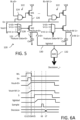
- Figure 6A illustrates a timing diagram for the in-memory compute operation for the case where the weight data is single bit data.
- the selected word line WL in each of the sub-arrays 114 is asserted.
- the voltage on the bit line BL then responds to the logic state of the stored bit in the memory cell 14.
- the enable signal En is asserted and the drain current I d dependent on the decoded feature data is integrated by the integration capacitor to generate the output voltage Vout.
- the enable signal En is deasserted and the integration time period ends.
- the selected word line WL is deasserted.
- time t4 may, in some cases, precede time t3 depending on the desired pulse width for the enable signal En.
- the switches S ⁇ 0> to S ⁇ M-1> are closed and the voltage Vglobal on the global output line 130 develops from the average of the column output voltages Vout ⁇ 0> to Vout ⁇ M-1>.
- the sampling circuit of the ADC converter circuit 132 is actuated to sample the voltage Vglobal on the global output line 130 for conversion and output of the decision output Decision at time t7.
- the output voltages Vout and the global voltage Vglobal are all reset.
- the computation tile circuit 120 can also be used when the weight data is multi-bit.
- the multiple bits (i.e., N bits) of the weight data are stored in the corresponding N memory cells 14 of each column in the sub-array 114 (where the least significant bit of the multi-bit weight data is stored in the memory cell 14 for the row with word line WL ⁇ 0> and the most significant bit of the multi-bit weight data is stored in the memory cell 14 for the row with word line WL ⁇ N-1>).
- the row controller circuit 118 sequentially selects the word lines WL ⁇ 0> through WL ⁇ N-1> for execution of the in-memory compute operation. With each word line selection, the enable signal En is also asserted.
- the pulse width of the enable signal En is binary weighted corresponding to the significance of the bit of the multi-bit weight data.
- the pulse width of the enable signal En increases with each successive word line selection (so that, for example, the pulse width of the enable signal when word line WL ⁇ 1> is asserted is twice as long as the pulse width of the enable signal En when word line WL ⁇ 0> is asserted, and the pulse width of the enable signal when word line WL ⁇ 2> is asserted is twice as long as the pulse width of the enable signal En when word line WL ⁇ 1> is asserted, etc.).
- Figure 6B illustrates a timing diagram for the in-memory compute operation for the case where the weight data is multi-bit data.
- the first word line WL ⁇ 0> in each of the sub-arrays 114 is selected and asserted.
- the voltage on the bit line BL then responds to the logic state of the stored least significant bit in the memory cell 14.
- the enable signal En is asserted with a first pulse width and the drain current I d dependent on the decoded feature data is integrated by the integration capacitor to generate the output voltage Vout.
- the enable signal En is deasserted and the integration time period for the least significant bit ends.
- the first word line WL ⁇ 0> is deasserted.
- time t4 may, in some cases, precede time t3 depending on the desired pulse width for the enable signal En.
- the second word line WL ⁇ 1> in each of the sub-arrays 114 is selected and asserted.
- the voltage on the bit line BL then responds to the logic state of the stored bit in the memory cell 14.
- the enable signal En is asserted with a second pulse width (twice as long as the first pulse width) and the drain current I d dependent on the decoded feature data is integrated by the integration capacitor to further develop the output voltage Vout.
- the enable signal En is deasserted and the integration time period for this bit ends.
- the second word line WL ⁇ 2> is deasserted. It will be noted that time t8 may, in some cases, precede time t7 depending on the desired pulse width for the enable signal En. The foregoing repeats through the assertion of the last word line WL(N-1) for the most significant bit and the assertion of the enable signal En with a pulse width that is 2 N times as long as the first pulse width.
- the switches S ⁇ 0> to S ⁇ M-1> are closed and the voltage Vglobal on the global output line 130 develops from the average of the column output voltages Vout ⁇ 0> to Vout ⁇ M-1>.
- the sampling circuit of the ADC converter circuit 132 is actuated to sample the voltage Vglobal on the global output line 130 for conversion and output of the decision output Decision at time t11.
- the output voltages Vout and the global voltage Vglobal are all reset.
- the multiple bits (i.e., N bits) of the weight data are again stored in the corresponding N memory cells 14 of each column in the sub-array 114.
- the row controller circuit 118 sequentially selects the word lines WL ⁇ 0> through WL ⁇ N-1> for execution of the in-memory compute operation. With each word line selection, the enable signal En is also asserted. Unlike the Figure 6B example, the pulse width of the enable signal En is constant for all assertions.
- the developed global output voltage is sampled and converted to a digital signal representing a partial sum for each asserted pair of word line pulse and enable signals.
- the digital signal processing function adds all the calculated partial sums produced by the ADC circuit to produce the digital output Decision.
- Figure 6C illustrates a timing diagram for the in-memory compute operation for the case where the weight data is multi-bit data.
- the first word line WL ⁇ 0> in each of the sub-arrays 114 is selected and asserted.
- the voltage on the bit line BL then responds to the logic state of the stored least significant bit in the memory cell 14.
- the enable signal En is asserted and the drain current I d dependent on the decoded feature data is integrated by the integration capacitor to generate the output voltage Vout.
- the enable signal En is deasserted and the integration time period for the least significant bit ends.
- the first word line WL ⁇ 0> is deasserted.
- time t4 may, in some cases, precede time t3 depending on the desired pulse width for the enable signal En.
- the switches S ⁇ 0> to S ⁇ M-1> are closed and the voltage Vglobal on the global output line 130 develops from the average of the column output voltages Vout ⁇ 0> to Vout ⁇ M-1>.
- the sampling circuit of the ADC converter circuit 132 is actuated to sample the voltage Vglobal on the global output line 130 for conversion and output of a first partial sum (P-Sum ⁇ 0>) at time t7.
- the output voltages Vout and the global voltage Vglobal are all reset.
- the second word line WL ⁇ 1> in each of the sub-arrays 114 is selected and asserted.
- the voltage on the bit line BL then responds to the logic state of the stored least significant bit in the memory cell 14.
- the enable signal En is asserted and the drain current I d dependent on the decoded feature data is integrated by the integration capacitor to generate the output voltage Vout.
- the enable signal En is deasserted and the integration time period for this bit ends.
- the second word line WL ⁇ 1> is deasserted. It will be noted that time t11 may, in some cases, precede time t10 depending on the desired pulse width for the enable signal En.
- the switches S ⁇ 0> to S ⁇ M-1> are closed and the voltage Vglobal on the global output line 130 develops from the average of the column output voltages Vout ⁇ 0> to Vout ⁇ M-1>.
- the sampling circuit of the ADC converter circuit 132 is actuated to sample the voltage Vglobal on the global output line 130 for conversion and output of a second partial sum (P-Sum ⁇ 1>) at time t14.
- the output voltages Vout and the global voltage Vglobal are all reset.
- a digital signal processing function can add the partial sums at time t20 and output the Decision.
- Each column compute circuit 122 includes a combinational logic circuit 124 configured to logically combine the weight data bit on the bit line BL with an enable signal En.
- the combinational logic circuit 124 is formed by a logic NAND gate. The output of the combinational logic circuit 124 is asserted (in this case logic low) when both the weight data bit and the enable signal En are logic high. The enable signal En is asserted logic high when the in-memory compute operation is being executed.
- the output of the combinational logic circuit 124 drives the gate of a p-channel MOS transistor M1 having a source coupled, preferably directly connected, to a supply voltage node Vdd and a drain coupled, preferably directly connected to an intermediate node 126.
- the transistor M1 is configured to function as a switching circuit.
- the column compute circuit 122 further includes a p-channel MOS transistor M2 having a source coupled, preferably directly connected, to the intermediate node 126 and a drain coupled, preferably directly connected, to an output node 128.
- An integration capacitor Cint has a first terminal coupled, preferably directly connected, to the output node 128 and a second terminal coupled, preferably directly connected, to a reference voltage node (for example, ground). To this point, the column compute circuit 122 is identical to that shown in Figure 5 .
- each column compute circuit 122 includes the K: 1 multiplexer circuit MUX whose output drives the gate of transistor M2.
- the K:1 multiplexer circuit MUX is shared by all column compute circuits 122 in a column.
- output of the K:1 multiplexer circuit MUX for the column drives the gates of all transistors M2 in that same column. This is possible since the feature data applied to the column compute circuits 122 for a given column is the same.
- a single K:1 multiplexer circuit MUX for that first column has K inputs configured to receive a set (Vset) of analog voltages V ⁇ 0> to V ⁇ K-1> and a selection input that receives J bits of the feature data (Feature Data ⁇ 0>).
- the output (signal gate ⁇ 0>) of the shared multiplexer circuit MUX is coupled, preferably directly connected, to drive the gate terminals of the MOS transistors M2.
- a single K:1 multiplexer circuit MUX for that last column has K inputs configured to receive analog voltages V ⁇ 0> to V ⁇ K-1> and a selection input that receives J bits of the feature data (Feature Data ⁇ M-1>).
- the output (signal gate ⁇ M-1>) of the shared multiplexer circuit MUX is coupled, preferably directly connected, to drive the gate terminals of the MOS transistors M2.
- FIG. 8 shows a schematic diagram of another embodiment for the in-memory computation circuit 200.
- the circuit 200 utilizes a static random access memory (SRAM) array 212 that is segmented (i.e., partitioned) into a plurality of sub-arrays 214.
- SRAM static random access memory
- Each sub-array 214(i), where i is the sub-array index from 0 to P-1 includes standard 6T SRAM memory cells 14 (see, Figure 2 ) arranged in a matrix format having N rows and M columns.
- a standard 8T memory cell or an SRAM with a similar functionality and topology could instead be used.
- Each memory cell 14 is programmed to store a bit of a computational weight or kernel data for an in-memory compute operation. Each bit of the computational weight has either a logic "1" or a logic "0" value.
- Each SRAM cell 14 includes a word line WL and a pair of complementary bit lines BLT and BLC.
- the 8T-type SRAM cell would additionally include a read word line RWL and a read bit line BLR.
- the cells 14 in a common row of each sub-array 114 are connected to each other through a common word line WL (and through the common read word line RWL in the 8T-type implementation).
- the cells 14 in a common column of each sub-array 214 are connected to each other through a common pair of complementary bit lines BLT and BLC (and through the common read bit line BLR in the 8T-type implementation).
- each word line WL, RWL is driven by a word line driver circuit 16 which may be implemented as a CMOS driver circuit (for example, a series connected p-channel and n-channel MOSFET transistor pair forming a logic inverter circuit).
- CMOS driver circuit for example, a series connected p-channel and n-channel MOSFET transistor pair forming a logic inverter circuit.
- word line WL ⁇ k> where k is a row index from 0 to N-1, coupled to the k-th row of memory cells 14.
- the memory cells 14 in a row are programmed to store M bits of multi-bit weight data for an in-memory compute operation (where the least significant bit of the multi-bit weight data is stored in the memory cell 14 for the first column with bit lines BLT ⁇ 0>, BLC ⁇ 0> and the most significant bit of the multi-bit weight data is stored in the memory cell 14 for the last column with bit lines BLT ⁇ M-1>, BLC ⁇ M-1>).
- Each bit of the computational weight has either a logic "1" or a logic "0" value. It will be noted that this arrangement for the storage of the multi-bit weight data is different from the implementation discussed previously where the N bits of multi-bit weight data for the in-memory compute operation were stored in the memory cells 14 of a column.
- the word line signals applied to the word lines, and driven by the word line driver circuits 16, are generated from feature data input to the in-memory computation circuit 200 and controlled by a row controller circuit 218.
- the row controller circuit 218 selects the word line WL for one row at a time in each sub-array 214 in connection with the execution of a given in-memory compute operation and applies a pulsed word line signal to that selected word line.
- the pulsed word line signals on the asserted individual word lines in the different sub-arrays 214 have a fixed pulse pulse.
- the width of the word line signal pulse is selected so that a full swing on the bit line BL is achieved when reading the bit of the weight data from the memory cell 14 (i.e., one of the complementary bit lines BLT or BLC will be fully discharge).
- the width of the word line signal pulse is selected so that a full swing on the bit line BL is achieved when reading the bit of the weight data from the memory cell 14 (i.e., one of the complementary bit lines BLT or BLC will be fully discharge).
- Figure 8 illustrates an example where the first word lines WL ⁇ 0> in each of the plurality of sub-arrays 214 are being simultaneously driven by fixed pulse width word line signals through the word line driver circuits 16 in response to the feature data for the in-memory compute operation.
- the row controller circuit 218 may sequentially select each of the word lines WL ⁇ 0> through WL ⁇ N-1> in connection with executing the in-memory compute operation.
- a computation tile circuit 220 for each sub-array 214 receives the logic state on one of the complementary bit lines BLT and BLC (and/or on the read bit line BLR) for each of the M columns. That bit line logic state corresponds to the logic state of one bit of the multi-bit weight data stored in the memory cell 14 which is accessed by the asserted word line signal pulse.
- the computation tile circuit 220 further receives the feature data for the in-memory compute operation from a feature data bus.
- a current digital-to-analog converter (I-DAC) circuit converts the digital feature data to an analog current that is selectively integrated as a function of the sensed logic state of the memory cell 14 to generate a column output voltage.
- I-DAC current digital-to-analog converter
- the column output voltages are averaged and the averaged voltage is sampled and converted by an analog-to-digital converter (ADC) circuit to produce a decision output from the computation tile 220.
- ADC analog-to-digital converter
- the in-memory compute operation being performed is essentially a dot-product operation of the feature data and the multi-bit weight data.
- the decision outputs Decision ⁇ 0> through Decision ⁇ P-1 > may be individually used or further combined in a subsequent digital signal processing (DSP) operation.
- DSP digital signal processing
- circuit 200 further includes conventional row decode, column decode, and read-write circuits known to those skilled in the art for use in connection with writing bits of the computational weight to, and reading bits of the computational weight from, the SRAM cells 14 of each sub-array 214 within the memory array 212.
- the computation tile 220 includes a column compute circuit 222 connected to the bit line BL (either BLT or BLC) of a corresponding column of the sub-array 214.
- Each column compute circuit 222 includes a combinational logic circuit 224 configured to logically combine the weight data bit on the bit line BL with an enable signal En.
- the combinational logic circuit 224 is formed by a logic NAND gate. The output of the combinational logic circuit 224 is asserted (in this case logic low) when both the weight data bit and the enable signal En are logic high.
- the enable signal En is asserted logic high when the in-memory compute operation is being executed.
- the output of the combinational logic circuit 224 drives the gate of a p-channel MOS transistor M1 having a source coupled, preferably directly connected, to a supply voltage node Vdd and a drain coupled, preferably directly connected to an intermediate node 226.
- the transistor M1 is configured to function as a switching circuit.
- the combinational logic circuit 224 and transistor M1 form a switched timing circuit where transistor M1 is turned on to provide the supply voltage Vdd at intermediate node 226 for a duration of time equal to the width of the enable signal En if the bit line BL is at logic 1.
- Each column compute circuit 222 further includes a current digital-to-analog converter (I-DAC) circuit coupled, preferably directly connected, to receive power from the intermediate node 226.
- the I-DAC circuit receives a set of analog voltages Vset and the bits of the feature data.
- the I-DAC circuit decodes the bits of the feature data to select one (or more) of the voltages from the set of voltages Vset for use in generating the output drain current I d .
- the output drain currents from the I-DAC circuits are applied to an output node 228 coupled, preferably directly connected, to a first terminal of an integration capacitor Cint.
- a second terminal of the integration capacitor Cint is coupled, preferably directly connected, to a reference voltage node (for example, ground).
- the integration capacitor Cint integrates the drain currents I d to generate an output voltage Vout at the output node 228.
- the integration time for the generated drain current(s) I d is controlled by the width of the enable signal En pulse.
- the output node 228 is selectively connected through a switch S ⁇ 0> to a global output line 230 that is coupled, preferably directly connected, to the input of an analog-to-digital converter (ADC) circuit 232.
- ADC analog-to-digital converter
- the ADC circuit 232 functions to sample and convert the voltage Vglobal on the global output line 230 to generate the digital decision output for the column compute circuit 222.
- the global output line 230 may, in some embodiments extend parallel to rows of the sub-array, and in other embodiments extend parallel to columns of the sub-arrays.
- the set of analog voltages Vset received by each I-DAC circuit in this embodiment where the weight data is multi-bit are different.
- the I-DAC circuit coupled to the first column associated with bit line BL ⁇ 0> receives a first set of analog voltages Vset(0)
- the I-DAC circuit coupled to the last column associated with bit line BL ⁇ M-1> receives an (M-1)th set of analog voltages Vset(M-1).
- FIG. 10 shows an embodiment for the I-DAC circuit used in the column compute circuit 222 of Figure 9 .
- the I-DAC circuit is configured for operation with two bit feature data (FD ⁇ _> ⁇ 1:0>).
- a p-channel MOS transistor Ma has a source coupled, preferably directly connected, to the intermediate node 226 and a drain coupled, preferably directly connected, to the output node 228.
- a p-channel MOS transistor Mb has a source coupled, preferably directly connected, to the intermediate node 226 and a drain coupled, preferably directly connected, to the output node 228.
- a p-channel MOS transistor Mc has a source coupled, preferably directly connected, to the supply voltage node Vdd and a drain coupled, preferably directly connected, to the gate of transistor Ma. The gate of the transistor Mc receives the less significant bit of the feature data FD ⁇ _> ⁇ 0>.
- a p-channel MOS transistor Md has a source coupled, preferably directly connected, to the supply voltage node Vdd and a drain coupled, preferably directly connected, to the gate of transistor Mb. The gate of the transistor Md receives the more significant bit of the feature data FD ⁇ _> ⁇ 1>.
- An n-channel MOS transistor Me has a drain coupled, preferably directly connected, to the gate of transistor Ma and a source coupled, preferably directly connected, to receive one of the voltages in the set of voltages Vset.
- the gate of the transistor Me receives the less significant bit of the feature data FD ⁇ _> ⁇ 0>.
- An n-channel MOS transistor Mf has a drain coupled, preferably directly connected, to the gate of transistor Mb and a source coupled, preferably directly connected, to receive another of the voltages in the set of voltages Vset.
- the gate of the transistor Mf receives the more significant bit of the feature data FD ⁇ _> ⁇ 1>.
- the first set of analog voltages Vset(0) includes the voltages Vset ⁇ 0> and Vset ⁇ 1> applied to the sources of transistors Me and Mf, respectively.
- the second set of analog voltages Vset(1) includes the voltages Vset ⁇ 2> and Vset ⁇ 3> applied to the sources of transistors Me and Mf, respectively.
- I-DAC circuit Operation of the I-DAC circuit is as follows: Assume first that both bits of the two bit feature data (FD ⁇ _> ⁇ 1:0>) are logic 0. In this case, transistors Mc and Md will both be turned on to apply Vdd to the gates of transistors Ma and Mb. As a result, transistors Ma and Mb will both be turned off and the drain currents I d will be zero (regardless of the logic state of the weight bit or the pulse of the enable signal En). It will be noted from the previous table that when both bits of the feature data are logic 0 there is no drain current output and the change in voltage integrated on the capacitor Cint is zero.
- transistor Mc is turned off and transistor Md is turned on.
- transistor Mb is also turned off and will not contribute a drain current to the output.
- transistor Ma can contribute a drain current dependent on two factors: a) the voltage at the gate of transistor Ma and b) whether the memory cell on the bit line is storing a logic 1 value for the bit of the weight data.
- the logic 1 state of the less significant bit of the two bit feature data (FD ⁇ _> ⁇ 1:0>) will cause transistor Me to turn on and the analog voltage Vset ⁇ 0> or Vset ⁇ 2> will be applied to the gate of transistor Ma to be converted by the transconductance of transistor Ma to a non-zero drain current.
- the transconductances from both the analog voltages Vset ⁇ 0> and Vset ⁇ 2> contribute to the drain current (which is applied for the duration of the pulse width of the enable signal En if the weight bit on the bit line is logic 1). This is shown in the previous table with the drain current 3*Iref and the resulting change in integrated voltage on the integration capacitor Cint of 3 ⁇ ⁇ V.
- transistor Md is turned off and transistor Mc is turned on.
- transistor Ma is also turned off and will not contribute a drain current to the output.
- transistor Mb can contribute a drain current dependent on two factors: a) the voltage at the gate of transistor Mb and b) whether the memory cell on the bit line is storing a logic 1 value for the bit of the weight data.
- the logic 1 state of the less significant bit of the two bit feature data (FD ⁇ _> ⁇ 1:0>) will cause transistor Mf to turn on and the analog voltage Vset ⁇ 1> or Vset ⁇ 3> will be applied to the gate of transistor Mb to be converted by the transconductance of transistor Mb to a non-zero drain current.
- the transconductances from both the analog voltages Vset ⁇ 1> and Vset ⁇ 3> contribute to the drain current (which is applied for the duration of the pulse width of the enable signal En if the weight bit on the bit line is logic 1). This is shown in the previous table with the drain current 6*Iref and the resulting change in integrated voltage on the integration capacitor Cint of 6 ⁇ ⁇ V.
- both bits of the two bit feature data are logic 1.
- transistor Mc is turned off and transistor Md is turned off.
- transistors Ma and Mb can contribute a drain current dependent on two factors: a) the voltage at the gate of transistor Mb and b) whether the memory cell on the bit line is storing a logic 1 value for the bit of the weight data.
- the logic 1 state of the less significant bit of the two bit feature data (FD ⁇ _> ⁇ 1:0>) will cause transistor Me to turn on and the analog voltage Vset ⁇ 0> or Vset ⁇ 2> will be applied to the gate of transistor Ma to be converted by the transconductance of transistor Ma to a non-zero drain current.
- the logic 1 state of the less significant bit of the two bit feature data (FD ⁇ _> ⁇ 1:0>) will cause transistor Mf to turn on and the analog voltage Vset ⁇ 1> or Vset ⁇ 3> will be applied to the gate of transistor Mb to be converted by the transconductance of transistor Mb to a non-zero drain current.
- the transconductances from the analog voltages V ⁇ 0> and Vset ⁇ 2> contribute to the drain current (which is applied for the duration of the pulse width of the enable signal En if the weight bit on the bit line is logic 1). This is shown in the previous table with the drain current 3 ⁇ Iref and the resulting change in integrated voltage on the integration capacitor Cint of 3 ⁇ ⁇ V.
- the transconductances from the analog voltages Vset ⁇ 1> and Vset ⁇ 3> contributes to the drain current (which is applied for the duration of the pulse width of the enable signal En if the weight bit on the bit line is logic 1). This is shown in the previous table with the drain current 6*Iref and the resulting change in integrated voltage on the integration capacitor Cint of 6 ⁇ ⁇ V.
- the transconductances from the analog voltages Vset ⁇ 0>, Vset ⁇ 1>, Vset ⁇ 2> and Vset ⁇ 3> contribute to the drain current (which is applied for the duration of the pulse width of the enable signal En if the weight bit on the bit line is logic 1). This is shown in the previous table with the drain current 9 ⁇ Iref and the resulting change in integrated voltage on the integration capacitor Cint of 9 ⁇ ⁇ V.
- the architecture of the in-memory compute system can be designed to have the global output line GOL (reference 130, 230) extend in either the row direction or the column direction.
- Figure 11 shows a layout for the sub-arrays and the column compute circuits for the computation tiles arranged with the global output lines GOL extending in the row direction (i.e., parallel to rows of the sub-arrays). The feature data in this implementation is applied to the column compute circuits in the column direction.
- Figure 12 shows a layout for the sub-arrays and the column compute circuits for the computation tiles arranged with the global output lines GOL extending in the column direction (i.e., parallel to columns of the sub-arrays). The feature data in this implementation is applied to the column compute circuits in the row direction.
Abstract
An in-memory computation circuit includes a memory array including sub-arrays of with SRAM cells connected in rows by word lines and in columns by bit lines. A row controller circuit selectively actuates word lines across the sub-arrays for an in-memory compute operation. A computation tile circuit for each sub-array includes a column compute circuit for each bit line. Each column compute circuit includes a switched timing circuit that is actuated in response to weight data on the bit line for a duration of time set by an in-memory compute operation enable signal. A current digital-to-analog converter powered by the switched timing circuit operates to generate a drain current having a magnitude controlled by bits of feature data for the in-memory compute operation. The drain current is integrated to generate an output voltage.
Description
- This application claims priority from
United States Provisional Application for Patent No. 63/345,663, filed May 25, 2022 - Embodiments relate to an in-memory computation circuit utilizing a static random access memory (SRAM) array and, in particular, to a segmented architecture of the array with a local compute read based on weighted current.
- Reference is made to
Figure 1 which shows a schematic diagram of an in-memory computation circuit 10. Thecircuit 10 utilizes a static random access memory (SRAM)array 12 formed by standard 6TSRAM memory cells 14 arranged in a matrix format having N rows and M columns. As an alternative, a standard 8T memory cell or an SRAM with a similar functionality and topology could instead be used. Eachmemory cell 14 is programmed to store a bit of a computational weight or kernel data for an in-memory compute operation. In this context, the in-memory compute operation is understood to be a form of a high dimensional Matrix Vector Multiplication (MVM) supporting multi-bit weights that are stored in multiple bit cells of the memory. The group of bit cells (in the case of a multibit weight) can be considered as a virtual synaptic element. Each bit of the computational weight has either a logic " 1 " or a logic "0" value. - Each
SRAM cell 14 includes a word line WL and a pair of complementary bit lines BLT and BLC. The 8T-type SRAM cell would additionally include a read word line RWL and a read bit line BLR. Thecells 14 in a common row of the matrix are connected to each other through a common word line WL (and through the common read word line RWL in the 8T-type implementation). Thecells 14 in a common column of the matrix are connected to each other through a common pair of complementary bit lines BLT and BLC (and through the common read bit line BLR in the 8T-type implementation). Each word line WL, RWL is driven by a wordline driver circuit 16 which may be implemented as a CMOS driver circuit (for example, a series connected p-channel and n-channel MOSFET transistor pair forming a logic inverter circuit). The word line signals applied to the word lines, and driven by the wordline driver circuits 16, are generated from feature data input to the in-memory computation circuit 10 and controlled by arow controller circuit 18. Acolumn processing circuit 20 senses the analog current signals on the pairs of complementary bit lines BLT and BLC (and/or on the read bit line BLR) for the M columns and generates a decision output for the in-memory compute operation from those analog current signals. Thecolumn processing circuit 20 can be implemented to support processing where the analog current signals on the columns are first processed individually and then followed by a recombination of multiple column outputs. - Although not explicitly shown in
Figure 1 , it will be understood that thecircuit 10 further includes conventional row decode, column decode, and read-write circuits known to those skilled in the art for use in connection with writing bits of the computational weight to, and reading bits of the computational weight from, theSRAM cells 14 of thememory array 12. - With reference now to
Figure 2 , eachmemory cell 14 includes twocross-coupled CMOS inverters inverters cell 14 further includes two transfer (passgate)transistors transistor 26 is connected between the true data storage node QT and a node associated with a true bit line BLT. The source-drain path oftransistor 28 is connected between the complement data storage node QC and a node associated with a complement bit line BLC. The source terminals of the p-channel transistors inverter channel transistors inverter Figure 2 is specific to the use of 6T-type cells, those skilled in the art recognize that the 8T-type cell is similarly configured and would further include a signal path that is coupled to one of the storage nodes and includes a transfer (passgate) transistor coupled to the read bit line BLR and gate driven by the signal on the read word line RWL. The wordline driver circuit 16 is also typically coupled to receive the high supply voltage (Vdd) at the high supply node and is referenced to the low supply voltage (Gnd) at the low supply node. - The
row controller circuit 18 receives the feature data for the in-memory compute operation and in response thereto performs the function of selecting which ones of the word lines WL<0> to WL<N-1> are to be simultaneously accessed (or actuated) in parallel during an in-memory compute operation, and further functions to control application of pulsed signals to the word lines in accordance with that in-memory compute operation.Figure 1 illustrates, by way of example only, the simultaneous actuation of all N word lines with the pulsed word line signals, it being understood that in-memory compute operations may instead utilize a simultaneous actuation of fewer than all rows of the SRAM array. The analog signals on a given pair of complementary bit lines BLT and BLC (or on the read bit line RBL in the 8T-type implementation) are dependent on the logic state of the bits of the computational weight stored in thememory cells 14 of the corresponding column and the width(s) of the pulsed word line signals applied to thosememory cells 14. - The implementation illustrated in
Figure 1 shows an example in the form of a pulse width modulation (PWM) for the applied word line signals for the in-memory compute operation dependent on the received feature data. The use of PWM or period pulse modulation (PTM) for the applied word line signals is a common technique used for the in-memory compute operation based on the linearity of the vector for the multiply-accumulation (MAC) operation. The pulsed word line signal format can be further evolved as an encoded pulse train to manage block sparsity of the feature data of the in-memory compute operation. It is accordingly recognized that an arbitrary set of encoding schemes for the applied word line signals can be used when simultaneously driving multiple word lines. Furthermore, in a simpler implementation, it will be understood that all applied word line signals in the simultaneous actuation may instead have a same pulse width. -
Figure 3 is a timing diagram showing simultaneous application of the example pulse width modulated word line signals to plural rows ofmemory cells 14 in theSRAM array 12 for a given in-memory compute operation, and the development over time of voltages Va,T and Va,C on one corresponding pair of complementary bit lines BLT and BLC, respectively, in response to sinking of cell read current due to the pulse width(s) of those word line signals and the logic state of the bits of the computational weight stored in thememory cells 14. The representation of the voltage Va levels as shown is just an example. After completion of the computation cycle of the in-memory compute operation, the voltage Va levels return to the bit line precharge Vdd level. It will be noted that a risk exists that the voltage on at least one of the bit lines BLT and BLC may fall from the Vdd voltage to a level below the write margin where an unwanted data flip occurs with respect to the stored data bit value in one of thememory cells 14 of the column. For example, a logic "1" state stored in thecell 14 of a column may be flipped to a logic "0" state. This data flip introduces a data error in the computational weight stored in the memory cells, thus jeopardizing the accuracy of subsequent in-memory compute operations. - The unwanted data flip that occurs due to an excess of bit line voltage lowering is mainly an effect of the simultaneous parallel access of the word lines in matrix vector multiplication mode during the in-memory compute operation. This problem is different from normal data flip of an SRAM bit cell due to Static-Noise-Margin (SNM) issues which happens in serial bit cell access when the bit line is close to the level of the supply voltage Vdd. During serial access, the normal data flip is instead caused by a ground bounce of the data storage nodes QT or QC.
- In an embodiment, an in-memory computation circuit comprises: a memory array including a plurality of sub-arrays, wherein each sub-array includes static random access memory (SRAM) cells arranged in a matrix with plural rows and plural columns, each row including a word line connected to the SRAM cells of the row, and each column including a bit line connected to the SRAM cells of the column, said SRAM cells storing bits of weight data for an in-memory compute operation; a word line driver circuit for each row having an output connected to drive the word line of the row; and a row controller circuit configured to simultaneously actuate at least one word line for each sub-array by applying pulses through the word line driver circuits to the word lines for the in-memory compute operation.
- A computation tile circuit for each sub-array includes a plurality of column compute circuits coupled to the bit lines, respectively, of the columns of the sub-array. Each column compute circuit comprises: a switched timing circuit that is actuated in response to a first logic state of the weight data on the bit line for a duration of time set by an enable signal for the in-memory compute operation; a current digital-to-analog converter (I-DAC) powered by actuation of the switched timing circuit and configured to generate a drain current having a magnitude controlled by bits of feature data for the in-memory compute operation; and an integration circuit configured to integrate the drain current and generate an output voltage.
- For a better understanding of the embodiments, reference will now be made by way of example only to the accompanying figures in which:
-
Figure 1 is a schematic diagram of an in-memory computation circuit; -
Figure 2 is a circuit diagram of a standard 6T static random access memory (SRAM) cell as used the memory array of the in-memory computation circuit shown inFigure 1 ; -
Figure 3 is a timing diagram illustrating an in-memory compute operation; -
Figure 4 is a schematic diagram of an in-memory computation circuit; -
Figure 5 is a circuit diagram for an embodiment of a computation tile used in the circuit ofFigure 4 ; -
Figures 6A ,6B and6C are timing diagrams illustrating operation of theFigure 5 circuit; -
Figure 7 shows an alternative embodiment of the computation tile for the circuit ofFigure 4 ; -
Figure 8 is a schematic diagram of another embodiment for the in-memory computation circuit; -
Figure 9 is a circuit diagram for an embodiment of a computation tile used in the circuit ofFigure 8 ; -
Figure 10 is circuit diagram for an embodiment of a current digital-to-analog converter (I-DAC circuit) used in the circuit ofFigure 9 ; and -
Figures 11-12 illustrate alternative architectures for the in-memory compute circuit. - Reference is now made to
Figure 4 which shows a schematic diagram of an in-memory computation circuit 100. Thecircuit 100 utilizes a static random access memory (SRAM)array 112 that is segmented (i.e., partitioned) into a plurality ofsub-arrays 114. In this example, there are P sub-arrays 114(0) to 114(P-1) within thearray 112. Each sub-array 114(i), where i is the sub-array index from 0 to P-1, includes standard 6T SRAM memory cells 14 (see,Figure 2 ) arranged in a matrix format having N rows and M columns. As an alternative, a standard 8T memory cell or an SRAM with a similar functionality and topology could instead be used. Eachmemory cell 14 is programmed to store a bit of a computational weight or kernel data for an in-memory compute operation. Each bit of the computational weight has either a logic "1" or a logic "0" value. - Each
SRAM cell 14 includes a word line WL and a pair of complementary bit lines BLT and BLC. The 8T-type SRAM cell would additionally include a read word line RWL and a read bit line BLR. Thecells 14 in a common row of each sub-array 114 are connected to each other through a common word line WL (and through the common read word line RWL in the 8T-type implementation). Thecells 14 in a common column of each sub-array 114 are connected to each other through a common pair of complementary bit lines BLT and BLC (and through the common read bit line BLR in the 8T-type implementation). In the illustrated example, for a given sub-array 114(i) there is a true bit line BLTi<j>, where j is a column index from 0 to M-1, coupled to the j-th column ofmemory cells 14, and there is a complement bit line BLCi<j> coupled to that same j-th column ofmemory cells 14. Each word line WL, RWL is driven by a wordline driver circuit 16 which may be implemented as a CMOS driver circuit (for example, a series connected p-channel and n-channel MOSFET transistor pair forming a logic inverter circuit). In the illustrated example, for a given sub-array 114(i), there is a word line WL<k>, where k is a row index from 0 to N-1, coupled to the k-th row ofmemory cells 14. - The word line signals applied to the word lines, and driven by the word
line driver circuits 16, are generated from feature data input to the in-memory computation circuit 100 and controlled by arow controller circuit 118. In response to the feature data, therow controller circuit 118 selects the word line WL for one row at a time in each sub-array 114 in connection with the execution of a given in-memory compute operation and applies a pulsed word line signal to that selected word line. The pulsed word line signals on the asserted individual word lines in thedifferent sub-arrays 114 have a fixed pulse width. In a preferred embodiment, the width of the word line signal pulse is selected so that a full swing on the bit line BL is achieved when reading the bit of the weight data from the memory cell 14 (i.e., one of the complementary bit lines BLT or BLC will be fully discharge). Thus, in response to the assertion of the word line signal, and as a function of the logic state of the weight bit stored in the accessedmemory cell 14, local bit line voltages VL develop on the complementary bit lines BLT and BLC. -
Figure 4 illustrates an example where the first word lines WL<0> in each of the plurality ofsub-arrays 114 are being simultaneously driven by fixed pulse width word line signals through the wordline driver circuits 16 in response to the feature data for the in-memory compute operation. In an embodiment, therow controller circuit 118 may sequentially select each of the word lines WL<0> through WL<N-1> in connection with executing the in-memory compute operation. In any case, it is preferable that only one word line (not necessarily the same word line) at a time persub-array 114 be asserted in order to minimize the risk of inadvertent bit flip within each sub-array 114 during the in-memory compute operation. - A
computation tile circuit 120 for each sub-array 114 receives the logic state on one of the complementary bit lines BLT and BLC (and/or on the read bit line BLR) for each of the M columns. That bit line logic state corresponds to the logic state of the weight data stored in thememory cell 14 which is accessed by the asserted word line signal pulse. The width of the word line signal pulse is selected so that a full swing on the bit line is achieved when reading the bit of the weight data from thememory cell 14. Thecomputation tile circuit 120 further receives bit(s) of the feature data for the in-memory compute operation over afeature data bus 121. Note here that this is different from the implementation ofFigure 1 where the bits of the feature data are instead input to the row controller for controlling the generation of the pulse width modulated word line signals. A current digital-to-analog converter (I-DAC) circuit converts the digital feature data to an analog drain current Id having a magnitude modulated by the bit(s) of the feature data and that drain current Id is integrated as a function of the sensed logic state of thememory cell 14 to generate a column output voltage. The column output voltages generated by thecomputation tile circuit 120 are then averaged and that averaged voltage is sampled for conversion by an analog-to-digital converter (ADC) circuit to produce a digital decision output from thecomputation tile circuit 120. The in-memory compute operation being performed is essentially a dot-product operation of the feature data and the weight data. The decision outputs Decision<0> through Decision <P-1 > may be individually used or further combined in a subsequent digital signal processing (DSP) operation. - Although not explicitly shown in
Figure 4 , it will be understood that thecircuit 100 further includes conventional row decode, column decode, and read-write circuits known to those skilled in the art for use in connection with writing bits of the computational weight to, and reading bits of the computational weight from, theSRAM cells 14 of each sub-array 114 within thememory array 112. - Reference is now made to
Figure 5 which illustrates a circuit diagram for an embodiment of thecomputation tile circuit 120. Thecomputation tile circuit 120 includes a plurality of column computecircuits 122, with eachcircuit 122 connected to the bit line BL (either BLT or BLC) of a corresponding column of the sub-array 114. Eachcolumn compute circuit 122 includes acombinational logic circuit 124 configured to logically combine the weight data bit on the bit line BL (i.e., read from the accessed memory cell 14) with an enable signal En. In this embodiment, thecombinational logic circuit 124 is formed by a logic NAND gate. The output of thecombinational logic circuit 124 is a gate control signal that is asserted (in this case logic low) when both the weight data bit and the enable signal En are logic high. The enable signal En is asserted logic high when the in-memory compute operation is being executed, and the width of the enable signal En pulse corresponds to an integration time period for the in-memory compute operation with a timing generally corresponding to when the word line signal pulses are being generated. The output of thecombinational logic circuit 124 drives the gate of a p-channel MOS transistor M1 having a source coupled, preferably directly connected, to a supply voltage node Vdd and a drain coupled, preferably directly connected to anintermediate node 126. The transistor M1 is configured to function as a switching circuit. Thecombinational logic circuit 124 and transistor M1 thus form a switched timing circuit where transistor M1 is turned on, if the bit line BL is atlogic 1, to provide the supply voltage Vdd atintermediate node 126 for a duration of time equal to the width of the enable signal En. - The
column compute circuit 122 further includes a p-channel MOS transistor M2 having a source coupled, preferably directly connected, to theintermediate node 126 and a drain coupled, preferably directly connected, to anoutput node 128. An integration capacitor Cint has a first terminal coupled, preferably directly connected, to theoutput node 128 and a second terminal coupled, preferably directly connected, to a reference voltage node (for example, ground). Although not specifically illustrated, it will be understood that suitable circuitry for discharging (i.e., resetting) the capacitor Cint as necessary is provided. The gate of transistor M2 is driven by a voltage generated at the output of a K: 1 multiplexer circuit MUX. The K inputs of the multiplexer circuit MUX receive a set (Vset) of analog voltages V<0> to V<K-1>. The selection input of the multiplexer circuit MUX receives J bits of the feature data (where K=2J) from thefeature data bus 121. The multiplexer circuit MUX decodes the J bits of the feature data to select one of the K analog voltages of Vset for application to the gate of transistor M2. The transconductance of the transistor M2 converts the level of the analog voltage at the gate to output a drain current Id that is sourced to theoutput node 128 when, as controlled by the switched timing circuit, both the weight data bit and the enable signal En are logic high. The magnitude of the drain current Id is modulated as a function of the decoded J bits of the feature data and the selected analog voltage V. The integration capacitor Cint integrates this drain current Id to generate the column output voltage Vout at theoutput node 128. The multiplexer circuit MUX and transistor M2 thus form a current digital-to-analog converter (I-DAC) circuit that is selectively powered for actuation by the switched timing circuit and having an output current Id whose magnitude is modulated as a function of the bit(s) of the feature data. - The
output nodes 128 of thecolumn compute circuits 122<0> to 122<M-1> are selectively connected through switches S<0> to S<M-1>, respectively, to aglobal output line 130 that is coupled, preferably directly connected, to the input of an analog-to-digital converter (ADC)circuit 132. In this example implementation of thecomputation tile circuit 120, theglobal output line 130 extends parallel to the row direction of the sub-array 114 (although in other implementations theglobal output line 130 could connect to column compute circuits along columns of the array 112). TheADC circuit 132 functions to sample and convert the voltage Vglobal on theglobal output line 130 to generate the digital decision output for thecomputation tile circuit 120. The switches S<0> to S<M-1> are simultaneously actuated for the in-memory compute operation and the voltage Vglobal on theglobal output line 130 at the input of theADC circuit 132 is the average of the output voltages Vout<0> to Vout<M-1>. - The
combinational logic circuit 124, MOS transistors M1 and M2 and multiplexer MUX form a switched current digital-to-analog converter (I-DAC) circuit where the output drain current Id has a magnitude generated as a function of the product of the weight bit and the feature data (in other words, having a magnitude that is modulated as a function of the bit(s) of the feature data), and which has a duration of time that is dependent on the enable signal En. The integration time for the generated drain current Id is controlled by the width of the enable signal En pulse. - The following table illustrates operation of each
column compute circuit 122 in an example with a single bit weight and two bit feature data:Feature Data Weight Vgate Drain Current Output Voltage 1 1 1 V<3> 3∗ Iref 3∗ ΔV 1 0 V<2> 2∗ Iref 2∗ ΔV 0 1 V<1> 1∗ Iref 1∗ ΔV 0 0 V<0> 0 0 1 1 0 V<3> 0 0 1 0 V<2> 0 0 0 1 V<1> 0 0 0 0 V<0> 0 0 - Those skilled in the art will recognize that the foregoing can be extended to any desired number of bits for the feature data.
- Operation of the I-DAC circuit is as follows: Assume first that the weight bit on the bit line BL is
logic 0. In this case, thecombinational logic circuit 124 will output alogic 1 for application to the transistor M1. As a result, transistor M1 is turned off, no power is provided to the transistor M2 and the drain current Id output will be zero. It will be noted from the previous table that when the weight bit islogic 0 there is no drain current output and the integrated change in voltage on the capacitor Cint is zero. - Next, assume that the weight bit on the bit line is
logic 1. In this case, thecombinational logic circuit 124 will output alogic 0 for application to the transistor M1 for a duration of time controlled by the pulse width of the enable signal En. As a result, transistor M1 is turned on and power is provided to the transistor M2. - Now, assume that both bits of the two bit feature data (Feature Data<_> < 1:0>) are
logic 0. In this case, the multiplexer MUX decodes bits <0,0> of the feature data and selects the voltage V<0> for application to the gate of transistor M2. The transconductance of transistor M2 converts the voltage V<0> to a drain current Id having a zero magnitude. It will be noted from the previous table that when the weight bit islogic 1 and both feature data bits arelogic 0 there is no drain current output and the integrated change in voltage on the capacitor Cint is zero. - Now, assume that the less significant bit of the two bit feature data (Feature Data<_><1:0>) is
logic 1 and the more significant bit of the two bit feature data (Feature Data<_><1:0>) islogic 0. In this case, the multiplexer MUX decodes bits <0,1> of the feature data and selects the voltage V<1> for application to the gate of transistor M2. The transconductance of transistor M2 converts the voltage V <1> to a drain current Id having a first magnitude (1∗Iref). It will be noted from the previous table that when the weight bit islogic 1 and the feature data bits are <0,1> there is a drain current Id=1∗Iref output and the change in voltage on the capacitor Cint due to the integration of current Id over the pulse width of the enable signal En is 1∗ΔV. - Now, assume that the more significant bit of the two bit feature data (Feature Data<_><1:0>) is
logic 1 and the less significant bit of the two bit feature data (Feature Data<_><1:0>) islogic 0. In this case, the multiplexer MUX decodes bits <1,0> of the feature data and selects the voltage V<2> for application to the gate of transistor M2. The transconductance of transistor M2 converts the voltage V<2> to a drain current Id having a second magnitude (2∗Iref). It will be noted from the previous table that when the weight bit islogic 1 and the feature data bits are <1,0> there is a drain current Id=2∗Iref output and the change in voltage on the capacitor Cint due to the integration of current Id over the pulse width of the enable signal En is 2∗ΔV. - Now, assume that both bits of the two bit feature data (Feature Data<_> < 1:0>) are
logic 1. In this case, the multiplexer MUX decodes bits <1,1> of the feature data and selects the voltage V<3> for application to the gate of transistor M2. The transconductance of transistor M2 converts the voltage V<3> to a drain current Id having a third magnitude (3*Iref). It will be noted from the previous table that when the weight bit islogic 1 and both feature data bits are <1,1> there is a drain current Id=3∗Iref output and the change in voltage on the capacitor Cint due to the integration of current Id over the pulse width of the enable signal En is 3∗ΔV. -
Figure 6A illustrates a timing diagram for the in-memory compute operation for the case where the weight data is single bit data. At time t1, the selected word line WL in each of the sub-arrays 114 is asserted. The voltage on the bit line BL then responds to the logic state of the stored bit in thememory cell 14. At time t2, the enable signal En is asserted and the drain current Id dependent on the decoded feature data is integrated by the integration capacitor to generate the output voltage Vout. At time t3, the enable signal En is deasserted and the integration time period ends. At time t4, the selected word line WL is deasserted. It will be noted that time t4 may, in some cases, precede time t3 depending on the desired pulse width for the enable signal En. At time t5, the switches S<0> to S<M-1> are closed and the voltage Vglobal on theglobal output line 130 develops from the average of the column output voltages Vout<0> to Vout<M-1>. At time t6, the sampling circuit of theADC converter circuit 132 is actuated to sample the voltage Vglobal on theglobal output line 130 for conversion and output of the decision output Decision at time t7. The output voltages Vout and the global voltage Vglobal are all reset. - The
computation tile circuit 120 can also be used when the weight data is multi-bit. In such a case, the multiple bits (i.e., N bits) of the weight data are stored in the correspondingN memory cells 14 of each column in the sub-array 114 (where the least significant bit of the multi-bit weight data is stored in thememory cell 14 for the row with word line WL<0> and the most significant bit of the multi-bit weight data is stored in thememory cell 14 for the row with word line WL<N-1>). Therow controller circuit 118 sequentially selects the word lines WL<0> through WL<N-1> for execution of the in-memory compute operation. With each word line selection, the enable signal En is also asserted. However, the pulse width of the enable signal En is binary weighted corresponding to the significance of the bit of the multi-bit weight data. As an example, the pulse width of the enable signal En increases with each successive word line selection (so that, for example, the pulse width of the enable signal when word line WL<1> is asserted is twice as long as the pulse width of the enable signal En when word line WL<0> is asserted, and the pulse width of the enable signal when word line WL<2> is asserted is twice as long as the pulse width of the enable signal En when word line WL<1> is asserted, etc.). -
Figure 6B illustrates a timing diagram for the in-memory compute operation for the case where the weight data is multi-bit data. At time t1, the first word line WL<0> in each of the sub-arrays 114 is selected and asserted. The voltage on the bit line BL then responds to the logic state of the stored least significant bit in thememory cell 14. At time t2, the enable signal En is asserted with a first pulse width and the drain current Id dependent on the decoded feature data is integrated by the integration capacitor to generate the output voltage Vout. At time t3, the enable signal En is deasserted and the integration time period for the least significant bit ends. At time t4, the first word line WL<0> is deasserted. It will be noted that time t4 may, in some cases, precede time t3 depending on the desired pulse width for the enable signal En. At time t5, the second word line WL<1> in each of the sub-arrays 114 is selected and asserted. The voltage on the bit line BL then responds to the logic state of the stored bit in thememory cell 14. At time t6, the enable signal En is asserted with a second pulse width (twice as long as the first pulse width) and the drain current Id dependent on the decoded feature data is integrated by the integration capacitor to further develop the output voltage Vout. At time t7, the enable signal En is deasserted and the integration time period for this bit ends. At time t8, the second word line WL<2> is deasserted. It will be noted that time t8 may, in some cases, precede time t7 depending on the desired pulse width for the enable signal En. The foregoing repeats through the assertion of the last word line WL(N-1) for the most significant bit and the assertion of the enable signal En with a pulse width that is 2N times as long as the first pulse width. At time t9, the switches S<0> to S<M-1> are closed and the voltage Vglobal on theglobal output line 130 develops from the average of the column output voltages Vout<0> to Vout<M-1>. At time t10, the sampling circuit of theADC converter circuit 132 is actuated to sample the voltage Vglobal on theglobal output line 130 for conversion and output of the decision output Decision at time t11. The output voltages Vout and the global voltage Vglobal are all reset. - In an alternative implementation for the
computation tile circuit 120 to process multi-bit weight data, the multiple bits (i.e., N bits) of the weight data are again stored in the correspondingN memory cells 14 of each column in the sub-array 114. Therow controller circuit 118 sequentially selects the word lines WL<0> through WL<N-1> for execution of the in-memory compute operation. With each word line selection, the enable signal En is also asserted. Unlike theFigure 6B example, the pulse width of the enable signal En is constant for all assertions. In this case, the developed global output voltage is sampled and converted to a digital signal representing a partial sum for each asserted pair of word line pulse and enable signals. Following the processing associated with the last word line WL<N-1> and the determination of its associated partial sum, the digital signal processing function adds all the calculated partial sums produced by the ADC circuit to produce the digital output Decision. -
Figure 6C illustrates a timing diagram for the in-memory compute operation for the case where the weight data is multi-bit data. At time t1, the first word line WL<0> in each of the sub-arrays 114 is selected and asserted. The voltage on the bit line BL then responds to the logic state of the stored least significant bit in thememory cell 14. At time t2, the enable signal En is asserted and the drain current Id dependent on the decoded feature data is integrated by the integration capacitor to generate the output voltage Vout. At time t3, the enable signal En is deasserted and the integration time period for the least significant bit ends. At time t4, the first word line WL<0> is deasserted. It will be noted that time t4 may, in some cases, precede time t3 depending on the desired pulse width for the enable signal En. At time t5, the switches S<0> to S<M-1> are closed and the voltage Vglobal on theglobal output line 130 develops from the average of the column output voltages Vout<0> to Vout<M-1>. At time t6, the sampling circuit of theADC converter circuit 132 is actuated to sample the voltage Vglobal on theglobal output line 130 for conversion and output of a first partial sum (P-Sum<0>) at time t7. The output voltages Vout and the global voltage Vglobal are all reset. - At time t8, the second word line WL<1> in each of the sub-arrays 114 is selected and asserted. The voltage on the bit line BL then responds to the logic state of the stored least significant bit in the
memory cell 14. At time t9, the enable signal En is asserted and the drain current Id dependent on the decoded feature data is integrated by the integration capacitor to generate the output voltage Vout. At time t10, the enable signal En is deasserted and the integration time period for this bit ends. At time t11, the second word line WL< 1> is deasserted. It will be noted that time t11 may, in some cases, precede time t10 depending on the desired pulse width for the enable signal En. At time t12, the switches S<0> to S<M-1> are closed and the voltage Vglobal on theglobal output line 130 develops from the average of the column output voltages Vout<0> to Vout<M-1>. At time t13, the sampling circuit of theADC converter circuit 132 is actuated to sample the voltage Vglobal on theglobal output line 130 for conversion and output of a second partial sum (P-Sum< 1>) at time t14. The output voltages Vout and the global voltage Vglobal are all reset. - The foregoing repeats through the assertion of the last word line WL(N-1) for the most significant bit (at time t15) and the assertion of the enable signal En (at time t16). At time t17, the switches S<0> to S<M-1> are closed and the voltage Vglobal on the
global output line 130 develops from the average of the column output voltages Vout<0> to Vout<M-1>. At time t18, the sampling circuit of theADC converter circuit 132 is actuated to sample the voltage Vglobal on theglobal output line 130 for conversion and output of a last partial sum (P-Sum<N-1>) at time t19. The output voltages Vout and the global voltage Vglobal are all reset. - Once all of the partial sums P-Sum<0> to P-Sum<N-1> have been determined (and saved in memory of the ADC circuit or the DSP circuit), a digital signal processing function can add the partial sums at time t20 and output the Decision.
- Reference is now made to
Figure 7 which shows an alternative embodiment of thecomputation tile circuit 120. Eachcolumn compute circuit 122 includes acombinational logic circuit 124 configured to logically combine the weight data bit on the bit line BL with an enable signal En. In this embodiment, thecombinational logic circuit 124 is formed by a logic NAND gate. The output of thecombinational logic circuit 124 is asserted (in this case logic low) when both the weight data bit and the enable signal En are logic high. The enable signal En is asserted logic high when the in-memory compute operation is being executed. The output of thecombinational logic circuit 124 drives the gate of a p-channel MOS transistor M1 having a source coupled, preferably directly connected, to a supply voltage node Vdd and a drain coupled, preferably directly connected to anintermediate node 126. The transistor M1 is configured to function as a switching circuit. - The
column compute circuit 122 further includes a p-channel MOS transistor M2 having a source coupled, preferably directly connected, to theintermediate node 126 and a drain coupled, preferably directly connected, to anoutput node 128. An integration capacitor Cint has a first terminal coupled, preferably directly connected, to theoutput node 128 and a second terminal coupled, preferably directly connected, to a reference voltage node (for example, ground). To this point, thecolumn compute circuit 122 is identical to that shown inFigure 5 . - It will be noted that in the embodiment of
Figure 5 , eachcolumn compute circuit 122 includes the K: 1 multiplexer circuit MUX whose output drives the gate of transistor M2. In the embodiment ofFigure 7 , however, the K:1 multiplexer circuit MUX is shared by all column computecircuits 122 in a column. Thus, in this embodiment, output of the K:1 multiplexer circuit MUX for the column drives the gates of all transistors M2 in that same column. This is possible since the feature data applied to thecolumn compute circuits 122 for a given column is the same. Thus, for all of thecolumn compute circuits 122 in thecomputation tiles 120 associated with a first column (and bit line BL<0>), a single K:1 multiplexer circuit MUX for that first column has K inputs configured to receive a set (Vset) of analog voltages V<0> to V<K-1> and a selection input that receives J bits of the feature data (Feature Data<0>). The output (signal gate<0>) of the shared multiplexer circuit MUX is coupled, preferably directly connected, to drive the gate terminals of the MOS transistors M2. Likewise, for all of thecolumn compute circuits 122 in thecomputation tiles 120 associated with a last column (and bit line BL<M-1>), a single K:1 multiplexer circuit MUX for that last column has K inputs configured to receive analog voltages V<0> to V<K-1> and a selection input that receives J bits of the feature data (Feature Data<M-1>). The output (signal gate<M-1>) of the shared multiplexer circuit MUX is coupled, preferably directly connected, to drive the gate terminals of the MOS transistors M2. - It will be noted that for sake of clarity in the
Figure 7 illustration, the switching circuits S, the global voltage lines and the ADC circuits have all been omitted. The configuration of these circuits is identical to that shown inFigure 5 . - Reference is now made to
Figure 8 which shows a schematic diagram of another embodiment for the in-memory computation circuit 200. Thecircuit 200 utilizes a static random access memory (SRAM)array 212 that is segmented (i.e., partitioned) into a plurality ofsub-arrays 214. In this example, there are P sub-arrays 214(0) to 214(P-1) within thearray 212. Each sub-array 214(i), where i is the sub-array index from 0 to P-1, includes standard 6T SRAM memory cells 14 (see,Figure 2 ) arranged in a matrix format having N rows and M columns. As an alternative, a standard 8T memory cell or an SRAM with a similar functionality and topology could instead be used. Eachmemory cell 14 is programmed to store a bit of a computational weight or kernel data for an in-memory compute operation. Each bit of the computational weight has either a logic "1" or a logic "0" value. - Each
SRAM cell 14 includes a word line WL and a pair of complementary bit lines BLT and BLC. The 8T-type SRAM cell would additionally include a read word line RWL and a read bit line BLR. Thecells 14 in a common row of each sub-array 114 are connected to each other through a common word line WL (and through the common read word line RWL in the 8T-type implementation). Thecells 14 in a common column of each sub-array 214 are connected to each other through a common pair of complementary bit lines BLT and BLC (and through the common read bit line BLR in the 8T-type implementation). In the illustrated example, for a given sub-array 214(i) there is a true bit line BLTi<j>, where j is a column index from 0 to M-1, coupled to the j-th column ofmemory cells 14, and there is a complement bit line BLCi<j> coupled to that same j-th column ofmemory cells 14. Each word line WL, RWL is driven by a wordline driver circuit 16 which may be implemented as a CMOS driver circuit (for example, a series connected p-channel and n-channel MOSFET transistor pair forming a logic inverter circuit). In the illustrated example, for a given sub-array 214(i), there is a word line WL<k>, where k is a row index from 0 to N-1, coupled to the k-th row ofmemory cells 14. - The
memory cells 14 in a row are programmed to store M bits of multi-bit weight data for an in-memory compute operation (where the least significant bit of the multi-bit weight data is stored in thememory cell 14 for the first column with bit lines BLT<0>, BLC<0> and the most significant bit of the multi-bit weight data is stored in thememory cell 14 for the last column with bit lines BLT<M-1>, BLC<M-1>). Each bit of the computational weight has either a logic "1" or a logic "0" value. It will be noted that this arrangement for the storage of the multi-bit weight data is different from the implementation discussed previously where the N bits of multi-bit weight data for the in-memory compute operation were stored in thememory cells 14 of a column. - The word line signals applied to the word lines, and driven by the word
line driver circuits 16, are generated from feature data input to the in-memory computation circuit 200 and controlled by arow controller circuit 218. In response to the feature data, therow controller circuit 218 selects the word line WL for one row at a time in each sub-array 214 in connection with the execution of a given in-memory compute operation and applies a pulsed word line signal to that selected word line. The pulsed word line signals on the asserted individual word lines in thedifferent sub-arrays 214 have a fixed pulse pulse. In a preferred embodiment, the width of the word line signal pulse is selected so that a full swing on the bit line BL is achieved when reading the bit of the weight data from the memory cell 14 (i.e., one of the complementary bit lines BLT or BLC will be fully discharge). Thus, in response to the assertion of the word line signal, and as a function of the logic state of the weight bit stored in the accessedmemory cell 14, local bit line voltages VL develop on the complementary bit lines BLT and BLC. -
Figure 8 illustrates an example where the first word lines WL<0> in each of the plurality ofsub-arrays 214 are being simultaneously driven by fixed pulse width word line signals through the wordline driver circuits 16 in response to the feature data for the in-memory compute operation. In an embodiment, therow controller circuit 218 may sequentially select each of the word lines WL<0> through WL<N-1> in connection with executing the in-memory compute operation. In any case, it is preferable that only one word line (not necessarily the same word line) at a time persub-array 214 be asserted in order to minimize the risk of inadvertent bit flip within each sub-array 214 during the in-memory compute operation. - A
computation tile circuit 220 for each sub-array 214 receives the logic state on one of the complementary bit lines BLT and BLC (and/or on the read bit line BLR) for each of the M columns. That bit line logic state corresponds to the logic state of one bit of the multi-bit weight data stored in thememory cell 14 which is accessed by the asserted word line signal pulse. Thecomputation tile circuit 220 further receives the feature data for the in-memory compute operation from a feature data bus. A current digital-to-analog converter (I-DAC) circuit converts the digital feature data to an analog current that is selectively integrated as a function of the sensed logic state of thememory cell 14 to generate a column output voltage. The column output voltages are averaged and the averaged voltage is sampled and converted by an analog-to-digital converter (ADC) circuit to produce a decision output from thecomputation tile 220. The in-memory compute operation being performed is essentially a dot-product operation of the feature data and the multi-bit weight data. The decision outputs Decision<0> through Decision <P-1 > may be individually used or further combined in a subsequent digital signal processing (DSP) operation. - Although not explicitly shown in
Figure 8 , it will be understood that thecircuit 200 further includes conventional row decode, column decode, and read-write circuits known to those skilled in the art for use in connection with writing bits of the computational weight to, and reading bits of the computational weight from, theSRAM cells 14 of each sub-array 214 within thememory array 212. - Reference is now made to
Figure 9 which illustrates a circuit diagram for an embodiment of thecomputation tile 220. Thecomputation tile 220 includes acolumn compute circuit 222 connected to the bit line BL (either BLT or BLC) of a corresponding column of the sub-array 214. Eachcolumn compute circuit 222 includes acombinational logic circuit 224 configured to logically combine the weight data bit on the bit line BL with an enable signal En. In this embodiment, thecombinational logic circuit 224 is formed by a logic NAND gate. The output of thecombinational logic circuit 224 is asserted (in this case logic low) when both the weight data bit and the enable signal En are logic high. The enable signal En is asserted logic high when the in-memory compute operation is being executed. The output of thecombinational logic circuit 224 drives the gate of a p-channel MOS transistor M1 having a source coupled, preferably directly connected, to a supply voltage node Vdd and a drain coupled, preferably directly connected to anintermediate node 226. The transistor M1 is configured to function as a switching circuit. Thecombinational logic circuit 224 and transistor M1 form a switched timing circuit where transistor M1 is turned on to provide the supply voltage Vdd atintermediate node 226 for a duration of time equal to the width of the enable signal En if the bit line BL is atlogic 1. - Each
column compute circuit 222 further includes a current digital-to-analog converter (I-DAC) circuit coupled, preferably directly connected, to receive power from theintermediate node 226. The I-DAC circuit receives a set of analog voltages Vset and the bits of the feature data. The I-DAC circuit decodes the bits of the feature data to select one (or more) of the voltages from the set of voltages Vset for use in generating the output drain current Id. - The output drain currents from the I-DAC circuits are applied to an
output node 228 coupled, preferably directly connected, to a first terminal of an integration capacitor Cint. A second terminal of the integration capacitor Cint is coupled, preferably directly connected, to a reference voltage node (for example, ground). The integration capacitor Cint integrates the drain currents Id to generate an output voltage Vout at theoutput node 228. The integration time for the generated drain current(s) Id is controlled by the width of the enable signal En pulse. - The
output node 228 is selectively connected through a switch S<0> to aglobal output line 230 that is coupled, preferably directly connected, to the input of an analog-to-digital converter (ADC)circuit 232. TheADC circuit 232 functions to sample and convert the voltage Vglobal on theglobal output line 230 to generate the digital decision output for thecolumn compute circuit 222. Theglobal output line 230 may, in some embodiments extend parallel to rows of the sub-array, and in other embodiments extend parallel to columns of the sub-arrays. - The set of analog voltages Vset received by each I-DAC circuit in this embodiment where the weight data is multi-bit are different. For example, the I-DAC circuit coupled to the first column associated with bit line BL<0> receives a first set of analog voltages Vset(0), and the I-DAC circuit coupled to the last column associated with bit line BL<M-1> receives an (M-1)th set of analog voltages Vset(M-1). There is a binary weighted relationship between the sets of analog voltages Vset(0) to Vset(M-1) provided to the I-DAC circuits.
- The following table illustrates operation of the
computation tile 220 including twocolumn compute circuit 222 in an example with a two bit weight (i.e., M=2) and two bit feature data:Feature Data Weight Drain Current Output Voltage 1 1 1 1 9∗Iref 9∗ ΔV 1 0 6∗Iref 6∗ ΔV 0 1 3∗ Iref 3∗ ΔV 0 0 0 0 1 1 1 0 6∗Iref 6∗ ΔV 1 0 4∗Iref 4∗ ΔV 0 1 2∗ Iref 2∗ ΔV 0 0 0 0 1 1 0 1 3∗ Iref 3∗ ΔV 1 0 2∗ Iref 2∗ ΔV 0 1 1∗ Iref 1∗ ΔV 0 0 0 0 1 1 0 0 0 0 1 0 0 0 0 1 0 0 0 0 0 0 - Those skilled in the art will recognize that the foregoing can be extended to any desired number of bits for the weight and any desired number of bits for the feature data.
- Reference is now made to
Figure 10 which shows an embodiment for the I-DAC circuit used in thecolumn compute circuit 222 ofFigure 9 . In this example implementation, the I-DAC circuit is configured for operation with two bit feature data (FD<_>< 1:0>). A p-channel MOS transistor Ma has a source coupled, preferably directly connected, to theintermediate node 226 and a drain coupled, preferably directly connected, to theoutput node 228. A p-channel MOS transistor Mb has a source coupled, preferably directly connected, to theintermediate node 226 and a drain coupled, preferably directly connected, to theoutput node 228. A p-channel MOS transistor Mc has a source coupled, preferably directly connected, to the supply voltage node Vdd and a drain coupled, preferably directly connected, to the gate of transistor Ma. The gate of the transistor Mc receives the less significant bit of the feature data FD<_><0>. A p-channel MOS transistor Md has a source coupled, preferably directly connected, to the supply voltage node Vdd and a drain coupled, preferably directly connected, to the gate of transistor Mb. The gate of the transistor Md receives the more significant bit of the feature data FD<_>< 1>. An n-channel MOS transistor Me has a drain coupled, preferably directly connected, to the gate of transistor Ma and a source coupled, preferably directly connected, to receive one of the voltages in the set of voltages Vset. The gate of the transistor Me receives the less significant bit of the feature data FD<_> <0>. An n-channel MOS transistor Mf has a drain coupled, preferably directly connected, to the gate of transistor Mb and a source coupled, preferably directly connected, to receive another of the voltages in the set of voltages Vset. The gate of the transistor Mf receives the more significant bit of the feature data FD<_><1>. - For the I-DAC circuit that is coupled to the first column associated with bit line BL<0>, the first set of analog voltages Vset(0) includes the voltages Vset<0> and Vset<1> applied to the sources of transistors Me and Mf, respectively. For the I-DAC circuit that is coupled to the second column associated with bit line BL<1>, the second set of analog voltages Vset(1) includes the voltages Vset<2> and Vset<3> applied to the sources of transistors Me and Mf, respectively. There is a binary weighting relationship between the voltages Vset<0> and Vset<1> of Vset(0) and the voltages Vset<2> and Vset<3> of Vset(1).
- Operation of the I-DAC circuit is as follows: Assume first that both bits of the two bit feature data (FD<_><1:0>) are
logic 0. In this case, transistors Mc and Md will both be turned on to apply Vdd to the gates of transistors Ma and Mb. As a result, transistors Ma and Mb will both be turned off and the drain currents Id will be zero (regardless of the logic state of the weight bit or the pulse of the enable signal En). It will be noted from the previous table that when both bits of the feature data arelogic 0 there is no drain current output and the change in voltage integrated on the capacitor Cint is zero. - Now, assume that the less significant bit of the two bit feature data (FD<_><1:0>) is
logic 1 and the more significant bit of the two bit feature data (FD<_><1:0>) islogic 0. In this case, transistor Mc is turned off and transistor Md is turned on. As a result, transistor Mb is also turned off and will not contribute a drain current to the output. However, transistor Ma can contribute a drain current dependent on two factors: a) the voltage at the gate of transistor Ma and b) whether the memory cell on the bit line is storing alogic 1 value for the bit of the weight data. Thelogic 1 state of the less significant bit of the two bit feature data (FD<_> < 1:0>) will cause transistor Me to turn on and the analog voltage Vset<0> or Vset<2> will be applied to the gate of transistor Ma to be converted by the transconductance of transistor Ma to a non-zero drain current. - For the case where the less significant bit of the two bit weight data is
logic 1 and the more significant bit of the two bit weight data islogic 0, only the transconductance from the analog voltage Vset<0> contributes to the drain current (which is applied for the duration of the pulse width of the enable signal En if the weight bit on the bit line is logic 1). This is shown in the previous table with the drain current 1*Iref and the resulting change in voltage integrated on the integration capacitor Cint of 1∗ΔV. - For the case where the less significant bit of the two bit weight data is
logic 0 and the more significant bit of the two bit weight data islogic 1, only the transconductance from the analog voltage Vset<2> contributes to the drain current (which is applied for the duration of the pulse width of the enable signal En if the weight bit on the bit line is logic 1). This is shown in the previous table with the drain current 2*Iref and the resulting change in voltage integrated on the integration capacitor Cint of 2∗ΔV. - For the case where both bits of the two bit weight data are
logic 1, the transconductances from both the analog voltages Vset<0> and Vset<2> contribute to the drain current (which is applied for the duration of the pulse width of the enable signal En if the weight bit on the bit line is logic 1). This is shown in the previous table with the drain current 3*Iref and the resulting change in integrated voltage on the integration capacitor Cint of 3∗ΔV. - Now, assume that the less significant bit of the two bit feature data (FD<_><1:0>) is
logic 0 and the more significant bit of the two bit feature data (FD<_><1:0>) islogic 1. In this case, transistor Md is turned off and transistor Mc is turned on. As a result, transistor Ma is also turned off and will not contribute a drain current to the output. However, transistor Mb can contribute a drain current dependent on two factors: a) the voltage at the gate of transistor Mb and b) whether the memory cell on the bit line is storing alogic 1 value for the bit of the weight data. Thelogic 1 state of the less significant bit of the two bit feature data (FD<_> < 1:0>) will cause transistor Mf to turn on and the analog voltage Vset<1> or Vset<3> will be applied to the gate of transistor Mb to be converted by the transconductance of transistor Mb to a non-zero drain current. - For the case where the less significant bit of the two bit weight data is
logic 1 and the more significant bit of the two bit weight data islogic 0, only the transconductance from the analog voltage Vset< 1> contributes to the drain current (which is applied for the duration of the pulse width of the enable signal En if the weight bit on the bit line is logic 1). This is shown in the previous table with the drain current 2∗Iref and the resulting change in integrated voltage on the integration capacitor Cint of 2∗ΔV. - For the case where the less significant bit of the two bit weight data is
logic 0 and the more significant bit of the two bit weight data islogic 1, only the transconductance from the analog voltage Vset<3> contributes to the drain current (which is applied for the duration of the pulse width of the enable signal En if the weight bit on the bit line is logic 1). This is shown in the previous table with the drain current 4*Iref and the resulting change in integrated voltage on the integration capacitor Cint of 4∗ΔV. - For the case where both bits of the two bit weight data are
logic 1, the transconductances from both the analog voltages Vset<1> and Vset<3> contribute to the drain current (which is applied for the duration of the pulse width of the enable signal En if the weight bit on the bit line is logic 1). This is shown in the previous table with the drain current 6*Iref and the resulting change in integrated voltage on the integration capacitor Cint of 6∗ΔV. - Now, assume that both bits of the two bit feature data (FD<_> < 1:0>) are
logic 1. In this case, transistor Mc is turned off and transistor Md is turned off. As a result, transistors Ma and Mb can contribute a drain current dependent on two factors: a) the voltage at the gate of transistor Mb and b) whether the memory cell on the bit line is storing alogic 1 value for the bit of the weight data. Thelogic 1 state of the less significant bit of the two bit feature data (FD<_><1:0>) will cause transistor Me to turn on and the analog voltage Vset<0> or Vset<2> will be applied to the gate of transistor Ma to be converted by the transconductance of transistor Ma to a non-zero drain current. Thelogic 1 state of the less significant bit of the two bit feature data (FD<_><1:0>) will cause transistor Mf to turn on and the analog voltage Vset<1> or Vset<3> will be applied to the gate of transistor Mb to be converted by the transconductance of transistor Mb to a non-zero drain current. - For the case where the less significant bit of the two bit weight data is
logic 1 and the more significant bit of the two bit weight data islogic 0, the transconductances from the analog voltages V<0> and Vset<2> contribute to the drain current (which is applied for the duration of the pulse width of the enable signal En if the weight bit on the bit line is logic 1). This is shown in the previous table with the drain current 3∗Iref and the resulting change in integrated voltage on the integration capacitor Cint of 3∗ΔV. - For the case where the less significant bit of the two bit weight data is
logic 0 and the more significant bit of the two bit weight data islogic 1, the transconductances from the analog voltages Vset< 1> and Vset<3> contributes to the drain current (which is applied for the duration of the pulse width of the enable signal En if the weight bit on the bit line is logic 1). This is shown in the previous table with the drain current 6*Iref and the resulting change in integrated voltage on the integration capacitor Cint of 6∗ΔV. - For the case where both bits of the two bit weight data are
logic 1, the transconductances from the analog voltages Vset<0>, Vset<1>, Vset<2> and Vset<3> contribute to the drain current (which is applied for the duration of the pulse width of the enable signal En if the weight bit on the bit line is logic 1). This is shown in the previous table with the drain current 9∗Iref and the resulting change in integrated voltage on the integration capacitor Cint of 9∗ΔV. - It will be noted that the architecture of the in-memory compute system can be designed to have the global output line GOL (
reference 130, 230) extend in either the row direction or the column direction.Figure 11 shows a layout for the sub-arrays and the column compute circuits for the computation tiles arranged with the global output lines GOL extending in the row direction (i.e., parallel to rows of the sub-arrays). The feature data in this implementation is applied to the column compute circuits in the column direction.Figure 12 shows a layout for the sub-arrays and the column compute circuits for the computation tiles arranged with the global output lines GOL extending in the column direction (i.e., parallel to columns of the sub-arrays). The feature data in this implementation is applied to the column compute circuits in the row direction. - The foregoing description has provided by way of exemplary and non-limiting examples a full and informative description of the exemplary embodiment of this invention. However, various modifications and adaptations may become apparent to those skilled in the relevant arts in view of the foregoing description, when read in conjunction with the accompanying drawings and the appended claims. However, all such and similar modifications of the teachings of this invention will still fall within the scope of this invention as defined in the appended claims.
Claims (18)
- An in-memory computation circuit, comprising:a memory array including a plurality of sub-arrays, wherein each sub-array includes memory cells arranged in a matrix with plural rows and plural columns, each row including a word line connected to the memory cells of the row, and each column including a bit line connected to the memory cells of the column, said memory cells configured to store bits of weight data for an in-memory compute operation;a word line driver circuit for each row having an output connected to drive the word line of the row;a row controller circuit configured to simultaneously actuate at least one word line for each sub-array for the in-memory compute operation by applying pulses through the word line driver circuits to the word lines; anda computation tile circuit for each sub-array, wherein each computation tile circuit includes a plurality of column compute circuits coupled to the bit lines, respectively, of the columns of the sub-array;wherein each column compute circuit comprises:a switched timing circuit that is actuated in response to a first logic state of the weight data on the bit line for a duration of time set by an enable signal for the in-memory compute operation;a current digital-to-analog converter (I-DAC) circuit powered by actuation of the switched timing circuit and configured to generate a drain current having a magnitude controlled by bits of feature data for the in-memory compute operation; andan integration circuit configured to integrate the drain current and generate an output signal.
- The circuit of claim 1, wherein the pulses applied to the word lines for the in-memory compute operation all have a same pulse width.
- The circuit of claim 1, wherein the switched timing circuit comprises:a combinational logic circuit configured to logically combine the bit of the weight data on the bit line with the enable signal and generate a gate control signal; anda first MOS transistor having a source coupled to a power supply node, a gate configured to receive the gate control signal and a drain coupled to a power input of the I-DAC circuit.
- The circuit of claim 1, wherein the I-DAC circuit comprises:a second MOS transistor having a source coupled to an output of the switched timing circuit, a gate configured to receive a selected voltage, and a drain configured to output the drain current; anda selection circuit configured to receive a plurality of voltages and select one voltage of the plurality of voltages as said selected voltage in response to a decoding of the feature data.
- The circuit of claim 4, wherein said selection circuit comprises a multiplexer circuit having inputs to receive said plurality of voltages, an output coupled to the gate of the second MOS transistor and selection input configured to receive bits of the feature data.
- The circuit of claim 4, wherein said selection circuit comprises:a third MOS transistor having a source coupled to a power supply node, a gate configured to receive a bit of the feature data and a drain coupled to the gate of the second MOS transistor; anda fourth MOS transistor having a source coupled to receive a voltage of the plurality of voltages, a gate configured to receive said bit of the feature data and a drain coupled to the gate of the second MOS transistor.
- The circuit of claim 4, wherein the weight data is multi-bit data, and wherein bits of the multi-bit data are stored in a row of memory cells of the sub-array and the same feature data is input to the selection circuits across the column compute circuits for the computation tile circuit.
- The circuit of claim 7, wherein the plurality of voltages received by each selection circuit comprise a set of voltages and wherein the sets of voltages have a binary weighting relationship from selection circuit to selection circuit across the column compute circuits for the computation tile circuit.
- The circuit of claim 8, wherein the integration circuit is shared by the column compute circuits.
- The circuit of claim 4, wherein the weight data is multi-bit data, and wherein bits of the multi-bit data are stored in a column of memory cells of the sub-array.
- The circuit of claim 10, wherein the row controller circuit is further configured to sequentially actuate one word line in each sub-array at a time for the in-memory compute operation, and wherein pulses of the enable signal for the sequential word line actuations have pulse widths with a binary weighting relationship.
- The circuit of claim 11, wherein the integration circuit is configured to integrate drain currents generated in response the pulse widths of the enable signal to generate the output signal.
- The circuit of claim 10, wherein the row controller circuit is further configured to sequentially actuate one word line in each sub-array at a time for the in-memory compute operation, and wherein pulses of the enable signal for the sequential word line actuations have a same pulse width.
- The circuit of claim 13, wherein the integration circuit is configured to separately integrate the drain current generated in response each pulse of the enable signal to generate a plurality of the output signals.
- The circuit of claim 1, wherein the computation tile circuit for each sub-array further comprises:a global line;a switch selectively coupling the output signal from each computation tile circuit to the global line; andan analog-to-digital converter (ADC) circuit configured to sample and convert a voltage on the global line to generate a digital decision output for the in-memory compute operation.
- The circuit of claim 15, wherein the global line extends parallel to rows of the sub-array.
- The circuit of claim 15, wherein the global line extends parallel to columns of the sub-array.
- The circuit of claim 1, wherein the row controller circuit is configured to simultaneously actuate only one word line at a time for each sub-array.
Applications Claiming Priority (2)
| Application Number | Priority Date | Filing Date | Title |
|---|---|---|---|
| US202263345663P | 2022-05-25 | 2022-05-25 | |
| US18/136,507 US20230386565A1 (en) | 2022-05-25 | 2023-04-19 | In-memory computation circuit using static random access memory (sram) array segmentation and local compute tile read based on weighted current |
Publications (1)
| Publication Number | Publication Date |
|---|---|
| EP4300496A1 true EP4300496A1 (en) | 2024-01-03 |
Family
ID=86497547
Family Applications (1)
| Application Number | Title | Priority Date | Filing Date |
|---|---|---|---|
| EP23174864.1A Pending EP4300496A1 (en) | 2022-05-25 | 2023-05-23 | In-memory computation circuit using static random access memory (sram) array segmentation and local compute tile read based on weighted current |
Country Status (2)
| Country | Link |
|---|---|
| US (1) | US20230386565A1 (en) |
| EP (1) | EP4300496A1 (en) |
Citations (2)
| Publication number | Priority date | Publication date | Assignee | Title |
|---|---|---|---|---|
| CN111144558B (en) * | 2020-04-03 | 2020-08-18 | 深圳市九天睿芯科技有限公司 | Multi-bit convolution operation module based on time-variable current integration and charge sharing |
| DE112019003066T5 (en) * | 2018-09-28 | 2021-04-08 | Intel Corporation | Computing in memory circuits with multi-Vdd arrays and / or analog multipliers |
-
2023
- 2023-04-19 US US18/136,507 patent/US20230386565A1/en active Pending
- 2023-05-23 EP EP23174864.1A patent/EP4300496A1/en active Pending
Patent Citations (2)
| Publication number | Priority date | Publication date | Assignee | Title |
|---|---|---|---|---|
| DE112019003066T5 (en) * | 2018-09-28 | 2021-04-08 | Intel Corporation | Computing in memory circuits with multi-Vdd arrays and / or analog multipliers |
| CN111144558B (en) * | 2020-04-03 | 2020-08-18 | 深圳市九天睿芯科技有限公司 | Multi-bit convolution operation module based on time-variable current integration and charge sharing |
Also Published As
| Publication number | Publication date |
|---|---|
| US20230386565A1 (en) | 2023-11-30 |
Similar Documents
| Publication | Publication Date | Title |
|---|---|---|
| US20210134358A1 (en) | Sram with burst mode operation | |
| CN115039177A (en) | Low power consumption in-memory compute bit cell | |
| CN113467751B (en) | Analog domain memory internal computing array structure based on magnetic random access memory | |
| KR20180054755A (en) | SRAM architectures for reduced leakage | |
| JP2573380B2 (en) | Non-volatile semiconductor memory | |
| CN117133338A (en) | Bit line voltage clamp read circuit for in-memory computing operation | |
| US11500613B2 (en) | Memory unit with multiply-accumulate assist scheme for multi-bit convolutional neural network based computing-in-memory applications and computing method thereof | |
| EP4300496A1 (en) | In-memory computation circuit using static random access memory (sram) array segmentation and local compute tile read based on weighted current | |
| US20230008833A1 (en) | Serial word line actuation with linked source voltage supply modulation for an in-memory compute operation where simultaneous access is made to plural rows of a static random access memory (sram) | |
| CN117133334A (en) | In-memory computing circuit | |
| JPH1011968A (en) | Semiconductor memory device | |
| US20230410862A1 (en) | In-memory computation circuit using static random access memory (sram) array segmentation | |
| EP4307303A2 (en) | Bit line read current mirroring circuit for an in-memory compute operation where simultaneous access is made to plural rows of a static random access memory (sram) | |
| US6269028B1 (en) | Method and apparatus for multistage readout operation | |
| US20230386566A1 (en) | Bit line voltage clamping read circuit for an in-memory compute operation where simultaneous access is made to plural rows of a static random access memory (sram) | |
| EP4287187A1 (en) | Enhanced accuracy of bit line reading for an in-memory compute operation by accounting for variation in read current | |
| US11984151B2 (en) | Adaptive bit line overdrive control for an in-memory compute operation where simultaneous access is made to plural rows of a static random access memory (SRAM) | |
| US20230008275A1 (en) | Adaptive word line underdrive control for an in-memory compute operation where simultaneous access is made to plural rows of a static random access memory (sram) | |
| US20230009329A1 (en) | Adaptive bit line overdrive control for an in-memory compute operation where simultaneous access is made to plural rows of a static random access memory (sram) | |
| US7196964B2 (en) | Selectable memory word line deactivation | |
| US20230245699A1 (en) | Sense amplifier architecture for a non-volatile memory storing coded information | |
| US20230162785A1 (en) | Non-volatile memory based compute-in-memory cell | |
| CN117133336A (en) | Bit line read current mirror circuit for in-memory computing operations for simultaneous access to multiple rows of Static Random Access Memory (SRAM) | |
| US20230011276A1 (en) | Memory device for ternary computing | |
| US20230420014A1 (en) | Computing in memory electronic device capable of supporting current based analog multiply-accumulation operations and time based analog-to-digital conversion |
Legal Events
| Date | Code | Title | Description |
|---|---|---|---|
| PUAI | Public reference made under article 153(3) epc to a published international application that has entered the european phase |
Free format text: ORIGINAL CODE: 0009012 |
|
| STAA | Information on the status of an ep patent application or granted ep patent |
Free format text: STATUS: REQUEST FOR EXAMINATION WAS MADE |
|
| 17P | Request for examination filed |
Effective date: 20230523 |
|
| AK | Designated contracting states |
Kind code of ref document: A1 Designated state(s): AL AT BE BG CH CY CZ DE DK EE ES FI FR GB GR HR HU IE IS IT LI LT LU LV MC ME MK MT NL NO PL PT RO RS SE SI SK SM TR |