EP4299382A1 - Vehicle-mounted radar adjusting device and vehicle-mounted radar device - Google Patents
Vehicle-mounted radar adjusting device and vehicle-mounted radar device Download PDFInfo
- Publication number
- EP4299382A1 EP4299382A1 EP22783855.4A EP22783855A EP4299382A1 EP 4299382 A1 EP4299382 A1 EP 4299382A1 EP 22783855 A EP22783855 A EP 22783855A EP 4299382 A1 EP4299382 A1 EP 4299382A1
- Authority
- EP
- European Patent Office
- Prior art keywords
- mounting plate
- vehicle
- mounted radar
- adjusting device
- adjusting
- Prior art date
- Legal status (The legal status is an assumption and is not a legal conclusion. Google has not performed a legal analysis and makes no representation as to the accuracy of the status listed.)
- Withdrawn
Links
Images

Classifications
-
- B—PERFORMING OPERATIONS; TRANSPORTING
- B60—VEHICLES IN GENERAL
- B60R—VEHICLES, VEHICLE FITTINGS, OR VEHICLE PARTS, NOT OTHERWISE PROVIDED FOR
- B60R11/00—Arrangements for holding or mounting articles, not otherwise provided for
-
- G—PHYSICS
- G01—MEASURING; TESTING
- G01S—RADIO DIRECTION-FINDING; RADIO NAVIGATION; DETERMINING DISTANCE OR VELOCITY BY USE OF RADIO WAVES; LOCATING OR PRESENCE-DETECTING BY USE OF THE REFLECTION OR RERADIATION OF RADIO WAVES; ANALOGOUS ARRANGEMENTS USING OTHER WAVES
- G01S7/00—Details of systems according to groups G01S13/00, G01S15/00, G01S17/00
- G01S7/02—Details of systems according to groups G01S13/00, G01S15/00, G01S17/00 of systems according to group G01S13/00
- G01S7/027—Constructional details of housings, e.g. form, type, material or ruggedness
-
- G—PHYSICS
- G01—MEASURING; TESTING
- G01S—RADIO DIRECTION-FINDING; RADIO NAVIGATION; DETERMINING DISTANCE OR VELOCITY BY USE OF RADIO WAVES; LOCATING OR PRESENCE-DETECTING BY USE OF THE REFLECTION OR RERADIATION OF RADIO WAVES; ANALOGOUS ARRANGEMENTS USING OTHER WAVES
- G01S13/00—Systems using the reflection or reradiation of radio waves, e.g. radar systems; Analogous systems using reflection or reradiation of waves whose nature or wavelength is irrelevant or unspecified
- G01S13/88—Radar or analogous systems specially adapted for specific applications
- G01S13/93—Radar or analogous systems specially adapted for specific applications for anti-collision purposes
- G01S13/931—Radar or analogous systems specially adapted for specific applications for anti-collision purposes of land vehicles
-
- G—PHYSICS
- G01—MEASURING; TESTING
- G01S—RADIO DIRECTION-FINDING; RADIO NAVIGATION; DETERMINING DISTANCE OR VELOCITY BY USE OF RADIO WAVES; LOCATING OR PRESENCE-DETECTING BY USE OF THE REFLECTION OR RERADIATION OF RADIO WAVES; ANALOGOUS ARRANGEMENTS USING OTHER WAVES
- G01S7/00—Details of systems according to groups G01S13/00, G01S15/00, G01S17/00
- G01S7/02—Details of systems according to groups G01S13/00, G01S15/00, G01S17/00 of systems according to group G01S13/00
-
- B—PERFORMING OPERATIONS; TRANSPORTING
- B60—VEHICLES IN GENERAL
- B60R—VEHICLES, VEHICLE FITTINGS, OR VEHICLE PARTS, NOT OTHERWISE PROVIDED FOR
- B60R11/00—Arrangements for holding or mounting articles, not otherwise provided for
- B60R2011/0001—Arrangements for holding or mounting articles, not otherwise provided for characterised by position
- B60R2011/004—Arrangements for holding or mounting articles, not otherwise provided for characterised by position outside the vehicle
-
- B—PERFORMING OPERATIONS; TRANSPORTING
- B60—VEHICLES IN GENERAL
- B60R—VEHICLES, VEHICLE FITTINGS, OR VEHICLE PARTS, NOT OTHERWISE PROVIDED FOR
- B60R11/00—Arrangements for holding or mounting articles, not otherwise provided for
- B60R2011/0042—Arrangements for holding or mounting articles, not otherwise provided for characterised by mounting means
- B60R2011/008—Adjustable or movable supports
- B60R2011/0085—Adjustable or movable supports with adjustment by rotation in their operational position
-
- B—PERFORMING OPERATIONS; TRANSPORTING
- B60—VEHICLES IN GENERAL
- B60R—VEHICLES, VEHICLE FITTINGS, OR VEHICLE PARTS, NOT OTHERWISE PROVIDED FOR
- B60R11/00—Arrangements for holding or mounting articles, not otherwise provided for
- B60R2011/0042—Arrangements for holding or mounting articles, not otherwise provided for characterised by mounting means
- B60R2011/008—Adjustable or movable supports
- B60R2011/0092—Adjustable or movable supports with motorization
-
- G—PHYSICS
- G01—MEASURING; TESTING
- G01S—RADIO DIRECTION-FINDING; RADIO NAVIGATION; DETERMINING DISTANCE OR VELOCITY BY USE OF RADIO WAVES; LOCATING OR PRESENCE-DETECTING BY USE OF THE REFLECTION OR RERADIATION OF RADIO WAVES; ANALOGOUS ARRANGEMENTS USING OTHER WAVES
- G01S15/00—Systems using the reflection or reradiation of acoustic waves, e.g. sonar systems
- G01S15/88—Sonar systems specially adapted for specific applications
- G01S15/93—Sonar systems specially adapted for specific applications for anti-collision purposes
- G01S15/931—Sonar systems specially adapted for specific applications for anti-collision purposes of land vehicles
-
- G—PHYSICS
- G01—MEASURING; TESTING
- G01S—RADIO DIRECTION-FINDING; RADIO NAVIGATION; DETERMINING DISTANCE OR VELOCITY BY USE OF RADIO WAVES; LOCATING OR PRESENCE-DETECTING BY USE OF THE REFLECTION OR RERADIATION OF RADIO WAVES; ANALOGOUS ARRANGEMENTS USING OTHER WAVES
- G01S17/00—Systems using the reflection or reradiation of electromagnetic waves other than radio waves, e.g. lidar systems
- G01S17/88—Lidar systems specially adapted for specific applications
- G01S17/93—Lidar systems specially adapted for specific applications for anti-collision purposes
- G01S17/931—Lidar systems specially adapted for specific applications for anti-collision purposes of land vehicles
-
- G—PHYSICS
- G01—MEASURING; TESTING
- G01S—RADIO DIRECTION-FINDING; RADIO NAVIGATION; DETERMINING DISTANCE OR VELOCITY BY USE OF RADIO WAVES; LOCATING OR PRESENCE-DETECTING BY USE OF THE REFLECTION OR RERADIATION OF RADIO WAVES; ANALOGOUS ARRANGEMENTS USING OTHER WAVES
- G01S13/00—Systems using the reflection or reradiation of radio waves, e.g. radar systems; Analogous systems using reflection or reradiation of waves whose nature or wavelength is irrelevant or unspecified
- G01S13/88—Radar or analogous systems specially adapted for specific applications
- G01S13/93—Radar or analogous systems specially adapted for specific applications for anti-collision purposes
- G01S13/931—Radar or analogous systems specially adapted for specific applications for anti-collision purposes of land vehicles
- G01S2013/9323—Alternative operation using light waves
-
- G—PHYSICS
- G01—MEASURING; TESTING
- G01S—RADIO DIRECTION-FINDING; RADIO NAVIGATION; DETERMINING DISTANCE OR VELOCITY BY USE OF RADIO WAVES; LOCATING OR PRESENCE-DETECTING BY USE OF THE REFLECTION OR RERADIATION OF RADIO WAVES; ANALOGOUS ARRANGEMENTS USING OTHER WAVES
- G01S13/00—Systems using the reflection or reradiation of radio waves, e.g. radar systems; Analogous systems using reflection or reradiation of waves whose nature or wavelength is irrelevant or unspecified
- G01S13/88—Radar or analogous systems specially adapted for specific applications
- G01S13/93—Radar or analogous systems specially adapted for specific applications for anti-collision purposes
- G01S13/931—Radar or analogous systems specially adapted for specific applications for anti-collision purposes of land vehicles
- G01S2013/9324—Alternative operation using ultrasonic waves
-
- G—PHYSICS
- G01—MEASURING; TESTING
- G01S—RADIO DIRECTION-FINDING; RADIO NAVIGATION; DETERMINING DISTANCE OR VELOCITY BY USE OF RADIO WAVES; LOCATING OR PRESENCE-DETECTING BY USE OF THE REFLECTION OR RERADIATION OF RADIO WAVES; ANALOGOUS ARRANGEMENTS USING OTHER WAVES
- G01S13/00—Systems using the reflection or reradiation of radio waves, e.g. radar systems; Analogous systems using reflection or reradiation of waves whose nature or wavelength is irrelevant or unspecified
- G01S13/88—Radar or analogous systems specially adapted for specific applications
- G01S13/93—Radar or analogous systems specially adapted for specific applications for anti-collision purposes
- G01S13/931—Radar or analogous systems specially adapted for specific applications for anti-collision purposes of land vehicles
- G01S2013/9327—Sensor installation details
-
- G—PHYSICS
- G01—MEASURING; TESTING
- G01S—RADIO DIRECTION-FINDING; RADIO NAVIGATION; DETERMINING DISTANCE OR VELOCITY BY USE OF RADIO WAVES; LOCATING OR PRESENCE-DETECTING BY USE OF THE REFLECTION OR RERADIATION OF RADIO WAVES; ANALOGOUS ARRANGEMENTS USING OTHER WAVES
- G01S7/00—Details of systems according to groups G01S13/00, G01S15/00, G01S17/00
- G01S7/02—Details of systems according to groups G01S13/00, G01S15/00, G01S17/00 of systems according to group G01S13/00
- G01S7/40—Means for monitoring or calibrating
- G01S7/4004—Means for monitoring or calibrating of parts of a radar system
- G01S7/4026—Antenna boresight
-
- G—PHYSICS
- G01—MEASURING; TESTING
- G01S—RADIO DIRECTION-FINDING; RADIO NAVIGATION; DETERMINING DISTANCE OR VELOCITY BY USE OF RADIO WAVES; LOCATING OR PRESENCE-DETECTING BY USE OF THE REFLECTION OR RERADIATION OF RADIO WAVES; ANALOGOUS ARRANGEMENTS USING OTHER WAVES
- G01S7/00—Details of systems according to groups G01S13/00, G01S15/00, G01S17/00
- G01S7/48—Details of systems according to groups G01S13/00, G01S15/00, G01S17/00 of systems according to group G01S17/00
- G01S7/481—Constructional features, e.g. arrangements of optical elements
- G01S7/4811—Constructional features, e.g. arrangements of optical elements common to transmitter and receiver
- G01S7/4813—Housing arrangements
-
- G—PHYSICS
- G01—MEASURING; TESTING
- G01S—RADIO DIRECTION-FINDING; RADIO NAVIGATION; DETERMINING DISTANCE OR VELOCITY BY USE OF RADIO WAVES; LOCATING OR PRESENCE-DETECTING BY USE OF THE REFLECTION OR RERADIATION OF RADIO WAVES; ANALOGOUS ARRANGEMENTS USING OTHER WAVES
- G01S7/00—Details of systems according to groups G01S13/00, G01S15/00, G01S17/00
- G01S7/48—Details of systems according to groups G01S13/00, G01S15/00, G01S17/00 of systems according to group G01S17/00
- G01S7/497—Means for monitoring or calibrating
- G01S7/4972—Alignment of sensor
-
- G—PHYSICS
- G01—MEASURING; TESTING
- G01S—RADIO DIRECTION-FINDING; RADIO NAVIGATION; DETERMINING DISTANCE OR VELOCITY BY USE OF RADIO WAVES; LOCATING OR PRESENCE-DETECTING BY USE OF THE REFLECTION OR RERADIATION OF RADIO WAVES; ANALOGOUS ARRANGEMENTS USING OTHER WAVES
- G01S7/00—Details of systems according to groups G01S13/00, G01S15/00, G01S17/00
- G01S7/52—Details of systems according to groups G01S13/00, G01S15/00, G01S17/00 of systems according to group G01S15/00
- G01S7/52004—Means for monitoring or calibrating
-
- G—PHYSICS
- G01—MEASURING; TESTING
- G01S—RADIO DIRECTION-FINDING; RADIO NAVIGATION; DETERMINING DISTANCE OR VELOCITY BY USE OF RADIO WAVES; LOCATING OR PRESENCE-DETECTING BY USE OF THE REFLECTION OR RERADIATION OF RADIO WAVES; ANALOGOUS ARRANGEMENTS USING OTHER WAVES
- G01S7/00—Details of systems according to groups G01S13/00, G01S15/00, G01S17/00
- G01S7/52—Details of systems according to groups G01S13/00, G01S15/00, G01S17/00 of systems according to group G01S15/00
- G01S7/521—Constructional features
Definitions
- the present invention relates to the field of vehicle-mounted radar technology, in particular to a vehicle-mounted radar adjusting device and a vehicle-mounted radar device.
- the mechanical angle of vehicle-mounted radar is fixed after being loaded, and the compensated angle range of the software is reduced, resulting in the radar not adaptively adjusting and compensating the corresponding horizontal angle when the vehicle body is fully loaded can change the tilt angle of the vehicle body. Therefore, the adjusting device is needed to adjust the angle of radar, so as to ensure the accuracy of radar installation.
- an embodiment of the present invention provides a vehicle-mounted radar adjusting device and a vehicle-mounted radar device that can automatically adjust the angle of the radar.
- a vehicle-mounted radar adjusting device including:
- the number of the adjusting assemblies is determined by the shape of the second mounting plate.
- the number of the adjusting assemblies is the same as the number of corners included in the shape of the second mounting plate, and the adjusting assemblies are respectively provided on corners of one face of the second mounting plate.
- At least one side of the second mounting plate is provided with the adjusting assembly.
- At least two of the adjusting assemblies are provided on one side of the second mounting plate, and a connecting line between the at least two adjusting assemblies forms an axis in the horizontal direction.
- the adjusting assembly comprises a driving portion and movable portions, the driving portion being connected to the first mounting plate, the movable portion being connected to the second mounting plate, the driving portion being used for moving the movable portion relative to the second mounting plate to cause the second mounting plate to rotate about the axis in the horizontal direction.
- the movable portion includes a rotating mechanism and a moving mechanism, the moving mechanism being connected to the rotating mechanism;
- the rotating mechanism comprises a universal ball bearing mounted to the second mounting plate.
- the universal ball bearing comprises an outer race and a roller rotatably provided inside the outer race; and the outer race is connected to the second mounting plate and the roller is connected to the moving mechanism.
- the moving mechanism comprises a lead screw nut and a lead screw sleeved on the lead screw;
- the driving portion is a motor powertrain.
- the vehicle-mounted radar adjusting device further comprises an angle sensor electrically connected to the controller; the angle sensor is configured to detect radar angle change information and transmit the information to the controller.
- the angle sensor is provided in the vehicle-mounted radar or on a certain face of the vehicle-mounted radar.
- the controller is configured to determine whether the angle of the vehicle-mounted radar needs to be adjusted after processing the radar angle change information detected by the angle sensor.
- the controller is further used for further determining an adjustment value of the angle of the vehicle-mounted radar to be adjusted when the angle of the vehicle-mounted radar needs to be adjusted, and controlling the adjusting assembly to cause the second mounting plate to rotate to the adjustment value; wherein the adjustment value is an angle of rotation of the second mounting plate about the axis in the horizontal direction.
- a vehicle-mounted radar device including:
- the radar is locked to the second mounting plate through a fastener.
- the first mounting plate in the present embodiment can be mounted on a vehicle body; the second mounting plate is used for mounting a radar; two ends of the movable portion are respectively connected to the second mounting plate and a driving portion; the controller is electrically connected to the driving portion, and the controller can control the driving portion so as to drive the movable portion to cause the second mounting plate to rotate about a horizontal direction with respect to the first mounting plate, thereby adjusting the horizontal angle of the radar.
- an embodiment of the present invention provides a vehicle-mounted radar adjusting device 100 for installing a vehicle-mounted radar 200.
- the vehicle-mounted radar adjusting device 100 includes a mounting plate assembly 10, at least one adjusting assembly 20, and a controller 30.
- the adjusting assembly 20 and the controller 30 are respectively mounted to the mounting plate assembly 10.
- the adjusting assembly 20 and the controller 30 are electrically connected.
- the mounting plate assembly 10 includes a first mounting plate 11 and a second mounting plate 12 that are spaced apart in a vertical direction Z.
- a face of the first mounting plate 11 facing away from the second mounting plate 12 is mounted on a predetermined mounting position of the vehicle body.
- the adjusting assembly 20 and the controller 30 are respectively mounted on the first mounting plate 11.
- the vehicle-mounted radar 200 is provided on a face of the second mounting plate 12 facing away from the first mounting plate 11.
- the vehicle-mounted radar 200 is locked to the second mounting plate 12 by a fastener.
- the second mounting plate 12 is connected to the adjusting assembly 20, and the adjusting assembly 20 can cause the second mounting plate 12 to rotate relative to the first mounting plate 11 about an axis in a horizontal direction, thereby adjusting the angle of the vehicle-mounted radar 200 relative to the horizontal direction.
- the vertical direction Z and the horizontal direction are perpendicular to each other.
- the vertical direction Z is a direction perpendicular to the first mounting plate 11, and the horizontal direction is a direction parallel to the first mounting plate
- the first mounting plate 11 may also be a plane on which a predetermined mounting position of the vehicle body is located, and the driving portion 22 and the controller 30 may be mounted directly on the plane on which the predetermined mounting position of the vehicle body is located.
- the second mounting plate 12 may also be a housing for the vehicle-mounted radar 200.
- the vehicle-mounted radar 200 is directly connected to the movable portion 21.
- the movable portion 21 can cause the vehicle-mounted radar 200 to rotate relative to the first mounting plate 11, thereby adjusting the angle of the vehicle-mounted radar 200.
- the adjusting assembly 20 includes a movable portion 21 and a driving portion 22 connected to the driving portion 22.
- the movable portion 21 is connected to the second mounting plate 12.
- the driving portion 22 is connected to the first mounting plate 11.
- the driving portion 22 is used for driving the movable portion 21 to move relative to the second mounting plate 12 so as to cause the second mounting plate 12 to rotate about the axis in the horizontal direction.
- the movable portion 21 includes a rotating mechanism rotatably connected to the second mounting plate 12, and a moving mechanism having one end connected to the rotating mechanism and the other end connected to the driving portion 22.
- the driving portion 22 drives the moving mechanism to move in the vertical direction Z, and the moving mechanism rotates the second mounting plate 12 via the rotating mechanism.
- the rotating mechanism includes a universal ball bearing 210.
- the moving mechanism includes a lead screw nut 212 and a lead screw 214, the lead screw nut 212 connecting the universal ball bearing 210 and the lead screw 214, respectively.
- the universal ball bearing 210 includes an outer race 2100 and a roller 2102.
- the roller is rotatably provided inside the outer race 2100 and rotatable in any direction with respect to the outer race 2100.
- the roller 2102 is provided with an inner bore 2104 for mounting the lead screw nut 212.
- the universal ball bearing 210 is mounted on the second mounting plate 12.
- a mounting hole is provided on the second mounting plate 12, and the outer race 2100 is riveted in the mounting hole. It would be appreciated that the connection between the universal ball bearing 210 and the second mounting plate 12 could be provided according to practical requirements, such as welding, bonding, etc., as long as the outer race 2100 is fixed to the second mounting plate 120.
- the lead screw nut 212 is a step nut.
- the lead screw nut 212 includes a large end and a small end, and a step face 2120 is provided between the large end and the small end of the lead screw nut 212.
- the small end of the lead screw nut 212 is riveted into the inner bore 2104 of the roller 2102, and the step face 2120 abuts an end of the roller 2102 facing the first mounting plate 11.
- the lead screw nut 212 is further provided with a threaded hole 2122 passing through the lead screw nut 212 in the vertical direction Z for connection with the lead screw 214.
- the lead screw 214 is disposed in the vertical direction X. One end of the lead screw 214 is connected to the driving portion 22, and the other end of the lead screw 214 passes through the threaded hole 2122 of the lead screw nut 212.
- the surface of the lead screw 214 is provided with external threads adapted to the threaded hole 2122, and the lead screw 214 is in threaded engagement with the lead screw nut 212.
- the lead screw 214 is rotatable about the vertical direction X with respect to the lead screw nut 212, thereby causing the lead screw nut 212 to move along the lead screw 214.
- the lead screw nut 212 causes the second mounting plate 12 to move via the universal ball bearing 210.
- the rotating mechanism may also be a universal ball
- the moving mechanism may also be a moving rod.
- the universal ball is connected to the moving rod.
- the universal ball is rotatably mounted to the second mounting plate 12.
- the moving rod is connected to the driving portion 22.
- the driving portion 22 directly drives the moving rod to move.
- the moving rod causes the second mounting plate 12 to rotate via the universal ball.
- the rotating mechanism and the moving mechanism may be realized by other structures, which are not limited thereto.
- the driving portion 22 is fixed to the first mounting plate 11.
- the first mounting plate 11 is provided with a mounting groove 110.
- the driving portion 22 is provided in the mounting groove 110 and locked to the first mounting plate 11 by a fastener.
- the driving portion 22 is a motor powertrain.
- the driving portion 22 comprises a motor and a speed reducer (not shown).
- the motor is connected to the speed reducer, and the speed reducer is connected to the lead screw 214 of the movable portion 21.
- the motor can output torque, which is reduced in speed and increased in torque through the speed reducer, and then transmitted to the screw 214, thereby causing the screw 214 to rotate.
- the structure of the driving portion can be set according to actual requirements, such as a rotary hydraulic cylinder, a rotary pneumatic cylinder, etc. and only needs to be able to cause the rotation of the lead screw 214.
- the driving portion 22 may also be a linear motor, a linear hydraulic cylinder, a linear pneumatic cylinder, etc.
- the driving portion 22 drives the moving mechanism of the movable portion 21 to make a linear movement, thereby causing the rotation of the second mounting plate 12.
- the number of the adjusting assemblies 20 is determined according to the shape of the second mounting plate 12.
- the number of the adjusting assemblies 20 is the same as the number of corners included in the shape of the second mounting plate 12, and at least one of the adjusting assemblies 20 is provided on each corner of one face of the second mounting plate 12. Wherein at least one side of the second mounting plate 12 is provided with the adjusting assembly 20.
- at least two adjusting assemblies 20 are provided on one side of the second mounting plate 12, and an axis in a horizontal direction is formed between the at least two adjusting assemblies 20. Wherein the horizontal direction is perpendicular to the vertical direction Z.
- the number of the adjusting assemblies 20 is three, and three adjusting assemblies 20 are respectively provided at three corners of the second mounting plate 12.
- the connection lines between the three adjusting assemblies 20 form three axes in the horizontal direction.
- the three axes in the horizontal direction include a first horizontal axis and a second horizontal axis which are perpendicular to each other.
- the three adjusting assemblies 20 respectively cause the second mounting plate 12 to rotate about the first horizontal axis and the second horizontal axis so as to adjust the angle of the vehicle-mounted radar 200 relative to the horizontal direction.
- Three of the adjusting assemblies 20 are respectively connected between the first and second mounting plates 11 and 12, and the three adjusting assemblies 20 are respectively electrically connected to the controller 30.
- each of the three adjusting assemblies 20 includes a movable portion 21 and a driving portion 22, respectively.
- the three movable portions 21 are the first movable portion 21a, the second movable portion 21b, and the third movable portion 21c respectively.
- the three driving portions 22 are the first driving portion 22a, the second driving portion 22b, and the third driving portion 22c, respectively.
- the first driving portion 22a is connected to the first movable portion 21a
- the second driving portion 22b is connected to the second movable portion 21b
- the third driving portion 22c is connected to the third movable portion 21c.
- Each of the first movable portion 21a, the second movable portion 21b, and the third movable portion 21c includes the rotating mechanism and the moving mechanism.
- the first and second movable portions 21a and 21b are provided at both ends of the second mounting plate 12 in the first horizontal direction X
- the second and third movable portions 21b and 21c are provided at both ends of the second mounting plate 12 in the second horizontal direction Y.
- the connection line between the first and second movable portions 21a and 21b forms the first horizontal axis along the first horizontal direction X.
- the first and second movable portions 21a and 21b can cause the second mounting plate 12 to rotate about the first horizontal axis to adjust the horizontal angle of the vehicle-mounted radar 200.
- connection line between the second and third movable portions 21b and 21c forms the second horizontal axis along the second horizontal direction Y.
- the second and third movable portions 21b and 21c can cause the second mounting plate 12 to rotate about the second horizontal axis to adjust another horizontal angle of the vehicle-mounted radar 200.
- first horizontal direction X and the second horizontal direction Y are perpendicular to each other.
- the first horizontal direction X and the second horizontal direction Y are perpendicular to the vertical direction Z, respectively.
- the first driving portion 22a, the second driving portion 22b, and the third driving portion 22c are respectively mounted to the first mounting plate 11. Wherein the first driving portion 22a is used for driving the first movable portion 21a, the second driving portion 22b is used for driving the second movable portion 21b, and the third driving portion 22c is used for driving the third movable portion 21c.
- the first and second driving portions 22a and 22b are started at the same time, drive the lead screws 214 of the first and second movable portions 21a and 21b to rotate forward or reverse at the same time, and cause the lead screw nuts 212 of the first movable portion 21a and the lead screw nut 212 of the second movable portion 21b to ascend or descend at the same time.
- the roller 2102 of the first movable portion 21a and the roller 2102 of the second movable portion 21b cause one end of the second mounting plate 12 which faces away from the third movable portion 21c to ascend or descend, and the outer race 2100 of each movable portion 21 causes the second mounting plate 12 to rotate relative to each roller 2102 so that the second mounting plate 12 rotates about the first horizontal axis.
- the second driving portion 22b and the third driving portion 22c are started at the same time, drive the lead screw 214 of the second movable portion 21b and the lead screw 214 of the third movable portion 21c rotate forward or reverse at the same time, and cause the lead screw nut 212 of the second movable portion 21b and the lead screw nut 212 of the third movable portion 21c to ascend or descend at the same time.
- the roller 2102 of the second movable portion 21b and the roller 2102 of the third movable portion 21c cause the second mounting plate 12 to ascend or descend away from one end of the first movable portion 21a, and the outer race 2100 of each movable portion 21 causes the second mounting plate 12 to rotate relative to each roller 2102 so that the second mounting plate 12 rotates about the second horizontal axis.
- the angle of the vehicle-mounted radar 200 with respect to the horizontal direction is adjusted by adjusting the second mounting plate 12 to rotate with respect to the first horizontal axis and the second horizontal axis, respectively. Wherein the forward rotation turns counterclockwise or clockwise about the vertical direction X, and the reverse rotation direction is opposite to the forward rotation direction.
- a line between three of the adjusting assemblies 20 forms three horizontal axes, and further includes a third horizontal axis formed by a line between the first and third movable portions 21a and 21c.
- the first driving portion 22a and the third driving portion 22c are started at the same time, and drive the first and third movable portions 21a and 21c to rotate forward or reverse at the same time so as to cause the second mounting plate 12 to rotate about the third horizontal axis so as to further adjust the angle of the vehicle-mounted radar 200 relative to the horizontal direction.
- the shape of the second mounting plate can be set according to actual requirements, and the number of the adjusting assemblies can also be adjusted accordingly.
- the second mounting plate is provided as a rectangle, and the number of the adjusting assemblies is correspondingly provided as four.
- Four of the adjusting assemblies are respectively provided at four corners of the second mounting plate, and connecting lines between four of the adjusting assemblies form at least four axes in the horizontal direction so that the second mounting plate can rotate about at least four axes in the horizontal direction respectively.
- the second mounting plate is provided as a pentagon, hexagon, etc. and the number of the adjusting assemblies is correspondingly set to five, six, etc. to adjust the plurality of horizontal angles of the second mounting plate.
- the number of adjusting assemblies 20 may also be greater than the number of corners included in the shape of the second mounting plate 12, such that at least two of the adjusting assemblies 20 are provided on one side of the second mounting plate 12.
- the number of the adjusting assemblies may be four. Three of the adjusting assemblies are respectively arranged at three corners of the second mounting plate. The connection lines between the three of the adjusting assemblies respectively form three horizontal axes. The other one of the adjusting assemblies is arranged between two adjusting assemblies arranged along one of the horizontal axes. The four adjusting assemblies respectively cause the second mounting plate to rotate about the three horizontal axes, thereby adjusting the angle of the vehicle-mounted radar with respect to the horizontal direction.
- the number of adjusting assemblies 20 may not correspond to the shape of the second mounting plate 12, e.g. the second mounting plate 12 may be provided as a circle, oval, etc.
- the number of adjusting assemblies 20 may be provided as at least two.
- the number of adjusting assemblies 20 is determined according to the number of rotational axes required for the second mounting plate 12. For example, when the second mounting plate only needs to rotate about one axis in the horizontal direction, the number of the adjusting assemblies may be at least two. At least two adjusting assemblies are respectively arranged on the second mounting plate in a first horizontal direction. A connecting line between at least two of the adjusting assemblies forms an axis of rotation in the first horizontal direction.
- One end of the second mounting plate facing away from at least two of the adjusting assemblies in the second horizontal direction is rotatably connected to the first mounting plate or the vehicle body. At least two of the adjusting assemblies ascend or descend at the same time, thereby causing the second mounting plate to rotate along a rotation axis in a first horizontal direction.
- the number of the adjusting assemblies can be set according to other practical requirements and only needs to be able to meet the angle adjustment requirements of the vehicle-mounted radar, which is not limited herein.
- the controller 30 is mounted on the first mounting plate 11, and the controller 30 is locked to the first mounting plate 11 by a fastener.
- the controller 30 is electrically connected to the first driving portion 22a, the second driving portion 22b, and the third driving portion 22c, respectively.
- the controller 30 is used for controlling the first driving portion 22a, the second driving portion 22b, and the third driving portion 22c to start or stop, respectively.
- the controller 30 may control the first and second driving portions 22a and 22b to start at the same time, thereby driving the first and second movable portions 21a and 21b to rotate at the same time.
- the controller 30 may control the second and the third driving portions 22b and 22c to be started at the same time, thereby driving the second and third movable portions 21b and 21c to rotate at the same time. Still alternatively, the controller 30 may control the first and third driving portions 22a and 22c to be started at the same time, thereby driving the first and third movable portions 21a and 21c to rotate simultaneously. It will be appreciated that in some embodiments, the controller 30 may control the start of one of the first, second, and third driving portions 22a, 22b, and 22c, respectively, to drive one of the first, second, and third movable portions 21a, 21b, and 21c to rotate, respectively.
- the vehicle-mounted radar adjusting device 100 further includes an angle sensor (not shown in the figures) electrically connected to the controller for detecting radar angle change information and transmitting it to the controller 30.
- the angle sensor may be provided in the vehicle-mounted radar 200, or the angle sensor may be provided on a certain face of the vehicle-mounted radar 200, or the angle sensor may be provided on the vehicle body.
- the radar angle change information is an angle change value of the vehicle-mounted radar 200.
- the controller 30 determines whether the angle of the vehicle-mounted radar 200 needs to be adjusted after processing the radar angle change information detected by the angle sensor. When the controller 30 determines that it is necessary to adjust the angle of the vehicle-mounted radar 200, it further determines the adjustment value of the angle of the vehicle-mounted radar 200 that needs to be adjusted.
- the controller 30 controls the driving portion 22 to be started or stopped according to the value required to adjust the angle of the vehicle-mounted radar 200, so that the movable portion 21 causes the second mounting plate to rotate to the adjustment value, thereby adjusting the inclination angle of the vehicle-mounted radar 200 with respect to the horizontal direction, and ensuring the accuracy of the mounting angle of the vehicle-mounted radar 200.
- the adjustment value is an angular value of rotation of the second mounting plate about the axis in the horizontal direction.
- the controller 30 may send synchronization control commands to the driving portions of at least two of the adjusting assemblies 20 to cause synchronize rotation of the movable portions of at least two of the adjusting assemblies 20.
- the controller 30 controls the first and second driving portions 22a and 22b to start synchronously according to the adjustment value, so as to drive the first and second movable portions 21a and 21b to rotate synchronously, thereby causing the second mounting plate 12 to rotate about the first horizontal axis; and/or the controller 30 controls the second driving portion 22b and the third driving portion 22c to start synchronously according to the adjustment value so as to drive the second and third movable portions 21b and 21c to rotate synchronously, thereby causing the second mounting plate 12 to rotate about the second horizontal axis.
- the adjustment value includes a value of an angle of rotation of the second mounting plate about the first horizontal axis and a value of an angle of rotation about the second horizontal axis.
- the controller 30 may also control the synchronous start of the first and third driving portions 22a and 22c according to the adjustment value to drive the synchronized rotation of the first and third movable portions 21a and 21c, thereby causing the second mounting plate 12 to rotate about a third horizontal axis.
- the adjustment value further includes an angular value of the rotation of the second mounting plate about the third horizontal axis.
- electrically connected in this embodiment means the communication of electrical signals between the two structures can be either a wired electrical connection via a cable or a radio connection via Bluetooth, WIFI modules, etc.
- another embodiment of the present invention provides a vehicle-mounted radar device 300 including the vehicle-mounted radar adjusting device 100 according to any one of the above embodiments, and a vehicle-mounted radar 200 mounted to the vehicle-mounted radar adjusting device 100.
- the vehicle-mounted radar adjusting device 100 is used for adjusting the inclination angle of the vehicle-mounted radar 200.
- the vehicle-mounted radar 200 uses a millimeter wave radar.
- the vehicle-mounted radar 200 is used for transmitting and receiving millimeter waves (millimeter electromagnetic waves) reflected by an obstacle, obtaining physical environment information (such as a relative distance, a relative speed, an angle, a movement direction, etc. between the vehicle body and other objects) around the vehicle body after processing, and providing an information condition for a vehicle body control system.
- the vehicle control system takes corresponding active safety measures or intervenes based on the feedback information from the radar body 20, ensuring safety and comfort during the driving process and reducing the probability of accidents.
- the vehicle-mounted radar 200 may also be an ultrasonic radar, a laser radar, or the like.
Landscapes
- Engineering & Computer Science (AREA)
- Radar, Positioning & Navigation (AREA)
- Remote Sensing (AREA)
- Physics & Mathematics (AREA)
- Computer Networks & Wireless Communication (AREA)
- General Physics & Mathematics (AREA)
- Electromagnetism (AREA)
- Mechanical Engineering (AREA)
- Radar Systems Or Details Thereof (AREA)
Abstract
Description
- This application claims the priority of a
Chinese patent application filed with the Chinese Patent Office on April 7, 2021, with application number 202110372134.6 - The present invention relates to the field of vehicle-mounted radar technology, in particular to a vehicle-mounted radar adjusting device and a vehicle-mounted radar device.
- At present, the mechanical angle of vehicle-mounted radar is fixed after being loaded, and the compensated angle range of the software is reduced, resulting in the radar not adaptively adjusting and compensating the corresponding horizontal angle when the vehicle body is fully loaded can change the tilt angle of the vehicle body. Therefore, the adjusting device is needed to adjust the angle of radar, so as to ensure the accuracy of radar installation.
- In order to solve the above technical problem, an embodiment of the present invention provides a vehicle-mounted radar adjusting device and a vehicle-mounted radar device that can automatically adjust the angle of the radar.
- The embodiment of the present invention solves its technical problems by adopting the following technical solution:
- In a first aspect, provided is a vehicle-mounted radar adjusting device including:
- a first mounting plate configured to be mounted to a vehicle body;
- a second mounting plate spaced apart from the first mounting plate in a vertical direction, the second mounting plate being used for installing the vehicle-mounted radar, and the vertical direction referring to a direction perpendicular to the first mounting plate;
- at least one adjusting assembly, the adjusting assembly being respectively connected to the first mounting plate and the second mounting plate, the adjusting assembly being movably connected to the second mounting plate, the adjusting assembly being able to cause the second mounting plate to rotate about an axis in a horizontal direction so as to adjust a pitch angle of the second mounting plate relative to the first mounting plate; wherein the horizontal direction refers to a direction parallel to a plane in which the first mounting plate is located; and
- a controller, the controller being mounted to the first mounting plate, the controller being electrically connected to the adjusting assembly, the controller being used for controlling the adjusting assembly to cause the second mounting plate to rotate about the axis in the horizontal direction.
- Optionally, the number of the adjusting assemblies is determined by the shape of the second mounting plate.
- Optionally, the number of the adjusting assemblies is the same as the number of corners included in the shape of the second mounting plate, and the adjusting assemblies are respectively provided on corners of one face of the second mounting plate.
- Optionally, at least one side of the second mounting plate is provided with the adjusting assembly.
- Optionally, at least two of the adjusting assemblies are provided on one side of the second mounting plate, and a connecting line between the at least two adjusting assemblies forms an axis in the horizontal direction.
- Optionally, the adjusting assembly comprises a driving portion and movable portions, the driving portion being connected to the first mounting plate, the movable portion being connected to the second mounting plate, the driving portion being used for moving the movable portion relative to the second mounting plate to cause the second mounting plate to rotate about the axis in the horizontal direction.
- Optionally, the movable portion includes a rotating mechanism and a moving mechanism, the moving mechanism being connected to the rotating mechanism;
- the rotating mechanism is further rotatably connected to the second mounting plate, and the moving mechanism is further connected to the driving portion; and
- the driving portion drives the moving mechanism to move in a vertical direction and causes the second mounting plate to rotate via the rotating mechanism.
- Optionally, the rotating mechanism comprises a universal ball bearing mounted to the second mounting plate.
- Optionally, the universal ball bearing comprises an outer race and a roller rotatably provided inside the outer race; and
the outer race is connected to the second mounting plate and the roller is connected to the moving mechanism. - Optionally, the moving mechanism comprises a lead screw nut and a lead screw sleeved on the lead screw;
- the lead screw nut is connected to the rotating mechanism, and the lead screw is connected to the driving portion; and
- the driving portion may drive the lead screw to rotate and cause the lead screw nut to move in the vertical direction.
- Optionally, the driving portion is a motor powertrain.
- Optionally, the vehicle-mounted radar adjusting device further comprises an angle sensor electrically connected to the controller;
the angle sensor is configured to detect radar angle change information and transmit the information to the controller. - Alternatively, the angle sensor is provided in the vehicle-mounted radar or on a certain face of the vehicle-mounted radar.
- Alternatively, the controller is configured to determine whether the angle of the vehicle-mounted radar needs to be adjusted after processing the radar angle change information detected by the angle sensor.
- Optionally, the controller is further used for further determining an adjustment value of the angle of the vehicle-mounted radar to be adjusted when the angle of the vehicle-mounted radar needs to be adjusted, and controlling the adjusting assembly to cause the second mounting plate to rotate to the adjustment value;
wherein the adjustment value is an angle of rotation of the second mounting plate about the axis in the horizontal direction. - In a second aspect, provided is a vehicle-mounted radar device including:
- a vehicle-mounted radar;
- the vehicle-mounted radar adjusting device according to any one of the preceding claims, the vehicle-mounted radar being mounted on a face of the second mounting plate facing away from the first mounting plate.
- Optionally, the radar is locked to the second mounting plate through a fastener.
- With respect to the prior art, the first mounting plate in the present embodiment can be mounted on a vehicle body; the second mounting plate is used for mounting a radar; two ends of the movable portion are respectively connected to the second mounting plate and a driving portion; the controller is electrically connected to the driving portion, and the controller can control the driving portion so as to drive the movable portion to cause the second mounting plate to rotate about a horizontal direction with respect to the first mounting plate, thereby adjusting the horizontal angle of the radar.
- One or more embodiments are illustrated by way of example in the accompanying drawings, which are not to be construed as limiting the embodiments, in which elements having the same reference numeral designations represent similar elements, and in which the figures are not to scale unless otherwise specified.
-
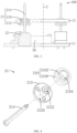
FIG. 1 is a structural schematic diagram of a vehicle-mounted radar device provided by an embodiment of the present invention; -
FIG. 2 is a structural schematic diagram of a vehicle-mounted radar adjusting device of the vehicle-mounted radar device shown inFIG. 1 ; -
FIG. 3 is a cross-sectional schematic diagram of the vehicle-mounted radar adjusting device shown inFIG. 2 ; -
FIG. 4 is an exploded schematic diagram of a movable portion of the vehicle-mounted radar adjusting device shown inFIG. 2 ; and -
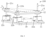
FIG. 5 is a structural schematic diagram of another state of the vehicle-mounted radar adjusting device shown inFIG. 2 . - In order to facilitate the understanding of the present invention, a more detailed explanation will be provided below in conjunction with the accompanying drawings and specific embodiments. It should be noted that when an element is referred to as being "fixed to" another element, it can be directly on another element, or one or more intermediate components can exist therebetween. When an element is referred to as being "connected to" another component, it can be directly connected to another element, or one or more intermediate components can exist therebetween. The terms "vertical", "horizontal", "left", "right", "inner", "outer", and the like are used herein for descriptive purposes only.
- Unless otherwise defined, all technical and scientific terms used in this specification have the same meanings as those commonly understood by those skilled in the technical field of the present invention. The terminology used in the description of the invention herein is for the purpose of describing particular embodiments only and is not intended to be limiting to the present invention. The term 'and/or' used herein includes any and all combinations of one or more related listed items.
- In addition, the technical features involved in the different embodiments of the present invention described below can be combined with each other as long as they do not conflict with each other.
- Referring to
FIGs. 1 and 2 together, an embodiment of the present invention provides a vehicle-mountedradar adjusting device 100 for installing a vehicle-mountedradar 200. The vehicle-mountedradar adjusting device 100 includes amounting plate assembly 10, at least oneadjusting assembly 20, and acontroller 30. Theadjusting assembly 20 and thecontroller 30 are respectively mounted to themounting plate assembly 10. Theadjusting assembly 20 and thecontroller 30 are electrically connected. - The
mounting plate assembly 10 includes afirst mounting plate 11 and asecond mounting plate 12 that are spaced apart in a vertical direction Z. A face of thefirst mounting plate 11 facing away from thesecond mounting plate 12 is mounted on a predetermined mounting position of the vehicle body. The adjustingassembly 20 and thecontroller 30 are respectively mounted on thefirst mounting plate 11. The vehicle-mountedradar 200 is provided on a face of thesecond mounting plate 12 facing away from thefirst mounting plate 11. The vehicle-mountedradar 200 is locked to thesecond mounting plate 12 by a fastener. Thesecond mounting plate 12 is connected to the adjustingassembly 20, and the adjustingassembly 20 can cause the second mountingplate 12 to rotate relative to the first mountingplate 11 about an axis in a horizontal direction, thereby adjusting the angle of the vehicle-mountedradar 200 relative to the horizontal direction. Wherein the vertical direction Z and the horizontal direction are perpendicular to each other. The vertical direction Z is a direction perpendicular to the first mountingplate 11, and the horizontal direction is a direction parallel to the first mountingplate 11. - It will be appreciated that in some implementations, the first mounting
plate 11 may also be a plane on which a predetermined mounting position of the vehicle body is located, and the drivingportion 22 and thecontroller 30 may be mounted directly on the plane on which the predetermined mounting position of the vehicle body is located. - It will be appreciated that in some embodiments, the second mounting
plate 12 may also be a housing for the vehicle-mountedradar 200. The vehicle-mountedradar 200 is directly connected to themovable portion 21. Themovable portion 21 can cause the vehicle-mountedradar 200 to rotate relative to the first mountingplate 11, thereby adjusting the angle of the vehicle-mountedradar 200. - Referring to
FIGs. 2-4 together, the adjustingassembly 20 includes amovable portion 21 and a drivingportion 22 connected to the drivingportion 22. Themovable portion 21 is connected to the second mountingplate 12. The drivingportion 22 is connected to the first mountingplate 11. The drivingportion 22 is used for driving themovable portion 21 to move relative to the second mountingplate 12 so as to cause the second mountingplate 12 to rotate about the axis in the horizontal direction. - One end of the
movable portion 21 is movably connected to the second mountingplate 12, and the other end of themovable portion 21 is connected to the drivingportion 22. Themovable portion 21 includes a rotating mechanism rotatably connected to the second mountingplate 12, and a moving mechanism having one end connected to the rotating mechanism and the other end connected to the drivingportion 22. The drivingportion 22 drives the moving mechanism to move in the vertical direction Z, and the moving mechanism rotates the second mountingplate 12 via the rotating mechanism. In this embodiment, the rotating mechanism includes auniversal ball bearing 210. The moving mechanism includes alead screw nut 212 and alead screw 214, thelead screw nut 212 connecting theuniversal ball bearing 210 and thelead screw 214, respectively. - The
universal ball bearing 210 includes anouter race 2100 and aroller 2102. The roller is rotatably provided inside theouter race 2100 and rotatable in any direction with respect to theouter race 2100. Theroller 2102 is provided with aninner bore 2104 for mounting thelead screw nut 212. Theuniversal ball bearing 210 is mounted on the second mountingplate 12. A mounting hole is provided on the second mountingplate 12, and theouter race 2100 is riveted in the mounting hole. It would be appreciated that the connection between theuniversal ball bearing 210 and the second mountingplate 12 could be provided according to practical requirements, such as welding, bonding, etc., as long as theouter race 2100 is fixed to the second mounting plate 120. - The
lead screw nut 212 is a step nut. Thelead screw nut 212 includes a large end and a small end, and astep face 2120 is provided between the large end and the small end of thelead screw nut 212. The small end of thelead screw nut 212 is riveted into theinner bore 2104 of theroller 2102, and thestep face 2120 abuts an end of theroller 2102 facing the first mountingplate 11. Thelead screw nut 212 is further provided with a threadedhole 2122 passing through thelead screw nut 212 in the vertical direction Z for connection with thelead screw 214. - The
lead screw 214 is disposed in the vertical direction X. One end of thelead screw 214 is connected to the drivingportion 22, and the other end of thelead screw 214 passes through the threadedhole 2122 of thelead screw nut 212. The surface of thelead screw 214 is provided with external threads adapted to the threadedhole 2122, and thelead screw 214 is in threaded engagement with thelead screw nut 212. Thelead screw 214 is rotatable about the vertical direction X with respect to thelead screw nut 212, thereby causing thelead screw nut 212 to move along thelead screw 214. Thelead screw nut 212 causes the second mountingplate 12 to move via theuniversal ball bearing 210. - It is to be understood that in some embodiments, the rotating mechanism may also be a universal ball, and the moving mechanism may also be a moving rod. The universal ball is connected to the moving rod. The universal ball is rotatably mounted to the second mounting
plate 12. The moving rod is connected to the drivingportion 22. The drivingportion 22 directly drives the moving rod to move. The moving rod causes the second mountingplate 12 to rotate via the universal ball. Alternatively, the rotating mechanism and the moving mechanism may be realized by other structures, which are not limited thereto. - The driving
portion 22 is fixed to the first mountingplate 11. The first mountingplate 11 is provided with a mounting groove 110. The drivingportion 22 is provided in the mounting groove 110 and locked to the first mountingplate 11 by a fastener. The drivingportion 22 is a motor powertrain. The drivingportion 22 comprises a motor and a speed reducer (not shown). The motor is connected to the speed reducer, and the speed reducer is connected to thelead screw 214 of themovable portion 21. The motor can output torque, which is reduced in speed and increased in torque through the speed reducer, and then transmitted to thescrew 214, thereby causing thescrew 214 to rotate. It can be understood that the structure of the driving portion can be set according to actual requirements, such as a rotary hydraulic cylinder, a rotary pneumatic cylinder, etc. and only needs to be able to cause the rotation of thelead screw 214. - It is to be understood that in some embodiments, the driving
portion 22 may also be a linear motor, a linear hydraulic cylinder, a linear pneumatic cylinder, etc. The drivingportion 22 drives the moving mechanism of themovable portion 21 to make a linear movement, thereby causing the rotation of the second mountingplate 12. - Referring to
FIG. 5 together, it should be noted that the number of the adjustingassemblies 20 is determined according to the shape of the second mountingplate 12. The number of the adjustingassemblies 20 is the same as the number of corners included in the shape of the second mountingplate 12, and at least one of the adjustingassemblies 20 is provided on each corner of one face of the second mountingplate 12. Wherein at least one side of the second mountingplate 12 is provided with the adjustingassembly 20. Furthermore, at least two adjustingassemblies 20 are provided on one side of the second mountingplate 12, and an axis in a horizontal direction is formed between the at least two adjustingassemblies 20. Wherein the horizontal direction is perpendicular to the vertical direction Z. - In the present embodiment, taking the shape of the second mounting
plate 12 as a triangle as an example, the number of the adjustingassemblies 20 is three, and threeadjusting assemblies 20 are respectively provided at three corners of the second mountingplate 12. The connection lines between the threeadjusting assemblies 20 form three axes in the horizontal direction. The three axes in the horizontal direction include a first horizontal axis and a second horizontal axis which are perpendicular to each other. The threeadjusting assemblies 20 respectively cause the second mountingplate 12 to rotate about the first horizontal axis and the second horizontal axis so as to adjust the angle of the vehicle-mountedradar 200 relative to the horizontal direction. Three of the adjustingassemblies 20 are respectively connected between the first and second mountingplates adjusting assemblies 20 are respectively electrically connected to thecontroller 30. - Specifically, each of the three
adjusting assemblies 20 includes amovable portion 21 and a drivingportion 22, respectively. The threemovable portions 21 are the firstmovable portion 21a, the secondmovable portion 21b, and the thirdmovable portion 21c respectively. The three drivingportions 22 are thefirst driving portion 22a, thesecond driving portion 22b, and thethird driving portion 22c, respectively. Thefirst driving portion 22a is connected to the firstmovable portion 21a, thesecond driving portion 22b is connected to the secondmovable portion 21b, and thethird driving portion 22c is connected to the thirdmovable portion 21c. - Each of the first
movable portion 21a, the secondmovable portion 21b, and the thirdmovable portion 21c includes the rotating mechanism and the moving mechanism. The first and secondmovable portions plate 12 in the first horizontal direction X, and the second and thirdmovable portions plate 12 in the second horizontal direction Y. The connection line between the first and secondmovable portions movable portions plate 12 to rotate about the first horizontal axis to adjust the horizontal angle of the vehicle-mountedradar 200. The connection line between the second and thirdmovable portions movable portions plate 12 to rotate about the second horizontal axis to adjust another horizontal angle of the vehicle-mountedradar 200. Wherein the first horizontal direction X and the second horizontal direction Y are perpendicular to each other. The first horizontal direction X and the second horizontal direction Y are perpendicular to the vertical direction Z, respectively. - The
first driving portion 22a, thesecond driving portion 22b, and thethird driving portion 22c are respectively mounted to the first mountingplate 11. Wherein thefirst driving portion 22a is used for driving the firstmovable portion 21a, thesecond driving portion 22b is used for driving the secondmovable portion 21b, and thethird driving portion 22c is used for driving the thirdmovable portion 21c. - When the vehicle-mounted
radar 200 needs to adjust an angle, the first andsecond driving portions movable portions lead screw nuts 212 of the firstmovable portion 21a and thelead screw nut 212 of the secondmovable portion 21b to ascend or descend at the same time. Theroller 2102 of the firstmovable portion 21a and theroller 2102 of the secondmovable portion 21b cause one end of the second mountingplate 12 which faces away from the thirdmovable portion 21c to ascend or descend, and theouter race 2100 of eachmovable portion 21 causes the second mountingplate 12 to rotate relative to eachroller 2102 so that the second mountingplate 12 rotates about the first horizontal axis. Alternatively, thesecond driving portion 22b and thethird driving portion 22c are started at the same time, drive thelead screw 214 of the secondmovable portion 21b and thelead screw 214 of the thirdmovable portion 21c rotate forward or reverse at the same time, and cause thelead screw nut 212 of the secondmovable portion 21b and thelead screw nut 212 of the thirdmovable portion 21c to ascend or descend at the same time. Theroller 2102 of the secondmovable portion 21b and theroller 2102 of the thirdmovable portion 21c cause the second mountingplate 12 to ascend or descend away from one end of the firstmovable portion 21a, and theouter race 2100 of eachmovable portion 21 causes the second mountingplate 12 to rotate relative to eachroller 2102 so that the second mountingplate 12 rotates about the second horizontal axis. The angle of the vehicle-mountedradar 200 with respect to the horizontal direction is adjusted by adjusting the second mountingplate 12 to rotate with respect to the first horizontal axis and the second horizontal axis, respectively. Wherein the forward rotation turns counterclockwise or clockwise about the vertical direction X, and the reverse rotation direction is opposite to the forward rotation direction. - Further, a line between three of the adjusting
assemblies 20 forms three horizontal axes, and further includes a third horizontal axis formed by a line between the first and thirdmovable portions first driving portion 22a and thethird driving portion 22c are started at the same time, and drive the first and thirdmovable portions plate 12 to rotate about the third horizontal axis so as to further adjust the angle of the vehicle-mountedradar 200 relative to the horizontal direction. - In some other embodiments, the shape of the second mounting plate can be set according to actual requirements, and the number of the adjusting assemblies can also be adjusted accordingly. For example, the second mounting plate is provided as a rectangle, and the number of the adjusting assemblies is correspondingly provided as four. Four of the adjusting assemblies are respectively provided at four corners of the second mounting plate, and connecting lines between four of the adjusting assemblies form at least four axes in the horizontal direction so that the second mounting plate can rotate about at least four axes in the horizontal direction respectively. Alternatively, the second mounting plate is provided as a pentagon, hexagon, etc. and the number of the adjusting assemblies is correspondingly set to five, six, etc. to adjust the plurality of horizontal angles of the second mounting plate.
- In some other embodiments, the number of adjusting
assemblies 20 may also be greater than the number of corners included in the shape of the second mountingplate 12, such that at least two of the adjustingassemblies 20 are provided on one side of the second mountingplate 12. For example, when the second mounting plate is triangular, the number of the adjusting assemblies may be four. Three of the adjusting assemblies are respectively arranged at three corners of the second mounting plate. The connection lines between the three of the adjusting assemblies respectively form three horizontal axes. The other one of the adjusting assemblies is arranged between two adjusting assemblies arranged along one of the horizontal axes. The four adjusting assemblies respectively cause the second mounting plate to rotate about the three horizontal axes, thereby adjusting the angle of the vehicle-mounted radar with respect to the horizontal direction. - In some other embodiments, the number of adjusting
assemblies 20 may not correspond to the shape of the second mountingplate 12, e.g. the second mountingplate 12 may be provided as a circle, oval, etc. The number of adjustingassemblies 20 may be provided as at least two. The number of adjustingassemblies 20 is determined according to the number of rotational axes required for the second mountingplate 12. For example, when the second mounting plate only needs to rotate about one axis in the horizontal direction, the number of the adjusting assemblies may be at least two. At least two adjusting assemblies are respectively arranged on the second mounting plate in a first horizontal direction. A connecting line between at least two of the adjusting assemblies forms an axis of rotation in the first horizontal direction. One end of the second mounting plate facing away from at least two of the adjusting assemblies in the second horizontal direction is rotatably connected to the first mounting plate or the vehicle body. At least two of the adjusting assemblies ascend or descend at the same time, thereby causing the second mounting plate to rotate along a rotation axis in a first horizontal direction. Alternatively, the number of the adjusting assemblies can be set according to other practical requirements and only needs to be able to meet the angle adjustment requirements of the vehicle-mounted radar, which is not limited herein. - The
controller 30 is mounted on the first mountingplate 11, and thecontroller 30 is locked to the first mountingplate 11 by a fastener. Thecontroller 30 is electrically connected to thefirst driving portion 22a, thesecond driving portion 22b, and thethird driving portion 22c, respectively. Thecontroller 30 is used for controlling thefirst driving portion 22a, thesecond driving portion 22b, and thethird driving portion 22c to start or stop, respectively. For example, thecontroller 30 may control the first andsecond driving portions movable portions controller 30 may control the second and thethird driving portions movable portions controller 30 may control the first andthird driving portions movable portions controller 30 may control the start of one of the first, second, andthird driving portions movable portions - In some embodiments, the vehicle-mounted
radar adjusting device 100 further includes an angle sensor (not shown in the figures) electrically connected to the controller for detecting radar angle change information and transmitting it to thecontroller 30. The angle sensor may be provided in the vehicle-mountedradar 200, or the angle sensor may be provided on a certain face of the vehicle-mountedradar 200, or the angle sensor may be provided on the vehicle body. When the vehicle body is loaded, turned, uphill, or the like, the vehicle body is tilted, causing the vehicle-mountedradar 200 to follow the vehicle body to tilt so that the angle of the vehicle-mountedradar 200 in the horizontal direction changes with respect to a preset angle thereof. Wherein the radar angle change information is an angle change value of the vehicle-mountedradar 200. - The
controller 30 determines whether the angle of the vehicle-mountedradar 200 needs to be adjusted after processing the radar angle change information detected by the angle sensor. When thecontroller 30 determines that it is necessary to adjust the angle of the vehicle-mountedradar 200, it further determines the adjustment value of the angle of the vehicle-mountedradar 200 that needs to be adjusted. Thecontroller 30 controls the drivingportion 22 to be started or stopped according to the value required to adjust the angle of the vehicle-mountedradar 200, so that themovable portion 21 causes the second mounting plate to rotate to the adjustment value, thereby adjusting the inclination angle of the vehicle-mountedradar 200 with respect to the horizontal direction, and ensuring the accuracy of the mounting angle of the vehicle-mountedradar 200. The adjustment value is an angular value of rotation of the second mounting plate about the axis in the horizontal direction. - In some embodiments, when rotation of the second mounting plate about the axis in the horizontal direction requires cooperation of at least two of the adjusting
assemblies 20, thecontroller 30 may send synchronization control commands to the driving portions of at least two of the adjustingassemblies 20 to cause synchronize rotation of the movable portions of at least two of the adjustingassemblies 20. - Specifically, after the
controller 30 determines that the adjustment value of the angle of the vehicle-mountedradar 200 needs to be adjusted, thecontroller 30 controls the first andsecond driving portions movable portions plate 12 to rotate about the first horizontal axis; and/or thecontroller 30 controls thesecond driving portion 22b and thethird driving portion 22c to start synchronously according to the adjustment value so as to drive the second and thirdmovable portions plate 12 to rotate about the second horizontal axis. Wherein the adjustment value includes a value of an angle of rotation of the second mounting plate about the first horizontal axis and a value of an angle of rotation about the second horizontal axis. - In some embodiments, the
controller 30 may also control the synchronous start of the first andthird driving portions movable portions plate 12 to rotate about a third horizontal axis. Wherein the adjustment value further includes an angular value of the rotation of the second mounting plate about the third horizontal axis. - Note that "electrically connected" in this embodiment means the communication of electrical signals between the two structures can be either a wired electrical connection via a cable or a radio connection via Bluetooth, WIFI modules, etc.
- Referring back to
FIG. 1 , another embodiment of the present invention provides a vehicle-mountedradar device 300 including the vehicle-mountedradar adjusting device 100 according to any one of the above embodiments, and a vehicle-mountedradar 200 mounted to the vehicle-mountedradar adjusting device 100. The vehicle-mountedradar adjusting device 100 is used for adjusting the inclination angle of the vehicle-mountedradar 200. - In the present embodiment, the vehicle-mounted
radar 200 uses a millimeter wave radar. The vehicle-mountedradar 200 is used for transmitting and receiving millimeter waves (millimeter electromagnetic waves) reflected by an obstacle, obtaining physical environment information (such as a relative distance, a relative speed, an angle, a movement direction, etc. between the vehicle body and other objects) around the vehicle body after processing, and providing an information condition for a vehicle body control system. The vehicle control system takes corresponding active safety measures or intervenes based on the feedback information from theradar body 20, ensuring safety and comfort during the driving process and reducing the probability of accidents. It will be appreciated that in some other embodiments, the vehicle-mountedradar 200 may also be an ultrasonic radar, a laser radar, or the like. - Finally, it should be noted that the above embodiments are only used to illustrate the technical solution of the present invention and not to limit it. Combinations of features in the above embodiments or in different embodiments are also possible within the spirit of the invention, the steps can be implemented in any order, and there are many other variations of the different aspects of the invention described above, which are not provided in detail for the sake of brevity. Although the present invention has been described in detail with reference to the foregoing embodiments, those skilled in the art will appreciate that: the technical solutions disclosed in the above-mentioned embodiments can still be amended, or some of the technical features thereof can be replaced by equivalents. Such modifications and substitutions do not depart from the spirit and scope of the embodiments of the present invention.
Claims (17)
- A vehicle-mounted radar adjusting device, characterized by comprising:a first mounting plate configured to be mounted to a vehicle body;a second mounting plate spaced apart from the first mounting plate in a vertical direction, the second mounting plate being used for installing the vehicle-mounted radar, and the vertical direction referring to a direction perpendicular to the first mounting plate;at least one adjusting assembly, the adjusting assembly being respectively connected to the first mounting plate and the second mounting plate, the adjusting assembly being movably connected to the second mounting plate, the adjusting assembly being able to cause the second mounting plate to rotate about an axis in a horizontal direction so as to adjust a pitch angle of the second mounting plate relative to the first mounting plate; wherein the horizontal direction refers to a direction parallel to a plane in which the first mounting plate is located; anda controller, the controller being mounted to the first mounting plate, the controller being electrically connected to the adjusting assembly, the controller being used for controlling the adjusting assembly to cause the second mounting plate to rotate about the axis in the horizontal direction.
- The vehicle-mounted radar adjusting device according to claim 1, characterized in that, the number of the adjusting assemblies is determined by the shape of the second mounting plate.
- The vehicle-mounted radar adjusting device according to claim 2, characterized in that, the number of the adjusting assemblies is the same as the number of corners included in the shape of the second mounting plate, and the adjusting assemblies are respectively provided on corners of one face of the second mounting plate.
- The vehicle-mounted radar adjusting device according to claim 2, characterized in that, at least one side of the second mounting plate is provided with the adjusting assembly.
- The vehicle-mounted radar adjusting device according to claim 4, characterized in that, at least two of the adjusting assemblies are provided on one side of the second mounting plate, and a connecting line between the at least two adjusting assemblies forms an axis in the horizontal direction.
- The vehicle-mounted radar adjusting device according to any one of claims 1-5, characterized in that, the adjusting assembly comprises a driving portion and movable portions, the driving portion being connected to the first mounting plate, the movable portion being connected to the second mounting plate, the driving portion being used for moving the movable portion relative to the second mounting plate to cause the second mounting plate to rotate about the axis in the horizontal direction.
- The vehicle-mounted radar adjusting device according to claim 6, characterized in that, the movable portion includes a rotating mechanism and a moving mechanism, the moving mechanism being connected to the rotating mechanism;the rotating mechanism is further rotatably connected to the second mounting plate, and the moving mechanism is further connected to the driving portion; andthe driving portion drives the moving mechanism to move in a vertical direction, and causes the second mounting plate to rotate via the rotating mechanism.
- The vehicle-mounted radar adjusting device according to claim 7, characterized in that, the rotating mechanism comprises a universal ball bearing mounted to the second mounting plate.
- The vehicle-mounted radar adjusting device according to claim 7, characterized in that, the universal ball bearing comprises an outer race and a roller rotatably provided inside the outer race; and
the outer race is connected to the second mounting plate and the roller is connected to the moving mechanism. - The vehicle-mounted radar adjusting device according to claim 7, characterized in that, the moving mechanism comprises a lead screw nut and a lead screw sleeved on the lead screw;the lead screw nut is connected to the rotating mechanism, and the lead screw is connected to the driving portion; andthe driving portion may drive the lead screw to rotate and cause the lead screw nut to move in the vertical direction.
- The vehicle-mounted radar adjusting device according to claim 7, characterized in that, the driving portion is a motor powertrain.
- The vehicle-mounted radar adjusting device according to claim 1, characterized by further comprising an angle sensor electrically connected to the controller; and
the angle sensor is configured to detect radar angle change information and transmit the information to the controller. - The vehicle-mounted radar adjusting device according to claim 12, characterized in that, the angle sensor is provided in the vehicle-mounted radar or on a certain face of the vehicle-mounted radar.
- The vehicle-mounted radar adjusting device according to claim 12, characterized in that, the controller is configured to determine whether the angle of the vehicle-mounted radar needs to be adjusted after processing the radar angle change information detected by the angle sensor.
- The vehicle-mounted radar adjusting device according to claim 14, characterized in that, the controller is further used for further determining an adjustment value of the angle of the vehicle-mounted radar to be adjusted when the angle of the vehicle-mounted radar needs to be adjusted, and controlling the adjusting assembly to cause the second mounting plate to rotate to the adjustment value;
wherein the adjustment value is an angle of rotation of the second mounting plate about the axis in the horizontal direction. - A vehicle-mounted radar device, characterized by comprising:a vehicle-mounted radar;the vehicle-mounted radar adjusting device according to any one of claims 1-15, the vehicle-mounted radar being mounted on a face of the second mounting plate facing away from the first mounting plate.
- The vehicle-mounted radar adjusting device according to claim 16, characterized in that, the radar is locked to the second mounting plate through a fastener.
Applications Claiming Priority (2)
| Application Number | Priority Date | Filing Date | Title |
|---|---|---|---|
| CN202110372134.6A CN113147608A (en) | 2021-04-07 | 2021-04-07 | Vehicle-mounted radar adjusting device and vehicle-mounted radar device |
| PCT/CN2022/081405 WO2022213786A1 (en) | 2021-04-07 | 2022-03-17 | Vehicle-mounted radar adjusting device and vehicle-mounted radar device |
Publications (2)
| Publication Number | Publication Date |
|---|---|
| EP4299382A1 true EP4299382A1 (en) | 2024-01-03 |
| EP4299382A4 EP4299382A4 (en) | 2024-08-14 |
Family
ID=76888561
Family Applications (1)
| Application Number | Title | Priority Date | Filing Date |
|---|---|---|---|
| EP22783855.4A Withdrawn EP4299382A4 (en) | 2021-04-07 | 2022-03-17 | VEHICLE MOUNTED RADAR ADJUSTMENT DEVICE AND VEHICLE MOUNTED RADAR DEVICE |
Country Status (4)
| Country | Link |
|---|---|
| US (1) | US20240157889A1 (en) |
| EP (1) | EP4299382A4 (en) |
| CN (1) | CN113147608A (en) |
| WO (1) | WO2022213786A1 (en) |
Families Citing this family (4)
| Publication number | Priority date | Publication date | Assignee | Title |
|---|---|---|---|---|
| CN113147608A (en) * | 2021-04-07 | 2021-07-23 | 深圳市道通科技股份有限公司 | Vehicle-mounted radar adjusting device and vehicle-mounted radar device |
| CN118387002A (en) * | 2023-01-30 | 2024-07-26 | 比亚迪股份有限公司 | Adjusting device of vehicle-mounted screen, vehicle-mounted screen assembly and vehicle |
| DE102023106750A1 (en) * | 2023-03-17 | 2024-09-19 | Sick Ag | Aligned sensor |
| CN120370274B (en) * | 2025-06-27 | 2026-05-08 | 江西省天驰高速科技发展有限公司 | Radar checking device and method based on double leveling mechanisms |
Family Cites Families (23)
| Publication number | Priority date | Publication date | Assignee | Title |
|---|---|---|---|---|
| DE19949969A1 (en) * | 1999-10-16 | 2001-04-19 | Volkswagen Ag | Fixing for car separation sensor has ball joint allows two axis adjustment |
| DE10025501C2 (en) * | 2000-05-23 | 2002-05-02 | Bosch Gmbh Robert | Control arrangement for an adjustable housing |
| DE10154080A1 (en) * | 2001-11-02 | 2003-05-15 | Bosch Gmbh Robert | Bracket for an adjustable housing |
| JP3730956B2 (en) * | 2002-12-11 | 2006-01-05 | 本田技研工業株式会社 | Axis adjusting device for transmitter / receiver for moving body |
| JP2007038806A (en) * | 2005-08-02 | 2007-02-15 | Nissan Motor Co Ltd | Electrical component protection structure |
| JP2010002272A (en) * | 2008-06-19 | 2010-01-07 | Toyota Motor Corp | Axis adjustment method and axis adjustment device for radar device |
| DE102011119392A1 (en) * | 2011-11-24 | 2013-05-29 | Knorr-Bremse Systeme für Nutzfahrzeuge GmbH | Adjustable mounting device for sensors |
| US10323936B2 (en) * | 2016-12-30 | 2019-06-18 | Bosch Automotive Service Solutions Inc. | Calibration system for sensors and cameras on vehicles |
| CN107804237A (en) * | 2017-10-26 | 2018-03-16 | 四川嘉义雷科电子技术有限公司 | Beneficial to the automobile collision avoidance radar of installation |
| DE212018000382U1 (en) * | 2017-12-25 | 2020-07-28 | Autel Intelligent Technology Corp., Ltd | Vehicle mounted radar calibration device |
| CN108454584B (en) * | 2018-04-20 | 2024-08-27 | 深圳市道通科技股份有限公司 | Automobile calibration equipment |
| CN208283553U (en) * | 2018-05-29 | 2018-12-25 | 惠州市德赛西威汽车电子股份有限公司 | A kind of vehicle-mounted millimeter wave radar installation adjusting device |
| CN108859986A (en) * | 2018-06-29 | 2018-11-23 | 滁州市经纬装备科技有限公司 | A kind of radar adjusting bracket |
| CN210129117U (en) * | 2019-02-01 | 2020-03-06 | 深圳市道通科技股份有限公司 | Calibration system and calibration support thereof |
| CN110927701B (en) * | 2019-11-07 | 2022-04-15 | 深圳市优必选科技股份有限公司 | Radar leveling device |
| CN111422140A (en) * | 2020-04-24 | 2020-07-17 | 新余国科特种装备有限公司 | A vehicle-mounted automatic leveling platform for weather radar |
| CN111665478A (en) * | 2020-05-26 | 2020-09-15 | 奇瑞商用车(安徽)有限公司 | Automobile radar sensor adjusting support structure |
| CN111717124B (en) * | 2020-06-05 | 2021-11-23 | 北京超星未来科技有限公司 | Angle adjusting device of adjustable laser radar angle |
| CN212781209U (en) * | 2020-07-31 | 2021-03-23 | 无锡威孚高科技集团股份有限公司 | Radar adjusting device and device for mounting, calibrating and verifying vehicle-mounted radar |
| CN215116790U (en) * | 2021-03-04 | 2021-12-10 | 深圳市道通智能汽车有限公司 | A radar and early warning system |
| CN215097329U (en) * | 2021-04-07 | 2021-12-10 | 深圳市道通科技股份有限公司 | Vehicle-mounted radar adjusting device and vehicle-mounted radar device |
| CN113147608A (en) * | 2021-04-07 | 2021-07-23 | 深圳市道通科技股份有限公司 | Vehicle-mounted radar adjusting device and vehicle-mounted radar device |
| US11933911B2 (en) * | 2021-08-19 | 2024-03-19 | Aptiv Technologies AG | Radar system calibration with bistatic sidelobe compensation |
-
2021
- 2021-04-07 CN CN202110372134.6A patent/CN113147608A/en active Pending
-
2022
- 2022-03-17 EP EP22783855.4A patent/EP4299382A4/en not_active Withdrawn
- 2022-03-17 US US18/552,672 patent/US20240157889A1/en active Pending
- 2022-03-17 WO PCT/CN2022/081405 patent/WO2022213786A1/en not_active Ceased
Also Published As
| Publication number | Publication date |
|---|---|
| WO2022213786A1 (en) | 2022-10-13 |
| US20240157889A1 (en) | 2024-05-16 |
| EP4299382A4 (en) | 2024-08-14 |
| CN113147608A (en) | 2021-07-23 |
Similar Documents
| Publication | Publication Date | Title |
|---|---|---|
| US20240157889A1 (en) | Vehicle-mounted radar adjusting device and vehicle-mounted radar device | |
| CN112683112B (en) | Optical platform and radar co-frame turntable system | |
| CN112653367B (en) | Control system and method for common rotating table | |
| US10490886B2 (en) | Mount | |
| US10677893B2 (en) | Vertical alignment device and method for vehicle radar | |
| EP1472109B1 (en) | A drive unit, and a powered vehicle | |
| US11092219B2 (en) | Linear motion system | |
| WO2017201890A1 (en) | Servo rotary scanning system of three-dimensional holographic imaging | |
| EP4578730A1 (en) | Cantilever shaft assembly and carrying and feeding vehicle | |
| CN215097329U (en) | Vehicle-mounted radar adjusting device and vehicle-mounted radar device | |
| WO2011048831A1 (en) | Obstacle detection device for vehicle | |
| CN214703972U (en) | Laser radar support | |
| CN209198946U (en) | Sensor position adjusts apparatus and system, vehicle navigation apparatus and system, vehicle | |
| CN112319387B (en) | Stay wire control type following stable platform | |
| KR20200052390A (en) | Distance measuring equipment for autonomous vehicles | |
| US4953422A (en) | Compound angle limiting device | |
| CN118288328B (en) | Scene adaptive robot self-adjusting wrist joint and control method thereof | |
| KR102426922B1 (en) | Distance measuring equipment for autonomous vehicles | |
| CN213619612U (en) | Photoelectric follow-up platform | |
| WO2022204909A1 (en) | Microwave radar and mobile platform | |
| CN220948510U (en) | Longitudinal electric propulsion lock | |
| CN224203412U (en) | Millimeter wave radar assembly | |
| CN222479901U (en) | Monitoring system | |
| CN220465774U (en) | Compact electric steering engine transmission mechanism | |
| EP4620808A1 (en) | Sensor interface for control of an aircraft flight control surface |
Legal Events
| Date | Code | Title | Description |
|---|---|---|---|
| STAA | Information on the status of an ep patent application or granted ep patent |
Free format text: STATUS: THE INTERNATIONAL PUBLICATION HAS BEEN MADE |
|
| PUAI | Public reference made under article 153(3) epc to a published international application that has entered the european phase |
Free format text: ORIGINAL CODE: 0009012 |
|
| STAA | Information on the status of an ep patent application or granted ep patent |
Free format text: STATUS: REQUEST FOR EXAMINATION WAS MADE |
|
| 17P | Request for examination filed |
Effective date: 20230926 |
|
| AK | Designated contracting states |
Kind code of ref document: A1 Designated state(s): AL AT BE BG CH CY CZ DE DK EE ES FI FR GB GR HR HU IE IS IT LI LT LU LV MC MK MT NL NO PL PT RO RS SE SI SK SM TR |
|
| RAP3 | Party data changed (applicant data changed or rights of an application transferred) |
Owner name: AUTEL INTELLIGENT TECHNOLOGY CORP. LTD. |
|
| REG | Reference to a national code |
Ref country code: DE Ref legal event code: R079 Free format text: PREVIOUS MAIN CLASS: B60R0011000000 Ipc: G01S0007020000 |
|
| DAV | Request for validation of the european patent (deleted) | ||
| DAX | Request for extension of the european patent (deleted) | ||
| A4 | Supplementary search report drawn up and despatched |
Effective date: 20240715 |
|
| RIC1 | Information provided on ipc code assigned before grant |
Ipc: G01S 15/931 20200101ALN20240709BHEP Ipc: G01S 7/521 20060101ALN20240709BHEP Ipc: G01S 7/52 20060101ALN20240709BHEP Ipc: G01S 7/497 20060101ALN20240709BHEP Ipc: G01S 7/481 20060101ALN20240709BHEP Ipc: G01S 7/40 20060101ALN20240709BHEP Ipc: G01S 13/931 20200101ALI20240709BHEP Ipc: G01S 7/02 20060101AFI20240709BHEP |
|
| STAA | Information on the status of an ep patent application or granted ep patent |
Free format text: STATUS: THE APPLICATION IS DEEMED TO BE WITHDRAWN |
|
| 18D | Application deemed to be withdrawn |
Effective date: 20250204 |