EP4298980B1 - Wärmepumpengeschirrspüler - Google Patents
Wärmepumpengeschirrspüler Download PDFInfo
- Publication number
- EP4298980B1 EP4298980B1 EP23176352.5A EP23176352A EP4298980B1 EP 4298980 B1 EP4298980 B1 EP 4298980B1 EP 23176352 A EP23176352 A EP 23176352A EP 4298980 B1 EP4298980 B1 EP 4298980B1
- Authority
- EP
- European Patent Office
- Prior art keywords
- dishwasher
- hose
- inlet
- rear wall
- fixing member
- Prior art date
- Legal status (The legal status is an assumption and is not a legal conclusion. Google has not performed a legal analysis and makes no representation as to the accuracy of the status listed.)
- Active
Links
Images


Classifications
-
- A—HUMAN NECESSITIES
- A47—FURNITURE; DOMESTIC ARTICLES OR APPLIANCES; COFFEE MILLS; SPICE MILLS; SUCTION CLEANERS IN GENERAL
- A47L—DOMESTIC WASHING OR CLEANING; SUCTION CLEANERS IN GENERAL
- A47L15/00—Washing or rinsing machines for crockery or tableware
- A47L15/42—Details
- A47L15/4291—Recovery arrangements, e.g. for the recovery of energy or water
-
- A—HUMAN NECESSITIES
- A47—FURNITURE; DOMESTIC ARTICLES OR APPLIANCES; COFFEE MILLS; SPICE MILLS; SUCTION CLEANERS IN GENERAL
- A47L—DOMESTIC WASHING OR CLEANING; SUCTION CLEANERS IN GENERAL
- A47L15/00—Washing or rinsing machines for crockery or tableware
- A47L15/42—Details
- A47L15/4251—Details of the casing
Definitions
- the present invention relates to a heat pump dishwasher wherein the exhaust air is effectively discharged.
- the use of hot water for the washing process improves the washing performance.
- the heating of the washing water is performed by means of a heater.
- the washing water is heated by using the heat pump system. In this case, energy saving is provided compared to conventional dishwashers.
- the basic components of the heat pump system are compressor, evaporator, condenser, capillary tube and fan.
- the compressor pressurizes the refrigerant fluid and directs the same to the condenser.
- the condenser condenses the refrigerant fluid and heats the water which is in direct contact with the condenser.
- the refrigerant fluid enters the capillary tube. While passing through the capillary tube, the refrigerant fluid loses pressure, expands and enters the evaporator. While passing through the evaporator pipes, the refrigerant fluid draws heat from the ambient air directed thereon, evaporates and cools the surrounding air. The cooled air is blown out of the dishwasher after the evaporator.
- the ambient air is sucked by means of a fan and passed over the evaporator.
- the ambient heat is drawn onto the heat pump and used to heat the water.
- the air is discharged from the cabinet opening to the environment. This opening is provided on the left or right side of the dishwasher.
- the water intake hose outlet and the water discharge hose outlet of the dishwasher are provided on the left or right side of the dishwasher rear wall. Said hoses move between the rear wall of the dishwasher and the cabinet and come out of the opening.
- German Patent Application No. DE102019100004 the formation of an air flow path is disclosed, by means of a sealing member which is provided on the air outlet between a heat pump dishwasher and the cabinet, which is provided between the rear wall of the dishwasher and the wall of the cabinet.
- a dishwasher comprising a base, and a fan and an evaporator provided an air duct extending from said base.
- the air duct extends from the front of the dishwasher to the back thereof and an air opening is provided at the back side.
- EP2777474 Another state of the art embodiment is disclosed in the European Patent No. EP2777474 .
- a heat pump dishwasher is disclosed, wherein the air sucked through the air inlet is guided towards the evaporator by passing through an opening with guiding surfaces and a dust holder.
- the aim of the present invention is the realization of a heat pump dishwasher wherein the exhaust air is effectively discharged.
- the dishwasher realized in order to attain the aim of the present invention, explicated in the first claim and the respective claims thereof, is a heat pump dishwasher, and comprises a washing tub; an evaporator; a rear wall; an opening which aligns with the part of the rear wall whereon the evaporator is disposed; a water inlet hose; a water discharge hose; and at least one hose holder for each of the water inlet and discharge hoses, fixed onto the rear wall and enabling the water inlet and discharge hoses onto the rear wall such that the opening remains between the water inlet hose and the water discharge hose.
- the water inlet and discharge hoses are prevented from covering the opening, creating an obstacle in front of the opening and decreasing the air passage cross-sectional area of the opening.
- the flow rate of the air discharged out of the dishwasher is prevented from being adversely affected, and the efficiency of the heat pump, hence of the dishwasher is increased.
- the dishwasher comprises two channels as the hose holder which are arranged above and below the opening such that the opening remains therebetween, which extend parallel to each other along the rear wall, such that one receives the water inlet hose and the other receives the discharge hose.
- the dishwasher comprises at least one fixing member in the form of a clamp which passes over the hose in the channel and which is fixed with fixing elements to the rear wall so as to prevent the hose placed in the channel from being detached from the channel.
- the fixing member is flat.
- the hose is entirely embedded into the channel.
- the fixing member is fixed to the rear wall from two ends thereof such that the hose placed into the channel remains therebetween.
- the fixing member is fixed to the rear wall from a single end thereof while the other end has a jointed structure so as to rotate around the end fixed to the rear wall.
- the dishwasher comprises hook-and-loop fasteners as the hose holder.
- one surface of the hook-and-loop fasteners is fixed to the rear wall such that the hose remains therebetween, and after the hose is placed onto the rear wall, the other surface of the hook-and-loop fasteners is brought onto the first surface over the hose to fix the same.
- the water inlet and discharge hoses are positioned efficiently so as not to block the air outlet such that the air leaving the evaporator has a high flow rate. Since there is no obstacle in front of the cold exhaust air to prevent the same from being discharged through the air outlet, unwanted cooling in the dishwasher is avoided and the efficiency of the heat pump is increased by preventing the drying performance from being adversely affected. Thus, the washing time of the dishwasher is decreased.
- FIG. 6-8 A dishwasher realized in order to attain the aim of the present invention is illustrated in the attached figures, with figures 6-8 showing an embodiment of a dishwasher according to the invention, and figures 1-5 and 9 showing examples useful for understanding the present invention, where:
- the dishwasher (1) of the present invention is a heat pump dishwasher (1), and comprises a washing tub; an evaporator; a rear wall (2); an opening (3) which aligns with the part of the rear wall (2) whereon the evaporator is disposed; an inlet hose (4); a discharge hose (5); and at least one hose holder (6) for each of the inlet and discharge hoses (4 and 5), fixed onto the rear wall (2) and enabling the inlet and discharge hoses (4 and 5) onto the rear wall (2) such that the opening (3) remains between the inlet hose and the discharge hose (4 and 5).
- the inlet and discharge hoses (4 and 5) are prevented from covering the opening (3), creating an obstacle in front of the opening (3) and decreasing the air passage cross-sectional area of the opening (3).
- the flow rate of the air discharged out of the dishwasher (1) is prevented from being adversely affected, and the efficiency of the heat pump, hence of the dishwasher (1) is increased.
- the dishwasher (1) comprises the C-shaped hose holder (6), wherein the hose holder (6) comprises an orifice (7) through which the inlet and discharge hoses (4 and 5) pass, a housing (8) wherein the inlet and discharge hoses (4 and 5) are fitted after passing through the orifice (7), and a base (9) which is positioned outside the housing (8) and which enables the hose holder (6) to be fixed to the rear wall (2).
- the inlet and discharge hoses (4 and 5) are passed through the orifice (7) to be fitted into the housing (8) in the hose holder (6) fixed to the rear wall (2) of the dishwasher (1) by means of the base (9).
- the inlet and discharge hoses (4 and 5) pass through the orifice (7), the two opposite edges of the orifice (7) are stretched, and by means of this stretching, the inlet and discharge hoses (4 and 5) are easily fitted into the housing (8).
- the orifice (7) moves back and returns to the initial position, and the inlet and discharge hoses (4 and 5) fitted into the housing (8) are prevented from being detached from the housing (8) by themselves.
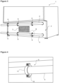
- the dishwasher (1) comprises at least two, preferably three hose holders (6) for each of the inlet hose (4) and the discharge hose (5) on the same line, enabling the inlet and discharge hoses (4 and 5) to extend parallel to each other at the top and bottom of the opening (3) ( Figure 1 and Figure 2 ).
- the hose holder (6) comprises a clamp-shaped step (10) which is fixed to the rear wall (2) and which supports the inlet and discharge hoses (4 and 5) from bottom, and a holder (11) which is disposed onto the step (10) and which covers the inlet and discharge hoses (4 and 5) from above to be fixed to the step (10) ( Figure 3 and Figure 4 ).
- the hose holder (6) comprises two channels (12) which are arranged above and below the opening (3) such that the opening (3) remains therebetween, which extend parallel to each other along the rear wall (2), such that one receives the inlet hose (4) and the other receives the discharge hose (5).
- the dishwasher (1) comprises at least one fixing member (13) preferably in the form of a clamp which passes over the inlet and discharge hoses (4 and 5) in the channel (12) and which is fixed with fixing elements to the rear wall (2) so as to prevent the inlet and discharge hoses (4 and 5) placed in the channel (12) from being detached from the channel (12) ( Figure 5 ).
- the fixing member (13) is flat and in the form of a plate.
- the inlet and discharge hoses (4 and 5) are completely embedded into the channel (12).
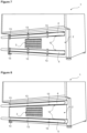
- the fixing member (13) is fixed to the rear wall (2) from two ends thereof such that the inlet and discharge hoses (4 and 5) placed into the channel (12) remain therebetween ( Figure 6 ).
- the fixing member (13) is fixed to the rear wall (2) from a single end thereof while the other end has a jointed structure so as to rotate around the end fixed to the rear wall (2).
- the inlet and discharge hoses (4 and 5) can be quickly and easily fitted into the channel (12) and detached from the channel (12).
- the dishwasher (1) in order to enable the inlet and discharge hoses (4 and 5) to be properly fitted into the channel (12) and prevent the same from being detached from the channel (12) unintentionally, the dishwasher (1) comprises the C-shaped fixing member (13) disposed in the channel (12) ( Figure 8 ).
- the hose holder (6) comprises hook-and-loop fasteners, wherein one surface of the hook-and-loop fasteners is fixed to the rear wall (2), the other surface is passed over the inlet and discharge hoses (4 and 5) to be brought onto the first surface after the inlet and discharge hoses (4 and 5) are placed onto the rear wall (2) such that the inlet and discharge hoses (4 and 5) remain therebetween ( Figure 9 ).
- the inlet and discharge hoses (4 and 5) are positioned efficiently so as not to block the air outlet such that the air leaving the evaporator has a high flow rate. Since there is no obstacle in front of the cold exhaust air to prevent the same from being discharged through the air outlet, unwanted cooling in the dishwasher (1) is avoided and the efficiency of the heat pump is increased by preventing the drying performance from being adversely affected. Thus, the washing time of the dishwasher (1) is decreased.
Landscapes
- Washing And Drying Of Tableware (AREA)
Claims (8)
- Ein Wärmepumpen-Geschirrspüler (1) umfasst eine Waschwanne; einen Verdampfer; eine Rückwand (2); eine Öffnung (3), die mit dem Teil der Rückwand (2) fluchtet, an dem der Verdampfer angeordnet ist; gekennzeichnet dadurch, dass der Geschirrspüler weiterhin einen Zulaufschlauch (4); und einen Ablaufschlauch (5) umfasst, mindestens einen Schlauchhalter (6) für jeden der Zulauf- und Ablaufschläuche (4, 5), der an der Rückwand (2) befestigt ist und es ermöglicht, die Zulauf- und Ablaufschläuche (4, 5) an der Rückwand (2) zu platzieren, so dass die Öffnung (3) zwischen dem Zulaufschlauch (4) und dem Ablaufschlauch (5) verbleibt, wobei der Schlauchhalter (6) zwei Kanäle (12) umfasst, die oberhalb und unterhalb der Öffnung (3) angeordnet sind, so dass die Öffnung (3) dazwischen verbleibt, die sich parallel zueinander entlang der Rückwand (2) erstrecken, so dass einer den Zulaufschlauch (4) und der andere den Ablaufschlauch (5) aufnimmt.
- Eine Geschirrspülmaschine (1) wie in Anspruch 1 aufgeführt, ist dadurch gekennzeichnet, dass sie mindestens ein Befestigungselement (13) umfasst, das über die Zulauf- und Ablaufschläuche (4, 5) in dem Kanal (12) verläuft und das mit Befestigungselementen an der Rückwand (2) befestigt ist, um zu verhindern, dass die in dem Kanal (12) platzierten Zulauf- und Ablaufschläuche (4, 5) von dem Kanal (12) gelöst werden.
- Eine Geschirrspülmaschine (1) wie in Anspruch 2 aufgeführt, ist dadurch gekennzeichnet, dass das Befestigungselement ein klammerförmiges Befestigungselement (13) ist.
- Eine Geschirrspülmaschine (1) wie in Anspruch 2 aufgeführt, ist dadurch gekennzeichnet, dass das Befestigungselement ein plattenförmiges flaches Befestigungselement (13) ist.
- Eine Geschirrspülmaschine (1) wie in einem der Ansprüche 2 bis 4 aufgeführt, ist dadurch gekennzeichnet, dass das Befestigungselement (13), das an zwei Enden der Rückwand (2) befestigt ist, so dass die in den Kanal (12) eingelegten Zu- und Ablaufschläuche (4, 5) dazwischen verbleiben.
- Eine Geschirrspülmaschine (1) wie in Anspruch 2 aufgeführt, ist dadurch gekennzeichnet, dass das Befestigungselement (13), das an der Rückwand (2) von einem einzigen Ende aus befestigt ist, während das andere Ende eine gelenkige Struktur aufweist, so dass es sich um das an der Rückwand (2) befestigte Ende drehen kann.
- Eine Geschirrspülmaschine (1) wie in Anspruch 2 aufgeführt, ist dadurch gekennzeichnet, dass das Befestigungselement ein C-förmiges Befestigungselement (13) ist, das in dem Kanal (12) vorgesehen ist.
- Eine Geschirrspülmaschine (1) wie in einem der vorherigen Ansprüchen aufgeführt, ist dadurch gekennzeichnet, dass sie mindestens zwei Schlauchhalter (6) für den Zulaufschlauch (4) und den Ablaufschlauch (5) auf derselben Linie aufweist, die es ermöglichen, dass der Zulauf- und der Ablaufschlauch (4, 5) oben und unten in der Öffnung (3) parallel zueinander verlaufen.
Applications Claiming Priority (1)
| Application Number | Priority Date | Filing Date | Title |
|---|---|---|---|
| TR202210865 | 2022-06-30 |
Publications (2)
| Publication Number | Publication Date |
|---|---|
| EP4298980A1 EP4298980A1 (de) | 2024-01-03 |
| EP4298980B1 true EP4298980B1 (de) | 2025-03-26 |
Family
ID=86646652
Family Applications (1)
| Application Number | Title | Priority Date | Filing Date |
|---|---|---|---|
| EP23176352.5A Active EP4298980B1 (de) | 2022-06-30 | 2023-05-31 | Wärmepumpengeschirrspüler |
Country Status (2)
| Country | Link |
|---|---|
| EP (1) | EP4298980B1 (de) |
| PL (1) | PL4298980T3 (de) |
Family Cites Families (6)
| Publication number | Priority date | Publication date | Assignee | Title |
|---|---|---|---|---|
| DE102008016483A1 (de) * | 2008-03-31 | 2009-10-01 | BSH Bosch und Siemens Hausgeräte GmbH | Haushaltsstandgerät |
| US20110121698A1 (en) * | 2008-05-02 | 2011-05-26 | Arcelik Anonim Sirketi | Washer |
| DE102013101862B4 (de) | 2013-02-26 | 2024-07-25 | Miele & Cie. Kg | Geschirrspülautomat |
| US10905306B2 (en) * | 2017-03-10 | 2021-02-02 | Continental Clean Tech Limited | Dish washing machine |
| PL3427628T3 (pl) | 2017-07-12 | 2020-06-15 | Miele & Cie. Kg | Zmywarka do naczyń |
| DE102019100004A1 (de) | 2018-01-16 | 2019-07-18 | Miele & Cie. Kg | Anordnung mit einer Geschirrspülmaschine |
-
2023
- 2023-05-31 EP EP23176352.5A patent/EP4298980B1/de active Active
- 2023-05-31 PL PL23176352.5T patent/PL4298980T3/pl unknown
Also Published As
| Publication number | Publication date |
|---|---|
| EP4298980A1 (de) | 2024-01-03 |
| PL4298980T3 (pl) | 2025-07-28 |
Similar Documents
| Publication | Publication Date | Title |
|---|---|---|
| ES2839454T3 (es) | Aparato de tratamiento de ropa que tiene función de secado | |
| US8266813B2 (en) | Exhaust air dryer with heat exchanger | |
| US9249538B2 (en) | Laundry treatment apparatus with heat pump | |
| CN107109767A (zh) | 干燥机 | |
| EP3241944A1 (de) | Haushaltsgerät mit einem prozessluftkreislauf | |
| EP4140385B1 (de) | Reinigungsgerät | |
| EP3241943B1 (de) | Haushaltsgerät mit einem wasser/prozessluft-wärmetauscher | |
| EP4298980B1 (de) | Wärmepumpengeschirrspüler | |
| US9945063B2 (en) | Washing machine with heat pump system | |
| EP3226742B1 (de) | Wärmepumpengeschirrspüler | |
| EP3731718B1 (de) | Wärmepumpengeschirrspüler | |
| EP2658429B1 (de) | Geschirrspülmaschine mit thermoelektrischem modul | |
| EP3731720B1 (de) | Wärmepumpengeschirrspüler | |
| KR20180130218A (ko) | 히트펌프를 구비한 의류처리장치 및 이의 제어방법 | |
| EP3982811B1 (de) | Geschirrspüler mit einer wärmepumpe | |
| EP4461192B1 (de) | Geschirrspülmaschine mit einer wärmepumpe | |
| WO2020083592A1 (en) | A heat pump dishwasher with improved evaporator performance | |
| EP3855997B1 (de) | Wärmepumpengeschirrspüler mit reduziertem energieverbrauch | |
| US20170325651A1 (en) | Heat pump dishwasher | |
| KR20050118768A (ko) | 분리형 에어컨의 셀프-클리닝 장치 | |
| WO2025048746A1 (en) | A dishwasher comprising a heat pump | |
| TR2023010580A1 (tr) | Isi pompasi i̇çeren bi̇r bulaşik maki̇nesi̇ | |
| CN117685658A (zh) | 热泵热水器 | |
| WO2019034373A1 (en) | DISHWASHER COMPRISING A HEAT PUMP | |
| KR20180133826A (ko) | 의류처리장치 |
Legal Events
| Date | Code | Title | Description |
|---|---|---|---|
| PUAI | Public reference made under article 153(3) epc to a published international application that has entered the european phase |
Free format text: ORIGINAL CODE: 0009012 |
|
| STAA | Information on the status of an ep patent application or granted ep patent |
Free format text: STATUS: REQUEST FOR EXAMINATION WAS MADE |
|
| 17P | Request for examination filed |
Effective date: 20230531 |
|
| AK | Designated contracting states |
Kind code of ref document: A1 Designated state(s): AL AT BE BG CH CY CZ DE DK EE ES FI FR GB GR HR HU IE IS IT LI LT LU LV MC ME MK MT NL NO PL PT RO RS SE SI SK SM TR |
|
| GRAP | Despatch of communication of intention to grant a patent |
Free format text: ORIGINAL CODE: EPIDOSNIGR1 |
|
| STAA | Information on the status of an ep patent application or granted ep patent |
Free format text: STATUS: GRANT OF PATENT IS INTENDED |
|
| INTG | Intention to grant announced |
Effective date: 20241211 |
|
| GRAS | Grant fee paid |
Free format text: ORIGINAL CODE: EPIDOSNIGR3 |
|
| GRAA | (expected) grant |
Free format text: ORIGINAL CODE: 0009210 |
|
| STAA | Information on the status of an ep patent application or granted ep patent |
Free format text: STATUS: THE PATENT HAS BEEN GRANTED |
|
| AK | Designated contracting states |
Kind code of ref document: B1 Designated state(s): AL AT BE BG CH CY CZ DE DK EE ES FI FR GB GR HR HU IE IS IT LI LT LU LV MC ME MK MT NL NO PL PT RO RS SE SI SK SM TR |
|
| REG | Reference to a national code |
Ref country code: GB Ref legal event code: FG4D |
|
| REG | Reference to a national code |
Ref country code: CH Ref legal event code: EP |
|
| REG | Reference to a national code |
Ref country code: DE Ref legal event code: R096 Ref document number: 602023002552 Country of ref document: DE |
|
| REG | Reference to a national code |
Ref country code: IE Ref legal event code: FG4D |
|
| PG25 | Lapsed in a contracting state [announced via postgrant information from national office to epo] |
Ref country code: RS Free format text: LAPSE BECAUSE OF FAILURE TO SUBMIT A TRANSLATION OF THE DESCRIPTION OR TO PAY THE FEE WITHIN THE PRESCRIBED TIME-LIMIT Effective date: 20250626 |
|
| PG25 | Lapsed in a contracting state [announced via postgrant information from national office to epo] |
Ref country code: FI Free format text: LAPSE BECAUSE OF FAILURE TO SUBMIT A TRANSLATION OF THE DESCRIPTION OR TO PAY THE FEE WITHIN THE PRESCRIBED TIME-LIMIT Effective date: 20250326 |
|
| REG | Reference to a national code |
Ref country code: LT Ref legal event code: MG9D |
|
| PG25 | Lapsed in a contracting state [announced via postgrant information from national office to epo] |
Ref country code: NO Free format text: LAPSE BECAUSE OF FAILURE TO SUBMIT A TRANSLATION OF THE DESCRIPTION OR TO PAY THE FEE WITHIN THE PRESCRIBED TIME-LIMIT Effective date: 20250626 |
|
| PG25 | Lapsed in a contracting state [announced via postgrant information from national office to epo] |
Ref country code: HR Free format text: LAPSE BECAUSE OF FAILURE TO SUBMIT A TRANSLATION OF THE DESCRIPTION OR TO PAY THE FEE WITHIN THE PRESCRIBED TIME-LIMIT Effective date: 20250326 |
|
| PG25 | Lapsed in a contracting state [announced via postgrant information from national office to epo] |
Ref country code: LV Free format text: LAPSE BECAUSE OF FAILURE TO SUBMIT A TRANSLATION OF THE DESCRIPTION OR TO PAY THE FEE WITHIN THE PRESCRIBED TIME-LIMIT Effective date: 20250326 |
|
| PG25 | Lapsed in a contracting state [announced via postgrant information from national office to epo] |
Ref country code: GR Free format text: LAPSE BECAUSE OF FAILURE TO SUBMIT A TRANSLATION OF THE DESCRIPTION OR TO PAY THE FEE WITHIN THE PRESCRIBED TIME-LIMIT Effective date: 20250627 Ref country code: BG Free format text: LAPSE BECAUSE OF FAILURE TO SUBMIT A TRANSLATION OF THE DESCRIPTION OR TO PAY THE FEE WITHIN THE PRESCRIBED TIME-LIMIT Effective date: 20250326 |
|
| PGFP | Annual fee paid to national office [announced via postgrant information from national office to epo] |
Ref country code: TR Payment date: 20250625 Year of fee payment: 3 |
|
| REG | Reference to a national code |
Ref country code: NL Ref legal event code: MP Effective date: 20250326 |
|
| PG25 | Lapsed in a contracting state [announced via postgrant information from national office to epo] |
Ref country code: NL Free format text: LAPSE BECAUSE OF FAILURE TO SUBMIT A TRANSLATION OF THE DESCRIPTION OR TO PAY THE FEE WITHIN THE PRESCRIBED TIME-LIMIT Effective date: 20250326 |
|
| PG25 | Lapsed in a contracting state [announced via postgrant information from national office to epo] |
Ref country code: SE Free format text: LAPSE BECAUSE OF FAILURE TO SUBMIT A TRANSLATION OF THE DESCRIPTION OR TO PAY THE FEE WITHIN THE PRESCRIBED TIME-LIMIT Effective date: 20250326 |
|
| REG | Reference to a national code |
Ref country code: AT Ref legal event code: MK05 Ref document number: 1778187 Country of ref document: AT Kind code of ref document: T Effective date: 20250326 |
|
| PG25 | Lapsed in a contracting state [announced via postgrant information from national office to epo] |
Ref country code: SM Free format text: LAPSE BECAUSE OF FAILURE TO SUBMIT A TRANSLATION OF THE DESCRIPTION OR TO PAY THE FEE WITHIN THE PRESCRIBED TIME-LIMIT Effective date: 20250326 |
|
| PG25 | Lapsed in a contracting state [announced via postgrant information from national office to epo] |
Ref country code: ES Free format text: LAPSE BECAUSE OF FAILURE TO SUBMIT A TRANSLATION OF THE DESCRIPTION OR TO PAY THE FEE WITHIN THE PRESCRIBED TIME-LIMIT Effective date: 20250326 Ref country code: PT Free format text: LAPSE BECAUSE OF FAILURE TO SUBMIT A TRANSLATION OF THE DESCRIPTION OR TO PAY THE FEE WITHIN THE PRESCRIBED TIME-LIMIT Effective date: 20250728 |
|
| PGFP | Annual fee paid to national office [announced via postgrant information from national office to epo] |
Ref country code: DE Payment date: 20250627 Year of fee payment: 3 |
|
| PG25 | Lapsed in a contracting state [announced via postgrant information from national office to epo] |
Ref country code: IT Free format text: LAPSE BECAUSE OF FAILURE TO SUBMIT A TRANSLATION OF THE DESCRIPTION OR TO PAY THE FEE WITHIN THE PRESCRIBED TIME-LIMIT Effective date: 20250326 |
|
| PGFP | Annual fee paid to national office [announced via postgrant information from national office to epo] |
Ref country code: PL Payment date: 20250630 Year of fee payment: 3 |
|
| PG25 | Lapsed in a contracting state [announced via postgrant information from national office to epo] |
Ref country code: AT Free format text: LAPSE BECAUSE OF FAILURE TO SUBMIT A TRANSLATION OF THE DESCRIPTION OR TO PAY THE FEE WITHIN THE PRESCRIBED TIME-LIMIT Effective date: 20250326 |
|
| PG25 | Lapsed in a contracting state [announced via postgrant information from national office to epo] |
Ref country code: EE Free format text: LAPSE BECAUSE OF FAILURE TO SUBMIT A TRANSLATION OF THE DESCRIPTION OR TO PAY THE FEE WITHIN THE PRESCRIBED TIME-LIMIT Effective date: 20250326 |
|
| PG25 | Lapsed in a contracting state [announced via postgrant information from national office to epo] |
Ref country code: RO Free format text: LAPSE BECAUSE OF FAILURE TO SUBMIT A TRANSLATION OF THE DESCRIPTION OR TO PAY THE FEE WITHIN THE PRESCRIBED TIME-LIMIT Effective date: 20250326 |
|
| PG25 | Lapsed in a contracting state [announced via postgrant information from national office to epo] |
Ref country code: SK Free format text: LAPSE BECAUSE OF FAILURE TO SUBMIT A TRANSLATION OF THE DESCRIPTION OR TO PAY THE FEE WITHIN THE PRESCRIBED TIME-LIMIT Effective date: 20250326 |
|
| PG25 | Lapsed in a contracting state [announced via postgrant information from national office to epo] |
Ref country code: IS Free format text: LAPSE BECAUSE OF FAILURE TO SUBMIT A TRANSLATION OF THE DESCRIPTION OR TO PAY THE FEE WITHIN THE PRESCRIBED TIME-LIMIT Effective date: 20250726 |